EP3852009B1 - Bildsegmentierungsverfahren und -vorrichtung, computervorrichtung und speichermedium - Google Patents
Bildsegmentierungsverfahren und -vorrichtung, computervorrichtung und speichermedium Download PDFInfo
- Publication number
- EP3852009B1 EP3852009B1 EP19890613.3A EP19890613A EP3852009B1 EP 3852009 B1 EP3852009 B1 EP 3852009B1 EP 19890613 A EP19890613 A EP 19890613A EP 3852009 B1 EP3852009 B1 EP 3852009B1
- Authority
- EP
- European Patent Office
- Prior art keywords
- target object
- image frame
- key point
- location information
- segmentation
- Prior art date
- Legal status (The legal status is an assumption and is not a legal conclusion. Google has not performed a legal analysis and makes no representation as to the accuracy of the status listed.)
- Active
Links
Images


Classifications
-
- G—PHYSICS
- G06—COMPUTING OR CALCULATING; COUNTING
- G06T—IMAGE DATA PROCESSING OR GENERATION, IN GENERAL
- G06T7/00—Image analysis
- G06T7/10—Segmentation; Edge detection
- G06T7/11—Region-based segmentation
-
- G—PHYSICS
- G06—COMPUTING OR CALCULATING; COUNTING
- G06F—ELECTRIC DIGITAL DATA PROCESSING
- G06F18/00—Pattern recognition
- G06F18/20—Analysing
- G06F18/21—Design or setup of recognition systems or techniques; Extraction of features in feature space; Blind source separation
- G06F18/214—Generating training patterns; Bootstrap methods, e.g. bagging or boosting
- G06F18/2148—Generating training patterns; Bootstrap methods, e.g. bagging or boosting characterised by the process organisation or structure, e.g. boosting cascade
-
- G—PHYSICS
- G06—COMPUTING OR CALCULATING; COUNTING
- G06T—IMAGE DATA PROCESSING OR GENERATION, IN GENERAL
- G06T3/00—Geometric image transformations in the plane of the image
- G06T3/02—Affine transformations
-
- G—PHYSICS
- G06—COMPUTING OR CALCULATING; COUNTING
- G06T—IMAGE DATA PROCESSING OR GENERATION, IN GENERAL
- G06T7/00—Image analysis
- G06T7/10—Segmentation; Edge detection
- G06T7/174—Segmentation; Edge detection involving the use of two or more images
-
- G—PHYSICS
- G06—COMPUTING OR CALCULATING; COUNTING
- G06T—IMAGE DATA PROCESSING OR GENERATION, IN GENERAL
- G06T7/00—Image analysis
- G06T7/10—Segmentation; Edge detection
- G06T7/194—Segmentation; Edge detection involving foreground-background segmentation
-
- G—PHYSICS
- G06—COMPUTING OR CALCULATING; COUNTING
- G06T—IMAGE DATA PROCESSING OR GENERATION, IN GENERAL
- G06T7/00—Image analysis
- G06T7/20—Analysis of motion
- G06T7/246—Analysis of motion using feature-based methods, e.g. the tracking of corners or segments
-
- G—PHYSICS
- G06—COMPUTING OR CALCULATING; COUNTING
- G06T—IMAGE DATA PROCESSING OR GENERATION, IN GENERAL
- G06T7/00—Image analysis
- G06T7/70—Determining position or orientation of objects or cameras
- G06T7/73—Determining position or orientation of objects or cameras using feature-based methods
- G06T7/74—Determining position or orientation of objects or cameras using feature-based methods involving reference images or patches
-
- G—PHYSICS
- G06—COMPUTING OR CALCULATING; COUNTING
- G06V—IMAGE OR VIDEO RECOGNITION OR UNDERSTANDING
- G06V10/00—Arrangements for image or video recognition or understanding
- G06V10/20—Image preprocessing
- G06V10/26—Segmentation of patterns in the image field; Cutting or merging of image elements to establish the pattern region, e.g. clustering-based techniques; Detection of occlusion
- G06V10/267—Segmentation of patterns in the image field; Cutting or merging of image elements to establish the pattern region, e.g. clustering-based techniques; Detection of occlusion by performing operations on regions, e.g. growing, shrinking or watersheds
-
- G—PHYSICS
- G06—COMPUTING OR CALCULATING; COUNTING
- G06V—IMAGE OR VIDEO RECOGNITION OR UNDERSTANDING
- G06V20/00—Scenes; Scene-specific elements
- G06V20/40—Scenes; Scene-specific elements in video content
-
- G—PHYSICS
- G06—COMPUTING OR CALCULATING; COUNTING
- G06V—IMAGE OR VIDEO RECOGNITION OR UNDERSTANDING
- G06V20/00—Scenes; Scene-specific elements
- G06V20/40—Scenes; Scene-specific elements in video content
- G06V20/41—Higher-level, semantic clustering, classification or understanding of video scenes, e.g. detection, labelling or Markovian modelling of sport events or news items
-
- G—PHYSICS
- G06—COMPUTING OR CALCULATING; COUNTING
- G06V—IMAGE OR VIDEO RECOGNITION OR UNDERSTANDING
- G06V20/00—Scenes; Scene-specific elements
- G06V20/40—Scenes; Scene-specific elements in video content
- G06V20/46—Extracting features or characteristics from the video content, e.g. video fingerprints, representative shots or key frames
-
- G—PHYSICS
- G06—COMPUTING OR CALCULATING; COUNTING
- G06T—IMAGE DATA PROCESSING OR GENERATION, IN GENERAL
- G06T2207/00—Indexing scheme for image analysis or image enhancement
- G06T2207/10—Image acquisition modality
- G06T2207/10016—Video; Image sequence
-
- G—PHYSICS
- G06—COMPUTING OR CALCULATING; COUNTING
- G06T—IMAGE DATA PROCESSING OR GENERATION, IN GENERAL
- G06T2207/00—Indexing scheme for image analysis or image enhancement
- G06T2207/10—Image acquisition modality
- G06T2207/10132—Ultrasound image
-
- G—PHYSICS
- G06—COMPUTING OR CALCULATING; COUNTING
- G06T—IMAGE DATA PROCESSING OR GENERATION, IN GENERAL
- G06T2207/00—Indexing scheme for image analysis or image enhancement
- G06T2207/20—Special algorithmic details
- G06T2207/20081—Training; Learning
-
- G—PHYSICS
- G06—COMPUTING OR CALCULATING; COUNTING
- G06T—IMAGE DATA PROCESSING OR GENERATION, IN GENERAL
- G06T2207/00—Indexing scheme for image analysis or image enhancement
- G06T2207/20—Special algorithmic details
- G06T2207/20084—Artificial neural networks [ANN]
-
- G—PHYSICS
- G06—COMPUTING OR CALCULATING; COUNTING
- G06T—IMAGE DATA PROCESSING OR GENERATION, IN GENERAL
- G06T2207/00—Indexing scheme for image analysis or image enhancement
- G06T2207/20—Special algorithmic details
- G06T2207/20212—Image combination
- G06T2207/20216—Image averaging
-
- G—PHYSICS
- G06—COMPUTING OR CALCULATING; COUNTING
- G06T—IMAGE DATA PROCESSING OR GENERATION, IN GENERAL
- G06T2207/00—Indexing scheme for image analysis or image enhancement
- G06T2207/30—Subject of image; Context of image processing
- G06T2207/30004—Biomedical image processing
- G06T2207/30048—Heart; Cardiac
-
- G—PHYSICS
- G06—COMPUTING OR CALCULATING; COUNTING
- G06V—IMAGE OR VIDEO RECOGNITION OR UNDERSTANDING
- G06V2201/00—Indexing scheme relating to image or video recognition or understanding
- G06V2201/03—Recognition of patterns in medical or anatomical images
- G06V2201/031—Recognition of patterns in medical or anatomical images of internal organs
Definitions
- a method for image segmentation, a computer device, and a storage medium are provided, to resolve a problem that a large quantity of computing resources need to be consumed in the related method.
- an image frame before a current image frame in a time sequence in a video is selected as a reference image frame
- a target object key point template is pre-generated
- first location information of a target object key point in the reference image frame is used as affine transformation reference information
- affine transformation is performed on the current image frame processing according to an affine transformation relationship between the first location information of the target object key point in the reference image frame and the target object key point template, to obtain a target object diagram in the current image frame.
- the target object diagram can be determined relatively quickly without a large quantity of calculation, thereby saving computing resources.
- the obtained target object diagram is a region of interest of a target object, and is equivalent to removing much other unrelated image content, and then a key point detection is performed on only the target object diagram, to obtain second location information of the target object key point; and the target object is segmented from the target object diagram, to obtain segmentation information of the target object, and the segmentation information and the second location information are mapped to the current image frame.
- the target object can be evidently distinguished from the current image frame to which the segmentation information and the second location information are mapped, to implement segmentation on the target object in the current image frame, and segmentation and the key point detection performed based on the target object diagram not only eliminate interference from other unrelated images, but also can reduce a calculation amount.
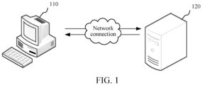
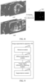
- FIG. 1 is a diagram of an application scenario of a method for image segmentation according to an embodiment.
- the application scenario includes a terminal 110 and a server 120 that are connected through a network.
- the terminal 110 may be a smart TV, a desktop computer or a mobile terminal, and the mobile terminal may include at least one of a mobile phone, a tablet computer, a notebook computer, a personal digital assistant, and a wearable device.
- the server 120 may be implemented by an independent server or a server cluster that includes a plurality of physical servers.
- the server 120 may sequentially select a current image frame according to a time sequence in a video; determine a reference image frame from image frames before the current image frame in the time sequence in the video; obtain first location information of a target object key point in the reference image frame; perform an affine transformation on the current image frame with reference to an affine transformation relationship between the first location information and a target object key point template, to obtain a target object diagram of the current image frame; perform a key point detection on the target object diagram, to obtain second location information of the target object key point; segment a target object from the target object diagram, to obtain segmentation information of the target object; and obtain the target object through segmentation from the current image frame according to the segmentation information and the second location information. Additionally, the server 120 may feed back a segmentation result to the terminal 110 for display.
- the terminal 110 may not send the video to the server for detection and analysis, and the terminal 110 itself may alternatively have a function of performing the image segmentation method in the embodiments of the present disclosure.
- the terminal itself has a computer processing function, and therefore may perform steps of the image segmentation method in the embodiments of the present disclosure on a video.
- the terminal 110 may further include a medical treatment detection terminal.
- the medical treatment detection terminal is an instrument terminal used for medical treatment detection.
- the medical treatment detection terminal may include a detection probe and a display device.
- the detection probe can play a role of a lens of a video camera. As the detection probe rotates, structures of a detected object can be clearly displayed on the display device.
- the medical treatment detection terminal may be a cardiac ultrasound detection instrument.
- the cardiac ultrasound detection instrument is an instrument for detecting a heart by using an ultrasound wave method. It may be understood that, the medical treatment detection terminal may alternatively be an instrument for performing ultrasound detection on another part of a human body.
- the terminal 110 is a cardiac ultrasound detection instrument
- a use scenario is described exemplarily.
- a doctor may place the detection probe in the terminal 110 at a heart part of a patient, to perform detection, and the detection probe may capture frames of cardiac ultrasound section diagrams by using the ultrasound wave, to form a cardiac ultrasound detection video to be displayed on the display device.
- the terminal 110 may alternatively transmit a cardiac ultrasound detection video to the server 120, to cause the server 120 to obtain a left ventricle in each frame of image of the video through segmentation.
- the foregoing example is only used for schematic description, and the terminal 110 does not need to be limited to the medical treatment detection terminal.
- the video may be not limited to the cardiac ultrasound detection video, and may alternatively be any other type of video, and what is to be detected may alternatively be not the left ventricle image, and may alternatively be any single target object in a video.
- the single target object may be a heart or a left ventricle of a heart.
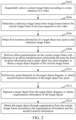
- FIG. 2 is a schematic flowchart of a method for image segmentation according to an embodiment.
- the computer device may be the server 120 or the terminal 110 in FIG. 1 .
- the method specifically includes the following steps:
- the video may be any type of video.
- the video may include image frames arranged in the time sequence.
- the video may include an ordinary video in daily life, for example, a video recorded in a mobile phone, or a video in various video programs of a video website.
- the video may alternatively include a particular type of video captured by using a particular detection technology, for example, an ultrasound video.
- the ultrasound video is a video captured when ultrasound detection is performed by using the ultrasound wave technology.
- the ultrasound video may be a video obtained by performing ultrasound detection on a human organ.
- the ultrasound video may include an abdomen ultrasound detection video, and the abdomen ultrasound detection video is a video captured when ultrasound detection is performed on an abdomen, for example, a video obtained by performing ultrasound detection on a part such as a liver, a gall bladder, or a stomach.
- the ultrasound video may be not limited to being obtained by detecting a human organ, and may be alternatively obtained, for example, by performing ultrasound detection on a non-human organ.
- the ultrasound video may include a cardiac ultrasound detection video.
- the cardiac ultrasound detection video is a video captured when ultrasound detection is performed on a heart.
- an image frame in a video may be a normal image frame.
- the normal image frame is an image frame of a target object presented in a normal state thereof.
- an image frame in a video may alternatively be an abnormal image frame.
- the abnormal image frame is an image frame of a target object presented in an abnormal state thereof.
- an image frame in a video may be a section diagram.
- the section diagram is an effect diagram of simulating that an object is "sectioned", and in the section diagram, the target object is presented in a "sectioned" state.
- an image frame may alternatively be an ultrasound section diagram.
- the ultrasound section diagram is a two-dimensional ultrasound diagram. After penetrating a chest wall, an ultrasound beam generated by the detection probe performs sector-shaped scanning, and echo signals reflected from a human body form a section image in the form of light spots. It may be understood that, expressed from a relatively vivid perspective, the reflected echo signals cause this scanning surface formed by the sector-shaped scanning to have an effect of "sectioning" an organ, and therefore the echo signals reflected from the human body form the section image in the form of light spots.
- the ultrasound section diagram may include a cardiac ultrasound section diagram
- the cardiac ultrasound detection video includes frames of cardiac ultrasound section diagrams arranged in a time sequence. That is, when the video is a cardiac ultrasound detection video, the current image frame may be a cardiac ultrasound section diagram.
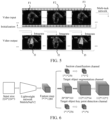
- FIG. 3 is a schematic diagram of describing a section diagram by using a cardiac ultrasound section diagram as an example.
- An ultrasound beam performs sector-shaped scanning, to obtain a scanning surface 302 having an effect of approximately "sectioning" a heart, and the cardiac ultrasound section diagram in FIG. 3 can be obtained. It may be understood that, the scanning surface does not really section the heart, and instead, according to distances relative to reflected echo signals, a section image obtained by approximately sectioning the scanning surface can be formed.
- all image frames in the video are sorted according to the time sequence. It may be understood that, image frames in the time sequence before the current image frame are all or some image frames in the video before the current image frame in the time sequence. For example, if the current image frame is the 5th image frame, image frames in the video before the 5th image frame in the time sequence may be all or some of first 4 image frames in the time sequence.
- the reference image frame is an image frame before the current image frame in the time sequence used to provide reference information when the target object in the current image frame is segmented. It may be understood that, target object segmentation may be performed on the current image frame by using time sequence priori reference information provided by the reference image frame.
- a quantity of reference image frames may be at least one, and at least one is one or more.
- the target object is an object needing to be obtained from the current image frame through segmentation.
- the target object may be any object intended to be obtained through segmentation.
- a target object in a bicycle match video, may be a bicycle in a video picture, and may alternatively be a participating athlete in a video picture.
- the target object key point is a point used for representing a feature of the target object.
- the target object key point is a left ventricle key point.
- the left ventricle key point refers to a point in a picture used for representing a feature of the left ventricle.
- left ventricle key points include a left ventricle top cusp and two endpoints of a mitral valve.
- the left ventricle top cusp namely, cardiac apex
- the mitral valve namely, the left atrioventricular valve
- the mitral valve is appended to the left fibrous atrioventricular ring, and formed by folds of the endocardium.
- the mitral valve has two valves, and the two endpoints of the mitral valve are endpoints of the two valves.
- the left ventricle key points are not limited to the foregoing three points, and points at other locations in the left ventricle may alternatively be set as key points.
- the first location information of the target object key point in the reference image frame is known.
- a current image frame is selected in a time sequence, and after segmentation on a target object in a current image frame is completed, a next image frame is selected as a new current image frame, to perform iteration in this way. Therefore, when the target object in the current image frame is segmented, an image frame in the time sequence before the current image frame has been segmented to obtain first location information of the target object key point in the image frame and segmentation information of the target object.
- the reference image frame determined in the image frames before the current image frame includes the first location information of the target object key point in the reference image frame and the segmentation information of the target object. Therefore, the computer device may obtain the known first location information of the target object key point in the reference image frame.
- a key point template is used to represent location information of a preset key point.
- the target object key point template is used to represent preset location information of the preset target object key point by using an image whose main region is the target object region as a reference. That is to say, preset location information of each target object key point in the target object key point template is location information of the target object key point represented on an image whose main region is the target object region. It may be understood that, the main region being the target object region means that the region area of the target object accounts for a main part in the image.
- an affine transformation operation such as rotation, translation, or tailoring may be performed on the current image frame, to obtain the target object diagram of the current image frame.
- the affine transformation relationship may be represented through an affine transformation matrix.
- the affine transformation relationship between the first location information and the target object key point template is used to represent affine transformation required when the first location information of the target object key point in the reference image frame is transformed to be consistent with the preset location information of the target object key point in the target object key point template.
- the performing an affine transformation on the current image frame according to the affine transformation relationship is equivalent to adjusting location information of the target object key point in the current image frame to preset location information of the target object key point in the target object key point template.
- the target object key point template is used to represent preset location information of the preset target object key point by using an image whose main region is the target object region as a reference. Therefore, after affine transformation is performed on the current image frame according to the foregoing affine transformation relationship, a region of interest (ROI), that is, the target object diagram of the target object in the current image frame can be obtained.
- ROI region of interest
- the region of interest is a region selected from an image and representing a focus to which image analysis pays attention. It may be understood that, the target object region in the target object diagram is the focal region.
- the computer device may extract the preset location information of the target object key point from the target object key point template, and calculate a transformation matrix according to the first location information and the preset location information of the target object key point in the target object key point template.
- the computer device may perform an affine transformation on the current image frame according to the transformation matrix, to obtain the target object diagram of the current image frame.
- the computer device may multiply the current image frame by the transformation matrix, to obtain the target object diagram of the current image frame.
- the computer device may directly perform image analysis on the target object diagram itself, and identify the target object key point from the target object diagram, to obtain the second location information of the target object key point.
- the computer device may input the target object diagram to a multi-task network, perform key point detection on the target object diagram through a key point detection model in the multi-task network, and output the second location information of the target object key point corresponding to the target object diagram.
- the multi-task network is a network that can perform a plurality of processing tasks in parallel.
- the multi-task network includes the key point detection model.
- the computer device may detect, through the key point detection model, a location information difference between the target object key point in the target object diagram and the target object key point in the target object key point template; and add preset location information of the target object key point in the target object key point template and the location information difference, to obtain the second location information of the target object key point in the target object diagram.
- the segmentation information of the target object is used to obtain the target object region from the target object diagram through segmentation, that is, used to distinguish the target object region from another region in the target object diagram.
- the segmentation information of the target object includes pixel points of the target object.
- the computer device may perform the target object segmentation on the target object diagram, to obtain a segmentation outline of the target object.
- the multi-task network may further include a segmentation model.
- the computer device may input the target object diagram to the pre-trained segmentation model in the multi-task network, perform semantic segmentation on the target object diagram through the segmentation model, and output the segmentation information of the corresponding target object.
- the computer device may predict, through the segmentation model, categories of all pixel points in the target object diagram, and form, according to pixel points belonging to the foreground category, the segmentation information of the target object corresponding to the target object diagram.
- the categories of all the pixel points include the foreground category and the background category.
- Pixel points belonging to the foreground category are pixel points of the target object, and can form the segmentation information of the target object corresponding to the target object diagram.
- the computer device may map the segmentation information of the target object in the target object diagram and the second location information of the target object key point to the current image frame.
- the computer device may perform, according to an inverse transformation operation of the affine transformation operation performed on the current image frame in step S208, an affine transformation on the segmentation information of the target object in the target object diagram and the second location information of the target object key point, to map the segmentation information of the target object in the target object diagram and the second location information of the target object key point to the current image frame.
- the target object in the current image frame to which the segmentation information of the target object and the second location information of the target object key point are mapped, the target object can be evidently distinguished and displayed, that is, the target object is obtained from the current image frame through segmentation.
- steps S202 to S214 may be performed.
- the computer device may perform the target object key point detection on the whole initial image frame, to obtain the location information of the target object key point in the initial image frame, segment the target object from the whole initial image frame, to obtain the segmentation information of the target object, and map the location information of the target object key point in the initial image frame and the segmentation information of the target object to the initial image frame.
- the computer device may alternatively input the whole initial image frame to the multi-task network, perform the target object key point detection on the initial image frame through the key point detection model in the multi-task network, perform semantic segmentation on the initial image frame through the segmentation model in the multi-task network, and output the segmentation information of the corresponding target object.
- FIG. 4 is described by using an example in which a video is a cardiac ultrasound detection video, an image frame in the video is a cardiac ultrasound section diagram, and a target object is a left ventricle.
- FIG. 4 is described by using an example in which a preceding image frame of a current image frame serves as a reference image frame, but the reference image frame is not merely limited to the preceding image frame of the current image frame.
- three points P1 to P3 are left ventricle key points of the preceding image frame, i.e., last frame landmark, and 402 is the current image frame.
- the computer device may perform an affine transformation on the current image frame according to an affine transformation relationship between first location information of the left ventricle key points (that is, the three points P1 to P3) in the preceding image frame and preset location information of the left ventricle key points in the left ventricle key point template, to obtain a left ventricle diagram (that is, an ROI image in FIG. 4 ).
- the computer device may input the ROI image separately to a key point detection model and a segmentation model in a multi-task network, and output segmentation information of a left ventricle in the ROI image, and a white region in 404 is the segmentation information of the left ventricle in the ROI image.
- the computer device further outputs second location information of the left ventricle key points in the ROI image, and locations of the three points in 406 represent the second location information of the left ventricle key points in the ROI image.
- An image 408 may be obtained by mapping the outputted information to the ROI image. Points 408a, 408b, and 408c in 408 are the left ventricle key points in the ROI image.
- a region 408d in 408 is a left ventricle region obtained through segmentation and represented by the segmentation information.
- the computer device may map the segmentation information of the left ventricle in the ROI image in 408 and the second location information of the left ventricle key point to the current image frame, to obtain a final result of the current image frame.
- the final result of the current image frame is the current image frame to which mapping is made and from which information related to the left ventricle is detected. It may be seen from the final result of the current image frame in FIG. 4 that, the left ventricle has been distinguished from the current image frame.
- an affine transformation network i.e., a temporal affine network, referred to as TAN, in FIG. 4 is used to represent a network framework involved in a process from affine transformation to detection of the information related to the left ventricle in the left ventricle diagram.
- the target object diagram can be determined relatively quickly without a large quantity of calculation, thereby saving computing resources.
- the obtained target object diagram is a region of interest of a target object, and is equivalent to removing much other unrelated image content, and then key point detection is performed on only the target object diagram, to obtain second location information of the target object key point; and the target object is segmented from the target object diagram, to obtain segmentation information of the target object, and the segmentation information and the second location information are mapped to the current image frame.
- the target object can be evidently distinguished from the current image frame to which the segmentation information and the second location information are mapped, to implement detection and identification on the target object in the current image frame, and segmentation and key point detection performed based on the target object diagram not only eliminate interference from other unrelated images, but also can reduce a calculation amount.
- the section diagram when the current image frame is a section diagram, the section diagram has a corresponding section category.
- Section categories may be classified according to formation types of images in section diagrams.
- the computer device may further perform section category identification on the target object diagram, to obtain a section category of the target object diagram.
- section categories when the current image frame is a cardiac ultrasound section diagram, section categories include at least one of an apical two-chamber view (A2C) and an apical four-chamber view (A4C). In another embodiment, the section categories may further include another category, such as, an apical five-chamber view.
- A2C apical two-chamber view
- A4C apical four-chamber view
- the section categories may further include another category, such as, an apical five-chamber view.
- the method before step S202, further includes: detecting initial location information of the target object key point from an initial image frame of the video; using the initial image frame as a preceding image frame and the initial location information as preceding location information, and detecting location information of a target object key point in a following image frame of the preceding image frame with reference to the preceding location information; using the following image frame as a preceding image frame and the location information of the target object key point in the following image frame as preceding location information, and returning to the operation of detecting location information of a target object key point in a following image frame of the preceding image frame with reference to the preceding location information, to perform iteration, until location information of a target object key point in a last image frame of the video is obtained; and using the last image frame as a preceding image frame of the initial image frame, and determining final location information of the target object key point in the initial image frame with reference to the location information of the target object key point in the last image frame.
- the computer device may detect the initial location information of the target object key point from the initial image frame. That is, rough key point detection is first performed on the initial image frame, to obtain the initial location information of the target object key point in the initial image frame.
- the computer device may detect location information of the target object key point in the second image frame (that is, a following image frame of the initial image frame) in the video with reference to the initial location information of the initial image frame, and then detect location information of the target object key point in the third image frame in the video with reference to the location information of the target object key point in the second image frame, and the rest can be deduced by analogy, to perform iteration, until location information of the target object key point in the last image frame in the video is obtained.
- the computer device may take the last image frame as a preceding image frame of the initial image frame, and determine final location information of the target object key point in the initial image frame with reference to the location information of the target object key point in the last image frame.
- the detecting location information of a target object key point in a following image frame of the preceding image frame with reference to the preceding location information includes: performing an affine transformation on the following image frame of the preceding image frame according to an affine transformation relationship between the preceding location information and the target object key point template, to obtain a target object diagram in the following image frame; and performing key point detection on the target object diagram in the following image frame, to obtain the location information of the target object key point in the following image frame.
- affine transformation is performed on the third image frame according to an affine transformation relationship between the location information of the target object key point in the second image frame and the target object key point template, to obtain the target object diagram in the third image frame
- key point detection is performed on the target object diagram in the third image frame, to obtain location information of the target object key point in the target object diagram in the third image frame
- the location information of the target object key point in the target object diagram in the third image frame may be mapped to the third image frame, to obtain location information of the target object key point in the third image frame.
- the rest can be deduced by analogy, until affine transformation is performed on the last image frame according to an affine transformation relationship between the location information of the target object key point in the penultimate image frame and the target object key point template, to obtain the target object diagram in the last image frame, and key point detection is performed on the target object diagram in the last image frame, to obtain location information of the target object key point in the last image frame.
- the computer device may take the last image frame as the preceding image frame of the initial image frame, perform an affine transformation on the initial image frame according to an affine transformation relationship between the location information of the target object key point in the last image frame and the target object key point template, to obtain the target object diagram in the initial image frame, and perform key point detection on the target object diagram in the initial image frame, to obtain final location information of the target object key point in the optimized initial image frame.
- the computer device may directly obtain the final location information of the target object key point in the optimized initial image frame.
- the computer device may further perform the target object segmentation on the foregoing obtained target object diagram in the initial image frame, to obtain the segmentation information of the target object in the target object diagram in the initial image frame.
- the computer device may obtain the target object from the initial image frame through segmenting according to the segmentation information of the target object in the target object diagram in the initial image frame and the location information of the target object key point.
- the computer device may map the segmentation information of the target object in the target object diagram in the initial image frame and the location information of the target object key point to the initial image frame, to obtain the target object from the initial image frame through segmenting.
- the computer device may further perform section classification on the target object diagram in the initial image frame, to obtain a section category of the initial image frame.
- the final location information of the target object key point in the initial image frame obtained according to the foregoing manner is optimized and more accurate. Therefore, when the reference image frames include the initial image frame, affine transformation is performed on the current image frame with reference to an affine transformation relationship between the final location information of the target object key point in the initial image frame and the target object key point template, to enable the obtained target object diagram of the current image frame to be more accurate.
- the segmentation information of the target object in the target object diagram and the second location information of the target object key point that are subsequently obtained are more accurate, and therefore mapping of more accurate segmentation information and location information of the target object key point to the current image frame enables information related to the target object image and detected in the current image frame to be more accurate.
- step S204 includes: determining, in an ascending order of distances from the current image frame, a preset quantity of image frames in the video before the current image frame as one or more reference image frames.
- Step S214 includes: calculating, when there are a plurality of reference image frames, an average of segmentation information of the target object determined according to first location information of the target object key point in each reference image frame, to obtain final segmentation information of the target object; calculating an average value of second location information determined according to the first location information of the target object key point in each reference image frame, to obtain final second location information of the target object key point; and mapping the final segmentation information of the target object and the final second location information of the target object key point to the current image frame.
- the preset quantity may be one or more.
- a plurality of described in the embodiments of the present disclosure refers to at least two.
- the computer device may perform steps S206 to S210 for each reference image frame. That is, the computer device may perform an affine transformation on the current image frame with reference to an affine transformation relationship between first location information of the target object key point in each reference image frame and the target object key point template, to obtain a target object diagram of the current image frame.
- the quantity of reference image frames corresponds to the quantity of times of affine transformation performed on the current image frame, and a corresponding quantity of target object diagrams of the current image frame are obtained.
- key point detection is performed on each target object diagram, to obtain second location information of the target object key point, and a target object is obtained from the target object diagram through segmentation, to obtain segmentation information of the target object.
- a target object is obtained from the target object diagram through segmentation, to obtain segmentation information of the target object.
- the computer device may calculate, when there are a plurality of reference image frames, an average of segmentation information of the target object determined according to first location information of the target object key point in each reference image frame, to obtain final segmentation information of the target object; and calculate an average value of second location information determined according to the first location information of the target object key point in each reference image frame, to obtain final second location information of the target object key point.
- the computer device may map the final segmentation information of the target object and the final second location information of the target object key point to the current image frame.
- FIG. 5 is a schematic principle diagram of multi-time-sequence processing according to an embodiment, that is, a schematic principle diagram of segmenting a target object in a current image frame by using first location information of a target object key point in a plurality of image frames in front in a time sequence.
- FIG. 5 is described by using an example in which a video is a cardiac ultrasound detection video, an image frame in the video is a cardiac ultrasound section diagram, and a target object is a left ventricle.
- a complete video is inputted.
- An initial image frame F1 has no location information of a left ventricle key point in an earlier frame.
- left ventricle key point detection may be performed on the initial image frame F1 by using a multi-task network, location information of a detected left ventricle key point is used as time sequence affine transformation information of a next frame, and affine transformation is performed on a following image frame F2 with reference to an affine transformation relationship between the location information of the left ventricle key point and a left ventricle key point template, to obtain a corresponding left ventricle diagram; then key point detection is performed on the left ventricle diagram thereof, the location information of the detected left ventricle key point is mapped to the following image frame F2, then location information of the left ventricle key point in F2 after mapping is used as time sequence affine transformation information of a second following image frame F3, and affine transformation and subsequent processing are performed on the image frame F3, to obtain corresponding location information of the left ventricle key point; and the rest can be deduced by analogy, until key point information of the last image frame in the video is obtained.
- the location information of the left ventricle key point in the last image frame is returned to serve as affine transformation reference information of the initial image frame of the video, affine transformation is performed on the initial image frame, to obtain the corresponding left ventricle diagram, and then based on the left ventricle diagram of the initial image frame, optimized and relatively reliable final location information of the left ventricle key point in the initial image frame is calculated. Based on the optimized final location information of the left ventricle key point in the initial image frame, the current image frame is sequentially selected according to a time sequence.
- the final location information of the left ventricle key point in the initial image frame may be directly obtained, segmentation information of the left ventricle in the initial image frame is determined according to the foregoing left ventricle diagram of the initial image frame, and the final location information of the left ventricle key point in the initial image frame and the segmentation information of the left ventricle are mapped to the initial image frame.
- the current image frame is the second image frame, there is only the initial image frame before the second image frame.
- the method further includes: inputting the target object diagram to a multi-task network, and performing encoding on the target object diagram to obtain a feature map of the target object diagram.
- Step S210 includes: performing the key point detection on the feature map through a key point detection model in the multi-task network, and outputting the second location information of the target object key point corresponding to the target object diagram.
- Step S212 includes: performing a semantic segmentation on the feature map through a segmentation model in the multi-task network, and outputting the segmentation information of the corresponding target object.
- the feature map is a feature map obtained after an image and a filter are convoluted. It may be understood that, compared with the original image, the feature map has features extracted, and can better highlight image features.
- the multi-task network may further include a lightweight encoding model.
- the computer device may input the target object diagram to the encoding model in the multi-task network, and perform encoding to obtain a feature map of the target object diagram.
- the lightweight encoding model may include MobileNetV2.
- the computer device may perform, through the key point detection model and by using the L1-norm loss function, regression to obtain the second location information of the target object key point corresponding to the target object diagram.
- FIG. 6 is a schematic structural diagram of a multi-task network according to an embodiment.
- an inputted 224*224*3 image is a target object diagram (ROI image), and encoded through a lightweight network MobileNetV2, to output a 7*7*1280 feature map.
- the feature map is separately inputted to 3 different task channels, that is, separately inputted to a section classification channel, a target object segmentation channel, and a target object key point detection channel, and subject to three different types of detection in parallel.
- a section classification model in the section classification channel processes the feature map, to finally obtain a binary classification result of section categories.
- a key point detection model in the target object key point detection channel performs regression processing, to output X coordinate information and Y coordinate information of 3 target object key points, and therefore location information of the target object key points is 6 location parameters.
- Secondary decoding is performed through the segmentation model in the target object segmentation channel, to obtain categories of all pixel points in a decoded image, and the categories of the pixel points include a foreground category and a background category. It may be understood that, pixel points belonging to the foreground category are the foreground, and pixel points belonging to the background category are the background.
- the size of the outputted decoded image is 112*112 that is 1/2 of the size of the inputted target object diagram.
- the decoded image may continue to be interpolated, to cause the size thereof and the size of the inputted target object diagram to be consistent and be 224*224, and then segmentation information of a target object corresponding to the target object diagram is formed according to the pixel points in the interpolated decoded image that belong to the foreground category.
- the target object diagram is encoded through the multi-task network, to obtain the feature map.
- the feature map can more accurately express feature information of the target object diagram.
- the feature map is processed through the key point detection model and the segmentation model in the multi-task network simultaneously, thereby improving efficiency of detecting the information of the target object image, and achieving relatively high real-time performance.
- the multi-task network is equivalent to use of a small network to achieve accuracy of a large network, and is lightweight.
- the method further includes: performing section classification on the feature map through a section classification model in the multi-task network, to obtain a section category of the current image frame.
- the multi-task network further includes a section classification model.
- the section classification model is a model used for detecting a section category of an image.
- the section classification model outputs a section category of the target object diagram. Because the target object diagram is extracted from the current image frame, the section category of the target object diagram is the section category of the current image frame.
- the computer device may use a cross entropy loss algorithm through the section classification model, to obtain the section category of the current image frame.
- the method further includes: determining, after a section category of each image frame in the video is determined, a quantity of image frames corresponding to each section category; and using a section category corresponding to a largest quantity of image frames as a section category corresponding to the video.
- voting is equivalent to voting the determined section categories; and a section category corresponding to a largest quantity of votes is taken as a section category corresponding to the video.
- the voting herein is not human voting, but a computer processing procedure.
- f1 and f2 are displayed as A2C, while f3 is displayed as A4C. Therefore, it is detected that section categories of different image frames in the same video are different, while usually, the same video belongs to a section category. Therefore, the determined section categories may be voted. In FIG. 5 , this category A2C has a largest quantity of votes, and therefore, it may be determined that the section category of the video is A2C instead of A4C.
- the section category of the video can be further identified, which is equivalent to that segmentation of the target object in the video and identification of the standard section can be completed at the same time, thereby providing a larger information amount for subsequent processing more quickly.
- a section category corresponding to a largest quantity of votes is taken as a section category corresponding to the video. Accuracy of the determined section category can be ensured, and then more accurate reference information can be provided for subsequent processing.
- the performing key point detection on the feature map through a key point detection model in the multi-task network includes: inputting the feature map to the pre-trained key point detection model, and outputting a location information difference between the target object key point in the target object diagram and the target object key point in the target object key point template; and adding preset location information of the target object key point in the target object key point template and the location information difference, to obtain the second location information of the target object key point in the target object diagram.
- the computer device may extract a target object diagram in an sample image frame in advance, and perform machine learning training according to the target object diagram in the sample image frame and with reference to a labeled sample location difference between a target object key point in the target object diagram and a target object key point in a target object key point template, to obtain a key point detection model. Therefore, after a feature map is inputted to the key point detection model, a location information difference between the target object key point in the target object diagram and the target object key point in the target object key point template may be outputted.
- a location information difference between the target object key point in the target object diagram and the target object key point in the target object key point template is outputted through the key point detection model; and preset location information of the target object key point in the target object key point template and the location information difference are added, to obtain the second location information of the target object key point in the target object diagram.
- the location information difference has a smaller data amount than that of complete location information, thereby saving computing resources.
- the performing the semantic segmentation on the feature map through the segmentation model in the multi-task network, and outputting the segmentation information of the corresponding target object includes: inputting the feature map to a pre-trained segmentation model and performing decoding on the feature map, and outputting a first classification probability and a second classification probability of each pixel point in an obtained decoded image belonging to a foreground category and a background category; selecting, for each pixel point in the decoded image, a category corresponding to a larger classification probability of the first classification probability and the second classification probability corresponding to the pixel point as a category of the pixel point; and determining, according to pixel points in the decoded image that belong to the foreground category, the segmentation information of the target object corresponding to the target object diagram.
- the segmentation model may predict a classification probability that each pixel point in the decoded image belongs to the foreground category or the background category.
- the segmentation information of the target object corresponding to the target object diagram may be obtained directly according to pixel points in the decoded image that belong to the foreground category.
- the size of the decoded image may be inconsistent with the size of the target object diagram.
- the decoded image may be interpolated, to cause the size thereof and the size of the inputted target object diagram to be consistent, and then segmentation information of a target object corresponding to the target object diagram is formed according to the pixel points in the interpolated decoded image that belong to the foreground category.
- a category of each pixel point is determined through the segmentation model, and then segmentation is implemented, thereby refining the segmentation granularity, and improving segmentation accuracy.
- operations of training the segmentation model include: obtaining sample image frames in an sample video; obtaining first target object segmentation labels respectively corresponding to the sample image frames; and inputting the sample image frames and the corresponding first target object segmentation labels to an initial segmentation model, and performing iterative machine learning training, to obtain a basic segmentation model.
- the sample video is a video used as training data to train the machine learning model.
- the sample image frame is an image frame in the training video used for training the machine learning model. There may be a plurality of sample videos.
- the training data may include the sample video, and a first target object segmentation label corresponding to each sample image frame in the sample video.
- the first target object segmentation label is used to label a target object outline in the corresponding sample image frame.
- the first target object segmentation label may be a manually added label.
- the first target object segmentation label may perform labeling in a mask image of the sample image frame.
- Inputting the first target object segmentation label to the initial segmentation model is equivalent to inputting the mask image of the sample image frame to the initial segmentation model.
- Labeling the mask image of the sample image frame with the first target object segmentation label is equivalent to labeling the target object outline in the sample image frame.
- the computer device may input the sample image frames and the corresponding first target object segmentation labels to a preset initial segmentation model, and perform iterative machine learning training, to obtain a basic segmentation model.
- the computer device may input the target object diagram or the feature map of the target object diagram to the basic segmentation model, and perform target object segmentation, to obtain segmentation information of the target object diagram.
- the computer device may alternatively further optimize and adjust the segmentation model, to improve accuracy of the segmentation model, and perform the target object segmentation on the target object diagram or the feature map of the target object diagram based on the optimized segmentation model.
- the segmentation loss is used to represent a difference between a predicted value and an actual value. A larger difference between the two indicates a larger segmentation loss, and a smaller difference between the two indicates a smaller segmentation loss.
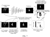
- FIG. 7 shows a method for adaptively training a segmentation model for segmenting a smooth edge according to an embodiment.
- FIG. 7 is described by using an example in which a video is a cardiac ultrasound detection video, an image frame in the video is a cardiac ultrasound section diagram, and a target object is a left ventricle. Therefore, the first target object segmentation label is the first left ventricle segmentation label, and the second target object segmentation label is the second left ventricle segmentation label. With reference to FIG. 7 , the first left ventricle segmentation label is manually labeled.
- a dark-colored histogram in 702 represents background pixel points
- a light-colored histogram represents left ventricle pixel points (that is, foreground pixel points)
- a left group of histograms in 702 represent quantities of background pixel points and left ventricle pixel points in the t th sample image frame when segmentation is performed by using the second left ventricle segmentation label. It can be learned that, the background pixel points are evidently more than the left ventricle pixel points, and therefore balance processing needs to be performed. Pixel points other than hard example pixel points and left ventricle pixel points are removed from the t th sample image frame, thereby reducing an unnecessary calculation amount brought by excessive background pixel points.
- the right group of histograms represent quantities of hard example pixel points and left ventricle pixel points in the t th sample image frame having pixel points removed. It is evidently seen from the right histogram that the quantities of background pixel points and left ventricle pixel points are relatively balanced, and cannot go so far as to have an excessively large difference.
- a mask image of the t th sample image frame having pixel points removed is 704. It can be learned that 704 still includes the second left ventricle segmentation label of the t th sample image frame. Then, each sample image frame having a pixel point removed and a corresponding second left ventricle segmentation label may be inputted to the basic segmentation model, that is, 2 is performed, and iterative model optimization and training are performed.
- FIG. 7 is used for only exemplification, but not used for limitation.
- the segmentation model in the model training process, by automatically performing, through a computer, optical flow tracking to generate a new target object segmentation label, that is, the second target object segmentation label, the segmentation model can be adaptively optimized in combination with hard example mining, and the optimization effect can be automatically achieved in the model training process, thereby reducing a large quantity of laborious test operations.
- the method for adaptively training a segmentation model for segmenting a smooth edge only points on a label outline formed by the target object segmentation label are selected to perform optical flow tracking, that is, optical flow tracking is locally performed, and therefore no huge calculation amount is required, thereby saving computing resources.
- operations of generating the target object key point template include: expanding a label outline formed by a first target object segmentation label of each sample image frame in a sample video to a preset range; enlarging each expanded range according to a location law of the target object in a cardiac ultrasound section diagram of a preset section category, to obtain a tailoring range; performing tailoring from each of the sample image frames to obtain a tailored picture matching the tailoring range; averaging location information of the target object key point in each tailored picture, to obtain preset location information of the target object key point; and generating the target object key point template according to the preset location information of the target object key point.
- each sample image frame in each sample video has a corresponding first target object segmentation label.
- the target object segmentation label is a label used for representing an external outline of the target object.
- the computer device may expand a label outline formed by the corresponding first target object segmentation label in each sample image frame to a preset range, and a region within a label outline formed after expansion to the preset range can basically cover target object regions in cardiac ultrasound section diagrams of all different section categories. Therefore, the region within the label outline formed after expansion to the preset range may be roughly used as the location of the target object.
- the location law of the left ventricle in the section diagrams of the preset different section categories is that the left ventricle is located at an upper left corner of the cardiac ultrasound section diagram.
- the computer device may enlarge the width and the height of the left ventricle by 50% respectively toward the left and the bottom of the sample image frame, to obtain a tailoring range. It may be understood that, besides covering the left ventricle region, the enlarged tailoring range can further include more information used for determining a section category.
- the computer device may average location information of the target object key points in all tailored pictures, to obtain preset location information of the target object key point; and generate the target object key point template according to the preset location information of the target object key point.
- the computer device may determine a target object key point represented by the first target object segmentation label in the tailored picture, and determine location information of the target object key point in the tailored picture.
- the computer device may average location information of the target object key points in all tailored pictures, to obtain preset location information of the target object key point.
- sample videos belonging to different section categories may be used as training data, and therefore sample image frames also correspond to a plurality of section categories.
- the target object key point template determined based on sample image frames of different section categories can be used for detecting image frames of a plurality of different section categories.
- FIG. 8 is a schematic principle diagram of generating a target object key point template according to an embodiment.
- FIG. 8 is described by using an example in which an image frame in the video is a cardiac ultrasound section diagram, and a target object is a left ventricle. Then, the left ventricle key point template is the target object key point template to be generated. With reference to FIG. 8
- cardiac ultrasound section diagrams of different section categories A2C and A4C are used as basic data for generating the left ventricle key point template, and the following series of processing is performed: expanding a label outline of a left ventricle in each cardiac ultrasound section diagram serving as a sample image frame to a specific range, enlarging the expanded range according to the location law of the left ventricle in different categories of section diagrams to obtain a tailoring range, then capturing an image according to the tailoring range and adjusting the image to a tailored picture having a size matching the input size of the multi-task network, and averaging location information of a left ventricle key point in all tailored pictures, to obtain preset location information of the left ventricle key point.
- the left ventricle key point template 802 is finally generated according to the preset location information of the left ventricle key point.
- the location information of the target object key point determined through the foregoing method is averaged, thereby improving accuracy and applicability of the target object key point template. Then, an accurate reference basis is provided for subsequent affine transformation.
- an apparatus for image segmentation 900 includes: a selection module 902, an affine transformation module 904, a target object information obtaining module 906, and a segmentation module 908.
- the selection module 902 is configured to sequentially select a current image frame according to a time sequence in a video.
- the affine transformation module 904 is configured to determine a reference image frame from image frames before the current image frame in the time sequence in the video; obtain first location information of a target object key point in the reference image frame; and perform an affine transformation on the current image frame with reference to an affine transformation relationship between the first location information and a target object key point template, to obtain a target object diagram of the current image frame.
- the target object information obtaining module 906 is configured to perform a key point detection on the target object diagram, to obtain second location information of the target object key point; and segment a target object from the target object diagram, to obtain segmentation information of the target object.
- the segmentation module 908 is configured to obtain the target object through segmentation from the current image frame according to the segmentation information and the second location information.
- the apparatus 900 further includes: an initial frame key point information optimization module 901, configured to detect initial location information of the target object key point from an initial image frame of the video; take the initial image frame as a preceding image frame and the initial location information as preceding location information, and detecting location information of a target object key point in a following image frame of the preceding image frame with reference to the preceding location information; take the following image frame as a preceding image frame and the location information of the target object key point in the following image frame as preceding location information, and return to the operation of detecting location information of a target object key point in a following image frame of the preceding image frame with reference to the preceding location information, to perform iteration, until location information of a target object key point in a last image frame of the video is obtained; and take the last image frame as a preceding image frame of the initial image frame, and determine final location information of the target object key point in the initial image frame with reference to the location information of the target object key point in the last
- the initial frame key point information optimization module 901 is further configured to perform an affine transformation on the following image frame of the preceding image frame according to an affine transformation relationship between the preceding location information and the target object key point template, to obtain a target object diagram in the following image frame; and perform key point detection on the target object diagram in the following image frame, to obtain the location information of the target object key point in the following image frame.
- the affine transformation module 904 is further configured to determine, in an ascending order of distances from the current image frame, a preset quantity of image frames in the video before the current image frame as one or more reference image frames; and the segmentation module 908 is further configured to calculate, when there are a plurality of reference image frames, an average of segmentation information of the target object determined according to first location information of the target object key point in each reference image frame, to obtain final segmentation information of the target object; calculate an average value of second location information determined according to the first location information of the target object key point in each reference image frame, to obtain final second location information of the target object key point; and map the final segmentation information of the target object and the final second location information of the target object key point to the current image frame.
- the target object information obtaining module 906 is further configured to input the target object diagram to a multi-task network, and perform encoding to obtain a feature map of the target object diagram; perform key point detection on the feature map through a key point detection model in the multi-task network, and output the second location information of the target object key point corresponding to the target object diagram; and perform semantic segmentation on the feature map through a segmentation model in the multi-task network, and output the segmentation information of the corresponding target object.
- the target object information obtaining module 906 is further configured to perform section classification on the feature map through a section classification model in the multi-task network, to obtain a section category of the current image frame; determine, after a section category of each image frame in the video is determined, a quantity of image frames corresponding to each section category; and take a section category corresponding to a largest quantity of image frames as a section category corresponding to the video.
- the target object information obtaining module 906 is further configured to input the feature map to the pre-trained key point detection model, and output a location information difference between the target object key point in the target object diagram and the target object key point in the target object key point template; and add preset location information of the target object key point in the target object key point template and the location information difference, to obtain the second location information of the target object key point in the target object diagram.
- the target object information obtaining module 906 is further configured to input the feature map to a pre-trained segmentation model and perform decoding on the feature map, and output a first classification probability and a second classification probability of each pixel point in an obtained decoded image belonging to a foreground category and a background category; select, for each pixel point in the decoded image, a category corresponding to a larger classification probability of the first classification probability and the second classification probability corresponding to the pixel point as a category of the pixel point; and determine, according to pixel points in the decoded image that belong to the foreground category, the segmentation information of the target object corresponding to the target object diagram.
- the target object information obtaining module 906 is further configured to obtain sample image frames in a sample video; obtain first target object segmentation labels respectively corresponding to the sample image frames; and input the sample image frames and the corresponding first target object segmentation labels to an initial segmentation model, and perform iterative machine learning training, to obtain a basic segmentation model.
- the target object information obtaining module 906 is further configured to sequentially select current sample image frames from the sample image frames; for each current sample image frame, select, from a label outline formed by a first target object segmentation label of a preceding sample image frame of the current sample image frame, a preset quantity of boundary feature points representing a target object boundary; track location information of the boundary feature points in the current sample image frame through an optical flow tracking operation; connect the location information of the boundary feature points in the current sample image frame and perform smoothing, to obtain a second target object segmentation label of the current sample image frame; and perform iterative optimization and training on the basic segmentation model according to each sample image frame and a corresponding second target object segmentation label, to obtain an optimized segmentation model.
- the target object information obtaining module 906 is further configured to mine a hard example pixel point in the current sample image frame through the basic segmentation model, where the hard example pixel point is a background pixel point that is classified incorrectly; remove a pixel point other than the hard example pixel point and a target object pixel point from the current sample image frame; and input each sample image frame having a pixel point removed and a corresponding second target object segmentation label to the basic segmentation model, and perform iterative model optimization and training.
- the affine transformation module 904 is further configured to expand a label outline formed by a first target object segmentation label of each sample image frame in a sample video to a preset range; enlarge each expanded range according to a location law of the target object in the image frames, to obtain a tailoring range; perform tailoring from each of the sample image frames to obtain a tailored picture matching the tailoring range; average location information of the target object key point in each tailored picture, to obtain preset location information of the target object key point; and generate the target object key point template according to the preset location information of the target object key point.
- FIG. 11 is a schematic diagram of an inner structure of a computer device according to an embodiment.
- the computer device may be the server 120 shown in FIG. 1 . It may be understood that, the computer device may alternatively be the terminal 110.
- the computer device includes a processor, a memory, and a network interface connected through a system bus.
- the memory includes a non-volatile storage medium and an internal memory.
- the non-volatile storage medium of the computer device may store an operating system and a computer program.
- the processor When the computer program is executed, the processor may be caused to perform an image segmentation method.
- the processor of the computer device is configured to provide calculation and control capabilities, to support running of the entire computer device.
- the internal memory may store a computer program, the computer program, when executed by the processor, causing the processor to perform an image segmentation method.
- the network interface of the computer device is configured to perform network communication.
- FIG. 11 is only a block diagram of a part of a structure related to a solution of the present disclosure and does not limit the computer device to which the solution of the present disclosure is applied.
- the computer device may include more or fewer members than those in the drawings, or include a combination of some members, or include different member layouts.
- the image segmentation apparatus provided in the present disclosure may be implemented in a form of a computer program.
- the computer program may be run on the computer device shown in FIG. 11 , and the non-volatile storage medium of the computer device may store program modules constituting the image segmentation apparatus, for example, the selection module 902, the affine transformation module 904, the target object information obtaining module 906 and the segmentation module 908 shown in FIG. 9 .
- the computer program constituted by the program modules is used for causing the computer device to perform the steps in the image segmentation method in the embodiments of the present disclosure described in this specification.
- the computer device may perform, through the target object information obtaining module 906, key point detection on the target object diagram, to obtain second location information of the target object key point; and segment a target object from the target object diagram, to obtain segmentation information of the target object.
- the computer device may obtain, through the segmentation module 908, the target object through segmentation from the current image frame according to the segmentation information and the second location information.
- a person of ordinary skill in the art may understand that all or some of the processes of the methods in the foregoing embodiments may be implemented by a computer program instructing relevant hardware.
- the program may be stored in a non-volatile computer-readable storage medium. When the program is executed, the processes of the foregoing method embodiments are performed.
- Any reference to a memory, a storage, a database, or another medium used in the various embodiments provided in the present disclosure may include a non-volatile and/or volatile memory.
- the non-volatile memory may include a read-only memory (ROM), a programmable ROM (PROM), an electrically programmable ROM (EPROM), an electrically erasable programmable ROM (EEPROM) or a flash memory.
Landscapes
- Engineering & Computer Science (AREA)
- Theoretical Computer Science (AREA)
- Physics & Mathematics (AREA)
- General Physics & Mathematics (AREA)
- Computer Vision & Pattern Recognition (AREA)
- Multimedia (AREA)
- Data Mining & Analysis (AREA)
- Bioinformatics & Cheminformatics (AREA)
- Artificial Intelligence (AREA)
- Bioinformatics & Computational Biology (AREA)
- Evolutionary Biology (AREA)
- Evolutionary Computation (AREA)
- General Engineering & Computer Science (AREA)
- Life Sciences & Earth Sciences (AREA)
- Computational Linguistics (AREA)
- Software Systems (AREA)
- Image Analysis (AREA)
Claims (14)
- Computerumgesetztes Verfahren zur Bildsegmentierung, das von einer Computervorrichtung umgesetzt wird, umfassend:sequenzielles Auswählen (S202) eines aktuellen zweidimensionalen, 2D, Einzelbildes gemäß einer Zeitsequenz in einem Video;Bestimmen (S204) eines 2D-Referenzeinzelbildes aus 2D-Einzelbildern vor dem aktuellen 2D-Einzelbild in der Zeitsequenz in dem Video;Erzielen (S206) von ersten 2D-Standortinformationen eines angestrebten Objektkernpunktes in dem 2D-Referenzeinzelbild;Ausführen (S208) einer affinen Transformation an dem aktuellen 2D-Einzelbild mit Bezug auf eine affine Transformationsbeziehung zwischen den ersten 2D-Standortinformationen und einer Mustervorlage eines angestrebten Objektkernpunktes, um ein 2D-Zielobjektdiagramm des aktuellen 2D-Einzelbildes zu erzielen, wobei das 2D-Zielobjektdiagramm ein Bild einer Interessenregion, ROI, eines Zielobjekts ist, aus dem unzusammenhängender Bildinhalt des aktuellen 2D-Einzelbildes entfernt wurde, um die Bearbeitung auf das Zielobjekt zu fokussieren, und wobei das Ausführen der affinen Transformation an dem aktuellen 2D-Einzelbild mit Bezug auf die affine Transformationsbeziehung das Anpassen der 2D-Standortinformationen des angestrebten Objektkernpunktes in dem aktuellen 2D-Einzelbild umfasst, um die 2D-Standortinformationen des angestrebten Objektkernpunktes in der Mustervorlage eines angestrebten Objektkernpunktes voreinzustellen;Ausführen (S210) einer 2D-Kernpunktdetektion an dem 2D-Zielobjektdiagramm, um zweite 2D-Standortinformationen (406) des angestrebten Objektkernpunktes zu erzielen;Segmentieren (S212) eines Zielobjekts aus dem 2D-Zielobjektdiagramm, um Segmentierungsinformationen (404) des Zielobjekts zu erzielen; undErzielen (S214) des Zielobjekts durch Segmentierung aus dem aktuellen 2D-Einzelbild gemäß den Segmentierungsinformationen und den zweiten 2D-Standortinformationen und basierend auf dem Ausführen einer Abbildung von dem 2D-Zielobjektdiagramm auf das aktuelle 2D-Einzelbild.
- Verfahren nach Anspruch 1, ferner umfassend:vor dem sequenziellen Auswählen (S202) des aktuellen 2D-Einzelbildes gemäß der Zeitsequenz in dem Video,Detektieren von anfänglichen 2D-Standortinformationen eines angestrebten Objektkernpunktes aus einem anfänglichen 2D-Einzelbild des Videos;Verwenden des anfänglichen 2D-Einzelbildes als ein vorhergehendes 2D-Einzelbild und der anfänglichen 2D-Standortinformationen als vorhergehende 2D-Standortinformationen, und Detektieren von 2D-Standortinformationen eines angestrebten Objektkernpunktes in einem folgenden 2D-Einzelbild des vorhergehenden 2D-Einzelbildes mit Bezug auf die vorhergehenden 2D-Standortinformationen;Verwenden des folgenden 2D-Einzelbildes als ein vorhergehendes 2D-Einzelbild und der 2D-Standortinformationen des angestrebten Objektkernpunktes in dem folgenden 2D-Einzelbild als vorhergehende 2D-Standortinformationen, und Zurückkehren zu dem Vorgang des Detektierens von 2D-Standortinformationen eines angestrebten Objektkernpunktes in einem folgenden 2D-Einzelbild der vorhergehenden 2D-Einzelbildes mit Bezug auf die vorhergehenden 2D-Standortinformationen, um eine Iteration auszuführen, bis 2D-Standortinformationen eines angestrebten Objektkernpunktes in einem letzten 2D-Einzelbild des Videos erzielt werden; undVerwenden des letzten 2D-Einzelbildes als ein vorhergehende 2D-Einzelbild des anfänglichen 2D-Einzelbildes, und Bestimmen von endgültigen 2D-Standortinformationen des angestrebten Objektkernpunktes in dem anfänglichen 2D-Einzelbild mit Bezug auf die 2D-Standortinformationen des angestrebten Objektkernpunktes in dem letzten 2D-Einzelbild.
- Verfahren nach Anspruch 2, wobei das Detektieren der 2D-Standortinformationen des angestrebten Objektkernpunktes in dem folgenden 2D-Einzelbild des vorhergehenden 2D-Einzelbildes mit Bezug auf die vorhergehenden 2D-Standortinformationen umfasst:Ausführen einer affinen Transformation an dem folgenden 2D-Einzelbild des vorhergehenden 2D-Einzelbildes gemäß einer affine Transformationsbeziehung zwischen den vorhergehenden 2D-Standortinformationen und der Mustervorlage eines angestrebten Objektkernpunktes, um ein 2D-Zielobjektdiagramm in dem folgenden 2D-Einzelbild zu erzielen; undAusführen einer 2D-Kernpunktdetektion an dem 2D-Zielobjektdiagramm in dem folgenden 2D-Einzelbild, um die 2D-Standortinformationen des angestrebten Objektkernpunktes in dem folgenden 2D-Einzelbild zu erzielen.
- Verfahren nach einem der Ansprüche 1 bis 3, wobei das Bestimmen (S204) des 2D-Referenzeinzelbildes aus 2D-Einzelbildern vor dem aktuellen 2D-Einzelbild in der Zeitsequenz in dem Video umfasst:Bestimmen, in aufsteigender Reihenfolge von Abständen aus dem aktuellen 2D-Einzelbild, einer voreingestellten Menge von Einzelbildern in dem Video vor dem aktuellen 2D-Einzelbild als ein oder mehrere Referenz-2D-Einzelbilder; unddas Erzielen des Zielobjekts durch Segmentieren aus dem aktuellen 2D-Einzelbild gemäß den Segmentierungsinformationen und den zweiten 2D-Standortinformationen umfasst:Berechnen, wenn es eine Vielzahl von 2D-Referenzeinzelbildern gibt, eines Durchschnitts von Segmentierungsinformationen des Zielobjekts, die gemäß den ersten 2D-Standortinformationen des angestrebten Objektkernpunktes in jedem 2D-Referenzeinzelbild bestimmt werden, um endgültige Segmentierungsinformationen des Zielobjekts zu erzielen;Berechnen einen Mittelwertes von zweiten 2D-Standortinformationen, die gemäß den ersten 2D-Standortinformationen des angestrebten Objektkernpunktes in jedem 2D-Referenzeinzelbild bestimmt werden, um endgültige zweite 2D-Standortinformationen des angestrebten Objektkernpunktes zu erzielen; undAbbilden der endgültigen Segmentierungsinformationen des Zielobjekts und der endgültigen zweiten 2D-Standortinformationen des angestrebten Objektkernpunktes auf das aktuelle 2D-Einzelbild.
- Verfahren nach einem der Ansprüche 1 bis 3, ferner umfassend:Eingeben des 2D-Zielobjektdiagramms in ein Multitasking-Netzwerk und Ausführen des Codierens an dem 2D-Zielobjektdiagramm, um eine Merkmalskarte des 2D-Zielobjektdiagramms zu erzielen,wobei das Ausführen der Kernpunktdetektion an dem 2D-Zielobjektdiagramm zum Erzielen der zweiten 2D-Standortinformationen des angestrebten Objektkernpunktes umfasst:Ausführen der Kernpunktdetektion an der Merkmalskarte über ein Kernpunktdetektionsmodell in dem Multitasking-Netzwerk, und Ausgeben der zweiten 2D-Standortinformationen des angestrebten Objektkernpunktes, die dem 2D-Zielobjektdiagramm entsprechen; undwobei das Segmentieren des 2D-Zielobjekts aus dem 2D-Zielobjektdiagramm zum Erzielen der Segmentierungsinformationen des 2D-Zielobjekts umfasst:
Ausführen einer semantischen Segmentierung an der Merkmalskarte über ein Segmentierungsmodell in dem Multitasking-Netzwerk, und Ausgeben der Segmentierungsinformationen des entsprechenden Zielobjekts. - Verfahren nach Anspruch 5, ferner umfassend:nach dem Eingeben des 2D-Zielobjektdiagramms in das Multitasking-Netzwerk und Ausführen des Codierens an dem 2D-Zielobjektdiagramm, um die Merkmalskarte des 2D-Zielobjektdiagramms zu erzielen,Ausführen einer Abschnittsklassifizierung an der Merkmalskarte über ein Abschnittsklassifizierungsmodell in dem Multitasking-Netzwerk, um eine Abschnittskategorie des aktuellen 2D-Einzelbildes zu erzielen;Bestimmen, nachdem eine Abschnittskategorie jedes 2D-Einzelbildes in dem Video bestimmt wurde, einer Menge von 2D-Einzelbildern, die jeder Abschnittkategorie entsprechen; undVerwenden einer Abschnittskategorie, die einer größten Menge von 2D-Einzelbildern entspricht, als eine Abschnittkategorie, die dem Video entspricht.
- Verfahren nach Anspruch 5, wobei das Ausführen der Kernpunktdetektion an der Merkmalskarte über das Kernpunktdetektionsmodell in dem Multitasking-Netzwerk umfasst:Eingeben der Merkmalskarte in das vortrainierte Kernpunktdetektionsmodell, und Ausgeben einer Differenz der Standortinformationen zwischen dem angestrebten Objektkernpunkt in dem 2D-Zielobjektdiagramm und dem angestrebten Objektkernpunkt in der Mustervorlage eines angestrebten Objektkernpunktes; undHinzufügen von voreingestellten 2D-Standortinformationen des angestrebten Objektkernpunktes in der Mustervorlage eines angestrebten Objektkernpunktes und der Differenz der Standortinformationen, um die zweiten 2D-Standortinformationen des angestrebten Objektkernpunktes in dem 2D-Zielobjektdiagramm zu erzielen.
- Verfahren nach Anspruch 5, wobei das Ausführen der semantischen Segmentierung an der Merkmalskarte über das Segmentierungsmodell in dem Multitasking-Netzwerk und das Ausgeben der Segmentierungsinformationen des entsprechenden Zielobjekts umfassen:Eingeben der Merkmalskarte in ein vortrainiertes Segmentierungsmodell und Ausführen des Decodierens an der Merkmalskarte, und Ausgeben einer ersten Klassifizierungswahrscheinlichkeit und einer zweiten Klassifizierungswahrscheinlichkeit jedes Bildpunktes in einem erzielten decodierten Bild, die zu einer Vordergrundkategorie und einer Hintergrundkategorie gehören;Auswählen, für jeden Bildpunkt in dem decodierten Bild, einer Kategorie, die einer größeren Klassifizierungswahrscheinlichkeit der ersten Klassifizierungswahrscheinlichkeit und der zweiten Klassifizierungswahrscheinlichkeit entspricht, die dem Bildpunkt als eine Kategorie des Bildpunktes entspricht; undBestimmen, gemäß den Bildpunkten in dem decodierten Bild, das zu der Vordergrundkategorie gehört, der Segmentierungsinformationen des Zielobjekts, das dem 2D-Zielobjektdiagramm entspricht.
- Verfahren nach Anspruch 5, ferner umfassend;
Trainieren des Segmentierungsmodells, wobei das Trainieren des Segmentierungsmodells umfasst:Erzielen von Muster-2D-Einzelbildern in einem MusterVideo;Erzielen von ersten Zielobjekt-Segmentierungsetiketten, die jeweils den Muster-2D-Einzelbildern entsprechen; undEingeben der Muster-2D-Einzelbilder und der entsprechenden ersten Zielobjekt-Segmentierungsetiketten in ein anfängliches Segmentierungsmodell, und Ausführen eines iterativen maschinellen Lerntrainings, um ein grundlegendes Segmentierungsmodell zu erzielen. - Verfahren nach Anspruch 9, wobei das Trainieren des Segmentierungsmodells ferner umfasst:sequenzielles Auswählen von aktuellen Muster-2D-Einzelbildern aus den Muster-2D-Einzelbildern; für jedes aktuelle 2D-Muster-EinzelbildAuswählen aus einem Etikettenumriss, der von einem ersten Zielobjekt-Segmentierungsetikett eines vorhergehenden Muster-2D-Einzelbildes des aktuellen Muster-2D-Einzelbildes gebildet wird, wobei eine voreingestellte Menge von Grenzmerkmalspunkten eine Zielobjektgrenze darstellt;Verfolgen von 2D-Standortinformationen der Grenzmerkmalspunkte in dem aktuellen Muster-2D-Einzelbild durch einen optischen Ablaufverfolgungsvorgang;Verbinden der 2D-Standortinformationen der Grenzmerkmalspunkte in dem aktuellen Muster-2D-Einzelbild und Ausführen von Glätten, um ein zweit Zielobjekt-Segmentierungsetikett des aktuellen Muster-2D-Einzelbildes zu erzielen; undAusführen eines iterativen Optimierens und Trainierens an dem grundlegenden Segmentierungsmodell gemäß jedem Muster-2D-Einzelbild und einem zweiten Zielobjekt-Segmentierungsetikett, um ein optimiertes Segmentierungsmodell zu erzielen.
- Verfahren nach Anspruch 10, ferner umfassend:Gewinnen eines festen beispielhaften Bildpunktes in dem aktuellen Muster-2D-Einzelbild über das grundlegende Segmentierungsmodell, wobei der feste beispielhafte Bildpunkt ein Hintergrundbildpunkt ist, der falsch klassifiziert ist; undEntfernen eines anderen Bildpunktes als dem festen beispielhaften Bildpunkt und eines Zielobjektbildpunktes aus dem aktuellen Muster-2D-Einzelbild; unddas Ausführen der iterativen Optimierung und des Trainings an dem grundlegenden Segmentierungsmodell gemäß jedem Muster-2D-Einzelbild und einem entsprechenden zweiten Zielobjekt-Segmentierungsetikett umfasst:
Eingeben jedes Muster-2D-Einzelbildes, aus dem ein Bildpunkt entfernt wurde, und eines entsprechenden zweiten Zielobjekt-Segmentierungsetiketts in das grundlegende Segmentierungsmodell, und Ausführen eines iterativen Optimierens und Trainierens des Modells. - Verfahren nach einem der Ansprüche 1 bis 3, ferner umfassend:
Generieren der Mustervorlage eines angestrebten Objektkernpunktes, wobei das Generieren der Mustervorlage eines angestrebten Objektkernpunktes umfasst:Erweitern eines Etikettenumrisses, der von einem ersten Zielobjekt-Segmentierungsetikett jedes Muster-2D-Einzelbildes in einem Mustervideo gebildet wird, auf einen voreingestellten Bereich;Vergrößern jedes erweiterten Bereichs gemäß einer Standortregel des Zielobjekts in den 2D-Einzelbildern, um einen Anpassungsbereich zu erzielen;Ausführen des Anpassens aus jedem der Muster-2D-Einzelbilder, um ein angepasstes Bild zu erzielen, das mit dem Anpassungsbereich übereinstimmt;Mitteln der 2D-Standortinformationen des angestrebten Objektkernpunktes in jedem angepassten Bild, um voreingestellte 2D-Standortinformationen des angestrebten Objektkernpunktes zu erzielen; undGenerieren der Mustervorlage eines angestrebten Objektkernpunktes gemäß den voreingestellten 2D-Standortinformationen des angestrebten Objektkernpunktes. - Computervorrichtung, umfassend einen Speicher und einen Prozessor, wobei der Speicher ein Computerprogramm speichert, das, wenn es von dem Prozessor ausgeführt wird, bewirkt, dass der Prozessor das Verfahren nach einem der Ansprüche 1 bis 12 ausführt.
- Computerlesbares Speichermedium, das ein Computerprogramm speichert, das, wenn es von einem Prozessor ausgeführt wird, bewirkt, dass der Prozessor das Verfahren nach einem der Ansprüche 1 bis 12 ausführt.
Applications Claiming Priority (2)
| Application Number | Priority Date | Filing Date | Title |
|---|---|---|---|
| CN201811425694.8A CN109492608B (zh) | 2018-11-27 | 2018-11-27 | 图像分割方法、装置、计算机设备及存储介质 |
| PCT/CN2019/119770 WO2020108366A1 (zh) | 2018-11-27 | 2019-11-20 | 图像分割方法、装置、计算机设备及存储介质 |
Publications (3)
| Publication Number | Publication Date |
|---|---|
| EP3852009A1 EP3852009A1 (de) | 2021-07-21 |
| EP3852009A4 EP3852009A4 (de) | 2021-11-24 |
| EP3852009B1 true EP3852009B1 (de) | 2025-07-09 |
Family
ID=65697778
Family Applications (1)
| Application Number | Title | Priority Date | Filing Date |
|---|---|---|---|
| EP19890613.3A Active EP3852009B1 (de) | 2018-11-27 | 2019-11-20 | Bildsegmentierungsverfahren und -vorrichtung, computervorrichtung und speichermedium |
Country Status (4)
| Country | Link |
|---|---|
| US (1) | US11734826B2 (de) |
| EP (1) | EP3852009B1 (de) |
| CN (1) | CN109492608B (de) |
| WO (1) | WO2020108366A1 (de) |
Families Citing this family (65)
| Publication number | Priority date | Publication date | Assignee | Title |
|---|---|---|---|---|
| US11301686B2 (en) * | 2018-05-25 | 2022-04-12 | Intel Corporation | Visual anomaly detection without reference in graphics computing environments |
| CN109492608B (zh) | 2018-11-27 | 2019-11-05 | 腾讯科技(深圳)有限公司 | 图像分割方法、装置、计算机设备及存储介质 |
| CN111402424A (zh) * | 2019-01-02 | 2020-07-10 | 珠海格力电器股份有限公司 | 芯片结构的增强现实显示方法、装置和可读存储介质 |
| CN110176027B (zh) * | 2019-05-27 | 2023-03-14 | 腾讯科技(深圳)有限公司 | 视频目标跟踪方法、装置、设备及存储介质 |
| CN110348369B (zh) * | 2019-07-08 | 2021-07-06 | 北京字节跳动网络技术有限公司 | 一种视频场景分类方法、装置、移动终端及存储介质 |
| CN110532891B (zh) * | 2019-08-05 | 2022-04-05 | 北京地平线机器人技术研发有限公司 | 目标对象状态识别方法、装置、介质和设备 |
| CN110490881B (zh) * | 2019-08-19 | 2024-12-31 | 腾讯科技(深圳)有限公司 | 医学影像分割方法、装置、计算机设备及可读存储介质 |
| CN110782404B (zh) * | 2019-10-11 | 2022-06-10 | 北京达佳互联信息技术有限公司 | 一种图像处理方法、装置及存储介质 |
| US11398036B2 (en) * | 2019-11-19 | 2022-07-26 | Snap Inc. | World-space segmentation |
| CN110866938B (zh) * | 2019-11-21 | 2021-04-27 | 北京理工大学 | 一种全自动视频运动目标分割方法 |
| CN111047526B (zh) * | 2019-11-22 | 2023-09-26 | 北京达佳互联信息技术有限公司 | 一种图像处理方法、装置、电子设备及存储介质 |
| CN111126344B (zh) * | 2019-12-31 | 2023-08-01 | 杭州趣维科技有限公司 | 一种生成人脸额头关键点的方法与系统 |
| CN111210446B (zh) * | 2020-01-08 | 2022-07-29 | 中国科学技术大学 | 一种视频目标分割方法、装置和设备 |
| KR102144672B1 (ko) * | 2020-01-17 | 2020-08-14 | 성균관대학교산학협력단 | 시맨틱 분할을 이용한 인공지능형 초음파 의료 진단 장치 및 이를 이용한 원격 의료 진단 방법 |
| CN111523402B (zh) * | 2020-04-01 | 2023-12-12 | 车智互联(北京)科技有限公司 | 一种视频处理方法、移动终端及可读存储介质 |
| CN111523403B (zh) * | 2020-04-03 | 2023-10-20 | 咪咕文化科技有限公司 | 图片中目标区域的获取方法及装置、计算机可读存储介质 |
| CN111754528B (zh) * | 2020-06-24 | 2024-07-12 | Oppo广东移动通信有限公司 | 人像分割方法、装置、电子设备和计算机可读存储介质 |
| CN111797753B (zh) * | 2020-06-29 | 2024-02-27 | 北京灵汐科技有限公司 | 图像驱动模型的训练、图像生成方法、装置、设备及介质 |
| CN111932568B (zh) * | 2020-08-10 | 2025-03-11 | 北京金山云网络技术有限公司 | 人体图像分割方法、人体图像分割模型的训练方法和装置 |
| CN112001939B (zh) * | 2020-08-10 | 2021-03-16 | 浙江大学 | 基于边缘知识转化的图像前景分割算法 |
| CN112069992A (zh) * | 2020-09-04 | 2020-12-11 | 西安西图之光智能科技有限公司 | 一种基于多监督稠密对齐的人脸检测方法、系统及存储介质 |
| US11366983B2 (en) * | 2020-09-09 | 2022-06-21 | International Business Machines Corporation | Study-level multi-view processing system |
| US11430085B2 (en) * | 2020-09-22 | 2022-08-30 | Facebook Technologies, Llc | Efficient motion-compensated spatiotemporal sampling |
| US11386532B2 (en) | 2020-09-22 | 2022-07-12 | Facebook Technologies, Llc. | Blue noise mask for video sampling |
| CN112363918B (zh) * | 2020-11-02 | 2024-03-08 | 北京云聚智慧科技有限公司 | 用户界面ai自动化测试方法、装置、设备和存储介质 |
| TWI844747B (zh) * | 2020-11-09 | 2024-06-11 | 財團法人工業技術研究院 | 辨識系統及其圖資擴增與訓練方法 |
| CN112733860B (zh) * | 2021-01-27 | 2021-09-10 | 上海微亿智造科技有限公司 | 用于二分类分割网络难样本挖掘的方法及系统 |
| US11501447B2 (en) * | 2021-03-04 | 2022-11-15 | Lemon Inc. | Disentangled feature transforms for video object segmentation |
| CN113705297B (zh) * | 2021-03-11 | 2025-07-15 | 腾讯科技(深圳)有限公司 | 检测模型的训练方法、装置、计算机设备和存储介质 |
| CN113343779B (zh) * | 2021-05-14 | 2024-03-12 | 南方电网调峰调频发电有限公司 | 环境异常检测方法、装置、计算机设备和存储介质 |
| CN113361519B (zh) * | 2021-05-21 | 2023-07-28 | 北京百度网讯科技有限公司 | 目标处理方法、目标处理模型的训练方法及其装置 |
| CN113393468A (zh) * | 2021-06-28 | 2021-09-14 | 北京百度网讯科技有限公司 | 图像处理方法、模型训练方法、装置和电子设备 |
| CN113344999A (zh) * | 2021-06-28 | 2021-09-03 | 北京市商汤科技开发有限公司 | 深度检测方法及装置、电子设备和存储介质 |
| CN113570607B (zh) * | 2021-06-30 | 2024-02-06 | 北京百度网讯科技有限公司 | 目标分割的方法、装置及电子设备 |
| CN114363623B (zh) * | 2021-08-12 | 2025-08-05 | 财付通支付科技有限公司 | 图像处理方法、装置、介质及电子设备 |
| CN115880329A (zh) * | 2021-09-27 | 2023-03-31 | 海信集团控股股份有限公司 | 一种人像实例跟踪方法、装置、设备及介质 |
| CN114119990B (zh) * | 2021-09-29 | 2023-10-27 | 北京百度网讯科技有限公司 | 用于图像特征点匹配的方法、装置及计算机程序产品 |
| CN116058864A (zh) * | 2021-10-29 | 2023-05-05 | 深圳迈瑞生物医疗电子股份有限公司 | 超声数据的分类显示方法和超声成像系统 |
| TWI797923B (zh) * | 2021-12-28 | 2023-04-01 | 國家中山科學研究院 | 遮罩係數空間之線上多物件分割與追蹤系統 |
| CN114548213B (zh) * | 2021-12-29 | 2025-07-22 | 浙江大华技术股份有限公司 | 模型训练方法、图像识别方法、终端设备及计算机介质 |
| CN114494286A (zh) * | 2021-12-29 | 2022-05-13 | 阿里巴巴(中国)有限公司 | 目标分割模型构建方法和装置 |
| CN114612829B (zh) * | 2022-03-11 | 2025-06-10 | Oppo广东移动通信有限公司 | 视频关键点识别方法及装置、存储介质及电子设备 |
| CN114581448B (zh) * | 2022-05-07 | 2022-10-14 | 北京阿丘科技有限公司 | 图像检测方法、装置、终端设备以及存储介质 |
| CN114842029B (zh) * | 2022-05-09 | 2024-06-18 | 江苏科技大学 | 一种融合通道和空间注意力的卷积神经网络息肉分割方法 |
| CN114972752B (zh) * | 2022-05-12 | 2024-08-02 | 湖北工业大学 | 一种基于轻量级交叉注意网络的实时语义分割的方法 |
| CN114782399B (zh) * | 2022-05-13 | 2024-02-02 | 上海博动医疗科技股份有限公司 | 瓣环自动检测方法、装置、电子设备及存储介质 |
| CN117197020B (zh) * | 2022-05-23 | 2025-07-18 | 上海微创卜算子医疗科技有限公司 | 二尖瓣开口间距检测方法、电子设备和存储介质 |
| CN115131708B (zh) * | 2022-06-29 | 2025-04-29 | 深圳万兴软件有限公司 | 基于融合编码网络的视频分割方法、装置、设备及介质 |
| CN115209063B (zh) * | 2022-06-30 | 2026-02-17 | 深圳大学 | 一种视频的仿真合成方法、终端及存储介质 |
| EP4562587A1 (de) * | 2022-07-27 | 2025-06-04 | Stryker Corporation | Systeme und verfahren zur echtzeitverarbeitung von medizinischen bilddaten mit einer externen verarbeitungsvorrichtung |
| EP4566026A4 (de) * | 2022-08-02 | 2025-11-19 | Objectvideo Labs Llc | Vorhersage von echtzeitbewegung |
| US12412365B2 (en) * | 2022-08-11 | 2025-09-09 | Verizon Patent And Licensing Inc. | System and method for digital object identification and tracking using feature extraction and segmentation |
| CN115578313A (zh) * | 2022-08-31 | 2023-01-06 | 上海杏脉信息科技有限公司 | 一种左心室心腔轮廓提取方法、装置、介质及设备 |
| CN115393343A (zh) * | 2022-09-20 | 2022-11-25 | 煤炭科学研究总院有限公司 | 基于视频分析的矿井罐耳故障检测方法和装置 |
| CN116246068B (zh) * | 2023-01-30 | 2026-01-02 | 浙江工业大学 | 一种基于自主选帧和边缘细化的视频目标分割方法与系统 |
| CN116051873A (zh) * | 2023-02-03 | 2023-05-02 | 爱芯元智半导体(上海)有限公司 | 关键点匹配方法、装置及电子设备 |
| CN116130090A (zh) * | 2023-02-16 | 2023-05-16 | 苏州赫米兹健康科技有限公司 | 射血分数测量方法和装置、电子设备和存储介质 |
| CN115994922B (zh) * | 2023-03-23 | 2023-06-02 | 泉州装备制造研究所 | 运动分割方法、装置、电子设备及存储介质 |
| CN116563371B (zh) * | 2023-03-28 | 2024-09-27 | 北京纳通医用机器人科技有限公司 | 关键点确定方法、装置、设备及存储介质 |
| CN116563615B (zh) * | 2023-04-21 | 2023-11-07 | 南京讯思雅信息科技有限公司 | 基于改进多尺度注意力机制的不良图片分类方法 |
| CN117115439B (zh) * | 2023-07-31 | 2025-11-04 | 四川大学 | 一种基于均衡子类别挖掘的多器官半监督图像分割方法 |
| CN117935171B (zh) * | 2024-03-19 | 2024-06-21 | 中国联合网络通信有限公司湖南省分公司 | 一种基于姿态关键点的目标追踪方法及系统 |
| CN118212490B (zh) * | 2024-05-15 | 2024-09-10 | 腾讯科技(深圳)有限公司 | 图像分割模型的训练方法、装置、设备及存储介质 |
| CN119273703B (zh) * | 2024-12-09 | 2025-04-01 | 深圳惟德精准医疗科技有限公司 | 图像分割方法及相关产品 |
| CN119313993B (zh) * | 2024-12-18 | 2025-04-25 | 浙江大华技术股份有限公司 | 一种目标属性识别方法、设备和存储介质 |
Family Cites Families (15)
| Publication number | Priority date | Publication date | Assignee | Title |
|---|---|---|---|---|
| US9135514B2 (en) * | 2010-05-21 | 2015-09-15 | Qualcomm Incorporated | Real time tracking/detection of multiple targets |
| US9443137B2 (en) * | 2012-05-08 | 2016-09-13 | Samsung Electronics Co., Ltd. | Apparatus and method for detecting body parts |
| CN103226834B (zh) * | 2013-03-26 | 2015-10-21 | 长安大学 | 一种图像运动目标特征点快速搜索方法 |
| CN104217350B (zh) * | 2014-06-17 | 2017-03-22 | 北京京东尚科信息技术有限公司 | 实现虚拟试戴的方法和装置 |
| CN104573742B (zh) * | 2014-12-30 | 2018-03-23 | 中国科学院深圳先进技术研究院 | 医学图像分类方法和系统 |
| CN104881861A (zh) * | 2015-03-11 | 2015-09-02 | 西南交通大学 | 一种基于图元分类的高铁接触网悬挂装置故障状态检测方法 |
| US10521902B2 (en) * | 2015-10-14 | 2019-12-31 | The Regents Of The University Of California | Automated segmentation of organ chambers using deep learning methods from medical imaging |
| CN106709500B (zh) * | 2015-11-13 | 2021-12-03 | 国网辽宁省电力有限公司检修分公司 | 一种图像特征匹配的方法 |
| CN107103605B (zh) * | 2016-02-22 | 2021-03-16 | 上海联影医疗科技股份有限公司 | 一种乳房组织的分割方法 |
| CN108171244A (zh) * | 2016-12-07 | 2018-06-15 | 北京深鉴科技有限公司 | 对象识别方法和系统 |
| CN108427951B (zh) * | 2018-02-08 | 2023-08-04 | 腾讯科技(深圳)有限公司 | 图像处理方法、装置、存储介质和计算机设备 |
| CN108510475B (zh) * | 2018-03-09 | 2022-03-29 | 南京合迈美家智能科技有限公司 | 一种肌肉连续超声图像中肌肉肌腱结的测量方法及系统 |
| CN108520223B (zh) * | 2018-04-02 | 2021-11-12 | 广州方硅信息技术有限公司 | 视频图像的分割方法、分割装置、存储介质和终端设备 |
| CN108510493A (zh) | 2018-04-09 | 2018-09-07 | 深圳大学 | 医学图像内目标对象的边界定位方法、存储介质及终端 |
| CN109492608B (zh) * | 2018-11-27 | 2019-11-05 | 腾讯科技(深圳)有限公司 | 图像分割方法、装置、计算机设备及存储介质 |
-
2018
- 2018-11-27 CN CN201811425694.8A patent/CN109492608B/zh active Active
-
2019
- 2019-11-20 WO PCT/CN2019/119770 patent/WO2020108366A1/zh not_active Ceased
- 2019-11-20 EP EP19890613.3A patent/EP3852009B1/de active Active
-
2021
- 2021-02-11 US US17/173,259 patent/US11734826B2/en active Active
Also Published As
| Publication number | Publication date |
|---|---|
| US20210166396A1 (en) | 2021-06-03 |
| CN109492608A (zh) | 2019-03-19 |
| WO2020108366A1 (zh) | 2020-06-04 |
| CN109492608B (zh) | 2019-11-05 |
| EP3852009A4 (de) | 2021-11-24 |
| EP3852009A1 (de) | 2021-07-21 |
| US11734826B2 (en) | 2023-08-22 |
Similar Documents
| Publication | Publication Date | Title |
|---|---|---|
| EP3852009B1 (de) | Bildsegmentierungsverfahren und -vorrichtung, computervorrichtung und speichermedium | |
| Truong et al. | Learning accurate dense correspondences and when to trust them | |
| US11481869B2 (en) | Cross-domain image translation | |
| US10872420B2 (en) | Electronic device and method for automatic human segmentation in image | |
| Zhong et al. | High-resolution depth maps imaging via attention-based hierarchical multi-modal fusion | |
| Ni et al. | Pats: Patch area transportation with subdivision for local feature matching | |
| US20210366126A1 (en) | Image segmentation method and apparatus, model training method and apparatus, device, and storage medium | |
| WO2023082882A1 (zh) | 一种基于姿态估计的行人摔倒动作识别方法及设备 | |
| CN113221925B (zh) | 一种基于多尺度图像的目标检测方法及装置 | |
| US9542735B2 (en) | Method and device to compose an image by eliminating one or more moving objects | |
| WO2020052476A1 (zh) | 特征点定位方法、存储介质和计算机设备 | |
| CN113469092B (zh) | 字符识别模型生成方法、装置、计算机设备和存储介质 | |
| CN110544202B (zh) | 一种基于模板匹配与特征聚类的视差图像拼接方法及系统 | |
| CN107273895B (zh) | 用于头戴式智能设备的视频流实时文本识别及翻译的方法 | |
| Laga | A survey on deep learning architectures for image-based depth reconstruction | |
| CN107452015A (zh) | 一种具有重检测机制的目标跟踪系统 | |
| CN110232418A (zh) | 一种语义识别方法、终端及计算机可读存储介质 | |
| CN106447696A (zh) | 一种基于双向sift流运动评估的大位移目标稀疏跟踪方法 | |
| Lu et al. | Coherent parametric contours for interactive video object segmentation | |
| CN115375742A (zh) | 生成深度图像的方法及系统 | |
| Zhao et al. | Depth-aware volume attention for texture-less stereo matching | |
| WO2023000442A1 (zh) | 笔尖跟踪方法、介质及计算设备 | |
| He et al. | CPSPNet: Crowd counting via semantic segmentation framework | |
| Sun et al. | Intern-gs: Vision model guided sparse-view 3d gaussian splatting | |
| CN119863678B (zh) | 一种属性特征驱动的场景到图像跨域映射样本集构建方法 |
Legal Events
| Date | Code | Title | Description |
|---|---|---|---|
| STAA | Information on the status of an ep patent application or granted ep patent |
Free format text: STATUS: THE INTERNATIONAL PUBLICATION HAS BEEN MADE |
|
| PUAI | Public reference made under article 153(3) epc to a published international application that has entered the european phase |
Free format text: ORIGINAL CODE: 0009012 |
|
| STAA | Information on the status of an ep patent application or granted ep patent |
Free format text: STATUS: REQUEST FOR EXAMINATION WAS MADE |
|
| 17P | Request for examination filed |
Effective date: 20210413 |
|
| AK | Designated contracting states |
Kind code of ref document: A1 Designated state(s): AL AT BE BG CH CY CZ DE DK EE ES FI FR GB GR HR HU IE IS IT LI LT LU LV MC MK MT NL NO PL PT RO RS SE SI SK SM TR |
|
| A4 | Supplementary search report drawn up and despatched |
Effective date: 20211027 |
|
| RIC1 | Information provided on ipc code assigned before grant |
Ipc: G06T 3/00 20060101ALN20211021BHEP Ipc: G06K 9/34 20060101ALI20211021BHEP Ipc: G06T 7/20 20170101ALI20211021BHEP Ipc: G06T 7/11 20170101AFI20211021BHEP |
|
| DAV | Request for validation of the european patent (deleted) | ||
| DAX | Request for extension of the european patent (deleted) | ||
| RAP3 | Party data changed (applicant data changed or rights of an application transferred) |
Owner name: TENCENT TECHNOLOGY (SHENZHEN) COMPANY LIMITED |
|
| REG | Reference to a national code |
Free format text: PREVIOUS MAIN CLASS: G06K0009340000 Ipc: G06T0007110000 Ref country code: DE Ref legal event code: R079 Ref document number: 602019072452 Country of ref document: DE Free format text: PREVIOUS MAIN CLASS: G06K0009340000 Ipc: G06T0007110000 |
|
| GRAP | Despatch of communication of intention to grant a patent |
Free format text: ORIGINAL CODE: EPIDOSNIGR1 |
|
| STAA | Information on the status of an ep patent application or granted ep patent |
Free format text: STATUS: GRANT OF PATENT IS INTENDED |
|
| RIC1 | Information provided on ipc code assigned before grant |
Ipc: G06T 3/00 20060101ALN20250123BHEP Ipc: G06T 7/246 20170101ALI20250123BHEP Ipc: G06T 7/194 20170101ALI20250123BHEP Ipc: G06T 7/174 20170101ALI20250123BHEP Ipc: G06T 7/11 20170101AFI20250123BHEP |
|
| INTG | Intention to grant announced |
Effective date: 20250131 |
|
| GRAS | Grant fee paid |
Free format text: ORIGINAL CODE: EPIDOSNIGR3 |
|
| GRAA | (expected) grant |
Free format text: ORIGINAL CODE: 0009210 |
|
| STAA | Information on the status of an ep patent application or granted ep patent |
Free format text: STATUS: THE PATENT HAS BEEN GRANTED |
|
| AK | Designated contracting states |
Kind code of ref document: B1 Designated state(s): AL AT BE BG CH CY CZ DE DK EE ES FI FR GB GR HR HU IE IS IT LI LT LU LV MC MK MT NL NO PL PT RO RS SE SI SK SM TR |
|
| REG | Reference to a national code |
Ref country code: GB Ref legal event code: FG4D |
|
| REG | Reference to a national code |
Ref country code: CH Ref legal event code: EP |
|
| REG | Reference to a national code |
Ref country code: IE Ref legal event code: FG4D |
|
| REG | Reference to a national code |
Ref country code: DE Ref legal event code: R096 Ref document number: 602019072452 Country of ref document: DE |
|
| REG | Reference to a national code |
Ref country code: NL Ref legal event code: MP Effective date: 20250709 |
|
| PG25 | Lapsed in a contracting state [announced via postgrant information from national office to epo] |
Ref country code: PT Free format text: LAPSE BECAUSE OF FAILURE TO SUBMIT A TRANSLATION OF THE DESCRIPTION OR TO PAY THE FEE WITHIN THE PRESCRIBED TIME-LIMIT Effective date: 20251110 |
|
| PG25 | Lapsed in a contracting state [announced via postgrant information from national office to epo] |
Ref country code: NL Free format text: LAPSE BECAUSE OF FAILURE TO SUBMIT A TRANSLATION OF THE DESCRIPTION OR TO PAY THE FEE WITHIN THE PRESCRIBED TIME-LIMIT Effective date: 20250709 |
|
| REG | Reference to a national code |
Ref country code: AT Ref legal event code: MK05 Ref document number: 1812586 Country of ref document: AT Kind code of ref document: T Effective date: 20250709 |
|
| PG25 | Lapsed in a contracting state [announced via postgrant information from national office to epo] |
Ref country code: IS Free format text: LAPSE BECAUSE OF FAILURE TO SUBMIT A TRANSLATION OF THE DESCRIPTION OR TO PAY THE FEE WITHIN THE PRESCRIBED TIME-LIMIT Effective date: 20251109 |
|
| PGFP | Annual fee paid to national office [announced via postgrant information from national office to epo] |
Ref country code: DE Payment date: 20251118 Year of fee payment: 7 |
|
| PGFP | Annual fee paid to national office [announced via postgrant information from national office to epo] |
Ref country code: GB Payment date: 20251120 Year of fee payment: 7 |
|
| PG25 | Lapsed in a contracting state [announced via postgrant information from national office to epo] |
Ref country code: NO Free format text: LAPSE BECAUSE OF FAILURE TO SUBMIT A TRANSLATION OF THE DESCRIPTION OR TO PAY THE FEE WITHIN THE PRESCRIBED TIME-LIMIT Effective date: 20251009 |
|
| REG | Reference to a national code |
Ref country code: LT Ref legal event code: MG9D |
|
| PG25 | Lapsed in a contracting state [announced via postgrant information from national office to epo] |
Ref country code: AT Free format text: LAPSE BECAUSE OF FAILURE TO SUBMIT A TRANSLATION OF THE DESCRIPTION OR TO PAY THE FEE WITHIN THE PRESCRIBED TIME-LIMIT Effective date: 20250709 |
|
| PG25 | Lapsed in a contracting state [announced via postgrant information from national office to epo] |
Ref country code: FI Free format text: LAPSE BECAUSE OF FAILURE TO SUBMIT A TRANSLATION OF THE DESCRIPTION OR TO PAY THE FEE WITHIN THE PRESCRIBED TIME-LIMIT Effective date: 20250709 |
|
| PG25 | Lapsed in a contracting state [announced via postgrant information from national office to epo] |
Ref country code: HR Free format text: LAPSE BECAUSE OF FAILURE TO SUBMIT A TRANSLATION OF THE DESCRIPTION OR TO PAY THE FEE WITHIN THE PRESCRIBED TIME-LIMIT Effective date: 20250709 |
|
| PGFP | Annual fee paid to national office [announced via postgrant information from national office to epo] |
Ref country code: FR Payment date: 20251113 Year of fee payment: 7 |
|
| PG25 | Lapsed in a contracting state [announced via postgrant information from national office to epo] |
Ref country code: GR Free format text: LAPSE BECAUSE OF FAILURE TO SUBMIT A TRANSLATION OF THE DESCRIPTION OR TO PAY THE FEE WITHIN THE PRESCRIBED TIME-LIMIT Effective date: 20251010 |
|
| PG25 | Lapsed in a contracting state [announced via postgrant information from national office to epo] |
Ref country code: SE Free format text: LAPSE BECAUSE OF FAILURE TO SUBMIT A TRANSLATION OF THE DESCRIPTION OR TO PAY THE FEE WITHIN THE PRESCRIBED TIME-LIMIT Effective date: 20250709 |
|
| PG25 | Lapsed in a contracting state [announced via postgrant information from national office to epo] |
Ref country code: LV Free format text: LAPSE BECAUSE OF FAILURE TO SUBMIT A TRANSLATION OF THE DESCRIPTION OR TO PAY THE FEE WITHIN THE PRESCRIBED TIME-LIMIT Effective date: 20250709 |
|
| PG25 | Lapsed in a contracting state [announced via postgrant information from national office to epo] |
Ref country code: PL Free format text: LAPSE BECAUSE OF FAILURE TO SUBMIT A TRANSLATION OF THE DESCRIPTION OR TO PAY THE FEE WITHIN THE PRESCRIBED TIME-LIMIT Effective date: 20250709 Ref country code: BG Free format text: LAPSE BECAUSE OF FAILURE TO SUBMIT A TRANSLATION OF THE DESCRIPTION OR TO PAY THE FEE WITHIN THE PRESCRIBED TIME-LIMIT Effective date: 20250709 |
|
| PG25 | Lapsed in a contracting state [announced via postgrant information from national office to epo] |
Ref country code: RS Free format text: LAPSE BECAUSE OF FAILURE TO SUBMIT A TRANSLATION OF THE DESCRIPTION OR TO PAY THE FEE WITHIN THE PRESCRIBED TIME-LIMIT Effective date: 20251009 |
|
| PG25 | Lapsed in a contracting state [announced via postgrant information from national office to epo] |
Ref country code: ES Free format text: LAPSE BECAUSE OF FAILURE TO SUBMIT A TRANSLATION OF THE DESCRIPTION OR TO PAY THE FEE WITHIN THE PRESCRIBED TIME-LIMIT Effective date: 20250709 |
|
| PG25 | Lapsed in a contracting state [announced via postgrant information from national office to epo] |
Ref country code: RO Free format text: LAPSE BECAUSE OF FAILURE TO SUBMIT A TRANSLATION OF THE DESCRIPTION OR TO PAY THE FEE WITHIN THE PRESCRIBED TIME-LIMIT Effective date: 20250709 |