EP3851954A1 - Software management device - Google Patents
Software management device Download PDFInfo
- Publication number
- EP3851954A1 EP3851954A1 EP19880642.4A EP19880642A EP3851954A1 EP 3851954 A1 EP3851954 A1 EP 3851954A1 EP 19880642 A EP19880642 A EP 19880642A EP 3851954 A1 EP3851954 A1 EP 3851954A1
- Authority
- EP
- European Patent Office
- Prior art keywords
- model
- name
- input
- unit
- management device
- Prior art date
- Legal status (The legal status is an assumption and is not a legal conclusion. Google has not performed a legal analysis and makes no representation as to the accuracy of the status listed.)
- Pending
Links
Images



Classifications
-
- G—PHYSICS
- G06—COMPUTING OR CALCULATING; COUNTING
- G06F—ELECTRIC DIGITAL DATA PROCESSING
- G06F21/00—Security arrangements for protecting computers, components thereof, programs or data against unauthorised activity
- G06F21/70—Protecting specific internal or peripheral components, in which the protection of a component leads to protection of the entire computer
-
- G—PHYSICS
- G06—COMPUTING OR CALCULATING; COUNTING
- G06F—ELECTRIC DIGITAL DATA PROCESSING
- G06F8/00—Arrangements for software engineering
- G06F8/20—Software design
-
- G—PHYSICS
- G06—COMPUTING OR CALCULATING; COUNTING
- G06F—ELECTRIC DIGITAL DATA PROCESSING
- G06F8/00—Arrangements for software engineering
- G06F8/70—Software maintenance or management
-
- G—PHYSICS
- G06—COMPUTING OR CALCULATING; COUNTING
- G06F—ELECTRIC DIGITAL DATA PROCESSING
- G06F8/00—Arrangements for software engineering
- G06F8/30—Creation or generation of source code
- G06F8/35—Creation or generation of source code model driven
-
- G—PHYSICS
- G06—COMPUTING OR CALCULATING; COUNTING
- G06F—ELECTRIC DIGITAL DATA PROCESSING
- G06F8/00—Arrangements for software engineering
- G06F8/70—Software maintenance or management
- G06F8/72—Code refactoring
Definitions
- the present invention relates to the design and management of software and system models, and particularly to a software management device.
- An object of PTL 1 is to provide a class diagram conversion device and a class diagram conversion program which support design of a class diagram with an optimum design pattern when reviewing a class diagram once created. Therefore, the class diagram conversion device identifies a pattern as an application location of class diagram conversion selected by a designer or the like based on a pattern determination logic, and displays one or more converted patterns that can be converted for the identified pattern on a display device. Then, the class diagram conversion device can convert a class diagram before conversion indicated by selection information of the application location into the pattern after conversion selected by the designer or the like and display the resultant on the display device. Accordingly, the designer or the like can select the optimum converted pattern from among one or more converted patterns displayed on the display device, and thus, the class diagram can be converted without requiring advanced knowledge about each pattern (design pattern), which is disclosed in PTL 1.
- the present invention provides a software management device capable of converting a term used in a model and an abstraction level thereof.
- a software management device includes: an input unit that inputs a target model; a storage unit that hierarchically stores functions and/or names constituting the model; and an in-model name replacement unit that selects a corresponding function and/or name from the storage unit according to the input model input from the input unit, and replaces a function and/or a name in the input model with the selected function and/or name.
- the software management device capable of converting the term used in the model and the abstraction level thereof.
- the "name" includes the connection relationship between the respective functions included in the model or mutually transmitted and received signals.
- an "abstraction level” for example, when a term used in a model is a name indicating a function, a level of a hierarchy of a hierarchical structure from a subordinate concept to a superordinate concept of the function name is defined as the abstraction level.
- a level of a hierarchy of a hierarchical structure from a subordinate concept to a superordinate concept of the function name is defined as the abstraction level.
- a name indicating a function is stored in a tree structure
- a hierarchical level of the tree is defined as the abstraction level. Note that the abstraction level is sometimes referred to as a depth of a concept hierarchy.
- FIG. 1 is a functional block diagram illustrating a schematic configuration of a software management device according to a first embodiment of the present invention.
- a software management device 1 includes a model input unit 2, an in-model name storage unit 3, an in-model name replacement candidate extraction unit 4, an in-model name determination unit 5, an in-model name replacement unit 6, a model abstraction unit 7, and a model output unit 8.
- the model input unit 2 receives an input of a model that a user desires to convert.
- the in-model name storage unit 3 hierarchically stores same words and synonyms according to an abstraction level (depth of concept hierarchy) for names and/or functions of each element described in a model as a comparison reference and terms of subordinate and superordinate concepts thereof.
- an abstraction level depth of concept hierarchy
- the in-model name replacement candidate extraction unit 4 extracts corresponding replacement candidates from the names stored in the in-model name storage unit 3 for the names and/or functions of each element described in the model input by the user via the model input unit 2. That is, the in-model name replacement candidate extraction unit 4 has a function of selecting the corresponding names and/or functions as replacement candidates from the in-model name storage unit 3 according to the input model.
- the in-model name determination unit 5 determines a function and/or name to be replaced from the replacement candidates extracted by the in-model name replacement candidate extraction unit 4.
- the in-model name replacement unit 6 replaces the function and/or name in the model input via the model input unit 2 with the function and/or name determined by the in-model name determination unit 5.
- the model abstraction unit 7 abstracts a model abstracts performs model abstraction of the model in which the function and/or names of the described elements have been replaced in the in-model name replacement unit 6 to a similar abstraction level with the comparison reference model using a hierarchical structure, which will be described in detail, of the in-model name storage unit 3.
- the model output unit 8 outputs the model abstracted by the model abstraction unit 7.
- the in-model name replacement candidate extraction unit 4, the in-model name determination unit 5, the in-model name replacement unit 6, and the model abstraction unit 7 are realized by, for example, a processor such as a central processing unit (CPU) (not illustrated), a ROM that stores various programs, a RAM that temporarily stores data in an arithmetic process, and a storage device such as an external storage device.
- the processor such as the CPU reads and executes the various programs stored in the ROM, and stores a calculation result, which is an execution result, in the RAM or the external storage device.
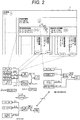
- FIG. 2 is a view illustrating a data structure, an input model, a comparison reference model, and an abstraction model of the in-model name storage unit 3 illustrated in FIG. 1 , using a recognition function of an automatic driving system as an example.
- the input model input via the in-model name storage unit 3 and the model input unit 2 the comparison reference model, and the abstraction model are illustrated in the same drawing.
- a storage area may be provided in the in-model name storage unit 3, and the comparison reference model may be stored in the storage area.
- the comparison reference model may be stored in a storage unit (not illustrated) different from the in-model name storage unit 3.
- the comparison reference model may be a model created and stored in the past or a model input via the model input unit 2.
- the case of the model input via the model input unit 2 in this manner assumes, for example, a case where a user inputs two types of models via the model input unit 2 as the models, one model is used as the input model, and the other model is used as the comparison reference model.
- the data structure of the in-model name storage unit 3 is an example of the recognition function of the automatic driving system.
- terms used in the model are names indicating functions, "recognition”, “detection”, and the like are stored in the in-model name storage unit 3 as a superlative concept (cell: R).
- "article recognition”, “object recognition”, “obstacle recognition”, and the like are stored in a subordinate concept one level below, that is, a hierarchy (cell: RO) one level below the superlative concept (cell: R).
- a subordinate concept one level below, that is, a hierarchy one level below this hierarchy stores "static article recognition”, “stationary article recognition”, “stationary object recognition”, and the like (cell: ROS), and “dynamic article recognition”, “moving body recognition”, “mobile article recognition”, and the like (cell: ROD), in the same hierarchy.
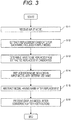
- FIG. 3 is a flowchart illustrating a processing flow of the software management device 1 illustrated in FIG. 1 .
- Step S11 the model input unit 2 constituting the software management device 1 receives a model input by the user. Note that it is assumed that the model input by the user is the input model illustrated in FIG. 2 .
- Step S12 the in-model name replacement candidate extraction unit 4 constituting the software management device 1 extracts a replacement candidate from the in-model name storage unit 3 for each name included in the model input in Step S11 described above.
- a matching name is searched for from the lowest hierarchy of the in-model name storage unit 3. If there is no matching name in the lowest hierarchy, the same search is performed in a hierarchy one level higher, and the search and an increase in level of the hierarchy to be searched are repeated until a matching name is found or no matching name is found up to the highest layer.
- the name is treated as a name that is not replaced as a unique point of the model.
- a name in the cell of the in-model name storage unit 3 including "vehicle detection”, “signal detection”, and “sign detection” constituting the input model is extracted as a candidate for a name to be replaced, for example, in FIG. 2 .
- “vehicle recognition”, “four-wheeled vehicle recognition”, “automobile recognition”, and the like stored in the same cell (RODV) are extracted as the candidates for the name to be replaced, for "vehicle detection”.
- RODV fourth-wheeled vehicle recognition
- automobile recognition and the like stored in the same cell
- ROST for “signal detection”, “signal recognition” and the like stored in the same cell (ROST) are extracted as the candidates for the name to be replaced.
- “sign recognition”, “road sign recognition”, and the like stored in the same cell (ROSS) are extracted as the candidates for the name to be replaced, for "sign detection”.
- Step S13 the in-model name determination unit 5 constituting the software management device 1 determines a name to be replaced from among the above replacement candidates obtained for the respective names included in the model input in Step S11.
- a name in the comparison reference model is referred to, and "vehicle recognition” is determined as the name to be replaced for "vehicle detection” in the in-model name storage unit 3. Since “detection” in a human-power model corresponds to "recognition” in the comparison reference model, "vehicle recognition” is determined as the name to be replaced for "vehicle detection” as described above.
- signal recognition is determined as the name to be replaced for "signal detection”
- signal recognition is determined as the name to be replaced for "sign detection”.
- the name to be replaced for the purpose of automatic model comparison and prevention of notation fluctuation may be selected as a symbol for identifying a cell as illustrated in FIG. 2 , for example, "RO" for article recognition).
- Step S14 the in-model name replacement unit 6 constituting the software management device 1 replaces each name included in the input model with the name determined in Step S13 described above.
- the in-model name replacement unit 6 constituting the software management device 1 replaces each name included in the input model with the name determined in Step S13 described above.
- “vehicle detection”, “signal detection”, and “sign detection” constituting the input model are replaced with “vehicle recognition”, “signal recognition”, and “sign recognition”, respectively.
- Step S15 the model abstraction unit 7 constituting the software management device 1 abstracts the model obtained in Step S14 described above to match an abstraction level of the comparison reference model using the hierarchical structure of the in-model name storage unit 3.
- abstraction is performed by integrating a plurality of elements having the same name in a higher hierarchy into one element (unification of the hierarchy).
- “vehicle recognition” cell RODV
- “signal recognition” cell ROST
- “sign recognition” cell ROSS
- Step S16 the model output unit 8 constituting the software management device 1 presents (displays) the converted model (model after abstraction) to the user.
- the names in the model can be automatically replaced by performing Step S12 as described above.
- the user may manually select a name to be replaced from the in-model name storage unit 3 in Step S13 when no replacement candidate is found up to the highest layer in Step S12 although it is not fully automatic.
- the software management device capable of converting the term used in the model and the abstraction level thereof.
- FIG. 4 is a functional block diagram illustrating a schematic configuration of a software management device of a second embodiment according to another embodiment of the present invention.
- the present embodiment is different from the first embodiment in that a software management device 1a is configured to further include an in-model similarity calculation unit 9.
- Other configurations are the same as those in the above-described first embodiment.
- the same components as those in the first embodiment are designated by the same reference numerals, and the description overlapping with the first embodiment will be omitted.
- the software management device 1a additionally includes the in-model name similarity calculation unit 9 in addition to the software management device 1 illustrated in the first embodiment.
- the software management device 1a according to the present embodiment is an embodiment in which the software management device 1a extracts a plurality of replacement candidates for each name included in an input model in Steps S12 and S13 in the processing flow of the software management device 1 according to the above-described first embodiment, presents the extracted replacement candidates to a user, and the user selects a name after replacement from the extracted replacement candidates.
- Step S12 the extraction of the plurality of replacement candidates is performed by calculating a similarity with a name in the model input via the model input unit 2 as, for example, a minimum edit distance for names included in the in-model name similarity calculation unit 9 in the in-model name storage unit 3, and extracting names with similarities within the top three, for example, from the replacement candidates.
- the software management device 1a it is unnecessary for the in-model name storage unit 3 to include a name that matches the name in the input model, and thus, the amount of data that needs to be stored in the in-model name storage unit 3 can be reduced.
- the software management device 1a if a similar name exists in the in-model name storage unit 3, the subsequent abstraction is possible even when the name matching the name in the input model is not included in the model name storage unit 3, and thus, the amount of data that needs to be stored in the in-model name storage unit 3 can be reduced.
- the amount of data to be stored in the in-model name storage unit 3 can be reduced as described above, in addition to the effect of the first embodiment.
- FIG. 5 is a functional block diagram illustrating a schematic configuration of a software management device of a third embodiment according to still another embodiment of the present invention
- FIG. 6 is a view illustrating a tree structure which is a data structure of an in-model name storage unit illustrated in FIG. 5
- the present embodiment is different from the first embodiment in that the structure of data stored in the in-model name storage unit 3 is the tree structure, and the in-model name replacement candidate extraction unit 4 is not required.
- Other configurations are the same as those in the above-described first embodiment.
- the same components as those in the first embodiment are designated by the same reference numerals, and the description overlapping with the first embodiment will be omitted.
- a software management device 1b includes the model input unit 2, the in-model name storage unit 3, the in-model name determination unit 5, the in-model name replacement unit 6, the model abstraction unit 7, and the model output unit 8.
- the in-model name storage unit 3 is the tree structure of categories of each element (function) described in a model as a comparison reference.
- the tree structure illustrated in FIG. 6 can be used for "recognition function" included in a model of an automatic driving system.
- the tree structure has a superlative concept of "recognition”, and a subordinate concept one level below, that is, a hierarchy one level below the superlative concept branches into “article recognition", “map recognition”, “positioning recognition”, and the like.
- a hierarchy one level below the hierarchy of "article recognition” branches into “static article recognition” and “dynamic article recognition”.
- a hierarchy one level below the hierarchy of "dynamic article recognition” that is, the lowest hierarchy branches into “vehicle recognition", “pedestrian recognition”, “animal recognition”, and the like.
- the in-model name determination unit 5 allows a user to select a name in a model after replacement using the tree structure of the in-model name storage unit 3 for each name described in the model input via the model input unit 2.
- the model input unit 2, the in-model name replacement unit 6, the model abstraction unit 7, and the model output unit 8 are the same as those in the first embodiment described above.
- FIG. 7 is a flowchart illustrating a processing flow of the software management device 1b illustrated in FIG. 5 .
- Step S21 the model input unit 2 constituting the software management device 1b receives a model input by the user.
- Step S22 the in-model name determination unit 5 constituting the software management device 1b presents the corresponding tree structure of the in-model name storage unit 3 to the user for each name included in the model input in Step S21 described above, and the user selects a name after replacement following the tree structure from a superordinate concept to a subordinate concept.
- the presentation of the tree structure to the user is realized by, for example, an interactive screen display.
- Step S23 the in-model name replacement unit 6 constituting the software management device 1b replaces each name included in the input model with the name determined in Step S22 described above.
- Step S24 the model abstraction unit 7 constituting the software management device 1b abstracts the model obtained in Step S23 described above to match an abstraction level of the comparison reference model using the hierarchies of the tree structure of the in-model name storage unit 3.
- Step S25 the model output unit 8 constituting the software management device 1b presents (displays) a converted model (model after abstraction) to the user.
- the in-model name storage unit 3 As the data structure of the tree structure as in the present embodiment. Further, the amount of data that needs to be stored in the in-model name storage unit 3 can be reduced as compared with the first embodiment described above.
- Step S15 is executed in the above-described first and second embodiments have described and the configuration in which Step S24 is executed in the third embodiment have been described, the present invention is not limited thereto.
- Steps S15 and S24 are omitted may be adopted.
- the storage unit may be created or abstracted based on a general conceptual system in this field.
- the above-described respective configurations, functions and the like may be realized by software by the processor interpreting and executing a program for realizing the respective functions.
- Information such as programs, tables, and files that realize the respective functions can be installed in a recording device such as a memory, a hard disk, and a solid state drive (SSD), or a recording medium such as an IC card, an SD card, and a DVD.
- SSD solid state drive
Landscapes
- Engineering & Computer Science (AREA)
- Theoretical Computer Science (AREA)
- Software Systems (AREA)
- General Engineering & Computer Science (AREA)
- Physics & Mathematics (AREA)
- General Physics & Mathematics (AREA)
- Computer Hardware Design (AREA)
- Computer Security & Cryptography (AREA)
- Stored Programmes (AREA)
Abstract
Description
- The present invention relates to the design and management of software and system models, and particularly to a software management device.
- In the design and management of software and systems, for example, a technique described in
PTL 1 is proposed as a technique for converting a created model. - An object of
PTL 1 is to provide a class diagram conversion device and a class diagram conversion program which support design of a class diagram with an optimum design pattern when reviewing a class diagram once created. Therefore, the class diagram conversion device identifies a pattern as an application location of class diagram conversion selected by a designer or the like based on a pattern determination logic, and displays one or more converted patterns that can be converted for the identified pattern on a display device. Then, the class diagram conversion device can convert a class diagram before conversion indicated by selection information of the application location into the pattern after conversion selected by the designer or the like and display the resultant on the display device. Accordingly, the designer or the like can select the optimum converted pattern from among one or more converted patterns displayed on the display device, and thus, the class diagram can be converted without requiring advanced knowledge about each pattern (design pattern), which is disclosed inPTL 1. - PTL 1:
JP 2014-092920 A - Since a plurality of models created by different designers have different terms and abstraction levels (depths of concept hierarchy), it is difficult to extract a difference or a common part, and it is necessary to convert the models for comparison.
- However, the technique disclosed in
PTL 1 for converting the model does not assume conversion of a term used in the model. Therefore, it is difficult to compare a plurality of models created by different designers. - Therefore, the present invention provides a software management device capable of converting a term used in a model and an abstraction level thereof.
- In order to solve the above problems, a software management device according to the present invention includes: an input unit that inputs a target model; a storage unit that hierarchically stores functions and/or names constituting the model; and an in-model name replacement unit that selects a corresponding function and/or name from the storage unit according to the input model input from the input unit, and replaces a function and/or a name in the input model with the selected function and/or name.
- According to the present invention, it is possible to provide the software management device capable of converting the term used in the model and the abstraction level thereof.
- Other objects, configurations, and effects which have not been described above become apparent from embodiments to be described hereinafter.
-
- [
FIG. 1] FIG. 1 is a functional block diagram illustrating a schematic configuration of a software management device according to a first embodiment of the present invention. - [
FIG. 2] FIG. 2 is a view illustrating a data structure, an input model, a comparison reference model, and an abstraction model of an in-model name storage unit illustrated inFIG. 1 , using a recognition function of an automatic driving system as an example. - [
FIG. 3] FIG. 3 is a flowchart illustrating a processing flow of the software management device illustrated inFIG. 1 . - [
FIG. 4] FIG. 4 is a functional block diagram illustrating a schematic configuration of a software management device of a second embodiment according to another embodiment of the present invention. - [
FIG. 5] FIG. 5 is a functional block diagram illustrating a schematic configuration of a software management device of a third embodiment according to still another embodiment of the present invention. - [
FIG. 6] FIG. 6 is a view illustrating a tree structure which is a data structure of the in-model name storage unit illustrated inFIG. 5 . - [
FIG. 7] FIG. 7 is a flowchart illustrating a processing flow of the software management device illustrated inFIG. 5 . - In the present specification, among functions and/or names constituting a model, the "name" includes the connection relationship between the respective functions included in the model or mutually transmitted and received signals.
- Further, regarding an "abstraction level", for example, when a term used in a model is a name indicating a function, a level of a hierarchy of a hierarchical structure from a subordinate concept to a superordinate concept of the function name is defined as the abstraction level. Alternatively, when a name indicating a function is stored in a tree structure, a hierarchical level of the tree is defined as the abstraction level. Note that the abstraction level is sometimes referred to as a depth of a concept hierarchy.
- Hereinafter, embodiments of the present invention will be described with reference to the drawings.
-
FIG. 1 is a functional block diagram illustrating a schematic configuration of a software management device according to a first embodiment of the present invention. As illustrated inFIG. 1 , asoftware management device 1 includes amodel input unit 2, an in-modelname storage unit 3, an in-model name replacementcandidate extraction unit 4, an in-modelname determination unit 5, an in-modelname replacement unit 6, amodel abstraction unit 7, and amodel output unit 8. Themodel input unit 2 receives an input of a model that a user desires to convert. The in-modelname storage unit 3 hierarchically stores same words and synonyms according to an abstraction level (depth of concept hierarchy) for names and/or functions of each element described in a model as a comparison reference and terms of subordinate and superordinate concepts thereof. The in-model name replacementcandidate extraction unit 4 extracts corresponding replacement candidates from the names stored in the in-modelname storage unit 3 for the names and/or functions of each element described in the model input by the user via themodel input unit 2. That is, the in-model name replacementcandidate extraction unit 4 has a function of selecting the corresponding names and/or functions as replacement candidates from the in-modelname storage unit 3 according to the input model. The in-modelname determination unit 5 determines a function and/or name to be replaced from the replacement candidates extracted by the in-model name replacementcandidate extraction unit 4. The in-modelname replacement unit 6 replaces the function and/or name in the model input via themodel input unit 2 with the function and/or name determined by the in-modelname determination unit 5. Themodel abstraction unit 7 abstracts a model abstracts performs model abstraction of the model in which the function and/or names of the described elements have been replaced in the in-modelname replacement unit 6 to a similar abstraction level with the comparison reference model using a hierarchical structure, which will be described in detail, of the in-modelname storage unit 3. Themodel output unit 8 outputs the model abstracted by themodel abstraction unit 7. - The in-model name replacement
candidate extraction unit 4, the in-modelname determination unit 5, the in-modelname replacement unit 6, and themodel abstraction unit 7 are realized by, for example, a processor such as a central processing unit (CPU) (not illustrated), a ROM that stores various programs, a RAM that temporarily stores data in an arithmetic process, and a storage device such as an external storage device. The processor such as the CPU reads and executes the various programs stored in the ROM, and stores a calculation result, which is an execution result, in the RAM or the external storage device. -
FIG. 2 is a view illustrating a data structure, an input model, a comparison reference model, and an abstraction model of the in-modelname storage unit 3 illustrated inFIG. 1 , using a recognition function of an automatic driving system as an example. In order to facilitate understanding of the description inFIG. 2 , the input model input via the in-modelname storage unit 3 and themodel input unit 2, the comparison reference model, and the abstraction model are illustrated in the same drawing. Note that, regarding the comparison reference model, a storage area may be provided in the in-modelname storage unit 3, and the comparison reference model may be stored in the storage area. Instead, the comparison reference model may be stored in a storage unit (not illustrated) different from the in-modelname storage unit 3. Further, the comparison reference model may be a model created and stored in the past or a model input via themodel input unit 2. The case of the model input via themodel input unit 2 in this manner assumes, for example, a case where a user inputs two types of models via themodel input unit 2 as the models, one model is used as the input model, and the other model is used as the comparison reference model. - As illustrated in
FIG. 2 , the data structure of the in-modelname storage unit 3 is an example of the recognition function of the automatic driving system. Thus, for example, when terms used in the model are names indicating functions, "recognition", "detection", and the like are stored in the in-modelname storage unit 3 as a superlative concept (cell: R). Further, "article recognition", "object recognition", "obstacle recognition", and the like are stored in a subordinate concept one level below, that is, a hierarchy (cell: RO) one level below the superlative concept (cell: R). A subordinate concept one level below, that is, a hierarchy one level below this hierarchy (cell: RO) stores "static article recognition", "stationary article recognition", "stationary object recognition", and the like (cell: ROS), and "dynamic article recognition", "moving body recognition", "mobile article recognition", and the like (cell: ROD), in the same hierarchy. - A subordinate concept one level below "static article recognition", "stationary article recognition", "stationary object recognition", and the like (cell: ROS), that is, the lowest hierarchy stores "signal detection" and "signal recognition, and the like (cell: ROST), and "road sign recognition", "sign detection", "sign recognition", and the like (cell: ROSS).
- A subordinate concept one level below "dynamic article recognition", "moving body recognition", "mobile article recognition", and the like (cell: ROD), that is, the lowest hierarchy stores "passer-by recognition", "human recognition", "pedestrian recognition", and the like (cell: RODP), and "four-wheeled vehicle recognition", "automobile recognition", "vehicle detection", "vehicle recognition", and the like (cell: RODV).
- Next, an operation of the
software management device 1 will be described.FIG. 3 is a flowchart illustrating a processing flow of thesoftware management device 1 illustrated inFIG. 1 . - An example applied to a model of a logical architecture of the automatic driving system will be described hereinafter.
- In Step S11, the
model input unit 2 constituting thesoftware management device 1 receives a model input by the user. Note that it is assumed that the model input by the user is the input model illustrated inFIG. 2 . - In Step S12, the in-model name replacement
candidate extraction unit 4 constituting thesoftware management device 1 extracts a replacement candidate from the in-modelname storage unit 3 for each name included in the model input in Step S11 described above. In the extraction of replacement candidates, a matching name is searched for from the lowest hierarchy of the in-modelname storage unit 3. If there is no matching name in the lowest hierarchy, the same search is performed in a hierarchy one level higher, and the search and an increase in level of the hierarchy to be searched are repeated until a matching name is found or no matching name is found up to the highest layer. Here, if no matching name is found up to the highest layer, the name is treated as a name that is not replaced as a unique point of the model. As an example of the replacement candidate extraction, a name in the cell of the in-modelname storage unit 3 including "vehicle detection", "signal detection", and "sign detection" constituting the input model is extracted as a candidate for a name to be replaced, for example, inFIG. 2 . Specifically, "vehicle recognition", "four-wheeled vehicle recognition", "automobile recognition", and the like stored in the same cell (RODV) are extracted as the candidates for the name to be replaced, for "vehicle detection". For "signal detection", "signal recognition" and the like stored in the same cell (ROST) are extracted as the candidates for the name to be replaced. Further, "sign recognition", "road sign recognition", and the like stored in the same cell (ROSS) are extracted as the candidates for the name to be replaced, for "sign detection". - In Step S13, the in-model
name determination unit 5 constituting thesoftware management device 1 determines a name to be replaced from among the above replacement candidates obtained for the respective names included in the model input in Step S11. For example, inFIG. 2 , a name in the comparison reference model is referred to, and "vehicle recognition" is determined as the name to be replaced for "vehicle detection" in the in-modelname storage unit 3. Since "detection" in a human-power model corresponds to "recognition" in the comparison reference model, "vehicle recognition" is determined as the name to be replaced for "vehicle detection" as described above. Similarly, "signal recognition" is determined as the name to be replaced for "signal detection", and "sign recognition" is determined as the name to be replaced for "sign detection". Note that the name to be replaced for the purpose of automatic model comparison and prevention of notation fluctuation may be selected as a symbol for identifying a cell as illustrated inFIG. 2 , for example, "RO" for article recognition). - In Step S14, the in-model
name replacement unit 6 constituting thesoftware management device 1 replaces each name included in the input model with the name determined in Step S13 described above. For example, inFIG. 2 , "vehicle detection", "signal detection", and "sign detection" constituting the input model are replaced with "vehicle recognition", "signal recognition", and "sign recognition", respectively. - In Step S15, the
model abstraction unit 7 constituting thesoftware management device 1 abstracts the model obtained in Step S14 described above to match an abstraction level of the comparison reference model using the hierarchical structure of the in-modelname storage unit 3. As illustrated inFIG. 2 , for example, in the hierarchical structure of the in-modelname storage unit 3, abstraction is performed by integrating a plurality of elements having the same name in a higher hierarchy into one element (unification of the hierarchy). For example, inFIG. 2 , in the input model in which names have been replaced, "vehicle recognition" (cell RODV), "signal recognition" (cell ROST), and "sign recognition" (cell ROSS) are abstracted as "article recognition" (cell RO) in a higher hierarchy of these. As a result, for example, it is possible to unify the abstraction level of two models having different abstraction levels in which the number of logical functions is remarkably different, and it is possible to extract a common part and a difference from the above two models. - In Step S16, the
model output unit 8 constituting thesoftware management device 1 presents (displays) the converted model (model after abstraction) to the user. - Note that the names in the model can be automatically replaced by performing Step S12 as described above. On the other hand, the user may manually select a name to be replaced from the in-model
name storage unit 3 in Step S13 when no replacement candidate is found up to the highest layer in Step S12 although it is not fully automatic. - Further, the replacement of the name has been described in the present embodiment, but a function constituting a model may be replaced, or the function constituting the model and a name of each element may be replaced without being limited to the replacement of the name.
- As described above, according to the present embodiment, it is possible to provide the software management device capable of converting the term used in the model and the abstraction level thereof.
-
FIG. 4 is a functional block diagram illustrating a schematic configuration of a software management device of a second embodiment according to another embodiment of the present invention. The present embodiment is different from the first embodiment in that a software management device 1a is configured to further include an in-modelsimilarity calculation unit 9. Other configurations are the same as those in the above-described first embodiment. Hereinafter, the same components as those in the first embodiment are designated by the same reference numerals, and the description overlapping with the first embodiment will be omitted. - As illustrated in
FIG. 4 , the software management device 1a additionally includes the in-model namesimilarity calculation unit 9 in addition to thesoftware management device 1 illustrated in the first embodiment. The software management device 1a according to the present embodiment is an embodiment in which the software management device 1a extracts a plurality of replacement candidates for each name included in an input model in Steps S12 and S13 in the processing flow of thesoftware management device 1 according to the above-described first embodiment, presents the extracted replacement candidates to a user, and the user selects a name after replacement from the extracted replacement candidates. In Step S12, the extraction of the plurality of replacement candidates is performed by calculating a similarity with a name in the model input via themodel input unit 2 as, for example, a minimum edit distance for names included in the in-model namesimilarity calculation unit 9 in the in-modelname storage unit 3, and extracting names with similarities within the top three, for example, from the replacement candidates. In the software management device 1a according to the present embodiment, it is unnecessary for the in-modelname storage unit 3 to include a name that matches the name in the input model, and thus, the amount of data that needs to be stored in the in-modelname storage unit 3 can be reduced. In other words, in the software management device 1a according to the present embodiment, if a similar name exists in the in-modelname storage unit 3, the subsequent abstraction is possible even when the name matching the name in the input model is not included in the modelname storage unit 3, and thus, the amount of data that needs to be stored in the in-modelname storage unit 3 can be reduced. - According to the present embodiment, the amount of data to be stored in the in-model
name storage unit 3 can be reduced as described above, in addition to the effect of the first embodiment. -
FIG. 5 is a functional block diagram illustrating a schematic configuration of a software management device of a third embodiment according to still another embodiment of the present invention, andFIG. 6 is a view illustrating a tree structure which is a data structure of an in-model name storage unit illustrated inFIG. 5 . The present embodiment is different from the first embodiment in that the structure of data stored in the in-modelname storage unit 3 is the tree structure, and the in-model name replacementcandidate extraction unit 4 is not required. Other configurations are the same as those in the above-described first embodiment. Hereinafter, the same components as those in the first embodiment are designated by the same reference numerals, and the description overlapping with the first embodiment will be omitted. - As illustrated in
FIG. 5 , asoftware management device 1b according to the present embodiment includes themodel input unit 2, the in-modelname storage unit 3, the in-modelname determination unit 5, the in-modelname replacement unit 6, themodel abstraction unit 7, and themodel output unit 8. The in-modelname storage unit 3 is the tree structure of categories of each element (function) described in a model as a comparison reference. For example, the tree structure illustrated inFIG. 6 can be used for "recognition function" included in a model of an automatic driving system. As illustrated inFIG. 6 , the tree structure has a superlative concept of "recognition", and a subordinate concept one level below, that is, a hierarchy one level below the superlative concept branches into "article recognition", "map recognition", "positioning recognition", and the like. A hierarchy one level below the hierarchy of "article recognition" branches into "static article recognition" and "dynamic article recognition". Further, a hierarchy one level below the hierarchy of "dynamic article recognition", that is, the lowest hierarchy branches into "vehicle recognition", "pedestrian recognition", "animal recognition", and the like. The in-modelname determination unit 5 allows a user to select a name in a model after replacement using the tree structure of the in-modelname storage unit 3 for each name described in the model input via themodel input unit 2. Themodel input unit 2, the in-modelname replacement unit 6, themodel abstraction unit 7, and themodel output unit 8 are the same as those in the first embodiment described above. - Next, an operation of the
software management device 1b will be described.FIG. 7 is a flowchart illustrating a processing flow of thesoftware management device 1b illustrated inFIG. 5 . - In Step S21, the
model input unit 2 constituting thesoftware management device 1b receives a model input by the user. - In Step S22, the in-model
name determination unit 5 constituting thesoftware management device 1b presents the corresponding tree structure of the in-modelname storage unit 3 to the user for each name included in the model input in Step S21 described above, and the user selects a name after replacement following the tree structure from a superordinate concept to a subordinate concept. Here, the presentation of the tree structure to the user is realized by, for example, an interactive screen display. - In Step S23, the in-model
name replacement unit 6 constituting thesoftware management device 1b replaces each name included in the input model with the name determined in Step S22 described above. - In Step S24, the
model abstraction unit 7 constituting thesoftware management device 1b abstracts the model obtained in Step S23 described above to match an abstraction level of the comparison reference model using the hierarchies of the tree structure of the in-modelname storage unit 3. - In Step S25, the
model output unit 8 constituting thesoftware management device 1b presents (displays) a converted model (model after abstraction) to the user. - Note that it becomes easy to perform subsequent analysis work of the model, for example, categorization or grouping of elements in the model, by forming the in-model
name storage unit 3 as the data structure of the tree structure as in the present embodiment. Further, the amount of data that needs to be stored in the in-modelname storage unit 3 can be reduced as compared with the first embodiment described above. - According to the present embodiment, it is possible to facilitate the subsequent analysis work of the model such as categorization and grouping of elements in the model as described above, in addition to the effect of the first embodiment.
- Note that the configuration in which Step S15 is executed in the above-described first and second embodiments have described and the configuration in which Step S24 is executed in the third embodiment have been described, the present invention is not limited thereto.
- A configuration in which these Steps S15 and S24 are omitted may be adopted.
- Further, the configuration in which the comparison reference model is set has been described in the above-described first, second, and third embodiments, but the present invention is not limited thereto. For example, the storage unit may be created or abstracted based on a general conceptual system in this field.
- Note that the present invention is not limited to the above-described embodiments, but includes various modifications.
- For example, the above-described embodiments have been described in detail in order to describe the present invention in an easily understandable manner, and are not necessarily limited to one including the entire configuration that has been described above. Further, some configurations of a certain embodiment can be substituted by configurations of another embodiment, and further, a configuration of another embodiment can be also added to a configuration of a certain embodiment. Further, addition, deletion or substitution of other configurations can be made with respect to some configurations of each embodiment. Further, a part or all of each of the above-described configurations, functions, processing units, processing means, and the like may be realized, for example, by hardware by designing with an integrated circuit and the like. Further, the above-described respective configurations, functions and the like may be realized by software by the processor interpreting and executing a program for realizing the respective functions. Information such as programs, tables, and files that realize the respective functions can be installed in a recording device such as a memory, a hard disk, and a solid state drive (SSD), or a recording medium such as an IC card, an SD card, and a DVD.
-
- 1, 1a, 1b
- software management device
- 2
- model input unit
- 3
- in-model name storage unit
- 4
- in-model name replacement candidate extraction unit
- 5
- in-model name determination unit
- 6
- in-model name replacement unit
- 7
- model abstraction unit
- 8
- model output unit
- 9
- in-model similarity calculation unit
Claims (9)
- A software management device comprising:an input unit that inputs a target model;a storage unit that hierarchically stores functions and/or names constituting the model; andan in-model name replacement unit that selects a corresponding function and/or name from the storage unit according to the input model input from the input unit, and replaces a function and/or a name in the input model with the selected function and/or name.
- The software management device according to claim 1, further comprising
a model abstraction unit that abstracts the input model based on the function and/or name replaced by the in-model name replacement unit and hierarchical levels of the functions and/or names constituting the model hierarchically stored in the storage unit. - The software management device according to claim 2, further comprising
an in-model name determination unit that selects a function and/or a name constituting the model stored in the storage unit which match a function and/or a name constituting the input model input from the input unit. - The software management device according to claim 1, wherein
the storage unit stores the functions and/or names constituting the model so as to include synonyms and hierarchize hierarchy levels of a hierarchical structure from a subordinate concept to a superordinate concept according to an abstraction level. - The software management device according to claim 1, wherein
the storage unit stores functions and/or names constituting a model as a tree structure of categories, and sets a hierarchical level of a tree as an abstraction level. - The software management device according to claim 2, further comprising
an in-model name replacement candidate extraction unit that extracts a plurality of replacement candidates from the storage unit for the function and/or name constituting the input model input from the input unit. - The software management device according to claim 6, further comprising
an in-model similarity calculation unit that obtains a similarity between a function and/or a name that constitutes the input model input from the input unit and a function and/or a name that constitutes the model stored in the storage unit. - The software management device according to claim 3, wherein
the storage unit stores the functions and/or names constituting the model so as to include synonyms and hierarchize hierarchy levels of a hierarchical structure from a subordinate concept to a superordinate concept according to an abstraction level. - The software management device according to claim 3, wherein
the storage unit stores functions and/or names constituting a model as a tree structure of categories, and sets a hierarchical level of a tree as the abstraction level.
Applications Claiming Priority (2)
| Application Number | Priority Date | Filing Date | Title |
|---|---|---|---|
| JP2018206377 | 2018-11-01 | ||
| PCT/JP2019/040566 WO2020090454A1 (en) | 2018-11-01 | 2019-10-16 | Software management device |
Publications (2)
| Publication Number | Publication Date |
|---|---|
| EP3851954A1 true EP3851954A1 (en) | 2021-07-21 |
| EP3851954A4 EP3851954A4 (en) | 2022-06-22 |
Family
ID=70462355
Family Applications (1)
| Application Number | Title | Priority Date | Filing Date |
|---|---|---|---|
| EP19880642.4A Pending EP3851954A4 (en) | 2018-11-01 | 2019-10-16 | SOFTWARE MANAGEMENT DEVICE |
Country Status (5)
| Country | Link |
|---|---|
| US (1) | US11763035B2 (en) |
| EP (1) | EP3851954A4 (en) |
| JP (1) | JP7110385B2 (en) |
| CN (1) | CN112912839B (en) |
| WO (1) | WO2020090454A1 (en) |
Family Cites Families (18)
| Publication number | Priority date | Publication date | Assignee | Title |
|---|---|---|---|---|
| JPH0650778A (en) | 1992-06-05 | 1994-02-25 | Toshiba Corp | Plant preventive maintenance information management device and management method |
| JPH07121372A (en) * | 1993-10-20 | 1995-05-12 | Hitachi Ltd | Class inheritance relationship derivation system |
| US7334216B2 (en) * | 2000-04-04 | 2008-02-19 | Sosy, Inc. | Method and apparatus for automatic generation of information system user interfaces |
| US7934194B2 (en) * | 2006-10-17 | 2011-04-26 | The Mathworks, Inc. | User-defined hierarchies of user-defined classes of graphical objects in a graphical modeling environment |
| US20080244736A1 (en) * | 2007-03-30 | 2008-10-02 | Microsoft Corporation | Model-based access control |
| EP2223282A4 (en) * | 2007-12-20 | 2011-11-16 | Hewlett Packard Development Co | Automated model generation for computer based business process |
| JP5401942B2 (en) | 2008-11-17 | 2014-01-29 | 富士通株式会社 | Function name calibration device and function name calibration program |
| CN101777071A (en) * | 2010-01-08 | 2010-07-14 | 华中师范大学 | Term marking system for constructing educational technology field ontology library |
| US8266186B2 (en) * | 2010-04-30 | 2012-09-11 | International Business Machines Corporation | Semantic model association between data abstraction layer in business intelligence tools |
| JP2012059026A (en) * | 2010-09-09 | 2012-03-22 | Hitachi Ltd | Source code conversion method and source code conversion program |
| JP5323107B2 (en) * | 2011-02-10 | 2013-10-23 | 三菱電機株式会社 | Software component management apparatus and software component management program |
| JP5952716B2 (en) | 2012-11-02 | 2016-07-13 | 日本電信電話株式会社 | Class diagram conversion device and class diagram conversion program |
| US10268709B1 (en) * | 2013-03-08 | 2019-04-23 | Datical, Inc. | System, method and computer program product for database change management |
| CN103207856B (en) * | 2013-04-03 | 2015-10-28 | 同济大学 | A kind of Ontological concept and hierarchical relationship generation method |
| JP2014241056A (en) | 2013-06-12 | 2014-12-25 | 株式会社日立製作所 | Specification correction support method and specification correction support system |
| US9158503B2 (en) * | 2013-10-08 | 2015-10-13 | King Fahd University Of Petroleum And Minerals | UML model integration and refactoring method |
| US9563771B2 (en) * | 2014-01-22 | 2017-02-07 | Object Security LTD | Automated and adaptive model-driven security system and method for operating the same |
| US10209974B1 (en) * | 2017-12-04 | 2019-02-19 | Banjo, Inc | Automated model management methods |
-
2019
- 2019-10-16 JP JP2020553753A patent/JP7110385B2/en active Active
- 2019-10-16 EP EP19880642.4A patent/EP3851954A4/en active Pending
- 2019-10-16 WO PCT/JP2019/040566 patent/WO2020090454A1/en not_active Ceased
- 2019-10-16 CN CN201980067132.7A patent/CN112912839B/en active Active
- 2019-10-16 US US17/290,456 patent/US11763035B2/en active Active
Also Published As
| Publication number | Publication date |
|---|---|
| US20220035954A1 (en) | 2022-02-03 |
| JP7110385B2 (en) | 2022-08-01 |
| CN112912839B (en) | 2024-06-21 |
| WO2020090454A1 (en) | 2020-05-07 |
| CN112912839A (en) | 2021-06-04 |
| JPWO2020090454A1 (en) | 2021-09-02 |
| EP3851954A4 (en) | 2022-06-22 |
| US11763035B2 (en) | 2023-09-19 |
Similar Documents
| Publication | Publication Date | Title |
|---|---|---|
| US10664660B2 (en) | Method and device for extracting entity relation based on deep learning, and server | |
| AU2019210601B2 (en) | Automatic generation of microservices based on technical description of legacy code | |
| US10929439B2 (en) | Taxonomic tree generation | |
| EP4024263A1 (en) | Method for dynamic maintenance of a knowledge graph, terminal device and storage medium | |
| US10628632B2 (en) | Generating a structured document based on a machine readable document and artificial intelligence-generated annotations | |
| JP2015532991A (en) | Modernization of legacy software systems based on modeled dependencies | |
| US10706030B2 (en) | Utilizing artificial intelligence to integrate data from multiple diverse sources into a data structure | |
| US20130054427A1 (en) | Explosions of bill-of-materials lists | |
| CN113918576B (en) | Metadata management platform and management method | |
| KR102520305B1 (en) | Deep learning document analysis system and method based on keyword frequency and section centrality analysis | |
| US20200387505A1 (en) | Information processing system, feature description method and feature description program | |
| CN112507660A (en) | Method and system for determining homology and displaying difference of compound document | |
| JP7814182B2 (en) | Data processing device, data processing method and data processing program | |
| US11763035B2 (en) | Software management device | |
| US10909021B2 (en) | Assistance device, design assistance method, and recording medium storing design assistance program | |
| US8522175B2 (en) | Semiconductor circuit design supporting apparatus and method, and non-transitory computer-readable medium | |
| EP3447638A1 (en) | Template generating device, template generating program, and template generating method | |
| WO2024047997A1 (en) | Document analysis device and program for document analysis | |
| JP6535591B2 (en) | Image recognition apparatus and operation method of image recognition apparatus | |
| van Deursen et al. | Finding classes in legacy code using cluster analysis | |
| US20250061135A1 (en) | Information processing apparatus, information processing method, and storage medium | |
| JP7664190B2 (en) | Information processing device, information processing system, and information processing method | |
| JP7248801B2 (en) | Design support system and design support method | |
| US10896272B2 (en) | High-level synthesis device, high-level synthesis method, and computer readable medium | |
| Wiedenhoeft et al. | Using HaMMLET for Bayesian Segmentation of WGS Read-Depth Data |
Legal Events
| Date | Code | Title | Description |
|---|---|---|---|
| STAA | Information on the status of an ep patent application or granted ep patent |
Free format text: STATUS: THE INTERNATIONAL PUBLICATION HAS BEEN MADE |
|
| PUAI | Public reference made under article 153(3) epc to a published international application that has entered the european phase |
Free format text: ORIGINAL CODE: 0009012 |
|
| STAA | Information on the status of an ep patent application or granted ep patent |
Free format text: STATUS: REQUEST FOR EXAMINATION WAS MADE |
|
| 17P | Request for examination filed |
Effective date: 20210416 |
|
| AK | Designated contracting states |
Kind code of ref document: A1 Designated state(s): AL AT BE BG CH CY CZ DE DK EE ES FI FR GB GR HR HU IE IS IT LI LT LU LV MC MK MT NL NO PL PT RO RS SE SI SK SM TR |
|
| DAV | Request for validation of the european patent (deleted) | ||
| DAX | Request for extension of the european patent (deleted) | ||
| A4 | Supplementary search report drawn up and despatched |
Effective date: 20220519 |
|
| RIC1 | Information provided on ipc code assigned before grant |
Ipc: G06F 8/35 20180101ALI20220513BHEP Ipc: G06F 8/70 20180101ALI20220513BHEP Ipc: G06F 8/20 20180101AFI20220513BHEP |
|
| STAA | Information on the status of an ep patent application or granted ep patent |
Free format text: STATUS: EXAMINATION IS IN PROGRESS |
|
| 17Q | First examination report despatched |
Effective date: 20230217 |
|
| RAP3 | Party data changed (applicant data changed or rights of an application transferred) |
Owner name: ASTEMO, LTD. |