EP3851928A1 - A system for data transmission between a client device, a server device and a plurality of automation devices - Google Patents
A system for data transmission between a client device, a server device and a plurality of automation devices Download PDFInfo
- Publication number
- EP3851928A1 EP3851928A1 EP20152429.5A EP20152429A EP3851928A1 EP 3851928 A1 EP3851928 A1 EP 3851928A1 EP 20152429 A EP20152429 A EP 20152429A EP 3851928 A1 EP3851928 A1 EP 3851928A1
- Authority
- EP
- European Patent Office
- Prior art keywords
- server
- automation
- client
- opc
- automation devices
- Prior art date
- Legal status (The legal status is an assumption and is not a legal conclusion. Google has not performed a legal analysis and makes no representation as to the accuracy of the status listed.)
- Granted
Links
- 230000005540 biological transmission Effects 0.000 title claims abstract description 7
- 238000000034 method Methods 0.000 claims description 28
- 238000004891 communication Methods 0.000 claims description 21
- 238000012544 monitoring process Methods 0.000 claims description 3
- 230000008569 process Effects 0.000 description 13
- 238000005516 engineering process Methods 0.000 description 5
- 230000008859 change Effects 0.000 description 4
- 230000000694 effects Effects 0.000 description 4
- 230000003993 interaction Effects 0.000 description 4
- 238000004519 manufacturing process Methods 0.000 description 4
- 230000007246 mechanism Effects 0.000 description 4
- 230000008901 benefit Effects 0.000 description 3
- 238000011161 development Methods 0.000 description 2
- 238000004870 electrical engineering Methods 0.000 description 2
- 230000006870 function Effects 0.000 description 2
- 230000006872 improvement Effects 0.000 description 2
- 238000012423 maintenance Methods 0.000 description 2
- 238000007726 management method Methods 0.000 description 2
- 238000011089 mechanical engineering Methods 0.000 description 2
- 238000004886 process control Methods 0.000 description 2
- 230000004044 response Effects 0.000 description 2
- 238000012546 transfer Methods 0.000 description 2
- 238000012800 visualization Methods 0.000 description 2
- 230000003044 adaptive effect Effects 0.000 description 1
- 230000004931 aggregating effect Effects 0.000 description 1
- 239000010779 crude oil Substances 0.000 description 1
- 238000013499 data model Methods 0.000 description 1
- 230000008030 elimination Effects 0.000 description 1
- 238000003379 elimination reaction Methods 0.000 description 1
- 230000000977 initiatory effect Effects 0.000 description 1
- 230000010354 integration Effects 0.000 description 1
- 239000000543 intermediate Substances 0.000 description 1
- 238000013507 mapping Methods 0.000 description 1
- 239000000463 material Substances 0.000 description 1
- 230000008450 motivation Effects 0.000 description 1
- 230000006855 networking Effects 0.000 description 1
- 239000003921 oil Substances 0.000 description 1
- 230000000737 periodic effect Effects 0.000 description 1
- 239000008238 pharmaceutical water Substances 0.000 description 1
- 230000009467 reduction Effects 0.000 description 1
- 238000007670 refining Methods 0.000 description 1
- 230000003068 static effect Effects 0.000 description 1
- 239000000126 substance Substances 0.000 description 1
- 238000013519 translation Methods 0.000 description 1
- 238000004065 wastewater treatment Methods 0.000 description 1
Images


Classifications
-
- H—ELECTRICITY
- H04—ELECTRIC COMMUNICATION TECHNIQUE
- H04L—TRANSMISSION OF DIGITAL INFORMATION, e.g. TELEGRAPHIC COMMUNICATION
- H04L41/00—Arrangements for maintenance, administration or management of data switching networks, e.g. of packet switching networks
- H04L41/08—Configuration management of networks or network elements
- H04L41/0866—Checking the configuration
- H04L41/0869—Validating the configuration within one network element
-
- G—PHYSICS
- G05—CONTROLLING; REGULATING
- G05B—CONTROL OR REGULATING SYSTEMS IN GENERAL; FUNCTIONAL ELEMENTS OF SUCH SYSTEMS; MONITORING OR TESTING ARRANGEMENTS FOR SUCH SYSTEMS OR ELEMENTS
- G05B19/00—Programme-control systems
- G05B19/02—Programme-control systems electric
- G05B19/418—Total factory control, i.e. centrally controlling a plurality of machines, e.g. direct or distributed numerical control [DNC], flexible manufacturing systems [FMS], integrated manufacturing systems [IMS], computer integrated manufacturing [CIM]
- G05B19/4185—Total factory control, i.e. centrally controlling a plurality of machines, e.g. direct or distributed numerical control [DNC], flexible manufacturing systems [FMS], integrated manufacturing systems [IMS], computer integrated manufacturing [CIM] characterised by the network communication
-
- G—PHYSICS
- G06—COMPUTING; CALCULATING OR COUNTING
- G06N—COMPUTING ARRANGEMENTS BASED ON SPECIFIC COMPUTATIONAL MODELS
- G06N20/00—Machine learning
-
- H—ELECTRICITY
- H04—ELECTRIC COMMUNICATION TECHNIQUE
- H04L—TRANSMISSION OF DIGITAL INFORMATION, e.g. TELEGRAPHIC COMMUNICATION
- H04L61/00—Network arrangements, protocols or services for addressing or naming
- H04L61/30—Managing network names, e.g. use of aliases or nicknames
- H04L61/3015—Name registration, generation or assignment
-
- H—ELECTRICITY
- H04—ELECTRIC COMMUNICATION TECHNIQUE
- H04L—TRANSMISSION OF DIGITAL INFORMATION, e.g. TELEGRAPHIC COMMUNICATION
- H04L61/00—Network arrangements, protocols or services for addressing or naming
- H04L61/45—Network directories; Name-to-address mapping
- H04L61/4505—Network directories; Name-to-address mapping using standardised directories; using standardised directory access protocols
- H04L61/4511—Network directories; Name-to-address mapping using standardised directories; using standardised directory access protocols using domain name system [DNS]
-
- H—ELECTRICITY
- H04—ELECTRIC COMMUNICATION TECHNIQUE
- H04L—TRANSMISSION OF DIGITAL INFORMATION, e.g. TELEGRAPHIC COMMUNICATION
- H04L69/00—Network arrangements, protocols or services independent of the application payload and not provided for in the other groups of this subclass
- H04L69/22—Parsing or analysis of headers
-
- G—PHYSICS
- G05—CONTROLLING; REGULATING
- G05B—CONTROL OR REGULATING SYSTEMS IN GENERAL; FUNCTIONAL ELEMENTS OF SUCH SYSTEMS; MONITORING OR TESTING ARRANGEMENTS FOR SUCH SYSTEMS OR ELEMENTS
- G05B2219/00—Program-control systems
- G05B2219/30—Nc systems
- G05B2219/34—Director, elements to supervisory
- G05B2219/34263—OLE object linking and embedding, OPC ole for process control
Definitions
- the present invention relates to automation technology.
- Automation technology is a branch of engineering, which mainly relates to mechanical engineering and electrical engineering. It is used to automate technical processes in machines, plants or technical systems in general.
- Automation systems which are used in a variety of industries such as chemical, pharmaceutical, and wastewater treatment, oversee devices performing a process that creates or changes something by performing that process; for instance, in oil refining, process control systems oversee the machinery and devices that transform crude oil into gasoline.
- a process control system is generally comprised of three groups of electronic devices: controllers, input/output ("I/O") devices, and automation devices. Automation devices send information about process activities to controllers through the I/O system, and the controller in turn sends information to other field devices to make adjustments to process activities.
- automation systems are involved in the physical and organizational structures and facilities used in the production of goods, such as products, procedures, building (or group of buildings), networks, controllers, interfaces, machinery, and assembly lines.
- PROFINET, Ethernet IP or Modbus-TCP are examples of Ethernet-based communication mechanisms.
- a communication mechanism is usually defined by the associated protocol, normally standardized, and the communication relationship on which it is based. Communication relationships organize communication between the devices participating in data transmission in the network, also known as users. Examples of communication relationships are client/server, master/slave, master/master, producer/consumer or publisher/subscriber.
- TCP/IP is frequently used as the communication protocol for Ethernet- based networks. It is envisioned to replace the IP-based communication components through a pure Ethernet (Layer-2) communication. Omitting the IP stack would allow production of cheaper devices than previously possible for devices with IP stack.
- IP-less automation devices appear like automation devices that possess an IP stack.
- the user should be concealed to the user, e.g., of a client application, whether the respective automation device possess an IP stack or not. Rather, the user, e.g., via said client application, should be able to address all devices via IP.
- the user may then communicate with (IP-less) automation devices via IP just as with other automation devices that possess an OPC UA server and IP-capabilities.
- NAT Network Address Translation
- ALG application layer gateways
- Proxies - and in particular web proxies - are, in addition to other tasks, used to provide client applications with a single application server and thus a single access point ("portal"), although there are actually several application servers behind the proxy, cf. Section 2.3, "Intermediates” in RFC 7230, "Hypertext Transfer Protocol (HTTP/1.1): Message Syntax and Routing”. Similar to proxies, HTTP itself offers a function for dividing an application server into several logical application servers, in the form of the so-called “virtual hosts” - see RFC 7230, “Hypertext Transfer Protocol (HTTP/1.1): Message Syntax and Routing".
- the present invention provides improvements and solutions to the situation described in the above.
- a system for data transmission between a client device, a server device and a plurality of automation devices comprising a descriptive representation of each of the plurality of automation devices, wherein the server device comprises a server instance, which server instance is operative to load one of the descriptive representations based on a hostname identifying one of the plurality of automation devices, and wherein the server instance is operative to transmit data from the automation device to a client application on the client device based on the loaded descriptive representation of the automation device.
- a server device According to a second aspect a server device according to the first aspect is proposed.
- a client device According to a third aspect a client device according to the first aspect is proposed.
- a method for data transmission between a client device, a server device and one or more automation devices comprising a descriptive representation of each the plurality of automation devices, wherein the server device comprises a server instance, comprising the steps of: loading, by the server instance, one of the descriptive representations based on a hostname identifying one of the plurality of automation devices, and transmitting, by the server instance, data from the automation device to a client application on the client device.
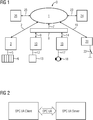
- FIG 1 shows an automation system 0 comprising automation devices 6, 13, 17, 22 and different web servers 3, 10, 15, 20, 24 which are connected to one another directly or indirectly via the internet 1.
- Automation technology is a sub-area of plant engineering and engineering that mainly affects mechanical engineering and electrical engineering. It is used to automate technical processes in machines, plants or technical systems in general.
- a first web server 3 communicates directly with the internet 1 via a connection 2.
- the first web server 3 is connected via a connection 5 to an input/output module 6 of an automation system.
- a second and a third web server 10, 15 are connected to the internet 1 via connections 9, 14, a firewall 8 and a connection 7.
- the second web server 10 has a connection 12 to a converter 13.
- the third web server 15 has a connection 17 with a drive 18.
- the reference numeral 20 identifies a fourth web server, referred to as an embedded web server, which is connected directly to the internet 1 via a connection 19 and which is embedded in a control of a valve 22.
- the fifth web server 24 shown in FIG. 1 possesses no automation functionality and communicates with the internet via a connection 23.
- a client 26, such as a web browser is connected to the internet 1 via a connection 25.
- a webserver may be communicatively coupled with an automation device. To this end, the webserver can be embedded in the automation device.
- a web server is a process running on a computer-or also distributed over a plurality of computers and typically supplies one or more clients (web browsers on different devices) with information. This information can either reside statically on the web server or else be generated dynamically by further utility routines.
- Typical communication partners connected via the internet 1 are therefore web servers in the embodiment of the fifth web server 24 and client 26.
- the fifth web server 24 provides information, generally internet pages, via the internet 1 in response to a request from a client 26.
- a web server may be connected via a connection and a TCP/IP stack. Further details regarding the use of web servers in the field of automation technology are for example disclosed in US patent application US2005198137A1 .
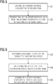
- FIG. 2 illustrates an arrangement for interaction between a client and a server.
- a client and a server may be collocated on a single device but may also be located on separate devices.
- an OPC UA client and an OPC UA server according to the OPC UA specification using a communication system, such as a network are shown.
- the OPC UA client uses OPC UA service calls from a set of OPC UA service calls specified in the OPC UA protocol for interaction.
- the field of application for OPC UA clients and servers encompasses a wide range and their function can be implemented in different automation devices and automation systems, such as controllers, PC-based control systems, production management systems, or in production planning, for example.
- OPC UA clients and OPC UA servers and other specifics of the OPC UA protocol and/or OPC UA standard this is for exemplary purposes only and the scope and spirit of the invention is not limited to OPC UA only but may apply to other protocols and standards as well.
- OPC UA uses a similar client-server concept like classic OPC.
- An application that wants to expose its own information to other applications is called UA server and an application that wants to consume information from other applications is called UA client.
- UA server An application that wants to expose its own information to other applications
- UA client an application that wants to consume information from other applications
- OPC client it is expected that much more applications will be both UA server and UA client in one application than in classic OPC.
- One reason is that more UA servers will be integrated directly in devices.
- Implementing also a UA client enables device to device communication.
- Another reason is the use of OPC UA as configuration interface, where UA clients are also UA servers to be configured via OPC UA.
- a typical OPC UA application is composed of three software layers shown in the following figure.
- the complete software stack can be implemented with C/C++, .NET, or JAVA.
- OPC UA is not limited to these programming languages and development platforms, but only these environments are currently used for implementing the OPC Foundation UA Stack deliverables.
- the OPC-UA (web) server is used for the visualization, monitoring and control of processes. By using the web technology, all variables of a process are always available at any place and via any conventional web browser.
- the OPC-UA web server may be provided in the form of a library that is loaded and executed by a runtime environment.
- the OPC UA web server has an OPC UA client interface for accessing the variables of a process.
- the visualization may be created with the OPC-UA-Designer based on HTML5 and uploaded to the OPC-UA web server via an OPC-UA server interface.
- An OPC UA application is a system that wants to expose or to consume data via OPC UA. It contains the specific functionality for the application and the mapping of this functionality to OPC UA by using an OPC UA Stack and an OPC UA Software Development Kit (SDK).
- SDK Software Development Kit
- An OPC UA client or server SDK implements common OPC UA functionality that is part of the application layer, since the UA Stacks implement only the communication channels.
- An OPC UA SDK reduces the development effort and facilitates faster interoperability for an OPC UA application.
- the Address Space Model in UA Part 3 specifies the building blocks to expose instance and type information and thus the OPC UA meta model used to describe and expose information models and to build an OPC UA server address space.
- the abstract UA Services defined in UA Part 4 represent the possible interactions between UA client and UA server applications.
- the client uses the Services to find and access information provided by the server.
- the so called DA (Data Access) information model defines automation-data-specific extensions such as the modeling of analog or discrete data and how to expose quality of service. All other DA features are already covered by the base services.
- the Alarm & Conditions (AC) information model specifies an advanced model for process alarm management and condition monitoring.
- the Historical Access (HA) information model defines the mechanisms to access historical data and historical events.
- the Programs (Prog) information model specifies a mechanism to start, manipulate, and monitor the execution of programs.
- the base information model specified in UA Part 5 provides the framework for all information models using OPC UA. It defines the following:
- OPC UA defines a set of discovery features.
- a server can provide several endpoints, each containing:
- a Discovery Server can be used to provide information of available servers. Servers can register at the Discovery Server. Clients may then request a list of all available servers from the discovery server and then use the GetEndpoints service to get connection information from a server.
- the TCP/IP stack is a set of networking protocols.
- the OSI Model was meant to be a standardized way of connecting devices together, and most protocols have some direct correlation to the OSI Model.
- the OSI Model has 7 layers, the TCP/IP stack which is the most common Protocol suite in use today has 4.
- the Internet Protocol layer in the TCP/IP protocol stack is the first layer that introduces the virtual network abstraction that is the basic principle of the Internet model.
- OPC UA Today, the OPC UA standard provides a host communication parameter that is transmitted by OPC UA clients and which, according to the text of the OPC UA standards ("OPC UA Part 4 Services"), is used to ensure that a client signals the host name and thus which server network interface the client addresses when communicating with an OPC UA Server.
- a PLC may have multiple IP network interfaces, but individual network interfaces may only be reached from certain sub-nets, so that users must have detailed network topological knowledge in order to have successfully address OPC UA Server.
- the addressed host name is included as part of the so-called endpointUrl parameter, which a client uses in its request to the GetEndpoints service. Due to the lack of network continuity the service uses the host name to filter its response, so that only those endpointUrls are transmitted to the client that it can actually reach.
- the host communication parameter is used when setting up a OPC UA server session using the CreateSession service. In that case the client reenters the server endpoint it actually addresses in the form of an endpointUrl parameter.
- the automation system 0 comprising a client device 110, a server device 100 and multiple automation devices 101a, 101b.
- the automation system 0 comprising a client device 110, a server device 100 and multiple automation devices 101a, 101b.
- OPC UA standard is made for exemplary purposes and one or more other standards for an operating an automation system 0 may be used.
- an OPC UA client 110 interoperates with an OPC UA server 112, e.g., wherein the server 112 is located on a server device, such as a PLC 100, as if this server appears to be on each individual automation device 101a and 101b, respectively.
- the device-specific information models, cf. 123a, 123b in Figure 4 of the individual automation devices 101a, 101b appear as if the respective OPC UA server is located directly on the respective automation device 101a, and 101b itself.
- the client 110 sees a (apparently) separate OPC UA server. Hence, it appears as if each automation device 101a, 101b has its own OPC UA server 112.
- the OPC UA client 110 This eliminates the need for the OPC UA client 110 to know whether it is using information in the automation device 101a, 101b itself, or in the "virtual" OPC UA server 112, e.g. located on the PLC 100.
- the current, e.g., PLC-based, OPC UA server are aggregated servers since they provide information about multiple automation devices to an OPC UA client via a single OPC UA server. In that case, it is no longer transparent for users and thus for, e.g. one or more client-side, OPC UA applications, from where the information, that was requested, is actually retrieved.
- a data point's URL is subject to a corresponding change, and the change in the datapoints or device's URL must be followed up.
- a registration module such as a DNS, Domain Name System, registration module 120
- the DNS registration module 120 may receive, e.g., from a local data base 102, the hostnames of automation devices 101a, 101b for which a respective OPC UA Server 112 needs to be instantiated.
- the DNS registration module 120 which may also take the form of a DNS client, then may register the devices' 101a, 101b hostnames in a (automation system-specific) DNS server 121, e.g., via DNS UPDATE, for example according to RFC 2136.
- the assignment and/or registration of an automation device's hostname may comprise that the hostname is associated with the server device, e.g. the PLC 100.
- the devices' 101a, 101b hostnames can also be dynamically assigned by a scanner 103, e.g. based on DHCP, and may then be stored in the local data base 102.
- An OPC UA Client 110 then may use an OPC URL, which contains the DNS name of the OPC UA server 112.
- a client application e.g., on client device 110, first uses the endpoint service 111 to determine the available server endpoints. At the same time the client application also transmits the hostname of the automation device 101a, 101b addressed.
- the endpoint service 111 may not only compare the hostname received with the hostname assigned to the server device 100, e.g., the PLC 100, but also with the list of hostnames assigned to automation devices 101a, 101b in local data base 102.
- the automation devices' hostnames are not assigned to the server device 100, e.g., said PLC, but are "virtual" OPC UA servers assigned to the automation devices 101a, 101b.
- the client 110 selects one of the appropriate server endpoints and uses it to set up an OPC UA session to the OPC UA server 112.
- the session initiation is illustrated by the double arrow in Figure 4 .
- the hostname transmitted during session setup is evaluated by the OPC UA server 122, and only the information model 123a, 123b is loaded in this session which corresponds to the automation device 101a, 101b with the respective hostname received.
- a DNS registration module 120 which allows the IP-less automation devices 101a, 101b to be registered in a Domain Name System, DNS, and assigns an IP address of an OPC UA Server to the IP-less IO devices 101a, 101b.
- the client device 110 and the server device 100 are communicatively coupled via a network-layer protocol
- the server device 100 and the automation devices 101a, 101b are communicatively coupled via a data-link-layer protocol.
- an single OPC UA server may serve as a multiplicity of (virtual) OPC UA servers with the same IP address, but different hostnames, e.g., different DNS FQHN, Fully-Qualified Host Names.
- hostnames e.g., different DNS FQHN, Fully-Qualified Host Names.
- an automation device e.g., in the session setup
- only the corresponding information model can be seen in this session and is accessible via the server's instance. This means that there are, so to speak, several virtual OPC UA servers present in a server device, such as a PLC 100, at the same time.
- the exchange may become invisible to OPC-UA applications due to the fact that the neither the automation device's hostname, e.g., said FQDN, nor the device's OPC UA data model is changed. This is achieved by adding the hostname of the automation device to the DNS server.
- IP-less automation devices 101a, 101b may now be communicatively coupled to a client 110 in the same way analogous to IP-capable automation devices are coupled to clients 110.
- IP address of the server device 112 is necessary to communicate with multiple automation devices 101a, 101b. Thereby a user is relieved from the administration of multiple IP addresses.
- a server or a server instance may load a descriptive representation of an automation device.
- the descriptive representation of an automation device may correspond to the information model according to the OPC UA standard. However, other descriptive representations, such as an EDDL according to an IEC standard IEC 61804, of an automation device are possible.
- the server instance may be an instance of a web server or more particularly of an OPC UA web server. It should be noted that preferably only one descriptive representation of the automation device at a time can be loaded by the server or server instance. However, a plurality of descriptive representations may be available for loading, wherein each descriptive representation is associated with a corresponding automation device.
- the server or server instance may transmit data from the automation device to a client application on a client device.
- the information of an automation device may then be made available to the client application using the descriptive representation and corresponding data may be transmitted from the server instance to the client application.
- the descriptive representation of the automation device the specific static and dynamic behavior of the automation device becomes available to the client application.
- a hostname may be assigned to each of the plurality of automation devices. This may be done manually or automatically as described in connection with Figures 3 and 4 and the hostnames may be stored in a local device list.
- a step S4 (a single) one out of a plurality of automation devices are identified based on a hostname of the automation device.
- the particular hostname of an automation device may be received from a client application on a client device.
- a server instance may then load, a descriptive representation of the automation device identified.
- the descriptive representation loaded may correspond to the automation device identified. That is to say, a specific descriptive representation is loaded based on a hostname of an automation device.
- a first automation device from a plurality of automation devices is identified based on a first hostname.
- a descriptive representation of the first automation device identified is loaded by the server instance.
- a second hostname is received by the server instance
- a second automation device out of the plurality of automation devices is identified based on the second hostname.
- a descriptive representation of the second automation device identified is loaded by the server instance.
- the server instance may either be deleted completely and a new instance may be created based on the second descriptive representation of the second automation device identified or the server instance is modified in order to reflect the second descriptive representation loaded by the server instance.
- the server instance on the server device is capable of providing information relating to the second automation device only.
- a server device may by way of a server instance receive a hostname from a client application on a client device.
- the server instance compares a hostname obtained from the client application with a plurality of automation device hostnames, e.g. in order to identify a descriptive representation of an automation device.
- the server instance may select (a single) one of the descriptive representations of the automation devices to be loaded by the server instance.
- the server instance may interact with the DNS registration module in order to obtain the descriptive representation of an automation device, in particular said OPC UA information model.
- the server instance and/or the DNS registration module may interact with the endpoint service and/or the client application on the client device.
- a nameserver may be updated with a list of hostnames associated with the automation devices.
- the list of hostnames may be gathered said scanner identified by reference sign 103 in Figure 3 .
- Periodic and/or event driven scans of one or more network, e.g., fieldbuses, connected to the server device may be performed by said scanner, e.g. in order to identify newly installed or exchanged automation devices.
- one or more automation device hostnames may be obtained by a DNS server, e.g. said DNS server of Figure 3 , in order to update the hostnames of automation devices available in the automation system.
- a client device may then, as also shown in Figure 3 , retrieve, e.g., by querying the DNS server, the updated list of hostnames and may make use of one or more of the hostnames in order to retrieve data from an automation device as the case may be.
- the DNS client and/or the DNS server may be part of a name service which serves assigning hostnames to automation devices and/or storing said hostnames and/or making said hostnames available to said client application and/or server instance.
Abstract
Description
- The present invention relates to automation technology. Automation technology is a branch of engineering, which mainly relates to mechanical engineering and electrical engineering. It is used to automate technical processes in machines, plants or technical systems in general.
- In addition to relieving people of dangerous, strenuous or routine activities, quality improvements, higher performance of the machine or plant, and reduction of personnel costs are the motivation to use automation techniques. Preferably, human activities are reduced to the elimination of disturbances, material supply, prefabricated parts removal, maintenance and similar work.
- Automation systems, which are used in a variety of industries such as chemical, pharmaceutical, and wastewater treatment, oversee devices performing a process that creates or changes something by performing that process; for instance, in oil refining, process control systems oversee the machinery and devices that transform crude oil into gasoline. A process control system is generally comprised of three groups of electronic devices: controllers, input/output ("I/O") devices, and automation devices. Automation devices send information about process activities to controllers through the I/O system, and the controller in turn sends information to other field devices to make adjustments to process activities.
- In addition, automation systems are involved in the physical and organizational structures and facilities used in the production of goods, such as products, procedures, building (or group of buildings), networks, controllers, interfaces, machinery, and assembly lines.
- PROFINET, Ethernet IP or Modbus-TCP are examples of Ethernet-based communication mechanisms. A communication mechanism is usually defined by the associated protocol, normally standardized, and the communication relationship on which it is based. Communication relationships organize communication between the devices participating in data transmission in the network, also known as users. Examples of communication relationships are client/server, master/slave, master/master, producer/consumer or publisher/subscriber. TCP/IP is frequently used as the communication protocol for Ethernet- based networks. It is envisioned to replace the IP-based communication components through a pure Ethernet (Layer-2) communication. Omitting the IP stack would allow production of cheaper devices than previously possible for devices with IP stack.
- Now, in the course of digitalization, customers need to access their automation devices remotely, for example from the cloud. However, since devices may no longer possess an IP stack, problems arise. Unlike previous devices, the automation devices without an IP stack are no longer accessible via IP-based and IP-routed networks. Hence, already existing, as well as, future Profinet and OPC UA applications have to be expanded cost-intensively and time-consumingly by a Layer-2 communication, and in the meantime can be used on the local fieldbus only.
- Therefore, a technical solution is required in which IP-less automation devices appear like automation devices that possess an IP stack.
- Preferably, it should be concealed to the user, e.g., of a client application, whether the respective automation device possess an IP stack or not. Rather, the user, e.g., via said client application, should be able to address all devices via IP. In particular, in the context of OPC UA the user may then communicate with (IP-less) automation devices via IP just as with other automation devices that possess an OPC UA server and IP-capabilities.
- Protocols like "NAT", "ALG", as well as "Proxies" and "virtual hosts" have become known and allow interoperability between network protocols and application protocols. On the network level, the so-called "Network Address Translation" (NAT) serves as a common building block in a wide range of application scenarios. For example, NAT64 can be used to connect IPv6 clients to IPv4 devices, cf. European patent application
EP 3062490 A1 wherein an automatic and adaptive integration of IPv4 automation devices into IPv6 networks is described. - On the other hand, in case significantly different application protocols may have to be connected to each other using different (transport) communication layers, then typically so-called application layer gateways (ALG) find a variety of use. Ultimately, a number of separate OPC-UA servers also serve as ALGs for accessing various automation devices and/or field buses.
- Proxies - and in particular web proxies - are, in addition to other tasks, used to provide client applications with a single application server and thus a single access point ("portal"), although there are actually several application servers behind the proxy, cf. Section 2.3, "Intermediates" in RFC 7230, "Hypertext Transfer Protocol (HTTP/1.1): Message Syntax and Routing". Similar to proxies, HTTP itself offers a function for dividing an application server into several logical application servers, in the form of the so-called "virtual hosts" - see RFC 7230, "Hypertext Transfer Protocol (HTTP/1.1): Message Syntax and Routing".
- The present invention provides improvements and solutions to the situation described in the above.
- According to a first aspect a system for data transmission between a client device, a server device and a plurality of automation devices is proposed, wherein the server device comprises a descriptive representation of each of the plurality of automation devices, wherein the server device comprises a server instance, which server instance is operative to load one of the descriptive representations based on a hostname identifying one of the plurality of automation devices, and wherein the server instance is operative to transmit data from the automation device to a client application on the client device based on the loaded descriptive representation of the automation device.
- According to a second aspect a server device according to the first aspect is proposed.
- According to a third aspect a client device according to the first aspect is proposed.
- According to a fourth aspect an automation device according to the first aspect is proposed.
- According to a fifth aspect a method for data transmission between a client device, a server device and one or more automation devices is proposed, wherein the server device comprises a descriptive representation of each the plurality of automation devices, wherein the server device comprises a server instance, comprising the steps of: loading, by the server instance, one of the descriptive representations based on a hostname identifying one of the plurality of automation devices, and transmitting, by the server instance, data from the automation device to a client application on the client device.
-
-
Fig. 1 shows an illustration of automation system comprising automation devices and servers. -
Fig. 2 shows an illustration of a client and a server. -
Fig. 3 shows an illustration of an automation system comprising a client device, a server device and automation devices. -
Fig. 4 shows an illustration of an illustration of a server capable of loading a descriptive representation of an automation device. -
Fig. 5 shows method steps of a first embodiment. -
Fig. 6 shows method steps of a second embodiment. -
Fig. 7 shows method steps of a third embodiment. -
Fig. 8 shows method steps of a fourth embodiment. -
Fig. 9 shows method steps of a sixth embodiment. -
FIG 1 shows an automation system 0 comprisingautomation devices different web servers internet 1. Automation technology is a sub-area of plant engineering and engineering that mainly affects mechanical engineering and electrical engineering. It is used to automate technical processes in machines, plants or technical systems in general. - A
first web server 3 communicates directly with theinternet 1 via aconnection 2. Thefirst web server 3 is connected via a connection 5 to an input/output module 6 of an automation system. A second and athird web server internet 1 viaconnections 9, 14, afirewall 8 and a connection 7. Thesecond web server 10 has aconnection 12 to aconverter 13. Thethird web server 15 has aconnection 17 with adrive 18. The reference numeral 20 identifies a fourth web server, referred to as an embedded web server, which is connected directly to theinternet 1 via aconnection 19 and which is embedded in a control of avalve 22. Thefifth web server 24 shown inFIG. 1 possesses no automation functionality and communicates with the internet via aconnection 23. Aclient 26, such as a web browser, is connected to theinternet 1 via aconnection 25. As shown, a webserver may be communicatively coupled with an automation device. To this end, the webserver can be embedded in the automation device. - A web server is a process running on a computer-or also distributed over a plurality of computers and typically supplies one or more clients (web browsers on different devices) with information. This information can either reside statically on the web server or else be generated dynamically by further utility routines. Typical communication partners connected via the
internet 1 are therefore web servers in the embodiment of thefifth web server 24 andclient 26. Thefifth web server 24 provides information, generally internet pages, via theinternet 1 in response to a request from aclient 26. A web server may be connected via a connection and a TCP/IP stack. Further details regarding the use of web servers in the field of automation technology are for example disclosed in US patent applicationUS2005198137A1 . -
Figure 2 illustrates an arrangement for interaction between a client and a server. It should be understood, that a client and a server may be collocated on a single device but may also be located on separate devices. In an exemplary embodiment an OPC UA client and an OPC UA server according to the OPC UA specification using a communication system, such as a network, are shown. In this case, the OPC UA client uses OPC UA service calls from a set of OPC UA service calls specified in the OPC UA protocol for interaction. The field of application for OPC UA clients and servers encompasses a wide range and their function can be implemented in different automation devices and automation systems, such as controllers, PC-based control systems, production management systems, or in production planning, for example. - Although in the following reference will be made to OPC UA clients and OPC UA servers and other specifics of the OPC UA protocol and/or OPC UA standard, this is for exemplary purposes only and the scope and spirit of the invention is not limited to OPC UA only but may apply to other protocols and standards as well.
- OPC UA uses a similar client-server concept like classic OPC. An application that wants to expose its own information to other applications is called UA server and an application that wants to consume information from other applications is called UA client. But it is expected that much more applications will be both UA server and UA client in one application than in classic OPC. One reason is that more UA servers will be integrated directly in devices. Implementing also a UA client enables device to device communication. Another reason is the use of OPC UA as configuration interface, where UA clients are also UA servers to be configured via OPC UA.
- A typical OPC UA application is composed of three software layers shown in the following figure. The complete software stack can be implemented with C/C++, .NET, or JAVA. OPC UA is not limited to these programming languages and development platforms, but only these environments are currently used for implementing the OPC Foundation UA Stack deliverables.
- The OPC-UA (web) server is used for the visualization, monitoring and control of processes. By using the web technology, all variables of a process are always available at any place and via any conventional web browser. The OPC-UA web server may be provided in the form of a library that is loaded and executed by a runtime environment. The OPC UA web server has an OPC UA client interface for accessing the variables of a process. The visualization may be created with the OPC-UA-Designer based on HTML5 and uploaded to the OPC-UA web server via an OPC-UA server interface.
- An OPC UA application is a system that wants to expose or to consume data via OPC UA. It contains the specific functionality for the application and the mapping of this functionality to OPC UA by using an OPC UA Stack and an OPC UA Software Development Kit (SDK).
- An OPC UA client or server SDK implements common OPC UA functionality that is part of the application layer, since the UA Stacks implement only the communication channels. An OPC UA SDK reduces the development effort and facilitates faster interoperability for an OPC UA application.
- The Address Space Model in
UA Part 3 specifies the building blocks to expose instance and type information and thus the OPC UA meta model used to describe and expose information models and to build an OPC UA server address space. - The abstract UA Services defined in UA Part 4 represent the possible interactions between UA client and UA server applications. The client uses the Services to find and access information provided by the server.
- To cover all successful features known from classic OPC, information models for the domain of process information are defined by OPC UA on top of the base specifications. The so called DA (Data Access) information model defines automation-data-specific extensions such as the modeling of analog or discrete data and how to expose quality of service. All other DA features are already covered by the base services. The Alarm & Conditions (AC) information model specifies an advanced model for process alarm management and condition monitoring. The Historical Access (HA) information model defines the mechanisms to access historical data and historical events. The Programs (Prog) information model specifies a mechanism to start, manipulate, and monitor the execution of programs.
- The base information model specified in UA Part 5 provides the framework for all information models using OPC UA. It defines the following:
- The entry points into the address space used by clients to navigate through the instances and types of an OPC UA server.
- The base types building the root for the different type hierarchies
- The built-in but extensible types like object types and data types
- The Server Object providing capability and diagnostic information.
- The abstract UA Services defined in UA Part 4 represent the possible interactions between UA client and UA server applications. The client uses the Services to find and access information provided by the server. The Services are abstract because they are defining the information to be exchanged between UA applications but not the concrete representation on the wire and also not the concrete representation in an API used by the applications.
- To connect to a server, a client needs information like network address, protocol, and security settings. For this purpose, OPC UA defines a set of discovery features.
- All information which is required to establish a connection between client and server is stored in a so-called endpoint. A server can provide several endpoints, each containing:
- Endpoint URL (protocol and network address)
- Security Policy (name for a set of security algorithms and key length)
- Message Security Mode (security level for exchanged messages)
- User Token Type (types of user authentication supported by the server)
- If several OPC UA servers exist, a Discovery Server can be used to provide information of available servers. Servers can register at the Discovery Server. Clients may then request a list of all available servers from the discovery server and then use the GetEndpoints service to get connection information from a server.
- One of the biggest challenges of OPC UA for embedded devices is the memory consumption of the huge server address space. Already the standard OPC UA namespace with namespace index 0 contains 1755 nodes, and over 4000 strings with over 80K of pure string data. The SDK allows multiple instances of our address space implementation. For every namespace you create a new address space, which together form the complete server address space. The same web service can have multiple endpoints, for example in order to make it available using different protocols.
- The TCP/IP stack is a set of networking protocols. The OSI Model was meant to be a standardized way of connecting devices together, and most protocols have some direct correlation to the OSI Model. The OSI Model has 7 layers, the TCP/IP stack which is the most common Protocol suite in use today has 4. The Internet Protocol layer in the TCP/IP protocol stack is the first layer that introduces the virtual network abstraction that is the basic principle of the Internet model.
- Today, the OPC UA standard provides a host communication parameter that is transmitted by OPC UA clients and which, according to the text of the OPC UA standards ("OPC UA Part 4 Services"), is used to ensure that a client signals the host name and thus which server network interface the client addresses when communicating with an OPC UA Server. A PLC may have multiple IP network interfaces, but individual network interfaces may only be reached from certain sub-nets, so that users must have detailed network topological knowledge in order to have successfully address OPC UA Server. For example, when listing the OPC Server Transport endpoints deployed on a host with the so-called GetEndpoints service, the addressed host name is included as part of the so-called endpointUrl parameter, which a client uses in its request to the GetEndpoints service. Due to the lack of network continuity the service uses the host name to filter its response, so that only those endpointUrls are transmitted to the client that it can actually reach.
- Furthermore, the host communication parameter is used when setting up a OPC UA server session using the CreateSession service. In that case the client reenters the server endpoint it actually addresses in the form of an endpointUrl parameter.
- Now turning to
Figure 3 an automation system 0 is shown. The automation system 0 comprising aclient device 110, aserver device 100 andmultiple automation devices - According to an embodiment an
OPC UA client 110 interoperates with anOPC UA server 112, e.g., wherein theserver 112 is located on a server device, such as aPLC 100, as if this server appears to be on eachindividual automation device Figure 4 , of theindividual automation devices respective automation device client 110 sees a (apparently) separate OPC UA server. Hence, it appears as if eachautomation device OPC UA server 112. This means that multiple information models, in particular, the individual device information models, cf. 123a, 123b inFigure 4 , of therespective automation devices automation device server 112, e.g. by loading one information model at a time and/or one information model after the other. Hence, anOPC UA client 110 does not see an OPC UA server in which all device information models have been aggregated, i.e. simultaneously, but rather multiple individualOPC UA servers 112 appear to be present, each of which provides exactly onedevice information model OPC UA client 110 to know whether it is using information in theautomation device OPC UA server 112, e.g. located on thePLC 100. There is no mixing of the information models of different automation devices, as is the case today, for example, in so-called "aggregating" OPC UA servers. Ultimately, the current, e.g., PLC-based, OPC UA server are aggregated servers since they provide information about multiple automation devices to an OPC UA client via a single OPC UA server. In that case, it is no longer transparent for users and thus for, e.g. one or more client-side, OPC UA applications, from where the information, that was requested, is actually retrieved. Additionally, in the event of a change in the automation system, e.g., the replacement or addition of an automation device, a data point's URL is subject to a corresponding change, and the change in the datapoints or device's URL must be followed up. - To solve this problem, a registration module, such as a DNS, Domain Name System,
registration module 120, may be provided on a server device, such asPLC 100. TheDNS registration module 120 may receive, e.g., from alocal data base 102, the hostnames ofautomation devices OPC UA Server 112 needs to be instantiated. TheDNS registration module 120, which may also take the form of a DNS client, then may register the devices' 101a, 101b hostnames in a (automation system-specific)DNS server 121, e.g., via DNS UPDATE, for example according to RFC 2136. The assignment and/or registration of an automation device's hostname may comprise that the hostname is associated with the server device, e.g. thePLC 100. Optionally, the devices' 101a, 101b hostnames can also be dynamically assigned by ascanner 103, e.g. based on DHCP, and may then be stored in thelocal data base 102. - An
OPC UA Client 110 then may use an OPC URL, which contains the DNS name of theOPC UA server 112. According to the OPC UA protocol a client application, e.g., onclient device 110, first uses theendpoint service 111 to determine the available server endpoints. At the same time the client application also transmits the hostname of theautomation device endpoint service 111 may not only compare the hostname received with the hostname assigned to theserver device 100, e.g., thePLC 100, but also with the list of hostnames assigned toautomation devices local data base 102. The automation devices' hostnames are not assigned to theserver device 100, e.g., said PLC, but are "virtual" OPC UA servers assigned to theautomation devices - As shown in more detail in
Figure 4 , according to the OPC UA protocol, theclient 110 selects one of the appropriate server endpoints and uses it to set up an OPC UA session to theOPC UA server 112. The session initiation is illustrated by the double arrow inFigure 4 . The hostname transmitted during session setup is evaluated by theOPC UA server 122, and only theinformation model automation device - Hence, a
DNS registration module 120 is proposed, which allows theIP-less automation devices IP-less IO devices Figure 3 theclient device 110 and theserver device 100 are communicatively coupled via a network-layer protocol, and theserver device 100 and theautomation devices - Thus, an single OPC UA server, may serve as a multiplicity of (virtual) OPC UA servers with the same IP address, but different hostnames, e.g., different DNS FQHN, Fully-Qualified Host Names. Based on the hostname of an automation device specified, e.g., in the session setup, only the corresponding information model can be seen in this session and is accessible via the server's instance. This means that there are, so to speak, several virtual OPC UA servers present in a server device, such as a
PLC 100, at the same time. - Thus it is a benefit, that in the event of a device exchange, e.g., between a device with an IP stack and a device without an IP stack, the exchange may become invisible to OPC-UA applications due to the fact that the neither the automation device's hostname, e.g., said FQDN, nor the device's OPC UA data model is changed. This is achieved by adding the hostname of the automation device to the DNS server.
- In particular, it is avoided that existing OPC UA URLs are changed. A change of the IP address is hidden by way of the architecture proposed, which comprises the self-registration and automatically update of the
server device 112 and in particular thelocal data base 102. Another benefit is that a rapid and automatic maintenance of the automation devices' FQDNs with the associated OPC UA server IP address is enabled. Yet another benefit is that no additional load for direct communication of (Cloud) applications with the automation devices is caused, e.g., via a fieldbus. Rather aprocess image 113 on theserver device 112, e.g. saidPLC 100, may be used as shown inFigure 3 . - At least with regard to OPC-UA,
IP-less automation devices client 110 in the same way analogous to IP-capable automation devices are coupled toclients 110. - Furthermore, only a single IP address, i.e. the IP address of the
server device 112, is necessary to communicate withmultiple automation devices - Now turning to
Figure 5 , exemplary method steps of an embodiment of a server are shown. In a first step S1 a server or a server instance may load a descriptive representation of an automation device. The descriptive representation of an automation device may correspond to the information model according to the OPC UA standard. However, other descriptive representations, such as an EDDL according to an IEC standard IEC 61804, of an automation device are possible. The server instance may be an instance of a web server or more particularly of an OPC UA web server. It should be noted that preferably only one descriptive representation of the automation device at a time can be loaded by the server or server instance. However, a plurality of descriptive representations may be available for loading, wherein each descriptive representation is associated with a corresponding automation device. - In a step S2 the server or server instance may transmit data from the automation device to a client application on a client device. The information of an automation device may then be made available to the client application using the descriptive representation and corresponding data may be transmitted from the server instance to the client application. By way of the descriptive representation of the automation device the specific static and dynamic behavior of the automation device becomes available to the client application.
- Now turning to
Figure 6 , further exemplary method steps of an embodiment are shown. In a step S3 a hostname may be assigned to each of the plurality of automation devices. This may be done manually or automatically as described in connection withFigures 3 and 4 and the hostnames may be stored in a local device list. - In a step S4 (a single) one out of a plurality of automation devices are identified based on a hostname of the automation device. The particular hostname of an automation device may be received from a client application on a client device.
- In a step S5 a server instance may then load, a descriptive representation of the automation device identified. The descriptive representation loaded may correspond to the automation device identified. That is to say, a specific descriptive representation is loaded based on a hostname of an automation device.
- Now turning to
Figure 7 , further exemplary method steps of an embodiment are shown. - In a step S7 a first automation device from a plurality of automation devices is identified based on a first hostname. In a subsequent step S8 a descriptive representation of the first automation device identified is loaded by the server instance. Then, for example if a second hostname is received by the server instance, a second automation device out of the plurality of automation devices is identified based on the second hostname. In a subsequent step S9 a descriptive representation of the second automation device identified is loaded by the server instance. After receiving the second hostname the server instance may either be deleted completely and a new instance may be created based on the second descriptive representation of the second automation device identified or the server instance is modified in order to reflect the second descriptive representation loaded by the server instance. In any case, after loading the second descriptive representation of the second automation device, the server instance on the server device is capable of providing information relating to the second automation device only.
- Now turning to
Figure 8 , further exemplary method steps of an embodiment are shown. In a step S10 a server device may by way of a server instance receive a hostname from a client application on a client device. In a step S11 the server instance compares a hostname obtained from the client application with a plurality of automation device hostnames, e.g. in order to identify a descriptive representation of an automation device. In a subsequent step S12 the server instance may select (a single) one of the descriptive representations of the automation devices to be loaded by the server instance. It should be understood that the method steps described in the above may be performed by the server instance and/or other (software) modules on the server device interacting with the server instance to provide said functionality. For example, the server instance may interact with the DNS registration module in order to obtain the descriptive representation of an automation device, in particular said OPC UA information model. In the same way the server instance and/or the DNS registration module may interact with the endpoint service and/or the client application on the client device. - Now turning to
Figure 9 , further exemplary method steps of an embodiment are shown. In a step S13 a nameserver may be updated with a list of hostnames associated with the automation devices. The list of hostnames may be gathered said scanner identified byreference sign 103 inFigure 3 . Periodic and/or event driven scans of one or more network, e.g., fieldbuses, connected to the server device may be performed by said scanner, e.g. in order to identify newly installed or exchanged automation devices. In a step S14 one or more automation device hostnames may be obtained by a DNS server, e.g. said DNS server ofFigure 3 , in order to update the hostnames of automation devices available in the automation system. A client device may then, as also shown inFigure 3 , retrieve, e.g., by querying the DNS server, the updated list of hostnames and may make use of one or more of the hostnames in order to retrieve data from an automation device as the case may be. The DNS client and/or the DNS server may be part of a name service which serves assigning hostnames to automation devices and/or storing said hostnames and/or making said hostnames available to said client application and/or server instance.
Claims (15)
- A system (0) for data transmission between a client device (112), a server device (100) and a plurality of automation devices (101a, 101b),
wherein the server device (100) comprises a descriptive representation of each of the plurality of automation devices (101a, 101b),
wherein the server device (100) comprises a server instance (112), which server instance (112) is operative to load one of the descriptive representations based on a hostname identifying one of the plurality of automation devices (101a, 101b), and
wherein the server instance is operative to transmit data from the automation device (101a, 101b) to a client application on the client device (110) based on the loaded descriptive representation of the automation device (101a, 101b). - System (0) according to the preceding claim,
wherein the hostname identifying one of the plurality of automation devices (101a, 101b) is selected by the client device (110), and
the server instance (112) is operative to load only one descriptive representation of an automation device (101a, 101b) at a time. - System (0) according to any one of the preceding claims,
wherein the server instance (112) is operative to load a first descriptive representation of a first automation device (101a, 101b) based on a first hostname identifying a first automation device (101a, 101b), and
wherein the server instance (112) is operative to load a second descriptive representation of a second automation device (101a, 101b) based on a second hostname identifying a second automation device (101a, 101b) one at a time. - System (0) according to any one of the preceding claims,
wherein the server instance (112) is an OPC/UA server instance and/or the client application is an OPC/UA client application, and/or the descriptive representation is an OPC/UA information model. - System (0) according to any one of the preceding claims,
wherein the client device (110) and the server device (100) are communicatively coupled via a network-layer protocol, and wherein the server device (100) and the automation devices (101a, 101b) are communicatively coupled via a data-link-layer protocol. - System (0) according to the preceding claim,
wherein the network-layer protocol is an Internet Protocol and the client application uses the Internet Protocol to request automation device data from one or more of the server instances (112). - System (0) according to any one of the preceding claims,
wherein at least on one part of the communication path between the server instance (112) and the automation devices (101a, 101b) solely the data-link-layer protocol and a physical layer protocol is used. - System (0) according to any one of the preceding claims,
wherein each of the automation devices (101a, 101b) possesses a communication stack, wherein the communication stack consists of a physical protocol layer and a data-link protocol layer. - System (0) according to any one of the preceding claims,
wherein the server device (100) is a programmable logic controller or comprises a programmable logic controller, which programmable logic controller serves for controlling and/or monitoring one or more of the plurality of automation devices (101a, 101b). - System (0) according to any one of the preceding claims,
wherein the server device (100) comprises a name service (121), preferably a domain name system service, that assigns a hostname to each of the plurality of automation devices (101a, 101b), and/or
wherein the client application uses one of the respective automation device hostnames in order to obtain automation device data from a respective automation device (101a, 101b) via the server instance (112), and/or
wherein the server device (100) comprises an endpoint service (111), wherein the endpoint service (111) is operative to select one of the descriptive representations of the automation devices (101a, 101b) to be loaded by the server instance (112), preferably based on a hostname received from the client application, and/or wherein the client application obtains one or more of the automation device hostnames, e.g., from the name service (121), and
wherein the endpoint service (111) serves for comparing a hostname obtained from the client application with the plurality of automation device hostnames, and/or
wherein the server device (100) is operative of updating the name service (121) with a list of hostnames associated to the corresponding automation devices (101a, 101b). - System according to any one of the preceding claims,
wherein the client application is operative to obtain one or more automation device hostnames, e.g. from the name service (121) and/or the client application is operative to establish a session with the server instance (112) based on an automation device hostname selected by the client application. - A server device (100) according to any one of the preceding claims 1-11.
- A client device (110) according to any one of the preceding claims 1-11.
- An automation device (101a, 101b) according to the preceding claims 1-11.
- Method for data transmission between a client device (110), a server device (100) and one or more automation devices (101a, 101b),
wherein the server device (100) comprises a descriptive representation of each of the plurality of automation devices (101a, 101b),
wherein the server device (100) comprises a server instance (112), comprising the steps of:loading (S1), by the server instance (112), one of the descriptive representations based on a hostname identifying one of the plurality of automation devices (101a, 101b), andtransmitting (S2), by the server instance (112), data from the automation device (101a, 101b) to a client application on the client device (110).
Priority Applications (4)
| Application Number | Priority Date | Filing Date | Title |
|---|---|---|---|
| EP20152429.5A EP3851928B1 (en) | 2020-01-17 | 2020-01-17 | A system for data transmission between a client device, a server device and a plurality of automation devices |
| US17/787,462 US20230034951A1 (en) | 2020-01-17 | 2020-12-11 | A system for data transmission between a client device, a server device, and a plurality of automation devices |
| CN202080093290.2A CN114945877A (en) | 2020-01-17 | 2020-12-11 | System for data transmission between a client device, a server device and a plurality of automation devices |
| PCT/EP2020/085665 WO2021144086A1 (en) | 2020-01-17 | 2020-12-11 | A system for data transmission between a client device, a server device and a plurality of automation devices |
Applications Claiming Priority (1)
| Application Number | Priority Date | Filing Date | Title |
|---|---|---|---|
| EP20152429.5A EP3851928B1 (en) | 2020-01-17 | 2020-01-17 | A system for data transmission between a client device, a server device and a plurality of automation devices |
Publications (2)
| Publication Number | Publication Date |
|---|---|
| EP3851928A1 true EP3851928A1 (en) | 2021-07-21 |
| EP3851928B1 EP3851928B1 (en) | 2024-04-24 |
Family
ID=69177077
Family Applications (1)
| Application Number | Title | Priority Date | Filing Date |
|---|---|---|---|
| EP20152429.5A Active EP3851928B1 (en) | 2020-01-17 | 2020-01-17 | A system for data transmission between a client device, a server device and a plurality of automation devices |
Country Status (4)
| Country | Link |
|---|---|
| US (1) | US20230034951A1 (en) |
| EP (1) | EP3851928B1 (en) |
| CN (1) | CN114945877A (en) |
| WO (1) | WO2021144086A1 (en) |
Citations (5)
| Publication number | Priority date | Publication date | Assignee | Title |
|---|---|---|---|---|
| US20050198137A1 (en) | 2002-04-02 | 2005-09-08 | Rolf-Dieter Pavlik | Web server comprising integrated automation functionality |
| KR20110054370A (en) * | 2009-11-17 | 2011-05-25 | 울산대학교 산학협력단 | Ole for process control unified architecture server based fdt/dtm and eddl for device integration |
| KR20150052538A (en) * | 2013-11-06 | 2015-05-14 | 한국전력공사 | Apparatus and method for managing node of opc ua |
| EP3062490A1 (en) | 2015-02-27 | 2016-08-31 | Siemens Aktiengesellschaft | Method for transmitting data within an industrial automation system and communication device |
| US20190306699A1 (en) * | 2018-03-29 | 2019-10-03 | Honeywell International Inc. | Wireless field devices having embedded device description data |
Family Cites Families (3)
| Publication number | Priority date | Publication date | Assignee | Title |
|---|---|---|---|---|
| US8103795B2 (en) * | 2009-07-09 | 2012-01-24 | International Business Machines Corporation | TCP/IP host name resolution on a private network |
| US20170134239A1 (en) * | 2014-03-21 | 2017-05-11 | Ptc Inc. | Systems and methods for routing messages in distributed computing environments |
| US10805259B2 (en) * | 2017-06-30 | 2020-10-13 | Microsoft Technology Licensing, Llc | Geolocation using reverse domain name server information |
-
2020
- 2020-01-17 EP EP20152429.5A patent/EP3851928B1/en active Active
- 2020-12-11 US US17/787,462 patent/US20230034951A1/en active Pending
- 2020-12-11 WO PCT/EP2020/085665 patent/WO2021144086A1/en active Application Filing
- 2020-12-11 CN CN202080093290.2A patent/CN114945877A/en active Pending
Patent Citations (5)
| Publication number | Priority date | Publication date | Assignee | Title |
|---|---|---|---|---|
| US20050198137A1 (en) | 2002-04-02 | 2005-09-08 | Rolf-Dieter Pavlik | Web server comprising integrated automation functionality |
| KR20110054370A (en) * | 2009-11-17 | 2011-05-25 | 울산대학교 산학협력단 | Ole for process control unified architecture server based fdt/dtm and eddl for device integration |
| KR20150052538A (en) * | 2013-11-06 | 2015-05-14 | 한국전력공사 | Apparatus and method for managing node of opc ua |
| EP3062490A1 (en) | 2015-02-27 | 2016-08-31 | Siemens Aktiengesellschaft | Method for transmitting data within an industrial automation system and communication device |
| US20190306699A1 (en) * | 2018-03-29 | 2019-10-03 | Honeywell International Inc. | Wireless field devices having embedded device description data |
Also Published As
| Publication number | Publication date |
|---|---|
| WO2021144086A1 (en) | 2021-07-22 |
| EP3851928B1 (en) | 2024-04-24 |
| CN114945877A (en) | 2022-08-26 |
| US20230034951A1 (en) | 2023-02-02 |
Similar Documents
| Publication | Publication Date | Title |
|---|---|---|
| KR101323393B1 (en) | Extended address space capability for an industrial protocol | |
| EP1940079B1 (en) | A communication device and a system for managing the local devies remotely and the method thereof | |
| US7539769B2 (en) | Automated deployment and management of network devices | |
| US20030169728A1 (en) | Apparatus for controlling devices in a sub-network of a home-network and a method thereof | |
| CN101282328B (en) | Method for accessing internet inner-network Web service | |
| CN107835265A (en) | Method for providing extension name service for industrial automation system | |
| CN106899710B (en) | IP address conversion method, IP address conversion device and gateway system | |
| EP2048858A1 (en) | Configuration of routers for DHCP service requests | |
| US20070041388A1 (en) | Device having an embedded Ethernet networking automated link for facilitating configuration of the device and connection of the device to a network | |
| JP2005020738A (en) | Method and apparatus for providing machine area network selectively separated for machine element which performs data-communication between mutual machine elements and with remote site | |
| CA2493841A1 (en) | Method for assigning an ip address to a device | |
| JP2004288187A (en) | Management device of equipment information via network and its method | |
| GB2461930A (en) | Building a connection channel between network terminals through a Dynamic Domain Name Server (DDNS) | |
| US20020161888A1 (en) | Template-based system for automated deployment and management of network devices | |
| EP2515507A1 (en) | Auto-configuration of network devices | |
| EP2048857A1 (en) | Method of configuring routers using external servers | |
| US7693972B2 (en) | Directory service in an automation system | |
| EP3975502A1 (en) | Method and system for providing time-critical services by means of a process control environment | |
| EP3851928B1 (en) | A system for data transmission between a client device, a server device and a plurality of automation devices | |
| Kim et al. | Internet home network electrical appliance control on the internet with the UPnP expansion | |
| KR100456457B1 (en) | Universal plug and play power line communication adapter device and a control method thereof | |
| EP3731084A1 (en) | Automation system and method for semantics-based information discovery | |
| JP2001344129A (en) | Remote maintenance system | |
| KR100407967B1 (en) | Method for home networking | |
| JP4743178B2 (en) | Network system |
Legal Events
| Date | Code | Title | Description |
|---|---|---|---|
| PUAI | Public reference made under article 153(3) epc to a published international application that has entered the european phase |
Free format text: ORIGINAL CODE: 0009012 |
|
| STAA | Information on the status of an ep patent application or granted ep patent |
Free format text: STATUS: THE APPLICATION HAS BEEN PUBLISHED |
|
| AK | Designated contracting states |
Kind code of ref document: A1 Designated state(s): AL AT BE BG CH CY CZ DE DK EE ES FI FR GB GR HR HU IE IS IT LI LT LU LV MC MK MT NL NO PL PT RO RS SE SI SK SM TR |
|
| STAA | Information on the status of an ep patent application or granted ep patent |
Free format text: STATUS: REQUEST FOR EXAMINATION WAS MADE |
|
| 17P | Request for examination filed |
Effective date: 20220121 |
|
| RBV | Designated contracting states (corrected) |
Designated state(s): AL AT BE BG CH CY CZ DE DK EE ES FI FR GB GR HR HU IE IS IT LI LT LU LV MC MK MT NL NO PL PT RO RS SE SI SK SM TR |
|
| STAA | Information on the status of an ep patent application or granted ep patent |
Free format text: STATUS: EXAMINATION IS IN PROGRESS |
|
| 17Q | First examination report despatched |
Effective date: 20220811 |
|
| GRAP | Despatch of communication of intention to grant a patent |
Free format text: ORIGINAL CODE: EPIDOSNIGR1 |
|
| STAA | Information on the status of an ep patent application or granted ep patent |
Free format text: STATUS: GRANT OF PATENT IS INTENDED |
|
| INTG | Intention to grant announced |
Effective date: 20231219 |
|
| GRAS | Grant fee paid |
Free format text: ORIGINAL CODE: EPIDOSNIGR3 |
|
| GRAA | (expected) grant |
Free format text: ORIGINAL CODE: 0009210 |
|
| STAA | Information on the status of an ep patent application or granted ep patent |
Free format text: STATUS: THE PATENT HAS BEEN GRANTED |
|
| AK | Designated contracting states |
Kind code of ref document: B1 Designated state(s): AL AT BE BG CH CY CZ DE DK EE ES FI FR GB GR HR HU IE IS IT LI LT LU LV MC MK MT NL NO PL PT RO RS SE SI SK SM TR |
|
| REG | Reference to a national code |
Ref country code: GB Ref legal event code: FG4D |
|
| REG | Reference to a national code |
Ref country code: CH Ref legal event code: EP |
|
| REG | Reference to a national code |
Ref country code: DE Ref legal event code: R096 Ref document number: 602020029373 Country of ref document: DE |