EP3851926B1 - Self-learning apparatus for connecting inputs and outputs of a programmable logic controller to a field device - Google Patents
Self-learning apparatus for connecting inputs and outputs of a programmable logic controller to a field device Download PDFInfo
- Publication number
- EP3851926B1 EP3851926B1 EP20201733.1A EP20201733A EP3851926B1 EP 3851926 B1 EP3851926 B1 EP 3851926B1 EP 20201733 A EP20201733 A EP 20201733A EP 3851926 B1 EP3851926 B1 EP 3851926B1
- Authority
- EP
- European Patent Office
- Prior art keywords
- pull
- switch
- card
- plc
- resistor
- Prior art date
- Legal status (The legal status is an assumption and is not a legal conclusion. Google has not performed a legal analysis and makes no representation as to the accuracy of the status listed.)
- Active
Links
Images







Classifications
-
- G—PHYSICS
- G05—CONTROLLING; REGULATING
- G05B—CONTROL OR REGULATING SYSTEMS IN GENERAL; FUNCTIONAL ELEMENTS OF SUCH SYSTEMS; MONITORING OR TESTING ARRANGEMENTS FOR SUCH SYSTEMS OR ELEMENTS
- G05B19/00—Program-control systems
- G05B19/02—Program-control systems electric
- G05B19/04—Program control other than numerical control, i.e. in sequence controllers or logic controllers
- G05B19/05—Programmable logic controllers, e.g. simulating logic interconnections of signals according to ladder diagrams or function charts
- G05B19/054—Input/output
-
- G—PHYSICS
- G06—COMPUTING OR CALCULATING; COUNTING
- G06F—ELECTRIC DIGITAL DATA PROCESSING
- G06F13/00—Interconnection of, or transfer of information or other signals between, memories, input/output devices or central processing units
- G06F13/14—Handling requests for interconnection or transfer
- G06F13/20—Handling requests for interconnection or transfer for access to input/output bus
-
- G—PHYSICS
- G05—CONTROLLING; REGULATING
- G05B—CONTROL OR REGULATING SYSTEMS IN GENERAL; FUNCTIONAL ELEMENTS OF SUCH SYSTEMS; MONITORING OR TESTING ARRANGEMENTS FOR SUCH SYSTEMS OR ELEMENTS
- G05B19/00—Program-control systems
- G05B19/02—Program-control systems electric
- G05B19/04—Program control other than numerical control, i.e. in sequence controllers or logic controllers
- G05B19/05—Programmable logic controllers, e.g. simulating logic interconnections of signals according to ladder diagrams or function charts
-
- G—PHYSICS
- G06—COMPUTING OR CALCULATING; COUNTING
- G06F—ELECTRIC DIGITAL DATA PROCESSING
- G06F13/00—Interconnection of, or transfer of information or other signals between, memories, input/output devices or central processing units
- G06F13/38—Information transfer, e.g. on bus
- G06F13/40—Bus structure
- G06F13/4004—Coupling between buses
- G06F13/4022—Coupling between buses using switching circuits, e.g. switching matrix, connection or expansion network
-
- G—PHYSICS
- G06—COMPUTING OR CALCULATING; COUNTING
- G06N—COMPUTING ARRANGEMENTS BASED ON SPECIFIC COMPUTATIONAL MODELS
- G06N20/00—Machine learning
-
- H—ELECTRICITY
- H03—ELECTRONIC CIRCUITRY
- H03K—PULSE TECHNIQUE
- H03K19/00—Logic circuits, i.e. having at least two inputs acting on one output; Inverting circuits
- H03K19/02—Logic circuits, i.e. having at least two inputs acting on one output; Inverting circuits using specified components
- H03K19/173—Logic circuits, i.e. having at least two inputs acting on one output; Inverting circuits using specified components using elementary logic circuits as components
- H03K19/177—Logic circuits, i.e. having at least two inputs acting on one output; Inverting circuits using specified components using elementary logic circuits as components arranged in matrix form
-
- G—PHYSICS
- G05—CONTROLLING; REGULATING
- G05B—CONTROL OR REGULATING SYSTEMS IN GENERAL; FUNCTIONAL ELEMENTS OF SUCH SYSTEMS; MONITORING OR TESTING ARRANGEMENTS FOR SUCH SYSTEMS OR ELEMENTS
- G05B2219/00—Program-control systems
- G05B2219/10—Plc systems
- G05B2219/11—Plc I-O input output
- G05B2219/1105—I-O
-
- G—PHYSICS
- G05—CONTROLLING; REGULATING
- G05B—CONTROL OR REGULATING SYSTEMS IN GENERAL; FUNCTIONAL ELEMENTS OF SUCH SYSTEMS; MONITORING OR TESTING ARRANGEMENTS FOR SUCH SYSTEMS OR ELEMENTS
- G05B2219/00—Program-control systems
- G05B2219/10—Plc systems
- G05B2219/11—Plc I-O input output
- G05B2219/1138—Configuration of I-O
-
- G—PHYSICS
- G05—CONTROLLING; REGULATING
- G05B—CONTROL OR REGULATING SYSTEMS IN GENERAL; FUNCTIONAL ELEMENTS OF SUCH SYSTEMS; MONITORING OR TESTING ARRANGEMENTS FOR SUCH SYSTEMS OR ELEMENTS
- G05B2219/00—Program-control systems
- G05B2219/10—Plc systems
- G05B2219/13—Plc programming
- G05B2219/13004—Programming the plc
-
- H—ELECTRICITY
- H03—ELECTRONIC CIRCUITRY
- H03K—PULSE TECHNIQUE
- H03K19/00—Logic circuits, i.e. having at least two inputs acting on one output; Inverting circuits
- H03K19/0175—Coupling arrangements; Interface arrangements
- H03K19/017581—Coupling arrangements; Interface arrangements programmable
Definitions
- the present invention relates generally to industrial control of field devices.
- the present invention relates more specifically to novel devices that are self-learning, able to identify the types of input and output cards used by a programmable logic controller (PLC), and able to adapt the signal paths between a field device and PLC based on the types of input and output card employed by the PLC to ensure the PLC and field device are properly connected.
- PLC programmable logic controller
- a variety of field devices are commonly used in industrial applications.
- a field device is a valve mechanically coupled to a solenoid which is employed to change the position of the valve, i.e., move the valve to its fully open position, fully closed position or a desired intermediate position between the valve's fully opened and fully closed positions.
- a field device may also include one or more sensors. Such sensors may, for example, be used to determine whether the valve is fully opened or fully closed or the degree to which the valve is open. Such sensors may also be used to determine the amount of flow through the valve.
- PLC programmable logic controller
- proper connection of the field device to the PLC is essential for the PLC to receive signals from the sensors of the field device and for the PLC to deliver control signals to the field device.
- An improper connection will not only render the field device inoperable but may also cause damage to either the PLC or the field device.
- the actuators e.g., a solenoid
- sensors employed by field devices each typically include at least three pins to be connected to the PLC. These include a positive supply (V+), a supply return (V-), and a signal. These also are available in three forms, namely, NPN, PNP and Push-Pull configurable. It is necessary for proper connection of a field device to the PLC for the sensor type to match the card type. Likewise, the actuator should match the PLC card type to which it is connected.
- NPN sensors use an NPN or N-channel transistor to "sink” current into the signal pin when active.
- NPN sensors are adapted to be wired to a sourcing input card of a PLC that have an internal resistor pulled high (typically to 24V). When the sensor is signaling "inactive", the PLC card's pull-up resistor pulls the signal high, which is interpreted as a binary O by the processor of the PLC.
- PNP sensors operate differently. PNP sensors use a PNP or P-channel transistor to "source” current into the signal pin when active. PNP sensors are used with “sinking" input PLC cards that have an internal resistor pulled low to OV. When the sensor is signaling "inactive", the PLC card's pull-down resistor pulls the signal low, which is interpreted by the PLC's processor as a binary O by the processor of the PLC.
- Push-Pull/configurable (PPC) sensors have both an NPN and a PNP style transistor that can be used with both sourcing and sinking style PLC input cards. However, there is inconsistency regarding whether the active state should be “active high” or “active low”. The logic of the processor may be adjusted to select either “active high” or an “active low” as the active state.
- some devices include multiple signal pins such that more than three wires are used to connect the pins of the sensors to the PLC. Also, some manufacturers offer two wire (pin) sensors. These sensors can be wired to either NPN or PNP PLC cards, but they are not universally compatible with all PLC cards.
- the outputs from the PLC to the field device vary.
- two pins may be used to connect a solenoid to the PLC.
- One pin is always wired to either V+ or V-.
- the other pin is wired to the PLC's output card.
- Proper connection requires the user to know if the PLC supplies the V+ or the V- on its signal (output) line. The user will then also know whether to wire the other pin of the field device to V+ or V-. Similar problems exist with two pin solenoids.
- US 2019/0041452 A1 discloses techniques for increasing a quantity of candidate electronic-component states determinable from one or more input pins.
- the techniques may use an internal pull resistor to test a strength of an external resistor to gain two extra candidate pin states. Additional candidate electronic-component states that are then gained based on the extra candidate pin states, combinations of pin states of two or more input pins, and/or detecting a short between two or more input pins.
- US7822896B1 discloses a connector apparatus for connection between an I/O module and a device with an interface apparatus for placing signals on contacts of the connector apparatus.
- US 2019/0146543 A1 discloses a bandgap voltage reference in quasi-parallel with a resistor in the input path a digital input circuit. Because of the quasi-parallel nature, the current used by the digital input circuit is limited to an amount based on the value of the external resistor. The input current is split between circuitry used to provide the logic signal across the selected isolation barrier and a sink transistor so that the current remains constant. This allows the digital input circuit to accurately limit input current without needing field-side power.
- circuitry adapted to test, sense and ultimately determine the type of PLC card that is wired to each input and output of a field device.
- the circuitry resides between the PLC and the field device (or within either the PLC or field device).
- the circuitry auto-detects the type of PLC card(s). The apparatus does so by determining if the signal(s) are open circuit, short circuit, or have the expected (correct) impedance.
- the apparatus of the present invention includes at least a circuit referred to herein as a "DI", which is a self-learning input adapted to identify the proper connection of a sensor output of a field device to an input card of a PLC.
- the apparatus may additionally include a circuit referred to herein as a "DO”, which is a self-learning output adapted to identify the proper connection of field device's input to an output card of the PLC.
- the DI configuration includes a processor, which may be a separate processor, or the same processor employed by either the PLC or the field device.
- the DI configuration further includes a buffer, a pull-up resistor, a pull-down resistor, a pull-up switch, a pull-down switch, a drive-up switch and a drive-down switch.
- Each of the switches may be MOSFET switches adapted to be controlled by the processor.
- the processor under program control, operates the switches to ascertain proper connection of a sensor of the field device to the PLC's input card.
- duplicates of the DI configuration may be provided, one for each sensor.
- the DO configuration also includes a processor which, again, may be a separate processor or the same processor employed by the PLC, the field device or the DI configuration.
- the DO configuration also includes a second buffer, a second pull-up switch, a second pull-down switch and a pull-up/pull-down resistor.
- the processor under program control, operates the switches (which again may be MOSFET switches) to ascertain proper connection of an actuator of the field device to the PLC's output card. If the field device includes multiple actuators, the DO configuration may be duplicated such that there is a separate DO configuration for each actuator.
- the apparatus may further comprise discrete output circuitry (DO), said DO comprising a second buffer, a pull-up/down resistor, a second pull-up switch, a second pull-down switch, and a second signal port.
- DO discrete output circuitry
- said first controller may be further adapted to control the second pull-up switch and the second pull-down switch of the DO to perform tests enabling the controller to ascertain the type of PLC output card to which the DO is attached.
- the apparatus may further comprise a second controller.
- Said DO may be attached to a PLC output card.
- Said second controller may be adapted to control the second pull-up switch and the second pull-down switch of the DO to perform tests enabling the second controller to ascertain the type of PLC output card to which the DO is attached.
- Said first controller may also control a field device.
- Said first controller may also control a PLC.
- an apparatus comprising a controller, a connection of a positive voltage supply, a negative voltage return, a discrete input circuit (DI) for determining the type of an input card used by the PLC, and a discrete output circuit (DO) for determining the type of an output card used by the PLC, said DI comprising a first buffer, a pull-up resistor, a pull-down resistor, a first pull-up switch, a first pull-down switch, a series connection of a drive-up switch and a drive-down switch connected between the positive voltage supply and the negative voltage return, and a first signal port connected to a first junction point between the pull-up resistor and the pull-down resistor, a second junction point between the drive-up switch and the drive-down switch and to an input of said first buffer and where said controller is connected in controlling relation to each of the first pull-up switch, first
- the apparatus may comprise a plurality of DI circuits, each of said DI circuits adapted to be coupled to a separate PLC input card and identify the type of PLC input card to which it is coupled.
- the apparatus may comprise a plurality of DO circuits, each of said DO circuits adapted to be coupled to a separate PLC output card and identify the type of PLC output card to which it is coupled.
- PLC programmable logic controller
- the step of determining the type of PLC input card to which the DI is attached may comprise the following sub-steps:
- the method may further comprise the step of performing normal sensor activities until the output is shorted and then repeating sub-steps a through f.
- the method may include the additional steps of connecting a field device to the apparatus and of performing normal sensing and control activities.
- the apparatus may be integrated into a PLC output card.
- the apparatus may be attached to a PLC input card.
- the apparatus may be integrated into a PLC input card.
- the apparatus may be attached to a PLC output card.
- the first controller may also control a field device.
- the first controller may also control a PLC.
- the apparatus of the present invention in its simplest form, includes at least a discrete input circuit (DI) 1 such as that shown in Fig. 1 and optionally a discrete output circuit (DO) 2 such as that shown in Fig. 4 .
- the apparatus includes both a DI circuit 1 and a DO circuit 2.
- the apparatus includes multiple DI circuits 1, or at least a DI and multiple DO circuits, or even multiple DI circuits and multiple DO circuits 2. See, e.g., Figs. 11-13 .
- the DI 1 is connected between an input card of a PLC and a field device (and most typically a sensor of a field device).
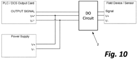
- the DO 2 is connected between an output card of a PLC and a field device (e.g., an actuator such as a solenoid of a field device). While Figs. 9 and 10 shown the DI 1 and the DO 2 as separate elements, these can be integrated into either the PLC or the field device.
- DI 1 shown in Fig. 1 comprises a first controller 10, a first buffer 12, a pull-up resistor 14 and a pull-down resistor 16.
- the first controller 10 is adapted to actuate four MOSFET switches, specifically, a first pull-up switch 18, a first pull-down switch 20, a drive-up switch 22 and a drive-down switch 24.
- the DI 1 also includes three ports, a first positive supply (V+) 25, a first voltage return (V-) 26, and a first signal 27.
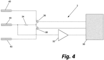
- the DO 2 shown in Fig. 4 comprises a second processor 30, a second buffer 32, and a pull-up/down resistor 34.
- the controller 30 is adapted to actuate two MOSFET switches, specifically, a second pull-up switch 36 and a second pull-down switch 38.
- the DO 2 also contains three ports, specifically, a second positive supply (V+) 40, a second voltage return (V-) 43 and a second signal 44.
- FIGS. 1 and 4 show two separate controllers 10 and 30, other embodiments of the invention may include a single controller combining the functions of controllers 10 and 30. In still other embodiments, the functions performed by controllers 10 and 30 may be performed by a controller of a PLC or a controller of a field device.
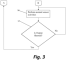
- the controller 10 causes the apparatus to perform a series of steps to ascertain the type of input card of a PLC to which a sensor is connected. These steps are illustrated in Figures 2 and 3 .
- the controller 10 turns both switch 22 and switch 24 off. Switches 22 and 24 are held in their off (non-conducting) state until the type of PLC card wired to signal port 27 is determined. Current is made to flow through resistor 14 by closing switch 18 and opening switch 20, thereby placing a signal to the controller 10 via buffer 12.
- the controller 10 After a predetermined time, the controller 10 performs step 51. More specifically, the buffer 12 reads the voltage and converts it to a logical 1 or 0 which is delivered to the controller 10. The controller 10 determines whether the input level is the same logic as established by the activated pull resistor (i.e., either resistor 14 or resistor 16) and buffer 12. If so, the controller 10 performs step 52. If not, the controller performs step 53.
- the activated pull resistor i.e., either resistor 14 or resistor 16
- step 52 the switches 18 and 20 are actuated to effectively change which pull resistor 14 or 16 is in use, whereby pull-up becomes pull-down and vice versa.
- step 51 is repeated. If the input level at 27 is now different logic than at the activated pull resistor (i.e., either resistor 14 or resistor 16), the controller 10 performs step 53 to identify whether resistor 14 or resistor 16 is then activated. If resistor 14 is activated, the controller 10 knows that the signal port 27 is attached to a sinking/PNP input card of the PLC and the controller 10 performs step 54. If resistor 16 is activated, the controller 10 knows that the signal 27 is attached to a sourcing/NPN card of the PLC and controller 10 performs step 55.
- Both steps 54 and 55 include opening both MOSFET switches 18 and 20 to block current flow through the two resistors 14 and 16.
- Step 54 includes the additional step of enabling the switches 22 and 24 using "active high" logic for the sinking/PNP input card of the PLC attached to the sensor. (In a PNP input card there is a sinking resistor tied to ground.)
- Step 55 includes alternative additional step of using "active low” logic for the sourcing/NPN input card of the PLC attached to the sensor. (In an NPN input card, there is a sourcing resister tied to high.)
- the controller 10 continues by performing normal sensor activity at step 56.
- the controller 10 also performs a test at step 57 to ascertain whether the output of the sensor is shorted. While a user is wiring a device, the user may at first have the device's signal wire connected temporarily (by user error) to the V+ or V- of the power supply, which would make the self-learning algorithm make an incorrect determination. By re-starting the test, it ensures that it will determine the correct card type, even if the user accidently short-circuits the signal wire. So long as no short is detected, the controller 10 continuously performs normal sensor activities. If any short is detected by the controller 10, the controller 10 returns to step 50 and repeats the process including steps 50-56 described above.
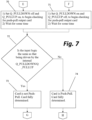
- controller 30 performs the steps illustrated in Figures 5-8 . Specifically, at step 60, resistor 34 is turned on by closing switch 38. In this condition, the signal 44 is sinking current and thus looking for a PNP style output card of a PLC. The controller 30 waits a predetermined time interval before proceeding to step 62.
- step 62 the controller 30 ascertains whether the input level has the same logic as the resistor 34. If so, step 63 is performed such that switches 36 and 38 are actuated to effectively change the direction of the resistor 34 whereby pull-up becomes pull-down and vice versa. After predetermined time interval, step 62 is performed again.
- the controller 30 determines the input level is not the same logic as the resistor 34, the controller performs the test at step 64.
- the controller determines if resistor 34 is then being driven by switch 36 or switch 38.
- the controller 30 next performs step 65 if switch 38 is driving resistor 34 and step 66 if switch 36 is driving resistor 34. More specifically, if switch 38 is driving resistor 34, the PLC's output card is determined to be either a sourcing/PNP output card or a push-pull output card.
- the PLC's output card is either a sinking/NPN output card or a push-pull output card if switch 36 is driving resistor 34.
- step 65 When step 65 is performed, switch 38 is left closed and switch 36 is left open.
- step 66 when step 66 is performed, switch 36 is left closed and switch 38 is left open. In either case, enough current is drawn for the circuit to be compatible with diagnostic type output cards (those which leak current when off, looking for an open circuit) and the controller proceeds to step 67.
- step 67 Normal sensor activities are performed at step 67 and the controller periodically performs step 68 to identify whether there has been a change in the input logic state, indicating it is now the correct time to test for a push-pull type output card. So long as no change in the state of the input logic is detected, the controller continues to perform steps 67 and 68.
- step 69 the controller checks to see if step 65 or step 66 was last performed. If step 65, the controller 30 next performs step 70. If step 66, the controller 30 next performs step 71. Steps 70 and 71 allow the controller to ascertain if the PLC's output card is a push-pull output card.
- step 70 switch 38 is turned off and switch 36 is turned on.
- step 71 switch 38 is turned on and switch 36 is turned off.
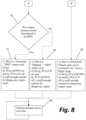
- the controller 30 After performing either step 70 or 71, the controller 30 waits a predetermined time interval and then performs step 72 and again looks to see if the input logic is the same as at the resistor 34. If so, the PLC's output card is determined by the controller 30 at step 73, to not be a push-pull card. Hence, the PLC's output card is either a source/PNP output card or a sinking/NPN card as was previously determined at steps 65 and 66. The controller 30 then performs step 75.
- step 72 determines the input logic not to be the same as the resistor 34
- step 74 the controller 30 identifies the PLC's output card to be a push-pull card. The controller then performs step 76.
- the controller 30 proceeds to step 77 if the controller 30 previously determined that the PLC's output card is a source/PNP card and to step 78 if the PLC's output card was previously determined to be a sinking/NPN card. If the PLC's output card is a sourcing/PNP card, switch 36 is opened and switch 38 is closed at step 77. If a sinking/NPN card was detected, switch 36 is closed and switch 38 is opened at step 78. If the PLC's output card is a push-pull output card, at step 76, the push-pull output card is assumed to be active high logic and the controller 30 closes switch 38 and opens switch 36. This assumption is made given the way most push-pull output cards are fabricated. If this assumption proves to be incorrect, the internal programming of the PLC and/or output card can be reprogrammed so that this assumption is true. After performing the proper step of steps 76, 77 and 78, the controller 30 performs normal control activities at step 80.
- circuits of Figs. 1 and 4 and the program executing the operations reflected in the flow charts of Figs. 2-3 and 5-8 combine to achieve two important results.
- the DI and DO circuits described above may be incorporated into the circuitry of a PLC card. More specifically, one or more DI circuits 1 may be integrated into a PLC output card. This is because the "DI" circuit transmits data to the input of another device such as a field device. The PLC Output card sends data to the input of a field device to control the actuators of the field device. In other cases, the PLC output card just provides power to a field device. Three such DI circuits are incorporated into a PLC output card in the example illustrated in Fig. 12 . These DI circuits are separately coupled to three separate actuators. These actuators may be a part of the same field device or three separate field devices.
- the DO circuitry may be integrated into a PLC input card. This is because the DO circuit receives data from the output of another device enabling the PLC input card to receive data from the output of field devices.
- Fig. 11 illustrates an example in which three DO circuits 2 are integrated into a PLC input card. Each DO circuit 2 is connected to a separate sensor of a field device. These sensors may be part of the same field device or three separate field devices.
- Fig. 13 shows two DI circuits 1 and two DO circuits 2 integrated into a field device having two actuators and two sensors.
- the DI circuits 1 are used to couple the sensors of the field device to the PLC input card(s) of the PLC.
- the D0 circuits 2 are employed to connect the two actuators of the field device to the PLC output card(s) of a PLC.
Landscapes
- Engineering & Computer Science (AREA)
- Physics & Mathematics (AREA)
- Theoretical Computer Science (AREA)
- General Physics & Mathematics (AREA)
- General Engineering & Computer Science (AREA)
- Mathematical Physics (AREA)
- Automation & Control Theory (AREA)
- Computing Systems (AREA)
- Computer Hardware Design (AREA)
- Software Systems (AREA)
- Artificial Intelligence (AREA)
- Medical Informatics (AREA)
- Evolutionary Computation (AREA)
- Data Mining & Analysis (AREA)
- Computer Vision & Pattern Recognition (AREA)
- Programmable Controllers (AREA)
Description
- The present invention relates generally to industrial control of field devices. The present invention relates more specifically to novel devices that are self-learning, able to identify the types of input and output cards used by a programmable logic controller (PLC), and able to adapt the signal paths between a field device and PLC based on the types of input and output card employed by the PLC to ensure the PLC and field device are properly connected.
- A variety of field devices are commonly used in industrial applications. One example of a field device is a valve mechanically coupled to a solenoid which is employed to change the position of the valve, i.e., move the valve to its fully open position, fully closed position or a desired intermediate position between the valve's fully opened and fully closed positions. Such a field device may also include one or more sensors. Such sensors may, for example, be used to determine whether the valve is fully opened or fully closed or the degree to which the valve is open. Such sensors may also be used to determine the amount of flow through the valve.
- Control of the operation of field devices, such as the valve described above, is often provided by a programmable logic controller (PLC). When the PLC is properly connected to the field device, the PLC receives signals from the sensor(s) of the field device. In response to those sensor signals, its internal programming and often inputs received from other sources, the PLC sends control signals to the solenoid to change the position of the valve.
- Of course, proper connection of the field device to the PLC is essential for the PLC to receive signals from the sensors of the field device and for the PLC to deliver control signals to the field device. An improper connection will not only render the field device inoperable but may also cause damage to either the PLC or the field device.
- Three types of input and output cards are typically employed by PLCs. These include NPN, PNP and Push-Pull configurable cards. The actuators (e.g., a solenoid) and sensors employed by field devices each typically include at least three pins to be connected to the PLC. These include a positive supply (V+), a supply return (V-), and a signal. These also are available in three forms, namely, NPN, PNP and Push-Pull configurable. It is necessary for proper connection of a field device to the PLC for the sensor type to match the card type. Likewise, the actuator should match the PLC card type to which it is connected.
- For example, NPN sensors use an NPN or N-channel transistor to "sink" current into the signal pin when active. NPN sensors are adapted to be wired to a sourcing input card of a PLC that have an internal resistor pulled high (typically to 24V). When the sensor is signaling "inactive", the PLC card's pull-up resistor pulls the signal high, which is interpreted as a binary O by the processor of the PLC.
- PNP sensors operate differently. PNP sensors use a PNP or P-channel transistor to "source" current into the signal pin when active. PNP sensors are used with "sinking" input PLC cards that have an internal resistor pulled low to OV. When the sensor is signaling "inactive", the PLC card's pull-down resistor pulls the signal low, which is interpreted by the PLC's processor as a binary O by the processor of the PLC.
- Push-Pull/configurable (PPC) sensors have both an NPN and a PNP style transistor that can be used with both sourcing and sinking style PLC input cards. However, there is inconsistency regarding whether the active state should be "active high" or "active low". The logic of the processor may be adjusted to select either "active high" or an "active low" as the active state.
- In addition to the three pin sensors described above with a single signal pin, some devices include multiple signal pins such that more than three wires are used to connect the pins of the sensors to the PLC. Also, some manufacturers offer two wire (pin) sensors. These sensors can be wired to either NPN or PNP PLC cards, but they are not universally compatible with all PLC cards.
- In addition to the various three wire inputs to the PLC cards discussed above, the outputs from the PLC to the field device vary. For example, two pins may be used to connect a solenoid to the PLC. One pin is always wired to either V+ or V-. the other pin is wired to the PLC's output card. Proper connection requires the user to know if the PLC supplies the V+ or the V- on its signal (output) line. The user will then also know whether to wire the other pin of the field device to V+ or V-. Similar problems exist with two pin solenoids.
- As should be clear from the foregoing, given the variety of PLCs, sensor types and actuator types used in field devices, it is often difficult to properly connect a field device to a PLC. There is a real need for an apparatus that is self-learning and that is able to ascertain and establish a proper connection between the input and output cards of PLCs and a field device.
US 2019/0041452 A1 discloses techniques for increasing a quantity of candidate electronic-component states determinable from one or more input pins. The techniques may use an internal pull resistor to test a strength of an external resistor to gain two extra candidate pin states. Additional candidate electronic-component states that are then gained based on the extra candidate pin states, combinations of pin states of two or more input pins, and/or detecting a short between two or more input pins. -
US7822896B1 discloses a connector apparatus for connection between an I/O module and a device with an interface apparatus for placing signals on contacts of the connector apparatus. -
US 2019/0146543 A1 discloses a bandgap voltage reference in quasi-parallel with a resistor in the input path a digital input circuit. Because of the quasi-parallel nature, the current used by the digital input circuit is limited to an amount based on the value of the external resistor. The input current is split between circuitry used to provide the logic signal across the selected isolation barrier and a sink transistor so that the current remains constant. This allows the digital input circuit to accurately limit input current without needing field-side power. - The foregoing problems are solved by providing circuitry adapted to test, sense and ultimately determine the type of PLC card that is wired to each input and output of a field device. The circuitry resides between the PLC and the field device (or within either the PLC or field device). The circuitry auto-detects the type of PLC card(s). The apparatus does so by determining if the signal(s) are open circuit, short circuit, or have the expected (correct) impedance.
- In its most simple form, the apparatus of the present invention includes at least a circuit referred to herein as a "DI", which is a self-learning input adapted to identify the proper connection of a sensor output of a field device to an input card of a PLC. The apparatus may additionally include a circuit referred to herein as a "DO", which is a self-learning output adapted to identify the proper connection of field device's input to an output card of the PLC. The DI configuration includes a processor, which may be a separate processor, or the same processor employed by either the PLC or the field device. The DI configuration further includes a buffer, a pull-up resistor, a pull-down resistor, a pull-up switch,
a pull-down switch, a drive-up switch and a drive-down switch. Each of the switches may be MOSFET switches adapted to be controlled by the processor. The processor, under program control, operates the switches to ascertain proper connection of a sensor of the field device to the PLC's input card. When the field device includes multiple sensors, duplicates of the DI configuration may be provided, one for each sensor. - The DO configuration also includes a processor which, again, may be a separate processor or the same processor employed by the PLC, the field device or the DI configuration. The DO configuration also includes a second buffer, a second pull-up switch, a second pull-down switch and a pull-up/pull-down resistor. The processor, under program control, operates the switches (which again may be MOSFET switches) to ascertain proper connection of an actuator of the field device to the PLC's output card. If the field device includes multiple actuators, the DO configuration may be duplicated such that there is a separate DO configuration for each actuator.
- For determining types of card used by a programmable logic controller (PLC) for connecting a field device to a PLC, disclosed herein is an apparatus according to
claim 1. - The apparatus may further comprise discrete output circuitry (DO), said DO comprising a second buffer, a pull-up/down resistor, a second pull-up switch, a second pull-down switch, and a second signal port.
- When the DO is attached to a PLC output card, said first controller may be further adapted to control the second pull-up switch and the second pull-down switch of the DO to perform tests enabling the controller to ascertain the type of PLC output card to which the DO is attached.
- The apparatus may further comprise a second controller.
- Said DO may be attached to a PLC output card. Said second controller may be adapted to control the second pull-up switch and the second pull-down switch of the DO to perform tests enabling the second controller to ascertain the type of PLC output card to which the DO is attached.
- Said first controller may also control a field device.
- Said first controller may also control a PLC.
- For determining the types of cards used by a programmable logic controller (PLC) for properly connecting a field device to a PLC, disclosed herein is an apparatus comprising a controller, a connection of a positive voltage supply, a negative voltage return, a discrete input circuit (DI) for determining the type of an input card used by the PLC, and a discrete output circuit (DO) for determining the type of an output card used by the PLC, said DI comprising a first buffer, a pull-up resistor, a pull-down resistor, a first pull-up switch, a first pull-down switch, a series connection of a drive-up switch and a drive-down switch connected between the positive voltage supply and the negative voltage return, and a first signal port connected to a first junction point between the pull-up resistor and the pull-down resistor, a second junction point between the drive-up switch and the drive-down switch and to an input of said first buffer and where said controller is connected in controlling relation to each of the first pull-up switch, first pull-down switch, drive-up switch and drive-down switch, said DO comprising a second buffer, a pull-up/down resistor, a second pull-up switch, a second pull-down switch, and a second signal port, the second signal port being coupled by the pull up/down resistor to a junction point between a series connection of the pull-up switch and the pull-down switch connected between the positive voltage supply and the negative voltage return and where an input to the second buffer is tied to the second signal port, the controller providing control inputs to the second pull-up switch and the second pull-down switch.
- The apparatus may comprise a plurality of DI circuits, each of said DI circuits adapted to be coupled to a separate PLC input card and identify the type of PLC input card to which it is coupled.
- The apparatus may comprise a plurality of DO circuits, each of said DO circuits adapted to be coupled to a separate PLC output card and identify the type of PLC output card to which it is coupled.
- There is disclosed a method for determining a type of input card used by a programmable logic controller (PLC) according to claim 8.
- The step of determining the type of PLC input card to which the DI is attached may comprise the following sub-steps:
- b. closing the first pull-up switch and opening the first pull-down switch so that current flows through the pull-up resistor thereby providing a signal to the controller via the first buffer,
- c. determining whether the input level is the same logic as established by the pull-up resistor and first buffer,
- d. opening the first pull-up switch and closing the first pull-down switch to pass current through the pull-down resistor,
- e. determining whether the input level is the same logic as established by the pull-down resistor and first buffer,
- f. using the determinations made in sub-steps c and e to identify the type of PLC input card to which the DI is attached.
- The method may further comprise the step of performing normal sensor activities until the output is shorted and then repeating sub-steps a through f.
- The method may include the additional steps of connecting a field device to the apparatus and of performing normal sensing and control activities.
- The apparatus may be integrated into a PLC output card.
- The apparatus may be attached to a PLC input card.
- The apparatus may be integrated into a PLC input card.
- The apparatus may be attached to a PLC output card.
- The first controller may also control a field device.
- The first controller may also control a PLC.
- The foregoing features, objects and advantages of the invention will become apparent to those skilled in the art from the following detailed description of the preferred embodiment, especially when considered in conjunction with the accompanying drawings in which like numerals in the several views refer to corresponding parts:
-
Figure 1 is a schematic diagram of the direct input (DI) circuit of an embodiment of the present invention; -
Figures 2-3 together illustrate a flow chart identifying the steps employed by the DI ofFigure 1 to ascertain the proper connection between the input card of a PLC and the output of a sensor; -
Figure 4 is a schematic diagram of the direct output (DO) circuit of an embodiment of the present invention; and -
Figures 5-8 together illustrate a flow chart of the steps employed by the DO ofFigure 4 to ascertain the proper connection between the output card of a PLC and the input of an actuator. -
Figure 9 is a schematic diagram showing the DI ofFigure 1 connected between an input card of a PLC and a field device. -
Figure 10 is a schematic diagram showing the DO ofFigure 4 connected between an output card of a PLC and a field device. -
Figure 11 is a schematic diagram illustrating three DO circuits of the type shown inFigure 4 integrated into a PLC input card with the PLC input card coupled to three different field device sensors which may be part of a single field device or three separate field devices. -
Figure 12 is a schematic diagram illustrating three DI circuits of the type shown inFigure 1 integrated into a PLC output card with the PLC output card coupled to three separate actuators which may be a part of a single field device or three different field devices. -
Figure 13 is a schematic diagram showing a field device into which two DI circuits of the type shown inFigure 1 and two DO circuits of the type shown inFigure 4 are integrated, the DI circuits being employed to couple separate sensors of the field device to a PLC input card, and the DO circuits being employed to couple separate actuators to a PLC output card. - This description of the preferred embodiments is intended to be read in connection with the accompanying drawings, which are to be considered part of the entire written description of this invention. In the description, relative terms such as "lower", "upper", "horizontal", "vertical", "above", "below", "up", "down", "top" and "bottom" as well as derivatives thereof (e.g., "horizontally", "downwardly", "upwardly", etc.) should be construed to refer to the orientation as then described or as shown in the drawings under discussion. These relative terms are for convenience of description and do not require that the apparatus be constructed or operated in a particular orientation. Terms such as "connected", "connecting", "attached", "attaching", "join" and "joining" are used interchangeably and refer to one structure or surface being secured to another structure or surface or integrally fabricated in one piece, unless expressively described otherwise.
- The apparatus of the present invention, in its simplest form, includes at least a discrete input circuit (DI) 1 such as that shown in
Fig. 1 and optionally a discrete output circuit (DO) 2 such as that shown inFig. 4 . In other forms, the apparatus includes both aDI circuit 1 and aDO circuit 2. In still other forms, the apparatus includesmultiple DI circuits 1, or at least a DI and multiple DO circuits, or even multiple DI circuits andmultiple DO circuits 2. See, e.g.,Figs. 11-13 . - As shown in
Fig. 9 , theDI 1 is connected between an input card of a PLC and a field device (and most typically a sensor of a field device). As shown inFig. 10 , theDO 2 is connected between an output card of a PLC and a field device (e.g., an actuator such as a solenoid of a field device). WhileFigs. 9 and10 shown theDI 1 and theDO 2 as separate elements, these can be integrated into either the PLC or the field device. -
DI 1 shown inFig. 1 comprises afirst controller 10, afirst buffer 12, a pull-upresistor 14 and a pull-down resistor 16. Thefirst controller 10 is adapted to actuate four MOSFET switches, specifically, a first pull-up switch 18, a first pull-down switch 20, a drive-up switch 22 and a drive-down switch 24. TheDI 1 also includes three ports, a first positive supply (V+) 25, a first voltage return (V-) 26, and afirst signal 27. - The
DO 2 shown inFig. 4 comprises asecond processor 30, a second buffer 32, and a pull-up/downresistor 34. Thecontroller 30 is adapted to actuate two MOSFET switches, specifically, a second pull-up switch 36 and a second pull-down switch 38. TheDO 2 also contains three ports, specifically, a second positive supply (V+) 40, a second voltage return (V-) 43 and asecond signal 44. - While
Figures 1 and4 show twoseparate controllers controllers controllers - In the embodiment shown in the drawings, the
controller 10 causes the apparatus to perform a series of steps to ascertain the type of input card of a PLC to which a sensor is connected. These steps are illustrated inFigures 2 and3 . - At
step 50, thecontroller 10 turns both switch 22 and switch 24 off.Switches port 27 is determined. Current is made to flow throughresistor 14 by closingswitch 18 andopening switch 20, thereby placing a signal to thecontroller 10 viabuffer 12. - After a predetermined time, the
controller 10 performsstep 51. More specifically, thebuffer 12 reads the voltage and converts it to a logical 1 or 0 which is delivered to thecontroller 10. Thecontroller 10 determines whether the input level is the same logic as established by the activated pull resistor (i.e., eitherresistor 14 or resistor 16) andbuffer 12. If so, thecontroller 10 performsstep 52. If not, the controller performsstep 53. - At
step 52, theswitches resistor step 51 is repeated. If the input level at 27 is now different logic than at the activated pull resistor (i.e., eitherresistor 14 or resistor 16), thecontroller 10 performsstep 53 to identify whetherresistor 14 orresistor 16 is then activated. Ifresistor 14 is activated, thecontroller 10 knows that thesignal port 27 is attached to a sinking/PNP input card of the PLC and thecontroller 10 performsstep 54. Ifresistor 16 is activated, thecontroller 10 knows that thesignal 27 is attached to a sourcing/NPN card of the PLC andcontroller 10 performsstep 55. - Both
steps resistors Step 54 includes the additional step of enabling theswitches Step 55 includes alternative additional step of using "active low" logic for the sourcing/NPN input card of the PLC attached to the sensor. (In an NPN input card, there is a sourcing resister tied to high.) - After either step 54 or 55 has been performed, the
controller 10 continues by performing normal sensor activity atstep 56. Thecontroller 10 also performs a test atstep 57 to ascertain whether the output of the sensor is shorted. While a user is wiring a device, the user may at first have the device's signal wire connected temporarily (by user error) to the V+ or V- of the power supply, which would make the self-learning algorithm make an incorrect determination. By re-starting the test, it ensures that it will determine the correct card type, even if the user accidently short-circuits the signal wire. So long as no short is detected, thecontroller 10 continuously performs normal sensor activities. If any short is detected by thecontroller 10, thecontroller 10 returns to step 50 and repeats the process including steps 50-56 described above. - Further, the
controller 30 performs the steps illustrated inFigures 5-8 . Specifically, atstep 60,resistor 34 is turned on by closingswitch 38. In this condition, thesignal 44 is sinking current and thus looking for a PNP style output card of a PLC. Thecontroller 30 waits a predetermined time interval before proceeding to step 62. - At
step 62, thecontroller 30 ascertains whether the input level has the same logic as theresistor 34. If so, step 63 is performed such thatswitches resistor 34 whereby pull-up becomes pull-down and vice versa. After predetermined time interval,step 62 is performed again. - When at
step 62 thecontroller 30 determines the input level is not the same logic as theresistor 34, the controller performs the test atstep 64. Atstep 64, the controller determines ifresistor 34 is then being driven byswitch 36 orswitch 38. Thecontroller 30 next performsstep 65 ifswitch 38 is drivingresistor 34 and step 66 ifswitch 36 is drivingresistor 34. More specifically, ifswitch 38 is drivingresistor 34, the PLC's output card is determined to be either a sourcing/PNP output card or a push-pull output card. The PLC's output card is either a sinking/NPN output card or a push-pull output card ifswitch 36 is drivingresistor 34. - When
step 65 is performed,switch 38 is left closed and switch 36 is left open. Alternatively, whenstep 66 is performed,switch 36 is left closed and switch 38 is left open. In either case, enough current is drawn for the circuit to be compatible with diagnostic type output cards (those which leak current when off, looking for an open circuit) and the controller proceeds to step 67. - Normal sensor activities are performed at
step 67 and the controller periodically performsstep 68 to identify whether there has been a change in the input logic state, indicating it is now the correct time to test for a push-pull type output card. So long as no change in the state of the input logic is detected, the controller continues to performsteps - As soon as a change in the input logic state is detected, the controller performs
step 69. Here, the controller checks to see ifstep 65 orstep 66 was last performed. Ifstep 65, thecontroller 30 next performsstep 70. Ifstep 66, thecontroller 30 next performsstep 71.Steps step 70,switch 38 is turned off and switch 36 is turned on. Alternatively, whenstep 71 is performed,switch 38 is turned on and switch 36 is turned off. - After performing either step 70 or 71, the
controller 30 waits a predetermined time interval and then performsstep 72 and again looks to see if the input logic is the same as at theresistor 34. If so, the PLC's output card is determined by thecontroller 30 atstep 73, to not be a push-pull card. Hence, the PLC's output card is either a source/PNP output card or a sinking/NPN card as was previously determined atsteps controller 30 then performsstep 75. - Alternatively, if at
step 72 thecontroller 30 determines the input logic not to be the same as theresistor 34, atstep 74 thecontroller 30 identifies the PLC's output card to be a push-pull card. The controller then performsstep 76. - At
step 75, thecontroller 30 proceeds to step 77 if thecontroller 30 previously determined that the PLC's output card is a source/PNP card and to step 78 if the PLC's output card was previously determined to be a sinking/NPN card. If the PLC's output card is a sourcing/PNP card, switch 36 is opened and switch 38 is closed atstep 77. If a sinking/NPN card was detected, switch 36 is closed and switch 38 is opened atstep 78. If the PLC's output card is a push-pull output card, atstep 76, the push-pull output card is assumed to be active high logic and thecontroller 30 closes switch 38 and opensswitch 36. This assumption is made given the way most push-pull output cards are fabricated. If this assumption proves to be incorrect, the internal programming of the PLC and/or output card can be reprogrammed so that this assumption is true. After performing the proper step ofsteps controller 30 performs normal control activities atstep 80. - One skilled in the art will appreciate from the forgoing that the circuits of
Figs. 1 and4 and the program executing the operations reflected in the flow charts ofFigs. 2-3 and5-8 combine to achieve two important results. First, the types of input and output card of the PLC to which the field device is attached are identified. Second, proper connections are established between those input and output cards and the field device. - One skilled in the art will further appreciate that modifications may be made without deviating from the invention. For example, the DI and DO circuits described above may be incorporated into the circuitry of a PLC card. More specifically, one or
more DI circuits 1 may be integrated into a PLC output card. This is because the "DI" circuit transmits data to the input of another device such as a field device. The PLC Output card sends data to the input of a field device to control the actuators of the field device. In other cases, the PLC output card just provides power to a field device. Three such DI circuits are incorporated into a PLC output card in the example illustrated inFig. 12 . These DI circuits are separately coupled to three separate actuators. These actuators may be a part of the same field device or three separate field devices. - Likewise, the DO circuitry may be integrated into a PLC input card. This is because the DO circuit receives data from the output of another device enabling the PLC input card to receive data from the output of field devices.
Fig. 11 illustrates an example in which three DOcircuits 2 are integrated into a PLC input card. EachDO circuit 2 is connected to a separate sensor of a field device. These sensors may be part of the same field device or three separate field devices. -
Fig. 13 shows twoDI circuits 1 and twoDO circuits 2 integrated into a field device having two actuators and two sensors. TheDI circuits 1 are used to couple the sensors of the field device to the PLC input card(s) of the PLC. TheD0 circuits 2 are employed to connect the two actuators of the field device to the PLC output card(s) of a PLC. - This invention has been described herein in considerable detail in order to comply with the patent statutes and to provide those skilled in the art with the information needed to apply the novel principles and to construct and use embodiments of the example as required. However, it is to be understood that the invention can be carried out by specifically different devices and that various modifications can be accomplished without departing from the scope of the invention itself.
Claims (12)
- An apparatus for determining a type of card used by a programmable logic controller (PLC), the card configured to connect an output of a sensor of a field device to the PLC, the apparatus comprising:a first controller (10),at least one positive voltage supply (25),at least one negative voltage return (26), anddiscrete input circuitry, DI, (1) for determining the type of an input card used by the PLC,said DI comprising:a first buffer (12),a pull-up resistor (14),a pull-down resistor (16),a first pull-up switch (18),a first pull-down switch (20),a series connection of a drive-up switch (22) and a drive-down switch (24) connected between the positive voltage supply and the negative voltage return,a first signal port (27) connected to a first junction point between the pull-up resistor and the pull-down resistor, a second junction point between the drive-up switch and the drive-down switch and to an input of said first bufferwhere said controller is connected in controlling relation to each of the first pull-up switch, first pull-down switch, drive-up switch and drive-down switch, wherein said first controller is configured to:(a) determine whether the output of the sensor is shorted (57),(b) perform normal sensor activity if the output of the sensor is not shorted (56), and(c) if the output of the sensor is shorted or upon apparatus initialization(i) turn off both the drive-up switch (22) and the drive-down switch (24) (50);(ii) actuate the first pull-up switch (18) and the pull-down switch (20) to selectively activate one of the pull-up resistor (14) or the pull-down resistor (16) to provide a pull influence signal to the controller (10) via buffer (12) (50-52);(iii) after a predetermined time compare an input level at the first signal port (27) to the pull influence signal (51),(iv) when the input level and the pull influence signal are the same, actuate the first pull-up switch (18) or the pull-down switch (20) to selectively activate the other of the pull-up resistor (14) or the pull-down resistor (16) to provide a pull influence signal to the controller (10) via buffer (12) and wait a predetermined interval (52),(v) continue with additional sub-step (iv) until the input level is different than the pull influence signal (51-52),(vi) when the input level is different from the pull influence signal determine whether the card is a sinking/PNP card which will be the case if the pull-up resistor (14) is active or a sourcing/NPN card which will be the case if the pull-down resistor (16) is active (53-55),(vii) opening both the first pull-up switch and the first pull-down switch to block current flow through the pull-up resistor and the pull-down resistor, and if the card is determined as a sinking/PNP card, enable the drive-up switch and the drive-down switch using "active high" logic, or if the card is determined as a sourcing/NPN card, enable the drive-up switch and the drive-down switch using "active low" logic.
- The apparatus of claim 1 wherein said first controller is adapted to control the first pull-up switch, the first pull-down switch, the drive-up switch, and the drive-down switch of the DI when the DI is attached to a PLC input card, to perform tests enabling the first controller to ascertain the type of PLC input card to which the DI is attached.
- The apparatus of claim 1 wherein the apparatus further comprises discrete output circuitry, DO, for determining the type of an output card used by the PLC, said DO comprising:a second buffer,a pull-up/down resistor,a second pull-up switch,a second pull-down switch, anda second signal port,the second signal port being coupled by the pull up/down resistor to a junction point between a series connection of the pull-up switch and the pull-down switch connectable between the positive voltage supply and the negative voltage return andwhere an input to the second buffer is tied to the second signal port, the controller providing control inputs to the second pull-up switch and the second pull-down switch.
- The apparatus of claim 3 wherein said first controller is further adapted to control the second pull-up switch and the second pull-down switch of the DO when the DO is attached to a PLC output card, to perform tests enabling the controller to ascertain the type of PLC output card to which the DO is attached; or
the apparatus of claim 2 wherein said first controller is adapted to control the pull-up switch and the pull-down switch of the DO when the DO is attached to a PLC output card, to perform tests enabling the controller to ascertain the type of PLC output card to which the DO is attached. - The apparatus of claim 3 further comprising a second controller, and wherein said second controller is adapted to control the second pull-up switch and the second pull-down switch of the DO when said DO is attached to a PLC output card, to perform tests enabling the second controller to ascertain the type of PLC output card to which the DO is attached, in particular adapted to:(i) determine an input level at the signal port (44), enable the pull-up/down resistor (34) by closing the pull-down switch (38) to provide a pull influence input signal, wait a predetermined period of time and ascertain whether the input level is the same as a pull-up/down influence signal (60-62);(ii) if the input level is the same as the pull-up/down influence signal, actuate the pull-up switch (36) and the pull-down switch (38) to change the direction of pull-up/down resistor (34) and after a predetermined period of time (63) ascertain whether the input level is the same as the pull-up/down influence signal;(iii) continue with additional sub-step (ii) until the input level is different than the pull-up/down influence (62-63);(iv) whenever the input level is not the same as the pull-up/down influence signal, determine whether the pull-up/down resistor (34) is being driven by the pull-up switch (36), in which case the card is either a sinking/NPN output card or a push-pull output card in an NPN configuration, or driven by the pull-down switch (38), in which case the card is either a sourcing/PNP card or a push-pull output card in a PNP configuration (64-66);(v) perform normal field device activity while monitoring the input signal for a change in the input level (67);(vi) when a change in the input level is detected and the pull-up/down resistor (34) is being driven by the pull-up switch (36), set the pull-up switch (36) to off and the pull-down switch (38) to on, and when a change in the input level is detected and the pull-up/down resistor (34) is being driven by the pull-down switch (38), set the pull-up switch (36) to on and the pull-down switch (38) to off (68-71),(vii) after a predetermined time determine whether the input level is the same as the pull-up/down influence signal in which case the card is not a push-pull card or different than the pull-up/down influence signal in which case the card is a push-pull card (72-74);(viii) selectively configure the pull-up switch (36) and the pull-down switch (38) such that pull-up/down resistor (34) is compatible with the detected card type (75-78);(ix) and perform normal field device activity (80).
- The apparatus of claim 1 wherein said first controller is also configured to control a field device or a PLC.
- The apparatus of claim 1 wherein apparatus comprises a plurality of DI circuits, each of said DI circuits adapted to be coupled to a separate PLC input card and identify the type of PLC input card to which it is coupled.
- A method for determining a type of input card used by a programmable logic controller (PLC) to connect a field device to the PLC, the method comprising:a. providing an apparatus of claim 1;b. attaching the DI to a PLC input card,c. determining the type of PLC input card to which the DI is attached by
(0) turning the drive-up switch and the drive-down switch off until the type of PLC input card is determined,(i) actuating the first pull-up switch 18 and the pull-down switch (20) to selectively activate one of the pull-up resistor (14) and the pull-down resistor (16) to provide a first influence signal to the controller (10) via the buffer (12) (50-52);(ii) after a predetermined time comparing an input level at the first signal port (27) to the first influence signal (51),(iii) when the input level and the first influence signal are the same, actuate the pull-up switch (18) and pull-down switch (20) to selectively activate the other of the pull-up resistor (14) and the pull-down resistor (16) to provide a second influence signal to the controller (10) via the buffer (12) (50-52) and wait a predetermined interval,(iv) when the input level and the second influence signal are different, determine whether the card is a sinking/PNP card which will be the case if the pull-up resistor (14) is active or a sourcing/NPN card which will be the case if the pull-down resistor (16) is active (53-55). - The method of claim 8 wherein the step of determining the type of PLC input card to which the DI is attached comprises the following sub-steps:b. closing the first pull-up switch and opening the first pull-down switch so that current flows through the pull-up resistor thereby providing a signal in a logic state to the controller via the first buffer,c. determining whether an input level is in the same logic state as established by the pull-up resistor and first buffer,d. opening the first pull-up switch and closing the first pull-down switch to pass current through the pull-down resistor,e. determining whether the input level is the same logic state as established by the pull-down resistor and first buffer,f. using the determinations made in sub-steps c and e to identify the type of PLC input card to which the DI is attached.
- The method of claim 9 further comprising the step of performing normal sensor activities until the output is shorted and then repeating sub-steps a through f.
- The method of claim 8 including the additional steps of connecting a field device to the apparatus and of performing normal sensing and control activities.
- A system comprising the apparatus of claim 1 wherein said apparatus is: integrated into a PLC output card; or attached to a PLC input card.
Applications Claiming Priority (1)
| Application Number | Priority Date | Filing Date | Title |
|---|---|---|---|
| US16/747,238 US11138137B2 (en) | 2020-01-20 | 2020-01-20 | Self-learning apparatus for connecting inputs and outputs of a programmable logic controller to a field device |
Publications (2)
| Publication Number | Publication Date |
|---|---|
| EP3851926A1 EP3851926A1 (en) | 2021-07-21 |
| EP3851926B1 true EP3851926B1 (en) | 2024-12-18 |
Family
ID=72885391
Family Applications (1)
| Application Number | Title | Priority Date | Filing Date |
|---|---|---|---|
| EP20201733.1A Active EP3851926B1 (en) | 2020-01-20 | 2020-10-14 | Self-learning apparatus for connecting inputs and outputs of a programmable logic controller to a field device |
Country Status (4)
| Country | Link |
|---|---|
| US (1) | US11138137B2 (en) |
| EP (1) | EP3851926B1 (en) |
| CN (1) | CN113138583B (en) |
| FI (1) | FI3851926T3 (en) |
Families Citing this family (2)
| Publication number | Priority date | Publication date | Assignee | Title |
|---|---|---|---|---|
| LU101865B1 (en) * | 2020-06-17 | 2021-12-17 | Phoenix Contact Gmbh & Co | Technology for processing and exchanging signals between field device and controller |
| WO2024178701A1 (en) * | 2023-03-02 | 2024-09-06 | Honeywell International Inc. | Actuator controller with control signal loss protection |
Family Cites Families (15)
| Publication number | Priority date | Publication date | Assignee | Title |
|---|---|---|---|---|
| US6574743B1 (en) * | 1999-03-30 | 2003-06-03 | Siemens Energy & Automation | Programmable logic controller method, system and apparatus |
| US7024248B2 (en) * | 2000-10-16 | 2006-04-04 | Remon Medical Technologies Ltd | Systems and methods for communicating with implantable devices |
| US7822896B1 (en) | 2001-02-14 | 2010-10-26 | Berkeley Process Control, Inc. | Electronically configurable connector module |
| JP3966873B2 (en) * | 2003-10-08 | 2007-08-29 | 株式会社東芝 | Logic circuit device and operating voltage changing method |
| US7142132B2 (en) * | 2004-11-09 | 2006-11-28 | General Motors Corporation | Methods and systems for multi-state switching using at least one ternary input and at least one discrete input |
| US7756812B2 (en) * | 2005-09-22 | 2010-07-13 | Eastman Kodak Company | Adaptive input-cell circuitry useful in configurable electronic controllers |
| US7509445B2 (en) * | 2006-04-12 | 2009-03-24 | National Instruments Corporation | Adapting a plurality of measurement cartridges using cartridge controllers |
| US8688955B2 (en) * | 2010-08-13 | 2014-04-01 | Micron Technology, Inc. | Line termination methods and apparatus |
| US9483039B2 (en) * | 2012-04-19 | 2016-11-01 | Rosemount Inc. | Wireless field device having discrete input/output |
| KR20160005942A (en) * | 2014-07-08 | 2016-01-18 | 에스케이하이닉스 주식회사 | Inverter and electronic device with the same |
| CN205002234U (en) * | 2015-07-29 | 2016-01-27 | 北京天泰瑞祥科技发展有限公司 | High accuracy air purifier |
| US10003192B2 (en) * | 2015-09-28 | 2018-06-19 | Nxp B.V. | Bus interfaces with unpowered termination |
| CN206096883U (en) * | 2016-07-29 | 2017-04-12 | 西门子(中国)有限公司 | Programmable logic controler and have its controlgear |
| US10234497B2 (en) | 2017-08-07 | 2019-03-19 | Google Llc | Electronic component state determination |
| US10281946B1 (en) | 2017-11-10 | 2019-05-07 | Texas Instruments Incorporated | Input current limit in digital input receivers |
-
2020
- 2020-01-20 US US16/747,238 patent/US11138137B2/en active Active
- 2020-10-14 FI FIEP20201733.1T patent/FI3851926T3/en active
- 2020-10-14 EP EP20201733.1A patent/EP3851926B1/en active Active
-
2021
- 2021-01-20 CN CN202110076055.0A patent/CN113138583B/en active Active
Also Published As
| Publication number | Publication date |
|---|---|
| FI3851926T3 (en) | 2025-01-21 |
| US20210224207A1 (en) | 2021-07-22 |
| CN113138583B (en) | 2024-08-23 |
| CN113138583A (en) | 2021-07-20 |
| US11138137B2 (en) | 2021-10-05 |
| EP3851926A1 (en) | 2021-07-21 |
Similar Documents
| Publication | Publication Date | Title |
|---|---|---|
| US7609087B1 (en) | Integrated circuit device programming with partial power | |
| US7254452B2 (en) | Distributed input/output control systems and methods | |
| US8656065B1 (en) | Method and apparatus for automatically selecting a plurality of modes for programmable interface circuit by coupling field devices to process controllers | |
| EP2546984B1 (en) | Sensor with concurrent autosensing of output mode and manual selection | |
| EP3851926A1 (en) | Self-learning apparatus for connecting inputs and outputs of a programmable logic controller to a field device | |
| EP0743529A1 (en) | Method and corresponding circuit for detecting an openload | |
| EP0163845B1 (en) | Diagnostic protection circuit and method | |
| WO2018208750A1 (en) | Wire break detection in digital input receivers | |
| US10006557B2 (en) | Valve manifold circuit board with serial communication and control circuit line | |
| KR102099355B1 (en) | Integrated circuit test apparatus | |
| US10379144B2 (en) | Arrangement having two redundant modules | |
| US9856985B2 (en) | Valve manifold circuit board with serial communication circuit line | |
| US8102285B2 (en) | Modular debouncing device | |
| CN101268426A (en) | Adaptive input cell circuit | |
| CN110622015A (en) | Device for supplying power to a controller and method for monitoring the power supply | |
| CN107024237B (en) | Device with at least two peripheral units and one sensor | |
| TW477054B (en) | Semiconductor device having identifying circuit and method of identifying function | |
| US8384512B2 (en) | Detection sensor and setting information acquisition method thereof | |
| US6292409B1 (en) | System for programmable chip initialization | |
| GB2531580B (en) | Improvements in building management systems | |
| CN103718565B (en) | switch module | |
| US20090038185A1 (en) | Valve Switch Unit | |
| CN110069026B (en) | Adaptive IO monitor | |
| US10649038B2 (en) | Output module, control system and method for testing an output module connected to a complex load | |
| JP4036181B2 (en) | Gas shut-off device |
Legal Events
| Date | Code | Title | Description |
|---|---|---|---|
| PUAI | Public reference made under article 153(3) epc to a published international application that has entered the european phase |
Free format text: ORIGINAL CODE: 0009012 |
|
| STAA | Information on the status of an ep patent application or granted ep patent |
Free format text: STATUS: THE APPLICATION HAS BEEN PUBLISHED |
|
| AK | Designated contracting states |
Kind code of ref document: A1 Designated state(s): AL AT BE BG CH CY CZ DE DK EE ES FI FR GB GR HR HU IE IS IT LI LT LU LV MC MK MT NL NO PL PT RO RS SE SI SK SM TR |
|
| STAA | Information on the status of an ep patent application or granted ep patent |
Free format text: STATUS: REQUEST FOR EXAMINATION WAS MADE |
|
| 17P | Request for examination filed |
Effective date: 20210903 |
|
| RBV | Designated contracting states (corrected) |
Designated state(s): AL AT BE BG CH CY CZ DE DK EE ES FI FR GB GR HR HU IE IS IT LI LT LU LV MC MK MT NL NO PL PT RO RS SE SI SK SM TR |
|
| STAA | Information on the status of an ep patent application or granted ep patent |
Free format text: STATUS: EXAMINATION IS IN PROGRESS |
|
| 17Q | First examination report despatched |
Effective date: 20220922 |
|
| GRAP | Despatch of communication of intention to grant a patent |
Free format text: ORIGINAL CODE: EPIDOSNIGR1 |
|
| STAA | Information on the status of an ep patent application or granted ep patent |
Free format text: STATUS: GRANT OF PATENT IS INTENDED |
|
| RAP3 | Party data changed (applicant data changed or rights of an application transferred) |
Owner name: VALMET FLOW CONTROL INC. |
|
| INTG | Intention to grant announced |
Effective date: 20240910 |
|
| GRAS | Grant fee paid |
Free format text: ORIGINAL CODE: EPIDOSNIGR3 |
|
| GRAA | (expected) grant |
Free format text: ORIGINAL CODE: 0009210 |
|
| STAA | Information on the status of an ep patent application or granted ep patent |
Free format text: STATUS: THE PATENT HAS BEEN GRANTED |
|
| P01 | Opt-out of the competence of the unified patent court (upc) registered |
Free format text: CASE NUMBER: APP_58770/2024 Effective date: 20241028 |
|
| AK | Designated contracting states |
Kind code of ref document: B1 Designated state(s): AL AT BE BG CH CY CZ DE DK EE ES FI FR GB GR HR HU IE IS IT LI LT LU LV MC MK MT NL NO PL PT RO RS SE SI SK SM TR |
|
| REG | Reference to a national code |
Ref country code: CH Ref legal event code: EP |
|
| REG | Reference to a national code |
Ref country code: DE Ref legal event code: R096 Ref document number: 602020043265 Country of ref document: DE |
|
| REG | Reference to a national code |
Ref country code: IE Ref legal event code: FG4D |
|
| REG | Reference to a national code |
Ref country code: FI Ref legal event code: FGE |
|
| REG | Reference to a national code |
Ref country code: LT Ref legal event code: MG9D |
|
| PG25 | Lapsed in a contracting state [announced via postgrant information from national office to epo] |
Ref country code: HR Free format text: LAPSE BECAUSE OF FAILURE TO SUBMIT A TRANSLATION OF THE DESCRIPTION OR TO PAY THE FEE WITHIN THE PRESCRIBED TIME-LIMIT Effective date: 20241218 |
|
| PG25 | Lapsed in a contracting state [announced via postgrant information from national office to epo] |
Ref country code: BG Free format text: LAPSE BECAUSE OF FAILURE TO SUBMIT A TRANSLATION OF THE DESCRIPTION OR TO PAY THE FEE WITHIN THE PRESCRIBED TIME-LIMIT Effective date: 20241218 |
|
| PG25 | Lapsed in a contracting state [announced via postgrant information from national office to epo] |
Ref country code: NO Free format text: LAPSE BECAUSE OF FAILURE TO SUBMIT A TRANSLATION OF THE DESCRIPTION OR TO PAY THE FEE WITHIN THE PRESCRIBED TIME-LIMIT Effective date: 20250318 |
|
| REG | Reference to a national code |
Ref country code: NL Ref legal event code: MP Effective date: 20241218 |
|
| PG25 | Lapsed in a contracting state [announced via postgrant information from national office to epo] |
Ref country code: LV Free format text: LAPSE BECAUSE OF FAILURE TO SUBMIT A TRANSLATION OF THE DESCRIPTION OR TO PAY THE FEE WITHIN THE PRESCRIBED TIME-LIMIT Effective date: 20241218 Ref country code: GR Free format text: LAPSE BECAUSE OF FAILURE TO SUBMIT A TRANSLATION OF THE DESCRIPTION OR TO PAY THE FEE WITHIN THE PRESCRIBED TIME-LIMIT Effective date: 20250319 |
|
| PG25 | Lapsed in a contracting state [announced via postgrant information from national office to epo] |
Ref country code: RS Free format text: LAPSE BECAUSE OF FAILURE TO SUBMIT A TRANSLATION OF THE DESCRIPTION OR TO PAY THE FEE WITHIN THE PRESCRIBED TIME-LIMIT Effective date: 20250318 |
|
| PG25 | Lapsed in a contracting state [announced via postgrant information from national office to epo] |
Ref country code: NL Free format text: LAPSE BECAUSE OF FAILURE TO SUBMIT A TRANSLATION OF THE DESCRIPTION OR TO PAY THE FEE WITHIN THE PRESCRIBED TIME-LIMIT Effective date: 20241218 |
|
| REG | Reference to a national code |
Ref country code: AT Ref legal event code: MK05 Ref document number: 1752737 Country of ref document: AT Kind code of ref document: T Effective date: 20241218 |
|
| PG25 | Lapsed in a contracting state [announced via postgrant information from national office to epo] |
Ref country code: SM Free format text: LAPSE BECAUSE OF FAILURE TO SUBMIT A TRANSLATION OF THE DESCRIPTION OR TO PAY THE FEE WITHIN THE PRESCRIBED TIME-LIMIT Effective date: 20241218 |
|
| PG25 | Lapsed in a contracting state [announced via postgrant information from national office to epo] |
Ref country code: PL Free format text: LAPSE BECAUSE OF FAILURE TO SUBMIT A TRANSLATION OF THE DESCRIPTION OR TO PAY THE FEE WITHIN THE PRESCRIBED TIME-LIMIT Effective date: 20241218 |
|
| PG25 | Lapsed in a contracting state [announced via postgrant information from national office to epo] |
Ref country code: ES Free format text: LAPSE BECAUSE OF FAILURE TO SUBMIT A TRANSLATION OF THE DESCRIPTION OR TO PAY THE FEE WITHIN THE PRESCRIBED TIME-LIMIT Effective date: 20241218 |
|
| PG25 | Lapsed in a contracting state [announced via postgrant information from national office to epo] |
Ref country code: IS Free format text: LAPSE BECAUSE OF FAILURE TO SUBMIT A TRANSLATION OF THE DESCRIPTION OR TO PAY THE FEE WITHIN THE PRESCRIBED TIME-LIMIT Effective date: 20250418 |
|
| PG25 | Lapsed in a contracting state [announced via postgrant information from national office to epo] |
Ref country code: PT Free format text: LAPSE BECAUSE OF FAILURE TO SUBMIT A TRANSLATION OF THE DESCRIPTION OR TO PAY THE FEE WITHIN THE PRESCRIBED TIME-LIMIT Effective date: 20250421 |
|
| PG25 | Lapsed in a contracting state [announced via postgrant information from national office to epo] |
Ref country code: EE Free format text: LAPSE BECAUSE OF FAILURE TO SUBMIT A TRANSLATION OF THE DESCRIPTION OR TO PAY THE FEE WITHIN THE PRESCRIBED TIME-LIMIT Effective date: 20241218 |
|
| PG25 | Lapsed in a contracting state [announced via postgrant information from national office to epo] |
Ref country code: AT Free format text: LAPSE BECAUSE OF FAILURE TO SUBMIT A TRANSLATION OF THE DESCRIPTION OR TO PAY THE FEE WITHIN THE PRESCRIBED TIME-LIMIT Effective date: 20241218 Ref country code: RO Free format text: LAPSE BECAUSE OF FAILURE TO SUBMIT A TRANSLATION OF THE DESCRIPTION OR TO PAY THE FEE WITHIN THE PRESCRIBED TIME-LIMIT Effective date: 20241218 |
|
| PG25 | Lapsed in a contracting state [announced via postgrant information from national office to epo] |
Ref country code: SK Free format text: LAPSE BECAUSE OF FAILURE TO SUBMIT A TRANSLATION OF THE DESCRIPTION OR TO PAY THE FEE WITHIN THE PRESCRIBED TIME-LIMIT Effective date: 20241218 |
|
| PG25 | Lapsed in a contracting state [announced via postgrant information from national office to epo] |
Ref country code: CZ Free format text: LAPSE BECAUSE OF FAILURE TO SUBMIT A TRANSLATION OF THE DESCRIPTION OR TO PAY THE FEE WITHIN THE PRESCRIBED TIME-LIMIT Effective date: 20241218 |
|
| PG25 | Lapsed in a contracting state [announced via postgrant information from national office to epo] |
Ref country code: SE Free format text: LAPSE BECAUSE OF FAILURE TO SUBMIT A TRANSLATION OF THE DESCRIPTION OR TO PAY THE FEE WITHIN THE PRESCRIBED TIME-LIMIT Effective date: 20241218 |
|
| REG | Reference to a national code |
Ref country code: DE Ref legal event code: R097 Ref document number: 602020043265 Country of ref document: DE |
|
| PG25 | Lapsed in a contracting state [announced via postgrant information from national office to epo] |
Ref country code: DK Free format text: LAPSE BECAUSE OF FAILURE TO SUBMIT A TRANSLATION OF THE DESCRIPTION OR TO PAY THE FEE WITHIN THE PRESCRIBED TIME-LIMIT Effective date: 20241218 |
|
| PLBE | No opposition filed within time limit |
Free format text: ORIGINAL CODE: 0009261 |
|
| STAA | Information on the status of an ep patent application or granted ep patent |
Free format text: STATUS: NO OPPOSITION FILED WITHIN TIME LIMIT |
|
| 26N | No opposition filed |
Effective date: 20250919 |
|
| PGFP | Annual fee paid to national office [announced via postgrant information from national office to epo] |
Ref country code: DE Payment date: 20251021 Year of fee payment: 6 |
|
| PGFP | Annual fee paid to national office [announced via postgrant information from national office to epo] |
Ref country code: GB Payment date: 20251022 Year of fee payment: 6 |
|
| PGFP | Annual fee paid to national office [announced via postgrant information from national office to epo] |
Ref country code: FI Payment date: 20251028 Year of fee payment: 6 Ref country code: IT Payment date: 20251024 Year of fee payment: 6 |
|
| PGFP | Annual fee paid to national office [announced via postgrant information from national office to epo] |
Ref country code: FR Payment date: 20251030 Year of fee payment: 6 |
|
| PGFP | Annual fee paid to national office [announced via postgrant information from national office to epo] |
Ref country code: IE Payment date: 20251024 Year of fee payment: 6 |