EP3851874A1 - Method and device for acquiring augmented reality or virtual reality information - Google Patents
Method and device for acquiring augmented reality or virtual reality information Download PDFInfo
- Publication number
- EP3851874A1 EP3851874A1 EP20176137.6A EP20176137A EP3851874A1 EP 3851874 A1 EP3851874 A1 EP 3851874A1 EP 20176137 A EP20176137 A EP 20176137A EP 3851874 A1 EP3851874 A1 EP 3851874A1
- Authority
- EP
- European Patent Office
- Prior art keywords
- information
- collected object
- collected
- mobile terminal
- spatial structure
- Prior art date
- Legal status (The legal status is an assumption and is not a legal conclusion. Google has not performed a legal analysis and makes no representation as to the accuracy of the status listed.)
- Granted
Links
Images




Classifications
-
- G—PHYSICS
- G01—MEASURING; TESTING
- G01S—RADIO DIRECTION-FINDING; RADIO NAVIGATION; DETERMINING DISTANCE OR VELOCITY BY USE OF RADIO WAVES; LOCATING OR PRESENCE-DETECTING BY USE OF THE REFLECTION OR RERADIATION OF RADIO WAVES; ANALOGOUS ARRANGEMENTS USING OTHER WAVES
- G01S13/00—Systems using the reflection or reradiation of radio waves, e.g. radar systems; Analogous systems using reflection or reradiation of waves whose nature or wavelength is irrelevant or unspecified
- G01S13/86—Combinations of radar systems with non-radar systems, e.g. sonar, direction finder
- G01S13/867—Combination of radar systems with cameras
-
- G—PHYSICS
- G01—MEASURING; TESTING
- G01S—RADIO DIRECTION-FINDING; RADIO NAVIGATION; DETERMINING DISTANCE OR VELOCITY BY USE OF RADIO WAVES; LOCATING OR PRESENCE-DETECTING BY USE OF THE REFLECTION OR RERADIATION OF RADIO WAVES; ANALOGOUS ARRANGEMENTS USING OTHER WAVES
- G01S13/00—Systems using the reflection or reradiation of radio waves, e.g. radar systems; Analogous systems using reflection or reradiation of waves whose nature or wavelength is irrelevant or unspecified
- G01S13/88—Radar or analogous systems specially adapted for specific applications
- G01S13/89—Radar or analogous systems specially adapted for specific applications for mapping or imaging
-
- G—PHYSICS
- G06—COMPUTING OR CALCULATING; COUNTING
- G06F—ELECTRIC DIGITAL DATA PROCESSING
- G06F3/00—Input arrangements for transferring data to be processed into a form capable of being handled by the computer; Output arrangements for transferring data from processing unit to output unit, e.g. interface arrangements
- G06F3/01—Input arrangements or combined input and output arrangements for interaction between user and computer
- G06F3/011—Arrangements for interaction with the human body, e.g. for user immersion in virtual reality
-
- G—PHYSICS
- G01—MEASURING; TESTING
- G01S—RADIO DIRECTION-FINDING; RADIO NAVIGATION; DETERMINING DISTANCE OR VELOCITY BY USE OF RADIO WAVES; LOCATING OR PRESENCE-DETECTING BY USE OF THE REFLECTION OR RERADIATION OF RADIO WAVES; ANALOGOUS ARRANGEMENTS USING OTHER WAVES
- G01S13/00—Systems using the reflection or reradiation of radio waves, e.g. radar systems; Analogous systems using reflection or reradiation of waves whose nature or wavelength is irrelevant or unspecified
- G01S13/02—Systems using reflection of radio waves, e.g. primary radar systems; Analogous systems
- G01S13/06—Systems determining position data of a target
- G01S13/08—Systems for measuring distance only
-
- G—PHYSICS
- G01—MEASURING; TESTING
- G01S—RADIO DIRECTION-FINDING; RADIO NAVIGATION; DETERMINING DISTANCE OR VELOCITY BY USE OF RADIO WAVES; LOCATING OR PRESENCE-DETECTING BY USE OF THE REFLECTION OR RERADIATION OF RADIO WAVES; ANALOGOUS ARRANGEMENTS USING OTHER WAVES
- G01S13/00—Systems using the reflection or reradiation of radio waves, e.g. radar systems; Analogous systems using reflection or reradiation of waves whose nature or wavelength is irrelevant or unspecified
- G01S13/02—Systems using reflection of radio waves, e.g. primary radar systems; Analogous systems
- G01S13/06—Systems determining position data of a target
- G01S13/42—Simultaneous measurement of distance and other co-ordinates
-
- G—PHYSICS
- G06—COMPUTING OR CALCULATING; COUNTING
- G06N—COMPUTING ARRANGEMENTS BASED ON SPECIFIC COMPUTATIONAL MODELS
- G06N3/00—Computing arrangements based on biological models
- G06N3/02—Neural networks
- G06N3/08—Learning methods
-
- G—PHYSICS
- G06—COMPUTING OR CALCULATING; COUNTING
- G06T—IMAGE DATA PROCESSING OR GENERATION, IN GENERAL
- G06T5/00—Image enhancement or restoration
- G06T5/50—Image enhancement or restoration using two or more images, e.g. averaging or subtraction
-
- H—ELECTRICITY
- H04—ELECTRIC COMMUNICATION TECHNIQUE
- H04W—WIRELESS COMMUNICATION NETWORKS
- H04W88/00—Devices specially adapted for wireless communication networks, e.g. terminals, base stations or access point devices
- H04W88/02—Terminal devices
Definitions
- the disclosure relates to the technical field of mobile terminals, and more particularly, to a method and device for acquiring augmented reality (AR) information or virtual reality (VR) information, a mobile terminal, and a storage medium.
- AR augmented reality
- VR virtual reality
- An AR technology superimposes a real environment and a virtual object on the same picture or space in real time.
- a VR technology provides a sense of environmental immersion by simulating a virtual environment.
- the AR technology and the VR technology are increasingly being applied to different scenarios of daily life. For example, based on the VR technology, people can judge in advance whether a purchased object is suitable for a current space, and can directly see an effect of trying on a certain piece of clothing.
- the AR technology and the VR technology are increasingly applied to improve the user experience.
- AR and VR scenarios there are often various errors between AR information or VR information which is obtained by using objects in a real environment based on image processing algorithms such as deep learning and the like and information of the objects in the real environment, and the user experience is affected.
- a method for acquiring AR information or VR information is provided.
- the method is applied to a mobile terminal and includes:
- obtaining the AR information or VR information of the collected object according to the spatial structure information and the collected image may include:
- the method may further include: determining a collection direction for collecting the image.
- Transmitting the radar wave, during the image collection may include: during the image collection, transmitting the radar wave along the collection direction.
- the transmitting parameter may include transmitting time
- the echo parameter may include receiving time
- Determining, according to the transmitting parameter of the radar wave and the echo parameter of the echo, the spatial structure information of the collected object in the image collection may include:
- determining the time difference between the transmitting time and the receiving time may include: determining an average value of the time differences, acquired for N consecutive times, between the transmitting time and the receiving time, N being a positive integer greater than 1.
- Determining, based on the time difference, the position information of different positions of the collected object relative to the mobile terminal may include:
- a device for acquiring AR information or VR information is provided.
- the device is applied to a mobile terminal.
- the device includes a transceiver module and a processing module.
- the transceiver module is configured to transmit, during image collection, a radar wave and receive an echo formed based on the radar wave.
- the processing module is configured to: determine, according to a transmitting parameter of the radar wave and an echo parameter of the echo, spatial structure information of a collected object in the image collection, and obtain AR information or VR information of the collected object according to the spatial structure information and a collected image.
- the transceiver module may be further configured to: establish a three-dimensional space model of the collected object according to the spatial structure information and the collected image; the three-dimensional space model including:
- the device may further include a determination module, configured to determine a collection direction for collecting the image.
- the transceiver module may be further configured to transmit, during the image collection, the radar wave along the collection direction.
- the transmitting parameter may include transmitting time
- the echo parameter may include receiving time
- the processing module may be further configured to: determine a time difference between the transmitting time and the receiving time; determine, based on the time difference, position information of different positions of the collected object relative to the mobile terminal; and determine the spatial structure information of the collected object based on the position information.
- the processing module may be further configured to: determine an average value of the time differences, acquired for N consecutive times, between the transmitting time and the receiving time, N being a positive integer greater than 1; and determine, based on the average value, the position information of different positions of the collected object relative to the mobile terminal.
- a mobile terminal includes:
- the processor is configured to implement, when executing the executable instructions, the steps described in any one of the above methods.
- a computer-readable storage medium having a computer program stored thereon is provided.
- the program is executed by a processor to implement the steps described in any one of the above methods.
- a radar wave is transmitted, and an echo formed based on the radar wave is received; and according to a transmitting parameter of the radar wave and an echo parameter of the echo, spatial structure information of a collected object in the image collection is determined.
- AR information or VR information of the collected object is obtained according to the spatial structure information and a collected image.
- an error between the spatial structure information and real information of the collected object will be smaller.
- the AR information or the VR information of the collected object obtained according to the spatial structure information and the collected image can more accurately describe the collected object, thereby improving the authenticity of the collected object in an AR or VR scene, and improving the user experience.
- FIG. 1 is a flow chart showing a method for acquiring AR information or VR information, according to an exemplary embodiment. As illustrated in FIG. 1 , the method is applied to a mobile terminal. The method includes the following steps.
- step 101 during image collection, a radar wave is transmitted, and an echo formed based on the radar wave is received.
- the mobile terminal may be a terminal such as a mobile phone, a tablet, a laptop, and the like.
- the mobile terminal may also be a wearable device, such as a smart watch, a smart bracelet, and the like.
- any mobile terminal which includes an image collection module and is capable of image collection can be used.
- an application of AR and/or VR can be run on/in the mobile terminal. The application may be to collect image data through the image collection module.
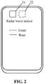
- FIG. 2 is a schematic diagram illustrating a mobile terminal with/including a radar sensor, according to an exemplary embodiment.
- at least one radar sensor may be installed on the mobile terminal.
- the two radar sensors may include a front radar sensor 21 installed on the same side as a front camera in the mobile terminal 2, and a rear radar sensor 22 installed on the same side as a rear camera in the mobile terminal 2.
- the radar sensor may also be installed at other positions of the mobile terminal, which is not limited in any way.
- the front camera and the front radar sensor constitute a functional module group for implementing image processing.
- the rear camera and the rear radar sensor constitute another functional module group for implementing image processing.
- radar sensors installed on different sides of the mobile terminal may transmit radar waves at any angle in front of the different sides of the mobile terminal.
- the front radar sensor 21 installed on the same side as the front camera in the mobile terminal may be configured to transmit a radar wave to an object in image information which can be collected by the front camera.
- the rear radar sensor 22 installed on the same side as the rear camera in the mobile terminal may be configured to transmit a radar wave to an object in image information which can be collected by the rear camera.
- the radar sensor may be disposed on a rotating component of the mobile terminal, and the rotating component in the mobile terminal can drive the radar sensor to change its direction.
- the radar sensor is driven by the rotating component to face a display screen side; or, the radar sensor is driven by the rotating component to transmit a radar wave in a set direction.
- the radar sensor may be disposed on any side of the mobile terminal.
- the echo is a radar wave signal which is formed by the radar wave being reflected by a surface of an object back to the mobile terminal after encountering the object during a transmission process.
- step 102 according to a transmitting parameter of the radar wave and an echo parameter of the echo, spatial structure information of a collected object in the image collection is determined.
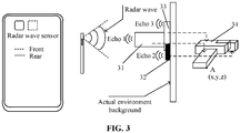
- FIG. 3 is a schematic diagram illustrating an application scenario in which a mobile terminal with a radar sensor transmits a radar wave and receives an echo, according to an exemplary embodiment.
- a mobile terminal with a radar sensor and a collected object are included.
- the collected object includes a first object 31, a second object 32, and a third object 33.
- the mobile terminal After transmitting a radar wave through the radar wave sensor, the mobile terminal will receive a radar wave reflected at one or more positions on an outer surface of the first object 31 to obtain an echo 1, receive a radar wave reflected at one or more positions on an outer surface of the second object 32 to obtain an echo 2, and receive a radar wave reflected at one or more positions on an outer surface of the third object 33 to obtain an echo 3.
- the transmitting parameter may be a time parameter for transmitting the radar wave.
- the transmitting parameter is 10:10:10.
- the echo parameter may be a time parameter for receiving the echo.
- the echo parameter is 10:10:11.
- the transmitting parameter may further include an angle parameter for transmitting the radar wave.
- the echo parameter may also be an angle parameter for receiving the echo.
- the spatial structure information may be coordinate information including different positions of the collected object.
- the coordinate information may be coordinate information in a space coordinate system with a reference point on the mobile terminal as an origin, such as coordinate information in a three-dimensional space coordinate system with a set point of the radar sensor as a reference origin.
- coordinate information of a corner point A of the first object is A (x, y, z).
- x, y, and z respectively correspond to coordinates of three dimensions in a coordinate system.
- the spatial structure information of the collected object may be a set of coordinate information of different positions of the collected object.
- the coordinate information of different positions in the set may be assembled into a virtual space model 34.
- the virtual space model 34 may be configured to display a virtual space model in AR or VR
- the spatial structure information may include a contour shape of the collected object, for example, an outer contour shape.
- the outer contour shape indicated by the spatial structure information is consistent with a shape of the human body.
- an outer contour shape indicated by the spatial structure information is square.
- the spatial structure information may include a size of an outer contour of the collected object, and the like. In short, the shape of the collected object can be roughly described based on the spatial structure information.
- step 103 AR information or VR information of the collected object is obtained according to the spatial structure information and a collected image.
- the image may be a gray image.
- the image includes feature information about colors, textures, and the like related to the collected object.
- the AR information or VR information of the collected object includes space model information of the collected object.
- the AR information may be, after superimposing a real environment and the virtual space model determined according to the spatial structure information and the collected image to the same picture or space, information included in the virtual space model.
- the VR information may be information of/in the virtual space model determined according to the spatial structure information and the collected image.
- the AR information may further include information of other objects other than/besides the collected object.
- the AR information may further include information about cosmetic components on different parts of the face.
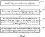
- FIG. 4 is a flow chart showing a method for acquiring AR information or VR information, according to another exemplary embodiment. The method includes the following steps.
- step S1 a mobile phone enters an AR mode or a VR mode.
- step S2 during image collection, the mobile phone transmits a radar wave and receives an echo formed based on the radar wave.
- step S3 the mobile phone determines, according to a transmitting parameter of the radar wave and an echo parameter of the echo, position information of different positions of a collected object in the image collection.
- step S4 the mobile phone obtains AR information or VR information of the collected object according to the position information of different positions of the collected object and a collected image.
- a radar wave is transmitted, and an echo formed based on the radar wave is received; and according to a transmitting parameter of the radar wave and an echo parameter of the echo, spatial structure information of a collected object in the image collection is determined.
- the AR information or VR information of the collected object is obtained according to the spatial structure information and a collected image.
- the spatial structure information of the collected object is directly acquired based on the detection of the radar wave, an error between the spatial structure information and real information of the collected object will be smaller.
- the AR information or the VR information of the collected object obtained according to the spatial structure information and the collected image can more accurately describe the collected object, thereby improving the authenticity of the collected object in an AR or VR scenario, and improving the user experience.
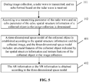
- FIG. 5 is a flow chart showing a method for acquiring AR information or VR information, according to another exemplary embodiment.
- step 103 in which the AR information or VR information of the collected object is obtained according to the spatial structure information and the collected image includes the following steps.
- a three-dimensional space model of the collected object is established according to the spatial structure information and the collected image.
- the three-dimensional space model includes: structural features of the collected object indicated by the spatial structure information and texture features of the collected object in the image collection.
- the three-dimensional space model may be a mathematical model which is generated based on the spatial structure information and the collected image and is capable of reflecting features of the collected object such as a space structure, texture, and the like.
- the mathematical model may be visually displayed on application software of AR or VR
- feature information of each pixel point in the image may be represented by a feature vector (r, g, b).
- r, g, and b represent brightness values corresponding to three channels of red, green, and blue, respectively.
- the image may include feature information of the plurality of pixel points.
- the position information of different positions of the collected object relative to the mobile terminal is represented by (x, y, z).
- x, y, and z are coordinate values of each dimension in a three-dimensional rectangular space coordinate system respectively.
- Each pixel point in the image may correspond to a position of the collected object.
- the spatial structure information may be coordinate information of the plurality of positions.
- the operation that a three-dimensional space model of the collected object is established may include that: position information of different positions of the collected object and feature information of the pixel point are merged.
- position information of a target position of the collected object is represented as coordinates (x, y, z)
- feature information of a corresponding pixel point is represented as a feature vector (r, g, b).
- a feature vector B (x, y, z, r, g, b)
- the feature vector B may be configured to display the three-dimensional space model.
- a set of feature vectors B may be configured to visualize an AR or VR space model of the collected object.
- the texture feature may be a visual feature reflecting the collected object, and may reflect an arrangement property of a surface structure organization having a slow change or a periodic change on the surface of the collected object.
- step 402 the AR information or the VR information is obtained according to the three-dimensional space model.
- the coordinate information of different positions of the collected object and the texture information of the surface of the collected object may be obtained according to the three-dimensional space model.
- FIG. 6 is a schematic diagram illustrating a picture in AR or VR, according to an exemplary embodiment.
- the picture is relatively simple and has only color and texture information.
- FIG. 7 is a schematic diagram illustrating a space model obtained by using a method of an embodiment of the disclosure, according to an exemplary embodiment. It includes not only color and texture information but also space coordinate information. For example, position C on/of the collected object is taken as an example.
- the feature vector corresponding to point C is C (x, y, z, r, g, b), where x, y, and z are the space coordinate information.
- FIG. 8 is a flow chart showing a method for acquiring AR information or VR information, according to another exemplary embodiment. As illustrated in FIG. 8 , the method further includes the following steps.
- step 701 a collection direction for collecting the image is determined.
- step 702 during the image collection, the radar wave is transmitted along the collection direction.
- the direction in which the collected object is located relative to the mobile terminal may be determined first, and a radar wave is transmitted along the direction in which the collected object is located relative to the mobile terminal during image collection.
- the above described front radar sensor is taken as an example. If the collected object is directly in front of the mobile terminal, it is only necessary to control a radar wave to be scanned and transmitted within a certain range directly in front. If the collected object is in a direction that is 30 degrees to the right from a front direction of the mobile terminal, it is only necessary to control a radar wave to be scanned and transmitted within a certain range of the direction that is 30 degrees to the right from the front direction. In this way, a transmission range of the radar wave may be reduced, not only the speed of detecting the spatial structure information of the collected object can be improved, but also the power consumption of the mobile terminal can be saved.
- the operation that the direction in which the collected object is located relative to the mobile terminal is determined may include that: an area range corresponding to the collected image is initially scanned by the radar wave first to roughly determine a direction in which the collected object is located.
- FIG. 9 is a flow chart showing a method for acquiring AR information or VR information, according to another exemplary embodiment.
- a transmitting parameter includes transmitting time
- an echo parameter includes receiving time.
- step 102 in which spatial structure information of the collected object in the image collection is determined according to the transmitting parameter of the radar wave and the echo parameter of the echo includes the following steps.
- step 801 a time difference between the transmitting time and the receiving time is determined.
- the transmitting time is 10:10:10
- the receiving time is 10:10:11
- the time difference is Is.
- step 802 position information of different positions of the collected object relative to the mobile terminal is determined based on the time difference.
- a distance between different positions of the collected object relative to the mobile terminal may be determined based on a transmission speed of the radar wave and the time difference, and then position information of different positions of the collected object relative to the mobile terminal may be determined based on the distance.
- position information of different positions of the collected object relative to the mobile terminal may also be determined based on the distance and an angle of transmitting the radar wave.
- the position information may be coordinate information of different positions of the collected object relative to the mobile terminal.
- step 803 the spatial structure information of the collected object is determined based on the position information.
- the position information includes a plurality of pieces of coordinate information of different positions of the collected object relative to the mobile terminal.
- a set of coordinate information of different positions of the collected object relative to the mobile terminal may constitute spatial structure information of the collected object.
- a first position corresponding to the distance difference greater than a difference threshold is determined according to the first position corresponding to the difference greater than the difference threshold.
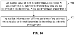
- FIG. 10 is a flow chart showing a method for acquiring AR information or VR information, according to another exemplary embodiment.
- step 801 in which the time difference between the transmitting time and the receiving time is determined includes the following steps.
- step 901 an average value of the time differences, acquired for N consecutive times, between the transmitting time and the receiving time is determined.
- N is a positive integer greater than 1.
- the time differences may be acquired for N consecutive times at a sampling frequency greater than a sampling frequency threshold, and the average value may be determined.
- step 902 the position information of different positions of the collected object relative to the mobile terminal is determined based on the average value.
- position information of different positions of the collected object relative to the mobile terminal is determined based on the average value, so that the determined position information is more accurate.
- FIG. 11 is a block diagram illustrating a device for acquiring AR information or VR information, according to an exemplary embodiment.
- the device is applied to a mobile terminal.
- the device includes a transceiver module 111 and a processing module 112.
- the transceiver module 111 is configured to transmit, during image collection, a radar wave and receive an echo formed based on the radar wave.
- the processing module 112 is configured to: determine, according to a transmitting parameter of the radar wave and an echo parameter of the echo, spatial structure information of a collected object in the image collection; and obtain AR information or VR information of the collected object according to the spatial structure information and a collected image.
- the transceiver module 111 is the transceiver module is further configured to: establish a three-dimensional space model of the collected object according to the spatial structure information and the collected image; the three-dimensional space model including: structural features of the collected object indicated by the spatial structure information and texture features of the collected object in the image collection; and obtain the AR information or the VR information according to the three-dimensional space model.
- the transceiver module 111 is further configured to map the spatial structure information to the collected image, establish a corresponding relationship between position information of a reflection point in the spatial structure information and feature information of a feature point of the collected object in the image, and obtain an AR space model or a VR space model of the collected object.
- the position information of the reflection point includes position information of a reflection point transmitting the radar wave on the collected object relative to the mobile terminal.
- the device further includes a determination module 113.
- the determination module 113 is configured to determine a collection direction for collecting the image.
- the transceiver module 111 is further configured to transmit, during the image collection, the radar wave along the collection direction.
- the transmitting parameter includes transmitting time
- the echo parameter includes receiving time
- the processing module 112 is further configured to: determine a time difference between the transmitting time and the receiving time; determine, based on the time difference, position information of different positions of the collected object relative to the mobile terminal; and determine the spatial structure information of the collected object based on the position information.
- the processing module 112 is further configured to: determine an average value of the time differences, acquired for N consecutive times, between the transmitting time and the receiving time, N being a positive integer greater than 1; and determine, based on the average value, the position information of different positions of the collected object relative to the mobile terminal.
- An embodiment of the disclosure also provides a mobile terminal, which includes:
- the processor is configured to implement, when executing the executable instructions, the method steps described in any embodiment of the disclosure.
- An embodiment of the disclosure also provides a computer-readable storage medium, having a computer program stored thereon.
- the program is executed by a processor to implement the method steps described in any embodiment of the disclosure.
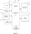
- FIG. 12 is a block diagram illustrating a mobile terminal 600, according to an exemplary embodiment.
- the mobile terminal 600 may be a mobile phone, a computer, a digital broadcast mobile terminal, a messaging device, a gaming console, a tablet, a medical device, exercise equipment, a personal digital assistant, and the like.
- the mobile terminal 600 may include one or more of the following components: a processing component 602, a memory 604, a power component 606, a multimedia component 608, an audio component 610, an input/output (I/O) interface 612, a sensor component 614, and a communication component 616.
- the processing component 602 typically controls overall operations of the mobile terminal 600, such as operations associated with display, telephone calls, data communications, camera operations, and recording operations.
- the processing component 602 may include one or more processors 620 to execute instructions to perform all or part of the steps in the above described methods.
- the processing component 602 may include one or more modules which facilitate the interaction between the processing component 602 and other components.
- the processing component 602 may include a multimedia module to facilitate the interaction between the multimedia component 608 and the processing component 602.
- the memory 604 is configured to store various types of data to support the operation of the mobile terminal 600. Examples of such data include instructions for any applications or methods operated on the mobile terminal 600, contact data, phonebook data, messages, pictures, video, etc.
- the memory 804 may be implemented using any type of volatile or non-volatile memory devices, or a combination thereof, such as a static random access memory (SRAM), an electrically erasable programmable read-only memory (EEPROM), an erasable programmable read-only memory (EPROM), a programmable read-only memory (PROM), a read-only memory (ROM), a magnetic memory, a flash memory, a magnetic or optical disk.
- SRAM static random access memory
- EEPROM electrically erasable programmable read-only memory
- EPROM erasable programmable read-only memory
- PROM programmable read-only memory
- ROM read-only memory
- magnetic memory a magnetic memory
- flash memory a flash memory
- magnetic or optical disk a magnetic
- the power component 606 provides power to various components of the mobile terminal 600.
- the power component 606 may include a power management system, one or more power sources, and any other components associated with the generation, management and distribution of power in the mobile terminal 600.
- the multimedia component 608 includes a screen providing an output interface between the mobile terminal 600 and the user.
- the screen may include a liquid crystal display (LCD) and a touch panel (TP). If the screen includes the TP, the screen may be implemented as a touch screen to receive input signals from the user.
- the TP includes one or more touch sensors to sense touches, swipes and gestures on the TP. The touch sensors may not only sense a boundary of a touch or swipe action, but also sense a period of time and a pressure associated with the touch or swipe action.
- the multimedia component 608 includes a front camera and/or a rear camera.
- the front camera and/or the rear camera may receive an external multimedia datum while the mobile terminal 600 is in an operation mode, such as a photographing mode or a video mode.
- an operation mode such as a photographing mode or a video mode.
- Each of the front camera and the rear camera may be a fixed optical lens system or have focus and optical zoom capability.
- the audio component 610 is configured to output and/or input audio signals.
- the audio component 610 includes a microphone (MIC) configured to receive an external audio signal when the mobile terminal 600 is in an operation mode, such as a call mode, a recording mode, and a voice recognition mode.
- the received audio signal may be further stored in the memory 804 or transmitted via the communication component 616.
- the audio component 610 further includes a speaker to output audio signals.
- the I/O interface 612 provides an interface between the processing component 602 and peripheral interface modules, such as a keyboard, a click wheel, buttons, and the like.
- the buttons may include, but are not limited to, a home button, a volume button, a starting button, and a locking button.
- the sensor component 614 includes one or more sensors to provide status assessments of various aspects of the mobile terminal 600.
- the sensor component 614 may detect an on/off status of the mobile terminal 600, relative positioning of components, e.g., the display and the keypad, of the mobile terminal 600, a change in position of the mobile terminal 600 or a component of the mobile terminal 600, a presence or absence of user contact with the mobile terminal 600, an orientation or an acceleration/deceleration of the mobile terminal 600, and a change in temperature of the mobile terminal 600.
- the sensor component 614 may include a proximity sensor configured to detect the presence of nearby objects without any physical contact.
- the sensor component 814 may also include a light sensor, such as a complementary metal oxide semiconductor (CMOS) or charge coupled device (CCD) image sensor, for use in imaging applications.
- CMOS complementary metal oxide semiconductor
- CCD charge coupled device
- the sensor component 614 may also include an acceleration sensor, a gyroscope sensor, a magnetic sensor, a pressure sensor, or a temperature sensor.
- the communication component 616 is configured to facilitate communication, wired or wirelessly, between the mobile terminal 600 and other devices.
- the mobile terminal 600 may access a wireless network based on a communication standard, such as WiFi, 2G or 3G, or a combination thereof.
- the communication component 616 receives a broadcast signal or broadcast associated information from an external broadcast management system via a broadcast channel.
- the communication component 616 further includes a near field communication (NFC) module to facilitate short-range communications.
- the NFC module may be implemented based on a radio frequency identification (RFID) technology, an infrared data association (IrDA) technology, an ultra-wideband (UWB) technology, a Bluetooth (BT) technology, and other technologies.
- RFID radio frequency identification
- IrDA infrared data association
- UWB ultra-wideband
- BT Bluetooth
- the mobile terminal 600 may be implemented with one or more application specific integrated circuits (ASICs), digital signal processors (DSPs), digital signal processing devices (DSPDs), programmable logic devices (PLDs), field programmable gate arrays (FPGAs), controllers, micro-controllers, microprocessors, or other electronic components, for performing the above described methods.
- ASICs application specific integrated circuits
- DSPs digital signal processors
- DSPDs digital signal processing devices
- PLDs programmable logic devices
- FPGAs field programmable gate arrays
- controllers micro-controllers, microprocessors, or other electronic components, for performing the above described methods.
- non-transitory computer-readable storage medium including instructions, such as included in the memory 604, executable by the processor 620 of the mobile terminal 600, for performing the above described methods.
- the non-transitory computer-readable storage medium may be a ROM, a random access memory (RAM), a compact disc read-only memory (CD-ROM), a magnetic tape, a floppy disc, an optical data storage device, and the like.
- the mobile terminal When instructions in a non-transitory computer-readable storage medium are executed by a processor of a mobile terminal, the mobile terminal is caused to perform the information processing methods described in the above embodiments.
Landscapes
- Engineering & Computer Science (AREA)
- Remote Sensing (AREA)
- Radar, Positioning & Navigation (AREA)
- Physics & Mathematics (AREA)
- General Physics & Mathematics (AREA)
- Computer Networks & Wireless Communication (AREA)
- Theoretical Computer Science (AREA)
- General Engineering & Computer Science (AREA)
- Electromagnetism (AREA)
- Biophysics (AREA)
- Computing Systems (AREA)
- Biomedical Technology (AREA)
- Life Sciences & Earth Sciences (AREA)
- Computational Linguistics (AREA)
- Data Mining & Analysis (AREA)
- Evolutionary Computation (AREA)
- General Health & Medical Sciences (AREA)
- Molecular Biology (AREA)
- Artificial Intelligence (AREA)
- Health & Medical Sciences (AREA)
- Mathematical Physics (AREA)
- Software Systems (AREA)
- Human Computer Interaction (AREA)
- Telephone Function (AREA)
- Radar Systems Or Details Thereof (AREA)
- Processing Or Creating Images (AREA)
Abstract
Description
- The disclosure relates to the technical field of mobile terminals, and more particularly, to a method and device for acquiring augmented reality (AR) information or virtual reality (VR) information, a mobile terminal, and a storage medium.
- An AR technology superimposes a real environment and a virtual object on the same picture or space in real time. A VR technology provides a sense of environmental immersion by simulating a virtual environment. The AR technology and the VR technology are increasingly being applied to different scenarios of daily life. For example, based on the VR technology, people can judge in advance whether a purchased object is suitable for a current space, and can directly see an effect of trying on a certain piece of clothing. The AR technology and the VR technology are increasingly applied to improve the user experience.
- However, in AR and VR scenarios, there are often various errors between AR information or VR information which is obtained by using objects in a real environment based on image processing algorithms such as deep learning and the like and information of the objects in the real environment, and the user experience is affected.
- According to a first aspect of embodiments of the disclosure, a method for acquiring AR information or VR information is provided. The method is applied to a mobile terminal and includes:
- transmitting, during image collection, a radar wave and receiving an echo formed based on the radar wave;
- determining, according to a transmitting parameter of the radar wave and an echo parameter of the echo, spatial structure information of a collected object in the image collection; and
- obtaining AR information or VR information of the collected object according to the spatial structure information and a collected image.
- In an embodiment, obtaining the AR information or VR information of the collected object according to the spatial structure information and the collected image may include:
- establishing a three-dimensional space model of the collected object according to the spatial structure information and the collected image, and when the three-dimensional space model includes: structural features of the collected object indicated by the spatial structure information and texture features of the collected object in the image collection; and
- the AR information or the VR information is obtained according to the three-dimensional space model.
- In an embodiment, the method may further include:
determining a collection direction for collecting the image. - Transmitting the radar wave, during the image collection, may include:
during the image collection, transmitting the radar wave along the collection direction. - In an embodiment, the transmitting parameter may include transmitting time, and the echo parameter may include receiving time.
- Determining, according to the transmitting parameter of the radar wave and the echo parameter of the echo, the spatial structure information of the collected object in the image collection may include:
- determining a time difference between the transmitting time and the receiving time;
- based on the time difference, determining position information of different positions of the collected object relative to the mobile terminal; and
- determining the spatial structure information of the collected object based on the position information.
- In an embodiment, determining the time difference between the transmitting time and the receiving time may include:
determining an average value of the time differences, acquired for N consecutive times, between the transmitting time and the receiving time, N being a positive integer greater than 1. - Determining, based on the time difference, the position information of different positions of the collected object relative to the mobile terminal may include:
- based on the average value, determining the position information of different positions of the collected object relative to the mobile terminal.
- According to a second aspect of embodiments of the disclosure, a device for acquiring AR information or VR information is provided. The device is applied to a mobile terminal. The device includes a transceiver module and a processing module.
- The transceiver module is configured to transmit, during image collection, a radar wave and receive an echo formed based on the radar wave.
- The processing module is configured to: determine, according to a transmitting parameter of the radar wave and an echo parameter of the echo, spatial structure information of a collected object in the image collection, and
obtain AR information or VR information of the collected object according to the spatial structure information and a collected image. - In an embodiment, the transceiver module may be further configured to:
establish a three-dimensional space model of the collected object according to the spatial structure information and the collected image; the three-dimensional space model including: - structural features of the collected object indicated by the spatial structure information and texture features of the collected object in the image collection; and
- obtain the AR information or the VR information according to the three-dimensional space model.
- In an embodiment, the device may further include a determination module, configured to determine a collection direction for collecting the image.
- The transceiver module may be further configured to transmit, during the image collection, the radar wave along the collection direction.
- In an embodiment, the transmitting parameter may include transmitting time, the echo parameter may include receiving time; and the processing module may be further configured to: determine a time difference between the transmitting time and the receiving time; determine, based on the time difference, position information of different positions of the collected object relative to the mobile terminal; and determine the spatial structure information of the collected object based on the position information.
- In an embodiment, the processing module may be further configured to: determine an average value of the time differences, acquired for N consecutive times, between the transmitting time and the receiving time, N being a positive integer greater than 1; and determine, based on the average value, the position information of different positions of the collected object relative to the mobile terminal.
- According to a third aspect of embodiments of the disclosure, a mobile terminal is provided. The mobile terminal includes:
- a processor; and
- a memory configured to store instructions executable by the processor.
- The processor is configured to implement, when executing the executable instructions, the steps described in any one of the above methods.
- According to a fourth aspect of embodiments of the disclosure, a computer-readable storage medium having a computer program stored thereon is provided. The program is executed by a processor to implement the steps described in any one of the above methods.
- The technical solutions in the embodiments of the disclosure include the following beneficial effects.
- In the embodiments of the disclosure, during image collection, a radar wave is transmitted, and an echo formed based on the radar wave is received; and according to a transmitting parameter of the radar wave and an echo parameter of the echo, spatial structure information of a collected object in the image collection is determined. Here, compared with the related art in which a deep learning model is used to obtain spatial structure information, it is more accurate to directly detect the radar wave to acquire the spatial structure information of the collected object. AR information or VR information of the collected object is obtained according to the spatial structure information and a collected image. Here, since the spatial structure information of the collected object is directly acquired based on the detection of the radar wave, an error between the spatial structure information and real information of the collected object will be smaller. The AR information or the VR information of the collected object obtained according to the spatial structure information and the collected image can more accurately describe the collected object, thereby improving the authenticity of the collected object in an AR or VR scene, and improving the user experience.
- It is to be understood that the above general descriptions and detailed descriptions below are only exemplary and explanatory and not intended to limit the disclosure.
- The accompanying drawings, which are incorporated in and constitute a part of this specification, illustrate embodiments consistent with the disclosure and, together with the specification, serve to explain the principles of the disclosure.
-
FIG. 1 is a flow chart showing a method for acquiring AR information or VR information, according to an exemplary embodiment. -
FIG. 2 is a schematic diagram illustrating a mobile terminal with a radar sensor, according to an exemplary embodiment. -
FIG. 3 is a schematic diagram illustrating an application scenario in which a mobile terminal with a radar sensor transmits a radar wave and receives an echo, according to an exemplary embodiment. -
FIG. 4 is a flow chart showing a method for acquiring AR information or VR information, according to another exemplary embodiment. -
FIG. 5 is a flow chart showing a method for acquiring AR information or VR information, according to another exemplary embodiment. -
FIG. 6 is a schematic diagram illustrating a picture in AR or VR, according to an exemplary embodiment. -
FIG. 7 is a schematic diagram illustrating a space model obtained by using a method of an embodiment of the disclosure, according to an exemplary embodiment. -
FIG. 8 is a flow chart showing a method for acquiring AR information or VR information, according to another exemplary embodiment. -
FIG. 9 is a flow chart showing a method for acquiring AR information or VR information, according to another exemplary embodiment. -
FIG. 10 is a flow chart showing a method for acquiring AR information or VR information, according to another exemplary embodiment. -
FIG. 11 is a block diagram illustrating a device for acquiring AR information or VR information, according to an exemplary embodiment. -
FIG. 12 is a block diagram illustrating a mobile terminal, according to an exemplary embodiment. - Reference will now be made in detail to exemplary embodiments, examples of which are illustrated in the accompanying drawings. The following description refers to the accompanying drawings in which the same numbers in different drawings represent the same or similar elements unless otherwise represented. The implementations set forth in the following description of exemplary embodiments do not represent all implementations consistent with the disclosure. Instead, they are merely examples of devices and methods consistent with aspects related to the disclosure as recited in the appended claims.
-
FIG. 1 is a flow chart showing a method for acquiring AR information or VR information, according to an exemplary embodiment. As illustrated inFIG. 1 , the method is applied to a mobile terminal. The method includes the following steps. - In
step 101, during image collection, a radar wave is transmitted, and an echo formed based on the radar wave is received. - Here, the mobile terminal may be a terminal such as a mobile phone, a tablet, a laptop, and the like. The mobile terminal may also be a wearable device, such as a smart watch, a smart bracelet, and the like. In short, any mobile terminal which includes an image collection module and is capable of image collection can be used. Here, an application of AR and/or VR can be run on/in the mobile terminal. The application may be to collect image data through the image collection module.
- Here, the radar wave may be emitted by a radar sensor installed on the mobile terminal. Referring to
FIG. 2, FIG. 2 is a schematic diagram illustrating a mobile terminal with/including a radar sensor, according to an exemplary embodiment. As illustrated inFIG. 2 , at least one radar sensor may be installed on the mobile terminal. For example, two radar sensors are installed on the mobile terminal. The two radar sensors may include afront radar sensor 21 installed on the same side as a front camera in themobile terminal 2, and arear radar sensor 22 installed on the same side as a rear camera in themobile terminal 2. Of course, in other embodiments, the radar sensor may also be installed at other positions of the mobile terminal, which is not limited in any way. - In an embodiment, the front camera and the front radar sensor constitute a functional module group for implementing image processing. The rear camera and the rear radar sensor constitute another functional module group for implementing image processing. In an embodiment, radar sensors installed on different sides of the mobile terminal may transmit radar waves at any angle in front of the different sides of the mobile terminal. For example, the
front radar sensor 21 installed on the same side as the front camera in the mobile terminal may be configured to transmit a radar wave to an object in image information which can be collected by the front camera. Therear radar sensor 22 installed on the same side as the rear camera in the mobile terminal may be configured to transmit a radar wave to an object in image information which can be collected by the rear camera. - In an embodiment, the radar sensor may be disposed on a rotating component of the mobile terminal, and the rotating component in the mobile terminal can drive the radar sensor to change its direction. For example, the radar sensor is driven by the rotating component to face a display screen side; or, the radar sensor is driven by the rotating component to transmit a radar wave in a set direction.
- In practical applications, there may be one or more radar sensors. The radar sensor may be disposed on any side of the mobile terminal.
- Here, the echo is a radar wave signal which is formed by the radar wave being reflected by a surface of an object back to the mobile terminal after encountering the object during a transmission process.
- In
step 102, according to a transmitting parameter of the radar wave and an echo parameter of the echo, spatial structure information of a collected object in the image collection is determined. - Referring to
FIG. 3, FIG. 3 is a schematic diagram illustrating an application scenario in which a mobile terminal with a radar sensor transmits a radar wave and receives an echo, according to an exemplary embodiment. In the application scenario, a mobile terminal with a radar sensor and a collected object are included. The collected object includes afirst object 31, asecond object 32, and athird object 33. After transmitting a radar wave through the radar wave sensor, the mobile terminal will receive a radar wave reflected at one or more positions on an outer surface of thefirst object 31 to obtain anecho 1, receive a radar wave reflected at one or more positions on an outer surface of thesecond object 32 to obtain anecho 2, and receive a radar wave reflected at one or more positions on an outer surface of thethird object 33 to obtain anecho 3. - In an embodiment, the transmitting parameter may be a time parameter for transmitting the radar wave. For example, the transmitting parameter is 10:10:10. The echo parameter may be a time parameter for receiving the echo. For example, the echo parameter is 10:10:11. The transmitting parameter may further include an angle parameter for transmitting the radar wave. The echo parameter may also be an angle parameter for receiving the echo.
- In an embodiment, the spatial structure information may be coordinate information including different positions of the collected object. The coordinate information may be coordinate information in a space coordinate system with a reference point on the mobile terminal as an origin, such as coordinate information in a three-dimensional space coordinate system with a set point of the radar sensor as a reference origin. For example, coordinate information of a corner point A of the first object is A (x, y, z). Here, x, y, and z respectively correspond to coordinates of three dimensions in a coordinate system. Here, the spatial structure information of the collected object may be a set of coordinate information of different positions of the collected object. In an embodiment, the coordinate information of different positions in the set may be assembled into a
virtual space model 34. Thevirtual space model 34 may be configured to display a virtual space model in AR or VR - Here, the spatial structure information may include a contour shape of the collected object, for example, an outer contour shape. For example, if the collected object is a human body, the outer contour shape indicated by the spatial structure information is consistent with a shape of the human body. If the collected object is a square book, an outer contour shape indicated by the spatial structure information is square. In some embodiments, the spatial structure information may include a size of an outer contour of the collected object, and the like. In short, the shape of the collected object can be roughly described based on the spatial structure information.
- In
step 103, AR information or VR information of the collected object is obtained according to the spatial structure information and a collected image. - Here, the image may be a gray image. The image includes feature information about colors, textures, and the like related to the collected object. Here, the AR information or VR information of the collected object includes space model information of the collected object.
- In an embodiment, the AR information may be, after superimposing a real environment and the virtual space model determined according to the spatial structure information and the collected image to the same picture or space, information included in the virtual space model. In another embodiment, the VR information may be information of/in the virtual space model determined according to the spatial structure information and the collected image. It should be noted that the AR information may further include information of other objects other than/besides the collected object. For example, in a face makeup application scenario of AR, the AR information may further include information about cosmetic components on different parts of the face.
- In an embodiment, a mobile phone is taken as an example. Referring to
FIG. 4, FIG. 4 is a flow chart showing a method for acquiring AR information or VR information, according to another exemplary embodiment. The method includes the following steps. - In step S1, a mobile phone enters an AR mode or a VR mode.
- In step S2, during image collection, the mobile phone transmits a radar wave and receives an echo formed based on the radar wave.
- In step S3, the mobile phone determines, according to a transmitting parameter of the radar wave and an echo parameter of the echo, position information of different positions of a collected object in the image collection.
- In step S4, the mobile phone obtains AR information or VR information of the collected object according to the position information of different positions of the collected object and a collected image.
- In this embodiment, during image collection, a radar wave is transmitted, and an echo formed based on the radar wave is received; and according to a transmitting parameter of the radar wave and an echo parameter of the echo, spatial structure information of a collected object in the image collection is determined. Here, compared with the related art in which a deep learning model is used to obtain spatial structure information, it is more accurate to acquire the spatial structure information of the collected object by directly detecting the radar wave to acquire. The AR information or VR information of the collected object is obtained according to the spatial structure information and a collected image. Here, since the spatial structure information of the collected object is directly acquired based on the detection of the radar wave, an error between the spatial structure information and real information of the collected object will be smaller. The AR information or the VR information of the collected object obtained according to the spatial structure information and the collected image can more accurately describe the collected object, thereby improving the authenticity of the collected object in an AR or VR scenario, and improving the user experience.
-
FIG. 5 is a flow chart showing a method for acquiring AR information or VR information, according to another exemplary embodiment. As illustrated inFIG. 5 ,step 103 in which the AR information or VR information of the collected object is obtained according to the spatial structure information and the collected image includes the following steps. - In
step 401, a three-dimensional space model of the collected object is established according to the spatial structure information and the collected image. The three-dimensional space model includes: structural features of the collected object indicated by the spatial structure information and texture features of the collected object in the image collection. - In an embodiment, the three-dimensional space model may be a mathematical model which is generated based on the spatial structure information and the collected image and is capable of reflecting features of the collected object such as a space structure, texture, and the like. The mathematical model may be visually displayed on application software of AR or VR
- In an embodiment, feature information of each pixel point in the image may be represented by a feature vector (r, g, b). Here, r, g, and b represent brightness values corresponding to three channels of red, green, and blue, respectively. The image may include feature information of the plurality of pixel points. In an embodiment, the position information of different positions of the collected object relative to the mobile terminal is represented by (x, y, z). Here, x, y, and z are coordinate values of each dimension in a three-dimensional rectangular space coordinate system respectively. Each pixel point in the image may correspond to a position of the collected object. The spatial structure information may be coordinate information of the plurality of positions.
- In an embodiment, the operation that a three-dimensional space model of the collected object is established may include that: position information of different positions of the collected object and feature information of the pixel point are merged. For example, position information of a target position of the collected object is represented as coordinates (x, y, z), and feature information of a corresponding pixel point is represented as a feature vector (r, g, b). After the position information of the target position of the collected object and the feature information of the pixel point are merged, it may be represented as a feature vector B (x, y, z, r, g, b). The feature vector B may be configured to display the three-dimensional space model. In an embodiment, a set of feature vectors B may be configured to visualize an AR or VR space model of the collected object.
- Here, the texture feature may be a visual feature reflecting the collected object, and may reflect an arrangement property of a surface structure organization having a slow change or a periodic change on the surface of the collected object.
- In
step 402, the AR information or the VR information is obtained according to the three-dimensional space model. - In an embodiment, the coordinate information of different positions of the collected object and the texture information of the surface of the collected object may be obtained according to the three-dimensional space model.
-
FIG. 6 is a schematic diagram illustrating a picture in AR or VR, according to an exemplary embodiment. The picture is relatively simple and has only color and texture information. Referring toFIG. 7, FIG. 7 is a schematic diagram illustrating a space model obtained by using a method of an embodiment of the disclosure, according to an exemplary embodiment. It includes not only color and texture information but also space coordinate information. For example, position C on/of the collected object is taken as an example. The feature vector corresponding to point C is C (x, y, z, r, g, b), where x, y, and z are the space coordinate information. -
FIG. 8 is a flow chart showing a method for acquiring AR information or VR information, according to another exemplary embodiment. As illustrated inFIG. 8 , the method further includes the following steps. - In
step 701, a collection direction for collecting the image is determined. - In an embodiment, it may be determined that a direction in which a collected object is located relative to a mobile terminal is the collection direction.
- In
step 702, during the image collection, the radar wave is transmitted along the collection direction. - In an embodiment, the direction in which the collected object is located relative to the mobile terminal may be determined first, and a radar wave is transmitted along the direction in which the collected object is located relative to the mobile terminal during image collection. For example, the above described front radar sensor is taken as an example. If the collected object is directly in front of the mobile terminal, it is only necessary to control a radar wave to be scanned and transmitted within a certain range directly in front. If the collected object is in a direction that is 30 degrees to the right from a front direction of the mobile terminal, it is only necessary to control a radar wave to be scanned and transmitted within a certain range of the direction that is 30 degrees to the right from the front direction. In this way, a transmission range of the radar wave may be reduced, not only the speed of detecting the spatial structure information of the collected object can be improved, but also the power consumption of the mobile terminal can be saved.
- In some embodiments, the operation that the direction in which the collected object is located relative to the mobile terminal is determined may include that: an area range corresponding to the collected image is initially scanned by the radar wave first to roughly determine a direction in which the collected object is located.
-
FIG. 9 is a flow chart showing a method for acquiring AR information or VR information, according to another exemplary embodiment. A transmitting parameter includes transmitting time, and an echo parameter includes receiving time. As illustrated inFIG. 9 ,step 102 in which spatial structure information of the collected object in the image collection is determined according to the transmitting parameter of the radar wave and the echo parameter of the echo includes the following steps. - In
step 801, a time difference between the transmitting time and the receiving time is determined. - In an embodiment, if the transmitting time is 10:10:10, the receiving time is 10:10:11, and the time difference is Is.
- In
step 802, position information of different positions of the collected object relative to the mobile terminal is determined based on the time difference. - In an embodiment, a distance between different positions of the collected object relative to the mobile terminal may be determined based on a transmission speed of the radar wave and the time difference, and then position information of different positions of the collected object relative to the mobile terminal may be determined based on the distance. In an embodiment, position information of different positions of the collected object relative to the mobile terminal may also be determined based on the distance and an angle of transmitting the radar wave. Here, the position information may be coordinate information of different positions of the collected object relative to the mobile terminal.
- In
step 803, the spatial structure information of the collected object is determined based on the position information. - In an embodiment, the position information includes a plurality of pieces of coordinate information of different positions of the collected object relative to the mobile terminal. A set of coordinate information of different positions of the collected object relative to the mobile terminal may constitute spatial structure information of the collected object.
- In an embodiment, according to a distance difference between distance information of a first position of the collected object relative to the mobile terminal and distance information of a second position adjacent to the first position relative to the mobile terminal, a first position corresponding to the distance difference greater than a difference threshold is determined. Contour information of the collected object is determined according to the first position corresponding to the difference greater than the difference threshold.
-
FIG. 10 is a flow chart showing a method for acquiring AR information or VR information, according to another exemplary embodiment. Referring toFIG. 10 ,step 801 in which the time difference between the transmitting time and the receiving time is determined includes the following steps. - In
step 901, an average value of the time differences, acquired for N consecutive times, between the transmitting time and the receiving time is determined. N is a positive integer greater than 1. - In an embodiment, the time differences may be acquired for N consecutive times at a sampling frequency greater than a sampling frequency threshold, and the average value may be determined.
- In
step 902, the position information of different positions of the collected object relative to the mobile terminal is determined based on the average value. - Here, position information of different positions of the collected object relative to the mobile terminal is determined based on the average value, so that the determined position information is more accurate.
-
FIG. 11 is a block diagram illustrating a device for acquiring AR information or VR information, according to an exemplary embodiment. Referring toFIG. 11 , the device is applied to a mobile terminal. The device includes atransceiver module 111 and aprocessing module 112. - The
transceiver module 111 is configured to transmit, during image collection, a radar wave and receive an echo formed based on the radar wave. - The
processing module 112 is configured to: determine, according to a transmitting parameter of the radar wave and an echo parameter of the echo, spatial structure information of a collected object in the image collection; and
obtain AR information or VR information of the collected object according to the spatial structure information and a collected image. - In an embodiment, the
transceiver module 111 is the transceiver module is further configured to: establish a three-dimensional space model of the collected object according to the spatial structure information and the collected image; the three-dimensional space model including: structural features of the collected object indicated by the spatial structure information and texture features of the collected object in the image collection; and obtain the AR information or the VR information according to the three-dimensional space model. - In an embodiment, the
transceiver module 111 is further configured to map the spatial structure information to the collected image, establish a corresponding relationship between position information of a reflection point in the spatial structure information and feature information of a feature point of the collected object in the image, and obtain an AR space model or a VR space model of the collected object. The position information of the reflection point includes position information of a reflection point transmitting the radar wave on the collected object relative to the mobile terminal. - In an embodiment, the device further includes a
determination module 113. Thedetermination module 113 is configured to determine a collection direction for collecting the image. - The
transceiver module 111 is further configured to transmit, during the image collection, the radar wave along the collection direction. - In an embodiment, the transmitting parameter includes transmitting time, the echo parameter includes receiving time, and the
processing module 112 is further configured to: determine a time difference between the transmitting time and the receiving time; determine, based on the time difference, position information of different positions of the collected object relative to the mobile terminal; and determine the spatial structure information of the collected object based on the position information. - In an embodiment, the
processing module 112 is further configured to: determine an average value of the time differences, acquired for N consecutive times, between the transmitting time and the receiving time, N being a positive integer greater than 1; and determine, based on the average value, the position information of different positions of the collected object relative to the mobile terminal. - An embodiment of the disclosure also provides a mobile terminal, which includes:
- a processor; and
- a memory configured to store instructions executable by the processor.
- The processor is configured to implement, when executing the executable instructions, the method steps described in any embodiment of the disclosure.
- An embodiment of the disclosure also provides a computer-readable storage medium, having a computer program stored thereon. The program is executed by a processor to implement the method steps described in any embodiment of the disclosure.
-
FIG. 12 is a block diagram illustrating amobile terminal 600, according to an exemplary embodiment. For example, themobile terminal 600 may be a mobile phone, a computer, a digital broadcast mobile terminal, a messaging device, a gaming console, a tablet, a medical device, exercise equipment, a personal digital assistant, and the like. - Referring to
FIG. 12 , themobile terminal 600 may include one or more of the following components: aprocessing component 602, amemory 604, apower component 606, amultimedia component 608, anaudio component 610, an input/output (I/O)interface 612, asensor component 614, and acommunication component 616. - The
processing component 602 typically controls overall operations of themobile terminal 600, such as operations associated with display, telephone calls, data communications, camera operations, and recording operations. Theprocessing component 602 may include one ormore processors 620 to execute instructions to perform all or part of the steps in the above described methods. Moreover, theprocessing component 602 may include one or more modules which facilitate the interaction between theprocessing component 602 and other components. For example, theprocessing component 602 may include a multimedia module to facilitate the interaction between themultimedia component 608 and theprocessing component 602. - The
memory 604 is configured to store various types of data to support the operation of themobile terminal 600. Examples of such data include instructions for any applications or methods operated on themobile terminal 600, contact data, phonebook data, messages, pictures, video, etc. The memory 804 may be implemented using any type of volatile or non-volatile memory devices, or a combination thereof, such as a static random access memory (SRAM), an electrically erasable programmable read-only memory (EEPROM), an erasable programmable read-only memory (EPROM), a programmable read-only memory (PROM), a read-only memory (ROM), a magnetic memory, a flash memory, a magnetic or optical disk. - The
power component 606 provides power to various components of themobile terminal 600. Thepower component 606 may include a power management system, one or more power sources, and any other components associated with the generation, management and distribution of power in themobile terminal 600. - The
multimedia component 608 includes a screen providing an output interface between themobile terminal 600 and the user. In some embodiments, the screen may include a liquid crystal display (LCD) and a touch panel (TP). If the screen includes the TP, the screen may be implemented as a touch screen to receive input signals from the user. The TP includes one or more touch sensors to sense touches, swipes and gestures on the TP. The touch sensors may not only sense a boundary of a touch or swipe action, but also sense a period of time and a pressure associated with the touch or swipe action. In some embodiments, themultimedia component 608 includes a front camera and/or a rear camera. The front camera and/or the rear camera may receive an external multimedia datum while themobile terminal 600 is in an operation mode, such as a photographing mode or a video mode. Each of the front camera and the rear camera may be a fixed optical lens system or have focus and optical zoom capability. - The
audio component 610 is configured to output and/or input audio signals. For example, theaudio component 610 includes a microphone (MIC) configured to receive an external audio signal when themobile terminal 600 is in an operation mode, such as a call mode, a recording mode, and a voice recognition mode. The received audio signal may be further stored in the memory 804 or transmitted via thecommunication component 616. In some embodiments, theaudio component 610 further includes a speaker to output audio signals. - The I/
O interface 612 provides an interface between theprocessing component 602 and peripheral interface modules, such as a keyboard, a click wheel, buttons, and the like. The buttons may include, but are not limited to, a home button, a volume button, a starting button, and a locking button. - The
sensor component 614 includes one or more sensors to provide status assessments of various aspects of themobile terminal 600. For example, thesensor component 614 may detect an on/off status of themobile terminal 600, relative positioning of components, e.g., the display and the keypad, of themobile terminal 600, a change in position of themobile terminal 600 or a component of themobile terminal 600, a presence or absence of user contact with themobile terminal 600, an orientation or an acceleration/deceleration of themobile terminal 600, and a change in temperature of themobile terminal 600. Thesensor component 614 may include a proximity sensor configured to detect the presence of nearby objects without any physical contact. The sensor component 814 may also include a light sensor, such as a complementary metal oxide semiconductor (CMOS) or charge coupled device (CCD) image sensor, for use in imaging applications. In some embodiments, thesensor component 614 may also include an acceleration sensor, a gyroscope sensor, a magnetic sensor, a pressure sensor, or a temperature sensor. - The
communication component 616 is configured to facilitate communication, wired or wirelessly, between themobile terminal 600 and other devices. Themobile terminal 600 may access a wireless network based on a communication standard, such as WiFi, 2G or 3G, or a combination thereof. In one exemplary embodiment, thecommunication component 616 receives a broadcast signal or broadcast associated information from an external broadcast management system via a broadcast channel. In one exemplary embodiment, thecommunication component 616 further includes a near field communication (NFC) module to facilitate short-range communications. For example, the NFC module may be implemented based on a radio frequency identification (RFID) technology, an infrared data association (IrDA) technology, an ultra-wideband (UWB) technology, a Bluetooth (BT) technology, and other technologies. - In exemplary embodiments, the
mobile terminal 600 may be implemented with one or more application specific integrated circuits (ASICs), digital signal processors (DSPs), digital signal processing devices (DSPDs), programmable logic devices (PLDs), field programmable gate arrays (FPGAs), controllers, micro-controllers, microprocessors, or other electronic components, for performing the above described methods. - In exemplary embodiments, there is also provided a non-transitory computer-readable storage medium including instructions, such as included in the
memory 604, executable by theprocessor 620 of themobile terminal 600, for performing the above described methods. For example, the non-transitory computer-readable storage medium may be a ROM, a random access memory (RAM), a compact disc read-only memory (CD-ROM), a magnetic tape, a floppy disc, an optical data storage device, and the like. - When instructions in a non-transitory computer-readable storage medium are executed by a processor of a mobile terminal, the mobile terminal is caused to perform the information processing methods described in the above embodiments.
- Other embodiments of the disclosure will be apparent to those skilled in the art from consideration of the specification and practice of the disclosure disclosed here. The disclosure is intended to cover any variations, uses, or adaptations of the disclosure following the general principles thereof and including such departures from the disclosure as come within known or customary practice in the art. It is intended that the specification and examples be considered as exemplary only, with a true scope and spirit of the disclosure being indicated by the following claims.
- It will be appreciated that the disclosure is not limited to the exact construction that has been described above and illustrated in the accompanying drawings, and that various modifications and changes can be made without departing from the scope thereof. It is intended that the scope of the disclosure only be limited by the appended claims.
Claims (12)
- A method for acquiring augmented reality, AR, information or virtual reality, VR, information, wherein the method is applied to a mobile terminal and comprises:transmitting (101), during image collection, a radar wave and receiving an echo formed based on the radar wave; and characterized bydetermining (102), according to a transmitting parameter of the radar wave and an echo parameter of the echo, spatial structure information of a collected object in the image collection; andobtaining (103) AR information or VR information of the collected object according to the spatial structure information and a collected image.
- The method of claim 1, wherein obtaining the AR information or VR information of the collected object according to the spatial structure information and the collected image comprises:establishing (401) a three-dimensional space model of the collected object according to the spatial structure information and the collected image; wherein the three-dimensional space model comprises: structural features of the collected object indicated by the spatial structure information and texture features of the collected object in the image collection; andobtaining (402) the AR information or the VR information according to the three-dimensional space model.
- The method of claim 1 or 2, further comprising:determining (701) a collection direction for collecting the image,wherein transmitting, during the image collection, the radar wave comprises:
transmitting (702), during the image collection, the radar wave along the collection direction. - The method of claim 3, wherein the transmitting parameter comprises transmitting time, and the echo parameter comprises receiving time;
wherein determining, according to the transmitting parameter of the radar wave and the echo parameter of the echo, the spatial structure information of the collected object in the image collection comprises:determining (801) a time difference between the transmitting time and the receiving time;determining (802), based on the time difference, position information of different positions of the collected object relative to the mobile terminal; anddetermining (803) the spatial structure information of the collected object based on the position information. - The method of claim 4, wherein determining the time difference between the transmitting time and the receiving time comprises:determining (901) an average value of the time differences, acquired for N consecutive times, between the transmitting time and the receiving time; wherein N is a positive integer greater than 1; andwherein the determining, based on the time difference, the position information of different positions of the collected object relative to the mobile terminal comprises:
determining (902), based on the average value, the position information of different positions of the collected object relative to the mobile terminal. - A device for acquiring augmented reality, AR, information or virtual reality, VR, information, wherein the device is applied to a mobile terminal and comprises: a transceiver module (111) and a processing module (112);wherein the transceiver module (111) is configured to transmit, during image collection, a radar wave and receive an echo formed based on the radar wave;and characterized in that the processing module (112) is configured to: determine, according to a transmitting parameter of the radar wave and an echo parameter of the echo, spatial structure information of a collected object in the image collection; andobtain AR information or VR information of the collected object according to the spatial structure information and a collected image.
- The device of claim 6, wherein the transceiver module (111) is further configured to:establish a three-dimensional space model of the collected object according to the spatial structure information and the collected image; wherein the three-dimensional space model comprising: structural features of the collected object indicated by the spatial structure information and texture features of the collected object in the image collection; andobtain the AR information or the VR information according to the three-dimensional space model.
- The device of claim 6 or 7, further comprising: a determination module (113), configured to determine a collection direction for collecting the image,
wherein the transceiver module (111) is further configured to transmit, during the image collection, the radar wave along the collection direction. - The device of claim 8, wherein the transmitting parameter comprises transmitting time, the echo parameter comprises receiving time;
wherein the processing module (112) is further configured to: determine a time difference between the transmitting time and the receiving time; determine, based on the time difference, position information of different positions of the collected object relative to the mobile terminal; and determine the spatial structure information of the collected object based on the position information. - The device of claim 9, wherein the processing module (112) is further configured to:determine an average value of the time differences, acquired for N consecutive times, between the transmitting time and the receiving time; wherein N is a positive integer greater than 1; anddetermine, based on the average value, the position information of different positions of the collected object relative to the mobile terminal.
- A mobile terminal, comprising:a processor (602); anda memory (604) configured to store instructions executable by the processor,wherein the processor is configured to implement, when executing the executable instructions, the method steps of any one of claims 1 to 5.
- A computer-readable storage medium storing a computer program, the program being executed by a processor to implement the method steps of any one of claims 1 to 5.
Applications Claiming Priority (1)
| Application Number | Priority Date | Filing Date | Title |
|---|---|---|---|
| CN202010054123.9A CN113138660B (en) | 2020-01-17 | 2020-01-17 | Information acquisition method and device, mobile terminal and storage medium |
Publications (2)
| Publication Number | Publication Date |
|---|---|
| EP3851874A1 true EP3851874A1 (en) | 2021-07-21 |
| EP3851874B1 EP3851874B1 (en) | 2025-03-12 |
Family
ID=70802787
Family Applications (1)
| Application Number | Title | Priority Date | Filing Date |
|---|---|---|---|
| EP20176137.6A Active EP3851874B1 (en) | 2020-01-17 | 2020-05-22 | Method and device for acquiring augmented reality or virtual reality information |
Country Status (3)
| Country | Link |
|---|---|
| US (1) | US11656351B2 (en) |
| EP (1) | EP3851874B1 (en) |
| CN (1) | CN113138660B (en) |
Families Citing this family (2)
| Publication number | Priority date | Publication date | Assignee | Title |
|---|---|---|---|---|
| CN114076958A (en) * | 2020-08-17 | 2022-02-22 | 华为技术有限公司 | Electromagnetic wave imaging method, device and system |
| JP2025508289A (en) * | 2023-01-17 | 2025-03-26 | グーグル エルエルシー | Ultra-wideband radar device for controlling cloud-based gaming |
Citations (1)
| Publication number | Priority date | Publication date | Assignee | Title |
|---|---|---|---|---|
| CN107392996A (en) * | 2017-07-11 | 2017-11-24 | 中国科学院电子学研究所苏州研究院 | A kind of SAR target properties based on virtual reality technology characterize and display methods |
Family Cites Families (22)
| Publication number | Priority date | Publication date | Assignee | Title |
|---|---|---|---|---|
| US6177903B1 (en) * | 1999-06-14 | 2001-01-23 | Time Domain Corporation | System and method for intrusion detection using a time domain radar array |
| DE102010051207B4 (en) * | 2010-11-12 | 2015-07-23 | Fraunhofer-Gesellschaft zur Förderung der angewandten Forschung e.V. | Device and method for three-dimensional imaging of a relative to the sensor arrangement moving object |
| US9269152B1 (en) * | 2011-09-07 | 2016-02-23 | Amazon Technologies, Inc. | Object detection with distributed sensor array |
| WO2013096704A1 (en) * | 2011-12-20 | 2013-06-27 | Sadar 3D, Inc. | Systems, apparatus, and methods for acquisition and use of image data |
| US9196067B1 (en) * | 2013-03-05 | 2015-11-24 | Amazon Technologies, Inc. | Application specific tracking of projection surfaces |
| WO2015160289A1 (en) * | 2014-04-14 | 2015-10-22 | Saab Vricon Systems Ab | Method and system for rendering a synthetic aperture radar image |
| WO2016187483A1 (en) * | 2015-05-20 | 2016-11-24 | Brian Mullins | Light-based radar system for augmented reality |
| KR102561099B1 (en) * | 2016-09-23 | 2023-07-28 | 삼성전자주식회사 | ToF(time of flight) capturing apparatus and method for reducing of depth distortion caused by multiple reflection thereof |
| FR3056765B1 (en) * | 2016-09-27 | 2018-12-07 | Centre National D'etudes Spatiales | METHOD FOR CHARACTERIZATION BY A RADAR INSTRUMENT DEFINING A TARGET IN POSITION AND IN REFLECTIVITY |
| LU93302B1 (en) * | 2016-11-14 | 2018-06-18 | Iee Sa | Polarimetric Radar System and Method for Classifying Objects ahead of a Vehicle |
| WO2018099400A1 (en) * | 2016-11-29 | 2018-06-07 | 苏州宝时得电动工具有限公司 | Augmented reality-based interior design system and method |
| CN108510593B (en) * | 2017-02-28 | 2021-07-13 | 中兴通讯股份有限公司 | A method and device for collecting three-dimensional space model based on electromagnetic waves |
| CN107066092B (en) * | 2017-03-20 | 2020-04-03 | 上海大学 | VR running space dynamic detection and parametric virtual scene reconstruction system and method |
| WO2019008716A1 (en) * | 2017-07-06 | 2019-01-10 | マクセル株式会社 | Non-visible measurement device and non-visible measurement method |
| CN107284379A (en) * | 2017-07-28 | 2017-10-24 | 合肥芯福传感器技术有限公司 | AR optical projection systems and projecting method for vehicle safe driving |
| US10852419B2 (en) * | 2017-10-20 | 2020-12-01 | Texas Instruments Incorporated | System and method for camera radar fusion |
| CN107972585A (en) * | 2017-11-30 | 2018-05-01 | 惠州市德赛西威汽车电子股份有限公司 | Scene rebuilding System and method for is looked around with reference to the adaptive 3 D of radar information |
| CN109451294B (en) * | 2018-09-26 | 2023-07-14 | 深圳达闼科技控股有限公司 | 3D display method, system, device, electronic equipment and storage medium |
| CN109782283A (en) * | 2019-03-13 | 2019-05-21 | 昆山煜壶信息技术有限公司 | Millimetre-wave radar imaging method based on premodulated AIC |
| CN110415342B (en) * | 2019-08-02 | 2023-04-18 | 深圳市唯特视科技有限公司 | Three-dimensional point cloud reconstruction device and method based on multi-fusion sensor |
| CN110674696B (en) * | 2019-08-28 | 2023-01-13 | 珠海格力电器股份有限公司 | Monitoring method, device, system, monitoring equipment and readable storage medium |
| CN114911221B (en) * | 2021-02-09 | 2023-11-28 | 北京小米机器人技术有限公司 | Robot control method, device and robot |
-
2020
- 2020-01-17 CN CN202010054123.9A patent/CN113138660B/en active Active
- 2020-05-11 US US16/871,908 patent/US11656351B2/en active Active
- 2020-05-22 EP EP20176137.6A patent/EP3851874B1/en active Active
Patent Citations (1)
| Publication number | Priority date | Publication date | Assignee | Title |
|---|---|---|---|---|
| CN107392996A (en) * | 2017-07-11 | 2017-11-24 | 中国科学院电子学研究所苏州研究院 | A kind of SAR target properties based on virtual reality technology characterize and display methods |
Non-Patent Citations (2)
| Title |
|---|
| NGUYEN LAM ET AL: "Augmented reality using ultra-wideband radar imagery", RADAR SENSOR TECHNOLOGY XV, SPIE, 1000 20TH ST. BELLINGHAM WA 98225-6705 USA, vol. 8021, no. 1, 13 May 2011 (2011-05-13), pages 1 - 6, XP060014604, DOI: 10.1117/12.883285 * |
| ZHURAVLEV A V ET AL: "On the use of augmented reality devices for subsurface radar imaging", 2016 PROGRESS IN ELECTROMAGNETIC RESEARCH SYMPOSIUM (PIERS), IEEE, 8 August 2016 (2016-08-08), pages 2132 - 2136, XP032997044, DOI: 10.1109/PIERS.2016.7734890 * |
Also Published As
| Publication number | Publication date |
|---|---|
| US11656351B2 (en) | 2023-05-23 |
| CN113138660B (en) | 2024-09-27 |
| US20210223386A1 (en) | 2021-07-22 |
| EP3851874B1 (en) | 2025-03-12 |
| CN113138660A (en) | 2021-07-20 |
Similar Documents
| Publication | Publication Date | Title |
|---|---|---|
| EP3825960B1 (en) | Method and device for obtaining localization information | |
| EP3511864A1 (en) | Method and apparatus for synthesizing virtual and real objects | |
| CN110097576B (en) | Motion information determination method of image feature point, task execution method and equipment | |
| CN109584362B (en) | Three-dimensional model construction method and device, electronic equipment and storage medium | |
| CN114019473A (en) | Object detection method and device, electronic device and storage medium | |
| CN106325521B (en) | Test virtual reality head shows the method and device of device software | |
| CN106778773B (en) | Method and device for locating objects in pictures | |
| CN110930351A (en) | Light spot detection method and device and electronic equipment | |
| CN113645414B (en) | Method and device for generating water ripple special effect video, electronic equipment and storage medium | |
| CN111179628B (en) | Positioning method and device for automatic driving vehicle, electronic equipment and storage medium | |
| EP3745086A1 (en) | Method and device for creating indoor environment map | |
| CN113345000A (en) | Depth detection method and device, electronic equipment and storage medium | |
| CN112184787A (en) | Image registration method and device, electronic equipment and storage medium | |
| CN110807769B (en) | Image display control method and device | |
| US11656351B2 (en) | Method and mobile device for acquiring AR or VR information by averaging pixel values | |
| CN113469036A (en) | Living body detection method and apparatus, electronic device, and storage medium | |
| CN113344999A (en) | Depth detection method and device, electronic equipment and storage medium | |
| CN109934168B (en) | Face image mapping method and device | |
| CN109978759B (en) | Image processing method and device and training method and device of image generation network | |
| CN111127541B (en) | Vehicle size determination method, device and storage medium | |
| CN113865481B (en) | Object size measurement method, device and storage medium | |
| WO2022222379A1 (en) | Position determination method and apparatus, electronic device and storage medium | |
| CN114782560A (en) | Image color detection method, image color detection apparatus, image color detection device, image color detection apparatus, storage medium, and program product | |
| CN112399080A (en) | Video processing method, device, terminal and computer readable storage medium | |
| EP4572373A1 (en) | Wireless access point deployment method, apparatus, electronic device and readable storage medium |
Legal Events
| Date | Code | Title | Description |
|---|---|---|---|
| PUAI | Public reference made under article 153(3) epc to a published international application that has entered the european phase |
Free format text: ORIGINAL CODE: 0009012 |
|
| STAA | Information on the status of an ep patent application or granted ep patent |
Free format text: STATUS: THE APPLICATION HAS BEEN PUBLISHED |
|
| AK | Designated contracting states |
Kind code of ref document: A1 Designated state(s): AL AT BE BG CH CY CZ DE DK EE ES FI FR GB GR HR HU IE IS IT LI LT LU LV MC MK MT NL NO PL PT RO RS SE SI SK SM TR |
|
| STAA | Information on the status of an ep patent application or granted ep patent |
Free format text: STATUS: REQUEST FOR EXAMINATION WAS MADE |
|
| 17P | Request for examination filed |
Effective date: 20210804 |
|
| RBV | Designated contracting states (corrected) |
Designated state(s): AL AT BE BG CH CY CZ DE DK EE ES FI FR GB GR HR HU IE IS IT LI LT LU LV MC MK MT NL NO PL PT RO RS SE SI SK SM TR |
|
| STAA | Information on the status of an ep patent application or granted ep patent |
Free format text: STATUS: EXAMINATION IS IN PROGRESS |
|
| RIC1 | Information provided on ipc code assigned before grant |
Ipc: G01S 13/89 20060101ALI20240524BHEP Ipc: G01S 13/86 20060101ALI20240524BHEP Ipc: G01S 13/42 20060101ALI20240524BHEP Ipc: G01S 13/08 20060101AFI20240524BHEP |
|
| 17Q | First examination report despatched |
Effective date: 20240605 |
|
| GRAP | Despatch of communication of intention to grant a patent |
Free format text: ORIGINAL CODE: EPIDOSNIGR1 |
|
| STAA | Information on the status of an ep patent application or granted ep patent |
Free format text: STATUS: GRANT OF PATENT IS INTENDED |
|
| INTG | Intention to grant announced |
Effective date: 20241018 |
|
| GRAS | Grant fee paid |
Free format text: ORIGINAL CODE: EPIDOSNIGR3 |
|
| GRAA | (expected) grant |
Free format text: ORIGINAL CODE: 0009210 |
|
| STAA | Information on the status of an ep patent application or granted ep patent |
Free format text: STATUS: THE PATENT HAS BEEN GRANTED |
|
| P01 | Opt-out of the competence of the unified patent court (upc) registered |
Free format text: CASE NUMBER: APP_1942/2025 Effective date: 20250113 |
|
| AK | Designated contracting states |
Kind code of ref document: B1 Designated state(s): AL AT BE BG CH CY CZ DE DK EE ES FI FR GB GR HR HU IE IS IT LI LT LU LV MC MK MT NL NO PL PT RO RS SE SI SK SM TR |
|
| REG | Reference to a national code |
Ref country code: GB Ref legal event code: FG4D |
|
| REG | Reference to a national code |
Ref country code: CH Ref legal event code: EP |
|
| REG | Reference to a national code |
Ref country code: DE Ref legal event code: R096 Ref document number: 602020047502 Country of ref document: DE |
|
| REG | Reference to a national code |
Ref country code: IE Ref legal event code: FG4D |
|
| PG25 | Lapsed in a contracting state [announced via postgrant information from national office to epo] |
Ref country code: RS Free format text: LAPSE BECAUSE OF FAILURE TO SUBMIT A TRANSLATION OF THE DESCRIPTION OR TO PAY THE FEE WITHIN THE PRESCRIBED TIME-LIMIT Effective date: 20250612 |
|
| PG25 | Lapsed in a contracting state [announced via postgrant information from national office to epo] |
Ref country code: FI Free format text: LAPSE BECAUSE OF FAILURE TO SUBMIT A TRANSLATION OF THE DESCRIPTION OR TO PAY THE FEE WITHIN THE PRESCRIBED TIME-LIMIT Effective date: 20250312 |
|
| PGFP | Annual fee paid to national office [announced via postgrant information from national office to epo] |
Ref country code: DE Payment date: 20250521 Year of fee payment: 6 |
|
| PG25 | Lapsed in a contracting state [announced via postgrant information from national office to epo] |
Ref country code: ES Free format text: LAPSE BECAUSE OF FAILURE TO SUBMIT A TRANSLATION OF THE DESCRIPTION OR TO PAY THE FEE WITHIN THE PRESCRIBED TIME-LIMIT Effective date: 20250312 |
|
| REG | Reference to a national code |
Ref country code: LT Ref legal event code: MG9D |
|
| PG25 | Lapsed in a contracting state [announced via postgrant information from national office to epo] |
Ref country code: NO Free format text: LAPSE BECAUSE OF FAILURE TO SUBMIT A TRANSLATION OF THE DESCRIPTION OR TO PAY THE FEE WITHIN THE PRESCRIBED TIME-LIMIT Effective date: 20250612 |
|
| PG25 | Lapsed in a contracting state [announced via postgrant information from national office to epo] |
Ref country code: HR Free format text: LAPSE BECAUSE OF FAILURE TO SUBMIT A TRANSLATION OF THE DESCRIPTION OR TO PAY THE FEE WITHIN THE PRESCRIBED TIME-LIMIT Effective date: 20250312 |
|
| REG | Reference to a national code |
Ref country code: NL Ref legal event code: MP Effective date: 20250312 |
|
| PG25 | Lapsed in a contracting state [announced via postgrant information from national office to epo] |
Ref country code: LV Free format text: LAPSE BECAUSE OF FAILURE TO SUBMIT A TRANSLATION OF THE DESCRIPTION OR TO PAY THE FEE WITHIN THE PRESCRIBED TIME-LIMIT Effective date: 20250312 |
|
| PG25 | Lapsed in a contracting state [announced via postgrant information from national office to epo] |
Ref country code: BG Free format text: LAPSE BECAUSE OF FAILURE TO SUBMIT A TRANSLATION OF THE DESCRIPTION OR TO PAY THE FEE WITHIN THE PRESCRIBED TIME-LIMIT Effective date: 20250312 Ref country code: GR Free format text: LAPSE BECAUSE OF FAILURE TO SUBMIT A TRANSLATION OF THE DESCRIPTION OR TO PAY THE FEE WITHIN THE PRESCRIBED TIME-LIMIT Effective date: 20250613 |
|
| REG | Reference to a national code |
Ref country code: AT Ref legal event code: MK05 Ref document number: 1775433 Country of ref document: AT Kind code of ref document: T Effective date: 20250312 |
|
| PG25 | Lapsed in a contracting state [announced via postgrant information from national office to epo] |
Ref country code: NL Free format text: LAPSE BECAUSE OF FAILURE TO SUBMIT A TRANSLATION OF THE DESCRIPTION OR TO PAY THE FEE WITHIN THE PRESCRIBED TIME-LIMIT Effective date: 20250312 |
|
| PG25 | Lapsed in a contracting state [announced via postgrant information from national office to epo] |
Ref country code: SE Free format text: LAPSE BECAUSE OF FAILURE TO SUBMIT A TRANSLATION OF THE DESCRIPTION OR TO PAY THE FEE WITHIN THE PRESCRIBED TIME-LIMIT Effective date: 20250312 |
|
| PG25 | Lapsed in a contracting state [announced via postgrant information from national office to epo] |
Ref country code: SM Free format text: LAPSE BECAUSE OF FAILURE TO SUBMIT A TRANSLATION OF THE DESCRIPTION OR TO PAY THE FEE WITHIN THE PRESCRIBED TIME-LIMIT Effective date: 20250312 |
|
| PG25 | Lapsed in a contracting state [announced via postgrant information from national office to epo] |
Ref country code: PT Free format text: LAPSE BECAUSE OF FAILURE TO SUBMIT A TRANSLATION OF THE DESCRIPTION OR TO PAY THE FEE WITHIN THE PRESCRIBED TIME-LIMIT Effective date: 20250714 |
|
| PG25 | Lapsed in a contracting state [announced via postgrant information from national office to epo] |
Ref country code: IT Free format text: LAPSE BECAUSE OF FAILURE TO SUBMIT A TRANSLATION OF THE DESCRIPTION OR TO PAY THE FEE WITHIN THE PRESCRIBED TIME-LIMIT Effective date: 20250312 Ref country code: PL Free format text: LAPSE BECAUSE OF FAILURE TO SUBMIT A TRANSLATION OF THE DESCRIPTION OR TO PAY THE FEE WITHIN THE PRESCRIBED TIME-LIMIT Effective date: 20250312 |
|
| PG25 | Lapsed in a contracting state [announced via postgrant information from national office to epo] |
Ref country code: AT Free format text: LAPSE BECAUSE OF FAILURE TO SUBMIT A TRANSLATION OF THE DESCRIPTION OR TO PAY THE FEE WITHIN THE PRESCRIBED TIME-LIMIT Effective date: 20250312 |
|
| PG25 | Lapsed in a contracting state [announced via postgrant information from national office to epo] |
Ref country code: CZ Free format text: LAPSE BECAUSE OF FAILURE TO SUBMIT A TRANSLATION OF THE DESCRIPTION OR TO PAY THE FEE WITHIN THE PRESCRIBED TIME-LIMIT Effective date: 20250312 Ref country code: EE Free format text: LAPSE BECAUSE OF FAILURE TO SUBMIT A TRANSLATION OF THE DESCRIPTION OR TO PAY THE FEE WITHIN THE PRESCRIBED TIME-LIMIT Effective date: 20250312 |
|
| PG25 | Lapsed in a contracting state [announced via postgrant information from national office to epo] |
Ref country code: RO Free format text: LAPSE BECAUSE OF FAILURE TO SUBMIT A TRANSLATION OF THE DESCRIPTION OR TO PAY THE FEE WITHIN THE PRESCRIBED TIME-LIMIT Effective date: 20250312 |
|
| PG25 | Lapsed in a contracting state [announced via postgrant information from national office to epo] |
Ref country code: SK Free format text: LAPSE BECAUSE OF FAILURE TO SUBMIT A TRANSLATION OF THE DESCRIPTION OR TO PAY THE FEE WITHIN THE PRESCRIBED TIME-LIMIT Effective date: 20250312 |
|
| PG25 | Lapsed in a contracting state [announced via postgrant information from national office to epo] |
Ref country code: IS Free format text: LAPSE BECAUSE OF FAILURE TO SUBMIT A TRANSLATION OF THE DESCRIPTION OR TO PAY THE FEE WITHIN THE PRESCRIBED TIME-LIMIT Effective date: 20250712 |
|
| REG | Reference to a national code |
Ref country code: DE Ref legal event code: R097 Ref document number: 602020047502 Country of ref document: DE |
|
| REG | Reference to a national code |
Ref country code: CH Ref legal event code: H13 Free format text: ST27 STATUS EVENT CODE: U-0-0-H10-H13 (AS PROVIDED BY THE NATIONAL OFFICE) Effective date: 20251223 |
|
| PG25 | Lapsed in a contracting state [announced via postgrant information from national office to epo] |
Ref country code: DK Free format text: LAPSE BECAUSE OF FAILURE TO SUBMIT A TRANSLATION OF THE DESCRIPTION OR TO PAY THE FEE WITHIN THE PRESCRIBED TIME-LIMIT Effective date: 20250312 |
|
| PG25 | Lapsed in a contracting state [announced via postgrant information from national office to epo] |
Ref country code: LU Free format text: LAPSE BECAUSE OF NON-PAYMENT OF DUE FEES Effective date: 20250522 |
|
| PLBE | No opposition filed within time limit |
Free format text: ORIGINAL CODE: 0009261 |
|
| STAA | Information on the status of an ep patent application or granted ep patent |
Free format text: STATUS: NO OPPOSITION FILED WITHIN TIME LIMIT |
|
| PG25 | Lapsed in a contracting state [announced via postgrant information from national office to epo] |
Ref country code: CH Free format text: LAPSE BECAUSE OF NON-PAYMENT OF DUE FEES Effective date: 20250531 |
|
| REG | Reference to a national code |
Ref country code: CH Ref legal event code: L10 Free format text: ST27 STATUS EVENT CODE: U-0-0-L10-L00 (AS PROVIDED BY THE NATIONAL OFFICE) Effective date: 20260121 |
|
| REG | Reference to a national code |
Ref country code: BE Ref legal event code: MM Effective date: 20250531 |
|
| PG25 | Lapsed in a contracting state [announced via postgrant information from national office to epo] |
Ref country code: MC Free format text: LAPSE BECAUSE OF FAILURE TO SUBMIT A TRANSLATION OF THE DESCRIPTION OR TO PAY THE FEE WITHIN THE PRESCRIBED TIME-LIMIT Effective date: 20250312 |
|
| 26N | No opposition filed |
Effective date: 20251215 |
|
| GBPC | Gb: european patent ceased through non-payment of renewal fee |
Effective date: 20250612 |
|
| PG25 | Lapsed in a contracting state [announced via postgrant information from national office to epo] |
Ref country code: GB Free format text: LAPSE BECAUSE OF NON-PAYMENT OF DUE FEES Effective date: 20250612 |
|
| PG25 | Lapsed in a contracting state [announced via postgrant information from national office to epo] |
Ref country code: IE Free format text: LAPSE BECAUSE OF NON-PAYMENT OF DUE FEES Effective date: 20250522 |
|
| PG25 | Lapsed in a contracting state [announced via postgrant information from national office to epo] |
Ref country code: BE Free format text: LAPSE BECAUSE OF NON-PAYMENT OF DUE FEES Effective date: 20250531 |
|
| PG25 | Lapsed in a contracting state [announced via postgrant information from national office to epo] |
Ref country code: FR Free format text: LAPSE BECAUSE OF NON-PAYMENT OF DUE FEES Effective date: 20250531 |