EP3851783B1 - Aufnahme- und ausbringungsvorrichtung für nutzlasten an einer flugmaschine - Google Patents
Aufnahme- und ausbringungsvorrichtung für nutzlasten an einer flugmaschine Download PDFInfo
- Publication number
- EP3851783B1 EP3851783B1 EP21151262.9A EP21151262A EP3851783B1 EP 3851783 B1 EP3851783 B1 EP 3851783B1 EP 21151262 A EP21151262 A EP 21151262A EP 3851783 B1 EP3851783 B1 EP 3851783B1
- Authority
- EP
- European Patent Office
- Prior art keywords
- housing
- payload
- cavity
- accommodation
- side surfaces
- Prior art date
- Legal status (The legal status is an assumption and is not a legal conclusion. Google has not performed a legal analysis and makes no representation as to the accuracy of the status listed.)
- Active
Links
Images

Classifications
-
- B—PERFORMING OPERATIONS; TRANSPORTING
- B64—AIRCRAFT; AVIATION; COSMONAUTICS
- B64D—EQUIPMENT FOR FITTING IN OR TO AIRCRAFT; FLIGHT SUITS; PARACHUTES; ARRANGEMENT OR MOUNTING OF POWER PLANTS OR PROPULSION TRANSMISSIONS IN AIRCRAFT
- B64D7/00—Arrangement of military equipment, e.g. armaments, armament accessories or military shielding, in aircraft; Adaptations of armament mountings for aircraft
- B64D7/08—Arrangement of rocket launchers
-
- B—PERFORMING OPERATIONS; TRANSPORTING
- B64—AIRCRAFT; AVIATION; COSMONAUTICS
- B64D—EQUIPMENT FOR FITTING IN OR TO AIRCRAFT; FLIGHT SUITS; PARACHUTES; ARRANGEMENT OR MOUNTING OF POWER PLANTS OR PROPULSION TRANSMISSIONS IN AIRCRAFT
- B64D1/00—Dropping, ejecting, releasing or receiving articles, liquids, or the like, in flight
- B64D1/02—Dropping, ejecting, or releasing articles
- B64D1/04—Dropping, ejecting, or releasing articles the articles being explosive, e.g. bombs
- B64D1/06—Bomb releasing; Bomb doors
-
- F—MECHANICAL ENGINEERING; LIGHTING; HEATING; WEAPONS; BLASTING
- F41—WEAPONS
- F41F—APPARATUS FOR LAUNCHING PROJECTILES OR MISSILES FROM BARRELS, e.g. CANNONS; LAUNCHERS FOR ROCKETS OR TORPEDOES; HARPOON GUNS
- F41F3/00—Rocket or torpedo launchers
- F41F3/04—Rocket or torpedo launchers for rockets
- F41F3/06—Rocket or torpedo launchers for rockets from aircraft
-
- B—PERFORMING OPERATIONS; TRANSPORTING
- B64—AIRCRAFT; AVIATION; COSMONAUTICS
- B64C—AEROPLANES; HELICOPTERS
- B64C9/00—Adjustable control surfaces or members, e.g. rudders
Definitions
- Various embodiments generally relate to a device for accommodating and deploying payloads on a flying machine.
- US 3 026 773 A describes an apparatus for launching rockets from aircraft comprising a plurality of elongated panel-like access doors nominally forming part of the envelope of a generally conical, forwardly tapering section of the aircraft and tractable means in the airplane envelope exposing the forward ends of said doors within the aircraft envelope at the forward ends thereof.
- US 2 937 573 A describes a bombing arrangement for an aircraft, said aircraft having a fuselage and a bomb bay disposed in the lower portion of said fuselage substantially along a vertical plane passing through the centerline of said aircraft, said fuselage having a lower wall surface, a bomb bay door capable of carrying bombs, closely fitted in said bomb bay and having a lower wall complementary to the contour of and abutting said lower wall surface of said fuselage, means pivotally supporting a forward portion of said door from a point forward of the forward end of said door, and above said lower fuselage wall surface, means for lowering the aft end of said door when bombs are to be dispersed therefrom.
- US 2003/192992 A1 describes a radial sonobuoy launch system comprising a clam-shell launch tube and method for launching a sonobuoy.
- the clam-shell launch tube radially releases a sonobuoy and the clam-shell launch tube is reloaded during flight.
- the sonobuoys are pneumatically ejected about parallel to the airstream.
- a pressure boundary structure having a door and a gate, maintains cabin pressure during reloading and launching. Support arms and drive arms evenly distribute the ejection accelerations from the firing mechanism and guide the trajectory of the sonobuoy during release.
- a clam-shell launch tube is capable of launching a multitude of differently sized sonobuoys.
- GB 2 077 678 A describes a device for carrying under aircraft multiple loads disposed at variable distances between centres. A variation in the distances between centres of the loads is obtained by rotating the load supports about longitudinal axes by means of bearings incorporated in the frame structure of said carrier device.
- US 4 106 389 A describes an aircraft having a fuselage with a forward cockpit, an aft mounted fin, and an upper deck extending between the two, there being a weapon launcher assembly of elongated form with a forward end through which rocket propelled weapons are launched, a rearward end through which rocket exhaust is dissipated, and an upper deck extending between the two, the launcher being pivotable between a stowed position wherein it lies with its upper deck smoothly continuous with the upper deck of the fuselage and an extended weapon launch position wherein the weapons can be launched clear of the forward cockpit.
- the device has at least one housing, wherein the housing has at least two opposite first side surfaces. The two opposite side surfaces extend over at least a partial region of the length of a payload to be accommodated. The payload to be accommodated is removably held between the first two side surfaces of the housing.
- the housing is at least partially arranged in a cavity on an outer surface of a flying machine.
- the cavity has at least one externally open first opening.
- the housing can be at least partially moved out of the cavity for launching and/or receiving the payload to be accommodated.
- at least one of the side surfaces has at least one closable pressure relief opening.
- the housing has a rail-guided accommodation device arranged on the first side surfaces, wherein at least one payload to be accommodated is removably held at least on two sides by the accommodation device.
- the invention is based on the idea of providing an accommodation and deployment device, which may also be referred to as a carrying and deploying device, for a flying machine or aircraft in which the payload can be deployed without significantly influencing the radar signature of the aircraft.
- the launching device has a housing, hereinafter also referred to as a tunnel launcher, which preferably forms the aerodynamic contour of the flying machine or of a fighter aircraft on one side, while the rest of the carrying and launching device is housed in the aircraft structure in cavities or weapons bays adapted to the weapon in shape and size.
- the housing or the tunnel launcher is used similarly to so-called drop launchers at the moment of launching of the payload or the round from the aircraft or the strake and allows the launching of the payload or the weapon using the driving force of the drive of the payload or the weapon while deflecting the exhaust jet away from the flying machine or the aircraft.
- the cavity has a closing device.
- the cavity can be sealed aerodynamically and/or in relation to radar radiation when launching or extracting the at least one payload from the housing. This has the advantage of improving the radar signature of the aircraft.
- the housing has at least one further side surface.
- the further side surface connects the two first side surfaces of the housing in the area of the lateral edge of the first side surface lying in the direction of the outer surface of the flying machine.
- the outer surface of the flying machine can be sealed aerodynamically and/or in relation to radar radiation by means of the further side surface of the housing when the housing is fully housed in the cavity.
- the first two side surfaces and the further side surface thus preferably form three side surfaces of a housing.
- the housing may have a further side surface, which at least partially connects the three side surfaces together at the end and forms a fourth side of the housing.
- the further side surface at the end is used, when launching a payload such as a guided missile, to give this a forward-directed acceleration impulse to mitigate the short-term aerodynamic resistance of the delivery device and preferably to give a further impulse away from the trajectory of the missile.
- At least one of the side surfaces has at least one closable pressure relief opening.
- the pressure relief opening can be either on one of the side surfaces or the further side surface arranged at the end.
- the task of the pressure relief opening is, on the one hand, to guide the exhaust gases away from the flying machine when a payload is ejected or launched, such as a guided missile.
- the pressure relief opening is used to convey an acceleration impulse to the payload to be launched.
- the housing has a rail-guided accommodation device arranged on the first side surfaces.
- the accommodation device By means of the accommodation device, at least one payload to be accommodated is releasably held by the accommodation device at least on two sides.
- the accommodation device allows the payload to be accommodated and enables launching of the payload using the guidance of the rails of the accommodation device.
- the accommodation device is designed to accommodate a number of payloads. After releasing the payload, such as a weapon, the housing or tunnel launcher can be moved back to its strake position and another payload, for example a weapon, is fed in internally.
- the payload such as a weapon
- the housing or tunnel launcher can be moved back to its strake position and another payload, for example a weapon, is fed in internally.
- the rail-guided accommodation device has at least two retaining rails.
- the retaining rails are used to hold the payload preferably on two opposite side surfaces and to guide it during the launching.
- the payload is designed here so that at least two opposite side surfaces of the payload have grooves or the like which correspond to the retaining rails.
- the retaining rail has a plurality of regularly arranged retaining elements.
- the retaining rails may be formed by preferably at least partially regularly arranged retaining elements or retaining blocks.
- the retaining elements can be guided, for example, as sliding blocks or as guide rollers.
- the distance between the at least two retaining rails of the rail-guided accommodation device and/or the position of the at least two retaining rails in the cavity can be controllably varied.
- the distance of the retaining rails can preferably be varied. This also has the advantage that the distance of the retaining rails can be extended, for example, to accommodate the payload.
- the cavity has a magazine for accommodating a plurality of payloads and the payloads contained in the magazine can be fed into the housing by means of a feed mechanism.
- a feed mechanism for accommodating a plurality of payloads and the payloads contained in the magazine can be fed into the housing by means of a feed mechanism.
- the plurality of payloads can be launched sequentially or in pairs by means of the rail-guided accommodation device.
- the object is achieved by a system with a device as described herein and a payload for accommodating and deploying by an aircraft with an elongated payload body, with at least one outer surface which has at least two elongated recesses extending over a portion of the length of the payload body.
- the payload can be accommodated in a previously described device.
- the tunnel concept allows the accommodation of existing payloads, such as weapons, without the need for specific new developments for them.
- Figure 1 shows a first embodiment of a device 10 for accommodating and deploying a payload 11 on a flying machine 12.
- the device 10 has a housing 13 with two opposite first side surfaces 14 - in the figure only one of the two side surfaces 14 is visible due to the two-dimensional representation.
- the side surfaces 14 extend over at least a portion of the length L of the payload 11.
- the payload 11 shown in the housing 13 is smaller than would be possible in principle due to the dimension.
- the payload 11 is detachably held between the first two side surfaces 14 of the housing 13.
- the housing 13 In a retracted state, the housing 13 is arranged in a cavity 15 on an outer surface of the flying machine 12.
- the cavity 15 has an externally open first opening 16.
- the housing 13 is at least partially movable out of the cavity 15 for deploying and/or receiving the payload 11 to be accommodated.
- Figure 1 also shows, in addition to the retracted state, the state of the housing 13 which is forced out or pushed out of the strake.
- the housing 13 has a pressure relief opening 18 for discharging the exhaust gas jet.
- the pressure relief opening 18 is arranged on a further side surface 17 which connects the first two side surfaces 14 at the bottom.
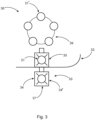
- Figure 2 shows a further embodiment of a device 20 for accommodation and deployment of a plurality of payloads 21 on a flying machine 22.
- a first payload 21 is arranged in the housing 23. Further payloads 21 are arranged in a magazine 29 in the cavity 25, via which the further payloads 21 can be fed into the housing 23 after deploying the first payload 21.
- the housing 23 also has a pressure relief opening 28 at the bottom of the side surfaces 24.
- Figure 3 shows a further representation of an embodiment of a device 30 for accommodation and deployment of a plurality of payloads 31, 31 ⁇ on an aircraft 32.
- the device 30 has a round magazine 39, in which further payloads 31 ⁇ are arranged.
- the further payloads 31 ⁇ can be reloaded into the housing 33 after the deployment of the first payload 31.
- the housing 33 has two first side surfaces 34, 34 ⁇ and a further side surface 37 connecting the first two side surfaces 34, 34'.
Landscapes
- Engineering & Computer Science (AREA)
- Aviation & Aerospace Engineering (AREA)
- General Engineering & Computer Science (AREA)
- Aiming, Guidance, Guns With A Light Source, Armor, Camouflage, And Targets (AREA)
- Radar Systems Or Details Thereof (AREA)
Claims (10)
- Vorrichtung (10, 20, 30) zum Aufnehmen und Ausbringen mindestens einer Nutzlast (11, 21, 31, 31') an einer Flugmaschine (12, 22, 32), mit:mindestens einem Gehäuse (13, 23, 33),wobei das Gehäuse (13, 23, 33) mindestens zwei gegenüberliegende erste Seitenflächen (14, 24, 34, 34') aufweist, die sich über mindestens einen Abschnitt der Länge (L) einer aufzunehmenden Nutzlast (11, 21, 31, 31') erstrecken,wobei die aufzunehmende Nutzlast (11, 21, 31, 31') lösbar zwischen den ersten zwei Seitenflächen (14, 24, 34) des Gehäuses (13, 23, 33) gehalten wird,wobei das Gehäuse (13, 23, 33) zumindest teilweise in einem Hohlraum (15, 25, 35) an einer Außenfläche einer Flugmaschine (12, 22, 32) angeordnet ist,wobei der Hohlraum (15, 25, 35) mindestens eine nach außen offene erste Öffnung (16) aufweist,wobei das Gehäuse (13, 23, 33) zumindest teilweise aus dem Hohlraum (15, 25, 35) herausbewegt werden kann, um die aufzunehmende Nutzlast (11, 21, 31, 31') auszubringen und/oder aufzunehmen,wobei mindestens eine der Seitenflächen (14, 24, 34, 34') mindestens eine verschließbare Druckentlastungsöffnung (18, 28) aufweist,dadurch gekennzeichnet, dassdas Gehäuse (13, 23, 33) eine an den ersten Seitenflächen (14, 24, 34, 34') angeordnete schienengeführte Aufnahmevorrichtung aufweist, undmindestens eine aufzunehmende Nutzlast (11, 21, 31, 31') mindestens an zwei Seiten durch die Aufnahmevorrichtung abnehmbar gehalten wird.
- Vorrichtung (10, 20, 30) nach Anspruch 1,
wobei der Hohlraum (15, 25, 35) eine Schließvorrichtung aufweist, mit der der Hohlraum (15, 25, 35) zum Zeitpunkt der Ausbringung oder Herausnahme mindestens einer Nutzlast (11, 21, 31, 31') aus dem Gehäuse (13, 23, 33) aerodynamisch und/oder gegen Radarstrahlung abgedichtet werden kann. - Vorrichtung (10, 20, 30) nach Anspruch 1,
wobei das Gehäuse (13, 23, 33) mindestens eine weitere Seitenfläche (17, 37) aufweist, die die zwei ersten Seitenflächen (14, 24, 34) des Gehäuses (13, 23, 33) im Bereich der Seitenkante der ersten Seitenflächen (14, 24, 34) in Richtung der Außenfläche der Flugmaschine (12, 22, 32) verbindet, und wobei die Außenfläche der Flugmaschine (12, 22, 32) mittels der weiteren Seitenfläche (17, 37) des Gehäuses aerodynamisch und/oder gegen Radarstrahlung abgedichtet werden kann, wenn das Gehäuse (13, 23, 33) vollständig in dem Hohlraum (15, 25, 35) untergebracht ist. - Vorrichtung nach einem der vorhergehenden Ansprüche,
wobei die schienengeführte Aufnahmevorrichtung dazu ausgelegt ist, eine Vielzahl von Nutzlasten (11, 21, 31, 31') aufzunehmen. - Vorrichtung nach einem der vorhergehenden Ansprüche,
wobei die schienengeführte Aufnahmevorrichtung mindestens zwei Halteschienen aufweist. - Vorrichtung nach Anspruch 5,
wobei die Halteschiene eine Vielzahl von regelmäßig angeordneten Halteelementen aufweist. - Vorrichtung nach Anspruch 6,
wobei der Abstand zwischen den mindestens zwei Halteschienen der schienengeführten Aufnahmevorrichtung oder die Position der mindestens zwei Halteschienen im Hohlraum (15) steuerbar verändert werden kann. - Vorrichtung nach einem der vorhergehenden Ansprüche,
wobei der Hohlraum (15, 25, 35) ein Magazin (29, 39) zur Aufnahme einer Vielzahl von Nutzlasten (11, 21, 31, 31') aufweist und die im Magazin (29, 39) enthaltenen Nutzlasten (11, 21, 31, 31') durch einen Vorschubmechanismus in das Gehäuse (13, 23, 33) einführbar sind. - Vorrichtung nach Anspruch 8,
wobei die Vielzahl von Nutzlasten (11, 21, 31, 31') mittels der schienengeführten Aufnahmevorrichtung nacheinander oder paarweise ausgebracht werden können. - System, umfassend:eine Vorrichtung nach einem der vorhergehenden Ansprüche, undeine Nutzlast zur Unterbringung und Ausbringung auf einer Flugmaschine, wobei die Nutzlast Folgendes aufweist:
einen länglichen Nutzlastkörper, mit mindestens einer Außenfläche, die mindestens zwei längliche Ausnehmungen aufweist, die sich über einen Abschnitt der Länge des Nutzlastkörpers erstrecken und die in der Vorrichtung nach einem der vorhergehenden Ansprüche aufgenommen werden können.
Applications Claiming Priority (1)
| Application Number | Priority Date | Filing Date | Title |
|---|---|---|---|
| DE202020100183.3U DE202020100183U1 (de) | 2020-01-14 | 2020-01-14 | Aufnahme- und Absetzvorrichtung von Nutzlasten an einem Fluggerät |
Publications (2)
| Publication Number | Publication Date |
|---|---|
| EP3851783A1 EP3851783A1 (de) | 2021-07-21 |
| EP3851783B1 true EP3851783B1 (de) | 2024-08-28 |
Family
ID=69527289
Family Applications (1)
| Application Number | Title | Priority Date | Filing Date |
|---|---|---|---|
| EP21151262.9A Active EP3851783B1 (de) | 2020-01-14 | 2021-01-13 | Aufnahme- und ausbringungsvorrichtung für nutzlasten an einer flugmaschine |
Country Status (3)
| Country | Link |
|---|---|
| US (1) | US20210214081A1 (de) |
| EP (1) | EP3851783B1 (de) |
| DE (1) | DE202020100183U1 (de) |
Families Citing this family (1)
| Publication number | Priority date | Publication date | Assignee | Title |
|---|---|---|---|---|
| DE102021124570B4 (de) | 2021-09-22 | 2023-05-11 | Airbus Defence and Space GmbH | Vorrichtung zum Aufnehmen und zum Absetzen einer Nutzlast an einem Fluggerät |
Citations (1)
| Publication number | Priority date | Publication date | Assignee | Title |
|---|---|---|---|---|
| US4106389A (en) * | 1976-05-14 | 1978-08-15 | British Aircraft Corporation | Aircraft weapon mountings |
Family Cites Families (5)
| Publication number | Priority date | Publication date | Assignee | Title |
|---|---|---|---|---|
| US3026773A (en) * | 1950-01-26 | 1962-03-27 | Lockheed Aircraft Corp | Rocket nose installation |
| US2937573A (en) * | 1956-06-28 | 1960-05-24 | Martin Co | Bombing apparatus |
| FR2484360A1 (fr) * | 1980-06-13 | 1981-12-18 | Alkan R & Cie | Dispositif d'emport sous avion de charges multiples a entr'axe variable |
| US4637292A (en) * | 1985-12-23 | 1987-01-20 | Lockheed Corporation | Rotary launcher system for an aircraft |
| US6679454B2 (en) * | 2002-04-15 | 2004-01-20 | The Boeing Company | Radial sonobuoy launcher |
-
2020
- 2020-01-14 DE DE202020100183.3U patent/DE202020100183U1/de active Active
-
2021
- 2021-01-13 US US17/147,814 patent/US20210214081A1/en not_active Abandoned
- 2021-01-13 EP EP21151262.9A patent/EP3851783B1/de active Active
Patent Citations (1)
| Publication number | Priority date | Publication date | Assignee | Title |
|---|---|---|---|---|
| US4106389A (en) * | 1976-05-14 | 1978-08-15 | British Aircraft Corporation | Aircraft weapon mountings |
Also Published As
| Publication number | Publication date |
|---|---|
| EP3851783A1 (de) | 2021-07-21 |
| DE202020100183U1 (de) | 2020-01-24 |
| US20210214081A1 (en) | 2021-07-15 |
Similar Documents
| Publication | Publication Date | Title |
|---|---|---|
| EP3749574B1 (de) | Schienenabschussmunitionsfreisetzung | |
| US8979029B2 (en) | System for carrying and dropping loads for a transport airplane | |
| US6679454B2 (en) | Radial sonobuoy launcher | |
| US4637292A (en) | Rotary launcher system for an aircraft | |
| US4681013A (en) | Rotary launcher system for an aircraft | |
| US9776719B2 (en) | Air-launchable container for deploying air vehicle | |
| WO2008010226A1 (en) | Air vehicle and deployable wing arrangement therefor | |
| US3517584A (en) | Stores ejection means | |
| US11255648B2 (en) | Projectile with a range extending wing assembly | |
| EP3837170B1 (de) | Anordnung zum abschuss einer nutzlast und verfahren zum abschuss einer nutzlast | |
| US6688209B1 (en) | Multi-configuration munition rack | |
| EP2652438B1 (de) | Projektil mit einem antriebssystem und einem startmotor auf den gegenüberliegenden seiten der nutzlast und verfahren dafür | |
| US10578398B1 (en) | Drone deployment apparatus for accommodating aircraft fuselages | |
| EP3851783B1 (de) | Aufnahme- und ausbringungsvorrichtung für nutzlasten an einer flugmaschine | |
| US4409880A (en) | Missile stowage and launcher system | |
| US11623730B2 (en) | Canopy separation systems and methods for an aircraft | |
| US7185846B1 (en) | Asymmetrical control surface system for tube-launched air vehicles | |
| US20150284080A1 (en) | Special forces replenishment vehicle | |
| US7040210B2 (en) | Apparatus and method for restraining and releasing a control surface | |
| EP1917495B1 (de) | Ausstossbare aerodynamische stabilisierungs- und steuerungsvorrichtung | |
| US20250093129A1 (en) | Aircraft weapons pod including rail launcher | |
| RU2712403C1 (ru) | Устройство для транспортировки и сброса грузов для транспортного летательного аппарата | |
| WO2024003902A1 (en) | Air intake module for a projectile | |
| US4283988A (en) | Tail carriage of stores | |
| EP4632310A1 (de) | Verfahren zur steuerung von lenkflugkörpern sowie lenkflugkörper und flugzeug |
Legal Events
| Date | Code | Title | Description |
|---|---|---|---|
| PUAI | Public reference made under article 153(3) epc to a published international application that has entered the european phase |
Free format text: ORIGINAL CODE: 0009012 |
|
| STAA | Information on the status of an ep patent application or granted ep patent |
Free format text: STATUS: THE APPLICATION HAS BEEN PUBLISHED |
|
| AK | Designated contracting states |
Kind code of ref document: A1 Designated state(s): AL AT BE BG CH CY CZ DE DK EE ES FI FR GB GR HR HU IE IS IT LI LT LU LV MC MK MT NL NO PL PT RO RS SE SI SK SM TR |
|
| STAA | Information on the status of an ep patent application or granted ep patent |
Free format text: STATUS: REQUEST FOR EXAMINATION WAS MADE |
|
| 17P | Request for examination filed |
Effective date: 20220117 |
|
| RBV | Designated contracting states (corrected) |
Designated state(s): AL AT BE BG CH CY CZ DE DK EE ES FI FR GB GR HR HU IE IS IT LI LT LU LV MC MK MT NL NO PL PT RO RS SE SI SK SM TR |
|
| GRAP | Despatch of communication of intention to grant a patent |
Free format text: ORIGINAL CODE: EPIDOSNIGR1 |
|
| STAA | Information on the status of an ep patent application or granted ep patent |
Free format text: STATUS: GRANT OF PATENT IS INTENDED |
|
| INTG | Intention to grant announced |
Effective date: 20240429 |
|
| GRAS | Grant fee paid |
Free format text: ORIGINAL CODE: EPIDOSNIGR3 |
|
| GRAA | (expected) grant |
Free format text: ORIGINAL CODE: 0009210 |
|
| STAA | Information on the status of an ep patent application or granted ep patent |
Free format text: STATUS: THE PATENT HAS BEEN GRANTED |
|
| AK | Designated contracting states |
Kind code of ref document: B1 Designated state(s): AL AT BE BG CH CY CZ DE DK EE ES FI FR GB GR HR HU IE IS IT LI LT LU LV MC MK MT NL NO PL PT RO RS SE SI SK SM TR |
|
| REG | Reference to a national code |
Ref country code: CH Ref legal event code: EP |
|
| REG | Reference to a national code |
Ref country code: DE Ref legal event code: R096 Ref document number: 602021017715 Country of ref document: DE |
|
| REG | Reference to a national code |
Ref country code: IE Ref legal event code: FG4D |
|
| REG | Reference to a national code |
Ref country code: LT Ref legal event code: MG9D |
|
| PG25 | Lapsed in a contracting state [announced via postgrant information from national office to epo] |
Ref country code: NO Free format text: LAPSE BECAUSE OF FAILURE TO SUBMIT A TRANSLATION OF THE DESCRIPTION OR TO PAY THE FEE WITHIN THE PRESCRIBED TIME-LIMIT Effective date: 20241128 |
|
| REG | Reference to a national code |
Ref country code: AT Ref legal event code: MK05 Ref document number: 1718366 Country of ref document: AT Kind code of ref document: T Effective date: 20240828 |
|
| PG25 | Lapsed in a contracting state [announced via postgrant information from national office to epo] |
Ref country code: NL Free format text: LAPSE BECAUSE OF FAILURE TO SUBMIT A TRANSLATION OF THE DESCRIPTION OR TO PAY THE FEE WITHIN THE PRESCRIBED TIME-LIMIT Effective date: 20240828 Ref country code: PT Free format text: LAPSE BECAUSE OF FAILURE TO SUBMIT A TRANSLATION OF THE DESCRIPTION OR TO PAY THE FEE WITHIN THE PRESCRIBED TIME-LIMIT Effective date: 20241230 Ref country code: GR Free format text: LAPSE BECAUSE OF FAILURE TO SUBMIT A TRANSLATION OF THE DESCRIPTION OR TO PAY THE FEE WITHIN THE PRESCRIBED TIME-LIMIT Effective date: 20241129 Ref country code: PL Free format text: LAPSE BECAUSE OF FAILURE TO SUBMIT A TRANSLATION OF THE DESCRIPTION OR TO PAY THE FEE WITHIN THE PRESCRIBED TIME-LIMIT Effective date: 20240828 Ref country code: FI Free format text: LAPSE BECAUSE OF FAILURE TO SUBMIT A TRANSLATION OF THE DESCRIPTION OR TO PAY THE FEE WITHIN THE PRESCRIBED TIME-LIMIT Effective date: 20240828 |
|
| PG25 | Lapsed in a contracting state [announced via postgrant information from national office to epo] |
Ref country code: BG Free format text: LAPSE BECAUSE OF FAILURE TO SUBMIT A TRANSLATION OF THE DESCRIPTION OR TO PAY THE FEE WITHIN THE PRESCRIBED TIME-LIMIT Effective date: 20240828 |
|
| PG25 | Lapsed in a contracting state [announced via postgrant information from national office to epo] |
Ref country code: LV Free format text: LAPSE BECAUSE OF FAILURE TO SUBMIT A TRANSLATION OF THE DESCRIPTION OR TO PAY THE FEE WITHIN THE PRESCRIBED TIME-LIMIT Effective date: 20240828 |
|
| REG | Reference to a national code |
Ref country code: NL Ref legal event code: MP Effective date: 20240828 |
|
| PG25 | Lapsed in a contracting state [announced via postgrant information from national office to epo] |
Ref country code: AT Free format text: LAPSE BECAUSE OF FAILURE TO SUBMIT A TRANSLATION OF THE DESCRIPTION OR TO PAY THE FEE WITHIN THE PRESCRIBED TIME-LIMIT Effective date: 20240828 Ref country code: IS Free format text: LAPSE BECAUSE OF FAILURE TO SUBMIT A TRANSLATION OF THE DESCRIPTION OR TO PAY THE FEE WITHIN THE PRESCRIBED TIME-LIMIT Effective date: 20241228 |
|
| PG25 | Lapsed in a contracting state [announced via postgrant information from national office to epo] |
Ref country code: HR Free format text: LAPSE BECAUSE OF FAILURE TO SUBMIT A TRANSLATION OF THE DESCRIPTION OR TO PAY THE FEE WITHIN THE PRESCRIBED TIME-LIMIT Effective date: 20240828 |
|
| PG25 | Lapsed in a contracting state [announced via postgrant information from national office to epo] |
Ref country code: ES Free format text: LAPSE BECAUSE OF FAILURE TO SUBMIT A TRANSLATION OF THE DESCRIPTION OR TO PAY THE FEE WITHIN THE PRESCRIBED TIME-LIMIT Effective date: 20240828 Ref country code: RS Free format text: LAPSE BECAUSE OF FAILURE TO SUBMIT A TRANSLATION OF THE DESCRIPTION OR TO PAY THE FEE WITHIN THE PRESCRIBED TIME-LIMIT Effective date: 20241128 |
|
| PG25 | Lapsed in a contracting state [announced via postgrant information from national office to epo] |
Ref country code: RS Free format text: LAPSE BECAUSE OF FAILURE TO SUBMIT A TRANSLATION OF THE DESCRIPTION OR TO PAY THE FEE WITHIN THE PRESCRIBED TIME-LIMIT Effective date: 20241128 Ref country code: PT Free format text: LAPSE BECAUSE OF FAILURE TO SUBMIT A TRANSLATION OF THE DESCRIPTION OR TO PAY THE FEE WITHIN THE PRESCRIBED TIME-LIMIT Effective date: 20241230 Ref country code: PL Free format text: LAPSE BECAUSE OF FAILURE TO SUBMIT A TRANSLATION OF THE DESCRIPTION OR TO PAY THE FEE WITHIN THE PRESCRIBED TIME-LIMIT Effective date: 20240828 Ref country code: NO Free format text: LAPSE BECAUSE OF FAILURE TO SUBMIT A TRANSLATION OF THE DESCRIPTION OR TO PAY THE FEE WITHIN THE PRESCRIBED TIME-LIMIT Effective date: 20241128 Ref country code: NL Free format text: LAPSE BECAUSE OF FAILURE TO SUBMIT A TRANSLATION OF THE DESCRIPTION OR TO PAY THE FEE WITHIN THE PRESCRIBED TIME-LIMIT Effective date: 20240828 Ref country code: LV Free format text: LAPSE BECAUSE OF FAILURE TO SUBMIT A TRANSLATION OF THE DESCRIPTION OR TO PAY THE FEE WITHIN THE PRESCRIBED TIME-LIMIT Effective date: 20240828 Ref country code: IS Free format text: LAPSE BECAUSE OF FAILURE TO SUBMIT A TRANSLATION OF THE DESCRIPTION OR TO PAY THE FEE WITHIN THE PRESCRIBED TIME-LIMIT Effective date: 20241228 Ref country code: HR Free format text: LAPSE BECAUSE OF FAILURE TO SUBMIT A TRANSLATION OF THE DESCRIPTION OR TO PAY THE FEE WITHIN THE PRESCRIBED TIME-LIMIT Effective date: 20240828 Ref country code: GR Free format text: LAPSE BECAUSE OF FAILURE TO SUBMIT A TRANSLATION OF THE DESCRIPTION OR TO PAY THE FEE WITHIN THE PRESCRIBED TIME-LIMIT Effective date: 20241129 Ref country code: FI Free format text: LAPSE BECAUSE OF FAILURE TO SUBMIT A TRANSLATION OF THE DESCRIPTION OR TO PAY THE FEE WITHIN THE PRESCRIBED TIME-LIMIT Effective date: 20240828 Ref country code: ES Free format text: LAPSE BECAUSE OF FAILURE TO SUBMIT A TRANSLATION OF THE DESCRIPTION OR TO PAY THE FEE WITHIN THE PRESCRIBED TIME-LIMIT Effective date: 20240828 Ref country code: BG Free format text: LAPSE BECAUSE OF FAILURE TO SUBMIT A TRANSLATION OF THE DESCRIPTION OR TO PAY THE FEE WITHIN THE PRESCRIBED TIME-LIMIT Effective date: 20240828 Ref country code: AT Free format text: LAPSE BECAUSE OF FAILURE TO SUBMIT A TRANSLATION OF THE DESCRIPTION OR TO PAY THE FEE WITHIN THE PRESCRIBED TIME-LIMIT Effective date: 20240828 |
|
| PGFP | Annual fee paid to national office [announced via postgrant information from national office to epo] |
Ref country code: DE Payment date: 20250121 Year of fee payment: 5 |
|
| PG25 | Lapsed in a contracting state [announced via postgrant information from national office to epo] |
Ref country code: RO Free format text: LAPSE BECAUSE OF FAILURE TO SUBMIT A TRANSLATION OF THE DESCRIPTION OR TO PAY THE FEE WITHIN THE PRESCRIBED TIME-LIMIT Effective date: 20240828 Ref country code: DK Free format text: LAPSE BECAUSE OF FAILURE TO SUBMIT A TRANSLATION OF THE DESCRIPTION OR TO PAY THE FEE WITHIN THE PRESCRIBED TIME-LIMIT Effective date: 20240828 Ref country code: SM Free format text: LAPSE BECAUSE OF FAILURE TO SUBMIT A TRANSLATION OF THE DESCRIPTION OR TO PAY THE FEE WITHIN THE PRESCRIBED TIME-LIMIT Effective date: 20240828 |
|
| PG25 | Lapsed in a contracting state [announced via postgrant information from national office to epo] |
Ref country code: EE Free format text: LAPSE BECAUSE OF FAILURE TO SUBMIT A TRANSLATION OF THE DESCRIPTION OR TO PAY THE FEE WITHIN THE PRESCRIBED TIME-LIMIT Effective date: 20240828 |
|
| PG25 | Lapsed in a contracting state [announced via postgrant information from national office to epo] |
Ref country code: CZ Free format text: LAPSE BECAUSE OF FAILURE TO SUBMIT A TRANSLATION OF THE DESCRIPTION OR TO PAY THE FEE WITHIN THE PRESCRIBED TIME-LIMIT Effective date: 20240828 |
|
| PGFP | Annual fee paid to national office [announced via postgrant information from national office to epo] |
Ref country code: FR Payment date: 20250128 Year of fee payment: 5 |
|
| PG25 | Lapsed in a contracting state [announced via postgrant information from national office to epo] |
Ref country code: IT Free format text: LAPSE BECAUSE OF FAILURE TO SUBMIT A TRANSLATION OF THE DESCRIPTION OR TO PAY THE FEE WITHIN THE PRESCRIBED TIME-LIMIT Effective date: 20240828 Ref country code: SK Free format text: LAPSE BECAUSE OF FAILURE TO SUBMIT A TRANSLATION OF THE DESCRIPTION OR TO PAY THE FEE WITHIN THE PRESCRIBED TIME-LIMIT Effective date: 20240828 |
|
| PGFP | Annual fee paid to national office [announced via postgrant information from national office to epo] |
Ref country code: GB Payment date: 20250128 Year of fee payment: 5 |
|
| REG | Reference to a national code |
Ref country code: DE Ref legal event code: R097 Ref document number: 602021017715 Country of ref document: DE |
|
| PLBE | No opposition filed within time limit |
Free format text: ORIGINAL CODE: 0009261 |
|
| STAA | Information on the status of an ep patent application or granted ep patent |
Free format text: STATUS: NO OPPOSITION FILED WITHIN TIME LIMIT |
|
| 26N | No opposition filed |
Effective date: 20250530 |
|
| REG | Reference to a national code |
Ref country code: CH Ref legal event code: PL |
|
| PG25 | Lapsed in a contracting state [announced via postgrant information from national office to epo] |
Ref country code: SE Free format text: LAPSE BECAUSE OF FAILURE TO SUBMIT A TRANSLATION OF THE DESCRIPTION OR TO PAY THE FEE WITHIN THE PRESCRIBED TIME-LIMIT Effective date: 20240828 |
|
| PG25 | Lapsed in a contracting state [announced via postgrant information from national office to epo] |
Ref country code: MC Free format text: LAPSE BECAUSE OF FAILURE TO SUBMIT A TRANSLATION OF THE DESCRIPTION OR TO PAY THE FEE WITHIN THE PRESCRIBED TIME-LIMIT Effective date: 20240828 Ref country code: LU Free format text: LAPSE BECAUSE OF NON-PAYMENT OF DUE FEES Effective date: 20250113 |
|
| PG25 | Lapsed in a contracting state [announced via postgrant information from national office to epo] |
Ref country code: BE Free format text: LAPSE BECAUSE OF NON-PAYMENT OF DUE FEES Effective date: 20250131 |
|
| PG25 | Lapsed in a contracting state [announced via postgrant information from national office to epo] |
Ref country code: CH Free format text: LAPSE BECAUSE OF NON-PAYMENT OF DUE FEES Effective date: 20250131 |
|
| REG | Reference to a national code |
Ref country code: BE Ref legal event code: MM Effective date: 20250131 |
|
| PG25 | Lapsed in a contracting state [announced via postgrant information from national office to epo] |
Ref country code: IE Free format text: LAPSE BECAUSE OF NON-PAYMENT OF DUE FEES Effective date: 20250113 |