EP3851730A1 - Method for operating liquefied natural gas receiving equipment - Google Patents
Method for operating liquefied natural gas receiving equipment Download PDFInfo
- Publication number
- EP3851730A1 EP3851730A1 EP18933604.3A EP18933604A EP3851730A1 EP 3851730 A1 EP3851730 A1 EP 3851730A1 EP 18933604 A EP18933604 A EP 18933604A EP 3851730 A1 EP3851730 A1 EP 3851730A1
- Authority
- EP
- European Patent Office
- Prior art keywords
- natural gas
- liquefied natural
- gas
- storage tank
- time period
- Prior art date
- Legal status (The legal status is an assumption and is not a legal conclusion. Google has not performed a legal analysis and makes no representation as to the accuracy of the status listed.)
- Withdrawn
Links
- 239000003949 liquefied natural gas Substances 0.000 title claims abstract description 155
- 238000000034 method Methods 0.000 title claims abstract description 24
- 239000007789 gas Substances 0.000 claims abstract description 54
- 238000003860 storage Methods 0.000 claims abstract description 35
- 230000006835 compression Effects 0.000 claims abstract description 31
- 238000007906 compression Methods 0.000 claims abstract description 31
- 239000006200 vaporizer Substances 0.000 claims abstract description 24
- 238000004364 calculation method Methods 0.000 claims abstract description 20
- VNWKTOKETHGBQD-UHFFFAOYSA-N methane Chemical compound C VNWKTOKETHGBQD-UHFFFAOYSA-N 0.000 claims abstract description 12
- 239000003345 natural gas Substances 0.000 claims abstract description 6
- 230000008016 vaporization Effects 0.000 claims abstract description 5
- 239000013535 sea water Substances 0.000 claims description 10
- 238000002485 combustion reaction Methods 0.000 claims description 6
- 238000012913 prioritisation Methods 0.000 claims description 3
- 238000002156 mixing Methods 0.000 abstract description 2
- 238000009826 distribution Methods 0.000 description 12
- 230000005540 biological transmission Effects 0.000 description 11
- 239000007788 liquid Substances 0.000 description 11
- 239000003915 liquefied petroleum gas Substances 0.000 description 7
- 241001426451 Oryza rufipogon alphaendornavirus Species 0.000 description 5
- ATUOYWHBWRKTHZ-UHFFFAOYSA-N Propane Chemical compound CCC ATUOYWHBWRKTHZ-UHFFFAOYSA-N 0.000 description 4
- 241000723811 Soybean mosaic virus Species 0.000 description 4
- 238000010248 power generation Methods 0.000 description 4
- 230000007423 decrease Effects 0.000 description 3
- 230000000694 effects Effects 0.000 description 3
- 238000005516 engineering process Methods 0.000 description 3
- 238000004519 manufacturing process Methods 0.000 description 3
- 239000001294 propane Substances 0.000 description 2
- 230000003466 anti-cipated effect Effects 0.000 description 1
- 239000001273 butane Substances 0.000 description 1
- 238000010586 diagram Methods 0.000 description 1
- 230000005611 electricity Effects 0.000 description 1
- 238000001704 evaporation Methods 0.000 description 1
- 230000008020 evaporation Effects 0.000 description 1
- 238000000605 extraction Methods 0.000 description 1
- 239000012530 fluid Substances 0.000 description 1
- 230000008014 freezing Effects 0.000 description 1
- 238000007710 freezing Methods 0.000 description 1
- IJDNQMDRQITEOD-UHFFFAOYSA-N n-butane Chemical compound CCCC IJDNQMDRQITEOD-UHFFFAOYSA-N 0.000 description 1
- OFBQJSOFQDEBGM-UHFFFAOYSA-N n-pentane Natural products CCCCC OFBQJSOFQDEBGM-UHFFFAOYSA-N 0.000 description 1
- 230000002265 prevention Effects 0.000 description 1
- 238000009834 vaporization Methods 0.000 description 1
Images

Classifications
-
- F—MECHANICAL ENGINEERING; LIGHTING; HEATING; WEAPONS; BLASTING
- F17—STORING OR DISTRIBUTING GASES OR LIQUIDS
- F17C—VESSELS FOR CONTAINING OR STORING COMPRESSED, LIQUEFIED OR SOLIDIFIED GASES; FIXED-CAPACITY GAS-HOLDERS; FILLING VESSELS WITH, OR DISCHARGING FROM VESSELS, COMPRESSED, LIQUEFIED, OR SOLIDIFIED GASES
- F17C9/00—Methods or apparatus for discharging liquefied or solidified gases from vessels not under pressure
- F17C9/02—Methods or apparatus for discharging liquefied or solidified gases from vessels not under pressure with change of state, e.g. vaporisation
-
- F—MECHANICAL ENGINEERING; LIGHTING; HEATING; WEAPONS; BLASTING
- F17—STORING OR DISTRIBUTING GASES OR LIQUIDS
- F17C—VESSELS FOR CONTAINING OR STORING COMPRESSED, LIQUEFIED OR SOLIDIFIED GASES; FIXED-CAPACITY GAS-HOLDERS; FILLING VESSELS WITH, OR DISCHARGING FROM VESSELS, COMPRESSED, LIQUEFIED, OR SOLIDIFIED GASES
- F17C13/00—Details of vessels or of the filling or discharging of vessels
- F17C13/02—Special adaptations of indicating, measuring, or monitoring equipment
-
- F—MECHANICAL ENGINEERING; LIGHTING; HEATING; WEAPONS; BLASTING
- F17—STORING OR DISTRIBUTING GASES OR LIQUIDS
- F17C—VESSELS FOR CONTAINING OR STORING COMPRESSED, LIQUEFIED OR SOLIDIFIED GASES; FIXED-CAPACITY GAS-HOLDERS; FILLING VESSELS WITH, OR DISCHARGING FROM VESSELS, COMPRESSED, LIQUEFIED, OR SOLIDIFIED GASES
- F17C2221/00—Handled fluid, in particular type of fluid
- F17C2221/03—Mixtures
- F17C2221/032—Hydrocarbons
- F17C2221/033—Methane, e.g. natural gas, CNG, LNG, GNL, GNC, PLNG
-
- F—MECHANICAL ENGINEERING; LIGHTING; HEATING; WEAPONS; BLASTING
- F17—STORING OR DISTRIBUTING GASES OR LIQUIDS
- F17C—VESSELS FOR CONTAINING OR STORING COMPRESSED, LIQUEFIED OR SOLIDIFIED GASES; FIXED-CAPACITY GAS-HOLDERS; FILLING VESSELS WITH, OR DISCHARGING FROM VESSELS, COMPRESSED, LIQUEFIED, OR SOLIDIFIED GASES
- F17C2223/00—Handled fluid before transfer, i.e. state of fluid when stored in the vessel or before transfer from the vessel
- F17C2223/01—Handled fluid before transfer, i.e. state of fluid when stored in the vessel or before transfer from the vessel characterised by the phase
- F17C2223/0146—Two-phase
- F17C2223/0153—Liquefied gas, e.g. LPG, GPL
- F17C2223/0161—Liquefied gas, e.g. LPG, GPL cryogenic, e.g. LNG, GNL, PLNG
-
- F—MECHANICAL ENGINEERING; LIGHTING; HEATING; WEAPONS; BLASTING
- F17—STORING OR DISTRIBUTING GASES OR LIQUIDS
- F17C—VESSELS FOR CONTAINING OR STORING COMPRESSED, LIQUEFIED OR SOLIDIFIED GASES; FIXED-CAPACITY GAS-HOLDERS; FILLING VESSELS WITH, OR DISCHARGING FROM VESSELS, COMPRESSED, LIQUEFIED, OR SOLIDIFIED GASES
- F17C2223/00—Handled fluid before transfer, i.e. state of fluid when stored in the vessel or before transfer from the vessel
- F17C2223/03—Handled fluid before transfer, i.e. state of fluid when stored in the vessel or before transfer from the vessel characterised by the pressure level
- F17C2223/033—Small pressure, e.g. for liquefied gas
-
- F—MECHANICAL ENGINEERING; LIGHTING; HEATING; WEAPONS; BLASTING
- F17—STORING OR DISTRIBUTING GASES OR LIQUIDS
- F17C—VESSELS FOR CONTAINING OR STORING COMPRESSED, LIQUEFIED OR SOLIDIFIED GASES; FIXED-CAPACITY GAS-HOLDERS; FILLING VESSELS WITH, OR DISCHARGING FROM VESSELS, COMPRESSED, LIQUEFIED, OR SOLIDIFIED GASES
- F17C2225/00—Handled fluid after transfer, i.e. state of fluid after transfer from the vessel
- F17C2225/01—Handled fluid after transfer, i.e. state of fluid after transfer from the vessel characterised by the phase
- F17C2225/0107—Single phase
- F17C2225/0123—Single phase gaseous, e.g. CNG, GNC
-
- F—MECHANICAL ENGINEERING; LIGHTING; HEATING; WEAPONS; BLASTING
- F17—STORING OR DISTRIBUTING GASES OR LIQUIDS
- F17C—VESSELS FOR CONTAINING OR STORING COMPRESSED, LIQUEFIED OR SOLIDIFIED GASES; FIXED-CAPACITY GAS-HOLDERS; FILLING VESSELS WITH, OR DISCHARGING FROM VESSELS, COMPRESSED, LIQUEFIED, OR SOLIDIFIED GASES
- F17C2225/00—Handled fluid after transfer, i.e. state of fluid after transfer from the vessel
- F17C2225/03—Handled fluid after transfer, i.e. state of fluid after transfer from the vessel characterised by the pressure level
- F17C2225/035—High pressure, i.e. between 10 and 80 bars
-
- F—MECHANICAL ENGINEERING; LIGHTING; HEATING; WEAPONS; BLASTING
- F17—STORING OR DISTRIBUTING GASES OR LIQUIDS
- F17C—VESSELS FOR CONTAINING OR STORING COMPRESSED, LIQUEFIED OR SOLIDIFIED GASES; FIXED-CAPACITY GAS-HOLDERS; FILLING VESSELS WITH, OR DISCHARGING FROM VESSELS, COMPRESSED, LIQUEFIED, OR SOLIDIFIED GASES
- F17C2227/00—Transfer of fluids, i.e. method or means for transferring the fluid; Heat exchange with the fluid
- F17C2227/01—Propulsion of the fluid
- F17C2227/0128—Propulsion of the fluid with pumps or compressors
- F17C2227/0135—Pumps
-
- F—MECHANICAL ENGINEERING; LIGHTING; HEATING; WEAPONS; BLASTING
- F17—STORING OR DISTRIBUTING GASES OR LIQUIDS
- F17C—VESSELS FOR CONTAINING OR STORING COMPRESSED, LIQUEFIED OR SOLIDIFIED GASES; FIXED-CAPACITY GAS-HOLDERS; FILLING VESSELS WITH, OR DISCHARGING FROM VESSELS, COMPRESSED, LIQUEFIED, OR SOLIDIFIED GASES
- F17C2227/00—Transfer of fluids, i.e. method or means for transferring the fluid; Heat exchange with the fluid
- F17C2227/01—Propulsion of the fluid
- F17C2227/0128—Propulsion of the fluid with pumps or compressors
- F17C2227/0157—Compressors
-
- F—MECHANICAL ENGINEERING; LIGHTING; HEATING; WEAPONS; BLASTING
- F17—STORING OR DISTRIBUTING GASES OR LIQUIDS
- F17C—VESSELS FOR CONTAINING OR STORING COMPRESSED, LIQUEFIED OR SOLIDIFIED GASES; FIXED-CAPACITY GAS-HOLDERS; FILLING VESSELS WITH, OR DISCHARGING FROM VESSELS, COMPRESSED, LIQUEFIED, OR SOLIDIFIED GASES
- F17C2227/00—Transfer of fluids, i.e. method or means for transferring the fluid; Heat exchange with the fluid
- F17C2227/03—Heat exchange with the fluid
- F17C2227/0302—Heat exchange with the fluid by heating
- F17C2227/0309—Heat exchange with the fluid by heating using another fluid
- F17C2227/0316—Water heating
- F17C2227/0318—Water heating using seawater
-
- F—MECHANICAL ENGINEERING; LIGHTING; HEATING; WEAPONS; BLASTING
- F17—STORING OR DISTRIBUTING GASES OR LIQUIDS
- F17C—VESSELS FOR CONTAINING OR STORING COMPRESSED, LIQUEFIED OR SOLIDIFIED GASES; FIXED-CAPACITY GAS-HOLDERS; FILLING VESSELS WITH, OR DISCHARGING FROM VESSELS, COMPRESSED, LIQUEFIED, OR SOLIDIFIED GASES
- F17C2250/00—Accessories; Control means; Indicating, measuring or monitoring of parameters
- F17C2250/03—Control means
-
- F—MECHANICAL ENGINEERING; LIGHTING; HEATING; WEAPONS; BLASTING
- F17—STORING OR DISTRIBUTING GASES OR LIQUIDS
- F17C—VESSELS FOR CONTAINING OR STORING COMPRESSED, LIQUEFIED OR SOLIDIFIED GASES; FIXED-CAPACITY GAS-HOLDERS; FILLING VESSELS WITH, OR DISCHARGING FROM VESSELS, COMPRESSED, LIQUEFIED, OR SOLIDIFIED GASES
- F17C2250/00—Accessories; Control means; Indicating, measuring or monitoring of parameters
- F17C2250/04—Indicating or measuring of parameters as input values
- F17C2250/0404—Parameters indicated or measured
- F17C2250/043—Pressure
-
- F—MECHANICAL ENGINEERING; LIGHTING; HEATING; WEAPONS; BLASTING
- F17—STORING OR DISTRIBUTING GASES OR LIQUIDS
- F17C—VESSELS FOR CONTAINING OR STORING COMPRESSED, LIQUEFIED OR SOLIDIFIED GASES; FIXED-CAPACITY GAS-HOLDERS; FILLING VESSELS WITH, OR DISCHARGING FROM VESSELS, COMPRESSED, LIQUEFIED, OR SOLIDIFIED GASES
- F17C2265/00—Effects achieved by gas storage or gas handling
- F17C2265/03—Treating the boil-off
-
- F—MECHANICAL ENGINEERING; LIGHTING; HEATING; WEAPONS; BLASTING
- F17—STORING OR DISTRIBUTING GASES OR LIQUIDS
- F17C—VESSELS FOR CONTAINING OR STORING COMPRESSED, LIQUEFIED OR SOLIDIFIED GASES; FIXED-CAPACITY GAS-HOLDERS; FILLING VESSELS WITH, OR DISCHARGING FROM VESSELS, COMPRESSED, LIQUEFIED, OR SOLIDIFIED GASES
- F17C2265/00—Effects achieved by gas storage or gas handling
- F17C2265/03—Treating the boil-off
- F17C2265/032—Treating the boil-off by recovery
- F17C2265/037—Treating the boil-off by recovery with pressurising
-
- F—MECHANICAL ENGINEERING; LIGHTING; HEATING; WEAPONS; BLASTING
- F17—STORING OR DISTRIBUTING GASES OR LIQUIDS
- F17C—VESSELS FOR CONTAINING OR STORING COMPRESSED, LIQUEFIED OR SOLIDIFIED GASES; FIXED-CAPACITY GAS-HOLDERS; FILLING VESSELS WITH, OR DISCHARGING FROM VESSELS, COMPRESSED, LIQUEFIED, OR SOLIDIFIED GASES
- F17C2265/00—Effects achieved by gas storage or gas handling
- F17C2265/05—Regasification
-
- F—MECHANICAL ENGINEERING; LIGHTING; HEATING; WEAPONS; BLASTING
- F17—STORING OR DISTRIBUTING GASES OR LIQUIDS
- F17C—VESSELS FOR CONTAINING OR STORING COMPRESSED, LIQUEFIED OR SOLIDIFIED GASES; FIXED-CAPACITY GAS-HOLDERS; FILLING VESSELS WITH, OR DISCHARGING FROM VESSELS, COMPRESSED, LIQUEFIED, OR SOLIDIFIED GASES
- F17C2265/00—Effects achieved by gas storage or gas handling
- F17C2265/06—Fluid distribution
-
- F—MECHANICAL ENGINEERING; LIGHTING; HEATING; WEAPONS; BLASTING
- F17—STORING OR DISTRIBUTING GASES OR LIQUIDS
- F17C—VESSELS FOR CONTAINING OR STORING COMPRESSED, LIQUEFIED OR SOLIDIFIED GASES; FIXED-CAPACITY GAS-HOLDERS; FILLING VESSELS WITH, OR DISCHARGING FROM VESSELS, COMPRESSED, LIQUEFIED, OR SOLIDIFIED GASES
- F17C2265/00—Effects achieved by gas storage or gas handling
- F17C2265/06—Fluid distribution
- F17C2265/068—Distribution pipeline networks
-
- F—MECHANICAL ENGINEERING; LIGHTING; HEATING; WEAPONS; BLASTING
- F17—STORING OR DISTRIBUTING GASES OR LIQUIDS
- F17C—VESSELS FOR CONTAINING OR STORING COMPRESSED, LIQUEFIED OR SOLIDIFIED GASES; FIXED-CAPACITY GAS-HOLDERS; FILLING VESSELS WITH, OR DISCHARGING FROM VESSELS, COMPRESSED, LIQUEFIED, OR SOLIDIFIED GASES
- F17C2270/00—Applications
- F17C2270/01—Applications for fluid transport or storage
- F17C2270/0134—Applications for fluid transport or storage placed above the ground
Definitions
- the BOG compressor 24 when the BOG compressor 24 is stopped over a long time period and the pressure in the LNG tank 21 exceeds an upper limit value of an operating pressure, the BOG may be released, for example, toward a flare (not shown) and a loss resulting from combustion of the gas in the flare may occur.
- a safety valve (not shown) is activated to diffuse a surplus BOG into an atmosphere.
Landscapes
- Engineering & Computer Science (AREA)
- Mechanical Engineering (AREA)
- General Engineering & Computer Science (AREA)
- Filling Or Discharging Of Gas Storage Vessels (AREA)
Abstract
Description
- The present invention relates to a method of operating a liquefied natural gas receiving facility configured to receive a liquefied natural gas (LNG) to store the LNG in a storage tank, vaporize the LNG, and send a product gas.
- Along with the widespread use of renewable energy, a decrease in reliability of an electric power system has become a concern. As a countermeasure against the decrease in reliability, introduction of "demand response" (hereinafter also referred to as "DR") has been under examination. The demand response is a technique of adjusting demand for electric power, with which a consumer side changes a power consumption pattern through electricity pricing or payment of incentives.
- For example, a consumer such as a factory or a large retailer increases or decreases the demand for electric power by switching between operation and stop of a power consuming apparatus or changing an output of its own private power generation facility.
- In implementation of the DR for reducing the demand for electric power ("down DR"), a consumer which is not equipped with, for example, a private power generation facility or a battery or is equipped with a private power generation facility or a battery having insufficient capability is inevitably required to reduce the demand for electric power. As a result, for example, production adjustment is required to be implemented at a factory in some cases. Thus, it is difficult for a consumer to participate in a system of the DR unless advantages in the implementation of the DR reliably surpass disadvantages caused by the production adjustment.
- In
Patent Literature 1, there is described a demand-response system configured to implement the DR. With this demand-response system, an electric power company directly outputs an electric-power-demand adjustment command signal to an electric-apparatus controller configured to control an operation of an electric apparatus on a consumer side. However, for the consumer which requires work for, for example, securing safety before starting an operation of an electric apparatus, it is difficult to participate in the demand-response system in which an outside electric power company directly controls the operation of the electric apparatus. - Further, in
Patent Literature 2, there is described a technology of adjusting the amount of boil off gas (BOG: LNG component vaporized in an LNG tank) to be mixed with a liquefied natural gas that has been vaporized in a vaporizer through load control of a BOG compressor in accordance with a calorific value required by a gas consumer. Meanwhile, a technology relating to the DR is not described inPatent Literature 2. -
- [PTL 1]
JP 6343372 B2 - [PTL 2]
JP 2018-112218 A - The present invention has been made under the circumstances described above, and has an object to provide a technology of enabling demand response (DR) while maintaining a stable operation of a liquefied natural gas receiving facility.
- According to the present invention, there is provided a method of operating a liquefied natural gas receiving facility, the liquefied natural gas receiving facility including: a storage tank configured to store a liquefied natural gas received from an outside; vaporizers configured to vaporize the liquefied natural gas delivered from the storage tank so as to send the liquefied natural gas in a gaseous state; and a gas compression unit to be driven by an electric motor, which is configured to boost pressure of a boil off gas generated in the storage tank so as to mix the boil off gas boosted in pressure with the natural gas vaporized in the vaporizers, the method including: an examination start step of starting examination of reduction in power consumption upon receiving a request for the reduction in power consumption, which contains information about a reduction time period, or in anticipation of reception of the request; a stoppable time period calculation step of predicting a change in internal pressure of the storage tank, which is caused when the gas compression unit is stopped, and calculating a stoppable time period of the gas compression unit; and a stoppability determination step of determining whether the gas compression unit is stoppable based on a result of comparison between the reduction time period and the stoppable time period of the gas compression unit.
- The method of operating a liquefied natural gas receiving facility may have the following features.
- (a) The method includes a gas compression unit stopping step of, when determination is made in the stoppability determination step that the gas compression unit is stoppable in the reduction time period, stopping the gas compression unit.
- (b) The vaporizers include: a vaporizer for normal operation, which is configured to vaporize the liquefied natural gas with use of seawater supplied as a heat source through a seawater pump to be driven by an electric motor; and a vaporizer for emergency operation, which is configured to vaporize the liquefied natural gas with use of heat of combustion of the natural gas as a heat source, and the method further includes a vaporizer switching step to be executed in addition to execution of the gas compression unit stopping step, the vaporizer switching step of switching the vaporizer for normal operation to the vaporizer for emergency operation and vaporizing the liquefied natural gas.
- (c) In the stoppable time period calculation step, the change in internal pressure is predicted based on a change in gas-phase volume, which is caused along with the delivery of the liquefied natural gas from the storage tank, and a boil off gas amount generated in the storage tank. The boil off gas amount generated in the storage tank is calculated based on a quantity of heat input to the storage tank.
- (d) In the stoppable time period calculation step, a time period in which a prediction value of the change in internal pressure of the storage tank is less than an upper limit value of an operating pressure, which is set for the storage tank, is set as the stoppable time period.
- (e) The method includes a continuation determination step of, when the reduction time period overlaps a time period in which the liquefied natural gas is received by the storage tank from the outside, determining prioritization of continuation of the operation of the gas compression unit.
- (f) The method includes: a target pressure setting step of, when a result of determination in the stoppability determination step is negative, setting a target pressure lower than a pressure in the storage tank at a time of execution of the stoppability determination step so as to reduce power consumption; and a pressure reduction step of reducing the internal pressure of the storage tank to the target pressure, and the stoppability determination step is executed again after the pressure reduction step.
- According to an embodiment of the present invention, the stoppable time period of the gas compression unit configured to extract the boil off gas from the storage tank for the liquefied natural gas is calculated. Whether or not the gas compression unit is stoppable is determined based on the result of calculation. Thus, the demand response can be implemented without hindering the stable operation of the liquefied natural gas receiving facility.
-
-
FIG. 1 is an explanatory view for illustrating a relationship among participants in DR trading. -
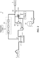
FIG. 2 is a configuration diagram of an LNG receiving facility according to an embodiment. -
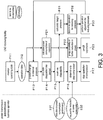
FIG. 3 is a flowchart with items to be implemented in the LNG receiving facility in association with DR. -
FIG. 1 is an illustration of an example of a relationship among participants in DR trading. A power transmission anddistribution business operator 11 includes, for example, a general power transmission and distribution business operator such as a regional electric power company. When a contract for DR is made with the power transmission anddistribution business operator 11, a reward may be given. Meanwhile, when a demand for the DR from the power transmission anddistribution business operator 11 is not complied with, payment of a penalty is required in some cases. - A
resource aggregator 12 performs supply and demand adjustment for the DR collectively for a plurality ofconsumers 13 so as to achieve distribution of a reward and reduction of a risk of payment of a penalty. Selection of theconsumer 13 which can comply with a request for the DR from the power transmission anddistribution business operator 11 and allocation of a corresponding time period may be exemplified as contents of the supply and demand adjustment. - The
consumers 13 each implements the DR in view of the supply and demand adjustment performed by theresource aggregator 12. The DR includes "up DR" for increasing electric power demand and "down DR" for reducing electric power demand. When, for example, the amount of power generation in renewable energy is large and thus electric power demand is required to be increased, a request for the "up DR" is issued. Meanwhile, when, for example, electric power demand is tight in a service area of the power transmission anddistribution business operator 11, a request for the "down DR" is issued. - A business operator of an
LNG receiving facility 2 of this example corresponds to one of theconsumers 13 among the above-mentioned participants in the DR trading. - In the example illustrated in
FIG. 1 , the power transmission anddistribution business operator 11 makes a request for the "down DR" (reduction request), which contains information about a reduction amount and a reduction time period, to theresource aggregator 12. In order to reduce power consumption so as to meet the reduction request, theresource aggregator 12 performs supply and demand adjustment for the plurality of consumers 13 (consumers A and B, and LNG receiving facility 2) in accordance with respective reducible amounts. In the example illustrated inFIG. 1 , as a result of the adjustment, it is determined that the consumer A and theLNG receiving facility 2 carry out the "down DR". Then, when the consumer A and theLNG receiving facility 2 reduce power consumption amounts, the power transmission anddistribution business operator 11 can obtain an effect of reducing an electric power load in accordance with the reduction request. - In this case, the
LNG receiving facility 2 illustrated inFIG. 1 has a function of receiving an LNG from an outside to store the LNG, vaporizing the stored LNG, and sending the vaporized LNG to ademander 3. In some cases, theLNG receiving facility 2 has a facility configuration applicable to the DR in comparison to theconsumer 13 such as a factory, which needs production adjustment for implementing the "down DR" (hereinafter referred to as "DR"). - Now, a configuration example of the
LNG receiving facility 2 of this example is described with reference toFIG. 2 . - The
LNG receiving facility 2 includes anLNG tank 21, LNG pumps 211 and 22, vaporizers (ORV 231 andSMV 232 described later), and a calorific-value adjusting unit 26. TheLNG tank 21 is configured to store the LNG. The LNG pumps 211 and 22 are configured to feed the LNG from theLNG tank 21 so as to deliver a gas to thedemander 3. The vaporizers are configured to vaporize the LNG into a state of avaporizedgas. Thecalorific-valueadjustingunit 26 is configured to add a liquefied petroleum gas (LPG) for calorific-value adjustment to the vaporized gas to obtain a product gas. - The
LNG tank 21 is a storage tank configured to store, for example, the LNG received from anLNG tanker 4 under a state of a liquid cooled to about -162 degrees Celsius. A type (such as an aboveground tank, an underground tank, or an in-ground tank) and a capacity thereof are not particularly limited. InFIG. 2 , there is illustrated an example of an aboveground tank in which an upper surface of a side wall having a cylindrical shape is covered with a dome-shaped roof. - The LNG stored in the
LNG tank 21 is fed to thevaporizers LNG pump 211 disposed in theLNG tank 21 and thefeed pump 22 for boosting pressure. - The
LNG receiving facility 2 of this example can switch, for use, between the open rack vaporizer (ORV) 231 and the submerged-combustion vaporizer (SMV) 232. TheORV 231 is a vaporizer configured to vaporize the LNG with use of seawater (S.W.), which is supplied through a seawater pump (not shown) driven by an electric motor, as a heat source. TheSMV 232 is a vaporizer configured to vaporize the LNG with use of heat of combustion of a natural gas as a heat source. In theLNG receiving facility 2, the LNG is vaporized with use of theORV 231 during normal operation, and theSMV 232 is in a standby state so as to be used for emergency operation at a time of, for example, a power failure. In theLNG receiving facility 2, for example, a plurality ofORVs 231 and a plurality ofSMVs 232 are provided. - In place of the
ORV 231, an intermediate fluid vaporizer (IFV) may be used as the vaporizer to be used for normal operation. The IFV is configured to heat an intermediate medium such as propane with use of seawater to vaporize the LNG with the intermediate medium. Also in the IFV, the seawater is supplied through a seawater pump driven by an electric motor. - The calorific-
value adjusting unit 26 is configured to mix the LPG for calorific-value adjustment with the vaporized gas so as to send a product gas having a calorific value required at thedemander 3. The LPG (butane or propane) stored in anLPG tank 25 is fed under a liquid state to the calorific-value adjusting unit 26 via anLPG pump 251. The LPG is vaporized with use of a heat medium and is mixed with the vaporized gas fed from theORV 231 to turn into a product gas in the calorific-value adjusting unit 26. The product gas, which has been subjected to calorific-value adjustment in the calorific-value adjusting unit 26, is delivered to thedemander 3. - Further, in the
LNG tank 21 that stores the LNG, a part of the LNG is vaporized due to, for example, heat input from the outside, to generate a BOG. In order to prevent an excessive increase in pressure in theLNG tank 21, aBOG compressor 24 corresponding to a gas compression unit configured to extract the BOG is connected to theLNG tank 21. TheBOG compressor 24 of this example is driven by an electric motor (not shown). - The
BOG compressor 24 is a multi-stage BOG compressor including, for example, three compression stages as illustrated inFIG. 2 . TheBOG compressor 24 is configured to boost pressure of the BOG having a pressure falling within a range of from about 12 kPaG to about 22 kPaG (suction-side pressure in a first compression stage) to a pressure falling within a range of from about 2 MPaG to about 7.5 MPaG (discharge-side pressure in a last compression stage) . The BOG boosted in pressure joins the vaporized LNG in the vaporizer (ORV 231 or SMV 232). After the calorific value is adjusted, the BOG is delivered as the product gas to thedemander 3. - In the
LNG receiving facility 2 having the configuration described above, when theBOG compressor 24 is stopped, power consumption can be reduced by about several megawatts. Stopping theBOG compressor 24 does not affect the LNG pumps 211 and 22, and the feeding of the LNG can be continued. Further, when theORV 231 is stopped, power consumption can be reduced by about several hundreds of kilowatts. In a case in which theORV 231 is stopped, the vaporization of the LNG can be continued by operating theSMV 232. - In view of the above-mentioned configuration and operation, it can be said that, in the participation in the DR trading, the
LNG receiving facility 2 corresponds to theconsumer 13 having a facility configuration applicable thereto. - Meanwhile, when the
BOG compressor 24 is stopped over a long time period and the pressure in theLNG tank 21 exceeds an upper limit value of an operating pressure, the BOG may be released, for example, toward a flare (not shown) and a loss resulting from combustion of the gas in the flare may occur. When the pressure in theLNG tank 21 further increases, a safety valve (not shown) is activated to diffuse a surplus BOG into an atmosphere. - In particular, in the
LNG receiving facility 2, the LNG is received from theLNG tanker 4 about once to about several times a month. After the reception, the amount of generation of BOG in theLNG tank 21 increases to several times, for example, about four times that during a normal operation. It is sometimes difficult to stop theBOG compressor 24 during a time period in which a large amount of BOG is generated as described above. - Thus, when a change in internal pressure of the
LNG tank 21, which may be caused in a case in which theBOG compressor 24 is stopped, is predicted to specify a stoppable time period of theBOG compressor 24, whether or not the DR can be implemented can be determined without hindering stable operation of theLNG receiving facility 2. - Now, an example of a method of calculating the stoppable time period of the
BOG compressor 24 is described. - When a stop time of the BOG compressor 24 (pressure storage start time for the BOG in the BOG compressor 24) is represented by t1 and an operation restart time of the BOG compressor 24 (pressure storage end time for the BOG) is represented by t2, a stop time period of the
BOG compressor 24 is represented by (t2-t1). - When an LNG delivery flow rate from the
LNG tank 21 is represented by F [m3/h] and a liquid level of the LNG in theLNG tank 21 at the time t1 is represented by L1 [m], a liquid level L2 [m] at the time t2 is expressed by Expression (Math. 1) (in which ID [m] represents an inner diameter of the LNG tank 21).
- Further, when a gas-phase volume of the
LNG tank 21 at the time t1 is represented by V1 [m3], a gas-phase volume V2 [m3] at the time t2 is expressed by Expression (Math. 2).
- Further, a quantity of heat input from the outside, for example, an outside air or a heater (not shown) for prevention of freezing of a ground, to the
LNG tank 21 is represented by Qtank [J/h], a quantity of heat input from theLNG pump 211 is represented by Qpump [J/h], and a quantity of heat input from other facilities is represented by Qetc [J/h], each being represented on a unit time basis, a generation amount Wbog [kg/h] of BOG per unit time in theLNG tank 21 is expressed by Expression (Math. 3) (in which λ represents evaporation latent heat [J/kg] of the LNG).
- Still further, the pressure in the
LNG tank 21 at the time t1 is represented by p1 [kPaG], the pressure in theLNG tank 21 at the time t2 is represented by p2 [kPaG], and densities of the BOG at the respective pressures are represented by ρ1 [kg/m3] and ρ2 [kg/m3], respectively. - When a temperature in the
LNG tank 21 is constant and the BOG is not extracted from theLNG tank 21, a mass balance is calculated based on the amount of BOG generated in theLNG tank 21 during the stop time period (t2-t1) and a change in volume on a gas-phase side in theLNG tank 21. As a result, Expression (Math. 4) is obtained.
- Then, when V1 and V2 are eliminated from (Math. 4) based on the relationships of (Math. 1) and (Math. 2) to rearrange (Math. 4), Expression (Math. 5) is obtained.

- The
LNG tank 21 includes a liquid level gauge. Thus, a pressure change in theLNG tank 21 in the above-mentioned time period can be obtained based only on a change in liquid level height of the LNG in theLNG tank 21 from the liquid level at the time t1 to the liquid level at the time t2. As described above, the densities ρ1 and ρ2 of the BOG are uniquely determined in accordance with the pressures p1 and p2 at the respective times . Thus, the stop time period is calculated with (Math. 5) based on the pressure change in theLNG tank 21. - Thus, the upper limit value of the operating pressure of the
LNG tank 21 is set to the pressure ρ2 in theLNG tank 21 at the time t2 (density ρ2 of the BOG at this time). As a result, the stoppable time period (t2-t1) for maintaining the pressure in theLNG tank 21 to a pressure less than the upper limit value of the operating pressure under a condition in which theBOG compressor 24 is in a stopped state can be specified. As described above, the change (L2-L1) in liquid level of the LNG during the stoppable time period can be predicted from (Math 1). - In the
LNG receiving facility 2 of this example, whether or not the DR is implemented can be determined based on the above-mentioned result of calculation of the stoppable time period of theBOG compressor 24. - Now, specific contents at the time of implementation of the DR in the
LNG receiving facility 2 are described with reference toFIG. 3 . - In the
LNG receiving facility 2, at a time of a normal operation, for example, the LNG pumps 211 and 22, the ORVs231, and theBOG compressor 24 are operated, and the product gas is sent with requested calorific value and flow rate to the demander 3 (P11) . At this time, operation data (I12: for example, the delivery flow rate F, the liquid level L1 of the LNG in theLNG tank 21, and an outside temperature and a calorific value supplied from a heater (not shown), which are to be used for calculation of the quantity of heat Qtank) that is needed for the above-mentioned calculations of the stoppable time period with (Math. 1) to (Math. 5) is continuously acquired. - Further, in the
LNG receiving facility 2, in anticipation of reception of a request for implementation of the DR (reduction in power consumption) based on, for example, a change in outside temperature or prediction of supply and demand of electric power, which may be announced by the power transmission anddistribution business operator 11, examination of reduction in power consumption can be started (examination start step). - Inthiscase, calculations of (Math. 3) and (Math. 5) are performed based on, for example, the acquired operation data and the prediction of the change in temperature (prediction of Qtank) so that a change in pressure in the
LNG tank 21 from a pressure at a time at which the implementation of the DR is anticipated is predicted (P13) . Then, the stoppable time period of theBOG compressor 24 is calculated based on the change in pressure (P14). - The above-mentioned calculations may be performed offline by an operator with use of a computer, or may be automatically performed with use of an operation control system such as a distributed control system (DCS) for the
LNG receiving facility 2. The prediction of the change in pressure in theLNG tank 21 and the calculation of the stoppable time period of theBOG compressor 24 correspond to a stoppable time period calculation step of this example. - Further, for the vaporizers, the number of
ORVs 231 and the number ofSMVs 232, which are currently operating, and consumed power of the seawater pump are calculated (P21). - When it is determined on the power transmission and
distribution business operator 11 side that the implementation of the DR is required, a preliminary notice relating to the reduction in power consumption (I01) is given from theresource aggregator 12. InFIG. 3 , illustration of theresource aggregator 12 is omitted. The notice contains information about, for example, an implementation time period of the DR (reduction time period) and demanded reduction in electric power. - When the above-mentioned preliminary notice is received, the implementation time period of the DR and the stoppable time period that has been previously calculated are compared to each other so as to examine whether or not the
BOG compressor 24 can be stopped (P15: stoppability determination step). For example, when the stoppable time period of theBOG compressor 24 is longer than the implementation time period of the DR, it is determined that the DR can be implemented. - Then, when a request for reduction in power consumption (I02) is received from the
resource aggregator 12 after the preliminary notice is made, it is determined that theBOG compressor 24 is actually stopped (P16), and an operation stop operation is executed (P17: gas compression unit stopping step). - Further, further reducible electric power is grasped based on a result of grasp of operating conditions of the
ORVs 231 and the SMVs 232 (all theORVs 231 are operating during the normal operation) (P22). Then, adjustment is performed with theresource aggregator 12 because, for example, the power consumption can be further reduced. After the adjustment, when the request for reduction in power consumption (I02) is received, the vaporizers are switched from theORVs 231 to the SMVs 232 (P23: vaporizer switching step). - Meanwhile, as a result of examination of whether or not the
BOG compressor 24 can be stopped (P15) after the reception of the preliminary notice, when it is found out that, for example, the stoppable time period of theBOG compressor 24 is shorter than the implementation time period of the DR, it is determined that the stoppable time period that meets the request from theresource aggregator 12 cannot be ensured. - In this case, when there is plenty of time from the reception of the preliminary notice to the reception of the actual request for reduction in power consumption, operation adjustment for reducing the pressure in the
LNG tank 21 may be performed. As contents of the operation adjustment, the following is exemplified. Specifically, a mixing ratio of the BOG to the product gas is increased to increase the amount of extraction of the BOG from theLNG tank 21. Thedemander 3 is requested to increase the amount of reception of the product gas to thereby increase the amount of feeding of the LNG so as to lower the liquid level of the LNG. - Thus, when it is determined in the stage of examination of stoppability (P15) that it is difficult to stop the
BOG compressor 24, a target pressure at a time of implementation of the operation adjustment is calculated so as to be lower than the pressure in theLNG tank 21 at the time when the determination is made (P31: target pressure setting step). The target pressure is set so that the stoppable time period of theBOG compressor 24, which is calculated by the above-mentioned method, becomes longer than the implementation time period of the DR. - After that, when it is determined that the operation adjustment for reducing the internal pressure of the
LNG tank 21 to the target pressure can be implemented (P32), the operation adjustment is performed (P33: pressure reduction step). Then, the prediction of a change in internal pressure of the LNG tank 21 (P13) and the calculation of the stoppable time period of the BOG compressor 24 (P14) are performed, and the examination of the stoppability (P15) is performed again. When the internal pressure of theLNG tank 21 reaches the target pressure due to the operation adjustment, it is determined that theBOG compressor 24 can be stopped under this state. Thus, after the request for the reduction in power consumption (I02) is received from theresource aggregator 12, it is determined that theBOG compressor 24 is stopped (P16). Then, the operation stop operation is performed (P17). - Meanwhile, as described above, when an LNG reception time period from the
LNG tanker 4, in which the amount of generation of the BOG becomes several times that during the normal operation, and the implementation time period of the DR overlap, there is a high possibility that theBOG compressor 24 cannot be stopped even after the above-mentioned operation adjustment is performed. Thus, in this case, the examination of whether or not theBOG compressor 24 can be stopped may be omitted, and determination of prioritization of continuation of the operation of the BOG compressor 24 (continuation determination step) may be performed. - The overlap between the reception time period for the LNG and the implementation time period of the DR may be avoided by adjusting a ship allocation schedule of the
LNG tanker 4 so that the LNG is received on Saturday, Sunday, or a holiday on which there is a low possibility that the request for the implementation of the DR may be issued. - According to the method of operating the
LNG receiving facility 2 according to this embodiment, the following effects are obtained. The stoppable time period of theBOG compressor 24, in which the BOG is extracted from theLNG tank 21, is calculated, and whether or not theBOG compressor 24 can be stopped is determined based on the result of calculation. Thus, the DR can be implemented without hindering the stable operation of theLNG receiving facility 2. - In the example described with reference to
FIG. 3 , in anticipation of the implementation of the DR, the prediction of a change in internal pressure of the LNG tank 21 (P13) and the calculation of the stoppable time period of the BOG compressor 24 (P14) are performed in advance. Then, in response to the preliminary notice of the implementation of the DR, whether or not theBOG compressor 24 can be stopped is examined. - However, the order of examination may be suitably changed. For example, when there is sufficient time from the reception of the request for the reduction in power consumption (102) to the execution of the request (stop of the BOG compressor 24), the prediction of a change in internal pressure of the
LNG tank 21 and the calculation of the stoppable time period of the BOG compressor 24 (P13 and P14: stoppable time period calculation step), and the examination of stoppability (P15: stoppability determination step) may be performed after the request for the reduction is received. -
- 11
- power transmission and distribution business operator
- 12
- resource aggregator
- 13
- consumer
- 2
- LNG receiving facility
- 21
- LNG tank
- 211, 22
- LNG pump
- 231
- open rack vaporizer (ORV)
- 232
- submerged-combustion vaporizer (SMV)
- 24
- BOG compressor
- 3
- demander
Claims (8)
- A method of operating a liquefied natural gas receiving facility,
the liquefied natural gas receiving facility including:a storage tank configured to store a liquefied natural gas received from an outside;vaporizers configured to vaporize the liquefied natural gas delivered from the storage tank so as to send the liquefied natural gas in a gaseous state; anda gas compression unit to be driven by an electric motor, which is configured to boost pressure of a boil off gas generated in the storage tank so as to mix the boil off gas boosted in pressure with the natural gas vaporized in the vaporizers,the method comprising:an examination start step of starting examination of reduction in power consumption upon receiving a request for the reduction in power consumption, which contains information about a reduction time period, or in anticipation of reception of the request;a stoppable time period calculation step of predicting a change in internal pressure of the storage tank, which is caused when the gas compression unit is stopped, and calculating a stoppable time period of the gas compression unit; anda stoppability determination step of determining whether the gas compression unit is stoppable based on a result of comparison between the reduction time period and the stoppable time period of the gas compression unit. - The method of operating a liquefied natural gas receiving facility according to claim 1, further comprising a gas compression unit stopping step of, when determination is made in the stoppability determination step that the gas compression unit is stoppable in the reduction time period, stopping the gas compression unit.
- The method of operating a liquefied natural gas receiving facility according to claim 2,
wherein the vaporizers include:a vaporizer for normal operation, which is configured to vaporize the liquefied natural gas with use of seawater supplied as a heat source through a seawater pump to be driven by an electric motor; anda vaporizer for emergency operation, which is configured to vaporize the liquefied natural gas with use of heat of combustion of the natural gas as a heat source, andwherein the method further comprises a vaporizer switching step to be executed in addition to execution of the gas compression unit stopping step, the vaporizer switching step of switching the vaporizer for normal operation to the vaporizer for emergency operation and vaporizing the liquefied natural gas. - The method of operating a liquefied natural gas receiving facility according to claim 1, wherein, in the stoppable time period calculation step, the change in internal pressure is predicted based on a change in gas-phase volume, which is caused along with the delivery of the liquefied natural gas from the storage tank, and a boil off gas amount generated in the storage tank.
- The method of operating a liquefied natural gas receiving facility according to claim 4, wherein the boil off gas amount generated in the storage tank is calculated based on a quantity of heat input to the storage tank.
- The method of operating a liquefied natural gas receiving facility according to claim 1, wherein, in the stoppable time period calculation step, a time period in which a prediction value of the change in internal pressure of the storage tank is less than an upper limit value of an operating pressure, which is set for the storage tank, is set as the stoppable time period.
- The method of operating a liquefied natural gas receiving facility according to claim 1, further comprising a continuation determination step of, when the reduction time period overlaps a time period in which the liquefied natural gas is received by the storage tank from the outside, determining prioritization of continuation of the operation of the gas compression unit.
- The method of operating a liquefied natural gas receiving facility according to claim 1, further comprising:a target pressure setting step of, when a result of determination in the stoppability determination step is negative, setting a target pressure lower than a pressure in the storage tank at a time of execution of the stoppability determination step so as to reduce power consumption; anda pressure reduction step of reducing the internal pressure of the storage tank to the target pressure,wherein the stoppability determination step is executed again after the pressure reduction step.
Applications Claiming Priority (1)
| Application Number | Priority Date | Filing Date | Title |
|---|---|---|---|
| PCT/JP2018/034255 WO2020054068A1 (en) | 2018-09-14 | 2018-09-14 | Method for operating liquefied natural gas receiving equipment |
Publications (2)
| Publication Number | Publication Date |
|---|---|
| EP3851730A1 true EP3851730A1 (en) | 2021-07-21 |
| EP3851730A4 EP3851730A4 (en) | 2021-09-22 |
Family
ID=66166629
Family Applications (1)
| Application Number | Title | Priority Date | Filing Date |
|---|---|---|---|
| EP18933604.3A Withdrawn EP3851730A4 (en) | 2018-09-14 | 2018-09-14 | Method for operating liquefied natural gas receiving equipment |
Country Status (4)
| Country | Link |
|---|---|
| EP (1) | EP3851730A4 (en) |
| JP (1) | JP6503521B1 (en) |
| KR (1) | KR20210058819A (en) |
| WO (1) | WO2020054068A1 (en) |
Families Citing this family (3)
| Publication number | Priority date | Publication date | Assignee | Title |
|---|---|---|---|---|
| EP4322312A4 (en) | 2021-05-06 | 2025-03-05 | LG Energy Solution, Ltd. | BUSBAR ARRANGEMENT, BATTERY PACK THEREFORE AND AUTOMOTIVE |
| JP2024080937A (en) * | 2022-12-05 | 2024-06-17 | 三菱造船株式会社 | Method for predicting the state of liquefied gas in a tank, and system for predicting the state of liquefied gas in a tank |
| CN119668311B (en) * | 2023-09-19 | 2026-02-13 | 中国石油天然气股份有限公司 | An automatic control method and system for recondenser liquid level in a liquefied natural gas receiving terminal |
Family Cites Families (10)
| Publication number | Priority date | Publication date | Assignee | Title |
|---|---|---|---|---|
| JPS55143921A (en) | 1979-04-26 | 1980-11-10 | Mitsui Toatsu Chem Inc | Preparation of alkylphenol |
| JP5302661B2 (en) * | 2008-12-24 | 2013-10-02 | 三菱重工業株式会社 | Insufficient power supply system for in-house power generation facilities during operation |
| JP5427458B2 (en) * | 2009-04-08 | 2014-02-26 | 株式会社Nttファシリティーズ | Power supply control device, power supply control method, and power supply system |
| WO2014080445A1 (en) * | 2012-11-26 | 2014-05-30 | 中国電力株式会社 | Bog processing apparatus and bog processing method |
| JP5959782B2 (en) * | 2014-02-28 | 2016-08-02 | 日揮株式会社 | Facility for receiving liquefied natural gas |
| EP3240140A4 (en) * | 2014-12-25 | 2018-05-23 | Kyocera Corporation | Server, user terminal, and program |
| JP6368671B2 (en) * | 2015-03-19 | 2018-08-01 | 株式会社日立製作所 | Power generation facility management apparatus and power generation facility management method |
| JP6610059B2 (en) * | 2015-07-29 | 2019-11-27 | 富士電機株式会社 | Electric power demand induction device |
| JP6770898B2 (en) * | 2017-01-10 | 2020-10-21 | 株式会社Ihiプラント | BOG compressor load control device for LNG storage facility |
| JP6343372B1 (en) * | 2017-06-09 | 2018-06-13 | 九電みらいエナジー株式会社 | Demand response system |
-
2018
- 2018-09-14 JP JP2018560924A patent/JP6503521B1/en not_active Expired - Fee Related
- 2018-09-14 EP EP18933604.3A patent/EP3851730A4/en not_active Withdrawn
- 2018-09-14 KR KR1020217005583A patent/KR20210058819A/en not_active Abandoned
- 2018-09-14 WO PCT/JP2018/034255 patent/WO2020054068A1/en not_active Ceased
Also Published As
| Publication number | Publication date |
|---|---|
| EP3851730A4 (en) | 2021-09-22 |
| WO2020054068A1 (en) | 2020-03-19 |
| KR20210058819A (en) | 2021-05-24 |
| JPWO2020054068A1 (en) | 2020-10-22 |
| JP6503521B1 (en) | 2019-04-17 |
Similar Documents
| Publication | Publication Date | Title |
|---|---|---|
| EP2932148B1 (en) | Method of starting gas delivery from a liquefied gas fuel system to a gas operated engine | |
| CN103314208B (en) | Fuel supply system is unified and is operated the method for fuel supply system | |
| EP2932147B1 (en) | Method of filling a fuel tank with liquefied gas and liquefied gas fuel system | |
| JP5190315B2 (en) | Low temperature liquid gas supply equipment | |
| KR102438790B1 (en) | bunkering vessel | |
| PL208380B1 (en) | Gas supply arrangement of a marine vessel and method of providing gas in a gas supply arrangement of a marine vessel | |
| US9534736B2 (en) | Device for supplying gas | |
| DK201970036A1 (en) | Large-scale hydrogen refueling station | |
| KR102460504B1 (en) | liquefied gas tank, fuel gas supply system, and ship having the same | |
| JP5959782B2 (en) | Facility for receiving liquefied natural gas | |
| KR20170077558A (en) | A Treatment System of Liquefied Gas | |
| EP3542045B1 (en) | A liquefied gas fuel feeding system and a method of operating a power plant of internal combustion engines powered with liquefied gas | |
| WO2010151118A1 (en) | System and method for the delivery of lng | |
| JP6503521B1 (en) | Operation method of liquefied natural gas receiving facility | |
| JP5959778B2 (en) | Facility for receiving liquefied natural gas | |
| JP6770898B2 (en) | BOG compressor load control device for LNG storage facility | |
| KR20150092771A (en) | A Treatment System Of Liquefied Gas | |
| KR20180134611A (en) | Gas Treatment System and Vessel having the same | |
| KR20180011633A (en) | Gas Treatment System and Vessel having same | |
| EP3839321A1 (en) | Installation for compensating fluctuations in gas demand in natural gas networks and the method of implementing this compensation | |
| KR102321086B1 (en) | Fuel supply system for ship | |
| RU2858105C1 (en) | Autonomous two-sided station for refuelling vehicles with compressed natural gas | |
| WO2016102638A1 (en) | Method and system for conditioning of lng | |
| EP4283183A1 (en) | Gas delivery system | |
| Hermeling | LNG Applications |
Legal Events
| Date | Code | Title | Description |
|---|---|---|---|
| STAA | Information on the status of an ep patent application or granted ep patent |
Free format text: STATUS: THE INTERNATIONAL PUBLICATION HAS BEEN MADE |
|
| PUAI | Public reference made under article 153(3) epc to a published international application that has entered the european phase |
Free format text: ORIGINAL CODE: 0009012 |
|
| STAA | Information on the status of an ep patent application or granted ep patent |
Free format text: STATUS: REQUEST FOR EXAMINATION WAS MADE |
|
| 17P | Request for examination filed |
Effective date: 20210223 |
|
| AK | Designated contracting states |
Kind code of ref document: A1 Designated state(s): AL AT BE BG CH CY CZ DE DK EE ES FI FR GB GR HR HU IE IS IT LI LT LU LV MC MK MT NL NO PL PT RO RS SE SI SK SM TR |
|
| A4 | Supplementary search report drawn up and despatched |
Effective date: 20210825 |
|
| RIC1 | Information provided on ipc code assigned before grant |
Ipc: F17C 9/02 20060101ALI20210819BHEP Ipc: F17C 13/00 20060101AFI20210819BHEP |
|
| DAV | Request for validation of the european patent (deleted) | ||
| DAX | Request for extension of the european patent (deleted) | ||
| STAA | Information on the status of an ep patent application or granted ep patent |
Free format text: STATUS: THE APPLICATION IS DEEMED TO BE WITHDRAWN |
|
| 18D | Application deemed to be withdrawn |
Effective date: 20220325 |