EP3851729A1 - Optischer sensor und ein verfahren zur erfassung von objekten mittels eines optischen sensors - Google Patents
Optischer sensor und ein verfahren zur erfassung von objekten mittels eines optischen sensors Download PDFInfo
- Publication number
- EP3851729A1 EP3851729A1 EP20152239.8A EP20152239A EP3851729A1 EP 3851729 A1 EP3851729 A1 EP 3851729A1 EP 20152239 A EP20152239 A EP 20152239A EP 3851729 A1 EP3851729 A1 EP 3851729A1
- Authority
- EP
- European Patent Office
- Prior art keywords
- optical sensor
- protective field
- permissible
- residual
- generated
- Prior art date
- Legal status (The legal status is an assumption and is not a legal conclusion. Google has not performed a legal analysis and makes no representation as to the accuracy of the status listed.)
- Granted
Links
Images


Classifications
-
- F—MECHANICAL ENGINEERING; LIGHTING; HEATING; WEAPONS; BLASTING
- F16—ENGINEERING ELEMENTS AND UNITS; GENERAL MEASURES FOR PRODUCING AND MAINTAINING EFFECTIVE FUNCTIONING OF MACHINES OR INSTALLATIONS; THERMAL INSULATION IN GENERAL
- F16P—SAFETY DEVICES IN GENERAL; SAFETY DEVICES FOR PRESSES
- F16P3/00—Safety devices acting in conjunction with the control or operation of a machine; Control arrangements requiring the simultaneous use of two or more parts of the body
- F16P3/12—Safety devices acting in conjunction with the control or operation of a machine; Control arrangements requiring the simultaneous use of two or more parts of the body with means, e.g. feelers, which in case of the presence of a body part of a person in or near the danger zone influence the control or operation of the machine
- F16P3/14—Safety devices acting in conjunction with the control or operation of a machine; Control arrangements requiring the simultaneous use of two or more parts of the body with means, e.g. feelers, which in case of the presence of a body part of a person in or near the danger zone influence the control or operation of the machine the means being photocells or other devices sensitive without mechanical contact
- F16P3/144—Safety devices acting in conjunction with the control or operation of a machine; Control arrangements requiring the simultaneous use of two or more parts of the body with means, e.g. feelers, which in case of the presence of a body part of a person in or near the danger zone influence the control or operation of the machine the means being photocells or other devices sensitive without mechanical contact using light grids
-
- F—MECHANICAL ENGINEERING; LIGHTING; HEATING; WEAPONS; BLASTING
- F16—ENGINEERING ELEMENTS AND UNITS; GENERAL MEASURES FOR PRODUCING AND MAINTAINING EFFECTIVE FUNCTIONING OF MACHINES OR INSTALLATIONS; THERMAL INSULATION IN GENERAL
- F16P—SAFETY DEVICES IN GENERAL; SAFETY DEVICES FOR PRESSES
- F16P3/00—Safety devices acting in conjunction with the control or operation of a machine; Control arrangements requiring the simultaneous use of two or more parts of the body
- F16P3/12—Safety devices acting in conjunction with the control or operation of a machine; Control arrangements requiring the simultaneous use of two or more parts of the body with means, e.g. feelers, which in case of the presence of a body part of a person in or near the danger zone influence the control or operation of the machine
- F16P3/14—Safety devices acting in conjunction with the control or operation of a machine; Control arrangements requiring the simultaneous use of two or more parts of the body with means, e.g. feelers, which in case of the presence of a body part of a person in or near the danger zone influence the control or operation of the machine the means being photocells or other devices sensitive without mechanical contact
- F16P3/142—Safety devices acting in conjunction with the control or operation of a machine; Control arrangements requiring the simultaneous use of two or more parts of the body with means, e.g. feelers, which in case of the presence of a body part of a person in or near the danger zone influence the control or operation of the machine the means being photocells or other devices sensitive without mechanical contact using image capturing devices
-
- G—PHYSICS
- G01—MEASURING; TESTING
- G01S—RADIO DIRECTION-FINDING; RADIO NAVIGATION; DETERMINING DISTANCE OR VELOCITY BY USE OF RADIO WAVES; LOCATING OR PRESENCE-DETECTING BY USE OF THE REFLECTION OR RERADIATION OF RADIO WAVES; ANALOGOUS ARRANGEMENTS USING OTHER WAVES
- G01S17/00—Systems using the reflection or reradiation of electromagnetic waves other than radio waves, e.g. lidar systems
- G01S17/02—Systems using the reflection of electromagnetic waves other than radio waves
- G01S17/06—Systems determining position data of a target
- G01S17/42—Simultaneous measurement of distance and other co-ordinates
-
- G—PHYSICS
- G01—MEASURING; TESTING
- G01S—RADIO DIRECTION-FINDING; RADIO NAVIGATION; DETERMINING DISTANCE OR VELOCITY BY USE OF RADIO WAVES; LOCATING OR PRESENCE-DETECTING BY USE OF THE REFLECTION OR RERADIATION OF RADIO WAVES; ANALOGOUS ARRANGEMENTS USING OTHER WAVES
- G01S17/00—Systems using the reflection or reradiation of electromagnetic waves other than radio waves, e.g. lidar systems
- G01S17/88—Lidar systems specially adapted for specific applications
- G01S17/93—Lidar systems specially adapted for specific applications for anti-collision purposes
- G01S17/931—Lidar systems specially adapted for specific applications for anti-collision purposes of land vehicles
Definitions
- the invention relates to an optical sensor and a method for detecting objects by means of an optical sensor.
- optical sensors are typically used in the field of security technology for monitoring danger areas.
- a protective field is defined and stored in the evaluation unit of the optical sensor according to the size of the danger area.
- the monitoring function of the optical sensor is then such that it is used to check whether a dangerous, i.e. impermissible, object penetrates the protective field. If this is the case, the optical sensor is used to generate an object detection signal that can be used to initiate a security measure.
- the optical sensor can in particular be mounted on a movable unit such as a vehicle.
- the vehicle can be designed as a driverless transport system, for example.
- the optical sensor is mounted on the front so that the area in front of the vehicle is monitored with the protective field. If an object penetrates the protective field and an object detection signal is generated in the optical sensor as a result, the vehicle is braked or stopped as a safety measure.
- a definition of only one fixed, predetermined protective field is not suitable for achieving a complete, permanent monitoring function.
- the optical sensor then triggers by generating a Object detection signal from a standstill of the vehicle, although there is no hazardous situation.
- an optical sensor with a sensor unit generating sensor signals and an evaluation unit in which the sensor signals are evaluated is known.
- a protective field which is within the detection area and is delimited by a protective field boundary, is specified in the evaluation unit.
- An object detection signal is generated in the evaluation unit when the penetration of an impermissible object into the protective field is registered on the basis of the sensor signals.
- this part of the protective field boundary is replaced by the contour of the permissible object structure over part of the protective field boundary in the protective field by means of the sensor unit in the evaluation unit.
- the invention is based on the object of improving the functionality of an optical sensor and a method of the type mentioned at the beginning.
- the invention relates to an optical sensor for detecting objects in a detection area, a protective field being specified in the optical sensor.
- an object detection signal is generated in the optical sensor.
- a residual protective field is generated within the protective field.
- an object detection signal is only generated in the optical sensor if this object intervention represents a deviation from a permissible object structure.
- the invention also relates to a method for detecting objects by means of an optical sensor.
- An essential advantage of the invention is that the optical sensor can be used to reliably detect objects in danger areas, so that it can be used in particular as a safety sensor in safety-related applications.
- the optical sensor distinguishes between permissible and non-permissible objects.
- Inadmissible objects such as people represent a hazard, so that when an inadmissible object is detected, the optical sensor generates an object detection signal that triggers a safety function, such as the shutdown of a machine, system or vehicle that is connected to the optical sensor can be monitored.
- a safety function such as the shutdown of a machine, system or vehicle that is connected to the optical sensor can be monitored.
- the detection of permissible objects advantageously does not lead to the generation of an object detection signal and thus does not trigger the safety function, so that unnecessary downtimes of the machine, the system or the vehicle are avoided.
- a residual protective field is defined within the protective field, in which only object monitoring initially takes place.
- permissible objects moving relative to the optical sensor can also be recognized as such at high speed, so that they do not lead to the generation of an object detection signal and unnecessary triggering of the safety function.
- the residual protective field can be defined completely independently of the relative speed of the detected permissible objects to the optical sensor.
- the check for illegal objects within the Residual protective field are present, can take place immediately with the generation of the residual protective field, whereby this object detection is also independent of the speed.
- the object can be detected with very short reaction times, without the need for additional sensors to determine the speed.
- Another essential aspect of the invention is that within the residual protective field an evaluation for object detection that differs from the object detection within the protective field takes place.
- the object detection within the protective field takes place in such a way that the object detection signal is generated every time an object encroaches on the protective field. This evaluation can be done very quickly and easily.
- the object detection within the residual protective field is generally different from this, since the definition of this residual protective field is already dependent on the detection of permitted objects.
- a permissible object contour detected by this advantageously forms a boundary of the residual protective field.
- the detection of the permissible object contour and the dependent formation of the residual protective field are time-dependent.
- the residual protective field is quickly adapted to permitted objects, which are also moving at high speed relative to the optical sensor move. With this formation of the residual protective field, these permissible objects can be masked out so that they do not lead to an unnecessary generation of an object detection signal.
- the residual protective field is preferably dimensioned in such a way that the residual protective field forms a partial area of the protective field.
- the residual protective field is an angular segment within the protective field.
- the residual protection field is thus adapted to the dimensions of the permitted objects detected.
- the functionality of the optical sensor according to the invention can be expanded in that several protective fields and / or several residual protective fields are provided.
- the reliability of the detection of permissible objects results not only from a dimensioning of the residual protective field that is adapted to this. Rather, there is also a check for object interventions in the residual protection field to determine whether a permissible object structure is present, so that an object detection signal is generated only in the event that the evaluation in the optical sensor shows that the object intervention is not caused by a permissible object structure.
- Setpoint values characterizing permissible object structures are particularly advantageously stored in the optical sensor and are compared as actual values with measured values determined by the optical sensor.
- permissible object structures are formed by features or contours of permissible objects.
- the optical sensor is mounted on a vehicle
- the permitted objects are made up of stationary obstacles such as the walls of a factory hall or machines installed there.
- contours of permitted objects can be entered into the optical sensor via an input unit such as a graphical user interface and stored there as setpoint values.
- contours of permitted objects can be specified in the form of straight lines or curves.
- permissible objects are recognized by comparing the measured values of the optical sensor as actual values with the stored nominal values.
- the measured values are generally generated cyclically in measuring cycles.
- the measured values of a measuring cycle are compared directly as the actual value with the setpoint values, which means that permissible objects can be detected very quickly.
- measured values are determined in several measuring cycles and then averaged, with the averaged measured values forming the actual values.
- Averaging largely eliminates the effects of noise on the measured values, so that a very safe and reliable detection of permissible objects is made possible.
- the optical sensor is particularly advantageously a distance sensor, so that it is possible to determine the position of objects in the protective field or residual protective field.
- the optical sensor is a camera sensor or a laser scanner.
- the position of objects can be determined in two-dimensional or spatial areas.
- FIG. 1a shows a first exemplary embodiment of the optical sensor 1 according to the invention.
- the optical sensor 1 is designed as a surface distance sensor, this having as a sensor unit a distance sensor with a transmitter 3 emitting light beams 2 and a receiver 4 receiving light beams 2.
- the transmitter 3 is designed in the form of a laser diode.
- a distance measurement is preferably carried out according to a pulse time-of-flight method or according to a phase measurement method.
- the transmitter 3 emits light beams 2 in the form of light pulses.
- the transmitter 3 emits light beams 2 on which a modulation is impressed.
- the evaluation of the sensor signals of the distance sensor is evaluated in an evaluation unit 5.
- the evaluation unit 5 has a redundant structure, for example in the form of two computer units that monitor each other cyclically.
- the light beams 2 of the transmitter 3 are periodically guided into a flat detection area.
- the transmitter 3 and the receiver 4 are accommodated in a rotating measuring head 6, the side wall of which has an exit window for the light beams 2.
- the measuring head 6 is mounted on a stationary base 8 with a rotary bearing 7.
- the measuring head 6 is rotated about an axis of rotation D which coincides with the axis of symmetry of the measuring head 6 by a drive (not shown).
- the light beams 2 periodically sweep over a plane which is oriented perpendicular to the axis of rotation D and which forms the detection area.
- the detection area can also only encompass a partial area of a full rotation of 360 °.
- the transmitter 3 and the receiver 4 are connected to the evaluation unit 5 in the rotary bearing 7 via feed lines which may operate in a contactless manner.
- the transit time of the light beams 2 from the transmitter 3 to the object 9 and back to the receiver 4 is determined, from which the object distance is determined.
- the current rotational position of the measuring head 6 is recorded. The position of the object 9 within the detection area can thus be determined.
- Figure 1b shows a variant of the embodiment according to Figure 1a of the optical sensor 1 according to the invention.
- the optical sensor 1 is in turn designed as a surface distance sensor, which corresponds to the embodiment according to FIG Figure 1a has a distance sensor with a transmitter 3 and receiver 4 and an evaluation unit 5.
- the optical sensor 1 according to Figure 1b differs from the optical sensor 1 according to Figure 1a only with regard to the beam deflection of the light beams 2.
- the transmitter 3 and the receiver 4 as well as the evaluation unit 5 are arranged stationary in a housing 10, with an exit window, not shown separately, being provided in the side wall of the housing 10 through which the light beams 2 are guided.
- a motor-driven deflection unit 11 is provided in the housing 10, which has a deflection mirror 12 which can be rotated about a perpendicular axis of rotation D.
- the light beams 2 emitted by the transmitter 3 are thus deflected in a plane which forms the detection area and runs perpendicular to the axis of rotation D.
- the light beams 2 reflected back by the object 9 run coaxially to the light beams 2 emitted by the transmitter 3.
- the coaxial beam path is achieved by means of a beam splitter mirror 13.
- the detection area can be limited to an angular range of less than 360 °.
- Figure 2 shows a third example of an optical sensor 1 in the form of a camera sensor.
- the transmitter 3 emits the light beams 2 in a fixed direction, the so-called field of view (FOV).
- the receiver 4 is in shape a camera, in particular a CCD array or CMOS array.
- a distance measurement is carried out for all receiving elements of the camera according to a pulse time-of-flight method or a phase measurement method.
- a 3D camera sensor is thereby obtained.
- the camera sensor can also be designed as a stereoscopic camera system.
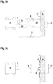
- Figures 3a , 3b, 3c show, in the first exemplary embodiment, monitoring with the optical sensor 1 according to the invention.
- the optical sensor 1 is mounted on the front of a vehicle 14, for example an AGV (driverless transport system). With the optical sensor 1 is how Figure 3a shows, a protective field 15 is monitored in front of the vehicle, which has a length L and width B. How out Figure 3a As can be seen, the vehicle 14 is moving towards a wall 16 which forms an allowable object. A reflector 17, the width of which corresponds approximately to the width B of the protective field 15, is fastened to the surface of the wall 16. When arranging Figure 3a the vehicle 14 is still at a great distance from the wall 16, which consequently lies outside the protective field 15.
- AGV driverless transport system
- an object detection signal is then generated, which triggers a safety function which, in the present case, is formed by an emergency stop of the vehicle 14.
- the vehicle 14 must therefore drive up to the wall 16, for example, in order to carry out unloading or loading processes there. To this end, it is necessary that the detection of the wall 16 within the protective field 15 does not trigger an emergency stop of the vehicle 14 prematurely.
- Figure 3b shows the situation when the vehicle 14 has approached the wall 16 so far that the wall 16 enters the original protective field 15 (in Figure 3b drawn in dashed lines) protrudes.
- the wall 16 is recognized by detecting the contour of the reflector 17 by means of the optical sensor 1.
- the contour of the reflector 17 can be determined in a learning process.
- the contour is stored as a parameter value in the evaluation unit 5.
- this contour is a straight line.
- the vehicle 14 moves quickly towards the wall 16 and the optical sensor 1 is used as a scanner ( Figure 1 and 2 )
- the vehicle 14 moves significantly towards the wall 16 within a scan between the time at which the left and right edges are detected, so that the contour of the reflector 17 is designed as a curved curve.
- the reflector 17 While driving towards the wall 16, the reflector 17 is in the area B '( Figure 3c ) detected by the optical sensor 1 and the measured values obtained (measuring contour M in Figure 3c ) are compared with the setpoint values of the stored contour of the reflector 17.
- the reflector 17 and thus the wall 16 are recognized as a permissible object.
- a residual protective field 18 within the remaining protective field 15 is then generated in the optical sensor 1 as a function of the detection of the reflector 17.
- the remaining protective field 18 extends to the wall 16, the length of which is L ' ⁇ L.
- the remaining protective field 18 has the reflector 17 as a border and forms an angular segment emanating from the optical sensor 1.
- the remaining protective field 15 'extends on both sides of this residual protective field 18.
- the residual protective field 18 can be designed to be rectangular and replace the protective field 15 '.
- the further evaluation in the optical sensor 1 then takes place in such a way that every object intervention in the protective field 15 ′ leads to the generation of the object detection signal.
- the evaluation takes place in such a way that it is checked whether only the permissible object structure of the reflector 17, that is to say the wall 16, is registered. If this is the case, no object detection signal is generated and no safety function is triggered and the vehicle 14 can move closer to the wall 16. However, if an impermissible object structure is detected, for example a person in front of the wall 16, the optical sensor 1 generates the object detection signal and the vehicle 14 is stopped.
- the remaining protective field 18 and also the remaining protective field 15 ′ are continuously adapted to the changing position of the wall 16.
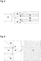
- Figure 4 shows a further example of a monitoring carried out with the optical sensor 1.
- the optical sensor 1 is again located on the front of a vehicle 14 '.
- the vehicle 14 ′ drives towards a narrow aisle between two walls 16.
- reflectors 17 are again attached, by means of which these are recognized as permissible objects.
- the angular segments delimited by the reflectors 17 form residual protective fields 18. This is followed by several protective fields 15 '.
- Figure 5 shows a further example of a monitoring carried out with the optical sensor 1.
- the optical sensor 1 is arranged on the front side of a stationary machine 19.
- the permitted object is formed by a vehicle 14 ′ that is moving towards the machine 19.
- a reflector 17 by means of which the vehicle 14 'is recognized as a permissible object.
- a residual protective field 18 is again defined as a function of this.
Landscapes
- Engineering & Computer Science (AREA)
- General Engineering & Computer Science (AREA)
- Physics & Mathematics (AREA)
- Mechanical Engineering (AREA)
- Electromagnetism (AREA)
- Computer Networks & Wireless Communication (AREA)
- General Physics & Mathematics (AREA)
- Radar, Positioning & Navigation (AREA)
- Remote Sensing (AREA)
- Optical Radar Systems And Details Thereof (AREA)
- Length Measuring Devices By Optical Means (AREA)
Abstract
Description
- Die Erfindung betrifft einen optischen Sensor und ein Verfahren zur Erfassung von Objekten mittels eines optischen Sensors.
- Derartige optische Sensoren werden typischerweise im Bereich der Sicherheitstechnik zur Gefahrenbereichsüberwachung eingesetzt. Dabei wird in der Auswerteeinheit des optischen Sensors entsprechend der Größe des Gefahrenbereichs ein Schutzfeld definiert und abgespeichert. Die Überwachungsfunktion des optischen Sensors ist dann derart, dass mit diesem kontrolliert wird, ob ein gefahrbringendes, das heißt unzulässiges Objekt in das Schutzfeld eindringt. Ist dies der Fall, wird mit dem optischen Sensor ein Objektfeststellungssignal generiert, das zur Einleitung einer Sicherheitsmaßnahme verwendet werden kann.
- Der optische Sensor kann insbesondere an einer beweglichen Einheit wie einem Fahrzeug montiert sein. Das Fahrzeug kann beispielsweise als fahrerloses Transportsystem ausgebildet sein. In dem Fall ist der optische Sensor an der Frontseite montiert, sodass mit dem Schutzfeld das Vorfeld des Fahrzeugs überwacht wird. Dringt ein Objekt in das Schutzfeld ein und wird dadurch ein Objektfeststellungssignal im optischen Sensor generiert, so wird dadurch als Sicherheitsmaßnahme das Fahrzeug abgebremst oder angehalten.
- Problematisch ist insbesondere im letzteren Fall, dass eine Definition nur eines fest vorgegebenen Schutzfelds zur Erzielung einer vollständigen, dauerhaften Überwachungsfunktion nicht geeignet ist. Wenn beispielsweise das Fahrzeug in einer Kurve fährt, sodass eine an sich unkritische Umgebungskontur in das Schutzfeld ragt. Der optische Sensor löst dann durch die Generierung eines Objektfeststellungssignals einen Stillstand des Fahrzeugs aus, obwohl keine Gefährdungssituation vorliegt.
- Aus der
EP 3 330 740 A1 ist ein optischer Sensor mit einer Sensorsignale generierenden Sensoreinheit und eine Auswerteeinheit, in welcher die Sensorsignale ausgewertet werden, bekannt. In der Auswerteeinheit ist ein innerhalb des Erfassungsbereichs liegendes, von einer Schutzfeldgrenze begrenztes Schutzfeld vorgegeben. In der Auswerteeinheit wird ein Objektfeststellungssignal generiert, wenn anhand der Sensorsignale ein Eindringen eines unzulässigen Objekts in das Schutzfeld registriert wird. Bei Erfassen des Eindringens einer zulässigen Objektstruktur wird über einen Teil der Schutzfeldgrenze in das Schutzfeld mittels der Sensoreinheit in der Auswerteeinheit dieser Teil der Schutzfeldgrenze durch die Kontur der zulässigen Objektstruktur ersetzt. - Der Erfindung liegt die Aufgabe zugrunde die Funktionalität eines optischen Sensors und eines Verfahrens der eingangs genannten Art zu verbessern.
- Zur Lösung dieser Aufgabe sind die Merkmale der unabhängigen Ansprüche vorgesehen. Vorteilhafte Ausführungsformen und zweckmäßige Weiterbildungen der Erfindung sind in den abhängigen Ansprüchen beschrieben.
- Die Erfindung betrifft einen optischen Sensor zur Erfassung von Objekten in einem Erfassungsbereich, wobei in dem optischen Sensor ein Schutzfeld vorgegeben ist. Bei Erfassen eines Objekteingriffs im Schutzfeld wird in dem optischen Sensor ein Objektfeststellungssignal generiert. Im optischen Sensor wird abhängig von der Erfassung eines zulässigen Objekts ein Restschutzfeld innerhalb des Schutzfeldes generiert. Bei einem Objekteingriff im Restschutzfeld wird im optischen Sensor nur dann ein Objektfeststellungssignal generiert, wenn dieser Objekteingriff eine Abweichung von einer zulässigen Objektstruktur darstellt.
- Die Erfindung betrifft weiterhin ein Verfahren zur Erfassung von Objekten mittels eines optischen Sensors.
- Ein wesentlicher Vorteil der Erfindung besteht darin, dass mit dem optischen Sensor eine sichere Objektdetektion in Gefahrenbereichen durchgeführt werden kann, sodass dieser insbesondere als Sicherheitssensor in sicherheitstechnischen Applikationen eingesetzt werden kann.
- Wesentlich ist, dass mit dem optischen Sensor eine Unterscheidung von zulässigen und nicht zulässigen Objekten erfolgt. Nicht zulässige Objekte wie zum Beispiel Personen stellen Gefährdungen dar, sodass bei Detektion eines nicht zulässigen Objekts mittels des optischen Sensors ein Objektfeststellungssignal generiert wird, das zur Auslösung einer Sicherheitsfunktion führt, wie zum Beispiel dem Stillsetzen einer Maschine, Anlage oder eines Fahrzeugs, welche mit dem optischen Sensor überwacht werden. Die Detektion zulässiger Objekten führt dagegen vorteilhaft nicht zur Generierung eines Objektfeststellungssignals und damit nicht zu der Auslösung der Sicherheitsfunktion, sodass unnötige Stillstandzeiten der Maschine, der Anlage oder des Fahrzeugs vermieden werden.
- Erfindungsgemäß wird abhängig von der Erfassung eines zulässigen Objekts ein Restschutzfeld innerhalb des Schutzfeldes, in welchem anfangs allein eine Objektüberwachung erfolgt, definiert.
- Durch die Bildung des Restschutzfeldes und die erfindungsgemäße Überwachung auf das Vorhandensein zulässiger Objektstrukturen können auch mit hoher Geschwindigkeit relativ zum optischen Sensor bewegte zulässige Objekte als solche erkannt werden, sodass diese nicht zur Generierung eines Objektfeststellungssignals und einer unnötigen Auslösung der Sicherheitsfunktion führen.
- Insbesondere ist vorteilhaft, dass das Restschutzfeld völlig unabhängig von der Relativgeschwindigkeit der erfassten zulässigen Objekte zum optischen Sensor definiert werden kann. Die Prüfung, ob unzulässige Objekte innerhalb des Restschutzfeldes vorhanden sind, kann sofort mit der Generierung des Restschutzfeldes erfolgen, wobei auch diese Objekterfassung geschwindigkeitsunabhängig erfolgt.
- Damit kann die Objektdetektion mit sehr kurzen Reaktionszeiten erfolgen, ohne dass eine zusätzliche Sensorik zur Geschwindigkeitsbestimmung erforderlich wäre.
- Ein weiterer wesentlicher Aspekt der Erfindung besteht darin, dass innerhalb des Restschutzfeldes eine von der Objekterfassung innerhalb des Schutzfeldes unterschiedliche Auswertung zur Objektdetektion erfolgt.
- Die Objektdetektion innerhalb des Schutzfeldes erfolgt im einfachsten Fall derart, dass bei jedem Objekteingriff im Schutzfeld das Objektfeststellungssignal generiert wird. Diese Auswertung kann sehr schnell und einfach erfolgen.
- Prinzipiell ist es auch möglich, anhand einer Erkennung charakteristischer Merkmale von zulässigen Objekten diese von gefahrbringenden nicht zulässigen Objekten zu unterscheiden und das Objektfeststellungssignal nur zu generieren, wenn ein nicht zulässiges Objekt in das Schutzfeld eindringt.
- Die Objekterfassung innerhalb des Restschutzfeldes ist hiervon generell verschieden, da bereits die Definition dieses Restschutzfeldes abhängig von der Detektion von zulässigen Objekten ist.
- Vorteilhaft bildet eine von diesem erfasste zulässige Objektkontur eine Grenze des Restschutzfeldes.
- Dabei erfolgt die Erfassung der zulässigen Objektkontur und die davon abhängige Bildung des Restschutzfeldes zeitabhängig.
- Dadurch erfolgt eine schnelle Anpassung des Restschutzfeldes an zulässige Objekte, die sich auch mit hoher Geschwindigkeit relativ zum optischen Sensor bewegen. Mit dieser Bildung des Restschutzfeldes können diese zulässigen Objekte ausgeblendet werden, sodass sie nicht zu einer unnötigen Generierung eines Objektfeststellungssignals führen.
- Die Dimensionierung des Restschutzfeldes erfolgt bevorzugt derart, dass das Restschutzfeld einen Teilbereich des Schutzfeldes bildet.
- Insbesondere ist das Restschutzfeld ein Winkelsegment innerhalb des Schutzfeldes.
- Das Restschutzfeld ist damit an die Dimensionen der erfassten zulässigen Objekte angepasst.
- Die Funktionalität des erfindungsgemäßen optischen Sensors kann dadurch erweitert sein, dass mehrere Schutzfelder und/oder mehrere Restschutzfelder vorgesehen sind.
- Die Zuverlässigkeit der Erfassung zulässiger Objekte ergibt sich erfindungsgemäß nicht nur durch eine hieran angepasste Dimensionierung des Restschutzfeldes. Vielmehr erfolgt auch für Objekteingriffe in das Restschutzfeld eine Überprüfung, ob eine zulässige Objektstruktur vorliegt, sodass nur für den Fall, dass die Auswertung im optischen Sensor ergibt, dass der Objekteingriff nicht durch eine zulässige Objektstruktur bewirkt ist, ein Objektfeststellungssignal generiert wird.
- Besonders vorteilhaft werden in dem optischen Sensor zulässige Objektstrukturen kennzeichnende Sollwerte abgespeichert, die mit von dem optischen Sensor ermittelten Messwerten als Istwerten verglichen werden.
- Insbesondere sind die zulässigen Objektstrukturen von Merkmalen oder Konturen zulässiger Objekte gebildet.
- Hierbei wird der Umstand ausgenutzt, dass die zulässigen Objekte bekannte Geometrien aufweisen.
- Ist beispielsweise der optische Sensor auf einem Fahrzeug montiert, sind die zulässigen Objekte von stationären Hindernissen wie zum Beispiel Wänden einer Fabrikhalle oder dort installierten Maschinen gebildet.
- Dasselbe gilt für einen stationär an einer Anlage montierten optischen Sensor, auf welchen Fahrzeuge oder Fördereinheiten als zulässige Objekte zubewegt werden.
- In all diesen Fällen sind die Geometrien der zulässigen Objekte bekannt und können durch Objektmerkmale oder Konturen beschrieben werden.
- Diese Merkmale oder Konturen können über eine Eingabeeinheit wie einer graphischen Benutzeroberfläche in den optischen Sensor eingegeben und dort als Sollwerte abgespeichert werden. Beispielsweise können Konturen von zulässigen Objekten in Form von Geraden oder Kurven vorgegeben werden.
- Alternativ ist es möglich, die Konturen durch Messungen mit dem optischen Sensor in einem Einlernvorgang zu bestimmen.
- Generell erfolgt die Erkennung von zulässigen Objekten durch einen Vergleich der Messwerte des optischen Sensors als Istwerte mit den abgespeicherten Sollwerten.
- Mit dem optischen Sensor werden die Messwerte generell in Messzyklen zyklisch generiert.
- Im einfachsten Fall werden die Messwerte eines Messzyklus direkt als Istwert mit den Sollwerten verglichen, wodurch zulässige Objekte sehr schnell erfasst werden können.
- Alternativ werden in mehreren Messzyklen Messwerte ermittelt und anschließend gemittelt, wobei die gemittelten Messwerte die Istwerte bilden.
- Durch die Mittelung werden Rauscheinflüsse auf die Messwerte weitgehend eliminiert, sodass eine sehr sichere und zuverlässige Erfassung zulässiger Objekte ermöglicht wird.
- Besonders vorteilhaft ist der optische Sensor ein Distanzsensor, sodass eine Positionsbestimmung von Objekten im Schutzfeld oder Restschutzfeld ermöglicht wird.
- Insbesondere ist der optische Sensor ein Kamerasensor oder ein Laserscanner.
- Damit kann in flächigen oder räumlichen Bereichen eine Positionsbestimmung von Objekten durchgeführt werden.
- Die Erfindung wird im Folgenden anhand der Zeichnungen erläutert. Es zeigen:
- Figur 1a, b:
- Zwei Varianten eines ersten Ausführungsbeispiels des erfindungsgemäßen optischen Sensors.
- Figur 2:
- Zweites Ausführungsbeispiel des erfindungsgemäßen optischen Sensors.
- Figur 3a, b:
- Erstes Ausführungsbeispiel für eine Schutzfeldüberwachung mit dem erfindungsgemäßen optischen Sensor.
- Figur 3c:
- Darstellung von Messwerten für die Anordnung gemäß
Figur 3b . - Figur 4:
- Zweites Ausführungsbeispiel für eine Schutzfeldüberwachung mit dem erfindungsgemäßen optischen Sensor.
- Figur 5:
- Drittes Ausführungsbeispiel für eine Schutzfeldüberwachung mit dem erfindungsgemäßen optischen Sensor.
-
Figur 1a zeigt ein erstes Ausführungsbeispiel des erfindungsgemäßen optischen Sensors 1. Der optische Sensor 1 ist als Flächendistanzsensor ausgebildet, wobei dieser als Sensoreinheit einen Distanzsensor mit einem Lichtstrahlen 2 emittierenden Sender 3 und einen Lichtstrahlen 2 empfangenden Empfänger 4 aufweist. Der Sender 3 ist in Form einer Laserdiode ausgebildet. Mit dem Distanzsensor erfolgt eine Distanzmessung vorzugsweise nach einem Impulslaufzeitverfahren oder nach einem Phasenmessverfahren. Im ersten Fall emittiert der Sender 3 Lichtstrahlen 2 in Form von Lichtpulsen. Im zweiten Fall emittiert der Sender 3 Lichtstrahlen 2, welchen eine Modulation aufgeprägt ist. - Die Auswertung der Sensorsignale des Distanzsensors wird in einer Auswerteeinheit 5 ausgewertet. Für den Fall, dass der optische Sensor 1 als Sicherheitssensor ausgebildet ist, weist die Auswerteeinheit 5 einen redundanten Aufbau auf, beispielsweise in Form zweier sich gegenseitig zyklisch überwachender Rechnereinheiten.
- Die Lichtstrahlen 2 des Senders 3 werden periodisch in einen flächigen Erfassungsbereich geführt. Hierzu sind im vorliegenden Fall der Sender 3 und der Empfänger 4 in einem rotierenden Messkopf 6 untergebracht, dessen Seitenwand ein Austrittsfenster für die Lichtstrahlen 2 aufweist. Der Messkopf 6 ist mit einer Drehlagerung 7 auf einem stationären Sockel 8 gelagert. Durch einen nicht dargestellten Antrieb wird der Messkopf 6 um eine mit der Symmetrieachse des Messkopfs 6 zusammenfallenden Drehachse D gedreht. Durch diese Drehbewegung überstreichen die Lichtstrahlen 2 periodisch eine senkrecht zur Drehachse D orientierte Ebene, die den Erfassungsbereich bildet. Je nach Ausführung des optischen Sensors 1 kann der Erfassungsbereich auch nur einen Teilbereich einer Vollumdrehung von 360° umfassen. Der Sender 3 und der Empfänger 4 sind über gegebenenfalls berührungslos arbeitende Zuleitungsmittel in der Drehlagerung 7 an die Auswerteeinheit 5 angeschlossen.
- Zur Detektion eines Objekts 9 wird die Laufzeit der Lichtstrahlen 2 des Senders 3 zum Objekt 9 und zurück zum Empfänger 4 ermittelt, woraus die Objektdistanz ermittelt wird. Zusätzlich wird die aktuelle Drehstellung des Messkopfs 6 erfasst. Damit kann die Position des Objekts 9 innerhalb des Erfassungsbereichs bestimmt werden.
-
Figur 1b zeigt eine Variante der Ausführungsform gemäßFigur 1a des erfindungsgemäßen optischen Sensors 1. Der optische Sensor 1 ist wiederrum als Flächendistanzsensor ausgebildet, der entsprechend zur Ausführungsform gemäßFigur 1a einen Distanzsensor mit einem Sender 3 und Empfänger 4 sowie eine Auswerteeinheit 5 aufweist. - Der optische Sensor 1 gemäß
Figur 1b unterscheidet sich vom optischen Sensor 1 gemäßFigur 1a nur hinsichtlich der Strahlablenkung der Lichtstrahlen 2. Bei der Ausführungsform derFigur 1b sind der Sender 3 und der Empfänger 4 wie auch die Auswerteeinheit 5 in einem Gehäuse 10 stationär angeordnet, wobei in der Seitenwand des Gehäuses 10 ein nicht gesondert dargestelltes Austrittsfenster vorgesehen ist, durch welches die Lichtstrahlen 2 geführt sind. - Zur Strahlablenkung der Lichtstrahlen 2 ist im Gehäuse 10 eine motorisch getriebene Ablenkeinheit 11 vorgesehen, die einen Umlenkspiegel 12 aufweist, der um eine senkrecht verlaufende Drehachse D drehbar ist. Damit werden die vom Sender 3 emittierten Lichtstrahlen 2 in einer den Erfassungsbereich bildenden, senkrecht zur Drehachse D verlaufenden Ebene abgelenkt. Die vom Objekt 9 zurückreflektierten Lichtstrahlen 2 verlaufen koaxial zu den vom Sender 3 emittierten Lichtstrahlen 2. Der koaxiale Strahlverlauf wird mittels eines Strahlteilerspiegels 13 erzielt. Je nach Größe des Austrittsfensters kann der Erfassungsbereich auf einen Winkelbereich kleiner als 360° begrenzt werden.
-
Figur 2 zeigt ein drittes Beispiel eines optischen Sensors 1 in Form eines Kamerasensors. Der Sender 3 emittiert die Lichtstrahlen 2 in einer fest angegebenen Richtung, dem sogenannten Field of View (FOV). Der Empfänger 4 ist in Form einer Kamera, insbesondere eines CCD Arrays oder CMOS Arrays gebildet. Für alle Empfangselemente der Kamera erfolgt eine Distanzmessung nach einem Impulslaufzeitverfahren oder einem Phasenmessverfahren. Dadurch wird ein 3D-Kamerasensor erhalten. - Generell kann der Kamerasensor auch als stereoskopisches Kamerasystem ausgebildet sein.
- Die
Figuren 3a ,3b, 3c zeigen im ersten Ausführungsbeispiel eine Überwachung mit dem erfindungsgemäßen optischen Sensor 1. - Der optische Sensor 1 ist an der Frontseite eines Fahrzeugs 14, beispielsweise eines FTS (fahrerloses Transportsystem) montiert. Mit dem optischen Sensor 1 wird, wie
Figur 3a zeigt, ein Schutzfeld 15 im Vorfeld des Fahrzeugs überwacht, das eine Länge L und Breite B aufweist. Wie ausFigur 3a ersichtlich, bewegt sich das Fahrzeug 14 auf eine Wand 16 zu, die ein zulässiges Objekt bildet. An der Oberfläche der Wand 16 ist ein Reflektor 17 befestigt, dessen Breite etwa der Breite B des Schutzfeldes 15 entspricht. Bei der Anordnung vonFigur 3a befindet sich das Fahrzeug 14 noch in großer Entfernung zur Wand 16, die demzufolge außerhalb des Schutzfeldes 15 liegt. - Dringt ein Objekt, insbesondere ein unzulässiges, gefahrbringendes Objekt in das Schutzfeld 15 ein, wird dies vom optischen Sensor 1 erfasst. In der Auswerteeinheit 5 wird darauf ein Objektfeststellungssignal generiert, das eine Sicherheitsfunktion auslöst, die in vorliegendem Fall von einem Notstopp des Fahrzeugs 14 gebildet ist.
- Das Fahrzeug 14 muss beispielsweise deshalb bis zur Wand 16 vorfahren, um dort Entlade- oder Beladevorgänge durchzuführen. Hierzu ist es erforderlich, dass durch eine Erfassung der Wand 16 innerhalb des Schutzfeldes 15 nicht vorzeitig ein Notstopp des Fahrzeugs 14 ausgelöst wird.
- Dies wird durch die erfindungsgemäße Anordnung gemäß den
Figuren 3b, 3c erreicht. -
Figur 3b zeigt die Situation, wenn sich das Fahrzeug 14 so weit der Wand 16 genähert hat, dass die Wand 16 in das ursprüngliche Schutzfeld 15 (inFigur 3b gestrichelt gezeichnet) ragt. - Erfindungsgemäß wird die Wand 16 durch Erfassung der Kontur des Reflektors 17 mittels des optischen Sensors 1 erkannt.
- Die Kontur des Reflektors 17 kann in einem Einlernvorgang bestimmt werden. Im vorliegenden Fall wird die Kontur als Parameterwert in der Auswerteeinheit 5 abgespeichert. Im vorliegenden Fall ist diese Kontur eine Gerade. Bewegt sich das Fahrzeug 14 jedoch schnell auf die Wand 16 zu und ist der optische Sensor 1 als Scanner (
Figur 1 und2 ) ausgebildet, so bewegt sich das Fahrzeug 14 innerhalb eines Scans zwischen dem Zeitpunkt der Erfassung des linken und rechten Rands signifikant auf die Wand 16 zu, sodass die Kontur des Reflektors 17 als gekrümmte Kurve ausgebildet ist. - Während der Fahrt auf die Wand 16 zu wird der Reflektor 17 im Bereich B' (
Figur 3c ) vom optischen Sensor 1 detektiert und die dabei erhaltenen Messwerte (Messkontur M inFigur 3c ) werden mit den Sollwerten der abgespeicherten Kontur des Reflektors 17 verglichen. - Stimmen die Istwerte (Messkontur M) mit den Sollwerten innerhalb vorgegebener Toleranzgrenzen überein, gilt der Reflektor 17 und damit die Wand 16 als zulässiges Objekt erkannt.
- Darauf wird in dem optischen Sensor 1 abhängig von der Erfassung des Reflektors 17 ein Restschutzfeld 18 innerhalb des verbleibenden Schutzfeldes 15 generiert. Das Restschutzfeld 18 reicht bis zur Wand 16 dessen Länge beträgt L'<L.
- Das Restschutzfeld 18 weist als Grenze den Reflektor 17 auf und bildet ein vom optischen Sensor 1 ausgehendes Winkelsegment.
- Beidseits dieses Restschutzfeldes 18 erstreckt sich das verbleibende Schutzfeld 15'.
- Alternativ kann das Restschutzfeld 18 rechteckig ausgebildet sein und das Schutzfeld 15' ersetzen.
- Die weitere Auswertung im optischen Sensor 1 erfolgt dann derart, dass jeder Objekteingriff im Schutzfeld 15' zur Generierung des Objektfeststellungssignals führt.
- Innerhalb des Restschutzfeldes 18 erfolgt dagegen die Auswertung derart, dass geprüft wird, ob alleine die zulässige Objektstruktur des Reflektors 17, das heißt der Wand 16 registriert wird. Ist dies der Fall, wird kein Objektfeststellungssignal generiert und keine Sicherheitsfunktion ausgelöst und das Fahrzeug 14 kann sich der Wand 16 weiter nähern. Wird jedoch eine unzulässige Objektstruktur detektiert, beispielsweise eine Person vor der Wand 16, generiert der optische Sensor 1 das Objektfeststellungssignal und das Fahrzeug 14 wird angehalten.
- Bei weiterer Annäherung an die Wand 16 wird das Restschutzfeld 18 und auch das verbleibende Schutzfeld 15' an die sich verändernde Position der Wand 16 fortlaufend angepasst.
-
Figur 4 zeigt ein weiteres Beispiel einer mit dem optischen Sensor 1 durchgeführten Überwachung. Der optische Sensor 1 befindet sich wieder an der Frontseite eines Fahrzeugs 14'. - In diesem Fall fährt das Fahrzeug 14' auf einen schmalen Gang zwischen zwei Wänden 16 zu. An den dem Fahrzeug 14' zugewandten Seiten dieser Wände 16 sind wieder Reflektoren 17 angebracht, anhand derer diese als zulässige Objekte erkannt werden.
- Dementsprechend bilden die von den Reflektoren 17 begrenzten Winkelsegmente Restschutzfelder 18. Daran schließen mehrere Schutzfelder 15' an.
- Die Festlegung des Restschutzfeldes 18 und die Objekterfassung in dem Restschutzfeld 18 und den Schutzfeldern 15' erfolgt analog zu dem Ausführungsbeispiel der
Figuren 3a ,3b, 3c . -
Figur 5 zeigt ein weiteres Beispiel einer mit dem optischen Sensor 1 durchgeführten Überwachung. - In diesem Fall ist der optische Sensor 1 an der Frontseite einer stationären Maschine 19 angeordnet.
- Das zulässige Objekt ist in diesem Fall von einem Fahrzeug 14' gebildet, das sich auf die Maschine 19 zubewegt. An der Frontseite befindet sich wieder ein Reflektor 17 anhand dessen das Fahrzeug 14' als zulässiges Objekt erkannt wird. Abhängig hiervon wird wieder ein Restschutzfeld 18 definiert. Weiterhin sind zwei Schutzfelder 15' vorgesehen.
- Die Festlegung des Restschutzfeldes 18 und die Objekterfassung im Restschutzfeld 18 und den Schutzfeldern 15' erfolgt analog zu dem Ausführungsbeispiel der
Figuren 3a ,3b, 3c . -
- (1)
- Optischer Sensor
- (2)
- Lichtstrahlen
- (3)
- Sender
- (4)
- Empfänger
- (5)
- Auswerteeinheit
- (6)
- Messkopf
- (7)
- Drehlagerung
- (8)
- Sockel
- (9)
- Objekt
- (10)
- Gehäuse
- (11)
- Ablenkeinheit
- (12)
- Umlenkspiegel
- (13)
- Strahlteilerspiegel
- (14, 14')
- Fahrzeug
- (15, 15')
- Schutzfeld
- (16)
- Wand
- (17)
- Reflektor
- (18)
- Restschutzfeld
- (19)
- Maschine
- B, B'
- Breite
- D
- Drehachse
- L, L'
- Länge
- M
- Messkontur
Claims (14)
- Optischer Sensor (1) zur Erfassung von Objekten (9) in einem Erfassungsbereich, wobei in dem optischen Sensor (1) ein Schutzfeld (15, 15') vorgegeben ist, und wobei in dem optischen Sensor (1) bei Erfassen eines Objekteingriffs im Schutzfeld (15, 15') ein Objektfeststellungssignal generiert wird, dadurch gekennzeichnet, dass im optischen Sensor (1) abhängig von der Erfassung eines zulässigen Objekts ein Restschutzfeld (18) innerhalb des Schutzfeldes (15, 15') generiert wird, und dass bei einem Objekteingriff im Restschutzfeld (18) im optischen Sensor (1) nur dann ein Objektfeststellungssignal generiert wird, wenn dieser Objekteingriff eine Abweichung von einer zulässigen Objektstruktur darstellt.
- Optischer Sensor (1) nach Anspruch 1, dadurch gekennzeichnet, dass eine von diesem erfasste zulässige Objektkontur eine Grenze des Restschutzfeldes (18) bildet.
- Optischer Sensor (1) nach einem der Ansprüche 1 oder 2, dadurch gekennzeichnet, dass die Erfassung der zulässigen Objektkontur und die davon abhängige Bildung des Restschutzfeldes (18) zeitabhängig erfolgt.
- Optischer Sensor (1) nach einem der Ansprüche 1 bis 3, dadurch gekennzeichnet, dass das Restschutzfeld (18) einen Teilbereich des Schutzfeldes (15, 15') bildet.
- Optischer Sensor (1) nach einem der Ansprüche 1 bis 4, dadurch gekennzeichnet, dass das Restschutzfeld (18) ein Winkelsegment innerhalb des Schutzfeldes (15, 15') ist.
- Optischer Sensor (1) nach einem der Ansprüche 1 bis 5, dadurch gekennzeichnet, dass mehrere Schutzfelder (15, 15') und/oder mehrere Restschutzfelder (18) vorgesehen sind.
- Optischer Sensor (1) nach einem der Ansprüche 1 bis 6, dadurch gekennzeichnet, dass in diesem zulässige Objektstrukturen kennzeichnende Sollwerte abgespeichert werden, die mit von dem optischen Sensor (1) ermittelten Messwerten als Istwerte verglichen werden.
- Optischer Sensor (1) nach einem der Ansprüche 1 bis 7, dadurch gekennzeichnet, dass die zulässigen Objektstrukturen von Merkmalen oder Konturen zulässiger Objekte gebildet sind.
- Optischer Sensor (1) nach Anspruch 8, dadurch gekennzeichnet, dass zulässige Objektkonturen in Form von Parametern vorgegeben sind oder in einem Einlernvorgang bestimmt werden.
- Optischer Sensor (1) nach einem der Ansprüche 7 bis 9, dadurch gekennzeichnet, dass in mehreren Messzyklen Messwerte ermittelt werden und anschließend gemittelt werden, wobei die gemittelten Messwerte die Istwerte bilden.
- Optischer Sensor (1) nach einem der Ansprüche 1 bis 10, dadurch gekennzeichnet, dass dieser ein Distanzsensor ist.
- Optischer Sensor (1) nach Anspruch 11, dadurch gekennzeichnet, dass dieser ein Kamerasensor oder ein Laserscanner ist.
- Optischer Sensor (1) nach einem der Ansprüche 1 bis 12, dadurch gekennzeichnet, dass dieser ein Sicherheitssensor ist.
- Verfahren zur Erfassung von Objekten (9) in einem Erfassungsbereich mittels eines optischen Sensors (1), wobei in dem optischen Sensor (1) ein Schutzfeld (15, 15') vorgegeben ist, und wobei in dem optischen Sensor (1) bei Erfassen eines Objekteingriffs im Schutzfeld (15, 15') ein Objektfeststellungssignal generiert wird, dadurch gekennzeichnet, dass im optischen Sensor (1) abhängig von der Erfassung eines zulässigen Objekts ein Restschutzfeld (18) innerhalb des Schutzfeldes (15, 15') generiert wird, und dass bei einem Objekteingriff im Restschutzfeld (18) im optischen Sensor (1) nur dann ein Objektfeststellungssignal generiert wird, wenn dieser Objekteingriff eine Abweichung von einer zulässigen Objektstruktur darstellt.
Priority Applications (1)
| Application Number | Priority Date | Filing Date | Title |
|---|---|---|---|
| EP20152239.8A EP3851729B1 (de) | 2020-01-16 | 2020-01-16 | Optischer sensor und ein verfahren zur erfassung von objekten mittels eines optischen sensors |
Applications Claiming Priority (1)
| Application Number | Priority Date | Filing Date | Title |
|---|---|---|---|
| EP20152239.8A EP3851729B1 (de) | 2020-01-16 | 2020-01-16 | Optischer sensor und ein verfahren zur erfassung von objekten mittels eines optischen sensors |
Publications (2)
| Publication Number | Publication Date |
|---|---|
| EP3851729A1 true EP3851729A1 (de) | 2021-07-21 |
| EP3851729B1 EP3851729B1 (de) | 2023-11-08 |
Family
ID=69174417
Family Applications (1)
| Application Number | Title | Priority Date | Filing Date |
|---|---|---|---|
| EP20152239.8A Active EP3851729B1 (de) | 2020-01-16 | 2020-01-16 | Optischer sensor und ein verfahren zur erfassung von objekten mittels eines optischen sensors |
Country Status (1)
| Country | Link |
|---|---|
| EP (1) | EP3851729B1 (de) |
Citations (4)
| Publication number | Priority date | Publication date | Assignee | Title |
|---|---|---|---|---|
| EP2302416A1 (de) * | 2009-09-28 | 2011-03-30 | Sick Ag | Sicherheitsscanner |
| EP2315052A1 (de) * | 2009-10-22 | 2011-04-27 | Sick Ag | Sicherheitsscanner |
| EP3217195A1 (de) * | 2016-03-08 | 2017-09-13 | Leuze electronic GmbH + Co KG | Optischer sensor |
| EP3330740A1 (de) | 2016-11-30 | 2018-06-06 | Leuze electronic GmbH + Co KG | Verfahren zur erfassung von objekten in einem erfassungsbereich |
-
2020
- 2020-01-16 EP EP20152239.8A patent/EP3851729B1/de active Active
Patent Citations (4)
| Publication number | Priority date | Publication date | Assignee | Title |
|---|---|---|---|---|
| EP2302416A1 (de) * | 2009-09-28 | 2011-03-30 | Sick Ag | Sicherheitsscanner |
| EP2315052A1 (de) * | 2009-10-22 | 2011-04-27 | Sick Ag | Sicherheitsscanner |
| EP3217195A1 (de) * | 2016-03-08 | 2017-09-13 | Leuze electronic GmbH + Co KG | Optischer sensor |
| EP3330740A1 (de) | 2016-11-30 | 2018-06-06 | Leuze electronic GmbH + Co KG | Verfahren zur erfassung von objekten in einem erfassungsbereich |
Also Published As
| Publication number | Publication date |
|---|---|
| EP3851729B1 (de) | 2023-11-08 |
Similar Documents
| Publication | Publication Date | Title |
|---|---|---|
| EP2434312B1 (de) | Laserscanner mit einstückiger Lichtablenkeinheit mit Winkelmaßverkörperung | |
| EP3330740B1 (de) | Verfahren zur erfassung von objekten in einem erfassungsbereich | |
| EP2482094B1 (de) | Entfernungsmessender optoelektronischer Sensor und Verfahren zur Objekterfassung | |
| DE102009034848B4 (de) | Optoelektronischer Sensor | |
| EP3587894B1 (de) | Sensoranordnung und verfahren zum betrieb einer sensoranordnung | |
| EP2381268B1 (de) | Sicherheitslaserscanner | |
| EP1046925A1 (de) | Optoelektronische Vorrichtung | |
| EP2565699A2 (de) | Optoelektronischer Sensor und Verfahren zur Erfassung von Objekten in einem Überwachungsbereich | |
| EP3078985A1 (de) | Optoelektronischer sensor und verfahren zur transmissionsüberwachung einer frontscheibe | |
| DE10110416A1 (de) | Verfahren und Vorrichtung zur Überwachung einer Schutzzone | |
| EP3287809B1 (de) | Verfahren zum betreiben eines scanners und scanner | |
| EP3910230A1 (de) | Überwachungseinrichtung | |
| EP3862780A1 (de) | Sicherheitslaserscanner und verfahren zur frontscheibenüberwachung | |
| EP4151899B1 (de) | Überwachungseinrichtung | |
| EP3217195B1 (de) | Optischer sensor | |
| EP3401702A1 (de) | Sensorsystem | |
| EP2375266A1 (de) | Optoelektronischer Sensor und Verfahren zur Absicherung | |
| DE102019110803B3 (de) | Sicherheitslaserscanner zur Erfassung von Objekten in einem Überwachungsbereich | |
| EP1826589A1 (de) | Optischer Sensor zur Überwachung einer Schutzzone | |
| EP3851729B1 (de) | Optischer sensor und ein verfahren zur erfassung von objekten mittels eines optischen sensors | |
| EP3640522B1 (de) | Überwachungsvorrichtung | |
| DE202019101201U1 (de) | Überwachungsvorrichtung | |
| EP3671289A1 (de) | Sensoranordnung | |
| EP3165958A1 (de) | Scanvorrichtung | |
| EP3919801B1 (de) | Überwachungseinrichtung |
Legal Events
| Date | Code | Title | Description |
|---|---|---|---|
| PUAI | Public reference made under article 153(3) epc to a published international application that has entered the european phase |
Free format text: ORIGINAL CODE: 0009012 |
|
| STAA | Information on the status of an ep patent application or granted ep patent |
Free format text: STATUS: REQUEST FOR EXAMINATION WAS MADE |
|
| 17P | Request for examination filed |
Effective date: 20200618 |
|
| AK | Designated contracting states |
Kind code of ref document: A1 Designated state(s): AL AT BE BG CH CY CZ DE DK EE ES FI FR GB GR HR HU IE IS IT LI LT LU LV MC MK MT NL NO PL PT RO RS SE SI SK SM TR |
|
| REG | Reference to a national code |
Ref country code: DE Ref legal event code: R079 Free format text: PREVIOUS MAIN CLASS: F16P0003120000 Ipc: G01S0017040000 Ref country code: DE Ref legal event code: R079 Ref document number: 502020005910 Country of ref document: DE Free format text: PREVIOUS MAIN CLASS: F16P0003120000 Ipc: G01S0017040000 |
|
| GRAP | Despatch of communication of intention to grant a patent |
Free format text: ORIGINAL CODE: EPIDOSNIGR1 |
|
| STAA | Information on the status of an ep patent application or granted ep patent |
Free format text: STATUS: GRANT OF PATENT IS INTENDED |
|
| RIC1 | Information provided on ipc code assigned before grant |
Ipc: G01S 17/42 20060101ALI20230724BHEP Ipc: F16P 3/14 20060101ALI20230724BHEP Ipc: F16P 3/12 20060101ALI20230724BHEP Ipc: G01S 17/931 20200101ALI20230724BHEP Ipc: G01S 17/04 20200101AFI20230724BHEP |
|
| INTG | Intention to grant announced |
Effective date: 20230808 |
|
| GRAS | Grant fee paid |
Free format text: ORIGINAL CODE: EPIDOSNIGR3 |
|
| GRAA | (expected) grant |
Free format text: ORIGINAL CODE: 0009210 |
|
| STAA | Information on the status of an ep patent application or granted ep patent |
Free format text: STATUS: THE PATENT HAS BEEN GRANTED |
|
| AK | Designated contracting states |
Kind code of ref document: B1 Designated state(s): AL AT BE BG CH CY CZ DE DK EE ES FI FR GB GR HR HU IE IS IT LI LT LU LV MC MK MT NL NO PL PT RO RS SE SI SK SM TR |
|
| REG | Reference to a national code |
Ref country code: GB Ref legal event code: FG4D Free format text: NOT ENGLISH |
|
| REG | Reference to a national code |
Ref country code: CH Ref legal event code: EP |
|
| REG | Reference to a national code |
Ref country code: DE Ref legal event code: R096 Ref document number: 502020005910 Country of ref document: DE |
|
| REG | Reference to a national code |
Ref country code: IE Ref legal event code: FG4D Free format text: LANGUAGE OF EP DOCUMENT: GERMAN |
|
| REG | Reference to a national code |
Ref country code: LT Ref legal event code: MG9D |
|
| REG | Reference to a national code |
Ref country code: NL Ref legal event code: MP Effective date: 20231108 |
|
| PG25 | Lapsed in a contracting state [announced via postgrant information from national office to epo] |
Ref country code: GR Free format text: LAPSE BECAUSE OF FAILURE TO SUBMIT A TRANSLATION OF THE DESCRIPTION OR TO PAY THE FEE WITHIN THE PRESCRIBED TIME-LIMIT Effective date: 20240209 |
|
| PG25 | Lapsed in a contracting state [announced via postgrant information from national office to epo] |
Ref country code: IS Free format text: LAPSE BECAUSE OF FAILURE TO SUBMIT A TRANSLATION OF THE DESCRIPTION OR TO PAY THE FEE WITHIN THE PRESCRIBED TIME-LIMIT Effective date: 20240308 |
|
| PG25 | Lapsed in a contracting state [announced via postgrant information from national office to epo] |
Ref country code: LT Free format text: LAPSE BECAUSE OF FAILURE TO SUBMIT A TRANSLATION OF THE DESCRIPTION OR TO PAY THE FEE WITHIN THE PRESCRIBED TIME-LIMIT Effective date: 20231108 |
|
| PG25 | Lapsed in a contracting state [announced via postgrant information from national office to epo] |
Ref country code: NL Free format text: LAPSE BECAUSE OF FAILURE TO SUBMIT A TRANSLATION OF THE DESCRIPTION OR TO PAY THE FEE WITHIN THE PRESCRIBED TIME-LIMIT Effective date: 20231108 |
|
| PG25 | Lapsed in a contracting state [announced via postgrant information from national office to epo] |
Ref country code: ES Free format text: LAPSE BECAUSE OF FAILURE TO SUBMIT A TRANSLATION OF THE DESCRIPTION OR TO PAY THE FEE WITHIN THE PRESCRIBED TIME-LIMIT Effective date: 20231108 |
|
| PG25 | Lapsed in a contracting state [announced via postgrant information from national office to epo] |
Ref country code: NL Free format text: LAPSE BECAUSE OF FAILURE TO SUBMIT A TRANSLATION OF THE DESCRIPTION OR TO PAY THE FEE WITHIN THE PRESCRIBED TIME-LIMIT Effective date: 20231108 Ref country code: LT Free format text: LAPSE BECAUSE OF FAILURE TO SUBMIT A TRANSLATION OF THE DESCRIPTION OR TO PAY THE FEE WITHIN THE PRESCRIBED TIME-LIMIT Effective date: 20231108 Ref country code: IS Free format text: LAPSE BECAUSE OF FAILURE TO SUBMIT A TRANSLATION OF THE DESCRIPTION OR TO PAY THE FEE WITHIN THE PRESCRIBED TIME-LIMIT Effective date: 20240308 Ref country code: GR Free format text: LAPSE BECAUSE OF FAILURE TO SUBMIT A TRANSLATION OF THE DESCRIPTION OR TO PAY THE FEE WITHIN THE PRESCRIBED TIME-LIMIT Effective date: 20240209 Ref country code: ES Free format text: LAPSE BECAUSE OF FAILURE TO SUBMIT A TRANSLATION OF THE DESCRIPTION OR TO PAY THE FEE WITHIN THE PRESCRIBED TIME-LIMIT Effective date: 20231108 Ref country code: BG Free format text: LAPSE BECAUSE OF FAILURE TO SUBMIT A TRANSLATION OF THE DESCRIPTION OR TO PAY THE FEE WITHIN THE PRESCRIBED TIME-LIMIT Effective date: 20240208 Ref country code: PT Free format text: LAPSE BECAUSE OF FAILURE TO SUBMIT A TRANSLATION OF THE DESCRIPTION OR TO PAY THE FEE WITHIN THE PRESCRIBED TIME-LIMIT Effective date: 20240308 |
|
| PG25 | Lapsed in a contracting state [announced via postgrant information from national office to epo] |
Ref country code: SE Free format text: LAPSE BECAUSE OF FAILURE TO SUBMIT A TRANSLATION OF THE DESCRIPTION OR TO PAY THE FEE WITHIN THE PRESCRIBED TIME-LIMIT Effective date: 20231108 Ref country code: RS Free format text: LAPSE BECAUSE OF FAILURE TO SUBMIT A TRANSLATION OF THE DESCRIPTION OR TO PAY THE FEE WITHIN THE PRESCRIBED TIME-LIMIT Effective date: 20231108 Ref country code: PL Free format text: LAPSE BECAUSE OF FAILURE TO SUBMIT A TRANSLATION OF THE DESCRIPTION OR TO PAY THE FEE WITHIN THE PRESCRIBED TIME-LIMIT Effective date: 20231108 Ref country code: NO Free format text: LAPSE BECAUSE OF FAILURE TO SUBMIT A TRANSLATION OF THE DESCRIPTION OR TO PAY THE FEE WITHIN THE PRESCRIBED TIME-LIMIT Effective date: 20240208 Ref country code: LV Free format text: LAPSE BECAUSE OF FAILURE TO SUBMIT A TRANSLATION OF THE DESCRIPTION OR TO PAY THE FEE WITHIN THE PRESCRIBED TIME-LIMIT Effective date: 20231108 Ref country code: HR Free format text: LAPSE BECAUSE OF FAILURE TO SUBMIT A TRANSLATION OF THE DESCRIPTION OR TO PAY THE FEE WITHIN THE PRESCRIBED TIME-LIMIT Effective date: 20231108 |
|
| PG25 | Lapsed in a contracting state [announced via postgrant information from national office to epo] |
Ref country code: DK Free format text: LAPSE BECAUSE OF FAILURE TO SUBMIT A TRANSLATION OF THE DESCRIPTION OR TO PAY THE FEE WITHIN THE PRESCRIBED TIME-LIMIT Effective date: 20231108 |
|
| PG25 | Lapsed in a contracting state [announced via postgrant information from national office to epo] |
Ref country code: CZ Free format text: LAPSE BECAUSE OF FAILURE TO SUBMIT A TRANSLATION OF THE DESCRIPTION OR TO PAY THE FEE WITHIN THE PRESCRIBED TIME-LIMIT Effective date: 20231108 |
|
| PG25 | Lapsed in a contracting state [announced via postgrant information from national office to epo] |
Ref country code: SK Free format text: LAPSE BECAUSE OF FAILURE TO SUBMIT A TRANSLATION OF THE DESCRIPTION OR TO PAY THE FEE WITHIN THE PRESCRIBED TIME-LIMIT Effective date: 20231108 |
|
| PG25 | Lapsed in a contracting state [announced via postgrant information from national office to epo] |
Ref country code: SM Free format text: LAPSE BECAUSE OF FAILURE TO SUBMIT A TRANSLATION OF THE DESCRIPTION OR TO PAY THE FEE WITHIN THE PRESCRIBED TIME-LIMIT Effective date: 20231108 Ref country code: SK Free format text: LAPSE BECAUSE OF FAILURE TO SUBMIT A TRANSLATION OF THE DESCRIPTION OR TO PAY THE FEE WITHIN THE PRESCRIBED TIME-LIMIT Effective date: 20231108 Ref country code: RO Free format text: LAPSE BECAUSE OF FAILURE TO SUBMIT A TRANSLATION OF THE DESCRIPTION OR TO PAY THE FEE WITHIN THE PRESCRIBED TIME-LIMIT Effective date: 20231108 Ref country code: IT Free format text: LAPSE BECAUSE OF FAILURE TO SUBMIT A TRANSLATION OF THE DESCRIPTION OR TO PAY THE FEE WITHIN THE PRESCRIBED TIME-LIMIT Effective date: 20231108 Ref country code: EE Free format text: LAPSE BECAUSE OF FAILURE TO SUBMIT A TRANSLATION OF THE DESCRIPTION OR TO PAY THE FEE WITHIN THE PRESCRIBED TIME-LIMIT Effective date: 20231108 Ref country code: DK Free format text: LAPSE BECAUSE OF FAILURE TO SUBMIT A TRANSLATION OF THE DESCRIPTION OR TO PAY THE FEE WITHIN THE PRESCRIBED TIME-LIMIT Effective date: 20231108 Ref country code: CZ Free format text: LAPSE BECAUSE OF FAILURE TO SUBMIT A TRANSLATION OF THE DESCRIPTION OR TO PAY THE FEE WITHIN THE PRESCRIBED TIME-LIMIT Effective date: 20231108 |
|
| REG | Reference to a national code |
Ref country code: DE Ref legal event code: R097 Ref document number: 502020005910 Country of ref document: DE |
|
| PG25 | Lapsed in a contracting state [announced via postgrant information from national office to epo] |
Ref country code: MC Free format text: LAPSE BECAUSE OF FAILURE TO SUBMIT A TRANSLATION OF THE DESCRIPTION OR TO PAY THE FEE WITHIN THE PRESCRIBED TIME-LIMIT Effective date: 20231108 |
|
| PG25 | Lapsed in a contracting state [announced via postgrant information from national office to epo] |
Ref country code: MC Free format text: LAPSE BECAUSE OF FAILURE TO SUBMIT A TRANSLATION OF THE DESCRIPTION OR TO PAY THE FEE WITHIN THE PRESCRIBED TIME-LIMIT Effective date: 20231108 |
|
| REG | Reference to a national code |
Ref country code: CH Ref legal event code: PL |
|
| PLBE | No opposition filed within time limit |
Free format text: ORIGINAL CODE: 0009261 |
|
| STAA | Information on the status of an ep patent application or granted ep patent |
Free format text: STATUS: NO OPPOSITION FILED WITHIN TIME LIMIT |
|
| PG25 | Lapsed in a contracting state [announced via postgrant information from national office to epo] |
Ref country code: LU Free format text: LAPSE BECAUSE OF NON-PAYMENT OF DUE FEES Effective date: 20240116 |
|
| PG25 | Lapsed in a contracting state [announced via postgrant information from national office to epo] |
Ref country code: LU Free format text: LAPSE BECAUSE OF NON-PAYMENT OF DUE FEES Effective date: 20240116 |
|
| PG25 | Lapsed in a contracting state [announced via postgrant information from national office to epo] |
Ref country code: BE Free format text: LAPSE BECAUSE OF NON-PAYMENT OF DUE FEES Effective date: 20240131 |
|
| 26N | No opposition filed |
Effective date: 20240809 |
|
| PG25 | Lapsed in a contracting state [announced via postgrant information from national office to epo] |
Ref country code: FR Free format text: LAPSE BECAUSE OF NON-PAYMENT OF DUE FEES Effective date: 20240131 |
|
| PG25 | Lapsed in a contracting state [announced via postgrant information from national office to epo] |
Ref country code: CH Free format text: LAPSE BECAUSE OF NON-PAYMENT OF DUE FEES Effective date: 20240131 |
|
| GBPC | Gb: european patent ceased through non-payment of renewal fee |
Effective date: 20240208 |
|
| PG25 | Lapsed in a contracting state [announced via postgrant information from national office to epo] |
Ref country code: SI Free format text: LAPSE BECAUSE OF FAILURE TO SUBMIT A TRANSLATION OF THE DESCRIPTION OR TO PAY THE FEE WITHIN THE PRESCRIBED TIME-LIMIT Effective date: 20231108 |
|
| PG25 | Lapsed in a contracting state [announced via postgrant information from national office to epo] |
Ref country code: SI Free format text: LAPSE BECAUSE OF FAILURE TO SUBMIT A TRANSLATION OF THE DESCRIPTION OR TO PAY THE FEE WITHIN THE PRESCRIBED TIME-LIMIT Effective date: 20231108 Ref country code: FR Free format text: LAPSE BECAUSE OF NON-PAYMENT OF DUE FEES Effective date: 20240131 Ref country code: CH Free format text: LAPSE BECAUSE OF NON-PAYMENT OF DUE FEES Effective date: 20240131 Ref country code: BE Free format text: LAPSE BECAUSE OF NON-PAYMENT OF DUE FEES Effective date: 20240131 |
|
| REG | Reference to a national code |
Ref country code: BE Ref legal event code: MM Effective date: 20240131 |
|
| PG25 | Lapsed in a contracting state [announced via postgrant information from national office to epo] |
Ref country code: GB Free format text: LAPSE BECAUSE OF NON-PAYMENT OF DUE FEES Effective date: 20240208 |
|
| PG25 | Lapsed in a contracting state [announced via postgrant information from national office to epo] |
Ref country code: IE Free format text: LAPSE BECAUSE OF NON-PAYMENT OF DUE FEES Effective date: 20240116 |
|
| PG25 | Lapsed in a contracting state [announced via postgrant information from national office to epo] |
Ref country code: IE Free format text: LAPSE BECAUSE OF NON-PAYMENT OF DUE FEES Effective date: 20240116 Ref country code: GB Free format text: LAPSE BECAUSE OF NON-PAYMENT OF DUE FEES Effective date: 20240208 |
|
| PGFP | Annual fee paid to national office [announced via postgrant information from national office to epo] |
Ref country code: AT Payment date: 20250417 Year of fee payment: 5 |
|
| PG25 | Lapsed in a contracting state [announced via postgrant information from national office to epo] |
Ref country code: CY Free format text: LAPSE BECAUSE OF FAILURE TO SUBMIT A TRANSLATION OF THE DESCRIPTION OR TO PAY THE FEE WITHIN THE PRESCRIBED TIME-LIMIT; INVALID AB INITIO Effective date: 20200116 |
|
| PG25 | Lapsed in a contracting state [announced via postgrant information from national office to epo] |
Ref country code: HU Free format text: LAPSE BECAUSE OF FAILURE TO SUBMIT A TRANSLATION OF THE DESCRIPTION OR TO PAY THE FEE WITHIN THE PRESCRIBED TIME-LIMIT; INVALID AB INITIO Effective date: 20200116 |
|
| PG25 | Lapsed in a contracting state [announced via postgrant information from national office to epo] |
Ref country code: FI Free format text: LAPSE BECAUSE OF FAILURE TO SUBMIT A TRANSLATION OF THE DESCRIPTION OR TO PAY THE FEE WITHIN THE PRESCRIBED TIME-LIMIT Effective date: 20231108 |
|
| P01 | Opt-out of the competence of the unified patent court (upc) registered |
Free format text: CASE NUMBER: UPC_APP_7274_3851729/2025 Effective date: 20250916 |
|
| PG25 | Lapsed in a contracting state [announced via postgrant information from national office to epo] |
Ref country code: TR Free format text: LAPSE BECAUSE OF FAILURE TO SUBMIT A TRANSLATION OF THE DESCRIPTION OR TO PAY THE FEE WITHIN THE PRESCRIBED TIME-LIMIT Effective date: 20231108 |
|
| REG | Reference to a national code |
Ref country code: AT Ref legal event code: MM01 Ref document number: 1630083 Country of ref document: AT Kind code of ref document: T Effective date: 20250116 |
|
| PGFP | Annual fee paid to national office [announced via postgrant information from national office to epo] |
Ref country code: DE Payment date: 20260121 Year of fee payment: 7 |
|
| PG25 | Lapsed in a contracting state [announced via postgrant information from national office to epo] |
Ref country code: AT Free format text: LAPSE BECAUSE OF NON-PAYMENT OF DUE FEES Effective date: 20250116 |