EP3851672A1 - Package-type fluid machine - Google Patents
Package-type fluid machine Download PDFInfo
- Publication number
- EP3851672A1 EP3851672A1 EP18933583.9A EP18933583A EP3851672A1 EP 3851672 A1 EP3851672 A1 EP 3851672A1 EP 18933583 A EP18933583 A EP 18933583A EP 3851672 A1 EP3851672 A1 EP 3851672A1
- Authority
- EP
- European Patent Office
- Prior art keywords
- inverter
- disposed
- package
- type fluid
- fluid machine
- Prior art date
- Legal status (The legal status is an assumption and is not a legal conclusion. Google has not performed a legal analysis and makes no representation as to the accuracy of the status listed.)
- Granted
Links
Images



Classifications
-
- H—ELECTRICITY
- H02—GENERATION; CONVERSION OR DISTRIBUTION OF ELECTRIC POWER
- H02P—CONTROL OR REGULATION OF ELECTRIC MOTORS, ELECTRIC GENERATORS OR DYNAMO-ELECTRIC CONVERTERS; CONTROLLING TRANSFORMERS, REACTORS OR CHOKE COILS
- H02P27/00—Arrangements or methods for the control of AC motors characterised by the kind of supply voltage
- H02P27/04—Arrangements or methods for the control of AC motors characterised by the kind of supply voltage using variable-frequency supply voltage, e.g. inverter or converter supply voltage
- H02P27/06—Arrangements or methods for the control of AC motors characterised by the kind of supply voltage using variable-frequency supply voltage, e.g. inverter or converter supply voltage using DC to AC converters or inverters
-
- H—ELECTRICITY
- H05—ELECTRIC TECHNIQUES NOT OTHERWISE PROVIDED FOR
- H05K—PRINTED CIRCUITS; CASINGS OR CONSTRUCTIONAL DETAILS OF ELECTRIC APPARATUS; MANUFACTURE OF ASSEMBLAGES OF ELECTRICAL COMPONENTS
- H05K7/00—Constructional details common to different types of electric apparatus
- H05K7/20—Modifications to facilitate cooling, ventilating, or heating
- H05K7/2089—Modifications to facilitate cooling, ventilating, or heating for power electronics, e.g. for inverters for controlling motor
- H05K7/20909—Forced ventilation, e.g. on heat dissipaters coupled to components
-
- F—MECHANICAL ENGINEERING; LIGHTING; HEATING; WEAPONS; BLASTING
- F01—MACHINES OR ENGINES IN GENERAL; ENGINE PLANTS IN GENERAL; STEAM ENGINES
- F01C—ROTARY-PISTON OR OSCILLATING-PISTON MACHINES OR ENGINES
- F01C21/00—Component parts, details or accessories not provided for in groups F01C1/00 - F01C20/00
- F01C21/007—General arrangements of parts; Frames and supporting elements
-
- F—MECHANICAL ENGINEERING; LIGHTING; HEATING; WEAPONS; BLASTING
- F04—POSITIVE - DISPLACEMENT MACHINES FOR LIQUIDS; PUMPS FOR LIQUIDS OR ELASTIC FLUIDS
- F04B—POSITIVE-DISPLACEMENT MACHINES FOR LIQUIDS; PUMPS
- F04B23/00—Pumping installations or systems
- F04B23/04—Combinations of two or more pumps
-
- F—MECHANICAL ENGINEERING; LIGHTING; HEATING; WEAPONS; BLASTING
- F04—POSITIVE - DISPLACEMENT MACHINES FOR LIQUIDS; PUMPS FOR LIQUIDS OR ELASTIC FLUIDS
- F04B—POSITIVE-DISPLACEMENT MACHINES FOR LIQUIDS; PUMPS
- F04B35/00—Piston pumps specially adapted for elastic fluids and characterised by the driving means to their working members, or by combination with, or adaptation to, specific driving engines or motors, not otherwise provided for
- F04B35/04—Piston pumps specially adapted for elastic fluids and characterised by the driving means to their working members, or by combination with, or adaptation to, specific driving engines or motors, not otherwise provided for the means being electric
-
- F—MECHANICAL ENGINEERING; LIGHTING; HEATING; WEAPONS; BLASTING
- F04—POSITIVE - DISPLACEMENT MACHINES FOR LIQUIDS; PUMPS FOR LIQUIDS OR ELASTIC FLUIDS
- F04B—POSITIVE-DISPLACEMENT MACHINES FOR LIQUIDS; PUMPS
- F04B39/00—Component parts, details, or accessories, of pumps or pumping systems specially adapted for elastic fluids, not otherwise provided for in, or of interest apart from, groups F04B25/00 - F04B37/00
- F04B39/06—Cooling; Heating; Prevention of freezing
- F04B39/066—Cooling by ventilation
-
- F—MECHANICAL ENGINEERING; LIGHTING; HEATING; WEAPONS; BLASTING
- F04—POSITIVE - DISPLACEMENT MACHINES FOR LIQUIDS; PUMPS FOR LIQUIDS OR ELASTIC FLUIDS
- F04B—POSITIVE-DISPLACEMENT MACHINES FOR LIQUIDS; PUMPS
- F04B41/00—Pumping installations or systems specially adapted for elastic fluids
- F04B41/06—Combinations of two or more pumps
-
- F—MECHANICAL ENGINEERING; LIGHTING; HEATING; WEAPONS; BLASTING
- F04—POSITIVE - DISPLACEMENT MACHINES FOR LIQUIDS; PUMPS FOR LIQUIDS OR ELASTIC FLUIDS
- F04B—POSITIVE-DISPLACEMENT MACHINES FOR LIQUIDS; PUMPS
- F04B53/00—Component parts, details or accessories not provided for in, or of interest apart from, groups F04B1/00 - F04B23/00 or F04B39/00 - F04B47/00
- F04B53/08—Cooling; Heating; Preventing freezing
-
- F—MECHANICAL ENGINEERING; LIGHTING; HEATING; WEAPONS; BLASTING
- F04—POSITIVE - DISPLACEMENT MACHINES FOR LIQUIDS; PUMPS FOR LIQUIDS OR ELASTIC FLUIDS
- F04C—ROTARY-PISTON, OR OSCILLATING-PISTON, POSITIVE-DISPLACEMENT MACHINES FOR LIQUIDS; ROTARY-PISTON, OR OSCILLATING-PISTON, POSITIVE-DISPLACEMENT PUMPS
- F04C29/00—Component parts, details or accessories of pumps or pumping installations, not provided for in groups F04C18/00 - F04C28/00
- F04C29/04—Heating; Cooling; Heat insulation
-
- F—MECHANICAL ENGINEERING; LIGHTING; HEATING; WEAPONS; BLASTING
- F04—POSITIVE - DISPLACEMENT MACHINES FOR LIQUIDS; PUMPS FOR LIQUIDS OR ELASTIC FLUIDS
- F04C—ROTARY-PISTON, OR OSCILLATING-PISTON, POSITIVE-DISPLACEMENT MACHINES FOR LIQUIDS; ROTARY-PISTON, OR OSCILLATING-PISTON, POSITIVE-DISPLACEMENT PUMPS
- F04C29/00—Component parts, details or accessories of pumps or pumping installations, not provided for in groups F04C18/00 - F04C28/00
- F04C29/04—Heating; Cooling; Heat insulation
- F04C29/047—Cooling of electronic devices installed inside the pump housing, e.g. inverters
-
- F—MECHANICAL ENGINEERING; LIGHTING; HEATING; WEAPONS; BLASTING
- F04—POSITIVE - DISPLACEMENT MACHINES FOR LIQUIDS; PUMPS FOR LIQUIDS OR ELASTIC FLUIDS
- F04B—POSITIVE-DISPLACEMENT MACHINES FOR LIQUIDS; PUMPS
- F04B39/00—Component parts, details, or accessories, of pumps or pumping systems specially adapted for elastic fluids, not otherwise provided for in, or of interest apart from, groups F04B25/00 - F04B37/00
- F04B39/06—Cooling; Heating; Prevention of freezing
-
- F—MECHANICAL ENGINEERING; LIGHTING; HEATING; WEAPONS; BLASTING
- F04—POSITIVE - DISPLACEMENT MACHINES FOR LIQUIDS; PUMPS FOR LIQUIDS OR ELASTIC FLUIDS
- F04C—ROTARY-PISTON, OR OSCILLATING-PISTON, POSITIVE-DISPLACEMENT MACHINES FOR LIQUIDS; ROTARY-PISTON, OR OSCILLATING-PISTON, POSITIVE-DISPLACEMENT PUMPS
- F04C18/00—Rotary-piston pumps specially adapted for elastic fluids
- F04C18/02—Rotary-piston pumps specially adapted for elastic fluids of arcuate-engagement type, i.e. with circular translatory movement of co-operating members, each member having the same number of teeth or tooth-equivalents
- F04C18/0207—Rotary-piston pumps specially adapted for elastic fluids of arcuate-engagement type, i.e. with circular translatory movement of co-operating members, each member having the same number of teeth or tooth-equivalents both members having co-operating elements in spiral form
-
- Y—GENERAL TAGGING OF NEW TECHNOLOGICAL DEVELOPMENTS; GENERAL TAGGING OF CROSS-SECTIONAL TECHNOLOGIES SPANNING OVER SEVERAL SECTIONS OF THE IPC; TECHNICAL SUBJECTS COVERED BY FORMER USPC CROSS-REFERENCE ART COLLECTIONS [XRACs] AND DIGESTS
- Y02—TECHNOLOGIES OR APPLICATIONS FOR MITIGATION OR ADAPTATION AGAINST CLIMATE CHANGE
- Y02B—CLIMATE CHANGE MITIGATION TECHNOLOGIES RELATED TO BUILDINGS, e.g. HOUSING, HOUSE APPLIANCES OR RELATED END-USER APPLICATIONS
- Y02B30/00—Energy efficient heating, ventilation or air conditioning [HVAC]
- Y02B30/70—Efficient control or regulation technologies, e.g. for control of refrigerant flow, motor or heating
Definitions
- the present invention relates to a package-type fluid machine, particularly to a package-type fluid machine suitable for cooling an inverter.
- the gas compressor that generates compressed gas and is used as a power source in a production line or an air source for a machine tool, a press machine, an air blower, or the like.
- the gas compressor includes a compression portion that compresses the gas in a compression chamber formed by a casing, and the compressed gas is discharged from a discharge port to a gas tank via a discharge pipe.
- a package-type fluid machine in which a compression portion, a motor that drives the compression portion, a control circuit, an operation panel, and the like are integrated into a package to save space.
- the compression portion and an inverter are required to be cooled.
- Patent Document 1 As a background art relating to the cooling of a package-type fluid machine.
- a compression portion is provided with a cooling fan.
- an inverter is provided in an intake path through which cooling air generated by the cooling fan flows. It is described that a package-type compressor in which restriction on the disposition of components is reduced to improve productivity while cooling of the inverter is secured can be obtained with such a configuration.
- Patent Document 1 JP 2016-75159 A
- the compression portion to which the cooling fan is attached is disposed below a motor, and the inverter is disposed in an upper portion with respect to the compression portion.
- the inverter and the cooling fan are separated from each other by the length in a lateral direction of the motor, and the interval between an intake port and the cooling fan is long. For this reason, there is a possibility that the flow rate of the cooling air suctioned by the cooling fan is reduced to cause a decrease in cooling efficiency.
- An object of the present invention is to provide a package-type fluid machine in which the cooling efficiency of an inverter is improved.
- a package-type fluid machine including: a compressor unit including a compression portion that compresses a fluid, a motor that drives the compression portion, and a cooling fan that is driven by the motor; a machine chamber in which the compressor unit is disposed; an inverter chamber which is adjacent to the machine chamber and in which an inverter is disposed; a partition wall that partitions off the machine chamber from the inverter chamber and has an opening; and an inverter intake port that is disposed in the inverter chamber to take in a cooling gas.
- the cooling fan is disposed on a side of the machine chamber, the opening being located on the side. The cooling fan is driven to cause the cooling gas to flow from the inverter intake port to the opening to cool the inverter.
- a package-type fluid machine in which the cooling efficiency of the inverter is improved can be realized.
- Fig. 1(a) is a front view of a package-type fluid machine 100 in a first embodiment.
- a front panel 15 forming a part of a casing of the package-type fluid machine 100 can be attached to and removed from a portion of the casing other than the front panel by a holding mechanism such as screws.
- an operation panel 11 through which the package-type fluid machine 100 is operated is disposed in a front surface of the package-type fluid machine 100.
- the front panel 15 is a panel that covers the front surface of the package-type fluid machine 100 except a position where the operation panel is located, and when the front panel 15 is removed, maintenance of internal components or the like can be performed.
- Fig. 1(b) is a side view on a left side of the package-type fluid machine 100 when seen from the front.
- a first stage inverter 1201, a second stage inverter 1202, and a third stage inverter 1203 illustrated by dotted lines are disposed on a back surface side of a left side surface of a casing 16 in order from above.
- the casing 16 is provided with a first stage side intake port 1301 for an inverter which takes in outside air to cool the first stage inverter 1201, a second stage side intake port 1302 for an inverter which cools the second stage inverter 1202, and a third stage side intake port 1303 for an inverter which cools the third stage inverter 1203 in order from above.
- Fig. 1(c) is a side view on a right side of the package-type fluid machine 100 when seen from the front.
- a first main intake port 1401, a second main intake port 1402, and a third main intake port 1403 that take in outside air which is a fluid to be compressed by a compression portion are disposed from above on a front surface side of a right side surface of the casing 16.
- the side intake ports 1301, 1302, and 1303 for inverters and the main intake ports 1401, 1402, and 1403 are disposed opposite to each other when seen from the front. Therefore, the amount of intake air for cooling the inverters and the amount of intake fluid to be compressed can be increased without interference between both the intakes.
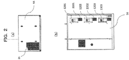
- Fig. 2(a) is a top view of the package-type fluid machine 100.
- An exhaust port 21 through which gas that has cooled the inverter, the compression portion, and a primary aftercooler is exhausted to the outside is disposed in a leftward direction of the front surface side in an upper surface of the casing 16.
- Fig. 2(b) is a back view of the package-type fluid machine 100.
- the first stage inverter 1201, the second stage inverter 1202, and the third stage inverter 1203 are disposed in a back surface of the casing 16 in order from above.
- the casing 16 is provided with a first stage back intake port 2201 for an inverter which takes in outside air to cool the first stage inverter 1201, a second stage back intake port 2202 for an inverter which cools the second stage inverter 1202, and a third stage back intake port 2203 for an inverter which cools the third stage inverter 1203 in order from above.
- Fig. 3(a) is a view illustrating an internal configuration of the package-type fluid machine 100 when seen from the front.
- a first stage compressor unit 3101, a second stage compressor unit 3102, and a third stage compressor unit 3103 are disposed in a central portion of the package-type fluid machine 100 in order from above.
- the operation panel 11 which receives an operation instruction or displays a warning or the like is disposed on a right side of the first stage compressor unit 3101.
- Fig. 3(b) is a view illustrating an internal configuration of the side surface on the left side of the package-type fluid machine 100 when seen from the front.
- a first stage primary aftercooler 3201 which cools the fluid compressed by a compression portion of the first stage compressor unit 3101, a second stage primary aftercooler 3202 which cools the fluid compressed by a compression portion of the second stage compressor unit 3102, and a third stage primary aftercooler 3203 which cools the fluid compressed by a compression portion of the third stage compressor unit 3103 are disposed on a front surface side of the left side surface of the package-type fluid machine 100 in order from above.
- the first stage inverter 1201 which controls a motor of the first stage compressor unit 3101, the second stage inverter 1202 which controls a motor of the second stage compressor unit 3102, and the third stage inverter 1203 which controls a motor of the third stage compressor unit 3103 are disposed in order from above on the back surface side of the side surface of the package-type fluid machine 100 when seen from the left.
- Fig. 3(c) is a view illustrating an internal configuration on the right side of the package-type fluid machine 100 when seen from the front.
- a secondary aftercooler or a dryer that cools the compressed fluid which has passed through the primary aftercoolers is disposed on the right side of the package-type fluid machine 100 when seen from the front.
- the primary aftercoolers 3201, 3202, and 3203 are disposed on the left side when seen from the front, the secondary aftercooler and the dryer are separately disposed on the right side when seen from the front, and the primary aftercoolers 3201, 3201, and 3203 are disposed on the front surface side. In such a manner, maintenance work of the primary aftercoolers 3201, 3201, and 3203 can be easily performed from the front surface side.
- Fig. 4(a) is a view illustrating an internal configuration of the package-type fluid machine 100 when seen from the back.
- a first stage cooling duct 4101 of the first stage compressor unit 3101, a second stage cooling duct 4102 of the second stage compressor unit 3102, and a third stage cooling duct 4103 of the third stage compressor unit 3103 are disposed in a central portion of the package-type fluid machine 100 in order from above.
- the first stage inverter 1201, the second stage inverter 1202, and the third stage inverter 1203 are disposed in order from above on the right side when seen from the back.
- Fig. 4(b) is a view illustrating an internal configuration of the package-type fluid machine 100 when seen from the top.
- the first stage compressor unit 3101 is disposed in a central portion, and the compression portion, the motor, and a cooling fan are disposed in a backward direction in order from the front surface side.
- the cooling duct 4101 which allows the cooling gas to flow from the cooling fan toward the compression portion and extends toward the front surface side is disposed on the right side of the first stage compressor unit 3101 when seen from the front.
- a cooling duct having the same configuration is disposed below the first stage compressor unit 3101.
- the first stage primary aftercooler 3201 is disposed on the left side of the package-type fluid machine 100 when seen from the front.
- first stage inverter 1201 is disposed on a back surface side of the first stage primary aftercooler 3201.
- Fig. 5 is a perspective view illustrating an internal configuration of the package-type fluid machine 100 in the first embodiment.
- Drawer mechanisms 33 including pedestals on which the compressor units 3101, 3102, and 3103 are placed, respectively, are provided. When maintenance is performed, the drawer mechanisms 33 can be used to draw the compressor units 3101, 3102, and 3103 out to the front surface, respectively.
- the drawer mechanism 33 includes the pedestal, a rail, a caster, and the like.
- An inverter intake port which takes in outside air into an inverter chamber 34 where the inverter is disposed is provided in a side surface and a back surface of each of the inverter chambers.
- the cooling gas which is taken in from the inverter intake port by the drive of the cooling fan is suctioned toward the cooling fan through an opening 53 provided in a partition wall 52 that partitions off the inverter chamber 34 from a machine chamber 54 which is adjacent to the inverter chamber 34 and in which compressor units 31 are disposed.
- the cooling gas cools the compression portion and cools the primary aftercooler 3201 through the cooling duct 4101 illustrated in Fig. 4 , and then is released to the outside from the exhaust port 21 through an exhaust duct 51.
- inverter intake ports 2201, 2202, and 2203 are provided below the inverters, respectively, and the opening 53 is provided on an upper side of each of the inverters. Since the inverter intake port 2201 and the opening 53 are located at different upper and lower positions, the cooling gas taken in from the intake port flows by the inverter from below to above, so that the entirety of the inverter can be cooled.
- the positional relationship between the inverter intake port and the opening may be such that the inverter intake port is located on an upper side and the opening is located on a lower side.
- At least three openings 53 are provided in the partition wall 52 to correspond to the stages of the compressor units 3101, 3102, and 3103, respectively.
- the inverter chamber 34 including the inverter intake port and the machine chamber 54 in which the compressor unit 3101 is disposed are disposed on a back surface side of the package-type fluid machine 100 in a state where both the chambers are adjacent to each other. Further, the opening 53 is provided on the back surface side of the package-type fluid machine 100, and the cooling fan is disposed on a side where the opening 53 is located. For this reason, unlike Patent Document 1, the intake port and the cooling fan are not separated from each other by the length of the motor or more.
- the cooling gas having a flow rate sufficient to cool the inverter or the compression portion can be suctioned from the inverter intake port by the drive of the cooling fan, so that the cooling efficiency of the inverter or the like can be improved.
- the exhaust duct 51 is disposed on a front surface side of a left side of the machine chamber 54, in which the compressor units 3101, 3102, and 3103 are disposed, when seen from the front.
- the inverter chambers 34 are disposed in three stages on a back surface side of the exhaust duct 51 to correspond to the compressor units 3101, 3102, and 3103, and the inverter which controls the motor is disposed in each of the inverter chambers 34.
- the compressor units 3101, 3102, and 3103 which are longer than the longitudinal dimension of the exhaust duct 51 are disposed on a right side of the exhaust duct 51 when seen from the front. Therefore, in order to effectively utilize a space on the back surface side of the exhaust duct 51, the inverter chambers 34 are disposed on the back surface side of the exhaust duct 51, so that the size of the package-type fluid machine 100 can be reduced.
- Fig. 6 is a view for describing the compressor unit 31.
- the compressor unit 31 includes a compression portion 61, a motor 62, and a cooling fan 63.
- the compression portion 61 is a scroll compressor
- the motor 62 is an axial gap type motor.
- a sirocco fan is used as the cooling fan 63.
- the compression portion 61, the motor 62, and the cooling fan 63 are disposed from the front surface side toward the backward direction.
- the compression portion 61 having a high maintenance frequency is disposed on the front surface side. For this reason, when the drawer mechanism 33 is used to draw the compression portion 61 out, maintenance work can be easily performed.
- the motor 62 and the compression portion 61 of the compressor unit 31 are combined to form a compressor unit integrated with a motor. Since the motor 62 is an axial gap type motor having a structure where a rotor disposed in a disk shape and a stator rotate while facing each other, the motor 62 can be made thin. Further, since amorphous which is a material having high magnetic permeability and small core loss is used as the material of a stator core, the efficiency of the motor can be improved and the size of the motor can be further reduced.
- the cooling fan 63 is installed on an end portion side of a rotary shaft 64 rotated by the motor 62.
- the cooling fan 63 has a structure where rotary blades mounted on the rotary shaft 64 are accommodated inside a fan cover made of resin.
- the cooling fan 63 is a so-called suction type cooling fan that suctions outside air, which flows into the cooling fan 63 from a side surface of the cooling fan 63 by the rotation of the rotary blades driven by the rotary shaft 64, to generate cooling air.
- the cooling air generated inside the fan cover by the rotation of the rotary blades is supplied to a fixed scroll or an orbiting scroll of the scroll compressor, which is the compression portion 61, through the cooling duct 4101 (refer to Fig. 4(b) ) that is provided in a right side surface of the compressor unit 31 when seen from the front.
- the number of the stages of the inverters, the compressor units, or the primary aftercoolers is 3 has been described; however, the number of the stages is not limited to 3, and a plurality of stages may be provided to make the set area of the package-type fluid machine 100 compact.
- the compression portion is a scroll compressor and the motor is an axial gap type motor in which amorphous is used as the material of the stator core
- the compression portion may be a compressor such as a reciprocating compressor other than the scroll compressor.
- a motor having another configuration, such as a radial gap type motor can be used as the motor.
Landscapes
- Engineering & Computer Science (AREA)
- Mechanical Engineering (AREA)
- General Engineering & Computer Science (AREA)
- Microelectronics & Electronic Packaging (AREA)
- Physics & Mathematics (AREA)
- Thermal Sciences (AREA)
- Power Engineering (AREA)
- Applications Or Details Of Rotary Compressors (AREA)
- Compressor (AREA)
Abstract
Description
- The present invention relates to a package-type fluid machine, particularly to a package-type fluid machine suitable for cooling an inverter.
- There is known a gas compressor that generates compressed gas and is used as a power source in a production line or an air source for a machine tool, a press machine, an air blower, or the like. The gas compressor includes a compression portion that compresses the gas in a compression chamber formed by a casing, and the compressed gas is discharged from a discharge port to a gas tank via a discharge pipe.
- In addition, there is a package-type fluid machine in which a compression portion, a motor that drives the compression portion, a control circuit, an operation panel, and the like are integrated into a package to save space. In the package-type fluid machine, the compression portion and an inverter are required to be cooled.
- There is Patent Document 1 as a background art relating to the cooling of a package-type fluid machine. In Patent Document 1, a compression portion is provided with a cooling fan. Further, an inverter is provided in an intake path through which cooling air generated by the cooling fan flows. It is described that a package-type compressor in which restriction on the disposition of components is reduced to improve productivity while cooling of the inverter is secured can be obtained with such a configuration.
- Patent Document 1:
JP 2016-75159 A - In the package-type compressor disclosed in Patent Document 1, the compression portion to which the cooling fan is attached is disposed below a motor, and the inverter is disposed in an upper portion with respect to the compression portion. In addition, the inverter and the cooling fan are separated from each other by the length in a lateral direction of the motor, and the interval between an intake port and the cooling fan is long. For this reason, there is a possibility that the flow rate of the cooling air suctioned by the cooling fan is reduced to cause a decrease in cooling efficiency.
- An object of the present invention is to provide a package-type fluid machine in which the cooling efficiency of an inverter is improved.
- According to one exemplary example of the present invention, there is provided a package-type fluid machine including: a compressor unit including a compression portion that compresses a fluid, a motor that drives the compression portion, and a cooling fan that is driven by the motor; a machine chamber in which the compressor unit is disposed; an inverter chamber which is adjacent to the machine chamber and in which an inverter is disposed; a partition wall that partitions off the machine chamber from the inverter chamber and has an opening; and an inverter intake port that is disposed in the inverter chamber to take in a cooling gas. The cooling fan is disposed on a side of the machine chamber, the opening being located on the side. The cooling fan is driven to cause the cooling gas to flow from the inverter intake port to the opening to cool the inverter.
- According to the present invention, a package-type fluid machine in which the cooling efficiency of the inverter is improved can be realized.
-
-
Fig. 1 illustrates a front view and side views of a package-type fluid machine in a first embodiment. -
Fig. 2 illustrates a top view and a back view of the package-type fluid machine in the first embodiment. -
Fig. 3 illustrates internal configuration views of the package-type fluid machine in the first embodiment when seen from the front and the side. -
Fig. 4 illustrates internal configuration views of the package-type fluid machine in the first embodiment when seen from the back and the top. -
Fig. 5 is a perspective view illustrating an internal configuration of the package-type fluid machine in the first embodiment. -
Fig. 6 is a view illustrating a compressor unit of the package-type fluid machine. - Hereinafter, an embodiment of the present invention will be described with reference to the drawings.
-
Fig. 1(a) is a front view of a package-type fluid machine 100 in a first embodiment. Afront panel 15 forming a part of a casing of the package-type fluid machine 100 can be attached to and removed from a portion of the casing other than the front panel by a holding mechanism such as screws. - In addition, an
operation panel 11 through which the package-type fluid machine 100 is operated is disposed in a front surface of the package-type fluid machine 100. - The
front panel 15 is a panel that covers the front surface of the package-type fluid machine 100 except a position where the operation panel is located, and when thefront panel 15 is removed, maintenance of internal components or the like can be performed. -
Fig. 1(b) is a side view on a left side of the package-type fluid machine 100 when seen from the front. - A
first stage inverter 1201, asecond stage inverter 1202, and athird stage inverter 1203 illustrated by dotted lines are disposed on a back surface side of a left side surface of acasing 16 in order from above. - In addition, the
casing 16 is provided with a first stageside intake port 1301 for an inverter which takes in outside air to cool thefirst stage inverter 1201, a second stageside intake port 1302 for an inverter which cools thesecond stage inverter 1202, and a third stageside intake port 1303 for an inverter which cools thethird stage inverter 1203 in order from above. -
Fig. 1(c) is a side view on a right side of the package-type fluid machine 100 when seen from the front. - A first
main intake port 1401, a secondmain intake port 1402, and a thirdmain intake port 1403 that take in outside air which is a fluid to be compressed by a compression portion are disposed from above on a front surface side of a right side surface of thecasing 16. - The
side intake ports main intake ports -
Fig. 2(a) is a top view of the package-type fluid machine 100. - An
exhaust port 21 through which gas that has cooled the inverter, the compression portion, and a primary aftercooler is exhausted to the outside is disposed in a leftward direction of the front surface side in an upper surface of thecasing 16. -
Fig. 2(b) is a back view of the package-type fluid machine 100. - As illustrated by dotted lines, the
first stage inverter 1201, thesecond stage inverter 1202, and thethird stage inverter 1203 are disposed in a back surface of thecasing 16 in order from above. - In addition, the
casing 16 is provided with a first stageback intake port 2201 for an inverter which takes in outside air to cool thefirst stage inverter 1201, a second stageback intake port 2202 for an inverter which cools thesecond stage inverter 1202, and a third stageback intake port 2203 for an inverter which cools thethird stage inverter 1203 in order from above. -
Fig. 3(a) is a view illustrating an internal configuration of the package-type fluid machine 100 when seen from the front. - A first
stage compressor unit 3101, a secondstage compressor unit 3102, and a thirdstage compressor unit 3103 are disposed in a central portion of the package-type fluid machine 100 in order from above. - The
operation panel 11 which receives an operation instruction or displays a warning or the like is disposed on a right side of the firststage compressor unit 3101. -
Fig. 3(b) is a view illustrating an internal configuration of the side surface on the left side of the package-type fluid machine 100 when seen from the front. - A first stage
primary aftercooler 3201 which cools the fluid compressed by a compression portion of the firststage compressor unit 3101, a second stageprimary aftercooler 3202 which cools the fluid compressed by a compression portion of the secondstage compressor unit 3102, and a third stageprimary aftercooler 3203 which cools the fluid compressed by a compression portion of the thirdstage compressor unit 3103 are disposed on a front surface side of the left side surface of the package-type fluid machine 100 in order from above. - The
first stage inverter 1201 which controls a motor of the firststage compressor unit 3101, thesecond stage inverter 1202 which controls a motor of the secondstage compressor unit 3102, and thethird stage inverter 1203 which controls a motor of the thirdstage compressor unit 3103 are disposed in order from above on the back surface side of the side surface of the package-type fluid machine 100 when seen from the left. -
Fig. 3(c) is a view illustrating an internal configuration on the right side of the package-type fluid machine 100 when seen from the front. A secondary aftercooler or a dryer that cools the compressed fluid which has passed through the primary aftercoolers is disposed on the right side of the package-type fluid machine 100 when seen from the front. - The
primary aftercoolers primary aftercoolers primary aftercoolers -
Fig. 4(a) is a view illustrating an internal configuration of the package-type fluid machine 100 when seen from the back. A firststage cooling duct 4101 of the firststage compressor unit 3101, a secondstage cooling duct 4102 of the secondstage compressor unit 3102, and a thirdstage cooling duct 4103 of the thirdstage compressor unit 3103 are disposed in a central portion of the package-type fluid machine 100 in order from above. - The
first stage inverter 1201, thesecond stage inverter 1202, and thethird stage inverter 1203 are disposed in order from above on the right side when seen from the back. -
Fig. 4(b) is a view illustrating an internal configuration of the package-type fluid machine 100 when seen from the top. - The first
stage compressor unit 3101 is disposed in a central portion, and the compression portion, the motor, and a cooling fan are disposed in a backward direction in order from the front surface side. - The
cooling duct 4101 which allows the cooling gas to flow from the cooling fan toward the compression portion and extends toward the front surface side is disposed on the right side of the firststage compressor unit 3101 when seen from the front. A cooling duct having the same configuration is disposed below the firststage compressor unit 3101. - The first stage
primary aftercooler 3201 is disposed on the left side of the package-type fluid machine 100 when seen from the front. - In addition, the
first stage inverter 1201 is disposed on a back surface side of the first stageprimary aftercooler 3201. -
Fig. 5 is a perspective view illustrating an internal configuration of the package-type fluid machine 100 in the first embodiment. -
Drawer mechanisms 33 including pedestals on which thecompressor units drawer mechanisms 33 can be used to draw thecompressor units drawer mechanism 33 includes the pedestal, a rail, a caster, and the like. - An inverter intake port which takes in outside air into an
inverter chamber 34 where the inverter is disposed is provided in a side surface and a back surface of each of the inverter chambers. The cooling gas which is taken in from the inverter intake port by the drive of the cooling fan is suctioned toward the cooling fan through anopening 53 provided in apartition wall 52 that partitions off theinverter chamber 34 from amachine chamber 54 which is adjacent to theinverter chamber 34 and in whichcompressor units 31 are disposed. - Then, the cooling gas cools the compression portion and cools the
primary aftercooler 3201 through the coolingduct 4101 illustrated inFig. 4 , and then is released to the outside from theexhaust port 21 through anexhaust duct 51. - As illustrated in
Fig. 2(b) , on a back surface of each stage of the inverters,inverter intake ports opening 53 is provided on an upper side of each of the inverters. Since theinverter intake port 2201 and theopening 53 are located at different upper and lower positions, the cooling gas taken in from the intake port flows by the inverter from below to above, so that the entirety of the inverter can be cooled. The positional relationship between the inverter intake port and the opening may be such that the inverter intake port is located on an upper side and the opening is located on a lower side. - At least three
openings 53 are provided in thepartition wall 52 to correspond to the stages of thecompressor units - The
inverter chamber 34 including the inverter intake port and themachine chamber 54 in which thecompressor unit 3101 is disposed are disposed on a back surface side of the package-type fluid machine 100 in a state where both the chambers are adjacent to each other. Further, theopening 53 is provided on the back surface side of the package-type fluid machine 100, and the cooling fan is disposed on a side where theopening 53 is located. For this reason, unlike Patent Document 1, the intake port and the cooling fan are not separated from each other by the length of the motor or more. As a result, according to the first embodiment, the cooling gas having a flow rate sufficient to cool the inverter or the compression portion can be suctioned from the inverter intake port by the drive of the cooling fan, so that the cooling efficiency of the inverter or the like can be improved. - The
exhaust duct 51 is disposed on a front surface side of a left side of themachine chamber 54, in which thecompressor units - The
inverter chambers 34 are disposed in three stages on a back surface side of theexhaust duct 51 to correspond to thecompressor units inverter chambers 34. - As illustrated in
Fig. 5 , thecompressor units exhaust duct 51 are disposed on a right side of theexhaust duct 51 when seen from the front. Therefore, in order to effectively utilize a space on the back surface side of theexhaust duct 51, theinverter chambers 34 are disposed on the back surface side of theexhaust duct 51, so that the size of the package-type fluid machine 100 can be reduced. -
Fig. 6 is a view for describing thecompressor unit 31. Thecompressor unit 31 includes acompression portion 61, amotor 62, and a coolingfan 63. In the present embodiment, thecompression portion 61 is a scroll compressor, and themotor 62 is an axial gap type motor. A sirocco fan is used as the coolingfan 63. - In each of the
compressor units compression portion 61, themotor 62, and the coolingfan 63 are disposed from the front surface side toward the backward direction. Thecompression portion 61 having a high maintenance frequency is disposed on the front surface side. For this reason, when thedrawer mechanism 33 is used to draw thecompression portion 61 out, maintenance work can be easily performed. - The
motor 62 and thecompression portion 61 of thecompressor unit 31 are combined to form a compressor unit integrated with a motor. Since themotor 62 is an axial gap type motor having a structure where a rotor disposed in a disk shape and a stator rotate while facing each other, themotor 62 can be made thin. Further, since amorphous which is a material having high magnetic permeability and small core loss is used as the material of a stator core, the efficiency of the motor can be improved and the size of the motor can be further reduced. - The cooling
fan 63 is installed on an end portion side of arotary shaft 64 rotated by themotor 62. The coolingfan 63 has a structure where rotary blades mounted on therotary shaft 64 are accommodated inside a fan cover made of resin. - The cooling
fan 63 is a so-called suction type cooling fan that suctions outside air, which flows into the coolingfan 63 from a side surface of the coolingfan 63 by the rotation of the rotary blades driven by therotary shaft 64, to generate cooling air. - The cooling air generated inside the fan cover by the rotation of the rotary blades is supplied to a fixed scroll or an orbiting scroll of the scroll compressor, which is the
compression portion 61, through the cooling duct 4101 (refer toFig. 4(b) ) that is provided in a right side surface of thecompressor unit 31 when seen from the front. - In the embodiment, a case where the number of the stages of the inverters, the compressor units, or the primary aftercoolers is 3 has been described; however, the number of the stages is not limited to 3, and a plurality of stages may be provided to make the set area of the package-
type fluid machine 100 compact. - In addition, in the embodiment, a case where the compression portion is a scroll compressor and the motor is an axial gap type motor in which amorphous is used as the material of the stator core has been described; however, the compression portion may be a compressor such as a reciprocating compressor other than the scroll compressor. In addition, for example, a motor having another configuration, such as a radial gap type motor, can be used as the motor.
-
- 11
- Operation panel
- 15
- Front panel
- 1201, 1202, 1203
- Inverter
- 16
- Casing
- 21
- Exhaust port
- 2201, 2202, 2203
- Back intake port for inverter
- 31, 3101, 3102, 3103
- Compressor unit
- 3201, 3202, 3203
- Primary aftercooler
- 34
- Inverter chamber
- 51
- Exhaust duct
- 52
- Partition wall
- 53
- Opening
- 54
- Machine chamber
- 61
- Compression portion
- 62
- Motor
- 63
- Cooling fan
- 100
- Package-type fluid machine
Claims (13)
- A package-type fluid machine comprising:a compressor unit including a compression portion that compresses a fluid, a motor that drives the compression portion, and a cooling fan that is driven by the motor;a machine chamber in which the compressor unit is disposed;an inverter chamber which is adjacent to the machine chamber and in which an inverter is disposed;a partition wall that partitions off the machine chamber from the inverter chamber and has an opening; andan inverter intake port that is disposed in the inverter chamber to take in a cooling gas,wherein the cooling fan is disposed on a side of the machine chamber, the opening being located on the side, andthe cooling fan is driven to cause the cooling gas to flow from the inverter intake port to the opening to cool the inverter.
- The package-type fluid machine according to claim 1,
wherein the inverter, the opening, and the cooling fan are disposed on a back surface side. - The package-type fluid machine according to claim 2,
wherein the compression portion is disposed on a front surface side with respect to the motor. - The package-type fluid machine according to claim 1, further comprising:a main intake port that takes in the fluid,wherein the inverter intake port and the main intake port are disposed on opposite sides when seen from a front.
- The package-type fluid machine according to claim 1, further comprising:a plurality of the compressor units and a plurality of the inverters,wherein the compressor units and the inverters are disposed in a plurality of stages in a longitudinal direction.
- The package-type fluid machine according to claim 1,
wherein the inverter intake port and the opening are disposed at different positions in an upward and downward direction. - The package-type fluid machine according to claim 1,
wherein the cooling fan is a sirocco fan. - The package-type fluid machine according to claim 1,
wherein the compressor unit is an integral type in which the compression portion and the motor are combined. - The package-type fluid machine according to claim 8,
wherein the motor is an axial gap type motor. - The package-type fluid machine according to claim 9,
wherein the compression portion is a scroll compressor. - The package-type fluid machine according to claim 1, further comprising:an exhaust duct that exhausts the cooling gas,wherein the inverter chamber is disposed on a back surface side of the exhaust duct.
- The package-type fluid machine according to claim 1,
wherein a cooling duct which supplies the cooling gas to the compression portion is disposed on a side surface of the compressor unit. - The package-type fluid machine according to claim 1, further comprising:a primary aftercooler, a secondary aftercooler, and a dryer that cool the fluid from the compression portion,wherein the compressor unit is disposed in a central portion, the primary aftercooler and the inverter chamber are disposed in one end portion, and the secondary aftercooler and the dryer are disposed in the other end portion.
Applications Claiming Priority (1)
| Application Number | Priority Date | Filing Date | Title |
|---|---|---|---|
| PCT/JP2018/033914 WO2020054008A1 (en) | 2018-09-13 | 2018-09-13 | Package-type fluid machine |
Publications (3)
| Publication Number | Publication Date |
|---|---|
| EP3851672A1 true EP3851672A1 (en) | 2021-07-21 |
| EP3851672A4 EP3851672A4 (en) | 2022-05-04 |
| EP3851672B1 EP3851672B1 (en) | 2025-07-30 |
Family
ID=69776675
Family Applications (1)
| Application Number | Title | Priority Date | Filing Date |
|---|---|---|---|
| EP18933583.9A Active EP3851672B1 (en) | 2018-09-13 | 2018-09-13 | Package-type fluid machine |
Country Status (5)
| Country | Link |
|---|---|
| US (1) | US11937410B2 (en) |
| EP (1) | EP3851672B1 (en) |
| JP (1) | JP6951586B2 (en) |
| CN (1) | CN112292529B (en) |
| WO (1) | WO2020054008A1 (en) |
Family Cites Families (26)
| Publication number | Priority date | Publication date | Assignee | Title |
|---|---|---|---|---|
| SE369543B (en) * | 1973-08-27 | 1974-09-02 | Atlas Copco Ab | |
| US4492533A (en) * | 1980-06-17 | 1985-01-08 | Tokico Ltd. | Air compressor |
| JP2716934B2 (en) * | 1994-04-08 | 1998-02-18 | 株式会社神戸製鋼所 | Package type oil-cooled air compressor |
| JP3866779B2 (en) * | 1995-02-20 | 2007-01-10 | 株式会社日立産機システム | Blower soundproofing device |
| JP3231586B2 (en) * | 1995-09-01 | 2001-11-26 | 株式会社日立製作所 | Air-cooled package type compressor |
| JP3296205B2 (en) * | 1996-09-20 | 2002-06-24 | 株式会社日立製作所 | Oil-free scroll compressor and its cooling system |
| US6447264B1 (en) * | 2001-02-05 | 2002-09-10 | Ingersoll-Rand Company | Compressor system |
| US6793465B2 (en) * | 2002-08-30 | 2004-09-21 | William A. Stallings | Air treatment enclosure |
| JP4255765B2 (en) * | 2003-07-08 | 2009-04-15 | 株式会社日立産機システム | Package type compressor |
| JP2005171958A (en) * | 2003-12-15 | 2005-06-30 | Tokyo Electric Power Co Inc:The | Package type compressor |
| JP4687106B2 (en) * | 2004-12-28 | 2011-05-25 | マックス株式会社 | Air compressor cooling system |
| JP4816358B2 (en) * | 2006-09-19 | 2011-11-16 | ダイキン工業株式会社 | Motor and compressor |
| JP2008133811A (en) | 2006-11-29 | 2008-06-12 | Hitachi Ltd | Package type compressor |
| US8872361B2 (en) * | 2012-01-25 | 2014-10-28 | Briggs & Stratton Corporation | Standby generators including compressed fiberglass components |
| JP2015187506A (en) * | 2012-08-08 | 2015-10-29 | 東芝キヤリア株式会社 | Outdoor unit of refrigeration cycle device |
| JP5802967B2 (en) | 2012-09-10 | 2015-11-04 | オリオン機械株式会社 | Package type rotary pump unit |
| JP5998028B2 (en) | 2012-11-30 | 2016-09-28 | 株式会社日立産機システム | Scroll type fluid machine |
| JP5899150B2 (en) * | 2013-04-19 | 2016-04-06 | 株式会社日立産機システム | Package type fluid machinery |
| US9476416B2 (en) * | 2013-11-22 | 2016-10-25 | Chi-Wen Chen | Air compressor |
| JP5728738B2 (en) * | 2014-01-08 | 2015-06-03 | オリオン機械株式会社 | Package type rotary pump unit |
| JP6313638B2 (en) * | 2014-04-14 | 2018-04-18 | 株式会社日立産機システム | Compressor and gas separation device using the same |
| JP6382672B2 (en) * | 2014-10-02 | 2018-08-29 | 株式会社日立産機システム | Package type compressor |
| KR101720491B1 (en) * | 2015-01-22 | 2017-03-28 | 엘지전자 주식회사 | Centrifugal fan |
| US10928080B2 (en) * | 2015-11-09 | 2021-02-23 | Carrier Corporation | Climate control outdoor unit with inverter cooling |
| JP6654969B2 (en) * | 2016-06-16 | 2020-02-26 | 株式会社神戸製鋼所 | Package type compressor |
| US10537046B1 (en) * | 2018-11-30 | 2020-01-14 | Teco-Westinghouse Motor Company | Cooling methods for medium voltage drive systems |
-
2018
- 2018-09-13 US US17/264,807 patent/US11937410B2/en active Active
- 2018-09-13 EP EP18933583.9A patent/EP3851672B1/en active Active
- 2018-09-13 CN CN201880094957.3A patent/CN112292529B/en active Active
- 2018-09-13 JP JP2020546615A patent/JP6951586B2/en active Active
- 2018-09-13 WO PCT/JP2018/033914 patent/WO2020054008A1/en not_active Ceased
Also Published As
| Publication number | Publication date |
|---|---|
| WO2020054008A1 (en) | 2020-03-19 |
| CN112292529B (en) | 2023-08-22 |
| US20210289670A1 (en) | 2021-09-16 |
| EP3851672A4 (en) | 2022-05-04 |
| CN112292529A (en) | 2021-01-29 |
| JPWO2020054008A1 (en) | 2021-08-30 |
| US11937410B2 (en) | 2024-03-19 |
| EP3851672B1 (en) | 2025-07-30 |
| JP6951586B2 (en) | 2021-10-20 |
Similar Documents
| Publication | Publication Date | Title |
|---|---|---|
| US11473582B2 (en) | Package-type compressor | |
| JP5899150B2 (en) | Package type fluid machinery | |
| US10895155B2 (en) | Package type compressor | |
| WO2019176563A1 (en) | Fluid machine | |
| JP5205041B2 (en) | air compressor | |
| JPH07279877A (en) | Package type oil cooling type air compressor | |
| KR100584653B1 (en) | Package-type fluidic apparatus | |
| CN107208622A (en) | Box fluid machinery | |
| JP6694094B2 (en) | Package type compressor | |
| US11937410B2 (en) | Package-type fluid machine | |
| KR100970719B1 (en) | Enclosure of turbo blower | |
| KR102050810B1 (en) | Turbo machine | |
| JPH11350918A (en) | Gas turbine power generating unit | |
| JP4996142B2 (en) | Package type compressor | |
| JP6986638B2 (en) | Package type fluid machine | |
| JP5345719B2 (en) | Package type compressor with air dryer | |
| CN119616895B (en) | High-efficiency energy-saving centrifugal fan | |
| JP2005171958A (en) | Package type compressor | |
| US11384763B2 (en) | Scroll-type fluid machine with cooling fan including a peripheral wall configured to minimize vortices |
Legal Events
| Date | Code | Title | Description |
|---|---|---|---|
| STAA | Information on the status of an ep patent application or granted ep patent |
Free format text: STATUS: THE INTERNATIONAL PUBLICATION HAS BEEN MADE |
|
| PUAI | Public reference made under article 153(3) epc to a published international application that has entered the european phase |
Free format text: ORIGINAL CODE: 0009012 |
|
| STAA | Information on the status of an ep patent application or granted ep patent |
Free format text: STATUS: REQUEST FOR EXAMINATION WAS MADE |
|
| 17P | Request for examination filed |
Effective date: 20210413 |
|
| AK | Designated contracting states |
Kind code of ref document: A1 Designated state(s): AL AT BE BG CH CY CZ DE DK EE ES FI FR GB GR HR HU IE IS IT LI LT LU LV MC MK MT NL NO PL PT RO RS SE SI SK SM TR |
|
| DAV | Request for validation of the european patent (deleted) | ||
| DAX | Request for extension of the european patent (deleted) | ||
| A4 | Supplementary search report drawn up and despatched |
Effective date: 20220404 |
|
| RIC1 | Information provided on ipc code assigned before grant |
Ipc: F04C 29/04 20060101ALI20220328BHEP Ipc: F01C 21/00 20060101ALI20220328BHEP Ipc: F04B 39/06 20060101AFI20220328BHEP |
|
| STAA | Information on the status of an ep patent application or granted ep patent |
Free format text: STATUS: EXAMINATION IS IN PROGRESS |
|
| 17Q | First examination report despatched |
Effective date: 20240801 |
|
| REG | Reference to a national code |
Ref country code: DE Ref legal event code: R079 Free format text: PREVIOUS MAIN CLASS: F04B0039060000 Ipc: F01C0021000000 Ref country code: DE Ref legal event code: R079 Ref document number: 602018084205 Country of ref document: DE Free format text: PREVIOUS MAIN CLASS: F04B0039060000 Ipc: F01C0021000000 |
|
| GRAP | Despatch of communication of intention to grant a patent |
Free format text: ORIGINAL CODE: EPIDOSNIGR1 |
|
| STAA | Information on the status of an ep patent application or granted ep patent |
Free format text: STATUS: GRANT OF PATENT IS INTENDED |
|
| RIC1 | Information provided on ipc code assigned before grant |
Ipc: F04C 18/02 20060101ALN20250203BHEP Ipc: F04B 39/06 20060101ALN20250203BHEP Ipc: F04B 35/04 20060101ALN20250203BHEP Ipc: H02P 27/06 20060101ALI20250203BHEP Ipc: F04C 29/04 20060101ALI20250203BHEP Ipc: F01C 21/00 20060101AFI20250203BHEP |
|
| INTG | Intention to grant announced |
Effective date: 20250226 |
|
| GRAS | Grant fee paid |
Free format text: ORIGINAL CODE: EPIDOSNIGR3 |
|
| GRAA | (expected) grant |
Free format text: ORIGINAL CODE: 0009210 |
|
| STAA | Information on the status of an ep patent application or granted ep patent |
Free format text: STATUS: THE PATENT HAS BEEN GRANTED |
|
| AK | Designated contracting states |
Kind code of ref document: B1 Designated state(s): AL AT BE BG CH CY CZ DE DK EE ES FI FR GB GR HR HU IE IS IT LI LT LU LV MC MK MT NL NO PL PT RO RS SE SI SK SM TR |
|
| REG | Reference to a national code |
Ref country code: GB Ref legal event code: FG4D |
|
| REG | Reference to a national code |
Ref country code: CH Ref legal event code: EP |
|
| REG | Reference to a national code |
Ref country code: DE Ref legal event code: R096 Ref document number: 602018084205 Country of ref document: DE |
|
| REG | Reference to a national code |
Ref country code: IE Ref legal event code: FG4D |
|
| PGFP | Annual fee paid to national office [announced via postgrant information from national office to epo] |
Ref country code: DE Payment date: 20250828 Year of fee payment: 8 |
|
| PGFP | Annual fee paid to national office [announced via postgrant information from national office to epo] |
Ref country code: BE Payment date: 20250903 Year of fee payment: 8 Ref country code: GB Payment date: 20250901 Year of fee payment: 8 |
|
| PGFP | Annual fee paid to national office [announced via postgrant information from national office to epo] |
Ref country code: FR Payment date: 20250902 Year of fee payment: 8 |
|
| REG | Reference to a national code |
Ref country code: NL Ref legal event code: MP Effective date: 20250730 |
|
| REG | Reference to a national code |
Ref country code: AT Ref legal event code: MK05 Ref document number: 1819120 Country of ref document: AT Kind code of ref document: T Effective date: 20250730 |
|
| PG25 | Lapsed in a contracting state [announced via postgrant information from national office to epo] |
Ref country code: PT Free format text: LAPSE BECAUSE OF FAILURE TO SUBMIT A TRANSLATION OF THE DESCRIPTION OR TO PAY THE FEE WITHIN THE PRESCRIBED TIME-LIMIT Effective date: 20251202 |
|
| PG25 | Lapsed in a contracting state [announced via postgrant information from national office to epo] |
Ref country code: IS Free format text: LAPSE BECAUSE OF FAILURE TO SUBMIT A TRANSLATION OF THE DESCRIPTION OR TO PAY THE FEE WITHIN THE PRESCRIBED TIME-LIMIT Effective date: 20251130 |
|
| PG25 | Lapsed in a contracting state [announced via postgrant information from national office to epo] |
Ref country code: NO Free format text: LAPSE BECAUSE OF FAILURE TO SUBMIT A TRANSLATION OF THE DESCRIPTION OR TO PAY THE FEE WITHIN THE PRESCRIBED TIME-LIMIT Effective date: 20251030 |
|
| REG | Reference to a national code |
Ref country code: LT Ref legal event code: MG9D |
|
| PG25 | Lapsed in a contracting state [announced via postgrant information from national office to epo] |
Ref country code: AT Free format text: LAPSE BECAUSE OF FAILURE TO SUBMIT A TRANSLATION OF THE DESCRIPTION OR TO PAY THE FEE WITHIN THE PRESCRIBED TIME-LIMIT Effective date: 20250730 |
|
| PG25 | Lapsed in a contracting state [announced via postgrant information from national office to epo] |
Ref country code: FI Free format text: LAPSE BECAUSE OF FAILURE TO SUBMIT A TRANSLATION OF THE DESCRIPTION OR TO PAY THE FEE WITHIN THE PRESCRIBED TIME-LIMIT Effective date: 20250730 |
|
| PG25 | Lapsed in a contracting state [announced via postgrant information from national office to epo] |
Ref country code: NL Free format text: LAPSE BECAUSE OF FAILURE TO SUBMIT A TRANSLATION OF THE DESCRIPTION OR TO PAY THE FEE WITHIN THE PRESCRIBED TIME-LIMIT Effective date: 20250730 Ref country code: HR Free format text: LAPSE BECAUSE OF FAILURE TO SUBMIT A TRANSLATION OF THE DESCRIPTION OR TO PAY THE FEE WITHIN THE PRESCRIBED TIME-LIMIT Effective date: 20250730 |
|
| PG25 | Lapsed in a contracting state [announced via postgrant information from national office to epo] |
Ref country code: GR Free format text: LAPSE BECAUSE OF FAILURE TO SUBMIT A TRANSLATION OF THE DESCRIPTION OR TO PAY THE FEE WITHIN THE PRESCRIBED TIME-LIMIT Effective date: 20251031 |
|
| PG25 | Lapsed in a contracting state [announced via postgrant information from national office to epo] |
Ref country code: SE Free format text: LAPSE BECAUSE OF FAILURE TO SUBMIT A TRANSLATION OF THE DESCRIPTION OR TO PAY THE FEE WITHIN THE PRESCRIBED TIME-LIMIT Effective date: 20250730 |
|
| PG25 | Lapsed in a contracting state [announced via postgrant information from national office to epo] |
Ref country code: LV Free format text: LAPSE BECAUSE OF FAILURE TO SUBMIT A TRANSLATION OF THE DESCRIPTION OR TO PAY THE FEE WITHIN THE PRESCRIBED TIME-LIMIT Effective date: 20250730 |
|
| PG25 | Lapsed in a contracting state [announced via postgrant information from national office to epo] |
Ref country code: PL Free format text: LAPSE BECAUSE OF FAILURE TO SUBMIT A TRANSLATION OF THE DESCRIPTION OR TO PAY THE FEE WITHIN THE PRESCRIBED TIME-LIMIT Effective date: 20250730 Ref country code: BG Free format text: LAPSE BECAUSE OF FAILURE TO SUBMIT A TRANSLATION OF THE DESCRIPTION OR TO PAY THE FEE WITHIN THE PRESCRIBED TIME-LIMIT Effective date: 20250730 |
|
| PG25 | Lapsed in a contracting state [announced via postgrant information from national office to epo] |
Ref country code: RS Free format text: LAPSE BECAUSE OF FAILURE TO SUBMIT A TRANSLATION OF THE DESCRIPTION OR TO PAY THE FEE WITHIN THE PRESCRIBED TIME-LIMIT Effective date: 20251030 |
|
| PG25 | Lapsed in a contracting state [announced via postgrant information from national office to epo] |
Ref country code: ES Free format text: LAPSE BECAUSE OF FAILURE TO SUBMIT A TRANSLATION OF THE DESCRIPTION OR TO PAY THE FEE WITHIN THE PRESCRIBED TIME-LIMIT Effective date: 20250730 |
|
| PG25 | Lapsed in a contracting state [announced via postgrant information from national office to epo] |
Ref country code: RO Free format text: LAPSE BECAUSE OF FAILURE TO SUBMIT A TRANSLATION OF THE DESCRIPTION OR TO PAY THE FEE WITHIN THE PRESCRIBED TIME-LIMIT Effective date: 20250730 |
|
| PG25 | Lapsed in a contracting state [announced via postgrant information from national office to epo] |
Ref country code: SM Free format text: LAPSE BECAUSE OF FAILURE TO SUBMIT A TRANSLATION OF THE DESCRIPTION OR TO PAY THE FEE WITHIN THE PRESCRIBED TIME-LIMIT Effective date: 20250730 |
|
| PG25 | Lapsed in a contracting state [announced via postgrant information from national office to epo] |
Ref country code: DK Free format text: LAPSE BECAUSE OF FAILURE TO SUBMIT A TRANSLATION OF THE DESCRIPTION OR TO PAY THE FEE WITHIN THE PRESCRIBED TIME-LIMIT Effective date: 20250730 |
|
| PG25 | Lapsed in a contracting state [announced via postgrant information from national office to epo] |
Ref country code: IT Free format text: LAPSE BECAUSE OF FAILURE TO SUBMIT A TRANSLATION OF THE DESCRIPTION OR TO PAY THE FEE WITHIN THE PRESCRIBED TIME-LIMIT Effective date: 20250730 |
|
| PG25 | Lapsed in a contracting state [announced via postgrant information from national office to epo] |
Ref country code: CZ Free format text: LAPSE BECAUSE OF FAILURE TO SUBMIT A TRANSLATION OF THE DESCRIPTION OR TO PAY THE FEE WITHIN THE PRESCRIBED TIME-LIMIT Effective date: 20250730 |
|
| PG25 | Lapsed in a contracting state [announced via postgrant information from national office to epo] |
Ref country code: SK Free format text: LAPSE BECAUSE OF FAILURE TO SUBMIT A TRANSLATION OF THE DESCRIPTION OR TO PAY THE FEE WITHIN THE PRESCRIBED TIME-LIMIT Effective date: 20250730 Ref country code: EE Free format text: LAPSE BECAUSE OF FAILURE TO SUBMIT A TRANSLATION OF THE DESCRIPTION OR TO PAY THE FEE WITHIN THE PRESCRIBED TIME-LIMIT Effective date: 20250730 |
|
| REG | Reference to a national code |
Ref country code: CH Ref legal event code: H13 Free format text: ST27 STATUS EVENT CODE: U-0-0-H10-H13 (AS PROVIDED BY THE NATIONAL OFFICE) Effective date: 20260504 |