EP3851623A1 - Control system, door handle device, control device, and control method - Google Patents
Control system, door handle device, control device, and control method Download PDFInfo
- Publication number
- EP3851623A1 EP3851623A1 EP19861080.0A EP19861080A EP3851623A1 EP 3851623 A1 EP3851623 A1 EP 3851623A1 EP 19861080 A EP19861080 A EP 19861080A EP 3851623 A1 EP3851623 A1 EP 3851623A1
- Authority
- EP
- European Patent Office
- Prior art keywords
- force
- door
- door handle
- contact
- control
- Prior art date
- Legal status (The legal status is an assumption and is not a legal conclusion. Google has not performed a legal analysis and makes no representation as to the accuracy of the status listed.)
- Granted
Links
Images




Classifications
-
- E—FIXED CONSTRUCTIONS
- E05—LOCKS; KEYS; WINDOW OR DOOR FITTINGS; SAFES
- E05F—DEVICES FOR MOVING WINGS INTO OPEN OR CLOSED POSITION; CHECKS FOR WINGS; WING FITTINGS NOT OTHERWISE PROVIDED FOR, CONCERNED WITH THE FUNCTIONING OF THE WING
- E05F15/00—Power-operated mechanisms for wings
- E05F15/70—Power-operated mechanisms for wings with automatic actuation
- E05F15/73—Power-operated mechanisms for wings with automatic actuation responsive to movement or presence of persons or objects
- E05F15/75—Power-operated mechanisms for wings with automatic actuation responsive to movement or presence of persons or objects responsive to the weight or other physical contact of a person or object
-
- E—FIXED CONSTRUCTIONS
- E05—LOCKS; KEYS; WINDOW OR DOOR FITTINGS; SAFES
- E05B—LOCKS; ACCESSORIES THEREFOR; HANDCUFFS
- E05B81/00—Power-actuated vehicle locks
- E05B81/54—Electrical circuits
- E05B81/64—Monitoring or sensing, e.g. by using switches or sensors
- E05B81/76—Detection of handle operation; Detection of a user approaching a handle; Electrical switching actions performed by door handles
-
- E—FIXED CONSTRUCTIONS
- E05—LOCKS; KEYS; WINDOW OR DOOR FITTINGS; SAFES
- E05B—LOCKS; ACCESSORIES THEREFOR; HANDCUFFS
- E05B81/00—Power-actuated vehicle locks
- E05B81/54—Electrical circuits
- E05B81/64—Monitoring or sensing, e.g. by using switches or sensors
- E05B81/76—Detection of handle operation; Detection of a user approaching a handle; Electrical switching actions performed by door handles
- E05B81/77—Detection of handle operation; Detection of a user approaching a handle; Electrical switching actions performed by door handles comprising sensors detecting the presence of the hand of a user
-
- E—FIXED CONSTRUCTIONS
- E05—LOCKS; KEYS; WINDOW OR DOOR FITTINGS; SAFES
- E05B—LOCKS; ACCESSORIES THEREFOR; HANDCUFFS
- E05B85/00—Details of vehicle locks not provided for in groups E05B77/00 - E05B83/00
- E05B85/10—Handles
- E05B85/12—Inner door handles
-
- E—FIXED CONSTRUCTIONS
- E05—LOCKS; KEYS; WINDOW OR DOOR FITTINGS; SAFES
- E05F—DEVICES FOR MOVING WINGS INTO OPEN OR CLOSED POSITION; CHECKS FOR WINGS; WING FITTINGS NOT OTHERWISE PROVIDED FOR, CONCERNED WITH THE FUNCTIONING OF THE WING
- E05F15/00—Power-operated mechanisms for wings
- E05F15/40—Safety devices, e.g. detection of obstructions or end positions
- E05F15/41—Detection by monitoring transmitted force or torque; Safety couplings with activation dependent upon torque or force, e.g. slip couplings
-
- E—FIXED CONSTRUCTIONS
- E05—LOCKS; KEYS; WINDOW OR DOOR FITTINGS; SAFES
- E05F—DEVICES FOR MOVING WINGS INTO OPEN OR CLOSED POSITION; CHECKS FOR WINGS; WING FITTINGS NOT OTHERWISE PROVIDED FOR, CONCERNED WITH THE FUNCTIONING OF THE WING
- E05F15/00—Power-operated mechanisms for wings
- E05F15/70—Power-operated mechanisms for wings with automatic actuation
- E05F15/77—Power-operated mechanisms for wings with automatic actuation using wireless control
-
- B—PERFORMING OPERATIONS; TRANSPORTING
- B60—VEHICLES IN GENERAL
- B60R—VEHICLES, VEHICLE FITTINGS, OR VEHICLE PARTS, NOT OTHERWISE PROVIDED FOR
- B60R25/00—Fittings or systems for preventing or indicating unauthorised use or theft of vehicles
- B60R25/10—Fittings or systems for preventing or indicating unauthorised use or theft of vehicles actuating a signalling device
- B60R25/1001—Alarm systems associated with another car fitting or mechanism, e.g. door lock or knob, pedals
-
- E—FIXED CONSTRUCTIONS
- E05—LOCKS; KEYS; WINDOW OR DOOR FITTINGS; SAFES
- E05Y—INDEXING SCHEME ASSOCIATED WITH SUBCLASSES E05D AND E05F, RELATING TO CONSTRUCTION ELEMENTS, ELECTRIC CONTROL, POWER SUPPLY, POWER SIGNAL OR TRANSMISSION, USER INTERFACES, MOUNTING OR COUPLING, DETAILS, ACCESSORIES, AUXILIARY OPERATIONS NOT OTHERWISE PROVIDED FOR, APPLICATION THEREOF
- E05Y2900/00—Application of doors, windows, wings or fittings thereof
- E05Y2900/50—Application of doors, windows, wings or fittings thereof for vehicles
- E05Y2900/53—Type of wing
- E05Y2900/531—Doors
Definitions
- the present invention relates to a control system, a door handle apparatus, a control apparatus, and a control method.
- Patent Document 1 describes a technology in which an in-vehicle unit controls the opening of a sliding door of a vehicle when contact between a user and a door handle of the sliding door is detected by a touch sensor installed on the door handle.
- Patent Document 2 describes a technology in which a control apparatus locks or unlocks a vehicle when contact between a user's finger and a door handle of the vehicle is detected by a capacitive sensor installed on the door handle.
- a control system includes a contact sensing means configured to detect contact between an operation body and a door handle, a force sensing means configured to detect a force applied by the operation body to the door handle, and a control means configured to control opening or closing of a door when the contact is detected by the contact sensing means and the force is detected by the force sensing means.
- a control system capable of controlling the opening and closing of a door based on information from sensors in order to avoid an unintended opening/closing operation of the door is provided.
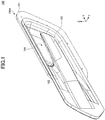
- FIG. 1 is a perspective view of the exterior of a door handle apparatus 100 according to an embodiment.
- FIG. 2 is a front view of the door handle apparatus 100 according to the embodiment.
- FIG. 3 is a rear view of the door handle apparatus 100 according to the embodiment.
- FIG. 4 is a top view of the door handle apparatus 100 according to the embodiment.
- a Z-axis direction (corresponding to the height direction of a vehicle) is referred to as a vertical direction
- a Y-axis direction (corresponding to the width direction of the vehicle)
- a lateral direction a lateral direction
- an X-axis direction (corresponding to the lengthwise direction of the vehicle) is referred to as a longitudinal direction.
- the door handle apparatus 100 illustrated in FIG. 1 through FIG. 4 is integrally formed with an inner panel (not illustrated) of a vehicle door by being fitted into an opening, having approximately the same shape as the door handle apparatus 100, of the inner panel, and is used to allow a user to open/close the vehicle door.
- the door handle apparatus 100 includes a body 100A.
- the body 100A forms the external shape of the door handle apparatus 100.
- the body 100A may be formed of a resin material such as an acrylonitrile butadiene styrene (ABS) resin or a polycarbonate (PC) resin.
- the body 100A includes a base plate 101, a door handle case 102, and a door handle 103, which are integrally formed.
- the base plate 101 has a flat plate shape. Further, the base plate 101 supports the door handle case 102 and the door handle 103, and is fixed to the vehicle door.
- the door handle case 102 has a flat plate shape. Further, the door handle case 102 is disposed closer to the inside of the vehicle than the base plate 101, and is coupled to the base plate 101. The door handle case 102 is exposed to the inside of the vehicle with the door handle apparatus 100 being fitted into the inner panel of the vehicle door.
- the door handle 103 has a hollow plate shape and extends linearly in the longitudinal direction (the X-axis direction).
- the door handle 103 is held by the user's hand when the user performs operations (such as opening/closing of the vehicle door and locking/unlocking of a locking mechanism of the vehicle).
- the rear end portion (the end portion on the negative X-side) of the door handle 103 is connected to the door handle case 102, and is integrally formed with the door handle case 102.
- the door handle 103 is not movable and is configured to slightly bend and deform in response to an operating force being applied by the user.
- the body 100A has a recess 104 that is recessed toward the outside of the vehicle (toward the negative Y-side) in the surroundings of the door handle 103.
- the door handle apparatus 100 allows the user to reach the back side of the door handle 103. Accordingly, both the front side (closer to the inside of the vehicle) and the back side (closer to the outside of the vehicle) of the door handle 103 can be readily held by the user's hand.
- FIG. 5 is a perspective view of the exterior of the door handle apparatus 100 (from which a second case 102B is removed) according to the embodiment.
- FIG. 6 is a front view of the door handle apparatus 100 (from which the second case 102B is removed) according to the embodiment.
- FIG. 7 is a perspective view of the door handle apparatus 100 (from which the second case 102B is removed) as viewed from the front according to the embodiment.
- the door handle case 102 of the body 100A can be divided into a first case 102A disposed closer to the outside of the vehicle, and the second case 102B disposed closer to the inside of the vehicle.
- the first case 102A is fixed to the base plate 101.
- the door handle case 102 has a hollow structure. As illustrated in FIG. 5 , the interior of the door handle case 102 can be exposed by removing the second case 102B from the first case 102A.
- the door handle 103 is provided across the first case 102A and the second case 102B. Therefore, as illustrated in FIG. 5 , when the door handle case 102 is divided into the first case 102A and the second case 102B, the door handle 103 can be divided into a first handle 103A that is integrally formed with the first case 102A, and a second handle 103B that is integrally formed with the second case 102B.
- a contact sensing unit 110 and a force sensing unit 120 are provided in the interior of the door handle case 102.
- the contact sensing unit 110 is an example of a "contact sensing means".
- the contact sensing unit 110 includes a first capacitance sensor 111 and a second capacitance sensor 112.
- Each of the first capacitance sensor 111 and the second capacitance sensor 112 is a thin, flat, rectangular shape and is elongated as viewed in the Y-axis direction in planar view.
- the first capacitance sensor 111 is stacked on the second capacitance sensor 112 in the Y-axis direction within the door handle 103.
- the first capacitance sensor 111 is an example of a "first contact sensor".
- the first capacitance sensor 111 is disposed on the back side (on the negative Y-side) of the door handle 103, and is configured to detect contact of an operation body with the back side of the door handle 103.
- the first capacitance sensor 111 includes detection electrodes, and upon the operation body contacting the back side of the door handle 103, the first capacitance sensor 111 outputs a current value corresponding to the capacitance between the operation body and each of the detection electrodes as a first contact detection signal.
- the second capacitance sensor 112 is an example of a "second contact sensor".
- the second capacitance sensor 112 is disposed on the front side (on the positive Y-side) of the door handle 103, and detects contact of the operation body with the front side of the door handle 103.
- the second capacitance sensor 112 includes detection electrodes, and upon the operation body contacting the front side of the door handle 103, the second capacitance sensor 112 outputs a current value corresponding to the capacitance between the operation body and each of the detection electrodes as a second contact detection signal.
- the force sensing unit 120 includes a metal shaft 121, a holder 122, a sensor base 123, and a strain gauge 124.
- the strain gauge 124 is connected to the rear end portion of the metal shaft 121. Note that the strain gauge 124 is difficult to be seen from the outside, and is indicated by a hidden line in FIG. 7 . A configuration of the strain gauge 124 will be described later in detail with reference to FIG. 9 .
- the metal shaft 121 is an example of a "transmitting means".
- the metal shaft 121 is made of metal and has a rod shape.
- the metal shaft 121 extends linearly in the longitudinal direction (in the X-axis direction) within the door handle case 102.
- the metal shaft 121 is configured to transmit a force applied to the door handle 103 to the strain gauge 124.
- a middle portion of the metal shaft 121 is supported by the holder 122, and a front end portion (on the positive X-side) of the metal shaft 121, located on the front side of the vehicle relative to the middle portion, is disposed within the door handle 103.
- the force applied to the door handle 103 is transmitted to the front end portion of the metal shaft 121, and stress occurs in the front end portion of the metal shaft 121.
- the stress occurring in the front end portion of the metal shaft 121 is transmitted to the rear end portion of the metal shaft 121 through a fulcrum (the holder 122).
- the stress transmitted to the rear end portion of the metal shaft 121 is further transmitted to the strain gauge 124 that is connected to the rear end portion of the metal shaft 121.
- the metal shaft 121 is a round bar, but the present invention is not limited thereto.
- the holder 122 supports the middle portion of the metal shaft 121 and thus functions as a fulcrum. Specifically, as illustrated in FIG. 8 , the holder 122 is fixed to the inner surface of the second case 102B (at a position in the vicinity of the rear end portion of the second handle 103B). As illustrated in FIG. 7 and FIG. 8 , the holder 122 has a through hole 122A that extends in the longitudinal direction (X-axis direction), and has a circular shape. The inner diameter of the through hole 122A is approximately the same as the outer diameter of the metal shaft 121. Further, as illustrated in FIG. 5 through FIG.
- the metal shaft 121 passes through the through hole 122A, such that the holder 122 supports the middle portion of the metal shaft 121 with the outer peripheral surface of the metal shaft 121 contacting the inner peripheral surface of the through hole 122A. In this manner, the holder 122 can support the middle portion of the metal shaft 121 without looseness of the metal shaft 121.
- the sensor base 123 is a member that supports the strain gauge 124. Specifically, as illustrated in FIG. 8 , the sensor base 123 is fixed to the inner surface of the second case 102B at a position behind the rear end portion (the end portion on the negative X side) of the metal shaft 121. A surface 123A of the sensor base 123 faces the rear end of the metal shaft 121, and the strain gauge 124 is screwed to the surface 123A. Accordingly, the sensor base 123 supports the strain gauge 124, such that the strain gauge 124 is connected to the rear end portion of the metal shaft 121 and can detect stress transmitted to the rear end portion of the metal shaft 121.
- the strain gauge 124 is an example of a "force sensing means".
- the strain gauge 124 detects a force applied to the door handle 103.
- the strain gauge 124 is disposed facing the rear end portion of the metal shaft 121.
- the strain gauge 124 is subjected to stress transmitted from the rear end portion of the metal shaft 121.
- a strain is applied to a metallic resistance material of the strain gauge 124, thus causing the resistance value to change.
- the strain gauge 124 outputs a voltage value corresponding to the direction of the strain and loads applied to the strain gauge 124, via a flexible printed circuit (FPC) 124A.
- FPC flexible printed circuit
- the strain gauge 124 outputs a force detection signal that indicates the force applied to the door handle 103.
- the strain gauge 124 can detect strains in the Y-axis direction and in the Z-axis direction. Therefore, the strain gauge 124 can detect a force applied to the door handle 103 in the Y-axis direction (which corresponds to the lateral direction of the vehicle, and is an example of a "first direction” and a "second direction"), and a force applied to the door handle 103 in the Z-axis direction (which corresponds to the vertical direction of the vehicle, and is an example of a "third direction”).
- the strain gauge 124 may have a structure similar to that of a pointing stick, for example.
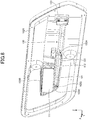
- FIG. 8 is a diagram illustrating the inner side of the second case 102B of the door handle apparatus 100 according to the embodiment.
- a holder portion 103C is formed on the inner surface of the second handle 103B of the second case 102B.
- the holder portion 103C has a through hole 103D that extends in the longitudinal direction (X-axis direction), and has a circular shape.
- the inner diameter of the through hole 103D is approximately the same as the outer diameter of the metal shaft 121.
- the metal shaft 121 passes through the through hole 103D, such that the holder portion 103C supports the front end portion of the metal shaft 121 with the outer peripheral surface of the metal shaft 121 contacting the inner peripheral surface of the through hole 103D. Accordingly, a force applied to the door handle 103 is transmitted to the front end portion of the metal shaft 121 through the holder portion 103C.
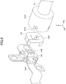
- FIG. 9 is a partially enlarged view of the metal shaft 121 according to the embodiment.
- a joint 121A having a circular tubular shape is provided at the rear end portion of the metal shaft 121.
- the joint 121A has a circular opening 121B on the side closer to the strain gauge 124.
- the strain gauge 124 having a circular shape is fitted into the opening 121B of the joint 121A. In this manner, the metal shaft 121 is connected to the strain gauge 124, thus allowing a force applied to the door handle 103 to be transmitted to the strain gauge 124.
- the force sensing unit 120 further includes an elastic member 125.
- the elastic member 125 is formed of an elastic material such as rubber or silicone.
- the elastic member 125 has a through hole 125A that extends in the longitudinal direction of the vehicle, and has a square shape.
- a projection 124B of the strain gauge 124 is fitted into the through hole 125A of the elastic member 125, and in this state, the elastic member 125 is fitted to the joint 121A together with the strain gauge 124. Accordingly, the force sensing unit 120 according to the present embodiment can transmit a force applied to the door handle 103 to the strain gauge 124 through the elastic member 125.
- the elastic member 125 of the force sensing unit 120 can reduce assembly error of the joint 121A of the metal shaft 121, displacement of the metal shaft 121 due to vibrations of the vehicle, excessive displacement of the metal shaft 121, and the like. Accordingly, the force sensing unit 120 according to the present embodiment can avoid excessive detection by the strain gauge 124. Note that if the strain gauge 124 is provided with a cap formed of an elastic material, the cap may be used as the elastic member 125.
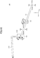
- FIG. 10 is a diagram illustrating the stress directions on the metal shaft 121.
- the middle portion of the metal shaft 121 is supported by the holder 122, and thus, the middle portion of the metal shaft 121 functions as a fulcrum. Therefore, upon a force being applied to the door handle 103, stress is applied to the front end portion of the metal shaft 121 (the portion on the front end side of the metal shaft 121 relative to the holder 122) in a direction same as the direction of the force applied to the door handle 103, and stress is applied to the rear end portion of the metal shaft 121 (portion on the rear end side of the metal shaft 121 relative to the holder 122) in a direction opposite to the direction of the force applied to the door handle 103.
- a force is applied to the door handle 103 in a direction toward the inside of the vehicle
- stress is applied to the front end portion of the metal shaft 121 (the portion on the front side of the metal shaft 121 relative to the holder 122) in a direction D1a toward the inside of the vehicle
- stress is applied to the rear end portion of the metal shaft 121 (the portion on the rear side of the metal shaft 121 relative to the holder 122) in a direction D1b toward the outside of the vehicle as illustrated in FIG. 10 .
- a strain is produced in the strain gauge 124 in the direction D1b.
- the strain gauge 124 outputs a force detection signal corresponding to the strain produced in the direction D1b. That is, the strain gauge 124 outputs a force detection signal indicating that the force is applied to the door handle 103 in the direction toward the inside of the vehicle.
- a force is applied to the door handle 103 in a direction toward the outside of the vehicle
- stress is applied to the front end portion of the metal shaft 121 (the portion on the front side of the metal shaft 121 relative to the holder 122) in a direction D2a toward the outside of the vehicle
- stress is applied to the rear end portion of the metal shaft 121 (the portion on the rear side of the metal shaft 121 relative to the holder 122) in a direction D2 toward the inside of the vehicle as illustrated in FIG. 10 .
- a strain is produced in the strain gauge 124 in the direction D2b.
- the strain gauge 124 outputs a force detection signal corresponding to the strain produced in the direction D2b. That is, the strain gauge 124 outputs a force detection signal indicating that the force is applied to the door handle 103 in the direction toward the outside of the vehicle.
- a force is applied to the door handle 103 in a downward direction
- stress is applied to the front end portion of the metal shaft 121 (the portion on the front side of the metal shaft 121 relative to the holder 122) in a downward direction D3a
- stress is applied to the rear end portion of the metal shaft 121 (the portion on the rear side of the metal shaft 121 relative to the holder 122) in an upward direction D3b as illustrated in FIG. 10 .
- a strain is produced in the strain gauge 124 in the upward direction D3b.
- the strain gauge 124 outputs a force detection signal corresponding to the strain produced in the upward direction D3b. That is, the strain gauge 124 outputs a force detection signal indicating that the force is applied to the door handle 103 in the downward direction.
- a force is applied to the door handle 103 in an upward direction
- stress is applied to the front end portion of the metal shaft 121 (the portion on the front side of the metal shaft 121 relative to the holder 122) in an upward direction D4a
- stress is applied to the rear end portion of the metal shaft 121 (the portion on the rear side of the metal shaft 121 relative to the holder 122) in a downward direction D4b as illustrated in FIG. 10 .
- a strain is produced in the strain gauge 124 in the downward direction D4b.
- the strain gauge 124 outputs a force detection signal corresponding to the strain produced in the downward direction D4b. That is, the strain gauge 124 outputs a force detection signal indicating that the force is applied to the door handle 103 in the upward direction.
- the force sensing unit 120 can adjust the detection sensitivity of the strain gauge 124 by changing the position of the holder 122 with respect to the metal shaft 121 (that is, position of the fulcrum of the metal shaft 121). For example, by providing the holder 122 at a position closer to the rear end of the metal shaft 121, the displacement of the rear end portion of the metal shaft 121 can be decreased. Accordingly, the detection sensitivity of the strain gauge 124 can be lowered. Conversely, by providing the holder 122 at a position closer to the front end of the metal shaft 121, the displacement of the rear end portion of the metal shaft 121 can be increased. Accordingly, the detection sensitivity of the strain gauge 124 can be enhanced.
- FIG. 11 is a block diagram illustrating a control configuration of the door handle apparatus 100 according to the embodiment.
- the control system 10 includes the door handle apparatus 100 and a control module 130.
- the control module 130 is an example of a "control means" and a "control apparatus".
- the control module 130 includes a first acquiring unit 131, a second acquiring unit 132, and a control unit 133.
- the first acquiring unit 131 acquires a first contact detection signal (a current value corresponding to the capacitance), indicating that the operation body has contacted the back side of the door handle 103, from the first capacitance sensor 111. Further, the first acquiring unit 131 acquires a second contact detection signal (a current value corresponding to the capacitance), indicating that the operation body has contacted the front side of the door handle 103, from the second capacitance sensor 112.
- the second acquiring unit 132 acquires a force detection signal (a voltage value corresponding to the direction of the strain and loads), indicating that a force is applied to the door handle 103 by the operation body, from the strain gauge 124.
- a force detection signal (a voltage value corresponding to the direction of the strain and loads), indicating that a force is applied to the door handle 103 by the operation body, from the strain gauge 124.
- the control unit 133 controls the opening/closing of the vehicle door and the operation (locking and unlocking) of the locking mechanism of the vehicle, based on the first contact detection signal and the second contact detection signal acquired by the first acquiring unit 131 and the force detection signal acquired by the second acquiring unit 132.
- the control unit 133 controls the opening/closing of the vehicle door and the operation (locking and unlocking) of the locking mechanism of the vehicle in accordance with the direction of a force applied to the door handle 103 identified by the force detection signal.
- control unit 133 controls the opening/closing of the vehicle door and the operation (locking and unlocking) of the locking mechanism of the vehicle, when the user's hand contacts both sides (the front and back sides) of the door handle 103 and also a force is applied by the user's hand to the door handle 103.
- the control unit 133 controls the opening of the vehicle door. For example, when the vehicle door is closed, the control unit 133 performs control such that the vehicle door automatically opens. Further, for example, when the vehicle door is automatically closing, the control unit 133 performs control such that the closing of the door is stopped.
- the control unit 133 controls the closing of the vehicle door. For example, when the vehicle door is open, the control unit 133 performs control such that the vehicle door is automatically closed. Further, for example, when the vehicle door is automatically opening, the control unit 133 performs control such that the opening of the door is stopped.
- control unit 133 may include a control section (not illustrated) configured to control a door opening and closing mechanism (such as a motor), and the control unit 133 may cause the control section to control the door opening and closing by transmitting a control signal to the control section.
- control unit 133 may directly control the opening and closing of the door by transmitting a control signal to the door opening and closing mechanism.
- the control unit 133 performs control for locking the locking mechanism of the vehicle. For example, when the locking mechanism of the vehicle is unlocked, the control unit 133 performs control such that the locking mechanism of the vehicle is automatically locked.
- the control unit 133 performs control for unlocking the locking mechanism of the vehicle. For example, when the locking mechanism of the vehicle is locked, the control unit 133 performs control such that the locking mechanism of the vehicle is automatically unlocked.
- control unit 133 may include a control section (not illustrated) configured to control the locking mechanism (such as a motor), and the control unit 133 may cause the control section to control the locking mechanism of the vehicle by transmitting a control signal to the control section.
- control unit 133 may directly control the operation of the locking mechanism of the vehicle by transmitting a control signal to the locking mechanism of the vehicle.
- each of the first capacitance sensor 111 and the second capacitance sensor 112 includes a plurality of (four, for example) detection electrodes that are arranged in the longitudinal direction of the vehicle, and each of the detection electrodes is configured to output a contact detection signal.
- control unit 133 may control the opening or closing of the door or the operation (locking or unlocking) of the locking mechanism of the vehicle, when first contact detection signals are acquired from a predetermined number or more (two or more, for example) of detection electrodes of the first capacitance sensor 111, second contact detection signals are acquired from a predetermined number or more (two or more, for example) of detection electrodes of the second capacitance sensor 112, and a force detection signal is acquired from the strain gauge 124.
- the control unit 133 may perform other control (such as controlling a power window) instead of controlling the locking mechanism of the vehicle. For example, if the strain gauge 124 detects that a force is applied to the door handle 103 in the upward direction, the control unit 133 may control the closing of the power window. Conversely, if the strain gauge 124 detects that a force is applied to the door handle 103 in the downward direction, the control unit 133 may control the opening of the power window.
- control module 130 includes a central processing unit (CPU), a read-only memory (ROM), a random-access memory (RAM), and an external interface (I/F).
- CPU central processing unit
- ROM read-only memory
- RAM random-access memory
- I/F external interface
- the control module 130 may implement the functions illustrated in FIG. 11 by causing the CPU to execute a program stored in the ROM.
- the control module 130 may be a microcomputer.
- FIG. 12 is a flowchart of a process performed by the control module 130 according to the embodiment.
- control module 130 determines whether the first acquiring unit 131 has acquired a first contact detection signal from the first capacitance sensor 111 (step S201). In step S201, if the control module 130 determines that a first contact detection signal has not been acquired (no in step S201), the control module 130 ends the process illustrated in FIG. 12 .
- step S201 determines whether the first acquiring unit 131 has acquired a second contact detection signal from the second capacitance sensor 112 (step S202).
- step S202 if the control module 130 determines that a second contact detection signal has not been acquired (no in step S202), the control module 130 ends the process illustrated in FIG. 12 .
- step S202 if the control module 130 determines that a second contact detection signal has been acquired (yes in step S202), the control module 130 determines whether the second acquiring unit 132 has acquired a force detection signal from the strain gauge 124 (step S203). In step S203, if the control module 130 determines that a force detection signal has not been acquired (no in step S203), the control module 130 ends the process illustrated in FIG. 12 .
- step S203 if the control module 130 determines that a force detection signal has been acquired (yes in step S203), the control unit 133 determines whether the direction of a force applied to the door handle 103 is the direction toward the outside of the vehicle, based on the force detection signal acquired by the second acquiring unit 132 (step S204).
- step S204 if the control unit 133 determines that the direction of the force applied to the door handle 103 is the direction toward the outside of the vehicle (yes in step S204), the control unit 133 controls the opening of the vehicle door (step S205). Then, the control module 130 ends the process illustrated in FIG. 12 .
- step S204 if the control unit 133 determines that the direction of the force applied to the door handle 103 is not the direction toward the outside of the vehicle (no in step S204), the control unit 133 determines whether the direction of the force applied to the door handle 103 is the direction toward the inside of the vehicle, based on the force detection signal acquired by the second acquiring unit 132 (step S206).
- step S206 if the control unit 133 determines that the direction of the force applied to the door handle 103 is the direction toward the inside of the vehicle (yes in step S206), the control unit 133 controls the closing of the vehicle door (step S207). Then, the control module 130 ends the process illustrated in FIG. 12 .
- step S206 if the control unit 133 determines that the direction of the force applied to the door handle 103 is not the direction toward the inside of the vehicle (no in step S206), the control unit 133 determines whether the direction of the force applied to the door handle 103 is the downward direction (step S208).
- step S208 if the control unit 133 determines that the direction of the force applied to the door handle 103 is the downward direction (yes in step S208), the control unit 133 controls locking of the vehicle door (step S209). Then, the control module 130 ends the process illustrated in FIG. 12 .
- step S208 if the control unit 133 determines that the direction of the force applied to the door handle 103 is not the downward direction (no in step S208), the control unit 133 determines whether the direction of the force applied to the door handle 103 is the upward direction (step S210).
- step S210 if the control unit 133 determines that the direction of the force applied to the door handle 103 is the upward direction (yes in step S210), the control unit 133 controls the unlocking of the vehicle door (step S211). Then, the control module 130 ends the process illustrated in FIG. 12 .
- step S210 if the control unit 133 determines that the direction of the force applied to the door handle 103 is not the upward direction (no in step S210), the control module 130 ends the process illustrated in FIG. 12 .
- the control system 10 includes the contact sensing unit 110 configured to detect contact between a user's hand (an operation body) and the door handle 103, the strain gauge 124 configured to detect a force applied by the user's hand (the operation body) to the door handle 103, and the control module 130 configured to control the opening or closing of a door when the contact applied to door handle 103 is detected by the contact sensing unit 110 and the force applied to the door handle 103 is detected by the strain gauge 124. Accordingly, if the door handle 103 is unintentionally touched, the control system 10 according to the present embodiment does not perform the opening or closing of the door unless the force applied to the door handle 103 is detected at the same time. Therefore, the control system 10 according to the present embodiment can avoid an unintended opening/closing operation of the door.
- the control system 10 includes the rod-shaped metal shaft 121.
- the rod-shaped metal shaft 121 is disposed in the door handle 103, includes the holder 122 (fulcrum) between one end portion and the other end portion of the metal shaft 121, and transmits the force from the one end portion to the other end portion.
- the strain gauge 124 detects the force transmitted to the other end portion of the metal shaft 121. Accordingly, although the door handle 103 is not configured to be movable, the control system 10 according to the present embodiment can securely detect the force applied to the door handle 103.
- control system 10 can readily and appropriately adjust the detection sensitivity of the strain gauge 124 in accordance with the required specifications by changing the design of the metal shaft 121 (such as the length, the diameter, the position of the fulcrum, or the material) of the metal shaft 121.
- the contact sensing unit 110 includes the first capacitance sensor 111 disposed on the back side of the door handle 103 and the second capacitance sensor 112 disposed on the front side of the door handle 103.
- the control module 130 controls the opening or closing of the door when the contact with the door handle 103 is detected by the first capacitance sensor 111 and by the second capacitance sensor 112 and the force applied to the door handle 103 is detected by the strain gauge 124. Accordingly, the control system 10 according to the present embodiment controls the opening or closing of the door when the user holds the door handle 103 and the contact between the user and the door handle 103 is detected by both the first capacitance sensor 111 and the second capacitance sensor 112.
- control system 10 does not perform the opening or closing of the door when the contact between the user and the door handle 103 is detected by either the first capacitance sensor 111 or the second capacitance sensor 112. Accordingly, the control system 10 according to the present embodiment can avoid an unintended opening and closing operation of the door.
- control module 13 controls the opening of the door when the strain gauge 124 detects a force applied to the door handle 103 in the direction toward the outside of the vehicle (a force in a first direction corresponding to the direction of opening the door).
- control module 130 controls the closing of the door when the strain gauge 124 detects a force in the direction toward the inside of the vehicle (a force in a second direction corresponding to the direction of closing the door). Accordingly, the control system 10 according to the present embodiment can control the opening or closing of the door in accordance with the user's intuitive operation with respect to the door handle 103.
- the strain gauge 124 can detect a force applied to the door handle 103 in the vertical direction of the vehicle.
- the control module 130 can control the locking and unlocking the door. Accordingly, with a relatively simple configuration, the control system 10 according to the present embodiment can detect the user's operations for opening/closing the door and also for locking/unlocking the door, and can control the opening/closing of the door and also the locking/unlocking of the door.
- the door handle 103 extends in the longitudinal direction of the vehicle and the rear end portion of the door handle 103 is connected to the door handle case 102; however, the present invention is not limited thereto.
- a door handle whose front end portion is connected to the door handle case, a door handle whose front end portion and rear end portion are connected to the door handle case, or a door handle extending in the vertical direction of the vehicle may be used.
- the present invention can be applied to a hinged door, a sliding door, a gull-wing door, and a door of any other type. Further, the present invention can be applied to a door handle inside the vehicle and a door handle outside the vehicle.
- the present invention can be applied to any door other than the vehicle door.
- a door handle that extends in the vertical direction of the vehicle may be used for a sliding door that slides backward.
- the opening of the sliding door may be controlled, and when a force in the forward direction is detected, the closing of the sliding door may be controlled.
- two force sensing units 120 may be vertically arranged in parallel.
- the control unit 133 may detect the twisting of the door handle 103 based on a force detection signal output from a strain gauge 124 (a first strain gauge) of one of the force sensing units 120 and a force detection signal output from a strain gauge 124 (a second strain gauge) of the other force sensing unit 120. Then, if the twisting of the door handle 103 is detected, the control unit 133 may control the vehicle door (such as controlling the locking mechanism or controlling a power window).
- the force detection signal output from the one force sensing unit 120 and the force detection signal output from the other force sensing unit 120 indicate different horizontal directions. Therefore, if the second acquiring unit 132 acquires force detection signals indicating different directions, the twisting of the door handle 103 can be detected.
- control system 10 may further include an authentication means that uses a known authentication method to authenticate a smart key possessed by a user.
- control unit 133 may control the door when the contact with the door handle 103 is detected, the force applied to the door handle 103 is detected, and the smart key is successfully authenticated by the authentication means.
- control system 10 may further include a communication means configured to notify the user that the opening/closing of the door starts to be controlled by sound, light, or vibration when the control system 10 starts to control the opening/closing of the door.
Landscapes
- Engineering & Computer Science (AREA)
- Computer Networks & Wireless Communication (AREA)
- Lock And Its Accessories (AREA)
- Power-Operated Mechanisms For Wings (AREA)
Abstract
Description
- The present invention relates to a control system, a door handle apparatus, a control apparatus, and a control method.
- Conventionally, there is known a technology in which a sensor detects contact between a user and of a vehicle, and the operation of a door of the vehicle is controlled in accordance with a detection signal output from the sensor.
- For example, Patent Document 1 describes a technology in which an in-vehicle unit controls the opening of a sliding door of a vehicle when contact between a user and a door handle of the sliding door is detected by a touch sensor installed on the door handle.
- Further, Patent Document 2 describes a technology in which a control apparatus locks or unlocks a vehicle when contact between a user's finger and a door handle of the vehicle is detected by a capacitive sensor installed on the door handle.
-
- Patent Document 1:
Japanese Laid-Open Patent Publication No. 2007-23620 - Patent Document 2:
Japanese Laid-Open Patent Publication No. 2013-511635 - However, in the technology described in Patent Document 1, the sliding door of the vehicle may malfunction if the touch sensor detects the user's unintended contact.
- According to an embodiment, a control system includes a contact sensing means configured to detect contact between an operation body and a door handle, a force sensing means configured to detect a force applied by the operation body to the door handle, and a control means configured to control opening or closing of a door when the contact is detected by the contact sensing means and the force is detected by the force sensing means.
- According to an embodiment, a control system capable of controlling the opening and closing of a door based on information from sensors in order to avoid an unintended opening/closing operation of the door is provided.
-
-
FIG. 1 is a perspective view of the exterior of a door handle apparatus according to an embodiment; -
FIG. 2 is a front view of the door handle apparatus according to the embodiment; -
FIG. 3 is a rear view of the door handle apparatus according to the embodiment; -
FIG. 4 is a top view of the door handle apparatus according to the embodiment; -
FIG. 5 is a perspective view of the exterior of the door handle apparatus (from which a second case is removed) according to the embodiment; -
FIG. 6 is a front view of the door handle apparatus (from which the second case is removed) according to the embodiment; -
FIG. 7 is a perspective view of the door handle apparatus (from which the second case is removed) as viewed from the front according to the embodiment; -
FIG. 8 is a diagram illustrating the inner side of the second case of the door handle apparatus according to the embodiment; -
FIG. 9 is a partially enlarged view of a metal shaft according to the embodiment; -
FIG. 10 is a diagram illustrating the stress directions on the metal shaft according to the embodiment; -
FIG. 11 is a block diagram illustrating a control configuration of the door handle apparatus according to the embodiment; and -
FIG. 12 is a flowchart of a process performed by a control module according to the embodiment. - In the following, embodiments will be described with reference to the accompanying drawings.
-
FIG. 1 is a perspective view of the exterior of adoor handle apparatus 100 according to an embodiment.FIG. 2 is a front view of thedoor handle apparatus 100 according to the embodiment.FIG. 3 is a rear view of thedoor handle apparatus 100 according to the embodiment.FIG. 4 is a top view of thedoor handle apparatus 100 according to the embodiment. - In the drawings, for the sake of convenience, a Z-axis direction (corresponding to the height direction of a vehicle) is referred to as a vertical direction, a Y-axis direction (corresponding to the width direction of the vehicle) is referred to as a lateral direction, and an X-axis direction (corresponding to the lengthwise direction of the vehicle) is referred to as a longitudinal direction.
- The
door handle apparatus 100 illustrated inFIG. 1 through FIG. 4 is integrally formed with an inner panel (not illustrated) of a vehicle door by being fitted into an opening, having approximately the same shape as thedoor handle apparatus 100, of the inner panel, and is used to allow a user to open/close the vehicle door. - As illustrated in
FIG. 1 through FIG. 4 , thedoor handle apparatus 100 includes abody 100A. Thebody 100A forms the external shape of thedoor handle apparatus 100. For example, thebody 100A may be formed of a resin material such as an acrylonitrile butadiene styrene (ABS) resin or a polycarbonate (PC) resin. Thebody 100A includes abase plate 101, adoor handle case 102, and adoor handle 103, which are integrally formed. - The
base plate 101 has a flat plate shape. Further, thebase plate 101 supports thedoor handle case 102 and thedoor handle 103, and is fixed to the vehicle door. Thedoor handle case 102 has a flat plate shape. Further, thedoor handle case 102 is disposed closer to the inside of the vehicle than thebase plate 101, and is coupled to thebase plate 101. Thedoor handle case 102 is exposed to the inside of the vehicle with thedoor handle apparatus 100 being fitted into the inner panel of the vehicle door. - The
door handle 103 has a hollow plate shape and extends linearly in the longitudinal direction (the X-axis direction). Thedoor handle 103 is held by the user's hand when the user performs operations (such as opening/closing of the vehicle door and locking/unlocking of a locking mechanism of the vehicle). The rear end portion (the end portion on the negative X-side) of thedoor handle 103 is connected to thedoor handle case 102, and is integrally formed with thedoor handle case 102. Thedoor handle 103 is not movable and is configured to slightly bend and deform in response to an operating force being applied by the user. - The
body 100A has arecess 104 that is recessed toward the outside of the vehicle (toward the negative Y-side) in the surroundings of thedoor handle 103. With this configuration, thedoor handle apparatus 100 allows the user to reach the back side of thedoor handle 103. Accordingly, both the front side (closer to the inside of the vehicle) and the back side (closer to the outside of the vehicle) of thedoor handle 103 can be readily held by the user's hand. -
FIG. 5 is a perspective view of the exterior of the door handle apparatus 100 (from which asecond case 102B is removed) according to the embodiment.FIG. 6 is a front view of the door handle apparatus 100 (from which thesecond case 102B is removed) according to the embodiment.FIG. 7 is a perspective view of the door handle apparatus 100 (from which thesecond case 102B is removed) as viewed from the front according to the embodiment. - As illustrated in
FIG. 5 , thedoor handle case 102 of thebody 100A can be divided into afirst case 102A disposed closer to the outside of the vehicle, and thesecond case 102B disposed closer to the inside of the vehicle. Thefirst case 102A is fixed to thebase plate 101. Further, thedoor handle case 102 has a hollow structure. As illustrated inFIG. 5 , the interior of thedoor handle case 102 can be exposed by removing thesecond case 102B from thefirst case 102A. - The
door handle 103 is provided across thefirst case 102A and thesecond case 102B. Therefore, as illustrated inFIG. 5 , when thedoor handle case 102 is divided into thefirst case 102A and thesecond case 102B, thedoor handle 103 can be divided into afirst handle 103A that is integrally formed with thefirst case 102A, and asecond handle 103B that is integrally formed with thesecond case 102B. - As illustrated in
FIG. 5 through FIG. 7 , acontact sensing unit 110 and aforce sensing unit 120 are provided in the interior of thedoor handle case 102. - The
contact sensing unit 110 is an example of a "contact sensing means". Thecontact sensing unit 110 includes afirst capacitance sensor 111 and asecond capacitance sensor 112. Each of thefirst capacitance sensor 111 and thesecond capacitance sensor 112 is a thin, flat, rectangular shape and is elongated as viewed in the Y-axis direction in planar view. Thefirst capacitance sensor 111 is stacked on thesecond capacitance sensor 112 in the Y-axis direction within thedoor handle 103. - The
first capacitance sensor 111 is an example of a "first contact sensor". Thefirst capacitance sensor 111 is disposed on the back side (on the negative Y-side) of thedoor handle 103, and is configured to detect contact of an operation body with the back side of thedoor handle 103. Specifically, thefirst capacitance sensor 111 includes detection electrodes, and upon the operation body contacting the back side of thedoor handle 103, thefirst capacitance sensor 111 outputs a current value corresponding to the capacitance between the operation body and each of the detection electrodes as a first contact detection signal. - The
second capacitance sensor 112 is an example of a "second contact sensor". Thesecond capacitance sensor 112 is disposed on the front side (on the positive Y-side) of thedoor handle 103, and detects contact of the operation body with the front side of thedoor handle 103. Specifically, thesecond capacitance sensor 112 includes detection electrodes, and upon the operation body contacting the front side of thedoor handle 103, thesecond capacitance sensor 112 outputs a current value corresponding to the capacitance between the operation body and each of the detection electrodes as a second contact detection signal. - The
force sensing unit 120 includes ametal shaft 121, aholder 122, asensor base 123, and astrain gauge 124. Thestrain gauge 124 is connected to the rear end portion of themetal shaft 121. Note that thestrain gauge 124 is difficult to be seen from the outside, and is indicated by a hidden line inFIG. 7 . A configuration of thestrain gauge 124 will be described later in detail with reference toFIG. 9 . - The
metal shaft 121 is an example of a "transmitting means". Themetal shaft 121 is made of metal and has a rod shape. Themetal shaft 121 extends linearly in the longitudinal direction (in the X-axis direction) within thedoor handle case 102. Themetal shaft 121 is configured to transmit a force applied to thedoor handle 103 to thestrain gauge 124. A middle portion of themetal shaft 121 is supported by theholder 122, and a front end portion (on the positive X-side) of themetal shaft 121, located on the front side of the vehicle relative to the middle portion, is disposed within thedoor handle 103. Accordingly, the force applied to thedoor handle 103 is transmitted to the front end portion of themetal shaft 121, and stress occurs in the front end portion of themetal shaft 121. The stress occurring in the front end portion of themetal shaft 121 is transmitted to the rear end portion of themetal shaft 121 through a fulcrum (the holder 122). The stress transmitted to the rear end portion of themetal shaft 121 is further transmitted to thestrain gauge 124 that is connected to the rear end portion of themetal shaft 121. In the present embodiment, themetal shaft 121 is a round bar, but the present invention is not limited thereto. - The
holder 122 supports the middle portion of themetal shaft 121 and thus functions as a fulcrum. Specifically, as illustrated inFIG. 8 , theholder 122 is fixed to the inner surface of thesecond case 102B (at a position in the vicinity of the rear end portion of thesecond handle 103B). As illustrated inFIG. 7 andFIG. 8 , theholder 122 has a throughhole 122A that extends in the longitudinal direction (X-axis direction), and has a circular shape. The inner diameter of the throughhole 122A is approximately the same as the outer diameter of themetal shaft 121. Further, as illustrated inFIG. 5 through FIG. 8 , themetal shaft 121 passes through the throughhole 122A, such that theholder 122 supports the middle portion of themetal shaft 121 with the outer peripheral surface of themetal shaft 121 contacting the inner peripheral surface of the throughhole 122A. In this manner, theholder 122 can support the middle portion of themetal shaft 121 without looseness of themetal shaft 121. - The
sensor base 123 is a member that supports thestrain gauge 124. Specifically, as illustrated inFIG. 8 , thesensor base 123 is fixed to the inner surface of thesecond case 102B at a position behind the rear end portion (the end portion on the negative X side) of themetal shaft 121. Asurface 123A of thesensor base 123 faces the rear end of themetal shaft 121, and thestrain gauge 124 is screwed to thesurface 123A. Accordingly, thesensor base 123 supports thestrain gauge 124, such that thestrain gauge 124 is connected to the rear end portion of themetal shaft 121 and can detect stress transmitted to the rear end portion of themetal shaft 121. - The
strain gauge 124 is an example of a "force sensing means". Thestrain gauge 124 detects a force applied to thedoor handle 103. Specifically, thestrain gauge 124 is disposed facing the rear end portion of themetal shaft 121. When the force is applied to thedoor handle 103, thestrain gauge 124 is subjected to stress transmitted from the rear end portion of themetal shaft 121. As a result, a strain is applied to a metallic resistance material of thestrain gauge 124, thus causing the resistance value to change. Accordingly, thestrain gauge 124 outputs a voltage value corresponding to the direction of the strain and loads applied to thestrain gauge 124, via a flexible printed circuit (FPC) 124A. That is, thestrain gauge 124 outputs a force detection signal that indicates the force applied to thedoor handle 103. Note that thestrain gauge 124 can detect strains in the Y-axis direction and in the Z-axis direction. Therefore, thestrain gauge 124 can detect a force applied to thedoor handle 103 in the Y-axis direction (which corresponds to the lateral direction of the vehicle, and is an example of a "first direction" and a "second direction"), and a force applied to thedoor handle 103 in the Z-axis direction (which corresponds to the vertical direction of the vehicle, and is an example of a "third direction"). Thestrain gauge 124 may have a structure similar to that of a pointing stick, for example. -
FIG. 8 is a diagram illustrating the inner side of thesecond case 102B of thedoor handle apparatus 100 according to the embodiment. As illustrated inFIG. 8 , aholder portion 103C is formed on the inner surface of thesecond handle 103B of thesecond case 102B. Theholder portion 103C has a throughhole 103D that extends in the longitudinal direction (X-axis direction), and has a circular shape. The inner diameter of the throughhole 103D is approximately the same as the outer diameter of themetal shaft 121. Themetal shaft 121 passes through the throughhole 103D, such that theholder portion 103C supports the front end portion of themetal shaft 121 with the outer peripheral surface of themetal shaft 121 contacting the inner peripheral surface of the throughhole 103D. Accordingly, a force applied to thedoor handle 103 is transmitted to the front end portion of themetal shaft 121 through theholder portion 103C. -
FIG. 9 is a partially enlarged view of themetal shaft 121 according to the embodiment. As illustrated inFIG. 9 , a joint 121A having a circular tubular shape is provided at the rear end portion of themetal shaft 121. The joint 121A has acircular opening 121B on the side closer to thestrain gauge 124. Thestrain gauge 124 having a circular shape is fitted into theopening 121B of the joint 121A. In this manner, themetal shaft 121 is connected to thestrain gauge 124, thus allowing a force applied to thedoor handle 103 to be transmitted to thestrain gauge 124. - As illustrated in
FIG. 9 , theforce sensing unit 120 according to the present embodiment further includes anelastic member 125. Theelastic member 125 is formed of an elastic material such as rubber or silicone. Theelastic member 125 has a throughhole 125A that extends in the longitudinal direction of the vehicle, and has a square shape. Aprojection 124B of thestrain gauge 124 is fitted into the throughhole 125A of theelastic member 125, and in this state, theelastic member 125 is fitted to the joint 121A together with thestrain gauge 124. Accordingly, theforce sensing unit 120 according to the present embodiment can transmit a force applied to thedoor handle 103 to thestrain gauge 124 through theelastic member 125. With this configuration, theelastic member 125 of theforce sensing unit 120 according to the present embodiment can reduce assembly error of the joint 121A of themetal shaft 121, displacement of themetal shaft 121 due to vibrations of the vehicle, excessive displacement of themetal shaft 121, and the like. Accordingly, theforce sensing unit 120 according to the present embodiment can avoid excessive detection by thestrain gauge 124. Note that if thestrain gauge 124 is provided with a cap formed of an elastic material, the cap may be used as theelastic member 125. -
FIG. 10 is a diagram illustrating the stress directions on themetal shaft 121. As illustrated inFIG. 10 , the middle portion of themetal shaft 121 is supported by theholder 122, and thus, the middle portion of themetal shaft 121 functions as a fulcrum. Therefore, upon a force being applied to thedoor handle 103, stress is applied to the front end portion of the metal shaft 121 (the portion on the front end side of themetal shaft 121 relative to the holder 122) in a direction same as the direction of the force applied to thedoor handle 103, and stress is applied to the rear end portion of the metal shaft 121 (portion on the rear end side of themetal shaft 121 relative to the holder 122) in a direction opposite to the direction of the force applied to thedoor handle 103. - For example, when a force is applied to the
door handle 103 in a direction toward the inside of the vehicle, stress is applied to the front end portion of the metal shaft 121 (the portion on the front side of themetal shaft 121 relative to the holder 122) in a direction D1a toward the inside of the vehicle, and stress is applied to the rear end portion of the metal shaft 121 (the portion on the rear side of themetal shaft 121 relative to the holder 122) in a direction D1b toward the outside of the vehicle as illustrated inFIG. 10 . In this case, a strain is produced in thestrain gauge 124 in the direction D1b. Accordingly, thestrain gauge 124 outputs a force detection signal corresponding to the strain produced in the direction D1b. That is, thestrain gauge 124 outputs a force detection signal indicating that the force is applied to thedoor handle 103 in the direction toward the inside of the vehicle. - Further, when a force is applied to the
door handle 103 in a direction toward the outside of the vehicle, stress is applied to the front end portion of the metal shaft 121 (the portion on the front side of themetal shaft 121 relative to the holder 122) in a direction D2a toward the outside of the vehicle, and stress is applied to the rear end portion of the metal shaft 121 (the portion on the rear side of themetal shaft 121 relative to the holder 122) in a direction D2 toward the inside of the vehicle as illustrated inFIG. 10 . In this case, a strain is produced in thestrain gauge 124 in the direction D2b. Accordingly, thestrain gauge 124 outputs a force detection signal corresponding to the strain produced in the direction D2b. That is, thestrain gauge 124 outputs a force detection signal indicating that the force is applied to thedoor handle 103 in the direction toward the outside of the vehicle. - Further, when a force is applied to the
door handle 103 in a downward direction, stress is applied to the front end portion of the metal shaft 121 (the portion on the front side of themetal shaft 121 relative to the holder 122) in a downward direction D3a, and stress is applied to the rear end portion of the metal shaft 121 (the portion on the rear side of themetal shaft 121 relative to the holder 122) in an upward direction D3b as illustrated inFIG. 10 . In this case, a strain is produced in thestrain gauge 124 in the upward direction D3b. Accordingly, thestrain gauge 124 outputs a force detection signal corresponding to the strain produced in the upward direction D3b. That is, thestrain gauge 124 outputs a force detection signal indicating that the force is applied to thedoor handle 103 in the downward direction. - Further, when a force is applied to the
door handle 103 in an upward direction, stress is applied to the front end portion of the metal shaft 121 (the portion on the front side of themetal shaft 121 relative to the holder 122) in an upward direction D4a, and stress is applied to the rear end portion of the metal shaft 121 (the portion on the rear side of themetal shaft 121 relative to the holder 122) in a downward direction D4b as illustrated inFIG. 10 . In this case, a strain is produced in thestrain gauge 124 in the downward direction D4b. Accordingly, thestrain gauge 124 outputs a force detection signal corresponding to the strain produced in the downward direction D4b. That is, thestrain gauge 124 outputs a force detection signal indicating that the force is applied to thedoor handle 103 in the upward direction. - The
force sensing unit 120 according to the present embodiment can adjust the detection sensitivity of thestrain gauge 124 by changing the position of theholder 122 with respect to the metal shaft 121 (that is, position of the fulcrum of the metal shaft 121). For example, by providing theholder 122 at a position closer to the rear end of themetal shaft 121, the displacement of the rear end portion of themetal shaft 121 can be decreased. Accordingly, the detection sensitivity of thestrain gauge 124 can be lowered. Conversely, by providing theholder 122 at a position closer to the front end of themetal shaft 121, the displacement of the rear end portion of themetal shaft 121 can be increased. Accordingly, the detection sensitivity of thestrain gauge 124 can be enhanced. -
FIG. 11 is a block diagram illustrating a control configuration of thedoor handle apparatus 100 according to the embodiment. As illustrated inFIG. 11 , thecontrol system 10 includes thedoor handle apparatus 100 and acontrol module 130. - The
control module 130 is an example of a "control means" and a "control apparatus". Thecontrol module 130 includes a first acquiringunit 131, a second acquiringunit 132, and acontrol unit 133. - The first acquiring
unit 131 acquires a first contact detection signal (a current value corresponding to the capacitance), indicating that the operation body has contacted the back side of thedoor handle 103, from thefirst capacitance sensor 111. Further, the first acquiringunit 131 acquires a second contact detection signal (a current value corresponding to the capacitance), indicating that the operation body has contacted the front side of thedoor handle 103, from thesecond capacitance sensor 112. - The second acquiring
unit 132 acquires a force detection signal (a voltage value corresponding to the direction of the strain and loads), indicating that a force is applied to thedoor handle 103 by the operation body, from thestrain gauge 124. - The
control unit 133 controls the opening/closing of the vehicle door and the operation (locking and unlocking) of the locking mechanism of the vehicle, based on the first contact detection signal and the second contact detection signal acquired by the first acquiringunit 131 and the force detection signal acquired by the second acquiringunit 132. - Specifically, when the first contact detection signal and the second contact detection signal are acquired by the first acquiring
unit 131 and also the force detection signal is acquired by the second acquiringunit 132, thecontrol unit 133 controls the opening/closing of the vehicle door and the operation (locking and unlocking) of the locking mechanism of the vehicle in accordance with the direction of a force applied to thedoor handle 103 identified by the force detection signal. - That is, the
control unit 133 controls the opening/closing of the vehicle door and the operation (locking and unlocking) of the locking mechanism of the vehicle, when the user's hand contacts both sides (the front and back sides) of thedoor handle 103 and also a force is applied by the user's hand to thedoor handle 103. - For example, if the direction of the force applied to the
door handle 103 identified by the force detection signal is the direction toward the outside of the vehicle (the negative Y-direction), thecontrol unit 133 controls the opening of the vehicle door. For example, when the vehicle door is closed, thecontrol unit 133 performs control such that the vehicle door automatically opens. Further, for example, when the vehicle door is automatically closing, thecontrol unit 133 performs control such that the closing of the door is stopped. - Further, if the direction of the force applied to the
door handle 103 identified by the force detection signal is the direction toward the inside of the vehicle (the positive Y-direction), thecontrol unit 133 controls the closing of the vehicle door. For example, when the vehicle door is open, thecontrol unit 133 performs control such that the vehicle door is automatically closed. Further, for example, when the vehicle door is automatically opening, thecontrol unit 133 performs control such that the opening of the door is stopped. - For example, the
control unit 133 may include a control section (not illustrated) configured to control a door opening and closing mechanism (such as a motor), and thecontrol unit 133 may cause the control section to control the door opening and closing by transmitting a control signal to the control section. However, the present invention is not limited thereto, and thecontrol unit 133 may directly control the opening and closing of the door by transmitting a control signal to the door opening and closing mechanism. - Further, if the direction of the force applied to the
door handle 103 identified by the force detection signal is the downward direction (the negative Z-direction), thecontrol unit 133 performs control for locking the locking mechanism of the vehicle. For example, when the locking mechanism of the vehicle is unlocked, thecontrol unit 133 performs control such that the locking mechanism of the vehicle is automatically locked. - Further, if the direction of the force applied to the
door handle 103 identified by the force detection signal is the upward direction (the positive Z-direction), thecontrol unit 133 performs control for unlocking the locking mechanism of the vehicle. For example, when the locking mechanism of the vehicle is locked, thecontrol unit 133 performs control such that the locking mechanism of the vehicle is automatically unlocked. - For example, the
control unit 133 may include a control section (not illustrated) configured to control the locking mechanism (such as a motor), and thecontrol unit 133 may cause the control section to control the locking mechanism of the vehicle by transmitting a control signal to the control section. However, the present invention is not limited thereto, and thecontrol unit 133 may directly control the operation of the locking mechanism of the vehicle by transmitting a control signal to the locking mechanism of the vehicle. - In the
door handle apparatus 100 according to the present embodiment, each of thefirst capacitance sensor 111 and thesecond capacitance sensor 112 includes a plurality of (four, for example) detection electrodes that are arranged in the longitudinal direction of the vehicle, and each of the detection electrodes is configured to output a contact detection signal. For example, thecontrol unit 133 may control the opening or closing of the door or the operation (locking or unlocking) of the locking mechanism of the vehicle, when first contact detection signals are acquired from a predetermined number or more (two or more, for example) of detection electrodes of thefirst capacitance sensor 111, second contact detection signals are acquired from a predetermined number or more (two or more, for example) of detection electrodes of thesecond capacitance sensor 112, and a force detection signal is acquired from thestrain gauge 124. - Further, if the
strain gauge 124 detects that a force is applied to thedoor handle 103 in the vertical direction of the vehicle, thecontrol unit 133 may perform other control (such as controlling a power window) instead of controlling the locking mechanism of the vehicle. For example, if thestrain gauge 124 detects that a force is applied to thedoor handle 103 in the upward direction, thecontrol unit 133 may control the closing of the power window. Conversely, if thestrain gauge 124 detects that a force is applied to thedoor handle 103 in the downward direction, thecontrol unit 133 may control the opening of the power window. - For example, the
control module 130 includes a central processing unit (CPU), a read-only memory (ROM), a random-access memory (RAM), and an external interface (I/F). For example, thecontrol module 130 may implement the functions illustrated inFIG. 11 by causing the CPU to execute a program stored in the ROM. Thecontrol module 130 may be a microcomputer. -
FIG. 12 is a flowchart of a process performed by thecontrol module 130 according to the embodiment. - First, the
control module 130 determines whether the first acquiringunit 131 has acquired a first contact detection signal from the first capacitance sensor 111 (step S201). In step S201, if thecontrol module 130 determines that a first contact detection signal has not been acquired (no in step S201), thecontrol module 130 ends the process illustrated inFIG. 12 . - Conversely, if the
control module 130 determines that a first contact detection signal has been acquired (yes in step S201), thecontrol module 130 determines whether the first acquiringunit 131 has acquired a second contact detection signal from the second capacitance sensor 112 (step S202). In step S202, if thecontrol module 130 determines that a second contact detection signal has not been acquired (no in step S202), thecontrol module 130 ends the process illustrated inFIG. 12 . - Conversely, in step S202, if the
control module 130 determines that a second contact detection signal has been acquired (yes in step S202), thecontrol module 130 determines whether the second acquiringunit 132 has acquired a force detection signal from the strain gauge 124 (step S203). In step S203, if thecontrol module 130 determines that a force detection signal has not been acquired (no in step S203), thecontrol module 130 ends the process illustrated inFIG. 12 . - Conversely, in step S203, if the
control module 130 determines that a force detection signal has been acquired (yes in step S203), thecontrol unit 133 determines whether the direction of a force applied to thedoor handle 103 is the direction toward the outside of the vehicle, based on the force detection signal acquired by the second acquiring unit 132 (step S204). - In step S204, if the
control unit 133 determines that the direction of the force applied to thedoor handle 103 is the direction toward the outside of the vehicle (yes in step S204), thecontrol unit 133 controls the opening of the vehicle door (step S205). Then, thecontrol module 130 ends the process illustrated inFIG. 12 . - In step S204, if the
control unit 133 determines that the direction of the force applied to thedoor handle 103 is not the direction toward the outside of the vehicle (no in step S204), thecontrol unit 133 determines whether the direction of the force applied to thedoor handle 103 is the direction toward the inside of the vehicle, based on the force detection signal acquired by the second acquiring unit 132 (step S206). - In step S206, if the
control unit 133 determines that the direction of the force applied to thedoor handle 103 is the direction toward the inside of the vehicle (yes in step S206), thecontrol unit 133 controls the closing of the vehicle door (step S207). Then, thecontrol module 130 ends the process illustrated inFIG. 12 . - Conversely, in step S206, if the
control unit 133 determines that the direction of the force applied to thedoor handle 103 is not the direction toward the inside of the vehicle (no in step S206), thecontrol unit 133 determines whether the direction of the force applied to thedoor handle 103 is the downward direction (step S208). - In step S208, if the
control unit 133 determines that the direction of the force applied to thedoor handle 103 is the downward direction (yes in step S208), thecontrol unit 133 controls locking of the vehicle door (step S209). Then, thecontrol module 130 ends the process illustrated inFIG. 12 . - Conversely, in step S208, if the
control unit 133 determines that the direction of the force applied to thedoor handle 103 is not the downward direction (no in step S208), thecontrol unit 133 determines whether the direction of the force applied to thedoor handle 103 is the upward direction (step S210). - In step S210, if the
control unit 133 determines that the direction of the force applied to thedoor handle 103 is the upward direction (yes in step S210), thecontrol unit 133 controls the unlocking of the vehicle door (step S211). Then, thecontrol module 130 ends the process illustrated inFIG. 12 . - Conversely, in step S210, if the
control unit 133 determines that the direction of the force applied to thedoor handle 103 is not the upward direction (no in step S210), thecontrol module 130 ends the process illustrated inFIG. 12 . - As described above, the
control system 10 according to the present embodiment includes thecontact sensing unit 110 configured to detect contact between a user's hand (an operation body) and thedoor handle 103, thestrain gauge 124 configured to detect a force applied by the user's hand (the operation body) to thedoor handle 103, and thecontrol module 130 configured to control the opening or closing of a door when the contact applied todoor handle 103 is detected by thecontact sensing unit 110 and the force applied to thedoor handle 103 is detected by thestrain gauge 124. Accordingly, if thedoor handle 103 is unintentionally touched, thecontrol system 10 according to the present embodiment does not perform the opening or closing of the door unless the force applied to thedoor handle 103 is detected at the same time. Therefore, thecontrol system 10 according to the present embodiment can avoid an unintended opening/closing operation of the door. - Further, the
control system 10 according to the present embodiment includes the rod-shapedmetal shaft 121. The rod-shapedmetal shaft 121 is disposed in thedoor handle 103, includes the holder 122 (fulcrum) between one end portion and the other end portion of themetal shaft 121, and transmits the force from the one end portion to the other end portion. Thestrain gauge 124 detects the force transmitted to the other end portion of themetal shaft 121. Accordingly, although thedoor handle 103 is not configured to be movable, thecontrol system 10 according to the present embodiment can securely detect the force applied to thedoor handle 103. Further, thecontrol system 10 according to the present embodiment can readily and appropriately adjust the detection sensitivity of thestrain gauge 124 in accordance with the required specifications by changing the design of the metal shaft 121 (such as the length, the diameter, the position of the fulcrum, or the material) of themetal shaft 121. - Further, in the
control system 10 according to the present embodiment, thecontact sensing unit 110 includes thefirst capacitance sensor 111 disposed on the back side of thedoor handle 103 and thesecond capacitance sensor 112 disposed on the front side of thedoor handle 103. Thecontrol module 130 controls the opening or closing of the door when the contact with thedoor handle 103 is detected by thefirst capacitance sensor 111 and by thesecond capacitance sensor 112 and the force applied to thedoor handle 103 is detected by thestrain gauge 124. Accordingly, thecontrol system 10 according to the present embodiment controls the opening or closing of the door when the user holds thedoor handle 103 and the contact between the user and thedoor handle 103 is detected by both thefirst capacitance sensor 111 and thesecond capacitance sensor 112. That is, thecontrol system 10 according to the present embodiment does not perform the opening or closing of the door when the contact between the user and thedoor handle 103 is detected by either thefirst capacitance sensor 111 or thesecond capacitance sensor 112. Accordingly, thecontrol system 10 according to the present embodiment can avoid an unintended opening and closing operation of the door. - Further, in the
control system 10 according to the present embodiment, the control module 13 controls the opening of the door when thestrain gauge 124 detects a force applied to thedoor handle 103 in the direction toward the outside of the vehicle (a force in a first direction corresponding to the direction of opening the door). In addition, thecontrol module 130 controls the closing of the door when thestrain gauge 124 detects a force in the direction toward the inside of the vehicle (a force in a second direction corresponding to the direction of closing the door). Accordingly, thecontrol system 10 according to the present embodiment can control the opening or closing of the door in accordance with the user's intuitive operation with respect to thedoor handle 103. - In addition, in the
control system 10 according to the present embodiment, thestrain gauge 124 can detect a force applied to thedoor handle 103 in the vertical direction of the vehicle. When thestrain gauge 124 detects a force applied to thedoor handle 103 in the vertical direction of the vehicle, thecontrol module 130 can control the locking and unlocking the door. Accordingly, with a relatively simple configuration, thecontrol system 10 according to the present embodiment can detect the user's operations for opening/closing the door and also for locking/unlocking the door, and can control the opening/closing of the door and also the locking/unlocking of the door. - Although specific embodiments have been described above, the present invention is not limited to the above-described embodiments. Variations and modifications may be made to the described subject matter without departing from the scope of the invention as set forth in the accompanying claims.
- For example, in the above-described embodiments, the
door handle 103 extends in the longitudinal direction of the vehicle and the rear end portion of thedoor handle 103 is connected to thedoor handle case 102; however, the present invention is not limited thereto. A door handle whose front end portion is connected to the door handle case, a door handle whose front end portion and rear end portion are connected to the door handle case, or a door handle extending in the vertical direction of the vehicle may be used. Further, the present invention can be applied to a hinged door, a sliding door, a gull-wing door, and a door of any other type. Further, the present invention can be applied to a door handle inside the vehicle and a door handle outside the vehicle. Further, the present invention can be applied to any door other than the vehicle door. In any case, it is preferable to control the opening/closing of the door when a force is applied to a door handle in a direction corresponding to the direction of opening/closing of the door. For example, a door handle that extends in the vertical direction of the vehicle may be used for a sliding door that slides backward. In this case, when a force applied to the door handle in the backward direction is detected, the opening of the sliding door may be controlled, and when a force in the forward direction is detected, the closing of the sliding door may be controlled. - For example, in the above-described embodiments, two
force sensing units 120 may be vertically arranged in parallel. In this case, thecontrol unit 133 may detect the twisting of thedoor handle 103 based on a force detection signal output from a strain gauge 124 (a first strain gauge) of one of theforce sensing units 120 and a force detection signal output from a strain gauge 124 (a second strain gauge) of the otherforce sensing unit 120. Then, if the twisting of thedoor handle 103 is detected, thecontrol unit 133 may control the vehicle door (such as controlling the locking mechanism or controlling a power window). For example, if thedoor handle 103 is twisted, the force detection signal output from the oneforce sensing unit 120 and the force detection signal output from the otherforce sensing unit 120 indicate different horizontal directions.
Therefore, if the second acquiringunit 132 acquires force detection signals indicating different directions, the twisting of thedoor handle 103 can be detected. - Further, in the above-described embodiments, the
control system 10 may further include an authentication means that uses a known authentication method to authenticate a smart key possessed by a user. In this case, thecontrol unit 133 may control the door when the contact with thedoor handle 103 is detected, the force applied to thedoor handle 103 is detected, and the smart key is successfully authenticated by the authentication means. - Further, in the above-described embodiments, the
control system 10 may further include a communication means configured to notify the user that the opening/closing of the door starts to be controlled by sound, light, or vibration when thecontrol system 10 starts to control the opening/closing of the door. - The present application is based on and claims priority to
Japanese Patent Application No. 2018-169214 filed on September 10, 2018 -
- 10 control system
- 100 door handle apparatus
- 100A body
- 101 base plate
- 102 door handle case
- 102A first case
- 102B second case
- 103 door handle
- 103A first handle
- 103B second handle
- 104 recess
- 110 contact sensing unit (contact sensing means)
- 111 first capacitance sensor (first contact sensor)
- 112 second capacitance sensor (second contact sensor)
- 120 force sensing unit
- 121 metal shaft (transmitting means)
- 122 holder(fulcrum)
- 123 sensor base
- 124 strain gauge (force sensing means)
- 130 control module (control means, control apparatus)
- 131 first acquiring unit
- 132 second acquiring unit
- 133 controller
Claims (15)
- A control system comprising:a contact sensing means configured to detect contact between an operation body and a door handle;a force sensing means configured to detect a force applied by the operation body to the door handle; anda control means configured to control opening or closing of a door when the contact is detected by the contact sensing means and the force is detected by the force sensing means.
- The control system according to claim 1, further comprising a rod-shaped transmitting member,
wherein the rod-shaped transmitting member is disposed in the door handle, has a fulcrum between one end portion and another end portion thereof, and is configured to transmit the force from the one end portion to the another end portion, and
wherein the force sensing means detects the force transmitted to the another end portion. - The control system according to claim 2, wherein the force sensing means is a strain gauge configured to detect the force transmitted to the another end portion.
- The control system according to any one of claims 1 to 3, wherein the contact sensing means includes a first contact sensor disposed on a back side of the door handle and a second contact sensor disposed on a front side of the door handle, and
the control means controls the opening or the closing of the door when the contact is detected by the first contact sensor and by the second contact sensor and the force is detected by the force sensing means. - The control system according to any one of claims 1 to 4, wherein the control means controls the opening of the door when the force detected by the force sensing means is in a first direction corresponding to a direction of opening the door, and controls the closing of the door when the force detected by the force sensing means is in a second direction corresponding to a direction of closing the door.
- The control system according to claim 5, wherein the control means performs other control than the opening or the closing of the door when the force detected by the force sensing means is in a third direction perpendicular to the first direction and the second direction.
- The control system according to claim 6, wherein the other control is control for locking or unlocking a locking mechanism of the door.
- The control system according to claim 6, wherein the other control is control for opening or closing a power window of the door.
- The control system according to claim 3, wherein the transmitting member includes a pair of transmitting members that are arranged vertically, and
the strain gauge includes a first strain gauge configured to detect a force transmitted to another end portion of one transmitting member of the pair of transmitting members, and includes a second strain gauge configured to detect a force transmitted to another end portion of the other transmitting member. - The control system according to any one of claims 1 to 9, further comprising an authentication means configured to authenticate a smart key possessed by a user,
wherein the control means controls the opening or the closing of the door when the contact is detected by the contact sensing means, the force is detected by the force sensing means, and the smart key is successfully authenticated by the authentication means. - The control system according to any one of claims 1 to 10, further comprising a communication means configured to notify a user that the opening or the closing of the door starts to be controlled when the control means starts to control the opening or the closing of the door.
- The control system according to any one of claims 1 to 11, wherein the door handle is not movable and is configured to bend and deform in response to the force being applied by the operation body.
- A door handle apparatus comprising:a door handle;a contact sensing means configured to detect contact between an operation body and a door handle, and output a contact detection signal indicating that the contact is detected to a control apparatus; anda force sensing means configured to detect a force applied by the operation body to the door handle, and output a force detection signal indicating that the force is detected to the control apparatus,wherein the control apparatus controls opening or closing of a door when the contact is detected by the contact sensing means and the force is detected by the force sensing means.
- A control apparatus comprising:a first acquiring unit that acquires, from a contact sensing means that detects contact between an operation body with a door handle, a contact detection signal indicating that the contact is detected;a second acquiring unit that acquires, from a force sensing means that detects a force applied by the operation body to the door handle, a force detection signal indicating that the force is detected; anda control unit that controls opening or closing of a door when the contact detection signal is acquired by the first acquiring unit and the force detection signal is acquired by the second acquiring unit.
- A control method comprising:a first acquiring step of acquiring, from a contact sensing means that detects contact between an operation body and a door handle, a contact detection signal indicating that the contact is detected;a second acquiring step of acquiring, from a force sensing means that detects a force applied by the operation body to the door handle, a force detection signal indicating that the force is detected; anda controlling step of controlling opening or closing of a door when the contact detection signal is acquired in the first acquiring step and the force detection signal is acquired in the second acquiring step.
Applications Claiming Priority (2)
| Application Number | Priority Date | Filing Date | Title |
|---|---|---|---|
| JP2018169214 | 2018-09-10 | ||
| PCT/JP2019/008664 WO2020054103A1 (en) | 2018-09-10 | 2019-03-05 | Control system, door handle device, control device, and control method |
Publications (3)
| Publication Number | Publication Date |
|---|---|
| EP3851623A1 true EP3851623A1 (en) | 2021-07-21 |
| EP3851623A4 EP3851623A4 (en) | 2022-06-08 |
| EP3851623B1 EP3851623B1 (en) | 2025-02-26 |
Family
ID=69778572
Family Applications (1)
| Application Number | Title | Priority Date | Filing Date |
|---|---|---|---|
| EP19861080.0A Active EP3851623B1 (en) | 2018-09-10 | 2019-03-05 | Control system, control apparatus and control method |
Country Status (5)
| Country | Link |
|---|---|
| US (2) | US11959324B2 (en) |
| EP (1) | EP3851623B1 (en) |
| JP (1) | JP6970832B2 (en) |
| CN (2) | CN112654760B (en) |
| WO (1) | WO2020054103A1 (en) |
Cited By (1)
| Publication number | Priority date | Publication date | Assignee | Title |
|---|---|---|---|---|
| EP4332333A1 (en) * | 2022-09-02 | 2024-03-06 | Minebea AccessSolutions Italia S.p.A. | Handle with a strain gauge module used as a sensor for a car door |
Families Citing this family (3)
| Publication number | Priority date | Publication date | Assignee | Title |
|---|---|---|---|---|
| DE102020102887A1 (en) * | 2020-02-05 | 2021-08-05 | Huf Hülsbeck & Fürst Gmbh & Co. Kg | Actuating device with cladding element, vehicle and method |
| DE112021003406T5 (en) | 2020-06-24 | 2023-04-27 | Alps Alpine Co., Ltd. | DOOR HANDLE DEVICE |
| WO2022250508A1 (en) * | 2021-05-28 | 2022-12-01 | (주) 셈코 | Integrated vehicle door handle, and method for manufacturing integrated vehicle door handle |
Family Cites Families (23)
| Publication number | Priority date | Publication date | Assignee | Title |
|---|---|---|---|---|
| JPH11311058A (en) * | 1998-02-27 | 1999-11-09 | Daiwa House Ind Co Ltd | Operating force assisting device for movable fittings of window, door, or the like |
| WO2001040606A1 (en) | 1999-11-29 | 2001-06-07 | Robert Bosch Gmbh | Motor vehicle door lock system |
| GB0122633D0 (en) * | 2001-09-20 | 2001-11-14 | Meritor Light Vehicle Sys Ltd | Inside door release mechanism |
| JP2005098017A (en) * | 2003-09-26 | 2005-04-14 | Matsushita Electric Ind Co Ltd | Vehicle door handle |
| DE102004026442A1 (en) | 2004-05-29 | 2005-12-22 | Huf Hülsbeck & Fürst Gmbh & Co. Kg | Device for actuating an electrical or mechanical closing device on a door and / or a flap of a vehicle |
| JP2007023620A (en) | 2005-07-15 | 2007-02-01 | Denso Corp | Vehicle sliding door control device |
| DE102005061755B4 (en) * | 2005-12-21 | 2020-06-18 | Huf Hülsbeck & Fürst Gmbh & Co. Kg | Method for opening a motor vehicle door lock |
| DE102006005262A1 (en) * | 2006-02-02 | 2007-08-09 | Huf Hülsbeck & Fürst Gmbh & Co. Kg | Quasi-fixed door handle with tactile feedback |
| JP2008150897A (en) * | 2006-12-19 | 2008-07-03 | Matsushita Electric Ind Co Ltd | Door lock control device |
| DE102008006287A1 (en) * | 2008-01-28 | 2009-07-30 | Witte-Velbert Gmbh & Co. Kg | Handhold for motor vehicle door, has fixing section, with which operating section is fixed with fixing panel, where sensors are assigned to fixing section |
| IT1396932B1 (en) | 2009-11-20 | 2012-12-20 | Valeo Spa | COMMAND DEVICE FOR RELEASING THE HANDLE OF A VEHICLE WITH AN EXTERNAL COMMAND ORGAN. |
| US20140292004A1 (en) * | 2013-04-01 | 2014-10-02 | Magna Mirrors Of America, Inc. | Vehicle door handle system |
| US9470022B2 (en) | 2013-11-05 | 2016-10-18 | GM Global Technology Operations LLC | Fixed outside handle with multi-functions and protected switches |
| JP2015200117A (en) * | 2014-04-09 | 2015-11-12 | パナソニックIpマネジメント株式会社 | Door handle sensor and vehicle door using the same |
| US9903142B2 (en) * | 2014-05-13 | 2018-02-27 | Ford Global Technologies, Llc | Vehicle door handle and powered latch system |
| DE102015100074A1 (en) * | 2014-09-08 | 2016-03-10 | Huf Hülsbeck & Fürst Gmbh & Co. Kg | Door handle assembly for a motor vehicle |
| JP2016138845A (en) * | 2015-01-29 | 2016-08-04 | パナソニックIpマネジメント株式会社 | Distortion amount detection device and door handlebar using distortion amount detection device |
| JP6603460B2 (en) * | 2015-02-24 | 2019-11-06 | ローム株式会社 | Door opening / closing device, control method therefor, and electronic key system |
| EP3088641A1 (en) * | 2015-05-01 | 2016-11-02 | Adac Plastics, Inc. | Control for vehicle closures |
| CN107849866B (en) * | 2015-07-13 | 2020-09-25 | 胡夫·许尔斯贝克和福斯特有限及两合公司 | Outside door handles for vehicles |
| WO2017019760A1 (en) * | 2015-07-28 | 2017-02-02 | Huf North America Automotive Parts Mfg. Corp. | Vehicle access assembly having piezoelectric transducer for providing tactile feedback and audio generation |
| CN108349334A (en) | 2015-09-15 | 2018-07-31 | 互联电子公司 | Multi-mode door handle |
| JP2018169214A (en) | 2017-03-29 | 2018-11-01 | 東洋インキScホールディングス株式会社 | Composition for blood separation |
-
2019
- 2019-03-05 EP EP19861080.0A patent/EP3851623B1/en active Active
- 2019-03-05 CN CN201980054219.0A patent/CN112654760B/en active Active
- 2019-03-05 CN CN202211173998.6A patent/CN115405191B/en active Active
- 2019-03-05 WO PCT/JP2019/008664 patent/WO2020054103A1/en not_active Ceased
- 2019-03-05 JP JP2020546677A patent/JP6970832B2/en active Active
-
2021
- 2021-02-10 US US17/172,444 patent/US11959324B2/en active Active
-
2024
- 2024-03-12 US US18/602,576 patent/US12247429B2/en active Active
Cited By (1)
| Publication number | Priority date | Publication date | Assignee | Title |
|---|---|---|---|---|
| EP4332333A1 (en) * | 2022-09-02 | 2024-03-06 | Minebea AccessSolutions Italia S.p.A. | Handle with a strain gauge module used as a sensor for a car door |
Also Published As
| Publication number | Publication date |
|---|---|
| EP3851623B1 (en) | 2025-02-26 |
| CN112654760A (en) | 2021-04-13 |
| US11959324B2 (en) | 2024-04-16 |
| EP3851623A4 (en) | 2022-06-08 |
| WO2020054103A1 (en) | 2020-03-19 |
| US20210164281A1 (en) | 2021-06-03 |
| JP6970832B2 (en) | 2021-11-24 |
| US20240218723A1 (en) | 2024-07-04 |
| CN115405191A (en) | 2022-11-29 |
| JPWO2020054103A1 (en) | 2021-08-30 |
| US12247429B2 (en) | 2025-03-11 |
| CN115405191B (en) | 2025-02-28 |
| CN112654760B (en) | 2022-12-13 |
Similar Documents
| Publication | Publication Date | Title |
|---|---|---|
| US12247429B2 (en) | Control system, control apparatus, and control method | |
| US20200105482A1 (en) | Switch device | |
| US12000183B2 (en) | Door handle apparatus and controller | |
| EP2177695A1 (en) | Door handle device | |
| CN107116998A (en) | Vehicle operating detection means | |
| CN105446560A (en) | Touch sensor device and controller | |
| CN111469908A (en) | Touch steering wheel, control method and automobile | |
| JP2016130392A (en) | Door handle | |
| US11967475B2 (en) | Switch device | |
| CN113316831A (en) | Switching device | |
| WO2019181238A1 (en) | Door handle | |
| CN104968876A (en) | Operation input confirmation device, and vehicle door handle device | |
| US20200280314A1 (en) | Operation device | |
| CN112305335B (en) | Operation detection device for vehicle | |
| WO2024067592A1 (en) | Touch detection method and system | |
| US11967474B2 (en) | Operation device | |
| CN213752522U (en) | Operation sensing device and door handle | |
| JP2017193896A (en) | Rear gate opening and closing device for vehicles | |
| CN113535009A (en) | Touch detection device | |
| JP2018084121A (en) | Door handle device | |
| JPWO2018159425A1 (en) | Input device | |
| CN113719206A (en) | Door handle structure for vehicle | |
| JP2020100983A (en) | Door handle | |
| JP2020172221A (en) | Load detection device |
Legal Events
| Date | Code | Title | Description |
|---|---|---|---|
| STAA | Information on the status of an ep patent application or granted ep patent |
Free format text: STATUS: THE INTERNATIONAL PUBLICATION HAS BEEN MADE |
|
| PUAI | Public reference made under article 153(3) epc to a published international application that has entered the european phase |
Free format text: ORIGINAL CODE: 0009012 |
|
| STAA | Information on the status of an ep patent application or granted ep patent |
Free format text: STATUS: REQUEST FOR EXAMINATION WAS MADE |
|
| 17P | Request for examination filed |
Effective date: 20210217 |
|
| AK | Designated contracting states |
Kind code of ref document: A1 Designated state(s): AL AT BE BG CH CY CZ DE DK EE ES FI FR GB GR HR HU IE IS IT LI LT LU LV MC MK MT NL NO PL PT RO RS SE SI SK SM TR |
|
| DAV | Request for validation of the european patent (deleted) | ||
| DAX | Request for extension of the european patent (deleted) | ||
| A4 | Supplementary search report drawn up and despatched |
Effective date: 20220506 |
|
| RIC1 | Information provided on ipc code assigned before grant |
Ipc: E05B 85/12 20140101ALI20220429BHEP Ipc: E05F 15/77 20150101ALI20220429BHEP Ipc: E05B 81/76 20140101ALI20220429BHEP Ipc: E05B 49/00 20060101ALI20220429BHEP Ipc: B60J 5/00 20060101ALI20220429BHEP Ipc: E05F 15/75 20150101AFI20220429BHEP |
|
| STAA | Information on the status of an ep patent application or granted ep patent |
Free format text: STATUS: EXAMINATION IS IN PROGRESS |
|
| 17Q | First examination report despatched |
Effective date: 20230223 |
|
| GRAP | Despatch of communication of intention to grant a patent |
Free format text: ORIGINAL CODE: EPIDOSNIGR1 |
|
| STAA | Information on the status of an ep patent application or granted ep patent |
Free format text: STATUS: GRANT OF PATENT IS INTENDED |
|
| INTG | Intention to grant announced |
Effective date: 20240920 |
|
| GRAS | Grant fee paid |
Free format text: ORIGINAL CODE: EPIDOSNIGR3 |
|
| GRAA | (expected) grant |
Free format text: ORIGINAL CODE: 0009210 |
|
| STAA | Information on the status of an ep patent application or granted ep patent |
Free format text: STATUS: THE PATENT HAS BEEN GRANTED |
|
| AK | Designated contracting states |
Kind code of ref document: B1 Designated state(s): AL AT BE BG CH CY CZ DE DK EE ES FI FR GB GR HR HU IE IS IT LI LT LU LV MC MK MT NL NO PL PT RO RS SE SI SK SM TR |
|
| REG | Reference to a national code |
Ref country code: GB Ref legal event code: FG4D |
|
| REG | Reference to a national code |
Ref country code: CH Ref legal event code: EP |
|
| REG | Reference to a national code |
Ref country code: DE Ref legal event code: R096 Ref document number: 602019066623 Country of ref document: DE |
|
| REG | Reference to a national code |
Ref country code: IE Ref legal event code: FG4D |
|
| REG | Reference to a national code |
Ref country code: NL Ref legal event code: MP Effective date: 20250226 |
|
| PG25 | Lapsed in a contracting state [announced via postgrant information from national office to epo] |
Ref country code: RS Free format text: LAPSE BECAUSE OF FAILURE TO SUBMIT A TRANSLATION OF THE DESCRIPTION OR TO PAY THE FEE WITHIN THE PRESCRIBED TIME-LIMIT Effective date: 20250526 |
|
| PG25 | Lapsed in a contracting state [announced via postgrant information from national office to epo] |
Ref country code: FI Free format text: LAPSE BECAUSE OF FAILURE TO SUBMIT A TRANSLATION OF THE DESCRIPTION OR TO PAY THE FEE WITHIN THE PRESCRIBED TIME-LIMIT Effective date: 20250226 |
|
| PG25 | Lapsed in a contracting state [announced via postgrant information from national office to epo] |
Ref country code: PL Free format text: LAPSE BECAUSE OF FAILURE TO SUBMIT A TRANSLATION OF THE DESCRIPTION OR TO PAY THE FEE WITHIN THE PRESCRIBED TIME-LIMIT Effective date: 20250226 |
|
| PG25 | Lapsed in a contracting state [announced via postgrant information from national office to epo] |
Ref country code: ES Free format text: LAPSE BECAUSE OF FAILURE TO SUBMIT A TRANSLATION OF THE DESCRIPTION OR TO PAY THE FEE WITHIN THE PRESCRIBED TIME-LIMIT Effective date: 20250226 |
|
| REG | Reference to a national code |
Ref country code: LT Ref legal event code: MG9D |
|
| PG25 | Lapsed in a contracting state [announced via postgrant information from national office to epo] |
Ref country code: IS Free format text: LAPSE BECAUSE OF FAILURE TO SUBMIT A TRANSLATION OF THE DESCRIPTION OR TO PAY THE FEE WITHIN THE PRESCRIBED TIME-LIMIT Effective date: 20250626 Ref country code: NO Free format text: LAPSE BECAUSE OF FAILURE TO SUBMIT A TRANSLATION OF THE DESCRIPTION OR TO PAY THE FEE WITHIN THE PRESCRIBED TIME-LIMIT Effective date: 20250526 |
|
| PG25 | Lapsed in a contracting state [announced via postgrant information from national office to epo] |
Ref country code: NL Free format text: LAPSE BECAUSE OF FAILURE TO SUBMIT A TRANSLATION OF THE DESCRIPTION OR TO PAY THE FEE WITHIN THE PRESCRIBED TIME-LIMIT Effective date: 20250226 |
|
| PG25 | Lapsed in a contracting state [announced via postgrant information from national office to epo] |
Ref country code: HR Free format text: LAPSE BECAUSE OF FAILURE TO SUBMIT A TRANSLATION OF THE DESCRIPTION OR TO PAY THE FEE WITHIN THE PRESCRIBED TIME-LIMIT Effective date: 20250226 |
|
| PG25 | Lapsed in a contracting state [announced via postgrant information from national office to epo] |
Ref country code: PT Free format text: LAPSE BECAUSE OF FAILURE TO SUBMIT A TRANSLATION OF THE DESCRIPTION OR TO PAY THE FEE WITHIN THE PRESCRIBED TIME-LIMIT Effective date: 20250626 Ref country code: LV Free format text: LAPSE BECAUSE OF FAILURE TO SUBMIT A TRANSLATION OF THE DESCRIPTION OR TO PAY THE FEE WITHIN THE PRESCRIBED TIME-LIMIT Effective date: 20250226 |
|
| PG25 | Lapsed in a contracting state [announced via postgrant information from national office to epo] |
Ref country code: BG Free format text: LAPSE BECAUSE OF FAILURE TO SUBMIT A TRANSLATION OF THE DESCRIPTION OR TO PAY THE FEE WITHIN THE PRESCRIBED TIME-LIMIT Effective date: 20250226 Ref country code: GR Free format text: LAPSE BECAUSE OF FAILURE TO SUBMIT A TRANSLATION OF THE DESCRIPTION OR TO PAY THE FEE WITHIN THE PRESCRIBED TIME-LIMIT Effective date: 20250527 |
|
| REG | Reference to a national code |
Ref country code: AT Ref legal event code: MK05 Ref document number: 1770761 Country of ref document: AT Kind code of ref document: T Effective date: 20250226 |
|
| PG25 | Lapsed in a contracting state [announced via postgrant information from national office to epo] |
Ref country code: SE Free format text: LAPSE BECAUSE OF FAILURE TO SUBMIT A TRANSLATION OF THE DESCRIPTION OR TO PAY THE FEE WITHIN THE PRESCRIBED TIME-LIMIT Effective date: 20250226 |
|
| PG25 | Lapsed in a contracting state [announced via postgrant information from national office to epo] |
Ref country code: SM Free format text: LAPSE BECAUSE OF FAILURE TO SUBMIT A TRANSLATION OF THE DESCRIPTION OR TO PAY THE FEE WITHIN THE PRESCRIBED TIME-LIMIT Effective date: 20250226 |
|
| PG25 | Lapsed in a contracting state [announced via postgrant information from national office to epo] |
Ref country code: DK Free format text: LAPSE BECAUSE OF FAILURE TO SUBMIT A TRANSLATION OF THE DESCRIPTION OR TO PAY THE FEE WITHIN THE PRESCRIBED TIME-LIMIT Effective date: 20250226 |
|
| PG25 | Lapsed in a contracting state [announced via postgrant information from national office to epo] |
Ref country code: IT Free format text: LAPSE BECAUSE OF FAILURE TO SUBMIT A TRANSLATION OF THE DESCRIPTION OR TO PAY THE FEE WITHIN THE PRESCRIBED TIME-LIMIT Effective date: 20250226 |
|
| PG25 | Lapsed in a contracting state [announced via postgrant information from national office to epo] |
Ref country code: AT Free format text: LAPSE BECAUSE OF FAILURE TO SUBMIT A TRANSLATION OF THE DESCRIPTION OR TO PAY THE FEE WITHIN THE PRESCRIBED TIME-LIMIT Effective date: 20250226 |
|
| PG25 | Lapsed in a contracting state [announced via postgrant information from national office to epo] |
Ref country code: CZ Free format text: LAPSE BECAUSE OF FAILURE TO SUBMIT A TRANSLATION OF THE DESCRIPTION OR TO PAY THE FEE WITHIN THE PRESCRIBED TIME-LIMIT Effective date: 20250226 Ref country code: EE Free format text: LAPSE BECAUSE OF FAILURE TO SUBMIT A TRANSLATION OF THE DESCRIPTION OR TO PAY THE FEE WITHIN THE PRESCRIBED TIME-LIMIT Effective date: 20250226 |
|
| PG25 | Lapsed in a contracting state [announced via postgrant information from national office to epo] |
Ref country code: RO Free format text: LAPSE BECAUSE OF FAILURE TO SUBMIT A TRANSLATION OF THE DESCRIPTION OR TO PAY THE FEE WITHIN THE PRESCRIBED TIME-LIMIT Effective date: 20250226 |
|
| REG | Reference to a national code |
Ref country code: CH Ref legal event code: H13 Free format text: ST27 STATUS EVENT CODE: U-0-0-H10-H13 (AS PROVIDED BY THE NATIONAL OFFICE) Effective date: 20251023 |
|
| PG25 | Lapsed in a contracting state [announced via postgrant information from national office to epo] |
Ref country code: SK Free format text: LAPSE BECAUSE OF FAILURE TO SUBMIT A TRANSLATION OF THE DESCRIPTION OR TO PAY THE FEE WITHIN THE PRESCRIBED TIME-LIMIT Effective date: 20250226 |
|
| PG25 | Lapsed in a contracting state [announced via postgrant information from national office to epo] |
Ref country code: LU Free format text: LAPSE BECAUSE OF NON-PAYMENT OF DUE FEES Effective date: 20250305 |
|
| REG | Reference to a national code |
Ref country code: DE Ref legal event code: R026 Ref document number: 602019066623 Country of ref document: DE |
|
| PLBI | Opposition filed |
Free format text: ORIGINAL CODE: 0009260 |
|
| PLAX | Notice of opposition and request to file observation + time limit sent |
Free format text: ORIGINAL CODE: EPIDOSNOBS2 |
|
| REG | Reference to a national code |
Ref country code: BE Ref legal event code: MM Effective date: 20250331 |
|
| PG25 | Lapsed in a contracting state [announced via postgrant information from national office to epo] |
Ref country code: MC Free format text: LAPSE BECAUSE OF FAILURE TO SUBMIT A TRANSLATION OF THE DESCRIPTION OR TO PAY THE FEE WITHIN THE PRESCRIBED TIME-LIMIT Effective date: 20250226 |
|
| 26 | Opposition filed |
Opponent name: MINEBEA ACCESSSOLUTIONS ITALIA S.P.A. Effective date: 20251126 |
|
| PG25 | Lapsed in a contracting state [announced via postgrant information from national office to epo] |
Ref country code: BE Free format text: LAPSE BECAUSE OF NON-PAYMENT OF DUE FEES Effective date: 20250331 |
|
| PG25 | Lapsed in a contracting state [announced via postgrant information from national office to epo] |
Ref country code: CH Free format text: LAPSE BECAUSE OF NON-PAYMENT OF DUE FEES Effective date: 20250331 |
|
| PG25 | Lapsed in a contracting state [announced via postgrant information from national office to epo] |
Ref country code: IE Free format text: LAPSE BECAUSE OF NON-PAYMENT OF DUE FEES Effective date: 20250305 |
|
| PGFP | Annual fee paid to national office [announced via postgrant information from national office to epo] |
Ref country code: GB Payment date: 20260324 Year of fee payment: 8 |
|
| PLBB | Reply of patent proprietor to notice(s) of opposition received |
Free format text: ORIGINAL CODE: EPIDOSNOBS3 |
|
| PGFP | Annual fee paid to national office [announced via postgrant information from national office to epo] |
Ref country code: DE Payment date: 20260319 Year of fee payment: 8 |
|
| PGFP | Annual fee paid to national office [announced via postgrant information from national office to epo] |
Ref country code: FR Payment date: 20260323 Year of fee payment: 8 |