EP3851512A1 - Culturing apparatus - Google Patents
Culturing apparatus Download PDFInfo
- Publication number
- EP3851512A1 EP3851512A1 EP19877491.1A EP19877491A EP3851512A1 EP 3851512 A1 EP3851512 A1 EP 3851512A1 EP 19877491 A EP19877491 A EP 19877491A EP 3851512 A1 EP3851512 A1 EP 3851512A1
- Authority
- EP
- European Patent Office
- Prior art keywords
- heater
- output
- culture
- culture apparatus
- heater wire
- Prior art date
- Legal status (The legal status is an assumption and is not a legal conclusion. Google has not performed a legal analysis and makes no representation as to the accuracy of the status listed.)
- Withdrawn
Links
Images

Classifications
-
- C—CHEMISTRY; METALLURGY
- C12—BIOCHEMISTRY; BEER; SPIRITS; WINE; VINEGAR; MICROBIOLOGY; ENZYMOLOGY; MUTATION OR GENETIC ENGINEERING
- C12M—APPARATUS FOR ENZYMOLOGY OR MICROBIOLOGY; APPARATUS FOR CULTURING MICROORGANISMS FOR PRODUCING BIOMASS, FOR GROWING CELLS OR FOR OBTAINING FERMENTATION OR METABOLIC PRODUCTS, i.e. BIOREACTORS OR FERMENTERS
- C12M41/00—Means for regulation, monitoring, measurement or control, e.g. flow regulation
- C12M41/12—Means for regulation, monitoring, measurement or control, e.g. flow regulation of temperature
- C12M41/14—Incubators; Climatic chambers
-
- C—CHEMISTRY; METALLURGY
- C12—BIOCHEMISTRY; BEER; SPIRITS; WINE; VINEGAR; MICROBIOLOGY; ENZYMOLOGY; MUTATION OR GENETIC ENGINEERING
- C12M—APPARATUS FOR ENZYMOLOGY OR MICROBIOLOGY; APPARATUS FOR CULTURING MICROORGANISMS FOR PRODUCING BIOMASS, FOR GROWING CELLS OR FOR OBTAINING FERMENTATION OR METABOLIC PRODUCTS, i.e. BIOREACTORS OR FERMENTERS
- C12M23/00—Constructional details, e.g. recesses, hinges
- C12M23/02—Form or structure of the vessel
- C12M23/04—Flat or tray type, drawers
-
- C—CHEMISTRY; METALLURGY
- C12—BIOCHEMISTRY; BEER; SPIRITS; WINE; VINEGAR; MICROBIOLOGY; ENZYMOLOGY; MUTATION OR GENETIC ENGINEERING
- C12M—APPARATUS FOR ENZYMOLOGY OR MICROBIOLOGY; APPARATUS FOR CULTURING MICROORGANISMS FOR PRODUCING BIOMASS, FOR GROWING CELLS OR FOR OBTAINING FERMENTATION OR METABOLIC PRODUCTS, i.e. BIOREACTORS OR FERMENTERS
- C12M41/00—Means for regulation, monitoring, measurement or control, e.g. flow regulation
- C12M41/30—Means for regulation, monitoring, measurement or control, e.g. flow regulation of concentration
- C12M41/34—Means for regulation, monitoring, measurement or control, e.g. flow regulation of concentration of gas
-
- C—CHEMISTRY; METALLURGY
- C12—BIOCHEMISTRY; BEER; SPIRITS; WINE; VINEGAR; MICROBIOLOGY; ENZYMOLOGY; MUTATION OR GENETIC ENGINEERING
- C12M—APPARATUS FOR ENZYMOLOGY OR MICROBIOLOGY; APPARATUS FOR CULTURING MICROORGANISMS FOR PRODUCING BIOMASS, FOR GROWING CELLS OR FOR OBTAINING FERMENTATION OR METABOLIC PRODUCTS, i.e. BIOREACTORS OR FERMENTERS
- C12M41/00—Means for regulation, monitoring, measurement or control, e.g. flow regulation
- C12M41/48—Automatic or computerized control
Definitions
- the present invention relates to a culture apparatus.
- Humidification of the culture space is performed using a humidification tray placed on the bottom wall of the culture space. Specifically, the culture space is humidified by heating the humidification tray with a heater wire disposed on the bottom wall to evaporate water in the humidification tray.
- the humidification tray is heated by a portion of the heater wire used to adjust the temperature in the culture space, specifically, by the portion located at the periphery of the humidification tray. That is, a single heater wire is used for both temperature adjustment and humidity adjustment.
- the single heater wire is used for both temperature adjustment and humidity adjustment in the conventional culture apparatus, the capacity of the heater wire is increased, and the following problems have occurred.
- the present invention has been devised to solve such problems, and aims to provide a culture apparatus capable of finely and quickly adjusting the humidity in a culture space.
- a culture apparatus of the present invention includes: a humidification tray that is disposed in a culture space and stores a humidification liquid; a first heater that heats the humidification tray; and a second heater for controlling a temperature in the culture space, in which the first heater and the second heater are separately provided.
- the side of the culture apparatus which the user faces during usage of the culture apparatus (the side with below-described outer door 3a and inner door 3b) is referred to as “front” and the side opposite to the front is referred to as “rear.”
- the left and right are defined with reference to the case of viewing from the front to the rear.
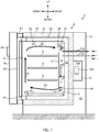
- FIG. 1 illustrates a schematic longitudinal section of the culture apparatus of an embodiment of the present invention as seen from the right side.
- Culture apparatus 1 illustrated in FIG. 1 is an apparatus for incubating a culture such as a cell or a microorganism.
- Culture apparatus 1 is configured to include substantially box-shaped heat insulation box 2 having culture space 20 formed inside and opening 21 formed in the front surface, outer door 3a and inner door 3b for opening and closing opening 21.
- Culture space 20 is vertically compartmentalized by a plurality of (here, three) shelves 4.
- Packing P1 is disposed on the outer edge of outer door 3a.
- the temperature, humidity, O 2 (oxygen) concentration, and CO 2 (carbon dioxide) concentration are controlled to be maintained within respective suitable ranges such that an environment of the culture space becomes a suitable environment for incubating the culture.
- Heat insulation box 2 includes substantially box-shaped inner box 2a having culture space 20 formed inside, and substantially box-shaped outer box 2b that covers the outside of inner box 2a.
- Outer box 2b is provided, on its inner surface side, with heat insulation material 2c.
- Space S1 is formed between the inner surface of heat insulation material 2c of outer box 2b and the outer surface of inner box 2a in such a manner as to cover the upper, lower, left, right, and rear sides of inner box 2a.
- This space S1 is filled with air; the air layer (so-called air jacket) 2d is formed in space S1.
- Space S1 has an opening in the front, and this opening is sealed with packing P2.
- ultraviolet lamp 7 and gas supply pipes 12a and 12b for supplying, to culture space 20, adjustment gases (O 2 gas, N 2 gas, and CO 2 gas) for adjusting O 2 gas concentration and CO 2 gas concentration in culture space 20 are installed within duct 5.
- Ultraviolet lamp 7 sterilizes water W in humidification tray 6 described later.
- humidification tray 6 for storing water W for humidification (hereinafter referred to as “humidification water W”) is installed between the lower portion of duct 5 and bottom wall 2a1 of inner box 2a.
- Humidification tray 6 is heated by a linear heater (hereinafter referred to as “heater wire”) H1 (see FIGS. 2 and 3 ) disposed on the lower surface of bottom wall 2a1 of inner box 2a.
- heater wire H1 is a humidity adjustment heater.
- heater wires H2 for temperature adjustment, that is, for controlling the temperature in culture space 20, are installed respectively on the rear surfaces (surfaces on the side of outer box 2b) of the right side wall, the left side wall, the rear wall, the top wall, and the bottom wall of inner box 2a. Note that heater wires H2 are being energized and generating heat, in principle, during the operation of culture apparatus 1.
- heater wire H1 and heater wires H2 are provided separately, and the energization rate of the heater wires are individually controlled by controller 100 to control the outputs (heating forces) individually.
- culture apparatus 1 receives instructions to start and stop culture apparatus 1 and/or inputs of various setting values of culture space 20 from operation device 50 disposed on outer door 3a.
- the various setting values of culture space 20 are a set temperature, set humidity, set concentration of O 2 gas, set concentration of CO 2 gas, and the like.
- Controller 100 controls the temperature, humidity, O 2 concentration, CO 2 concentration, and the like in culture space 20 such that the temperature, humidity, O 2 concentration, CO 2 concentration, and the like achieve the above-mentioned set values.
- dew condensation member 11a is inserted into culture space 20.
- Dew condensation member 11a is cooled by a Peltier element (not illustrated). Accordingly, condensation water is generated on the surface of dew condensation member 11a in culture space 20. Generation of the condensation water makes it possible to reduce the humidity in culture space 20 to control the humidity within an appropriate range. Note that, the condensation water generated on the surface of dew condensation member 11a drips from the tip of dew condensation member 11a into humidification tray 6.
- FIG. 2 schematically illustrates the pattern of heater wires H1 and H2 as seen from above.
- bottom wall 2a1 of inner box 2a and humidification tray 6 are indicated by broken lines.
- heater wire H1 is connected to power cables e10 and e11 via crimp terminals c10 and c11.
- heater wire H2 is connected to power cables e20 and e21 via crimp terminals c20 and c21.
- Humidity adjustment heater wire H1 repeatedly meanders in the front-rear direction (second direction) or the left-right direction (first direction) while forming U-shapes, and is disposed mostly below humidification tray 6.
- Temperature adjustment heater wire H2 repeatedly meanders similarly in the front-rear direction or the left-right direction while forming U-shapes, and is disposed substantially over entire bottom wall 2a1.
- a portion of temperature adjustment heater wire H2 disposed below humidification tray 6 includes, in the middle in the left-right direction, U-turn portion h20 (first portion) extending in the front-rear direction.
- U-turn portion h20 first portion
- U-turn portions h21 second portions
- U-turn portions h22 second portions
- U-turn portions h21 and h22 have the same arrangements in the front-rear direction.
- U-turn portions h21 and h22 form pairs and a plurality of pairs of U-turn portions h21 and h22 are disposed to be spaced from one another in the front-rear direction.
- a large portion of humidity adjustment heater wire H1 disposed below humidification tray 6 includes U-turn portions h10 and h11 (third portions) extending in the front-rear direction respectively at the left and right side edges of humidification tray 6.
- a plurality of U-turn portions h12 and h13 (fourth portions) extending to the vicinity of center line CL of humidification tray 6 in the left-right direction are connected to U-turn portions h10 and h11, respectively.
- a plurality of U-turn portions h12 extending in the right direction are connected to left U-turn portion h10
- a plurality of U-turn portions h13 extending in the left direction are connected to right U-turn portion h11.
- U-turn portions h12 and h13 have the same arrangements in the front-rear direction.
- U-turn portions h12 are disposed between and ahead of or behind U-turn portions h21 of temperature adjustment heater wire H2
- U-turn portions h13 are disposed between and ahead of or behind U-turn portions h22 of temperature adjustment heater wire H2.
- U-turn portions h12 and h21 are alternately arranged in the front-rear direction
- U-turn portions h13 and h22 are alternately arranged in the front-rear direction.
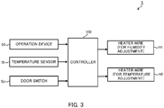
- FIG. 3 is a schematic functional block diagram illustrating the principal part of the control configuration of culture apparatus 1 of an embodiment of the present invention.
- operation device 50, temperature sensor St, and door switch Sd input control signals to controller 100. Further, controller 100 outputs a control command to heater wires H1 and H2.
- Operation device 50 receives various inputs. Specifically, operation device 50 receives an operation of starting (turning on the power of) culture apparatus 1, an operation of stopping (turning off the power of) culture apparatus 1, and an operation of inputting various settings such as set temperature T, set humidity, set CO 2 concentration x [%], and set O 2 concentration y [%] in culture space 20. Operation device 50 inputs these as control signals to controller 100. Note that, the function of setting the humidity may be omitted.
- Temperature sensor St detects the temperature in culture space 20, and outputs the detected temperature to controller 100 as a control signal.
- Door switch Sd detects the opening and closing of outer door 3a.
- Door switch Sd may output a closing signal in the closed state of outer door 3a, and output a closing signal in the open state of outer door 3a, or may output a signal only in either of the closed state and the open state of outer door 3a.
- controller 100 controls the output of temperature adjustment heater wire H2 based on the temperature in culture space 20 detected by temperature sensor St (hereinafter referred to as "temperature detection value"). Specifically, the energization rate of heater wire H2 is controlled such that the heating force of heater wire H2 increases when the temperature detection value is lower than set temperature T by a predetermined value or by a value greater than the predetermined value, and such that the heating force of heater wire H2 decreases when the temperature detection value is higher than set temperature T by a predetermined value or by a value greater than the predetermined value.
- controller 100 increases the heating power (output) of heater wire H1 by increasing the energization rate of humidity adjustment heater wire H1.
- controller 100 determines that the humidity in the culture space needs to be quickly increased in each of the cases where following condition 1 is satisfied and following condition 2 is satisfied, and increases the output of heater wire H1 from the output in a normal time.
- the normal time means a case where neither condition 1 nor condition 2 is satisfied.
- the output of heater wire H1 in the normal time includes 0 (zero). That is, an aspect of the present invention includes the case where heater wire H1 is energized only when following condition 1 is satisfied or when following condition 2 is satisfied, while otherwise is not energized in the normal time.
- controller 100 Based on the detection signal of door switch Sd, controller 100 has determined that outer door 3a is in the open state. Specifically, controller 100 has determined that culture space 20 is in a released state, because the detection signal of temperature sensor St indicated that the temperature in culture space 20 has decreased by a predetermined value or a value greater than the predetermined value while the controller has been determining, based on the detection signal of door switch Sd, that outer door 3a is in the open state. That is, it was presumed that air having a high humidity in culture space 20 has been discharged since culture space 20 has been in the released state and, instead, air around culture apparatus 1 having a relatively low humidity has flowed into culture space 20.
- controller 100 lowers the output of heater wire H1 back to the output in the normal time when a predetermined time elapses since it is determined, based on the detection signal of door switch Sd, that outer door 3a is switched to the closed state.
- controller 100 has a timer function, and counts the predetermined time using the timer function.
- the predetermined time has not elapsed since controller 100 received the operation of turning on the power from operation device 50. That is, humidification of culture space 20 by the use of heater H1 has just been started and the humidity in culture space 20 is much lower than the appropriate range (range suitable for incubating a culture).
- controller 100 lowers the output of heater wire H1 back to the output in the normal time when a predetermined time elapses since controller 100 received the operation of turning on the power from operation device 50.
- controller 100 may be configured to control the output of heater wire H1 such that the output of heater wire H1 is higher than that in the normal time when above-described condition 1 is satisfied, and set the output of heater wire H1 to the output in the normal time even when above-described condition 2 is satisfied. Conversely, controller 100 may be configured to set the output of heater wire H1 to the output in the normal time even when above-described condition 1 is satisfied, and control the output of heater wire H1 such that the output of heater wire H1 is higher than that in the normal time when above-described condition 2 is satisfied.
- the present invention is suitably utilized as a culture apparatus.
Landscapes
- Chemical & Material Sciences (AREA)
- Engineering & Computer Science (AREA)
- Health & Medical Sciences (AREA)
- Wood Science & Technology (AREA)
- Organic Chemistry (AREA)
- Life Sciences & Earth Sciences (AREA)
- Bioinformatics & Cheminformatics (AREA)
- Zoology (AREA)
- Biomedical Technology (AREA)
- Genetics & Genomics (AREA)
- Microbiology (AREA)
- Biotechnology (AREA)
- Biochemistry (AREA)
- General Engineering & Computer Science (AREA)
- General Health & Medical Sciences (AREA)
- Sustainable Development (AREA)
- Analytical Chemistry (AREA)
- Physics & Mathematics (AREA)
- Thermal Sciences (AREA)
- Clinical Laboratory Science (AREA)
- Computer Hardware Design (AREA)
- Apparatus Associated With Microorganisms And Enzymes (AREA)
Abstract
Description
- The present invention relates to a culture apparatus.
- In a culture apparatus (incubator) for incubating a culture such as a cell or a microorganism, it is necessary to control the humidity in a culture space at a humidity suitable for incubating the culture (see, for example, Patent Literature (hereinafter, referred to as "PTL") 1)
- Humidification of the culture space is performed using a humidification tray placed on the bottom wall of the culture space. Specifically, the culture space is humidified by heating the humidification tray with a heater wire disposed on the bottom wall to evaporate water in the humidification tray.
- The humidification tray is heated by a portion of the heater wire used to adjust the temperature in the culture space, specifically, by the portion located at the periphery of the humidification tray. That is, a single heater wire is used for both temperature adjustment and humidity adjustment.
-
PTL 1
Japanese Patent Application Laid-Open No. 2017-201886 - As described above, since the single heater wire is used for both temperature adjustment and humidity adjustment in the conventional culture apparatus, the capacity of the heater wire is increased, and the following problems have occurred.
- (1) Fine control on the output of the heater wire is difficult, and it is thus difficult to finely control the humidity.
- (2) The responsiveness of the heater wire is low, and is it thus impossible to quickly increase the humidity in the culture space to a range suitable for incubation of the culture.
- The present invention has been devised to solve such problems, and aims to provide a culture apparatus capable of finely and quickly adjusting the humidity in a culture space.
- In order to solve the above-mentioned conventional problems, a culture apparatus of the present invention includes: a humidification tray that is disposed in a culture space and stores a humidification liquid; a first heater that heats the humidification tray; and a second heater for controlling a temperature in the culture space, in which the first heater and the second heater are separately provided.
- According to the present invention, it is possible to finely and quickly adjust the humidity in the culture space.
-
-
FIG. 1 illustrates a schematic longitudinal section of a culture apparatus of an embodiment of the present invention as seen from the right side; -
FIG. 2 is a schematic plan view illustrating a pattern of heater wires; and -
FIG. 3 is a schematic functional block diagram illustrating a principal part of a control configuration of the culture apparatus of an embodiment of the present invention. - Hereinafter, a culture apparatus according to an embodiment of the present invention will be described with reference to the accompanying drawings. The following embodiments are merely illustrative, and various modifications and/or applications of techniques which are not specified in the following embodiments are not excluded. In addition, the configurations of the embodiments can be variously modified and implemented without departing from the spirit thereof. Further, the configurations of the embodiments can be selected as necessary, or can be appropriately combined.
- In the following description, the side of the culture apparatus which the user faces during usage of the culture apparatus (the side with below-described
outer door 3a andinner door 3b) is referred to as "front" and the side opposite to the front is referred to as "rear." In addition, the left and right are defined with reference to the case of viewing from the front to the rear. - Note that, in all the figures for explaining the embodiments, the same elements are denoted by the same reference numerals in principle, and the description thereof may be omitted.
- A description will be given of an entire culture apparatus of an embodiment of the present invention with reference to
FIG. 1. FIG. 1 illustrates a schematic longitudinal section of the culture apparatus of an embodiment of the present invention as seen from the right side. -
Culture apparatus 1 illustrated inFIG. 1 is an apparatus for incubating a culture such as a cell or a microorganism.Culture apparatus 1 is configured to include substantially box-shapedheat insulation box 2 havingculture space 20 formed inside and opening 21 formed in the front surface,outer door 3a andinner door 3b for opening and closingopening 21.Culture space 20 is vertically compartmentalized by a plurality of (here, three)shelves 4. Packing P1 is disposed on the outer edge ofouter door 3a. - The temperature, humidity, O2 (oxygen) concentration, and CO2 (carbon dioxide) concentration are controlled to be maintained within respective suitable ranges such that an environment of the culture space becomes a suitable environment for incubating the culture.
-
Heat insulation box 2 includes substantially box-shapedinner box 2a havingculture space 20 formed inside, and substantially box-shapedouter box 2b that covers the outside ofinner box 2a. -
Outer box 2b is provided, on its inner surface side, withheat insulation material 2c. Space S1 is formed between the inner surface ofheat insulation material 2c ofouter box 2b and the outer surface ofinner box 2a in such a manner as to cover the upper, lower, left, right, and rear sides ofinner box 2a. This space S1 is filled with air; the air layer (so-called air jacket) 2d is formed in space S1. Space S1 has an opening in the front, and this opening is sealed with packing P2. - In
culture space 20, vertically extendingduct 5 is disposed on the rear surface ofinner box 2a. Gas passage K is formed insideduct 5.Circulation blower 5c is disposed in gas passage K. Byoperating circulation blower 5c, air inculture space 20 is sucked throughsuction port 5a formed in an upper portion ofduct 5, and this air is blown out toculture space 20 through blow-outport 5b formed in a lower portion ofduct 5. Thus, forced circulation of the air as indicated by arrows A1, A2, A3, and A4 takes place. - In addition,
ultraviolet lamp 7 andgas supply pipes culture space 20, adjustment gases (O2 gas, N2 gas, and CO2 gas) for adjusting O2 gas concentration and CO2 gas concentration inculture space 20 are installed withinduct 5.Ultraviolet lamp 7 sterilizes water W inhumidification tray 6 described later. - In addition, humidification tray 6 for storing water W for humidification (hereinafter referred to as "humidification water W") is installed between the lower portion of
duct 5 and bottom wall 2a1 ofinner box 2a.Humidification tray 6 is heated by a linear heater (hereinafter referred to as "heater wire") H1 (seeFIGS. 2 and3 ) disposed on the lower surface of bottom wall 2a1 ofinner box 2a. Heated by heater wire HI, humidification water W is evaporated to humidifyculture space 20. That is, heater wire H1 is a humidity adjustment heater. - In addition, heater wires H2 (see
FIGS. 2 and3 ) for temperature adjustment, that is, for controlling the temperature inculture space 20, are installed respectively on the rear surfaces (surfaces on the side ofouter box 2b) of the right side wall, the left side wall, the rear wall, the top wall, and the bottom wall ofinner box 2a. Note that heater wires H2 are being energized and generating heat, in principle, during the operation ofculture apparatus 1. - These heater wire H1 and heater wires H2 are provided separately, and the energization rate of the heater wires are individually controlled by
controller 100 to control the outputs (heating forces) individually. - In addition,
culture apparatus 1 receives instructions to start and stopculture apparatus 1 and/or inputs of various setting values ofculture space 20 fromoperation device 50 disposed onouter door 3a. The various setting values ofculture space 20 are a set temperature, set humidity, set concentration of O2 gas, set concentration of CO2 gas, and the like.Controller 100 controls the temperature, humidity, O2 concentration, CO2 concentration, and the like inculture space 20 such that the temperature, humidity, O2 concentration, CO2 concentration, and the like achieve the above-mentioned set values. - The rear and bottom surfaces of
outer box 2b ofheat insulation box 2 are covered withcover 10. The space between the rear surface ofouter box 2b and cover 10 forms mechanical room S2 for disposing various equipment therein.Electrical box 13 is disposed in mechanical room S2.Controller 100 and other electrical components (not illustrated) are housed in inside 13a ofelectrical box 13. - Further, the tip of
dew condensation member 11a is inserted intoculture space 20.Dew condensation member 11a is cooled by a Peltier element (not illustrated). Accordingly, condensation water is generated on the surface ofdew condensation member 11a inculture space 20. Generation of the condensation water makes it possible to reduce the humidity inculture space 20 to control the humidity within an appropriate range. Note that, the condensation water generated on the surface ofdew condensation member 11a drips from the tip ofdew condensation member 11a intohumidification tray 6. - A description will be given of a pattern of heater wires H1 and H2 (heater pattern) with reference to
FIG. 2. FIG. 2 schematically illustrates the pattern of heater wires H1 and H2 as seen from above. InFIG. 2 , for convenience, bottom wall 2a1 ofinner box 2a andhumidification tray 6 are indicated by broken lines. - As illustrated in
FIG. 2 , heater wire H1 is connected to power cables e10 and e11 via crimp terminals c10 and c11. Likewise, heater wire H2 is connected to power cables e20 and e21 via crimp terminals c20 and c21. - Humidity adjustment heater wire H1 repeatedly meanders in the front-rear direction (second direction) or the left-right direction (first direction) while forming U-shapes, and is disposed mostly below
humidification tray 6. Temperature adjustment heater wire H2 repeatedly meanders similarly in the front-rear direction or the left-right direction while forming U-shapes, and is disposed substantially over entire bottom wall 2a1. - Focusing on the lower side of
humidification tray 6, a portion of temperature adjustment heater wire H2 disposed belowhumidification tray 6 includes, in the middle in the left-right direction, U-turn portion h20 (first portion) extending in the front-rear direction. A plurality of U-turn portions h21 (second portions) extending in the left direction and a plurality of U-turn portions h22 (second portions) extending in the right direction are connected to U-turn portion h20. U-turn portions h21 and h22 have the same arrangements in the front-rear direction. U-turn portions h21 and h22 form pairs and a plurality of pairs of U-turn portions h21 and h22 are disposed to be spaced from one another in the front-rear direction. - Likewise, focusing on the lower side of
humidification tray 6, a large portion of humidity adjustment heater wire H1 disposed belowhumidification tray 6 includes U-turn portions h10 and h11 (third portions) extending in the front-rear direction respectively at the left and right side edges ofhumidification tray 6. A plurality of U-turn portions h12 and h13 (fourth portions) extending to the vicinity of center line CL ofhumidification tray 6 in the left-right direction are connected to U-turn portions h10 and h11, respectively. Specifically, a plurality of U-turn portions h12 extending in the right direction are connected to left U-turn portion h10, and a plurality of U-turn portions h13 extending in the left direction are connected to right U-turn portion h11. U-turn portions h12 and h13 have the same arrangements in the front-rear direction. U-turn portions h12 are disposed between and ahead of or behind U-turn portions h21 of temperature adjustment heater wire H2, and U-turn portions h13 are disposed between and ahead of or behind U-turn portions h22 of temperature adjustment heater wire H2. In other words, U-turn portions h12 and h21 are alternately arranged in the front-rear direction, and likewise, U-turn portions h13 and h22 are alternately arranged in the front-rear direction. - Hereinafter, a principal part of a control configuration of
culture apparatus 1 of an embodiment of the present invention will be described with reference toFIG. 3 . -
FIG. 3 is a schematic functional block diagram illustrating the principal part of the control configuration ofculture apparatus 1 of an embodiment of the present invention. - As illustrated in
FIG. 3 ,operation device 50, temperature sensor St, and door switch Sd input control signals tocontroller 100. Further,controller 100 outputs a control command to heater wires H1 and H2. -
Operation device 50 receives various inputs. Specifically,operation device 50 receives an operation of starting (turning on the power of)culture apparatus 1, an operation of stopping (turning off the power of)culture apparatus 1, and an operation of inputting various settings such as set temperature T, set humidity, set CO2 concentration x [%], and set O2 concentration y [%] inculture space 20.Operation device 50 inputs these as control signals tocontroller 100. Note that, the function of setting the humidity may be omitted. - Temperature sensor St detects the temperature in
culture space 20, and outputs the detected temperature tocontroller 100 as a control signal. - Door switch Sd detects the opening and closing of
outer door 3a. Door switch Sd may output a closing signal in the closed state ofouter door 3a, and output a closing signal in the open state ofouter door 3a, or may output a signal only in either of the closed state and the open state ofouter door 3a. - Further,
controller 100 controls the output of temperature adjustment heater wire H2 based on the temperature inculture space 20 detected by temperature sensor St (hereinafter referred to as "temperature detection value"). Specifically, the energization rate of heater wire H2 is controlled such that the heating force of heater wire H2 increases when the temperature detection value is lower than set temperature T by a predetermined value or by a value greater than the predetermined value, and such that the heating force of heater wire H2 decreases when the temperature detection value is higher than set temperature T by a predetermined value or by a value greater than the predetermined value. - In addition, when it is necessary to increase the humidity in
culture space 20 quickly,controller 100 increases the heating power (output) of heater wire H1 by increasing the energization rate of humidity adjustment heater wire H1. - Further,
controller 100 determines that the humidity in the culture space needs to be quickly increased in each of the cases where followingcondition 1 is satisfied and followingcondition 2 is satisfied, and increases the output of heater wire H1 from the output in a normal time. Here, the normal time means a case where neithercondition 1 norcondition 2 is satisfied. The output of heater wire H1 in the normal time includes 0 (zero). That is, an aspect of the present invention includes the case where heater wire H1 is energized only when followingcondition 1 is satisfied or when followingcondition 2 is satisfied, while otherwise is not energized in the normal time. - Based on the detection signal of door switch Sd,
controller 100 has determined thatouter door 3a is in the open state. Specifically,controller 100 has determined thatculture space 20 is in a released state, because the detection signal of temperature sensor St indicated that the temperature inculture space 20 has decreased by a predetermined value or a value greater than the predetermined value while the controller has been determining, based on the detection signal of door switch Sd, thatouter door 3a is in the open state. That is, it was presumed that air having a high humidity inculture space 20 has been discharged sinceculture space 20 has been in the released state and, instead, air aroundculture apparatus 1 having a relatively low humidity has flowed intoculture space 20. - In the case where this
condition 1 is satisfied and the output of heater wire H1 is controlled such that the output of heater wire H1 is higher than that in the normal time,controller 100 lowers the output of heater wire H1 back to the output in the normal time when a predetermined time elapses since it is determined, based on the detection signal of door switch Sd, thatouter door 3a is switched to the closed state. Note that,controller 100 has a timer function, and counts the predetermined time using the timer function. - The predetermined time has not elapsed since
controller 100 received the operation of turning on the power fromoperation device 50. That is, humidification ofculture space 20 by the use of heater H1 has just been started and the humidity inculture space 20 is much lower than the appropriate range (range suitable for incubating a culture). - In the case where this
condition 2 is satisfied and the output of heater wire H1 is controlled such that the output of heater wire H1 is higher than that in the normal time,controller 100 lowers the output of heater wire H1 back to the output in the normal time when a predetermined time elapses sincecontroller 100 received the operation of turning on the power fromoperation device 50. - Note that,
controller 100 may be configured to control the output of heater wire H1 such that the output of heater wire H1 is higher than that in the normal time when above-describedcondition 1 is satisfied, and set the output of heater wire H1 to the output in the normal time even when above-describedcondition 2 is satisfied. Conversely,controller 100 may be configured to set the output of heater wire H1 to the output in the normal time even when above-describedcondition 1 is satisfied, and control the output of heater wire H1 such that the output of heater wire H1 is higher than that in the normal time when above-describedcondition 2 is satisfied. - According to an embodiment of the present invention, the following effects are obtained.
- (1) Humidity adjustment heater wire H1 is provided as a part separate from temperature adjustment heater wire H2. It is thus possible to reduce the capacity of heater wire H1 as compared with the conventional technique in which a single heater wire serves as both a temperature adjustment heater wire and a humidity adjustment heater wire. Consequently, it is possible to control the temperature of humidity adjustment heater wire H1 more finely and with higher responsiveness than in the conventional technique. Thus, according to an embodiment of the present invention, the humidity in
culture space 20 can be finely and quickly adjusted. - (2) Although dew condensation is likely to occur at a portion between bottom wall 2a1 of
inner box 2a andhumidification tray 6, humidity adjustment heater wire H1 is disposed belowhumidification tray 6, and it is thus possible to reduce the dew condensation at the portion effectively by heater wire H1. - (3)
Humidification tray 6 is heated by a portion of temperature adjustment heater wire H2. Thus, the heating amount for adjusting the humidity inculture space 20 can be covered only by heater wire H2 in the normal time in which it is particularly unnecessary to increase the evaporation amount of humidification water W. Alternatively, it is possible to reduce the output of humidity adjustment heater wire H1 in the normal time. - (4) Since temperature adjustment heater wire H2 is also disposed below
humidification tray 6, it is possible to effectively reduce the dew condensation at the portion between bottom wall 2a1 ofinner box 2a andhumidification tray 6 by heating the portion where the dew condensation is likely to occur. - (5) Temperature adjustment heater H2 to be steadily energized includes U-turn portion h20 disposed on center line CL of humidification tray 6 (or near center line CL) in plan view, U-turn portions h21 and h22 extending from the U-turn portion h20 to the left and right. Thus, the temperature adjustment heater is disposed with respect to
humidification tray 6 without deviation, and it is possible to reduce the occurrence of a cold spot at which the temperature is locally low inhumidification tray 6, so as to humidifyculture space 20 stably and steadily.
Further, U-turn portions h10, h11, h12, and h13 of humidity adjustment heater H1 are disposed to fill gaps between U-turn portions h20, h21, and h22 of temperature adjustment heater H2. It is thus possible to more effectively prevent the occurrence of the cold spot inhumidification tray 6 so as to quickly increase the humidity inculture space 20 to the appropriate range. - (6)
Controller 100 can control heater wires H1 and H2 individually. Thus, in order to increase the evaporation amount of humidification water W, only the output of heater wire H1 can be increased without changing the output of temperature adjustment heater wire H2. Accordingly, it is possible to adjust the humidity inculture space 20 while preventing disturbance to the temperature inculture space 20. Note that, when the output of heater wire H1 is increased, the output of heater wire H2 may be slightly decreased in order to further reduce the fluctuation (rise) in the temperature inculture space 20. - (7) On the condition that door switch Sd has detected the open state of
outer door 3a,controller 100 increases the output of heater wire H1 to an output higher than that in the normal time (higher than an output during when door switch Sd detects the closed state ofouter door 3a). Consequently, even when the humidity inculture space 20 rapidly decreases becauseouter door 3a andinner door 3b are opened, this decrease is cancelled out by an increase in the evaporation of humidification water W caused by an increase in the output of heater wire H1. It is thus possible to maintain the humidity inculture space 20 within the appropriate range. - (8) On the condition that a predetermined time has not elapsed since the operation of turning on the power was received from
operation device 50,controller 100 increases the output of heater wire H1 to an output higher than the output in the normal time (the output after the predetermined time has elapsed since the operation of turning on the power was received). Consequently, when the humidity inculture space 20 has not yet been increased to the appropriate range becauseculture apparatus 1 has been just started, the humidity inculture space 20 can be increased to the appropriate range quickly. -
- (1) Temperature adjustment heater wire H2 may be removed from the lower surface of
humidification tray 6, andhumidification tray 6 may not be heated by heater wire H2. That is,humidification tray 6 may be heated only by humidity adjustment heater wire H1. - (2) The outputs of heaters H1 and H2 may be manually operated by an operator, either in conjunction with the control of
controller 100 or in place of the control ofcontroller 100. - (3) The pattern of heaters H1 and H2 is not limited to that illustrated in
FIG. 2 , and is appropriately changed depending on the size and shape ofhumidification tray 6. - The disclosure of
Japanese Patent Application No. 2018-201702, filed on October 26, 2018 - The present invention is suitably utilized as a culture apparatus.
-
- 1 Culture apparatus
- 2 Heat insulation box
- 2a Inner box
- 2a1 Bottom wall
- 2b Outer box
- 2c Heat insulation material
- 2d Air layer
- 3 a Outer door
- 3b Inner door
- 4 Shelf
- 5 Duct
- 5a Suction port
- 5b Blow-out port
- 5c Circulation blower
- 6 Humidification tray
- 7 Ultraviolet lamp
- 10 Cover
- 11a Dew condensation member
- 12a, 12b Gas supply pipe
- 13 Electrical box
- 13a Inside of electrical box
- 20 Culture space
- 21 Opening
- 50 Operation device
- 100 Controller
- c21, c10, c11, c20 Crimp terminal
- CL Center line of
humidification tray 6 in left-right direction - e10, e11, e20, e21 Power cable
- H1 Humidity adjustment heater wire (first heater)
- H2 Temperature adjustment heater wire (second heater)
- h10, h11 U-turn portion (third portion)
- h12, h13 U-turn portion (fourth portion)
- h20 U-turn portion (first portion)
- h21, h22 U-turn portion (second portion)
- K Gas passage
- P I, P2 Packing
- S1 Space
- S2 Mechanical room
- St Temperature sensor
- Sd Door switch
- W Water
Claims (9)
- A culture apparatus, comprising:a humidification tray that is disposed in a culture space and stores a humidification liquid;a first heater that heats the humidification tray; anda second heater for controlling a temperature in the culture space, whereinthe first heater and the second heater are separately provided.
- The culture apparatus according to claim 1, wherein
the first heater is disposed below the humidification tray. - The culture apparatus according to claims 1 or 2, wherein
a portion of the second heater heats the humidification tray. - The culture apparatus according to claim 3, wherein
the portion of the second heater is disposed below the humidification tray. - The culture apparatus according to claim 1, wherein
the first heater and a portion of the second heater are disposed below the humidification tray,
the portion of the second heater comprises:a first portion disposed in a middle of the humidification tray in a first direction and extending in a second direction crossing the first direction, anda plurality of second portions extending from the first portion in the first direction and disposed to be spaced apart from one another in the second direction,and
the first heater comprises:third portions being two in number, the third portions being disposed on opposite outer sides of the portion of the second heater in the first direction and extending in the second direction, anda fourth portions extending from the third portions in the first direction and disposed between the plurality of second portions. - The culture apparatus according to any one according to claims 1 to 5, further comprising:
a controller that controls an output of the first heater and an output of the second heater individually. - The culture apparatus according to claim 6, further comprising:a door that opens and closes the culture space; anda detection device that detects opening and closing of the door, whereinthe controller controls the output of the first heater based on a detection result of the detection device.
- The culture apparatus according to claim 7, wherein,
on condition that the controller determines that the door is in an open state based on the detection result of the detection device, the controller controls the output of the first heater such that the output of the first heater is higher than that in a case where the door is determined to be in a closed state based on the detection result. - The culture apparatus according to any one according to claims 6 to 8, wherein
the controller controls the output of the first heater, until a predetermined time elapses after power of the culture apparatus is turned on, such that the output of the first heater is higher than that after the predetermined time elapses.
Applications Claiming Priority (2)
| Application Number | Priority Date | Filing Date | Title |
|---|---|---|---|
| JP2018201702 | 2018-10-26 | ||
| PCT/JP2019/038346 WO2020085006A1 (en) | 2018-10-26 | 2019-09-27 | Culturing apparatus |
Publications (2)
| Publication Number | Publication Date |
|---|---|
| EP3851512A1 true EP3851512A1 (en) | 2021-07-21 |
| EP3851512A4 EP3851512A4 (en) | 2021-11-17 |
Family
ID=70330689
Family Applications (1)
| Application Number | Title | Priority Date | Filing Date |
|---|---|---|---|
| EP19877491.1A Withdrawn EP3851512A4 (en) | 2018-10-26 | 2019-09-27 | CULTURAL DEVICE |
Country Status (5)
| Country | Link |
|---|---|
| US (1) | US20210238531A1 (en) |
| EP (1) | EP3851512A4 (en) |
| JP (1) | JPWO2020085006A1 (en) |
| CN (1) | CN112912483A (en) |
| WO (1) | WO2020085006A1 (en) |
Family Cites Families (9)
| Publication number | Priority date | Publication date | Assignee | Title |
|---|---|---|---|---|
| JPH05227942A (en) * | 1992-02-25 | 1993-09-07 | Unie Data:Kk | Apparatus for culturing |
| JP3197696B2 (en) * | 1993-07-22 | 2001-08-13 | 三洋電機株式会社 | Culture device |
| CN203474780U (en) * | 2013-08-19 | 2014-03-12 | 上海力申科学仪器有限公司 | Humidifying condensing equipment for incubator |
| JP6753680B2 (en) * | 2016-03-28 | 2020-09-09 | Phcホールディングス株式会社 | Incubator |
| JP6713344B2 (en) | 2016-05-09 | 2020-06-24 | 株式会社エアレックス | incubator |
| JP2018201702A (en) | 2017-05-31 | 2018-12-27 | 株式会社三洋物産 | Game machine |
| WO2020049970A1 (en) * | 2018-09-06 | 2020-03-12 | Phc株式会社 | Culture device |
| EP3825395B1 (en) * | 2018-09-06 | 2022-07-06 | PHC Corporation | Culture device |
| JP7262966B2 (en) * | 2018-10-18 | 2023-04-24 | リュ ルン-クァン | cell incubator |
-
2019
- 2019-09-27 JP JP2020553020A patent/JPWO2020085006A1/en active Pending
- 2019-09-27 EP EP19877491.1A patent/EP3851512A4/en not_active Withdrawn
- 2019-09-27 CN CN201980069924.8A patent/CN112912483A/en active Pending
- 2019-09-27 WO PCT/JP2019/038346 patent/WO2020085006A1/en not_active Ceased
-
2021
- 2021-04-20 US US17/235,532 patent/US20210238531A1/en not_active Abandoned
Also Published As
| Publication number | Publication date |
|---|---|
| EP3851512A4 (en) | 2021-11-17 |
| JPWO2020085006A1 (en) | 2021-09-02 |
| WO2020085006A1 (en) | 2020-04-30 |
| US20210238531A1 (en) | 2021-08-05 |
| CN112912483A (en) | 2021-06-04 |
Similar Documents
| Publication | Publication Date | Title |
|---|---|---|
| US10704020B2 (en) | Incubator | |
| JPH0731463A (en) | Incubator | |
| JP5897855B2 (en) | Incubator with heater | |
| US11098277B2 (en) | Culture apparatus and method of controlling culture apparatus | |
| US20200199518A1 (en) | Incubator | |
| US20210284949A1 (en) | Culture device | |
| KR101652431B1 (en) | Heat treatment apparatus | |
| JP6713344B2 (en) | incubator | |
| JP2016109682A (en) | Environmental test device | |
| US20100035106A1 (en) | Fuel cell system | |
| US10918755B2 (en) | Housing apparatus | |
| US12297419B2 (en) | Culture device | |
| US20210238531A1 (en) | Culturing apparatus | |
| JP2017175944A (en) | Incubator | |
| JP6753680B2 (en) | Incubator | |
| CN216614706U (en) | Three-gas oscillation incubator | |
| JP2020092715A (en) | incubator | |
| JP2003068340A (en) | Gas supply apparatus and inspection system | |
| JPH0452215A (en) | Vacuum furnace and temperature equalization method in vacuum furnace | |
| JP2001324176A (en) | Blast temperature control vessel | |
| JPH0429311Y2 (en) | ||
| JP2008137875A (en) | Oxygen partial pressure controller | |
| KR20250056412A (en) | Condensation prevention device for carbon dioxide cell incubator | |
| JP2024024564A (en) | Constant temperature and humidity device and guide members | |
| JPH05289755A (en) | Thermostatic chamber |
Legal Events
| Date | Code | Title | Description |
|---|---|---|---|
| STAA | Information on the status of an ep patent application or granted ep patent |
Free format text: STATUS: THE INTERNATIONAL PUBLICATION HAS BEEN MADE |
|
| PUAI | Public reference made under article 153(3) epc to a published international application that has entered the european phase |
Free format text: ORIGINAL CODE: 0009012 |
|
| STAA | Information on the status of an ep patent application or granted ep patent |
Free format text: STATUS: REQUEST FOR EXAMINATION WAS MADE |
|
| 17P | Request for examination filed |
Effective date: 20210416 |
|
| AK | Designated contracting states |
Kind code of ref document: A1 Designated state(s): AL AT BE BG CH CY CZ DE DK EE ES FI FR GB GR HR HU IE IS IT LI LT LU LV MC MK MT NL NO PL PT RO RS SE SI SK SM TR |
|
| RIC1 | Information provided on ipc code assigned before grant |
Ipc: C12M 1/34 20060101ALI20211007BHEP Ipc: C12M 1/00 20060101AFI20211007BHEP |
|
| A4 | Supplementary search report drawn up and despatched |
Effective date: 20211014 |
|
| RIC1 | Information provided on ipc code assigned before grant |
Ipc: C12M 1/34 20060101ALI20211008BHEP Ipc: C12M 1/00 20060101AFI20211008BHEP |
|
| DAV | Request for validation of the european patent (deleted) | ||
| DAX | Request for extension of the european patent (deleted) | ||
| STAA | Information on the status of an ep patent application or granted ep patent |
Free format text: STATUS: THE APPLICATION HAS BEEN WITHDRAWN |
|
| 18W | Application withdrawn |
Effective date: 20220325 |