BACKGROUND
Technical Field
-
The present invention relates to a box packing device that packs bags in boxes.
Background Art
-
Conventionally, as in patent document 1 (
JP-A No. 2004-352287 ), packaging devices that manufacture bags containing objects have been known. The bags that the packaging device has manufactured are conveyed to a box packing device by a conveyance unit such as a belt conveyor, packed in boxes in the box packing device, and shipped. There are also many cases where the box packing device is supplied with bags from two packaging devices to increase throughput.
SUMMARY
Technical Problem
-
When installing two packaging devices, it is often difficult to dispose the two packaging devices in close proximity to each other for reasons such as avoiding contact between the members of the two packaging devices and ensuring maintenance space. For that reason, when installing two packaging devices side by side, normally the two packaging devices are installed a predetermined distance away from each other.
-
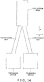
In such a situation, it is assumed a case that the two packaging devices conveys articles to a predetermined collection area of the box packing device. In this case, it is necessary, as in FIG. 14, to dispose the conveyance path of a conveyance unit leading from at least one packaging device to the box packing device so as to extend not only in the direction of arrow A approaching from the packaging device toward the box packing device but also in the direction of arrow B orthogonal to the direction of arrow A. As a result, there are the problems that the conveyance paths of the conveyance units tend to become long and the installation space of a system increases.
-
It is an object of the present invention to provide a box packing device, which receives supplies of bags from two places and packs the bags in boxes, which can inhibit an increase in the installation space of a system.
Solution to Problem
-
A box packing device pertaining to a first aspect of the invention includes a placement table, a first conveyance unit, a second conveyance unit, a first moving unit, a second moving unit, and a box packing mechanism. The placement table has on its upper portion a placement surface on which bags are placed. The placement table has a first edge portion disposed on one end side and a second edge portion disposed on the other end side of the placement table with respect to the first edge portion in plan view. The first conveyance unit is configured to convey the bag to a first position adjacent to the first edge portion of the placement table in plan view. The second conveyance unit is configured to convey the bag to a second position adjacent to the second edge portion of the placement table in plan view. The first moving unit is configured to move, to the placement surface, the bag that the first conveyance unit conveys to the first position. The second moving unit is configured to move, to the placement surface, the bag that the second conveyance unit conveys to the second position. The box packing mechanism is configured to pack in a box the bags that are placed on the placement surface.
-
In the box packing device of the first aspect, the bags which one packaging device supplies and which the first conveyance unit conveys and the bags which another packaging device supplies and which the second conveyance unit conveys are moved from both sides of the placement table to the placement surface. For that reason, the installation space of a system including the packaging devices and the box packing device can be reduced compared to a case where the two packaging devices directly convey the bags to the placement surface.
-
A box packing device pertaining to a second aspect of the invention is the box packing device of the first aspect, wherein the box in which the box packing mechanism packs the bags are disposed between the first edge portion and the second edge portion in plan view.
-
In the box packing device of the second aspect, since the box for box packing is disposed between the first edge portion and the second edge portion of the placement table in plan view, an increase in the size of the box packing device can be inhibited.
-
A box packing device pertaining to a third aspect of the invention is the box packing device of the first aspect or the second aspect, wherein the first moving unit includes a first guide member that is configured to move the bag parallel to the placement surface on the placement table. The second moving unit includes a second guide member that is configured to move the bag parallel to the placement surface on the placement table.
-
The box packing device of the third aspect moves the bags parallel to the placement surface, so compared to a structure that grips and lift the bags, the moving units can be simplified in structure and can move the bags in a short amount of time to the placement surface.
-
A box packing device pertaining to a fourth aspect of the invention is the box packing device of the third aspect, wherein the first guide member is configured to horizontally move from a first standby position along a first route to thereby horizontally move the bag on the placement surface. Thereafter the first guide member is configured to move a lower end portion thereof upward a predetermined distance and return to the first standby position via a second route disposed above the first route. The second guide member is configured to horizontally move from a second standby position along a third route to thereby horizontally move the bag on the placement surface. Thereafter, the second guide member is configured to move a lower end portion thereof upward a predetermined distance and return to the second standby position via a fourth route disposed above the third route.
-
In the box packing device of the fourth aspect, the guide members horizontally move from the standby positions to thereby move the bag to the placement surface and thereafter move over the horizontal moving routes to return to the standby positions. For that reason, in the box packing device of the fourth aspect, the guide members can be kept from contacting the bag even when the bag is moved to the placement table before the guide members return to the standby positions. For that reason, in the box packing device of the fourth aspect, the bag can be moved to the placement table in advance before the guide members returns to the standby positions, and the throughput of the box packing device can be improved.
-
A box packing device pertaining to a fifth aspect of the invention is the box packing device of the third aspect or the fourth aspect, wherein the first guide member and the second guide member are configured to sandwich between themselves a plurality of the bags on the placement surface.
-
The box packing device of the fifth aspect sandwiches the bags with the first guide member and the second guide member, so the plural bags on the placement surface can be aligned, and occurrence of problems in the box packing by the box packing mechanism that arise due to misalignment of the bags can be reduced. Furthermore, in the box packing device of the fifth aspect, the bags can be brought into close contact with each other as a result of the plural bags being sandwiched by the first guide member and the second guide member, so it is easy to improve the fill rate of the bags in the box during box packing.
-
A box packing device pertaining to a sixth aspect of the invention is the box packing device of the fifth aspect, wherein each of the bags includes a plurality of small bags connected in a row. The box packing mechanism is configured to change, in a first direction, the posture of each of the bags which are placed on the placement surface from a first posture to a second posture. In the bags in the first posture, the plural small bags are disposed extending linearly in a row along the first direction. In the bags in the second posture, at least a part of outer surface of each of the small bags contacts outer surface of other of the small bags. The first guide member and the second guide member are configured to sandwich the plural bags on the placement surface in a direction orthogonal to the first direction when the box packing mechanism changes the posture of the bags from the first posture to the second posture.
-
In the box packing device of the sixth aspect, when changing the posture of the continuous packaging bags so as to fold the continuous packaging bags in the first direction (the longitudinal direction in which the small bags aligns) to raise the fill rate in the boxes, the guide members sandwich the continuous packaging bags in a direction orthogonal to the first direction. For that reason, in the box packing device of the sixth aspect, the continuous packaging bags can be neatly folded, and it is easy to improve the fill rate of the bags in the boxes during box packing.
-
A box packing device pertaining to a seventh aspect of the invention is the box packing device of any of the first aspect to the sixth aspect, wherein the placement table has a first retention section and a second retention section. The first retention section is disposed between the first edge portion and the placement surface in plan view. The second retention section is disposed between the second edge portion and the placement surface in plan view. The first moving unit includes a first transfer member that is configured to move, to the first retention section, the bag that the first conveyance unit conveys to the first position. The second moving unit includes a second transfer member that is configured to move, to the second retention section, the bag that the second conveyance unit conveys to the second position.
-
The box packing device of the seventh aspect can, while moving the bag to the placement surface, prepare in the retention sections the bags to be moved next to the placement surface. For that reason, in the box packing device of the seventh aspect, the throughput of the box packing device can be improved.
-
A box packing device pertaining to an eighth aspect of the invention is the box packing device of the fourth aspect, wherein the placement table has a first retention section and a second retention section. The first retention section is disposed between the first edge portion and the placement surface in plan view. The second retention section is disposed between the second edge portion and the placement surface in plan view. The first guide member is configured to move along the first route while horizontally pushing the bag to thereby move the bag to the placement surface. Thereafter, the first guide member is configured to move over the bag placed in the first retention section to return to the first standby position. The second guide member is configured to move along the third route while horizontally pushing the bag to thereby move the bag to the placement surface. Thereafter, the second guide member is configured to move over the bag placed in the second retention section to return to the second standby position.
-
In the box packing device of the eighth aspect, the guide members move the bag to the placement surface and thereafter move over the bag placed in the retention sections to return to the standby positions. For that reason, in the box packing device of the eighth aspect, the bag can be moved in advance to the retention sections before the guide members return to the standby positions, and the throughput of the box packing device can be therefore improved.
-
A box packing device pertaining to a ninth aspect of the invention is the box packing device of any of the first aspect to the eighth aspect, wherein the box packing mechanism is capable of packing the bag that only the first moving unit moves to the placement surface or the bag that only the second moving unit has moves to the placement surface.
-
In the box packing device of the ninth aspect, box packing can be continued without stopping the box packing device even in a case where one of the packaging device that supplies the bag to the first conveyance unit and the packaging device that supplies the bag to the second conveyance unit stops for some reason.
-
A box packing device pertaining to a tenth aspect of the invention is the box packing device of any of the first aspect to the ninth aspect, wherein the first moving unit is configured to move, to the placement surface, a first type of the bag that the first conveyance unit conveys to the first position. The second moving unit is configured to move, to the placement surface, a second type of the bag that the second conveyance unit conveys to the second position. The second type is different from the first type.
-
In the box packing device of the tenth aspect, plural types of the bags can be packed in one box.
-
A box packing device pertaining to an eleventh aspect of the invention is the box packing device of the first aspect, wherein each of the bags includes a plurality of small bags connected in a row.
-
A box packing device pertaining to a twelfth aspect of the invention is the box packing device of any of the first aspect to the eleventh aspect, wherein the placement table extends in a second direction from the first edge portion to the second edge portion. The second direction is orthogonal to the direction in which the bag is conveyed by the first conveyance unit and the second conveyance unit in plan view.
Advantageous Effects of Invention
-
In the box packing device of the present invention, the bags which one packaging device supplies and which the first conveyance unit conveys and the bags which another packaging device supplies and which the second conveyance unit conveys are moved from both sides of the placement table to the placement surface. For that reason, the installation space of a system including the packaging devices and the box packing device can be reduced compared to a case where the two packaging devices directly convey the bags to the placement surface.
BRIEF DESCRIPTION OF DRAWINGS
-
- FIG. 1 is a general plan view of a box packing device pertaining to an embodiment of the present invention;
- FIG. 2 is a general plan view of a lower level portion of the box packing device of FIG. 1;
- FIG. 3 is a general left side view of the box packing device of FIG. 1;
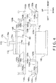
- FIG. 4 is a back elevation view of the box packing device of FIG. 1;
- FIG. 5A is a drawing for describing operations of a left-side lower level transfer unit of the box packing device of FIG. 1;
- FIG. 5B is a drawing for describing operations of a right-side lower level transfer unit of the box packing device of FIG. 1;
- FIG. 6 is a drawing for describing operations of a left-side guide unit and a right-side guide unit of the box packing device of FIG. 1;
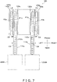
- FIG. 7 is a drawing for describing moving paths of continuous packaging bags in the lower level of the box packing device of FIG. 1;
- FIG. 8 is a drawing for describing moving paths of continuous packaging bags in an upper level of the box packing device of FIG. 1;
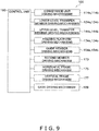
- FIG. 9 is a control block diagram of the box packing device of FIG. 1;
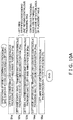
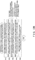
- FIG. 10A is a flowchart for describing operations on the left side of the box packing device of FIG. 1 by which the continuous packaging bags are moved to a collection area;
- FIG. 10B is a flowchart for describing operations on the right side of the box packing device of FIG. 1 by which the continuous packaging bags are moved to the collection area;
- FIG. 11 is a flowchart for describing box packing operations of the box packing device of FIG. 1;
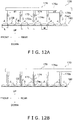
- FIG. 12A is a general left side view, in the vicinity of a box packing mechanism, for describing operations of the box packing device in which the box packing device of FIG. 1 changes the posture of the continuous packaging bags and then puts the continuous packaging bags in a box;
- FIG. 12B is a general left side view, in the vicinity of the box packing mechanism, for describing operations of the box packing device in which the box packing device of FIG. 1 changes the posture of the continuous packaging bags and then puts the continuous packaging bags in the box;
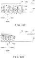
- FIG. 12C is a general left side view, in the vicinity of the box packing mechanism, for describing operations of the box packing device in which the box packing device of FIG. 1 changes the posture of the continuous packaging bags and then puts the continuous packaging bags in the box;
- FIG. 12D is a general left side view, in the vicinity of the box packing mechanism, for describing operations of the box packing device in which the box packing device of FIG. 1 changes the posture of the continuous packaging bags and then puts the continuous packaging bags in the box;
- FIG. 12E is a general left side view, in the vicinity of the box packing mechanism, for describing operations of the box packing device in which the box packing device of FIG. 1 changes the posture of the continuous packaging bags and then puts the continuous packaging bags in the box;
- FIG. 13A is a general left side view, in the vicinity of the box packing mechanism, for describing operations in the box packing device of FIG. 1 when the box packing mechanism is pulled out to the outside of the box after the box packing device has put the continuous packaging bags in the box;
- FIG. 13B is a general left side view, in the vicinity of the box packing mechanism, for describing operations in the box packing device of FIG. 1 when the box packing mechanism is pulled out to the outside of the box after the box packing device has put the continuous packaging bags in the box;
- FIG. 13C is a general left side view, in the vicinity of the box packing mechanism, for describing operations in the box packing device of FIG. 1 when the box packing mechanism is pulled out to the outside of the box after the box packing device has put the continuous packaging bags in the box; and
- FIG. 14 is a drawing for describing the disposition of conveyance units in a case where continuous packaging bag are directly collected in a collection area from two packaging devices.
DETAILED DESCRIPTION
-
A box packing device pertaining to an embodiment of the invention will be described with reference to the drawings.
-
It will be noted that the following embodiment is merely a specific example and is not intended to limit the technical scope of the invention. It will be understood that many changes may be made to the following embodiment without departing from the spirit and scope of the invention.
(1) Overall Configuration
-
A box packing device 100 pertaining to an embodiment of the invention will be described with reference to FIG. 1 to FIG. 4, FIG. 9, and FIG. 12A to FIG. 12E. FIG. 1 is a general plan view of the box packing device 100. FIG. 2 is a general plan view of a lower level portion 100a of the box packing device 100. FIG. 3 is a general left side view of the box packing device 100. FIG. 4 is a general back elevation view of the box packing device 100. FIG. 9 is a control block diagram of the box packing device 100. FIG. 12A to FIG. 12E are general left side views, in the vicinity of a box packing mechanism 170, for describing operations of the box packing device 100 until the box packing device 100 puts continuous packaging bags CB in a box C.
-
It will be noted that in the following description, for convenience of description, expressions such as "front (front elevation)," "rear (back elevation)," "upper," "lower," "left," and "right" are sometimes used to express directions and the like. Unless otherwise specified, the directions indicated by these expressions follow the directions of the arrows in the drawings.
-
Furthermore, in the following description, expressions such as "perpendicular", "orthogonal", "horizontal", "vertical", and "same" are sometimes used to describe directions and positional relationships. These expressions include not only cases where the things they describe are strictly perpendicular, orthogonal, horizontal, vertical, or the same but also cases where the things they describe are substantially perpendicular, orthogonal, horizontal, vertical, or the same.
-
The box packing device 100 is a device that receives supplies of continuous packaging bags CB serving as articles that are objects of box packing and packs in boxes C the continuous packaging bags CB it has received.
-
First, the continuous packaging bags CB, which are objects of box packing by the box packing device 100 of this embodiment, will be described. A "continuous packaging bag" is a bag in which a plurality of small bags B containing packaged product (e.g., a food such as potato chips) are serially connected (see FIG. 12A). In each continuous packaging bag CB, for example, ten small bags B are connected in a row. It will be noted that the number of the small bags B included in each continuous packaging bag CB is arbitrary and is not limited to ten. In each continuous packaging bag CB, the small bags B that are adjacent to each other are interconnected via junctions J. The junctions J are seal portions provided in end portions of each small bag B. The continuous packaging bags CB are manufactured by packaging devices 200A, 200B disposed on the upstream side of the box packing device 100 in the manufacturing process, for example. The box packing device 100 receives supplies of the continuous packaging bags CB from two places (the two packaging devices 200A, 200B) and packs in the boxes C the continuous packaging bags CB it has received.
-
The box packing device 100 mainly has a placement table 160, a pair of conveyance units 110a, 110b, a pair of lower level transfer units 120a, 120b, a pair of ascending/ descending units 130a, 130b, a pair of upper level transfer units 140a, 140b, a pair of guide units 150a, 150b, a box packing mechanism 170, a box placement unit 180, and a control unit 190 (see FIG. 1 to FIG. 4 and FIG. 9). The pair of conveyance units 110a, 110b include a left-side conveyance unit 110a and a right-side conveyance unit 110b. The pair of lower level transfer units 120a, 120b include a left-side lower level transfer unit 120a and a right-side lower level transfer unit 120b. The pair of ascending/ descending units 130a, 130b include a left-side ascending/descending unit 130a and a right-side ascending/descending unit 130b. The pair of upper level transfer units 140a, 140b include a left-side upper level transfer unit 140a and a right-side upper level transfer unit 140b. The pair of guide units 150a, 150b include a left-side guide unit 150a and a right-side guide unit 150b.
-
The structure and operations of the box packing device 100 will be generally described. Details about the structure and operations of the box packing device 100 will be described later.
-
The box packing device 100 of this embodiment has an upper and lower two level structure. The box packing device 100 has a lower level portion 100a and an upper level portion 100b that is disposed above the lower level portion 100a (see FIG. 3 and FIG. 4). The lower level portion 100a is a section to which the conveyance units 110a, 110b convey the continuous packaging bags CB. The lower level portion 100a mainly includes the conveyance surface of the left-side conveyance unit 110a in a later-described left-side first position P1a and the conveyance surface of the right-side conveyance unit 110b in a later-described right-side first position P1b. The upper level portion 100b mainly includes a retention surface 165 on the upper portion of the placement table 160. The placement table 160 is a table on which are placed the continuous packaging bags CB that the box packing mechanism 170 packs in boxes. The retention surface 165 is a surface on which the continuous packaging bags CB are placed and on which the continuous packaging bags CB are temporarily retained. The retention surface 165 includes a left-side retention surface 165bl, a right-side retention surface 165b2, and a collective retention surface 165a that will be described later. The box packing mechanism 170 grips and packs in boxes the continuous packaging bags CB that are placed on the collective retention surface 165a. The continuous packaging bag CB are placed on the left-side retention surface 165b1 and the right-side retention surface 165b2 before they are placed on the collective retention surface 165a. The collective retention surface 165a is disposed between the left-side retention surface 165b1 and the right-side retention surface 165b2.
-
The retention surface 165 does not coincide in the vertical direction with the conveyance surface of the left-side conveyance unit 110a in the left-side first position P1a and the conveyance surface of the right-side conveyance unit 110b in the right-side first position P1b. Specifically, the retention surface 165 is disposed above the conveyance surface of the left-side conveyance unit 110a in the left-side first position P1a and the conveyance surface of the right-side conveyance unit 110b in the right-side first position P1b (see FIG. 3).
-
The left-side conveyance unit 110a conveys to the lower level portion 100a the continuous packaging bags CB that the packaging device 200A supplies. The right-side conveyance unit 110b conveys to the lower level portion 100a the continuous packaging bags CB that the packaging device 200B, which is different from the packaging device 200A, supplies.
-
The left-side lower level transfer unit 120a moves, onto a holding platform 132a of the left-side ascending/descending unit 130a, the continuous packaging bags CB conveyed to the left-side section of the lower level portion 100a. The right-side lower level transfer unit 120b moves, onto a holding platform 132b of the right-side ascending/descending unit 130b, the continuous packaging bags CB conveyed to the right-side section of the lower level portion 100a.
-
The left-side ascending/descending unit 130a moves the holding platform 132a upward to thereby move the continuous packaging bags CB to the neighborhood of the left-side edge portion of the upper level portion 100b (a left-side edge portion 162a of the placement table 160). The right-side ascending/descending unit 130b moves the holding platform 132b upward to thereby move the continuous packaging bags CB to the neighborhood of the right-side edge portion of the upper level portion 100b (a right-side edge portion 162b of the placement table 160).
-
When the left-side ascending/descending unit 130a moves the continuous packaging bags CB to the neighborhood of the left-side edge portion 162a of the placement table 160, the left-side upper level transfer unit 140a moves the continuous packaging bags CB on the holding platform 132a to the left-side retention surface 165b1 disposed on the left side of the placement table 160. Furthermore, when the right-side ascending/descending unit 130b moves the continuous packaging bags CB to the neighborhood of the right-side edge portion 162b of the placement table 160, the right-side upper level transfer unit 140b moves the continuous packaging bags CB on the holding platform 132b to the right-side retention surface 165b2 disposed on the right side of the placement table 160.
-
The left-side guide unit 150a moves the continuous packaging bags CB on the left-side retention surface 165bl to the collective retention surface 165a disposed in the left and right direction middle portion of the placement table 160. The right-side guide unit 150b moves the continuous packaging bags CB on the right-side retention surface 165b2 to the collective retention surface 165a.
-
The box packing mechanism 170 changes, in the front and rear direction, the posture of each of the continuous packaging bags CB which are placed on the collective retention surface 165a of the placement table 160 from a first posture Pos1 (see FIG. 12A) to a second posture Pos2 (see FIG. 12D). In the continuous packaging bag CB in the first posture Pos1, the plural small bags B are disposed extending linearly in a row in the front and rear direction. In the continuous packaging bag CB in the second posture Pos2, at least a part of outer surfaces of each of the small bags B contacts outer surface of other of the small bags B. In other words, the box packing mechanism 170 folds the continuous packaging bags CB, which are placed in a posture in which the plural small bags B on the collective retention surface 165a extend linearly in a row in the front and rear direction, so that the outer surfaces of the small bags B that are arranged adjacent to each other via the junctions J contact each other (see FIG. 12D). In still other words, the box packing mechanism 170 folds the continuous packaging bags CB, which are placed in a posture in which the plural small bags B on the collective retention surface 165a extend linearly in a row in the front and rear direction (see FIG. 12D), into accordion shape. Thereafter, the box packing mechanism 170 packs the continuous packaging bags CB in the folded state in the boxes C on the box placement unit 180 disposed below the placement table 160.
(2) Detailed Configuration
-
The detailed configuration of the box packing device 100 will be described with further reference to FIG. 5A and FIG. 5B and FIG. 6 to FIG. 8. FIG. 5A is a drawing for describing operations of the left-side lower level transfer unit 120a. FIG. 5B is a drawing for describing operations of the right-side lower level transfer unit 120b. FIG. 6 is a drawing for describing operations of the left-side guide unit 150a and the right-side guide unit 150b. FIG. 7 is a drawing for describing moving paths of the continuous packaging bags CB in the lower level of the box packing device 100. FIG. 8 is a drawing for describing moving paths of the continuous packaging bags CB in the upper level of the box packing device 100.
(2-1) Placement Table
-
The placement table 160 is a table on which the continuous packaging bags CB to be packed in boxes by the box packing mechanism 170 are placed and retained. The placement table 160 is substantially rectangular in plan view, though this is not intended to be limiting.
-
The placement table 160 has a left-side edge portion 162a disposed on one end side and a right-side edge portion 162b disposed on the other end side in plan view. In other words, the placement table 160 has the left-side edge portion 162a disposed on one end side and the right-side edge portion 162b disposed on the other end side with respect to a direction orthogonal to the direction (here, the forward direction) in which the continuous packaging bags CB are conveyed by the first conveyance unit and the second conveyance unit in plan view. In other words, the placement table 160 has the left-side edge portion 162a disposed on one end side (the left end side) in the left and right direction in plan view and the right-side edge portion 162b disposed on the other end side (the right end side) in the left and right direction in plan view. The left-side edge portion 162a extends in the front and rear direction along the end portion on the left side of the placement table 160. Furthermore, the right-side edge portion 162b extends in the front and rear direction along the end portion on the right side of the placement table 160.
-
Furthermore, the placement table 160 has on its upper portion the retention surface 165. The retention surface 165 is disposed between the left-side edge portion 162a and the right-side edge portion 162b. The size of the placement table 160 in the front and rear direction is determined so that the continuous packaging bags CB in the state in which the plural small bags B extend linearly in a row in the front and rear direction can be placed on the retention surface 165. The size of the placement table 160 in the left and right direction is determined on the basis of, for example, the number of the continuous packaging bags CB to be placed on the retention surface 165.
-
The placement table 160 is mainly divided into three areas, a left-side retention area 166a, a right-side retention area 166b, and a collection area 164.
-
The left-side retention area 166a is disposed on the left side of the placement table 160. The left-side retention area 166a is disposed between the left-side edge portion 162a and the collective retention surface 165a in plan view. The left-side retention area 166a is an area that temporarily retains the continuous packaging bags CB that the left-side conveyance unit 110a, the left-side lower level transfer unit 120a, the left-side ascending/descending unit 130a, and the left-side upper level transfer unit 140a convey thereto. The section of the retention surface 165 that corresponds to the left-side retention area 166a is called as the left-side retention surface 165b1.
-
The right-side retention area 166b is disposed on the right side of the placement table 160. The right-side retention area 166b is disposed between the right-side edge portion 162b and the collective retention surface 165a in plan view. The right-side retention area 166b is an area that temporarily retains the continuous packaging bags CB that the right-side conveyance unit 110b, the right-side lower level transfer unit 120b, the right-side ascending/descending unit 130b, and the right-side upper level transfer unit 140b convey thereto. The section of the retention surface 165 that corresponds to the right-side retention area 166b is called as the right-side retention surface 165b2.
-
In this embodiment, two continuous packaging bags CB can be temporarily retained in each of the left-side retention area 166a and the right-side retention area 166b. Furthermore, four continuous packaging bags CB can be placed in the collection area 164. However, the number of the continuous packaging bags CB retainable in each of the left-side retention area 166a and the right-side retention area 166b may be appropriately designed. The number of the continuous packaging bags CB retainable in each of the left-side retention area 166a and the right-side retention area 166b may be one or may be three or more. Furthermore, the number of the continuous packaging bags CB placeable in the collection area 164 may be appropriately designed.
-
The collection area 164 is disposed, in the left and right direction, middle portion of the placement table 160. The collection area 164 is disposed between the left-side retention area 166a and the right-side retention area 166b. The section of the retention surface 165 that corresponds to the collection area 164 is called as the collective retention surface 165a. The continuous packaging bags CB retained in the left-side retention area 166a are moved to the collection area 164 by the left-side guide unit 150a, and the continuous packaging bags CB retained in the right-side retention area 166b are moved to the collection area 164 by the right-side guide unit 150b. In other words, in the collection area 164 are collected the continuous packaging bags CB conveyed by the left-side conveyance unit 110a, the left-side lower level transfer unit 120a, the left-side ascending/descending unit 130a, and the left-side upper level transfer unit 140a and the continuous packaging bags CB conveyed by the right-side conveyance unit 110b, the right-side lower level transfer unit 120b, the right-side ascending/descending unit 130b, and the right-side upper level transfer unit 140b.
-
The collection area 164 is at least partially disposed under the box packing mechanism 170. The box packing mechanism 170 packs in the boxes C the continuous packaging bags CB placed on the collective retention surface 165a. The box packing of the continuous packaging bags CB will be generally described.
-
An opening 168 is formed in part of the collective retention surface 165a in the collection area 164. In this embodiment, the opening 168 is formed in the front side of the collective retention surface 165a. Below the opening 168 is disposed the box placement unit 180 on which a box C is placed. When the box packing mechanism 170 packs the continuous packaging bags CB, the box C on the box placement unit 180 is disposed under the opening 168. In other words, when the box packing mechanism 170 packs the continuous packaging bag CB, the box C in which the box packing mechanism 170 packs the continuous packaging bag CB is disposed between the left-side edge portion 162a and the right-side edge portion 162b of the placement table 160 in the left and right direction. A gate 168a that is openable is provided in the opening 168. In this embodiment, the gate 168a is a double gate that slides in the left and right direction. However, the structure of the gate is merely an example, and the structure of the gate may be appropriately selected. It will be noted that the gate 168a is driven by a gate driving mechanism 169. The gate driving mechanism 169 is an air cylinder or a motor, for example, though this is not intended to limit the type of the driving mechanism.
-
When collecting the continuous packaging bag CB on the collective retention surface 165a, the gate 168a is closed. When the box packing mechanism 170 puts the continuous packaging bag CB into the box C, the gate 168a is opened. In a state in which the gate 168a is open, later-described first members 172 and second members 174 of the box packing mechanism 170 and the continuous packaging bags CB gripped by the first members 172 are movable through the opening 168 downward beyond the retention surface 165. The box packing mechanism 170 changes the posture of the continuous packaging bags CB placed on the collective retention surface 165a to the second posture Pos2, grips the continuous packaging bags CB with the second members 174, moves the continuous packaging bags CB through the opening 168, and packs the continuous packaging bags CB in the box C placed on the box placement unit 180. Details about the operations with which the continuous packaging bag CB are packed in boxes by the box packing mechanism 170 will be described later.
(2-2) Left-side Conveyance Unit and Right-side Conveyance Unit
-
The pair of conveyance units 110a, 110b are conveyance devices that receive the continuous packaging bags CB and convey the continuous packaging bags CB that they have received. In this embodiment, the conveyance units 110a, 110b are belt conveyors. However, the type of the conveyance units 110a, 110b is not limited to belt conveyors so long as the conveyance units are devices that can convey the continuous packaging bags CB.
-
The left-side conveyance unit 110a mainly includes a conveyor belt 112a and a conveyance unit driving mechanism 114a that drives the conveyor belt 112a. The right-side conveyance unit 110b mainly includes a conveyor belt 112b and a conveyance unit driving mechanism 114b that drives the conveyor belt 112b. The conveyance unit driving mechanisms 114a, 114b include motors, for example, as drive sources, though this is not intended to be limiting. It will be noted that each of the conveyance units 110a, 110b may have just one conveyor belt or may include plural conveyor belts. The conveyance units 110a, 110b convey the continuous packaging bags CB on the conveyor belts 112a, 112b by driving the conveyor belts 112a, 112b with the conveyance unit driving mechanisms 114a, 114b.
-
The left-side conveyance unit 110a conveys, to the lower level portion 100a of the box packing device 100 that is disposed in a predetermined height position as in FIG. 3, the continuous packaging bags CB that the packaging device 200A supplies. The right-side conveyance unit 110b conveys, to the lower level portion 100a of the box packing device 100 that is disposed in a predetermined height position as in FIG. 3, the continuous packaging bags CB that the packaging device 200B, which is different from the packaging device 200A, supplies.
-
It will be noted that in a case where the conveyance units 110a, 110b directly convey the continuous packaging bags CB to the upper level portion 100b positioned above the lower level portion 100a rather than to the lower level portion 100a of the box packing device 100, the moving distance in the vertical direction becomes relatively large. For that reason, if the continuous packaging bags CB are directly conveyed to the upper level portion 100b, it is necessary to dispose the packaging devices 200A, 200B and the box packing device 100 relatively away from each other. It will be noted that if the inclination of the conveyance units 110a, 110b is increased, it may be possible to inhibit an increase in the distance between the packaging devices 200A, 200B and the packaging device 100. However, to prevent conveyance defects such as sliding of the continuous packaging bags CB during conveyance, there is a limit to the angle of inclination that the conveyance units 110a, 110b can take. Consequently, in a case where the lower level portion 100a is not provided in the box packing device 100, problems arise, such as an increase in the installation space of a system including the packaging devices and the box packing device. On the other hand, in this box packing device 100, the installation space of the system can be reduces because the continuous packaging bags CB are conveyed to the lower level portion 100a under the upper level portion 100b.
-
The pair of conveyance units 110a, 110b are disposed so as to extend parallel to each other in the front and rear direction. The left-side conveyance unit 110a extends forward from the packaging device 200A, and the right-side conveyance unit 110b extends forward from the packaging device 200B. The left-side conveyance unit 110a conveys the continuous packaging bags CB to the left-side section of the lower level portion 100a of the box packing device 100 (the left-side first position P1a) as in FIG. 7. The right-side conveyance unit 110b conveys the continuous packaging bags CB to the right-side section of the lower level portion 100a of the box packing device 100 (the right-side first position P1b) as in FIG. 7. The left-side first position P1a and the right-side first position P1b are disposed apart from each other in the left and right direction as will be understood from FIG. 7. In other words, the left-side conveyance unit 110a and the right-side conveyance unit 110b convey the continuous packaging bags CB serving as articles to places apart from each other.
-
It will be noted that the left-side first position P1a and the right-side first position P1b are preferably disposed under the retention surface 165 of the placement table 160. Furthermore, the box placement unit 180 is disposed between the left-side conveyance unit 110a and the right-side conveyance unit 110b. More specifically, the area of the box placement unit 180 in which the box C is placed is disposed between the left-side conveyance unit 110a and the right-side conveyance unit 110b in plan view. In other words, the area of the box placement unit 180 in which the box C is placed is disposed under the retention surface 165 of the placement table 160. By effectively utilizing the space under the retention surface 165 in this way, the width of the box packing device 100 in the left and right direction can be reduced.
-
It will be noted that if articles are directly conveyed from two packaging devices to the same accumulation area of a box packing device, it becomes necessary, as in FIG. 14, to dispose the conveyance units so as to extend not only in the direction of arrow A leading from the packaging devices to the box packing device but also in the direction of arrow B orthogonal to the direction of arrow A. For that reason, in a configuration such as in FIG. 14, there are problems that the conveyance paths of the conveyance units tend to become long and the installation space of a system including the packaging devices and the box packing device increases. In contrast, in the box packing device 100, the pair of conveyance units 110a, 110b are disposed so as to extend parallel to each other, so the lengths of the conveyance paths of the conveyance units 110a, 110b can be reduced, and an increase in the installation space of the system is easily inhibited.
-
It will be noted that in cases where there is a problem with the continuous packaging bags CB that the left-side conveyance unit 110a conveys, it is preferred that the left-side conveyance unit 110a move the continuous packaging bags CB forward beyond the left-side first position P1a and discharge the continuous packaging bags CB from the front of the left-side conveyance unit 110a to the outside of the box packing device 100 (e.g., to a defective article recovery bin). Furthermore, in cases where there is a problem with the continuous packaging bags CB that the right-side conveyance unit 110b conveys, it is preferred that the right-side conveyance unit 110b move the continuous packaging bags CB forward beyond the right-side first position P1b and discharge the continuous packaging bags CB from the front of the right-side conveyance unit 110b to the outside of the box packing device 100. When the conveyance units 110a, 110b are configured in this way, it is not necessary for workers to manually remove the continuous packaging bags CB from the conveyance units 110a, 110b when there are defective continuous packaging bags CB. It will be noted that "cases where there is a problem with the continuous packaging bags CB" means, for example, cases where a problem is found in the continuous packaging bags CB as a result of an inspection (e.g., a seal inspection or a contamination inspection) of the continuous packaging bags CB by an inspection device not shown in the drawings.
(2-3) Left-side Lower Level Transfer Unit and Right-side Lower Level Transfer Unit
-
The pair of lower level transfer units 120a, 120b move, onto the holding platforms 132a, 132b of the ascending/ descending units 130a, 130b, the continuous packaging bags CB that the conveyance units 110a, 110b have conveyed thereto.
-
The left-side lower level transfer unit 120a includes a lower level transfer member 122a that is movable at least in the left and right direction and a lower level transfer member driving mechanism 124a that drives the lower level transfer member 122a. The right-side lower level transfer unit 120b includes a lower level transfer member 122b that is movable at least in the left and right direction and a lower level transfer member driving mechanism 124b that drives the lower level transfer member 122b. The lower level transfer members 122a, 122b are flat plate-shaped or rod-shaped members that extend in the front and rear direction, though this is not intended to limit their shape. The lower level transfer member driving mechanisms 124a, 124b include motors, for example, as drive sources, though this is not intended to be limiting.
-
The left-side lower level transfer unit 120a transfers, onto the holding platform 132a of the left-side ascending/descending unit 130a disposed on the left side of the left-side conveyance unit 110a, the continuous packaging bag CB on the conveyor belt 112a that the left-side conveyance unit 110a has delivered to the left-side first position P1a. Specifically, the left-side lower level transfer unit 120a pushes leftwardly, with the lower level transfer member 122a, the right side surface of the continuous packaging bag CB that the left-side conveyance unit 110a has delivered to the left-side first position P1a to thereby horizontally move the continuous packaging bag CB onto the holding platform 132a of the left-side ascending/descending unit 130a (to a left-side second position P2a) so that the continuous packaging bag CB is transferred onto the holding platform 132a.
-
The right-side lower level transfer unit 120b transfers, onto the holding platform 132b of the right-side ascending/descending unit 130b disposed on the right side of the right-side conveyance unit 110b, the continuous packaging bag CB on the conveyor belt 112b that the right-side conveyance unit 110b has delivered to the right-side first position P1b. Specifically, the right-side lower level transfer unit 120b pushes rightwardly, with the lower level transfer member 122b, the left side surface of the continuous packaging bag CB that the right-side conveyance unit 110b has delivered to the right-side first position P1b to thereby horizontally move the continuous packaging bag CB onto the holding platform 132b of the right-side ascending/descending unit 130b (to a right-side second position P2b) so that the continuous packaging bag CB is transferred onto the holding platform 132b.
-
It will be noted that it is preferred that the lower level transfer members 122a, 122b move as shown in FIG. 5A and FIG. 5B rather than simply reciprocally move horizontally. Details thereof will be described below.
-
The lower level transfer member 122a is disposed in a position Aa1 (a standby position) just before it moves the continuous packaging bags CB on the conveyor belt 112a to the holding platform 132a of the left-side ascending/descending unit 130a. The position Aa1 is on the right side of the conveyor belt 112a. When the left-side lower level transfer unit 120a moves the continuous packaging bags CB onto the holding platform 132a of the left-side ascending/descending unit 130a, the lower level transfer member 122a horizontally moves in the leftward direction along an outward route R1a1 to a position Aa2. The lower level transfer member 122a horizontally moves from the position Aa1 to the position Aa2 through the neighborhood of the conveyance surface of the conveyor belt 112a. The position Aa2 is in the neighborhood of the right end portion of the left-side ascending/descending unit 130a. Next, the lower level transfer member 122a moves to a position Aa3. Specifically, the lower level transfer member 122a moves upward a predetermined distance to move to the position Aa3. For example, the lower level transfer member 122a moves upward a greater distance than the up and down direction thickness of the continuous packaging bags CB (the thickness of the small bags B) to move to the position Aa3. Next, the lower level transfer member 122a moves in the rightward direction via a return route R1a2, which is disposed above the outward route R1a1, to a position Aa4. For example, the lower level transfer member 122a horizontally moves in the rightward direction along the return route R1a2 from the position Aa3 to the position Aa4. Thereafter, the lower level transfer member 122a moves downward to the position Aa1 (returns to the standby position). Because the lower level transfer member 122a moves in this way, even if there is a continuous packaging bag CB in the left-side first position P1a, the lower level transfer member 122a after having moved a continuous packaging bag CB to the holding platform 132a can return to the position Aa1 (the standby position) without contacting the continuous packaging bag CB in the left-side first position P1a.
-
The lower level transfer member 122b is disposed in a position Ab 1 (a standby position) just before it moves the continuous packaging bags CB on the conveyor belt 112b to the holding platform 132b of the right-side ascending/descending unit 130b. The position Ab1 is on the left side of the conveyor belt 112b. When the right-side lower level transfer unit 120b moves the continuous packaging bags CB onto the holding platform 132b of the right-side ascending/descending unit 130b, the lower level transfer member 122b horizontally moves in the rightward direction along an outward route R1b1 to the position Ab2. The lower level transfer member 122b horizontally moves from the position Ab1 to the position Ab2 through the neighborhood of the conveyance surface of the conveyor belt 112b along the conveyance surface. The position Ab2 is in the neighborhood of the left end portion of the right-side ascending/descending unit 130b. Next, the lower level transfer member 122b moves to a position Ab3. Specifically, the lower level transfer member 122b moves upward a predetermined distance to move to the position Ab3. For example, the lower level transfer member 122b moves upward a greater distance than the up and down direction thickness of the continuous packaging bag CB (the thickness of the small bags B) to move to the position Ab3. Next, the lower level transfer member 122b moves in the leftward direction via a return route R1b2, which is disposed above the outward route R1b1, to a position Ab4. For example, the lower level transfer member 122b horizontally moves in the leftward direction along the return route R1b2 from the position Ab3 to the position Ab4. Thereafter, the lower level transfer member 122b moves downward to the position Ab1 (returns to the standby position). Because the lower level transfer member 122b moves in this way, even if there is a continuous packaging bag CB in the right-side first position Plb, the lower level transfer member 122b after having moved a continuous packaging bag CB to the holding platform 132b can return to the position Ab1 (the standby position) without contacting the continuous packaging bag CB in the right-side first position P1b.
-
It will be noted that the movements of the lower level transfer members 122a, 122b are not limited to the movements described here. However, it is preferred that the lower level transfer members 122a, 122b return from the positions Aa2, Ab2 to the standby positions (the positions Aa1, Ab1) through the return routes R1a2, R1b2 above the continuous packaging bags CB in the first positions P1a, P1b.
(2-4) Left-side Ascending/Descending Unit and Right-side Ascending/Descending Unit
-
The pair of ascending/ descending units 130a, 130b receive and temporarily hold the continuous packaging bags CB that the conveyance units 110a, 110b convey to the first positions P1a, Plb, and move the continuous packaging bags CB upward beyond the height of the conveyance surfaces of the conveyance units 110a, 110b in the first positions P1a, P1b (see the long dashed short dashed line indicated by reference sign PL in FIG. 4). Specifically, the ascending/ descending units 130a, 130b move the continuous packaging bags CB placed on the holding platforms 132a, 132b upward to the height of the retention surface 165 of the placement table 160.
-
The ascending/ descending units 130a, 130b are disposed with the placement table 160 interposed between them. In other words, the retention surface 165 of the placement table 160 is disposed between the left-side ascending/descending unit 130a and the right-side ascending/descending unit 130b. It will be noted that the size of the holding platforms 132a, 132b in the front and rear direction is determined so that the continuous packaging bags CB in the state in which the plural small bags B extend linearly in a row in the front and rear direction can be placed on the holding platforms 132a, 132b.
-
The left-side ascending/descending unit 130a includes the holding platform 132a and a holding platform driving mechanism 134a that drives the holding platform 132a. The holding platform 132a is movable in the up and down direction between a lower position and an upper position. The height position of the upper surface of the holding platform 132a when the holding platform 132a is in the lower position preferably is the same as the height position of the conveyance surface of the left-side conveyance unit 110a in the left-side first position P1a. However, the height position of the upper surface of the holding platform 132a when the holding platform 132a is in the lower position may be lower than the height position of the conveyance surface of the conveyance unit 110a in the left-side first position P1a. The height position of the upper surface of the holding platform 132a when the holding platform 132a is in the upper position preferably is the same as the height position of the retention surface 165 of the placement table 160. However, the height position of the upper surface of the holding platform 132a when the holding platform 132a is in the upper position may be higher than the height position of the retention surface 165 of the placement table 160. The left-side ascending/descending unit 130a is disposed adjacent to the left side of the left-side conveyance unit 110a. In other words, in plan view, the left-side ascending/descending unit 130a is disposed on the side of the left-side conveyance unit 110a opposite the box placement unit 180 (opposite the area of the box placement unit 180 in which the box C is placed). Furthermore, the left-side ascending/descending unit 130a is disposed adjacent to the left side of the placement table 160. The left-side ascending/descending unit 130a moves the holding platform 132a from the lower position to the upper position to thereby upwardly move, to a left-side third position P3a, the continuous packaging bags CB that the left-side lower level transfer unit 120a has moved onto the holding platform 132a (the left-side second position P2a). The left-side third position P3a is a position adjacent to the left-side edge portion 162a of the placement table 160 in plan view.
-
The right-side ascending/descending unit 130b includes the holding platform 132b and a holding platform driving mechanism 134b that drives the holding platform 132b. The holding platform 132b is movable in the up and down direction between a lower position and an upper position. The height position of the upper surface of the holding platform 132b when the holding platform 132b is in the lower position preferably is the same as the height position of the conveyance surface of the right-side conveyance unit 110b in the right-side first position P1b. However, the height position of the upper surface of the holding platform 132b when the holding platform 132b is in the lower position may be lower than the height position of the conveyance surface of the conveyance unit 110b in the right-side first position P1b. The height position of the upper surface of the holding platform 132b when the holding platform 132b is in the upper position preferably is the same as the height position of the retention surface 165 of the placement table 160. However, the height position of the upper surface of the holding platform 132b when the holding platform 132b is in the upper position may be higher than the height position of the retention surface 165 of the placement table 160. The right-side ascending/descending unit 130b is disposed adjacent to the right side of the right-side conveyance unit 110b. In other words, in plan view, the right-side ascending/descending unit 130b is disposed on the side of the right-side conveyance unit 110b opposite the box placement unit 180 (opposite the area of the box placement unit 180 in which the box C is placed). Furthermore, the right-side ascending/descending unit 130b is disposed adjacent to the right side of the placement table 160. The right-side ascending/descending unit 130b moves the holding platform 132b from the lower position to the upper position to thereby upwardly move, to a right-side third position P3b, the continuous packaging bags CB that the right-side lower level transfer unit 120b has moved onto the holding platform 132b (the right-side second position P2b). The right-side third position P3b is a position adjacent to the right-side edge portion 162b of the placement table 160 in plan view.
-
The holding platform driving mechanisms 134a, 134b include air cylinders, for example, as drive sources, though this is not intended to be limiting.
(2-5) Left-side Upper Level Transfer Unit and Right-side Upper Level Transfer Unit
-
The pair of upper level transfer units 140a, 140b move, onto the retention surface 165 of the placement table 160, the continuous packaging bags CB that the ascending/ descending units 130a, 130b have conveyed thereto.
-
The left-side upper level transfer unit 140a is attached to the holding platform 132a of the left-side ascending/descending unit 130a. The left-side upper level transfer unit 140a moves up and down together with the holding platform 132a when the holding platform 132a moves up and down. The right-side upper level transfer unit 140b is attached to the holding platform 132b of the right-side ascending/descending unit 130b. The right-side upper level transfer unit 140b moves up and down together with the holding platform 132b when the holding platform 132b moves up and down.
-
The left-side upper level transfer unit 140a includes an upper level transfer member 142a that is movable at least in the left and right direction and an upper level transfer member driving mechanism 144a that drives the upper level transfer member 142a. The upper level transfer member 142a is disposed above the holding platform 132a. The right-side upper level transfer unit 140b includes an upper level transfer member 142b that is movable at least in the left and right direction and an upper level transfer member driving mechanism 144b that drives the upper level transfer member 142b. The upper level transfer member 142b is disposed above the holding platform 132b.
-
The upper level transfer members 142a, 142b are flat plate-shaped or rod-shaped members that extend in the front and rear direction, though this is not intended to limit their shape. The upper level transfer member driving mechanisms 144a, 144b include air cylinders, for example, as drive sources, though this is not intended to be limiting.
-
Just before the left-side upper level transfer unit 140a moves the continuous packaging bag CB from the holding platform 132a of the left-side ascending/descending unit 130a, the upper level transfer member 142a is disposed in the vicinity of the left edge portion of the holding platform 132a. In other words, just before moving the continuous packaging bag CB from the holding platform 132a, the upper level transfer member 142a is disposed on the left side of the continuous packaging bag CB on the holding platform 132a. When the left-side ascending/descending unit 130a moves the continuous packaging bag CB to the left-side third position P3a, the left-side upper level transfer unit 140a activates the upper level transfer member driving mechanism 144a to push rightwardly, with the upper level transfer member 142a, the left side surface of the continuous packaging bag CB on the holding platform 132a and move the continuous packaging bag CB to the left-side retention surface 165b1 in the left-side retention area 166a of the placement table 160 (to a left-side fourth position P4a). At this time, the upper level transfer member 142a moves from the vicinity of the left edge portion of the holding platform 132a to the vicinity of the left edge portion of the left-side retention area 166a of the placement table 160. It will be noted that in a case where the continuous packaging bags CB that the left-side upper level transfer unit 140a has previously moved are being retained in the left-side retention area 166a, the left-side upper level transfer unit 140a, when moving the continuous packaging bag CB disposed on the leftmost side (the continuous packaging bag CB on the near side) using the upper level transfer member 142a, pushes, via the continuous packaging bag CB on the near side, the continuous packaging bags CB already being retained in the left-side retention area 166a to move it on the left-side retention surface 165b1.
-
Just before the right-side upper level transfer unit 140b moves the continuous packaging bag CB from the holding platform 132b of the right-side ascending/descending unit 130b, the upper level transfer member 142b is disposed in the vicinity of the right edge portion of the holding platform 132b. In other words, just before moving the continuous packaging bag CB from the holding platform 132b, the upper level transfer member 142b is disposed on the right side of the continuous packaging bag CB on the holding platform 132b. When the right-side ascending/descending unit 130b moves the continuous packaging bag CB to the right-side third position P3b, the right-side upper level transfer unit 140b activates the upper level transfer member driving mechanism 144b to push leftwardly, with the upper level transfer member 142b, the right side surface of the continuous packaging bag CB on the holding platform 132b and move the continuous packaging bag CB to the right-side retention surface 165b2 in the right-side retention area 166b of the placement table 160 (to a right-side fourth position P4b). At this time, the upper level transfer member 142b moves from the vicinity of the right edge portion of the holding platform 132b to the vicinity of the right edge portion of the right-side retention area 166b of the placement table 160. It will be noted that in a case where the continuous packaging bags CB that the right-side upper level transfer unit 140b has previously moved are being retained in the right-side retention area 166b, the right-side upper level transfer unit 140b, when moving the continuous packaging bag CB disposed on the rightmost side (the continuous packaging bag CB on the near side) using the upper level transfer member 142b, pushes, via the continuous packaging bag CB on the near side, the continuous packaging bags CB already being retained in the right-side retention area 166b to move it on the right-side retention surface 165b2.
(2-6) Left-side Guide Unit and Right-side Guide Unit
-
The pair of guide units 150a, 150b move the continuous packaging bag CB in the retention areas 166a, 166b to the collection area 164. Furthermore, the pair of guide units 150a, 150b have the function of sandwiching between themselves the plural continuous packaging bags CB on the collective retention surface 165a and aligning the continuous packaging bags CB when the box packing mechanism 170 changes the posture of the continuous packaging bags CB from the first posture Pos1 to the second posture Pos2.
-
The left-side guide unit 150a includes a guide member 152a and a guide member driving mechanism 154a that drives the guide member 152a. The guide member 152a is movable at least in the left and right direction. The right-side guide unit 150b includes a guide member 152b and a guide member driving mechanism 154b that drives the guide member 152b. The guide member 152b is movable at least in the left and right direction. The guide members 152a, 152b are flat plate-shaped or rod-shaped members that extend in the front and rear direction, though this is not intended to limit their shape. The guide member driving mechanisms 154a, 154b include motors, for example, as drive sources, though this is not intended to be limiting.
-
The left-side guide unit 150a moves one or plural continuous packaging bags CB placed in the left-side retention area 166a (the left-side fourth position P4a) onto the collective retention surface 165a of the collection area 164 (to a fifth position P5). The collective retention surface 165a of the collection area 164 is located at the middle portion of the placement table 160 in the left and right direction. Specifically, the left-side guide unit 150a pushes rightwardly, with the guide member 152a, the left side surface of the continuous packaging bag CB placed in the left-side retention area 166a to thereby horizontally move the continuous packaging bag CB on the collective retention surface 165a and move the continuous packaging bag CB to a predetermined position on the collective retention surface 165a. In other words, the guide member 152a of the left-side guide unit 150a moves the continuous packaging bag CB parallel to the collective retention surface 165a on the placement table 160 to thereby move the continuous packaging bag CB to the predetermined position on the collective retention surface 165a. In a case where the left-side guide unit 150a moves plural continuous packaging bags CB, the left-side guide unit 150a pushes rightwardly, with the guide member 152a, the left side surface of the continuous packaging bag CB disposed most leftward among the continuous packaging bags CB placed in the left-side retention area 166a to thereby horizontally move the continuous packaging bags CB on the collective retention surface 165a and move the plural continuous packaging bags CB to the predetermined position on the collective retention surface 165a.
-
The right-side guide unit 150b moves one or plural continuous packaging bags CB placed in the right-side retention area 166b (the right-side fourth position P4b) onto the collective retention surface 165a of the collection area 164 (to the fifth position P5). The collective retention surface 165a of the collection area 164 is located at the middle portion of the placement table 160 in the left and right direction. Specifically, the right-side guide unit 150b pushes leftwardly, with the guide member 152b, the right side surface of the continuous packaging bag CB placed in the right-side retention area 166b to thereby horizontally move the continuous packaging bag CB on the collective retention surface 165a and move the continuous packaging bag CB to a predetermined position on the collective retention surface 165a. In other words, the guide member 152b of the right-side guide unit 150b moves the continuous packaging bag CB parallel to the collective retention surface 165a on the placement table 160 to thereby move the continuous packaging bag CB to the predetermined position on the collective retention surface 165a. In a case where the right-side guide unit 150b moves plural continuous packaging bags CB, the right-side guide unit 150b pushes, in the leftward direction with the guide member 152b, the right side surface of the continuous packaging bag CB disposed most rightward among the continuous packaging bags CB placed in the right-side retention area 166b to thereby horizontally move the continuous packaging bags CB on the collective retention surface 165a and move the plural continuous packaging bags CB to the predetermined position on the collective retention surface 165a.
-
It will be noted that it is preferred that the guide members 152a, 152b move as shown in FIG. 6 rather than simply reciprocally move horizontally.
-
The guide member 152a is disposed in a position Ba1 just before it moves the continuous packaging bag CB in the left-side retention area 166a (the left-side fourth position P4a) to the collection area 164. The position Ba1 is on the left side of the left-side retention area 166a. When the left-side guide unit 150a moves the continuous packaging bag CB to the collection area 164, the guide member 152a horizontally moves in the rightward direction along an outward route R2al to a position Ba2. The guide member 152a horizontally moves from the position Ba1 to the position Ba2 through the neighborhood of the retention surface 165 along the retention surface 165. The position Ba2 is in the neighborhood of the left end portion of the collection area 164. Next, the guide member 152a moves to a position Ba3. Specifically, the guide member 152a moves upward a predetermined distance to move to the position Ba3. More specifically, the guide member 152a moves its lower end portion 152aa upward a predetermined distance to move to the position Ba3. For example, the guide member 152a moves upward a greater distance than the up and down direction thickness of the continuous packaging bag CB (the thickness of the small bags B) to move to the position Ba3. Next, the guide member 152a moves in the leftward direction via a return route R2a2 disposed above the outward route R2a1 to a position Ba4. For example, the guide member 152a horizontally moves in the leftward direction along the return route R2a2 from the position Ba3 to the position Ba4. Thereafter, the guide member 152a moves downward to the position Ba1. Because the guide member 152a moves in this way, when there is a continuous packaging bag CB in the left-side retention area 166a, the guide member 152a after having horizontally moved the continuous packaging bag CB on the collective retention surface 165a can return to the position Ba1 without contacting the continuous packaging bag CB in the left-side retention area 166a. Namely, because the guide member 152a moves in this way, the guide member 152a moves along the outward route R2a1 while horizontally pushing the continuous packaging bag CB to move the continuous packaging bag CB to the collective retention surface 165a and thereafter moves over the continuous packaging bag CB placed in the left-side retention area 166a to return to position Ba1.
-
The guide member 152b is disposed in a position Bb1 just before it moves the continuous packaging bag CB in the right-side retention area 166b (the right-side fourth position P4b) to the collection area 164. The position Bb1 is on the right side of the right-side retention area 166b. When the right-side guide unit 150b moves the continuous packaging bag CB to the collection area 164, the guide member 152b horizontally moves in the leftward direction along an outward route R2b1 to a position Bb2. The guide member 152b horizontally moves from the position Bb1 to the position Bb2 through the neighborhood of the retention surface 165 along the retention surface 165. The position Bb2 is in the neighborhood of the right end portion of the collection area 164. Next, the guide member 152b moves to a position Bb3. Specifically, the guide member 152b moves upward a predetermined distance to move to the position Bb3. More specifically, the guide member 152b moves its lower end portion 152ba upward a predetermined distance to move to the position Bb3. For example, the guide member 152b moves upward a greater distance than the up and down direction thickness of the continuous packaging bag CB (the thickness of the small bags B) to move to the position Bb3. Next, the guide member 152b moves in the rightward direction via a return route R2b2 disposed above the outward route R2b1 to a position Bb4. For example, the guide member 152b horizontally moves in the rightward direction along the return route R2b2 from the position Bb3 to the position Bb4. Thereafter, the guide member 152b moves downward to the position Bb1. Because the guide member 152b moves in this way, when there is a continuous packaging bag CB in the right-side retention area 166b, the guide member 152b after having horizontally moved the continuous packaging bag CB on the collective retention surface 165a can return to the position Bb1 without contacting the continuous packaging bag CB in the right-side retention area 166b. Namely, because the guide member 152b moves in this way, the guide member 152b moves along the outward route R2bl while horizontally pushing the continuous packaging bag CB to move the continuous packaging bag CB to the collective retention surface 165a and thereafter moves over the continuous packaging bag CB placed in the right-side retention area 166b to return to position Bb1.
-
It will be noted that the movements of the guide members 152a, 152b when moving the continuous packaging bags CB from the retention areas 166a, 166b to the collection area 164 are not limited to the movements described here. However, it is preferred that the guide members 152a, 152b return from positions Ba2, Bb2 to the standby positions (positions Ba1, Bb1) through the return routes R2a2, R2b2 above the continuous packaging bags CB that are in the fourth positions P4a, P4b.
-
The movements of the guide member 152a of the left-side guide unit 150a and the guide member 152b of the right-side guide unit 150b when the box packing mechanism 170 packs the continuous packaging bag CB in boxes will be described later.
(2-7) Box Packing Mechanism
-
The box packing mechanism 170 packs in the boxes C the continuous packaging bags CB that are placed on the collective retention surface 165a. Specifically, as mentioned above, the box packing mechanism 170 changes, in the front and rear direction, the posture of each of the plural continuous packaging bags CB, which are placed on the collective retention surface 165a in the first posture Pos1 (see FIG. 12A), into the second posture Pos2 (see FIG. 12D). In this embodiment, in the continuous packaging bag CB in the first posture Pos1, the small bags B extend linearly in a row in the conveyance direction of the first conveyance unit and the second conveyance unit in plan view. In other words, the box packing mechanism 170 folds the continuous packaging bag CB, which are placed in a posture in which the plural small bags B on the collective retention surface 165a extend linearly in a row in the front and rear direction, so that the outer surfaces of the small bags B that are adjacent to each other via the junctions J contact each other (see FIG. 12D). Thereafter, the box packing mechanism 170 packs the continuous packaging bags CB in the second posture Pos2 (in the folded state) in the boxes C on the box placement unit 180 disposed under the placement table 160.
-
The box packing mechanism 170 will now be described in detail.
-
The box packing mechanism 170 mainly includes a support frame 176, plural first members 172, plural second members 174, a horizontal frame driving mechanism 175, a vertical frame driving mechanism 177, and a second member driving mechanism 173 (see FIG. 3 and FIG. 9).
(2-7-1) Support Frame, Horizontal Frame Driving Mechanism, and Vertical Frame Driving Mechanism
-
The support frame 176 is a frame that supports the plural first members 172 and the plural second members 174. The support frame 176 mainly includes a horizontal frame 176a and plural vertical frames 176b.
-
The horizontal frame 176a is attached to a frame (not shown in the drawings) of the box packing device. The horizontal frame 176a is a beam-like member that extends in the front and rear direction. In plan view, the horizontal frame 176a is disposed across generally the whole collection area 164 in the front and rear direction.
-
The plural vertical frames 176b are attached to the horizontal frame 176a so as to line up in the front and rear direction. Specifically, the upper ends of the vertical frames 176b are supported by the horizontal frame 176a. In other words, the vertical frames 176b are supported by the horizontal frame 176a in a state in which they hang down from the horizontal frame 176a. Attached to each vertical frame 176b are one first member 172 and one second member 174, and the vertical frames 176b support the first members 172 and the second members 174. It will be noted that the first members 172 and the second members 174 are not limited to this kind of aspect and may be attached to respectively different vertical frames.
-
At least some of the vertical frames 176b are attached to the horizontal frame 176a so as to be movable in the front and rear direction along the horizontal frame 176a. Specifically, in this embodiment, the vertical frames 176b except for the frontmost vertical frame 176b are attached to the horizontal frame 176a so as to be movable in the front and rear direction. However, the vertical frames 176b are not limited to this, and all the vertical frames 176b may be movable in the front and rear direction. The vertical frames 176b are driven by the vertical frame driving mechanism 177 to move in the front and rear direction. The vertical frame driving mechanism 177 includes a motor, for example, as a drive source, though this is not intended to be limiting. In this embodiment, the plural vertical frames 176b that are movable are driven to move together by one motor. However, each of the plural vertical frames 176b that are movable in the front and rear direction may be independently driven by corresponding individual motors. When the vertical frames 176b move in the front and rear direction, the first members 172 and the second members 174 attached to those vertical frames 176b also move forward and backward.
-
In this embodiment, the plural vertical frames 176b move while maintaining a state in which the distances between the vertical frames 176b that are adjacent are equal to each other. Specifically, before the box packing mechanism 170 starts operations for box packing, the plural vertical frames 176b are disposed a distance d1 apart from each other (see FIG. 12A). The distance d1 is set so that the distances between the second members 174 attached to the vertical frames 176b are generally equal to a distance L between a given junction J in the continuous packaging bag CB and a junction J two junctions away from that given junction J (see FIG. 12A). When the box packing mechanism 170 performs box packing, as described later, the vertical frame driving mechanism 177 moves the vertical frames 176b so that the distances between the vertical frames 176b that are adjacent become smaller. At this time, the vertical frame driving mechanism 177 moves the vertical frames 176b in such a way that the distances between the vertical frames 176b that are adjacent always remain the same (in FIG. 12C, in such a way that the distances become a distance d2 (< d1), and in FIG. 12D, in such a way that the distances become a distance d3 (< d2)).
-
The horizontal frame 176a is configured to be movable in the up and down direction with respect to the frame (not shown in the drawings) of the box packing device 100. The horizontal frame driving mechanism 175 is a mechanism that drives the horizontal frame 176a in the up and down direction. The horizontal frame driving mechanism 175 includes a motor, for example, as a drive source, though this is not intended to be limiting. When the horizontal frame driving mechanism 175 moves the horizontal frame 176a in the up and down direction, the vertical frames 176b attached to the horizontal frame 176a also move in the up and down direction. As a result, when the vertical frames 176b move in the up and down direction, the first members 172 and the second members 174 attached to the vertical frames 176b also move in the up and down direction.
(2-7-2) First Member
-
The first members 172 are members for gripping the continuous packaging bag CB.
-
The first member 172 is attached to each of the vertical frames 176b. The first members 172 are disposed plurally lined up in the front and rear direction. Though this is not intended to be limiting, the first members 172 are flat plate-shaped members having flat surfaces that extend in the left and right direction and the up and down direction.
-
At least some of the plural first members 172 are movable in the front and rear direction. Specifically, the first members 172 attached to the vertical frames 176b that are attached to the horizontal frame 176a so as to be movable in the front and rear direction (in this embodiment, the vertical frames 176b except for the frontmost vertical frame 176b) are movable in the front and rear direction as a result of the vertical frames 176b moving. In the box packing mechanism 170, when the first members 172 move a predetermined distance closer to the first members 172 that are adjacent, at least some of the small bags B of the continuous packaging bag CB become sandwiched and held between the first members 172 that are adjacent. Additionally, when the box packing mechanism 170 packs the continuous packaging bags CB in boxes, the plural first members 172 grip the continuous packaging bags CB by sandwiching and holding at least some of the small bags B of the continuous packaging bags CB between the first members 172 that are adjacent. It will be noted that it is preferred that the rigidity of contact portions 172a of the first members 172 that contact the continuous packaging bag CB be relatively high so that the contact portions 172a do not become deformed and unintentionally drop the continuous packaging bag CB they are gripping. The material of the contact portions 172a of the first members 172 that contact the continuous packaging bag CB may be made of metal or may be made of resin.
-
Furthermore, the plural first members 172 are movable in the up and down direction. Specifically, when the horizontal frame 176a moves in the up and down direction, the vertical frames 176b attached to the horizontal frame 176a also move in the up and down direction, and the first members 172 attached to the vertical frames 176b also move in the up and down direction.
(2-7-3) Second Member and Second Member Driving Mechanism
-
The second members 174 are members mainly for changing the posture of the continuous packaging bag CB.
-
The second members 174 contact from above the continuous packaging bag CB in the first posture Pos1 and change the posture of the continuous packaging bag CB in the front and rear direction so that the continuous packaging bag CB become bended downward at least in one place when seen from the right side or the left side. Specifically, the second members 174 contact from above at least some of the plural junctions J, or the neighborhoods of those junctions J, of the small bags B of the continuous packaging bag CB in the first posture Pos1 and change the posture of the continuous packaging bag CB in the front and rear direction so that the continuous packaging bag CB become bended downward at least in one place when seen from the right side or the left side. In this embodiment, the second members 174 contact from above the frontmost junction J, the junction J between the third small bag B and the fourth small bag B from the front, the junction J between the fifth small bag B and the sixth small bag B from the front, the junction J between the seventh small bag B and the eighth small bag B from the front, and the junction J between the ninth small bag B and the tenth small bag B from the front, or the neighborhoods of those junctions J, and change the posture of the continuous packaging bag CB so that the continuous packaging bag CB become bended downward at the junctions J in the neighborhoods of the places of contact. Furthermore, preferably, the second members 174 change the posture of the continuous packaging bag CB that are in the first posture Pos1 so that the length of the continuous packaging bag CB in the front and rear direction becomes shorter.
-
The second member 174 is attached to each of the vertical frames 176b. In each vertical frame 176b, the second member 174 is disposed on the rear side of the first member 172. In the moving direction (forward) of the first members 172 and the second members 174 when gripping the continuous packaging bag CB, the second member 174 is disposed on the upstream side of the first member 172 in each vertical frame 176b. The second members 174 are disposed plurally lined up in the front and rear direction. Though this is not intended to be limiting, the second members 174 are rod-shaped members that extend in the left and right direction. It will be noted that the rigidity of contact portions 174a of the second members 174 that contact the continuous packaging bag CB is low compared to the rigidity of the contact portions 172a of the first members 172 that contact the continuous packaging bag CB. The contact portions 174a of the second members 174 that contact the continuous packaging bag CB are made of an elastic material whose rigidity is low, such as sponge, foam, or soft rubber, for example.
-
The plural second members 174 are movable in the up and down direction. Specifically, when the horizontal frame 176a moves in the up and down direction, the vertical frames 176b attached to the horizontal frame 176a also move in the up and down direction, and the second members 174 attached to the vertical frames 176b also move in the up and down direction. Furthermore, the second members 174 are movable in the up and down direction, independently of the movement of the horizontal frame 176a, by the second member driving mechanism 173. The second member driving mechanism 173 includes air cylinders, for example, as drive sources, though this is not intended to be limiting. When the air cylinders are driven, the second members 174 move in the up and down direction.
-
Furthermore, at least some of the plural second members 174 are movable in the front and rear direction. Specifically, the second members 174 attached to the vertical frames 176b that are attached to the horizontal frame 176a so as to be movable in the front and rear direction (in this embodiment, the vertical frames 176b except for the frontmost vertical frame 176b) are movable in the front and rear direction together with the movement of the vertical frames 176b.
(2-8) Box Placement Unit
-
The box placement unit 180 is where the boxes C in which the continuous packaging bags CB become packed are placed. The boxes C are placed with their openings facing upward on the box placement unit 180. The box placement unit 180 is disposed between the pair of conveyance units 110a, 110b in plan view. More specifically, the area of the box placement unit 180 in which the boxes C are placed is disposed between the pair of conveyance units 110a, 110b in plan view.
-
The box placement unit 180 includes, for example, a conveyor (not shown in the drawings) that conveys the boxes C. The box placement unit 180 receives empty boxes C from the front side of the box packing device 100, for example, and conveys them under the gate 168a of the placement table 160. The boxes C used for box packing are disposed between the left-side edge portion 162a and the right-side edge portion 162b of the placement table 160. The box placement unit 180 is disposed under the gate 168a of the placement table 160 until the packing of the continuous packaging bags CB in the boxes C is completed. When the packing of the continuous packaging bags CB in the boxes C is completed, the box placement 180 conveys the boxes C that have been filled with the continuous packaging bags CB to the front side of the box packing device 100, for example. It will be noted that the conveyance path of the boxes C in the box placement unit 180 is not limited to the path described here and may be appropriately designed.
(2-9) Control Unit
-
The control unit 190 has a CPU and a memory such as a ROM, a RAM, and/or a flash memory not shown in the drawings. The control unit 190 controls the operations of each part of the box packing device 100 by executing with the CPU a program stored in the memory. It will be noted that the various functions of the control unit 190 are not limited to being realized by software and may be realized by hardware or may be realized by hardware and software working together.
-
The control unit 190 is, as in FIG. 9, electrically connected to various devices including the conveyance unit driving mechanisms 114a, 114b, the lower level transfer member driving mechanisms 124a, 124b, the upper level transfer member driving mechanisms 144a, 144b, the holding platform driving mechanisms 134a, 134b, the guide member driving mechanisms 154a, 154b, the second member driving mechanism 173, the horizontal frame driving mechanism 175, the vertical frame driving mechanism 177, and the gate driving mechanism 169. Furthermore, the control unit 190 is connected to various sensors (not shown in the drawings) provided in the box packing device 100. Furthermore, the control unit 190 may be communicably connected to, for example, the packaging devices 200A, 200B and the inspection device (not shown in the drawings) disposed on the upstream side of the box packing device 100 in the production process.
-
Operations of the box packing device 100 that the control unit 190 controls will be described later.
(3) Movement of Continuous Packaging Bags to Collective Retention Surface
-
Operations when the box packing device 100 moves the continuous packaging bags CB to the collective retention surface 165a will be described with reference to FIG. 10A and FIG. 10B in addition to FIG. 7 and FIG. 8. FIG. 10A is a flowchart for describing operations on the left side of the box packing device 100 by which the continuous packaging bags CB are moved to the collection area 164 of the placement table 160. FIG. 10B is a flowchart for describing operations on the right side of the box packing device 100 by which the continuous packaging bags CB are moved to the collection area 164 of the placement table 160.
-
The operations on the left side of the box packing device 100 by which the continuous packaging bags CB are moved to the collection area 164 of the placement table 160 will be described.
-
When the left-side conveyance unit 110a receives a continuous packaging bag CB from the packaging device 200A, the control unit 190 controls the conveyance unit driving mechanism 114a to convey the continuous packaging bag CB to the left-side first position P1a (step S1a). The control unit 190 controls the running/stopping, the conveyance speed and the like of the conveyance unit driving mechanism 114a to control the conveyance position of the continuous packaging bag CB to the left-side first position P1a on the basis of the result of a detection of the leading end of the continuous packaging bag CB by a sensor not shown in the drawings, for example.
-
Next, the control unit 190 controls the operations of the lower level transfer member driving mechanism 124a of the left-side lower level transfer unit 120a to move the lower level transfer member 122a from position Aa1 to position Aa2 to thereby push the continuous packaging bag CB leftward with the lower level transfer member 122a and move the continuous packaging bag CB onto the holding platform 132a of the left-side ascending/descending unit 130a. In other words, the control unit 190 controls the operations of the lower level transfer member driving mechanism 124a of the left-side lower level transfer unit 120a to push the continuous packaging bag CB leftward with the lower level transfer member 122a and convey the continuous packaging bag CB to the left-side second position P2a (step S2a). It will be noted that the lower level transfer member 122a returns to position Aa1 (the standby position) after it has moved the continuous packaging bag CB to the left-side second position P2a. It will be noted that the control unit 190 may control the conveyance unit driving mechanism 114a of the left-side conveyance unit 110a to start conveying the next continuous packaging bag CB to the left-side first position P1a before the lower level transfer member 122a returns to position Aa1 after it has moved the continuous packaging bag CB to the left-side second position P2a. It will be noted that from the time when the continuous packaging bag CB is transferred to the holding platform 132a in step S2a to until the continuous packaging bag CB is transferred from the holding platform 132a to the placement table 160 in step S4a, the holding platform 132a holds and temporarily retains the continuous packaging bag CB.
-
Next, the control unit 190 controls the operations of the holding platform driving mechanism 134a of the left-side ascending/descending unit 130a to move the holding platform 132a from the lower position to the upper position to thereby convey the continuous packaging bag CB to the left-side third position P3a (an example of a first position) (step S3a).
-
Next, the control unit 190 controls the operations of the upper level transfer member driving mechanism 144a of the left-side upper level transfer unit 140a to push the continuous packaging bag CB rightward with the upper level transfer member 142a and move the continuous packaging bag CB to the left-side retention area 166a of the placement table 160. In other words, the control unit 190 controls the operations of the upper level transfer member driving mechanism 144a of the left-side upper level transfer unit 140a to push the continuous packaging bag CB rightward with the upper level transfer member 142a and convey the continuous packaging bag CB to the left-side fourth position P4a (step S4a). It will be noted that although it is not shown in FIG. 10A, when the left-side upper level transfer unit 140a moves the continuous packaging bag CB on the holding platform 132a of the left-side ascending/descending unit 130a onto the retention surface 165 of the placement table 160, the control unit 190 controls the operations of the holding platform driving mechanism 134a of the left-side ascending/descending unit 130a to move the holding platform 132a from the upper position to the lower position.
-
It will be noted that in a case where more than one continuous packaging bag CB is to be retained in the left-side retention area 166a, the control unit 190 repeats the operations of steps S1a to S4a multiple times, in accordance with the quantity of continuous packaging bag CB to be retained in the left-side retention area 166a, before moving to step S5a.
-
Next, the control unit 190 controls the operations of the guide member driving mechanism 154a of the left-side guide unit 150a to move the guide member 152a from position Ba1 to position Ba2 to thereby push the one or plural continuous packaging bags CB in the left-side fourth position P4a (the left-side retention area 166a) rightward with the guide member 152a, horizontally move the continuous packaging bags CB on the collective retention surface 165a of the placement table 160, and convey the continuous packaging bags CB to the predetermined fifth position P5 (step S5a). For example, though this is not intended to be limiting, the guide member 152a pushes two continuous packaging bags CB in the left-side fourth position P4a rightward to horizontally move the continuous packaging bags CB on the collective retention surface 165a of the placement table 160 and convey the continuous packaging bags CB to the predetermined fifth position P5.
-
It will be noted that the guide member 152a returns to position Ba1 (the standby position) when it moves the continuous packaging bags CB to the fifth position P5 and thereafter the box packing mechanism 170 completes the box packing operations. The operations of the guide member 152a during the box packing operations of the box packing mechanism 170 will be described later. It will be noted that the control unit 190 may control the upper level transfer member driving mechanism 144a of the left-side upper level transfer unit 140a to start conveying the continuous packaging bag CB to the left-side retention area 166a before the guide member 152a returns to position Ba1 after it has moved the continuous packaging bags CB to the fifth position P5.
-
The operations on the right side of the box packing device 100 by which the continuous packaging bags CB are moved to the collection area 164 of the placement table 160 will be described.
-
When the right-side conveyance unit 110b receives a continuous packaging bag CB from the packaging device 200B, the control unit 190 controls the conveyance unit driving mechanism 114b to convey the continuous packaging bag CB to the right-side first position P1b (step S1b). The control unit 190 controls the running/stopping, the conveyance speed and the like of the conveyance unit driving mechanism 114b to control the conveyance position of the continuous packaging bag CB to the right-side first position P1b on the basis of the result of a detection of the leading end of the continuous packaging bag CB by a sensor not shown in the drawings, for example.
-
Next, the control unit 190 controls the operations of the lower level transfer member driving mechanism 124b of the right-side lower level transfer unit 120b to move the lower level transfer member 122b from position Ab1 to position Ab2 to thereby push the continuous packaging bag CB rightward with the lower level transfer member 122b and move the continuous packaging bag CB onto the holding platform 132b of the right-side ascending/descending unit 130b. In other words, the control unit 190 controls the operations of the lower level transfer member driving mechanism 124b of the right-side lower level transfer unit 120b to push the continuous packaging bag CB rightward with the lower level transfer member 122b and convey the continuous packaging bag CB to the right-side second position P2b (step S2b). It will be noted that the lower level transfer member 122b returns to position Ab1 (the standby position) after it has moved the continuous packaging bag CB to the right-side second position P2b. It will be noted that the control unit 190 may control the conveyance unit driving mechanism 114b of the right-side conveyance unit 110b to start conveying the next continuous packaging bag CB to the right-side first position P1b before the lower level transfer member 122b returns to position Ab1 after it has moved the continuous packaging bag CB to the right-side second position P2b.
-
Next, the control unit 190 controls the operations of the holding platform driving mechanism 134b of the right-side ascending/descending unit 130b to move the holding platform 132b from the lower position to the upper position to thereby convey the continuous packaging bag CB to the right-side third position P3b (an example of a second position) (step S3b).
-
Next, the control unit 190 controls the operations of the upper level transfer member driving mechanism 144b of the right-side upper level transfer unit 140b to push the continuous packaging bag CB leftward with the upper level transfer member 142b and move the continuous packaging bag CB to the right-side retention area 166b of the placement table 160. In other words, the control unit 190 controls the operations of the upper level transfer member driving mechanism 144b of the right-side upper level transfer unit 140b to push the continuous packaging bag CB leftward with the upper level transfer member 142b and convey the continuous packaging bag CB to the right-side fourth position P4b (step S4b). It will be noted that although it is not shown in FIG. 10B, when the right-side upper level transfer unit 140b moves the continuous packaging bag CB on the holding platform 132b of the right-side ascending/descending unit 130b onto the retention surface 165 of the placement table 160, the control unit 190 controls the operations of the holding platform driving mechanism 134b of the right-side ascending/descending unit 130b to move the holding platform 132b from the upper position to the lower position.
-
It will be noted that in a case where more than one continuous packaging bag CB is to be retained in the right-side retention area 166b, the control unit 190 repeats the operations of steps S1b to S4b multiple times, in accordance with the quantity of continuous packaging bag CB to be retained in the right-side retention area 166b, before moving to step S5b.
-
Next, the control unit 190 controls the operations of the guide member driving mechanism 154b of the right-side guide unit 150b to move the guide member 152b from position Bb1 to position Bb2 to thereby push the one or plural continuous packaging bag CB in the right-side fourth position P4b (the right-side retention area 166b) leftward with the guide member 152b, horizontally move the continuous packaging bag CB on the collective retention surface 165a of the placement table 160, and convey the continuous packaging bags CB to the predetermined fifth position P5 (step S5b). For example, though this is not intended to be limiting, the guide member 152b pushes two continuous packaging bags CB in the right-side fourth position P4b leftward to horizontally move the continuous packaging bags CB on the collective retention surface 165a of the placement table 160 and convey the continuous packaging bags CB to the predetermined fifth position P5.
-
It will be noted that the guide member 152b returns to position Bb1 (the standby position) when it moves the continuous packaging bags CB to the fifth position P5 and thereafter the box packing mechanism 170 completes the box packing operations. The operations of the guide member 152b during the box packing operations of the box packing mechanism 170 will be described later. It will be noted that the control unit 190 may control the upper level transfer member driving mechanism 144b of the right-side upper level transfer unit 140b to start conveying the continuous packaging bag CB to the right-side retention area 166b before the guide member 152b returns to position Bb1 after it has moved the continuous packaging bag CB to the fifth position P5.
(4) Box Packing Operations
-
The box packing operations of the box packing device 100 will be described with reference to FIG. 11 and FIG. 13A to FIG. 13C in addition to FIG. 12A to FIG. 12E. FIG. 11 is a flowchart for describing the box packing operations of the box packing device 100. FIG. 12A to FIG. 12E are drawings for describing the operations of the box packing device 100 in which the box packing device 100 changes the posture of the continuous packaging bags CB until it puts the continuous packaging bags CB in a box C. FIG. 13A to FIG. 13C are drawings for describing operations in the box packing device 100 when the box packing mechanism 170 is pulled out to the outside of the box C after it has put the continuous packaging bags CB in the box C.
-
First, the state of the box packing device 100 just before the box packing mechanism 170 starts box packing operations will be described. First, in the collection area 164 of the placement table 160, plural (e.g., four) continuous packaging bags CB that are objects of box packing are placed in the first posture Pos1. In this embodiment, it is assumed that two continuous packaging bags CB are moved via the left-side retention area 166a to the collection area 164 and that two continuous packaging bags CB are moved via the right-side retention area 166b to the collection area 164. Furthermore, the guide member 152a of the left-side guide unit 150a that has conveyed the continuous packaging bags CB from the left-side retention area 166a to the collection area 164 is disposed in the neighborhood of the left end of the collection area 164. Furthermore, the guide member 152b of the right-side guide unit 150b that has conveyed the continuous packaging bags CB from the right-side retention area 166b to the collection area 164 is disposed in the neighborhood of the right end of the collection area 164. Furthermore, the plural vertical frames 176b are disposed the distance d1 apart from each other (see FIG. 12A). Furthermore, the continuous packaging bags CB are placed in the collection area 164 in such a way that the second members 174 attached to the vertical frames 176b are disposed in the neighborhoods directly above the frontmost junction J, the junction J between the third small bag B and the fourth small bag B from the front, the junction J between the fifth small bag B and the sixth small bag B from the front, the junction J between the seventh small bag B and the eighth small bag B from the front, and the junction J between the ninth small bag B and the tenth small bag B from the front (see FIG. 12A). Furthermore, the first members 172 and the second members 174 of the box packing mechanism 170 are disposed in positions above the collection area 164 in which they do not contact the continuous packaging bags CB. Furthermore, the gate 168a provided in the placement table 160 is closed.
-
The box packing operations of the box packing device 100 will now be described.
-
When the box packing mechanism 170 starts operations for box packing, first, the control unit 190 controls the operations of the second member driving mechanism 173 to move the second members 174 downward and bring the second members 174 into contact with the continuous packaging bag CB from above (step S11). Specifically, the second members 174 preferably press the continuous packaging bag CB downward with the contact portions 174a (preferably, elastic members) whose rigidity is lower than that of the contact portions 172a of the first members 172 that contact the continuous packaging bag CB. More specifically, the control unit 190 controls the second member driving mechanism 173 to move the second members 174 downward and press downward, with the contact portions 174a of the second members 174, the junctions J of the continuous packaging bag CB in the first posture Pos1 or the neighborhoods of the junctions J. As a result, the continuous packaging bag CB become bended downward at the positions where they are being pressed by the second members 174 in side view (e.g., in left side view) as in FIG. 12B. It will be noted that at this time, at the junctions J of the continuous packaging bag CB not being pressed by the second members 174, the continuous packaging bag CB become bended upward as in FIG. 12B. It will be noted that at the stage when the second members 174 start contacting the continuous packaging bag CB, the first members 172 are positioned in places where they do not contact the continuous packaging bag CB. In other words, the second members 174 start contacting the continuous packaging bag CB before the first members 172 start contacting the continuous packaging bag CB.
-
Next, while pressing the continuous packaging bag CB with the second members 174, the control unit 190 controls the operations of the vertical frame driving mechanism 177 to move the second to fifth vertical frames 176b from the front so that the distances between the vertical frames 176b that are adjacent become smaller. In other words, while pressing the continuous packaging bag CB with the second members 174, the control unit 190 moves the second members 174 that are movable in the front and rear direction so that the distances between the second members 174 in the front and rear direction become smaller (step S12). As a result, the places in the continuous packaging bag CB that are being held down by the second members 174 move closer to each other, and the posture of the continuous packaging bag CB changes to a zigzag shape in left side view as in FIG. 12C. The front and rear direction length of the continuous packaging bag CB in this posture is shorter than the front and rear direction length of the continuous packaging bag CB in the first posture Pos1.
-
Next, the control unit 190 controls the operations of the horizontal frame driving mechanism 175 to move the horizontal frame 176a downward (step S13). In other words, the control unit 190 controls the operations of the horizontal frame driving mechanism 175 to move the first members 172 downward. It will be noted that at this time it is preferred that the control unit 190 control the operations of the horizontal frame driving mechanism 175 so that a distance H between the first members 172 and the placement table 160 (the collective retention surface 165a) becomes equal to or greater than ¼ of a length M of the small bags B. It will be noted that the length M of the small bags B is the length of the small bags B, in the front and rear direction, of the continuous packaging bag CB in the first posture Pos1 in which the plural small bags B are disposed so as to extend linearly in a row in the front and rear direction (see FIG. 12A). In other words, the length M of the small bags B is the distance between the junctions J. Furthermore, it is preferred that the control unit 190 control the operations of the horizontal frame driving mechanism 175 so that the distance H between the first members 172 and the placement table 160 (the collective retention surface 165a) becomes equal to or less than ¾ of the length M of the small bags B. Because the first members 172 are disposed in this position, the first members 172 are less likely to impede the compact folding of the continuous packaging bag CB, and the small bags B can be firmly gripped by the first members 172.
-
Furthermore, in step S13, the control unit 190 controls the operations of the vertical frame driving mechanism 177 to move the second to fifth vertical frames 176b from the front so that the distances between the vertical frames 176b that are adjacent become even smaller. In other words, the control unit 190, in the state in which the first members 172 are moved downward, moves the first members 172 that are movable in the front and rear direction so that the distances between the first members 172 in the front and rear direction become smaller. Specifically, the control unit 190 moves the first members 172 that are movable in the front and rear direction so that the front and rear direction distances between the first members 172 become smaller until the distances between the first members 172 become a predetermined first distance e (step S13; see FIG. 12D). It will be noted that when the distances between the first members 172 have become the first distance e, at least some of the small bags B (in this embodiment, two small bags B) of the continuous packaging bag CB are sandwiched and held between the first members 172 that are adjacent. Furthermore, at this time, the posture of the continuous packaging bag CB is the second posture Pos2 in which at least parts of the outer surface of each of the small bags B contact the outer surfaces of other of the small bags B.
-
Furthermore, in step S13, before the front and rear directions distance between the first members 172 that are adjacent become the first distance e, the control unit 190 controls the operations of the guide member driving mechanism 154a, 154b to sandwich the plural continuous packaging bags CB on the collective retention surface 165a between the guide member 152a of the left-side guide unit 150a and the guide member 152b of the right-side guide unit 150b. Specifically, the guide member 152a and the guide member 152b sandwich the plural continuous packaging bags CB on the collective retention surface 165a in the left and right direction orthogonal to the front and rear direction when the box packing mechanism 170 changes the posture of the continuous packaging bag CB from the first posture Pos1 to the second posture Pos2. Because of this, the plural continuous packaging bags CB easily come into close contact with each other in the left and right direction.
-
Moreover, in step S13, before the front and rear direction distances between the first members 172 that are adjacent become the first distance e, the control unit 190 controls the operations of the second member driving mechanism 173 to move the second members 174 upward to positions in which they do not contact the continuous packaging bag CB (see FIG. 12D).
-
Next, when the small bags B of the continuous packaging bag CB placed on the placement table 160 are sandwiched and held by the first members 172, the control unit 190 controls the gate driving mechanism 169 to open the gate 168a that is closed (step S14).
-
Next, the control unit 190 controls the operations of the horizontal frame driving mechanism 175 to move the horizontal frame 176a downward (step S15). In other words, the control unit 190 moves the horizontal frame 176a downward to thereby move the first members 172 sandwiching and holding the small bags B of the continuous packaging bags CB downward, pass the plural continuous packaging bags CB that the first members 172 are sandwiching and holding through the opening 168 in the placement table 160, and move them into the box C whose opening is facing upward on the box placement unit 180. It will be noted that at this time it is preferred that the small bags B in the frontmost row be guided, so that the small bags B in the frontmost row do not outwardly fall over, by a roller 178 that extends in the left and right direction and is provided below the placement table 160 in the neighborhood of the front edge of the opening 168 in the placement table 160. Furthermore, it is likewise preferred that the small bags B in the rearmost row be guided, so that the small bags B in the rearmost row do not outwardly fall over, by a roller 178 that extends in the left and right direction and is provided below the placement table 160 in the neighborhood of the rear edge of the opening 168 in the placement table 160.
-
Next, the control unit 190 controls the operations of the vertical frame driving mechanism 177 to move the second to fifth vertical frames 176b from the front so that the distances between the vertical frames 176b that are adjacent become greater. In other words, the control unit 190 moves the first members 172 that are movable in the front and rear direction so that the distances between the first members 172 in the front and rear direction become greater (step S16). As a result, the small bags B are no longer sandwiched and held between the first members 172 or at least the force with which the small bags B are sandwiched and held between the first members 172 becomes smaller.
-
Next, the control unit 190 controls the operations of the second member driving mechanism 173 to move the second members 174 downward, bring the second members 174 into contact with the upper surfaces of the continuous packaging bags CB, and hold down the continuous packaging bags CB from above with the second members 174 (step S17). Specifically, the second members 174 press the continuous packaging bags CB downward with the contact portions 174a (preferably, elastic members) whose rigidity is lower than that of the contact portions 172a of the first members 172 that contact the continuous packaging bag CB (see FIG. 13B).
-
In this state, the control unit 190 controls the operations of the horizontal frame driving mechanism 175 to move the horizontal frame 176a upward (step SI8). In other words, the control unit 190 controls the operations of the horizontal frame driving mechanism 175 to move the first members 172 upward, while holding down the continuous packaging bag CB with the second members 174, and pull out the first members 172 from the box C.
-
Next, the control unit 190 controls the operations of the second member driving mechanism 173 to move the second members 174 upward so that the second members 174 no longer contact the continuous packaging bag CB (step S19). Then, finally, the support frame 176, the plural first members 172, and the plural second members 174 of the box packing mechanism 170 return to the state they were in before the start of the box packing operations of the box packing mechanism 170.
-
Next, the control unit 190 controls the gate driving mechanism 169 to close the gate 168a that is open (step S20).
-
It will be noted that although it is not shown in the drawings, the box C in which the continuous packaging bags CB have been packed is conveyed to the outside of the box packing device 100 by the box placement unit 180. With this, the series of box packing operations is completed.
-
It will be noted that the aspects of the box packing operations described here are merely an example and can be appropriately changed.
-
For example, here, the box packing of the continuous packaging bags CB is performed only one time with respect to the box C, but instead of this, the series of box packing operations from step S11 to step S20 may be performed two or more times with respect to one box C.
-
Furthermore, the order in which steps S11 to S20 are executed may be replaced unless such a replacement causes contradiction. Furthermore, plural steps may be executed simultaneously unless such a change causes contradiction.
(5) Characteristics
(5-1)
-
The box packing device 100 of this embodiment includes the placement table 160, a first conveyance unit, a second conveyance unit, a first moving unit, a second moving unit, and the box packing mechanism 170. It will be noted that in this embodiment the first conveyance unit includes the left-side conveyance unit 110a, the left-side lower level transfer unit 120a, and the left-side ascending/descending unit 130a. The second conveyance unit includes the right-side conveyance unit 110b, the right-side lower level transfer unit 120b, and the right-side ascending/descending unit 130b. The first moving unit includes the left-side upper level transfer unit 140a and the left-side guide unit 150a. The second moving unit includes the right-side upper level transfer unit 140b and the right-side guide unit 150b. The placement table 160 has on its upper portion the collective retention surface 165a serving as an example of a placement surface on which the continuous packaging bags CB are placed. The placement table 160 has the left-side edge portion 162a disposed on one end side and the right-side edge portion 162b disposed on the other end side of the placement table 160 with respect to the left-side edge portion 162a. The left-side edge portion 162a is an example of a first edge portion, and the right-side edge portion 162b is an example of a second edge portion. The first conveyance unit conveys the continuous packaging bag CB to the left-side third position P3a serving as an example of a first position adjacent to the left-side edge portion 162a of the placement table 160 in plan view. The second conveyance unit conveys the continuous packaging bag CB to the right-side third position P3b serving as an example of a second position adjacent to the right-side edge portion 162b of the placement table 160 in plan view. In this embodiment, the first conveyance unit and the second conveyance unit convey the continuous packaging bag CB parallel to each other (here, forward) in plan view. The first moving unit moves, to the collective retention surface 165a, the continuous packaging bag CB that the first conveyance unit conveys to the left-side third position P3a. The second moving unit moves, to the collective retention surface 165a, the continuous packaging bag CB that the second conveyance unit conveys to the right-side third position P3b. The box packing mechanism 170 packs in the box C the continuous packaging bags CB that are placed on the collective retention surface 165a.
-
In this box packing device 100, the continuous packaging bags CB which the packaging device 200A supplies and which the first conveyance unit conveys and the continuous packaging bags CB which the packaging device 200B, which is separate from the packaging device 200A, supplies and which the second conveyance unit conveys are moved from both sides of the placement table 160 to the collective retention surface 165a. For that reason, the installation space of a system including the packaging devices 200A, 200B and the box packing device 100 can be reduced compared to a case where the two packaging devices 200A, 200B directly convey the continuous packaging bag CB to the collective retention surface 165a.
(5-2)
-
In the box packing device 100 of this embodiment, the box C in which the box packing mechanism 170 packs the continuous packaging bags CB are disposed between the left-side edge portion 162a and the right-side edge portion 162b in the left and right direction.
-
In this box packing device 100, since the box C for box packing is disposed between the left-side edge portion 162a and the right-side edge portion 162b of the placement table 160, an increase in the left and right direction width of the box packing device 100 can be inhibited.
(5-3)
-
In the box packing device 100 of this embodiment, the first moving unit includes the guide member 152a serving as an example of a first guide member that moves the continuous packaging bag CB parallel to the collective retention surface 165a on the placement table 160. The second moving unit includes the guide member 152b serving as an example of a second guide member that moves the continuous packaging bag CB parallel to the collective retention surface 165a on the placement table 160. Preferably, the guide members 152a, 152b horizontally move the continuous packaging bag CB.
-
This box packing device 100 moves the continuous packaging bags CB parallel to the collective retention surface 165a, so compared to a structure that grips and lift the continuous packaging bag CB, the moving units can be simplified in structure and can move the continuous packaging bags CB in a short amount of time to the collective retention surface 165a.
(5-4)
-
In the box packing device 100 of this embodiment, the guide member 152a horizontally moves along the outward route R2a1 serving as an example of a first route from a position Ba1 serving as a first standby position to thereby horizontally move the continuous packaging bag CB on the collective retention surface 165a. Thereafter, the guide member 152a moves the lower end portion 152aa of the guide member 152a upward a predetermined distance and returns via the return route R2a2 serving as an example of a second route disposed above the outward route R2a1 to the position Ba1. The guide member 152b horizontally moves along the outward route R2b1 serving as an example of a third route from a position Bb1 serving as a second standby position to thereby horizontally move the continuous packaging bag CB on the collective retention surface 165a. Thereafter, the guide member 152b moves the lower end portion 152ba of the guide member 152b upward a predetermined distance and returns via the return route R2b2 serving as an example of a fourth route disposed above the outward route R2b1 to the position Bb1.
-
In this box packing device 100, the guide members 152a, 152b horizontally move from the standby positions Ba1, Bb1 to thereby move the continuous packaging bags CB to the collective retention surface 165a and thereafter move over the horizontal moving routes (the outward routes R2a1, R2b1) to return to the standby positions Ba1, Bb1. For that reason, in this box packing device 100, the guide members 152a, 152b can be kept from contacting the continuous packaging bags CB when the continuous packaging bags CB are moved to the placement table 160 before the guide members 152a, 152b return to the standby positions Ba1, Bb1. For that reason, in this box packing device 100, the continuous packaging bag CB can be moved to the placement table 160 in advance before the guide members 152a, 152b return to the standby positions Ba1, Bb1, and the throughput of the box packing device 100 can be improved.
(5-5)
-
In this box packing device 100, the guide member 152a and the guide member 152b sandwich between themselves a plurality of the continuous packaging bags CB on the collective retention surface 165a.
-
This box packing device 100 sandwiches the continuous packaging bags CB with the guide member 152a and the guide member 152b, so the plural continuous packaging bags CB on the collective retention surface 165a can be aligned, and occurrence of problems in the box packing by the box packing mechanism 170 that arise due to misalignment of the continuous packaging bags CB can be reduced. Furthermore, in this box packing device 100, the continuous packaging bags CB can be brought into close contact with each other as a result of the plural continuous packaging bags CB being sandwiched by the guide member 152a and the guide member 152b, so it is easy to improve the fill rate of the continuous packaging bags CB in the box C during box packing.
(5-6)
-
In this box packing device 100, each of the continuous packaging bags CB includes a plurality of the small bags B connected in a row. The box packing mechanism 170 changes, in a first direction, the posture of each of the continuous packaging bags CB which are placed on the collective retention surface 165a from the first posture Pos1 to the second posture Pos2. In the continuous packaging bag CB in the first posture Pos1, the plural small bags B are disposed extending linearly in a row along the first direction. In the continuous packaging bag CB in the second posture Pos2, at least a part of the outer surface of each of the small bags B contacts the outer surface of other of the small bags B. The guide member 152a and the guide member 152b sandwich the plural continuous packaging bags CB on the collective retention surface 165a in the left and right direction orthogonal to the first direction when the box packing mechanism 170 changes the posture of the continuous packaging bag CB from the first posture Pos1 to the second posture Pos2. The first direction here is the front and rear direction. Here, the first direction is parallel to the conveyance direction in which the first conveyance unit and the second conveyance unit convey the continuous packaging bags CB.
-
In this box packing device 100, when changing the posture of the continuous packaging bags CB so as to fold the continuous packaging bags CB in the first direction (the longitudinal direction in which the small bags aligns) to raise the fill rate in the boxes C, the guide members 152a, 152b sandwich the continuous packaging bags CB in a direction orthogonal to the first direction. For that reason, in this box packing device 100, the continuous packaging bag CB can be neatly folded, and it is easy to improve the fill rate of the continuous packaging bags CB in the box C during box packing.
-
It will be noted that here the guide members 152a, 152b sandwich the continuous packaging bags CB after the continuous packaging bags CB are held down by the second members 174 rather than the guide members 152a, 152b sandwich the continuous packaging bags CB in advance. As a result, the occurrence of problems, such as the continuous packaging bag CB is damaged due to the plural continuous packaging bags CB overlapping each other when the continuous packaging bags CB are sandwiched by the guide members 152a, 152b, can be reduced.
(5-7)
-
In this box packing device 100, the placement table 160 has the left-side retention area 166a serving as an example of a first retention section and the right-side retention area 166b serving as an example of a second retention section. The left-side retention area 166a is disposed between the left-side edge portion 162a and the collective retention surface 165a in the left and right direction in plan view. The right-side retention area 166b is disposed between the right-side edge portion 162b and the collective retention surface 165a in the left and right direction in plan view. The first moving unit includes the upper level transfer member 142a serving as an example of a first transfer member that moves, to the left-side retention area 166a, the continuous packaging bag CB that the first conveyance unit conveys to the left-side third position P3a. The second moving unit includes the upper level transfer member 142b serving as an example of a second transfer member that moves, to the right-side retention area 166b, the continuous packaging bag CB that the second conveyance unit conveys to the right-side third position P3b.
-
This box packing device 100 can, while moving the continuous packaging bag CB to the collective retention surface 165a, prepare in the retention areas 166a, 166b the continuous packaging bags CB to be moved next to the collective retention surface 165a. For that reason, in this box packing device 100, throughput can be improved.
(5-8)
-
In this box packing device 100, the guide member 152a moves along the outward route R2a1 while horizontally pushing the continuous packaging bag CB to thereby move the continuous packaging bag CB to the collective retention surface 165a. Thereafter, the guide member 152a moves over the continuous packaging bag CB placed in the left-side retention area 166a to return to position Ba1. The guide member 152b moves along the outward route R2b1 while horizontally pushing the continuous packaging bag CB to thereby move the continuous packaging bag CB to the collective retention surface 165a. Thereafter, the guide member 152b moves over the continuous packaging bag CB placed in the right-side retention area 166b to return to position Bb1.
-
For that reason, in this box packing device 100, the continuous packaging bags CB can be moved in advance to the retention areas 166a, 166b before the guide members 152a, 152b return to the standby positions Ba1, Bb1, and the throughput of the box packing device 100 can be therefore improved.
(5-9)
-
In this box packing device 100, the placement table 160 extends in the left and right direction, which is one example of a second direction, from the left-side edge portion 162a to the right-side edge portion 162b. In other words, the retention surface 165 of the placement table 160 extends in the left and right direction, which is one example of a second direction, from the left-side edge portion 162a to the right-side edge portion 162b. The second direction (i.e., the left and right direction) is orthogonal to the direction (i.e., the forward direction) in which the continuous packaging bags CB are conveyed by the first conveyance unit and the second conveyance unit in plan view.
-
By giving the placement table 160 this kind of disposition, it is not necessary to convey the continuous packaging bag CB along complex routes, and the installation space of a system including the packaging devices 200A, 200B and the box packing device 100 can be reduced.
(6) Example Modifications
-
Example modifications of the above embodiment will be described below. It will be noted that the content of each example modification described below may be combined with some or all of the content of another example modification to the extent that they are not incompatible with each other.
(6-1) Example Modification A
-
In the above embodiment, the object of box packing by the box packing device 100 is the continuous packaging bag CB, but it is not limited to this. The objects of box packing by the box packing device 100 may be ordinal bags (not continuous packaging bags).
(6-2) Example Modification B
-
In the above embodiment, the box packing device 100 has an upper and lower two level structure, but the box packing device 100 may have a single level structure.
-
For example, the box packing device 100 does not need to have the lower level transfer units 120a, 120b and the ascending/ descending units 130a, 130b. Additionally, in the box packing device 100, the left-side conveyance unit 110a may directly convey the continuous packaging bag CB to the left-side retention area 166a of the placement table 160, and the right-side conveyance unit 110b may directly convey the continuous packaging bag CB to the right-side retention area 166b of the placement table 160.
(6-3) Example Modification C
-
The box packing mechanism 170 of the box packing device 100 is not limited to the configuration of the above embodiment. For example, the box packing mechanism 170 may be a mechanism that uses suckers to suck hold of, grip, and move the continuous packaging bags CB that are placed on the collective retention surface 165a and pack them in the boxes C.
(6-4) Example Modification D
-
In the above embodiment, the retention areas 166a, 166b and the collection area 164 are provided in the placement table 160 that is integrally formed, but the placement table 160 is not limited to this. For example, a member configuring the left-side retention area 166a, a member configuring the right-side retention area 166b, and a member configuring the collection area 164 may be combined to function as the placement table 160.
(6-5) Example Modification E
-
In the box packing device 100 of the above embodiment, the box packing mechanism 170 packs in boxes the continuous packaging bags CB that the first moving unit and the second moving unit move to the collective retention surface 165a. However, it is not limited to this, and it is preferred that the box packing mechanism 170 be capable of packing the continuous packaging bag CB that only the first moving unit moves to the collective retention surface 165a or the continuous packaging bag CB that only the second moving unit moves to the collective retention surface 165a. For example, it is preferred that the box packing mechanism 170 be capable of packing, in the boxes C in the way described above, four continuous packaging bags CB that only the first moving unit moves to the collection area 164.
-
When the box packing device 100 is configured in this way, box packing can be continued without stopping the box packing device 100 even in a case where one of the packaging device 200A that supplies the continuous packaging bag CB to the first conveyance unit and the packaging device 200B that supplies the continuous packaging bag CB to the second conveyance unit stops for some reason.
(6-6) Example Modification F
-
In the box packing device 100 of the above embodiment, the first conveyance unit and the first moving unit convey the same number of continuous packaging bags CB to the collective retention surface 165a as the number of continuous packaging bags CB that the second conveyance unit and the second moving unit convey, but the box packing device 100 is not limited to this. For example, the first conveyance unit and the first moving unit may convey a different number of continuous packaging bags CB to the collective retention surface 165a than the number of continuous packaging bags CB that the second conveyance unit and the second moving unit convey. For example, in the case of packing four continuous packaging bags CB in the box C, the first conveyance unit and the first moving unit may convey three continuous packaging bags CB to the collective retention surface 165a, and the second conveyance unit and the second moving unit may convey one continuous packaging bag CB to the collective retention surface 165a.
(6-7) Example Modification G
-
In the box packing device 100 of the above embodiment, the first moving unit and the second moving unit convey continuous packaging bags CB of the same type to the collective retention surface 165a. However, the box packing device 100 is not limited to this, and the first moving unit may move, to the collective retention surface 165a, a first type of the continuous packaging bag CB that the first conveyance unit conveys to the left-side third position P3a, and the second moving unit may move, to the collective retention surface 165a, a second type of the continuous packaging bag CB that the second conveyance unit conveys to the right-side third position P3b. The second type of the continuous packaging bag CB is different from the first type of the continuous packaging bag CB.
-
When the box packing device 100 is configured in this way, plural types of the continuous packaging bags CB can be packed in one box C.
Industrial Applicability
-
This invention can be widely applied to, and is useful in, box packing devices that pack bags in boxes.
Reference Signs List
-
- 100
- Box Packing Device
- 110a
- Left-side Conveyance Unit (First Conveyance Unit)
- 110b
- Right-side Conveyance Unit (Second Conveyance Unit)
- 120a
- Left-side Lower Level Transfer Unit (First Conveyance Unit)
- 120b
- Right-side Lower Level Transfer Unit (Second Conveyance Unit)
- 130a
- Left-side Ascending/Descending Unit (First Conveyance Unit)
- 130b
- Right-side Ascending/Descending Unit (Second Conveyance Unit)
- 140a
- Left-side Upper Level Transfer Unit (First Moving Unit)
- 140b
- Right-side Upper Level Transfer Unit (Second Moving Unit)
- 142a
- Upper Level Transfer Member (First Transfer Member)
- 142b
- Upper Level Transfer Member (Second Transfer Member)
- 150a
- Left-side Guide Unit (First Moving Unit)
- 150b
- Right-side Guide Unit (Second Moving Unit)
- 152a
- Guide Member (First Guide Member)
- 152b
- Guide Member (Second Guide Member)
- 160
- Placement Table
- 162a
- Left-side Edge Portion (First Edge Portion)
- 162b
- Right-side Edge Portion (Second Edge Portion)
- 165a
- Collective Retention Surface (Placement Surface)
- 166a
- Left-side Retention Area (First Retention Section)
- 166b
- Right-side Retention Area (Second Retention Section)
- 170
- Box Packing Mechanism
- Ba1
- Position (First Standby Position)
- Bb1
- Position (Second Standby Position)
- B
- Small Bags
- C
- Box
- CB
- Continuous Packaging Bag (Bag)
- P3a
- Left-side Third Position (First Position)
- P3b
- Right-side Third Position (Second Position)
- Pos1
- First Posture
- Pos2
- Second Posture
- R2a1
- Outward Route (First Route)
- R2a2
- Return Route (Second Route)
- R2b1
- Outward Route (Third Route)
- R2b2
- Return Route (Fourth Route)
Citation List
Patent Literature
-
Patent Document 1:
JP-ANo. 2004-352287