EP3851334B1 - Electrical connection box and cover structure for electrical connection part - Google Patents
Electrical connection box and cover structure for electrical connection part Download PDFInfo
- Publication number
- EP3851334B1 EP3851334B1 EP21151335.3A EP21151335A EP3851334B1 EP 3851334 B1 EP3851334 B1 EP 3851334B1 EP 21151335 A EP21151335 A EP 21151335A EP 3851334 B1 EP3851334 B1 EP 3851334B1
- Authority
- EP
- European Patent Office
- Prior art keywords
- cover member
- bearing
- electrical connection
- rotation shaft
- opening
- Prior art date
- Legal status (The legal status is an assumption and is not a legal conclusion. Google has not performed a legal analysis and makes no representation as to the accuracy of the status listed.)
- Active
Links
Images


Classifications
-
- B—PERFORMING OPERATIONS; TRANSPORTING
- B60—VEHICLES IN GENERAL
- B60R—VEHICLES, VEHICLE FITTINGS, OR VEHICLE PARTS, NOT OTHERWISE PROVIDED FOR
- B60R16/00—Electric or fluid circuits specially adapted for vehicles and not otherwise provided for; Arrangement of elements of electric or fluid circuits specially adapted for vehicles and not otherwise provided for
- B60R16/02—Electric or fluid circuits specially adapted for vehicles and not otherwise provided for; Arrangement of elements of electric or fluid circuits specially adapted for vehicles and not otherwise provided for electric constitutive elements
- B60R16/023—Electric or fluid circuits specially adapted for vehicles and not otherwise provided for; Arrangement of elements of electric or fluid circuits specially adapted for vehicles and not otherwise provided for electric constitutive elements for transmission of signals between vehicle parts or subsystems
- B60R16/0238—Electrical distribution centers
-
- H—ELECTRICITY
- H02—GENERATION; CONVERSION OR DISTRIBUTION OF ELECTRIC POWER
- H02G—INSTALLATION OF ELECTRIC CABLES OR LINES, OR OF COMBINED OPTICAL AND ELECTRIC CABLES OR LINES
- H02G3/00—Installations of electric cables or lines or protective tubing therefor in or on buildings, equivalent structures or vehicles
- H02G3/02—Details
- H02G3/08—Distribution boxes; Connection or junction boxes
- H02G3/16—Distribution boxes; Connection or junction boxes structurally associated with support for line-connecting terminals within the box
-
- H—ELECTRICITY
- H02—GENERATION; CONVERSION OR DISTRIBUTION OF ELECTRIC POWER
- H02G—INSTALLATION OF ELECTRIC CABLES OR LINES, OR OF COMBINED OPTICAL AND ELECTRIC CABLES OR LINES
- H02G3/00—Installations of electric cables or lines or protective tubing therefor in or on buildings, equivalent structures or vehicles
- H02G3/02—Details
- H02G3/08—Distribution boxes; Connection or junction boxes
- H02G3/14—Fastening of cover or lid to box
-
- B—PERFORMING OPERATIONS; TRANSPORTING
- B60—VEHICLES IN GENERAL
- B60R—VEHICLES, VEHICLE FITTINGS, OR VEHICLE PARTS, NOT OTHERWISE PROVIDED FOR
- B60R16/00—Electric or fluid circuits specially adapted for vehicles and not otherwise provided for; Arrangement of elements of electric or fluid circuits specially adapted for vehicles and not otherwise provided for
- B60R16/02—Electric or fluid circuits specially adapted for vehicles and not otherwise provided for; Arrangement of elements of electric or fluid circuits specially adapted for vehicles and not otherwise provided for electric constitutive elements
- B60R16/0207—Wire harnesses
- B60R16/0215—Protecting, fastening and routing means therefor
-
- E—FIXED CONSTRUCTIONS
- E05—LOCKS; KEYS; WINDOW OR DOOR FITTINGS; SAFES
- E05D—HINGES OR SUSPENSION DEVICES FOR DOORS, WINDOWS OR WINGS
- E05D1/00—Pinless hinges; Substitutes for hinges
- E05D1/06—Pinless hinges; Substitutes for hinges consisting of two easily-separable parts
-
- E—FIXED CONSTRUCTIONS
- E05—LOCKS; KEYS; WINDOW OR DOOR FITTINGS; SAFES
- E05D—HINGES OR SUSPENSION DEVICES FOR DOORS, WINDOWS OR WINGS
- E05D7/00—Hinges or pivots of special construction
- E05D7/10—Hinges or pivots of special construction to allow easy separation or connection of the parts at the hinge axis
- E05D7/1061—Hinges or pivots of special construction to allow easy separation or connection of the parts at the hinge axis in a radial direction
- E05D7/1066—Hinges or pivots of special construction to allow easy separation or connection of the parts at the hinge axis in a radial direction requiring a specific angular position
-
- H—ELECTRICITY
- H02—GENERATION; CONVERSION OR DISTRIBUTION OF ELECTRIC POWER
- H02G—INSTALLATION OF ELECTRIC CABLES OR LINES, OR OF COMBINED OPTICAL AND ELECTRIC CABLES OR LINES
- H02G3/00—Installations of electric cables or lines or protective tubing therefor in or on buildings, equivalent structures or vehicles
- H02G3/02—Details
- H02G3/08—Distribution boxes; Connection or junction boxes
- H02G3/081—Bases, casings or covers
-
- E—FIXED CONSTRUCTIONS
- E05—LOCKS; KEYS; WINDOW OR DOOR FITTINGS; SAFES
- E05Y—INDEXING SCHEME ASSOCIATED WITH SUBCLASSES E05D AND E05F, RELATING TO CONSTRUCTION ELEMENTS, ELECTRIC CONTROL, POWER SUPPLY, POWER SIGNAL OR TRANSMISSION, USER INTERFACES, MOUNTING OR COUPLING, DETAILS, ACCESSORIES, AUXILIARY OPERATIONS NOT OTHERWISE PROVIDED FOR, APPLICATION THEREOF
- E05Y2999/00—Subject-matter not otherwise provided for in this subclass
-
- H—ELECTRICITY
- H02—GENERATION; CONVERSION OR DISTRIBUTION OF ELECTRIC POWER
- H02G—INSTALLATION OF ELECTRIC CABLES OR LINES, OR OF COMBINED OPTICAL AND ELECTRIC CABLES OR LINES
- H02G3/00—Installations of electric cables or lines or protective tubing therefor in or on buildings, equivalent structures or vehicles
- H02G3/02—Details
- H02G3/08—Distribution boxes; Connection or junction boxes
- H02G3/086—Assembled boxes
Definitions
- the present invention relates to an electrical connection box and a cover structure for an electrical connection part.
- Vehicles such as automobiles are conventionally equipped with various electric connection objects and have housings enclosing electrical connection parts relating to these electric connection objects.
- a housing has a work opening that enables work relating to the electrical connection parts (e.g., attachment and detachment of the electric connection object) when required.
- the housing thus has a cover for closing the work opening.
- Japanese Patent Application Laid-open No. 2008-113534 discloses this type of housing.
- the cover may be molded integrally with the housing and other parts such as a living hinge.
- the cover may be molded as a part separate from the housing (a cover member) and then coupled to the housing by a hinge structure.
- the hinge structure is configured to allow the cover member to rotate between an open position and a closed position relative to the work opening. It is desirable that the hinge structure be configured so that the cover member is not detached from the housing in any position between the open position and the closed position. Further prior art is known from documents US 5 979 016 A and GB 2 264 105 A .
- an electrical connection box and a cover structure for an electrical connection part includes a housing member having an opening and an interior space connecting to the opening, the interior space accommodating an electrical connection part; a first cover member including a closure section that closes the opening and has a work opening enabling work relating to the electrical connection part; a second cover member configured to close the work opening; a hinge structure configured to allow the second cover member to rotate within a rotational range between an open position and a closed position relative to the work opening; and a detachment prevention structure configured to disable detachment of the second cover member from the first cover member in an assembled state in which the first cover member to which the second cover member is coupled is coupled to the housing member, wherein the hinge structure includes a rotation shaft provided on the closure section, an arc-shaped cantilever bearing provided on the second cover member, the bearing having an inner circumference surface supporting the rotation shaft, and a through hole formed in the closure section, the through hole accommodating the rotation shaft and being configured to allow the
- the rotational retaining section is formed on the outer circumferential surface of the free end of the bearing.
- the bearing has an insertion opening inserting the rotation shaft to the shaft support position in a direction perpendicular to the axial direction, and the insertion opening opens in a direction intersecting a plane direction of a contact plane between the work opening and the second cover member.
- FIGS. 1 to 11 one embodiment of an electrical connection box and a cover structure for an electrical connection part according to the present invention is now described.
- a cover structure 1 is applied to an electric component housing B for accommodating an electric component ( FIGS. 1 to 8 ).
- the electric component housing B may be an electrical connection box or a conductive module, such as a bus bar module.
- an insulative housing encloses an electronic component serving as an electric connection object, to which another electric connection object, which may be a conductive member (e.g., a conductive bus bar) or an electric wire, is electrically connected within the housing.
- an electrical connection part may be a physical and electrical connection part between the electronic component and the conductive member, a physical and electrical connection part between the electronic component and the electric wire, a physical and electrical connection part between the conductive member and the electric wire, or a physical and electrical connection part between the electric wires through terminal fittings.
- the electronic component may be a circuit protection component, such as a relay or a fuse.
- the electronic component may be an electronic device, such as a circuit board or an electronic control unit (ECU).
- ECU electronice control unit
- a plurality of electric wires extends from the electrical connection box, and electric connection objects such as devices and power supplies in the vehicle are electrically connected via the wires.
- the electrical connection box forms a wire harness with such wires.
- the housing has a work opening that enables work relating to the electrical connection parts.
- the work opening is covered with a cover member, which can be opened and closed.
- the conductive module may be used in a vehicle, such as an electric vehicle or a hybrid vehicle, to electrically connect adjacent battery cells forming a battery module, or to electrically connect battery cells to a battery monitoring unit.
- a plurality of housing chambers may be formed in an insulative housing, and conductive members (e.g., conductive bus bars) may be accommodated in the respective housing chambers.
- the conductive members may physically and electrically connect the electrode terminals of the adjacent battery cells to each other.
- one end of an electric wire is physically and electrically connected to the conductive member in each housing chamber. The other end of the wire is physically and electrically connected to the battery monitoring unit.
- an electrical connection part may be a physical and electrical connection part between the conductive member and the electrode terminal, a physical and electrical connection part between the conductive member and the electric wire, or a physical and electrical connection part between the electric wire and the battery monitoring unit.
- the housing has a work opening (an opening of each housing chamber) that enables work relating to the electrical connection parts.
- the work opening is covered with a cover member, which can be opened and closed.
- the electric component housing (electrical connection box or conductive module) B and the cover structure 1 of the present embodiment include a housing member 10 and a first cover member 20, which form a housing, and a second cover member 30, which closes the work opening of the housing ( FIGS. 1 to 8 ).
- the housing member 10 and the first cover members 20 and the second cover member 30 are individually molded using an insulating material such as synthetic resin.
- the housing member 10 has an opening 11 and an interior space 12 connecting to the opening 11 ( FIGS. 3 and 6 to 8 ).
- the interior space 12 of the housing member 10 accommodates electrical connection parts (not illustrated).
- the housing member 10 detailed here has the shape of a rectangular box with one rectangular opening 11.
- the first cover member 20 has a closure section 21, which closes the opening 11 of the housing member 10, and a tubular peripheral wall 22 projecting from the periphery of the closure section 21 ( FIGS. 1 to 8 ).
- the closure section 21 closes the opening 11, and the inner circumference surface of the peripheral wall 22 covers the outer circumferential surface of the end at the opening 11 of the housing member 10.
- the first cover member 20 thus forms a box together with the housing member 10.
- the first cover member 20 detailed here has the rectangular closure section 21 having the shape of a flat plate and the peripheral wall 22 having the shape of a rectangular tube.
- the closure section 21 of the first cover member 20 has a work opening 21a, which enables work relating to the electrical connection parts, and a peripheral wall section 21b, which projects outward (the outside of the assembled housing member 10 and the first cover member 20) from the rim of the work opening 21a ( FIGS. 1 to 3 and 6 to 8 ).
- the interior space 12 is located on the inner side of the work opening 21a, and the electrical connection parts are located on the inner side of the work opening 21a.
- the closure section 21 detailed here includes the rectangular work opening 21a and the peripheral wall section 21b, which has the shape of a rectangular tube.
- the second cover member 30 has a closure section 31, which closes the work opening 21a in the closure section 21 of the first cover member 20, and a tubular peripheral wall 32 projecting from the periphery of the closure section 31 ( FIGS. 1 to 8 ).
- the second cover member 30 closes the work opening 21a with its closure section 31, and covers the outer circumferential surface of the peripheral wall section 21b of the closure section 21 of the first cover member 20 with the inner circumference surface of the peripheral wall 32 of the second cover member 30.
- the second cover member 30 detailed here has the rectangular closure section 31 having the shape of a flat plate and the peripheral wall 32 having the shape of a rectangular tube.
- the electric component housing (electrical connection box or conductive module) B and the cover structure 1 of the present embodiment include a hinge structure 40, which allows the second cover member 30 to rotate in a rotational range between an open position and a closed position relative to the work opening 21a ( FIGS. 1 to 8 ).
- the second cover member 30 closes the work opening 21a in the closed position and opens the work opening 21a in the open position.
- the hinge structure 40 includes a rotation shaft 41, which is formed in the closure section 21 of the first cover member 20, and an arc-shaped cantilever bearing 42, which is formed in the second cover member 30 and has an inner circumference surface supporting the rotation shaft 41 ( FIGS. 3 to 8 ).
- the hinge structure 40 also includes a through hole 43 formed in the closure section 21 of the first cover member 20 ( FIGS. 3 to 8 ).
- the through hole 43 is a hole formed in the closure section 21 of the first cover member 20 to accommodate the rotation shaft 41 and is also used when the bearing 42 is coupled to the rotation shaft 41.
- the rotation shaft 41 is cylindrical and positioned next to and spaced apart from the work opening 21a.
- the rotation shaft 41 is positioned next to the work opening 21a together with the through hole 43 and accommodated in the through hole 43.
- This illustrative rotation shaft 41 is positioned next to and spaced apart from one side of the rim of the rectangular work opening 21a, and is arranged so that the direction in which the one side extends and the axial direction of the rotation shaft 41 are parallel.
- At least one bearing 42 is provided in a cantilever manner with respect to the closure section 31 of the second cover member 30.
- the bearing 42 has a bearing section 42a formed as a curved part, which has an arcuate cross-sectional shape in a plane perpendicular to the axial direction ( FIGS. 3 to 8 ).
- the bearing section 42a has a circumferential end connected to the fixed end of the bearing 42, and another circumferential end serving as the free end of the bearing 42.
- the bearing section 42a is semicircular or has the shape of a major arc.
- the bearing section 42a detailed here has a semicircular cross-sectional shape in a plane perpendicular to the axial direction, that is, has a semi-cylindrical shape.
- the bearing section 42a has an arcuate inner circumference surface and an arcuate outer circumferential surface, and supports the rotation shaft 41 on its inner circumference surface.
- the bearing 42 has an insertion opening 42b for inserting the rotation shaft 41 to a shaft support position in a direction perpendicular to the axial direction ( FIGS. 3 to 8 ).
- the opening of the arcuate shape of the bearing section 42a which is a curved part, serves as the insertion opening 42b.
- the bearing 42 has a projection extending tangentially from the other circumferential end of the bearing section 42a, this projection has the free end. As such, the opening at the free end of the projection serves as the insertion opening 42b.
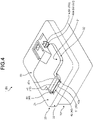
- the insertion opening 42b allows the second cover member 30 to open in a direction that intersects the plane direction of the contact plane between the work opening 21a and the closure section 31 of the second cover member 30 ( FIGS. 4 to 8 ).
- the insertion opening 42b allows the second cover member 30 to open in a direction that intersects the plane direction of the rectangular closure section 31 having the shape of a flat plate.
- This illustrative insertion opening 42b of the second cover member 30 opens outward in one of the directions perpendicular to the plane direction of the closure section 31 (the direction away from the interior space 12) when the second cover member 30 is in the closed position relative to the work opening 21a. Accordingly, when the second cover member 30 is in the closed position, the rotation shaft 41 retains the bearing 42, limiting detachment of the second cover member 30 from the first cover member 20.
- the through hole 43 is divided into two regions by the rotation shaft 41.
- One of the two regions of the through hole 43 separated by the rotation shaft 41 is used as an assembly work region for the coupling of the bearing 42 to the rotation shaft 41.
- the one used as the assembly work region is selected depending on in which of the directions perpendicular to the plane direction of the closure section 31 the insertion opening 42b opens.
- the region of the through hole 43 between the rotation shaft 41 and the work opening 21a is used as the assembly work region.
- the region of the through hole 43 that is located opposite to the work opening 21a with respect to the rotation shaft 41 is used as the assembly work region.
- the assembly work region of the through hole 43 is shaped and sized to allow the bearing 42 to be inserted from the free end and move in a direction that intersects the insertion direction and is perpendicular to the axial direction of the rotation shaft 41 to the shaft support position where the bearing 42 is fitted to the rotation shaft 41.
- the electric component housing (electrical connection box or conductive module) B and the cover structure 1 of the present embodiment include a detachment prevention structure 50, which disables detachment of the second cover member 30 from the first cover member 20 in an assembled state in which the first cover member 20 to which the second cover member 30 is coupled is coupled to the housing member 10 ( FIGS. 1 to 8 ).
- the detachment prevention structure 50 includes a rotational retaining section 51, which is formed in the bearing 42 to stop the rotation of the bearing 42 relative to the rotation shaft 41, and a retainer 52, which is formed in the housing member 10 to retain the bearing 42 while permitting the rotation of the bearing 42 relative to the rotation shaft 41 within the rotational range described above in the assembled state ( FIGS. 3 and 5 to 7 ).
- the rotational retaining section 51 protrudes from the outer circumferential surface of the bearing 42 ( FIGS. 3 to 8 ).
- the illustrated rotational retaining section 51 is formed on the outer circumferential surface of the free end of the bearing 42.
- the rotational retaining section 51 is provided as a protrusion on the outer circumferential surface of the other circumferential end of the bearing section 42a.
- the retainer 52 includes a first retaining section 52a, which is configured to retain the outer circumferential surface of the bearing 42 in the shaft support position regardless of the rotational position of the bearing 42 relative to the rotation shaft 41 within the rotational range described above ( FIGS. 3 , 6 , and 7 ).
- the first retaining section 52a is formed as an arcuate surface that faces the outer circumferential surface of the bearing section 42a in the assembled state and is coaxial with the bearing section 42a.
- This illustrative first retaining section 52a faces the outer circumferential surface of the bearing section 42a in the assembled state with a minute gap created in between.
- the bearing 42 is thus retained by the first retaining section 52a in the shaft support position regardless of the position of the second cover member 30 within the rotational range between the open position and the closed position. This limits detachment of the second cover member 30 from the first cover member 20.
- the retainer 52 includes a second retaining section 52b, which stops the rotational retaining section 51 when the second cover member 30 rotates from the closed position to the open position ( FIGS. 3 , 6 , and 7 ).
- the second retaining section 52b is a stopper wall surface that stops the rotational retaining section 51 so that the second cover member 30 in the open position does not rotate away from the closed position.
- the illustrative second retaining section 52b is formed as a flat surface continuous with the first retaining section 52a.
- the second retaining section 52b stops the rotational retaining section 51, preventing rotation beyond the open position. This limits detachment of the second cover member 30 from the first cover member 20.
- the electric component housing (electrical connection box or conductive module) B and the cover structure 1 further include a lock structure 60, which holds the second cover member 30 to the first cover member 20 in the closed position ( FIGS. 1 to 8 ).
- the lock structure 60 may include a first locking section 61 formed in the first cover member 20 and a second locking section 62 formed in the second cover member 30 ( FIGS. 1 to 7 ).
- the lock structure 60 locks the second cover member 30 from moving in the opening direction with the first and the second locking sections 61 and 62 in the closed position, thereby holding the second cover member 30 to the first cover member 20 ( FIGS. 4 to 6 ).
- a hook 61a of the first locking section 61 and a hook 62a of the second locking section 62 face each other in the closed position. The hooks 61a and 62a engage with each other when the second cover member 30 is about to move relative to the first cover member 20 in the opening direction, thereby holding the second cover member 30 to the first cover member 20.
- the rotation shaft 41 is first fitted to the inner circumference surface of the bearing 42 to assemble the first and the second cover members 20 and 30 together ( FIGS. 9 to 11 ).
- the first and the second cover members 20 and 30 are assembled, the first and the second locking sections 61 and 62 of the lock structure 60 are in engagement.
- the first cover member 20 to which the second cover member 30 is coupled is then coupled to the housing member 10 (from the state in FIGS. 10 and 11 to the state in FIGS. 4 to 6 ).
- the detachment prevention structure 50 is in a state where the detachment prevention structure 50 can exhibit its function, thereby limiting detachment of the second cover member 30 from the first cover member 20. That is, the electric component housing (electrical connection box or conductive module) B and the cover structure 1 are in a state where the first retaining section 52a retains the outer circumferential surface of the bearing 42 in the shaft support position, and the second retaining section 52b stops the rotational retaining section 51 when the second cover member 30 is rotated from the closed position to the open position.
- the electric component housing (electrical connection box or conductive module) B and the cover structure 1 for an electrical connection part of the present embodiment can limit detachment of the second cover member 30 from the first cover member 20 regardless of the rotational position of the second cover member 30 relative to the first cover member 20 in the rotational range described above.
- the bearing of the second cover member is retained by the first retaining section of the retainer in the shaft support position regardless of the position within the rotational range between the open position and the closed position.
- the electrical connection box and the cover structure for an electrical connection part thus limit detachment of the second cover member from the first cover member.
- the second retaining section of the retainer stops the rotational retaining section, preventing rotation beyond the open position.
- the electrical connection box and the cover structure for an electrical connection part thus limit detachment of the second cover member from the first cover member.
- the electrical connection box and the cover structure for an electrical connection part can limit detachment of the second cover member from the first cover member regardless of the rotational position of the second cover member relative to the first cover member.
Landscapes
- Engineering & Computer Science (AREA)
- Architecture (AREA)
- Civil Engineering (AREA)
- Structural Engineering (AREA)
- Mechanical Engineering (AREA)
- Connection Or Junction Boxes (AREA)
- Pivots And Pivotal Connections (AREA)
- Casings For Electric Apparatus (AREA)
Description
- The present invention relates to an electrical connection box and a cover structure for an electrical connection part.
- Vehicles such as automobiles are conventionally equipped with various electric connection objects and have housings enclosing electrical connection parts relating to these electric connection objects. Such a housing has a work opening that enables work relating to the electrical connection parts (e.g., attachment and detachment of the electric connection object) when required. The housing thus has a cover for closing the work opening. For example,
Japanese Patent Application Laid-open No. 2008-113534 - The cover may be molded integrally with the housing and other parts such as a living hinge. Alternatively, the cover may be molded as a part separate from the housing (a cover member) and then coupled to the housing by a hinge structure. In the latter case, the hinge structure is configured to allow the cover member to rotate between an open position and a closed position relative to the work opening. It is desirable that the hinge structure be configured so that the cover member is not detached from the housing in any position between the open position and the closed position. Further prior art is known from documents
US 5 979 016 A andGB 2 264 105 A - It is an objective of the present invention to provide an electrical connection box and a cover structure for an electrical connection part that are capable of limiting detachment of a cover member regardless of a rotational position of the cover member.
- In order to achieve the above mentioned object, an electrical connection box and a cover structure for an electrical connection part according to one aspect of the present invention includes a housing member having an opening and an interior space connecting to the opening, the interior space accommodating an electrical connection part; a first cover member including a closure section that closes the opening and has a work opening enabling work relating to the electrical connection part; a second cover member configured to close the work opening; a hinge structure configured to allow the second cover member to rotate within a rotational range between an open position and a closed position relative to the work opening; and a detachment prevention structure configured to disable detachment of the second cover member from the first cover member in an assembled state in which the first cover member to which the second cover member is coupled is coupled to the housing member, wherein the hinge structure includes a rotation shaft provided on the closure section, an arc-shaped cantilever bearing provided on the second cover member, the bearing having an inner circumference surface supporting the rotation shaft, and a through hole formed in the closure section, the through hole accommodating the rotation shaft and being configured to allow the bearing to be inserted from a free end side and move in a direction that intersects an insertion direction of the bearing and is perpendicular to an axial direction of the rotation shaft to a shaft support position where the bearing is fitted to the rotation shaft, the detachment prevention structure includes a rotational retaining section provided on the bearing and a retainer provided on the housing member, the rotational retaining section being configured to stop rotation of the bearing relative to the rotation shaft, the retainer being configured to retain the bearing while permitting rotation of the bearing relative to the rotation shaft within the rotational range in the assembled state, and the retainer includes a first retaining section and a second retaining section, the first retaining section being configured to retain an outer circumferential surface of the bearing in the shaft support position regardless of a rotational position of the bearing relative to the rotation shaft within the rotational range, the second retaining section being configured to stop the rotational retaining section when the second cover member rotates from the closed position to the open position.
- According to another aspect of the present invention, in the electrical connection box, it is preferable that the rotational retaining section is formed on the outer circumferential surface of the free end of the bearing.
- According to still another aspect of the present invention, in the electrical connection box, it is preferable that the bearing has an insertion opening inserting the rotation shaft to the shaft support position in a direction perpendicular to the axial direction, and the insertion opening opens in a direction intersecting a plane direction of a contact plane between the work opening and the second cover member.
- The above and other objects, features, advantages and technical and industrial significance of this invention will be better understood by reading the following detailed description of presently preferred embodiments of the invention, when considered in connection with the accompanying drawings.
-
-
FIG. 1 is a perspective view of a cover structure for an electrical connection part of an embodiment illustrated in an open position together with an electric component housing (electrical connection box), which is the application target of the cover structure; -
FIG. 2 is a top view of the cover structure for an electrical connection part of the embodiment illustrated in the open position together with the electric component housing (electrical connection box), which is the application target of the cover structure; -
FIG. 3 is a cross-sectional view taken along line X-X ofFIG. 2 ; -
FIG. 4 is a perspective view of the cover structure for an electrical connection part of the embodiment illustrated in a closed position together with the electric component housing (electrical connection box), which is the application target of the cover structure; -
FIG. 5 is a top view of the cover structure for an electrical connection part of the embodiment illustrated in the closed position together with the electric component housing (electrical connection box), which is the application target of the cover structure; -
FIG. 6 is a cross-sectional view taken along line X-X ofFIG. 5 ; -
FIG. 7 is an exploded perspective view of the cover structure for an electrical connection part and the electric component housing (electrical connection box); -
FIG. 8 is an exploded perspective view of the cover structure for an electrical connection part and the electric component housing (electrical connection box) as viewed from a different angle; -
FIG. 9 is a cross-sectional view taken along line X-X ofFIG. 7 , illustrating only the first and the second cover members; -
FIG. 10 is an exploded perspective view of the electric component housing (electrical connection box) after the first and the second cover members are assembled; and -
FIG. 11 is a cross-sectional view taken along line X-X ofFIG. 10 . - Referring to the drawings, embodiments of an electrical connection box and a cover structure for an electrical connection part according to the present invention are now described in detail. However, the present invention is not limited to these embodiments.
- Referring to
FIGS. 1 to 11 , one embodiment of an electrical connection box and a cover structure for an electrical connection part according to the present invention is now described. - A
cover structure 1 is applied to an electric component housing B for accommodating an electric component (FIGS. 1 to 8 ). For example, the electric component housing B may be an electrical connection box or a conductive module, such as a bus bar module. - In an electrical connection box, for example, an insulative housing encloses an electronic component serving as an electric connection object, to which another electric connection object, which may be a conductive member (e.g., a conductive bus bar) or an electric wire, is electrically connected within the housing. With this electrical connection box, an electrical connection part may be a physical and electrical connection part between the electronic component and the conductive member, a physical and electrical connection part between the electronic component and the electric wire, a physical and electrical connection part between the conductive member and the electric wire, or a physical and electrical connection part between the electric wires through terminal fittings. The electronic component may be a circuit protection component, such as a relay or a fuse. The electronic component may be an electronic device, such as a circuit board or an electronic control unit (ECU). For example, a plurality of electric wires extends from the electrical connection box, and electric connection objects such as devices and power supplies in the vehicle are electrically connected via the wires. The electrical connection box forms a wire harness with such wires.
- With this electrical connection box, some work may be required for the electrical connection parts within the housing. Examples of the work relating to the electrical connection parts include attachment and detachment of the electronic component to and from the conductive member (insertion and extraction), attachment and detachment of the terminal fitting at an end of the electric wire to and from the electronic component or the conductive member (e.g., fastening by screws), attachment and detachment between terminal fittings (e.g., fastening by screws), attachment and detachment of a connector to and from the electronic component (insertion and extraction), and inspection of the circuit protection component. To this end, the housing has a work opening that enables work relating to the electrical connection parts. The work opening is covered with a cover member, which can be opened and closed.
- For example, the conductive module may be used in a vehicle, such as an electric vehicle or a hybrid vehicle, to electrically connect adjacent battery cells forming a battery module, or to electrically connect battery cells to a battery monitoring unit. In this conductive module, a plurality of housing chambers may be formed in an insulative housing, and conductive members (e.g., conductive bus bars) may be accommodated in the respective housing chambers. The conductive members may physically and electrically connect the electrode terminals of the adjacent battery cells to each other. Furthermore, one end of an electric wire is physically and electrically connected to the conductive member in each housing chamber. The other end of the wire is physically and electrically connected to the battery monitoring unit. With this conductive module, an electrical connection part may be a physical and electrical connection part between the conductive member and the electrode terminal, a physical and electrical connection part between the conductive member and the electric wire, or a physical and electrical connection part between the electric wire and the battery monitoring unit.
- In this conductive module, when attachment and detachment are performed on the battery module, certain work is performed on the electrical connection parts in the housing. Examples of work relating to the electrical connection parts include attachment and detachment of the conductive member to and from the electrode terminal (e.g., fastening by screws or welding) and attachment and detachment of the electric wire to and from the conductive member (e.g., connector insertion and extraction or welding). To this end, the housing has a work opening (an opening of each housing chamber) that enables work relating to the electrical connection parts. The work opening is covered with a cover member, which can be opened and closed.
- Specifically, the electric component housing (electrical connection box or conductive module) B and the
cover structure 1 of the present embodiment include ahousing member 10 and afirst cover member 20, which form a housing, and asecond cover member 30, which closes the work opening of the housing (FIGS. 1 to 8 ). Thehousing member 10 and thefirst cover members 20 and thesecond cover member 30 are individually molded using an insulating material such as synthetic resin. - The
housing member 10 has an opening 11 and aninterior space 12 connecting to the opening 11 (FIGS. 3 and6 to 8 ). Theinterior space 12 of thehousing member 10 accommodates electrical connection parts (not illustrated). Thehousing member 10 detailed here has the shape of a rectangular box with onerectangular opening 11. - The
first cover member 20 has aclosure section 21, which closes the opening 11 of thehousing member 10, and a tubularperipheral wall 22 projecting from the periphery of the closure section 21 (FIGS. 1 to 8 ). Theclosure section 21 closes theopening 11, and the inner circumference surface of theperipheral wall 22 covers the outer circumferential surface of the end at theopening 11 of thehousing member 10. Thefirst cover member 20 thus forms a box together with thehousing member 10. Thefirst cover member 20 detailed here has therectangular closure section 21 having the shape of a flat plate and theperipheral wall 22 having the shape of a rectangular tube. - The
closure section 21 of thefirst cover member 20 has awork opening 21a, which enables work relating to the electrical connection parts, and aperipheral wall section 21b, which projects outward (the outside of the assembledhousing member 10 and the first cover member 20) from the rim of thework opening 21a (FIGS. 1 to 3 and6 to 8 ). When the assembledhousing member 10 and thefirst cover member 20 are viewed from the outside, theinterior space 12 is located on the inner side of thework opening 21a, and the electrical connection parts are located on the inner side of thework opening 21a. Theclosure section 21 detailed here includes therectangular work opening 21a and theperipheral wall section 21b, which has the shape of a rectangular tube. - The
second cover member 30 has aclosure section 31, which closes thework opening 21a in theclosure section 21 of thefirst cover member 20, and a tubularperipheral wall 32 projecting from the periphery of the closure section 31 (FIGS. 1 to 8 ). Thesecond cover member 30 closes thework opening 21a with itsclosure section 31, and covers the outer circumferential surface of theperipheral wall section 21b of theclosure section 21 of thefirst cover member 20 with the inner circumference surface of theperipheral wall 32 of thesecond cover member 30. Thesecond cover member 30 detailed here has therectangular closure section 31 having the shape of a flat plate and theperipheral wall 32 having the shape of a rectangular tube. - Furthermore, the electric component housing (electrical connection box or conductive module) B and the
cover structure 1 of the present embodiment include ahinge structure 40, which allows thesecond cover member 30 to rotate in a rotational range between an open position and a closed position relative to thework opening 21a (FIGS. 1 to 8 ). Thesecond cover member 30 closes thework opening 21a in the closed position and opens thework opening 21a in the open position. - The
hinge structure 40 includes arotation shaft 41, which is formed in theclosure section 21 of thefirst cover member 20, and an arc-shaped cantilever bearing 42, which is formed in thesecond cover member 30 and has an inner circumference surface supporting the rotation shaft 41 (FIGS. 3 to 8 ). Thehinge structure 40 also includes a throughhole 43 formed in theclosure section 21 of the first cover member 20 (FIGS. 3 to 8 ). The throughhole 43 is a hole formed in theclosure section 21 of thefirst cover member 20 to accommodate therotation shaft 41 and is also used when thebearing 42 is coupled to therotation shaft 41. - The
rotation shaft 41 is cylindrical and positioned next to and spaced apart from thework opening 21a. Therotation shaft 41 is positioned next to the work opening 21a together with the throughhole 43 and accommodated in the throughhole 43. Thisillustrative rotation shaft 41 is positioned next to and spaced apart from one side of the rim of therectangular work opening 21a, and is arranged so that the direction in which the one side extends and the axial direction of therotation shaft 41 are parallel. - At least one
bearing 42 is provided in a cantilever manner with respect to theclosure section 31 of thesecond cover member 30. Thebearing 42 has abearing section 42a formed as a curved part, which has an arcuate cross-sectional shape in a plane perpendicular to the axial direction (FIGS. 3 to 8 ). Thebearing section 42a has a circumferential end connected to the fixed end of thebearing 42, and another circumferential end serving as the free end of thebearing 42. Thebearing section 42a is semicircular or has the shape of a major arc. Thebearing section 42a detailed here has a semicircular cross-sectional shape in a plane perpendicular to the axial direction, that is, has a semi-cylindrical shape. - The
bearing section 42a has an arcuate inner circumference surface and an arcuate outer circumferential surface, and supports therotation shaft 41 on its inner circumference surface. Thebearing 42 has aninsertion opening 42b for inserting therotation shaft 41 to a shaft support position in a direction perpendicular to the axial direction (FIGS. 3 to 8 ). With thisbearing 42, the opening of the arcuate shape of thebearing section 42a, which is a curved part, serves as theinsertion opening 42b. Furthermore, if thebearing 42 has a projection extending tangentially from the other circumferential end of thebearing section 42a, this projection has the free end. As such, the opening at the free end of the projection serves as theinsertion opening 42b. In either case, theinsertion opening 42b allows thesecond cover member 30 to open in a direction that intersects the plane direction of the contact plane between thework opening 21a and theclosure section 31 of the second cover member 30 (FIGS. 4 to 8 ). In other words, in this illustrative embodiment, theinsertion opening 42b allows thesecond cover member 30 to open in a direction that intersects the plane direction of therectangular closure section 31 having the shape of a flat plate. Thisillustrative insertion opening 42b of thesecond cover member 30 opens outward in one of the directions perpendicular to the plane direction of the closure section 31 (the direction away from the interior space 12) when thesecond cover member 30 is in the closed position relative to thework opening 21a. Accordingly, when thesecond cover member 30 is in the closed position, therotation shaft 41 retains thebearing 42, limiting detachment of thesecond cover member 30 from thefirst cover member 20. - The through
hole 43 is divided into two regions by therotation shaft 41. One of the two regions of the throughhole 43 separated by therotation shaft 41 is used as an assembly work region for the coupling of thebearing 42 to therotation shaft 41. With this throughhole 43, of the two regions separated by therotation shaft 41, the one used as the assembly work region is selected depending on in which of the directions perpendicular to the plane direction of theclosure section 31 theinsertion opening 42b opens. In this example, the region of the throughhole 43 between therotation shaft 41 and thework opening 21a is used as the assembly work region. If theinsertion opening 42b opens inward in one of the directions perpendicular to the plane direction of the closure section 31 (the direction toward the interior space 12) when thesecond cover member 30 is in the closed position relative to thework opening 21a, the region of the throughhole 43 that is located opposite to thework opening 21a with respect to therotation shaft 41 is used as the assembly work region. In either case, the assembly work region of the throughhole 43 is shaped and sized to allow thebearing 42 to be inserted from the free end and move in a direction that intersects the insertion direction and is perpendicular to the axial direction of therotation shaft 41 to the shaft support position where thebearing 42 is fitted to therotation shaft 41. - Furthermore, the electric component housing (electrical connection box or conductive module) B and the
cover structure 1 of the present embodiment include adetachment prevention structure 50, which disables detachment of thesecond cover member 30 from thefirst cover member 20 in an assembled state in which thefirst cover member 20 to which thesecond cover member 30 is coupled is coupled to the housing member 10 (FIGS. 1 to 8 ). Thedetachment prevention structure 50 includes arotational retaining section 51, which is formed in thebearing 42 to stop the rotation of thebearing 42 relative to therotation shaft 41, and aretainer 52, which is formed in thehousing member 10 to retain thebearing 42 while permitting the rotation of thebearing 42 relative to therotation shaft 41 within the rotational range described above in the assembled state (FIGS. 3 and5 to 7 ). - The
rotational retaining section 51 protrudes from the outer circumferential surface of the bearing 42 (FIGS. 3 to 8 ). The illustratedrotational retaining section 51 is formed on the outer circumferential surface of the free end of thebearing 42. In this example, therotational retaining section 51 is provided as a protrusion on the outer circumferential surface of the other circumferential end of thebearing section 42a. - The
retainer 52 includes afirst retaining section 52a, which is configured to retain the outer circumferential surface of the bearing 42 in the shaft support position regardless of the rotational position of thebearing 42 relative to therotation shaft 41 within the rotational range described above (FIGS. 3 ,6 , and7 ). Thefirst retaining section 52a is formed as an arcuate surface that faces the outer circumferential surface of thebearing section 42a in the assembled state and is coaxial with thebearing section 42a. This illustrativefirst retaining section 52a faces the outer circumferential surface of thebearing section 42a in the assembled state with a minute gap created in between. Thebearing 42 is thus retained by thefirst retaining section 52a in the shaft support position regardless of the position of thesecond cover member 30 within the rotational range between the open position and the closed position. This limits detachment of thesecond cover member 30 from thefirst cover member 20. - If the
bearing 42 does not include therotational retaining section 51, thesecond cover member 30 can move rotationally beyond the open position when moving from the closed position to the open position. The free end of the bearing 42 of such asecond cover member 30 can therefore move out of the throughhole 43. That is, thesecond cover member 30 can be detached from thefirst cover member 20. For this reason, theretainer 52 includes asecond retaining section 52b, which stops therotational retaining section 51 when thesecond cover member 30 rotates from the closed position to the open position (FIGS. 3 ,6 , and7 ). Thesecond retaining section 52b is a stopper wall surface that stops therotational retaining section 51 so that thesecond cover member 30 in the open position does not rotate away from the closed position. The illustrativesecond retaining section 52b is formed as a flat surface continuous with thefirst retaining section 52a. When thesecond cover member 30 rotates from the closed position to the open position, thesecond retaining section 52b stops therotational retaining section 51, preventing rotation beyond the open position. This limits detachment of thesecond cover member 30 from thefirst cover member 20. - The electric component housing (electrical connection box or conductive module) B and the
cover structure 1 further include alock structure 60, which holds thesecond cover member 30 to thefirst cover member 20 in the closed position (FIGS. 1 to 8 ). Thelock structure 60 may include afirst locking section 61 formed in thefirst cover member 20 and asecond locking section 62 formed in the second cover member 30 (FIGS. 1 to 7 ). Thelock structure 60 locks thesecond cover member 30 from moving in the opening direction with the first and thesecond locking sections second cover member 30 to the first cover member 20 (FIGS. 4 to 6 ). Ahook 61a of thefirst locking section 61 and ahook 62a of thesecond locking section 62 face each other in the closed position. Thehooks second cover member 30 is about to move relative to thefirst cover member 20 in the opening direction, thereby holding thesecond cover member 30 to thefirst cover member 20. - With the electric component housing (electrical connection box or conductive module) B and the
cover structure 1 for an electrical connection part of the present embodiment, therotation shaft 41 is first fitted to the inner circumference surface of thebearing 42 to assemble the first and thesecond cover members FIGS. 9 to 11 ). In this example, when the first and thesecond cover members second locking sections lock structure 60 are in engagement. With the electric component housing (electrical connection box or conductive module) B and thecover structure 1, thefirst cover member 20 to which thesecond cover member 30 is coupled is then coupled to the housing member 10 (from the state inFIGS. 10 and11 to the state inFIGS. 4 to 6 ). As a result, in the electric component housing (electrical connection box or conductive module) B and thecover structure 1, thedetachment prevention structure 50 is in a state where thedetachment prevention structure 50 can exhibit its function, thereby limiting detachment of thesecond cover member 30 from thefirst cover member 20. That is, the electric component housing (electrical connection box or conductive module) B and thecover structure 1 are in a state where thefirst retaining section 52a retains the outer circumferential surface of the bearing 42 in the shaft support position, and thesecond retaining section 52b stops therotational retaining section 51 when thesecond cover member 30 is rotated from the closed position to the open position. - As described above, the electric component housing (electrical connection box or conductive module) B and the
cover structure 1 for an electrical connection part of the present embodiment can limit detachment of thesecond cover member 30 from thefirst cover member 20 regardless of the rotational position of thesecond cover member 30 relative to thefirst cover member 20 in the rotational range described above. - In the electrical connection box and the cover structure for an electrical connection part of the present embodiment, the bearing of the second cover member is retained by the first retaining section of the retainer in the shaft support position regardless of the position within the rotational range between the open position and the closed position. The electrical connection box and the cover structure for an electrical connection part thus limit detachment of the second cover member from the first cover member. Additionally, with the electrical connection box and the cover structure for an electrical connection part, when the second cover member rotates from the closed position to the open position, the second retaining section of the retainer stops the rotational retaining section, preventing rotation beyond the open position. The electrical connection box and the cover structure for an electrical connection part thus limit detachment of the second cover member from the first cover member. As described above, the electrical connection box and the cover structure for an electrical connection part according to the present embodiment can limit detachment of the second cover member from the first cover member regardless of the rotational position of the second cover member relative to the first cover member.
Claims (4)
- An electrical connection box (B) comprising:a housing member (10) having an opening (11) and an interior space (12) connecting to the opening (11), the interior space (12) accommodating an electrical connection part;a first cover member (20) including a closure section (21) that closes the opening (11) and has a work opening (21a) enabling work relating to the electrical connection part;a second cover member (30) configured to close the work opening (21a) ;a hinge structure (40) configured to allow the second cover member (30) to rotate within a rotational range between an open position and a closed position relative to the work opening (21a); anda detachment prevention structure (50) configured to disable detachment of the second cover member (30) from the first cover member (20) in an assembled state in which the first cover member (20) to which the second cover member (30) is coupled is coupled to the housing member (10), whereinthe hinge structure (40) includes a rotation shaft (41) provided on the closure section (21), an arc-shaped cantilever bearing (42) provided on the second cover member (30), the bearing (42) having an inner circumference surface supporting the rotation shaft (41), and a through hole (43) formed in the closure section (21), the through hole (43) accommodating the rotation shaft (41) and being configured to allow the bearing (42) to be inserted from a free end side and move in a direction that intersects an insertion direction of the bearing (42) and is perpendicular to an axial direction of the rotation shaft (41) to a shaft support position where the bearing (42) is fitted to the rotation shaft (41),the detachment prevention structure (50) includes a rotational retaining section (51) provided on the bearing (42) and a retainer (52) provided on the housing member (10), the rotational retaining section (51) being configured to stop rotation of the bearing (42) relative to the rotation shaft (41), the retainer (52) being configured to retain the bearing (42) while permitting rotation of the bearing (42) relative to the rotation shaft (41) within the rotational range in the assembled state, andthe retainer (52) includes a first retaining section (52a) and a second retaining section (52b), the first retaining section (52a) being configured to retain an outer circumferential surface of the bearing (42) in the shaft support position regardless of a rotational position of the bearing (42) relative to the rotation shaft (41) within the rotational range, the second retaining section (52b) being configured to stop the rotational retaining section (51) when the second cover member (30) rotates from the closed position to the open position.
- The electrical connection box (B) according to claim 1,
wherein
the rotational retaining section (51) is formed on the outer circumferential surface of the free end of the bearing (42). - The electrical connection box (B) according to claim 1 or 2, whereinthe bearing (42) has an insertion opening (42b) inserting the rotation shaft (41) to the shaft support position in a direction perpendicular to the axial direction, andthe insertion opening (42b) opens in a direction intersecting a plane direction of a contact plane between the work opening (21a) and the second cover member (30).
- A cover structure (1) for an electrical connection part comprising:
the electrical connection box (B) according to claim 1.
Applications Claiming Priority (1)
| Application Number | Priority Date | Filing Date | Title |
|---|---|---|---|
| JP2020005018A JP7051252B2 (en) | 2020-01-16 | 2020-01-16 | Cover structure of electrical junction box and electrical connection points |
Publications (2)
| Publication Number | Publication Date |
|---|---|
| EP3851334A1 EP3851334A1 (en) | 2021-07-21 |
| EP3851334B1 true EP3851334B1 (en) | 2022-04-20 |
Family
ID=74184405
Family Applications (1)
| Application Number | Title | Priority Date | Filing Date |
|---|---|---|---|
| EP21151335.3A Active EP3851334B1 (en) | 2020-01-16 | 2021-01-13 | Electrical connection box and cover structure for electrical connection part |
Country Status (4)
| Country | Link |
|---|---|
| US (1) | US11431159B2 (en) |
| EP (1) | EP3851334B1 (en) |
| JP (1) | JP7051252B2 (en) |
| CN (1) | CN113140992B (en) |
Families Citing this family (4)
| Publication number | Priority date | Publication date | Assignee | Title |
|---|---|---|---|---|
| AU2016410602B2 (en) * | 2016-06-23 | 2022-07-28 | Landis+Gyr Technology, Inc. | Utility meter enclosure with dual position locks |
| JP7406531B2 (en) * | 2021-11-11 | 2023-12-27 | 住友電装株式会社 | electrical junction box |
| JP7513664B2 (en) * | 2022-07-11 | 2024-07-09 | 矢崎総業株式会社 | Electrical connection box and manufacturing method |
| JP7513663B2 (en) * | 2022-07-11 | 2024-07-09 | 矢崎総業株式会社 | Electrical Junction Box |
Family Cites Families (21)
| Publication number | Priority date | Publication date | Assignee | Title |
|---|---|---|---|---|
| NL301890A (en) * | 1962-12-21 | |||
| JPH083142Y2 (en) * | 1990-02-19 | 1996-01-29 | 矢崎総業株式会社 | Electrical junction box hinge structure |
| US5076455A (en) * | 1991-04-15 | 1991-12-31 | Coopoer Industries, Inc. | Integral hinge for electrical equipment enclosures |
| US5146650A (en) * | 1991-05-31 | 1992-09-15 | Amp Incorporated | Molded latchable hinge |
| JPH0575276A (en) * | 1991-09-11 | 1993-03-26 | Fujitsu Ltd | Rotating structure of cover |
| DE4303784A1 (en) * | 1992-02-12 | 1993-08-19 | Fluoroware Inc | |
| US5317108A (en) * | 1992-12-15 | 1994-05-31 | L.E. Mason Company | Weather-resistant electrical outlet cover assembly |
| US5979016A (en) * | 1998-08-12 | 1999-11-09 | Mustek Systems Inc. | Cover hinge structure |
| US6145165A (en) * | 1998-10-13 | 2000-11-14 | Alwind Industries, Ltd. | Hinge mechanism |
| US6133531A (en) * | 1998-11-03 | 2000-10-17 | Pass & Seymour, Inc. | Weatherproof outlet cover |
| JP4113756B2 (en) | 2002-10-11 | 2008-07-09 | 矢崎総業株式会社 | Power supply box |
| US7041897B2 (en) * | 2004-02-10 | 2006-05-09 | Adc Telecommunications, Inc. | Hinge for cable trough cover |
| US8024839B2 (en) * | 2006-03-26 | 2011-09-27 | Chatsworth Products, Inc. | Indexing hinge |
| US7626121B1 (en) | 2006-10-06 | 2009-12-01 | Taymac Corporation | Electrical outlet cover with tightening hinge |
| JP4605143B2 (en) | 2006-10-31 | 2011-01-05 | 住友電装株式会社 | In-vehicle electrical junction box |
| US8944266B2 (en) * | 2008-09-23 | 2015-02-03 | Dirtt Environmental Solutions Ltd. | Floor-mount service container and lid |
| US8633385B2 (en) * | 2010-11-09 | 2014-01-21 | Hubbell Incorporated | Weatherproof cover having bidirectional hinge |
| US8695166B2 (en) * | 2012-08-01 | 2014-04-15 | Shin Zu Shing Co., Ltd | Hinge for a portable computing device |
| US9203222B2 (en) * | 2013-03-12 | 2015-12-01 | Hubbell Incorporated | While in use weatherproof cover for an electrical box |
| US9035182B2 (en) * | 2013-03-15 | 2015-05-19 | Hubbell Incorporated | Floor box cover assembly |
| US10931053B2 (en) * | 2018-04-11 | 2021-02-23 | Hubbell Incorporated | Expandable electrical device cover |
-
2020
- 2020-01-16 JP JP2020005018A patent/JP7051252B2/en active Active
-
2021
- 2021-01-11 US US17/146,451 patent/US11431159B2/en active Active
- 2021-01-13 EP EP21151335.3A patent/EP3851334B1/en active Active
- 2021-01-14 CN CN202110047181.3A patent/CN113140992B/en active Active
Also Published As
| Publication number | Publication date |
|---|---|
| US20210226431A1 (en) | 2021-07-22 |
| JP7051252B2 (en) | 2022-04-11 |
| US11431159B2 (en) | 2022-08-30 |
| JP2021114803A (en) | 2021-08-05 |
| EP3851334A1 (en) | 2021-07-21 |
| CN113140992B (en) | 2022-11-29 |
| CN113140992A (en) | 2021-07-20 |
Similar Documents
| Publication | Publication Date | Title |
|---|---|---|
| EP3851334B1 (en) | Electrical connection box and cover structure for electrical connection part | |
| US5246377A (en) | Apparatus for electrically connecting a rotary connector and a wiring harness | |
| CN103682882B (en) | Connector connection structure | |
| JP5973881B2 (en) | Connector connection structure | |
| US20160315459A1 (en) | Electrical connection box and wire harness | |
| JP6537483B2 (en) | Power connection system | |
| EP3671974B1 (en) | Connector | |
| CN111313341B (en) | Cover structure of electric connection part | |
| CN111200206B (en) | Cover structure of electrical connection part | |
| CN118044081A (en) | Wire harness and protector | |
| JP7838946B2 (en) | terminal block | |
| US12003064B2 (en) | Electronic part with integrated fuse | |
| US12424780B2 (en) | Power harness | |
| JP7723132B2 (en) | Connector assembly for battery modules in electric vehicles | |
| JP7772573B2 (en) | Connectors and resin exterior components | |
| US20230387622A1 (en) | Electrical safety connector | |
| US20250273878A1 (en) | Connector | |
| JP7753948B2 (en) | Charging connector | |
| CN114824872B (en) | Wire harness plug and assembly | |
| JP7732867B2 (en) | Electrical connectors and electrical junction boxes | |
| JP7677204B2 (en) | Charging connector | |
| JP2025129563A (en) | connector | |
| JP2023057194A (en) | battery terminal cover | |
| JP2025163752A (en) | Cover Structure | |
| JPH08195239A (en) | Electric vehicle connector |
Legal Events
| Date | Code | Title | Description |
|---|---|---|---|
| PUAI | Public reference made under article 153(3) epc to a published international application that has entered the european phase |
Free format text: ORIGINAL CODE: 0009012 |
|
| STAA | Information on the status of an ep patent application or granted ep patent |
Free format text: STATUS: REQUEST FOR EXAMINATION WAS MADE |
|
| 17P | Request for examination filed |
Effective date: 20210113 |
|
| AK | Designated contracting states |
Kind code of ref document: A1 Designated state(s): AL AT BE BG CH CY CZ DE DK EE ES FI FR GB GR HR HU IE IS IT LI LT LU LV MC MK MT NL NO PL PT RO RS SE SI SK SM TR |
|
| RIC1 | Information provided on ipc code assigned before grant |
Ipc: H05K 5/03 20060101ALN20211021BHEP Ipc: E05D 7/10 20060101ALI20211021BHEP Ipc: E05D 3/04 20060101ALI20211021BHEP Ipc: H05K 5/02 20060101ALI20211021BHEP Ipc: H02G 3/14 20060101ALI20211021BHEP Ipc: B60R 16/023 20060101AFI20211021BHEP |
|
| GRAP | Despatch of communication of intention to grant a patent |
Free format text: ORIGINAL CODE: EPIDOSNIGR1 |
|
| STAA | Information on the status of an ep patent application or granted ep patent |
Free format text: STATUS: GRANT OF PATENT IS INTENDED |
|
| RIC1 | Information provided on ipc code assigned before grant |
Ipc: H05K 5/03 20060101ALN20211115BHEP Ipc: E05D 7/10 20060101ALI20211115BHEP Ipc: E05D 3/04 20060101ALI20211115BHEP Ipc: H05K 5/02 20060101ALI20211115BHEP Ipc: H02G 3/14 20060101ALI20211115BHEP Ipc: B60R 16/023 20060101AFI20211115BHEP |
|
| INTG | Intention to grant announced |
Effective date: 20211222 |
|
| GRAS | Grant fee paid |
Free format text: ORIGINAL CODE: EPIDOSNIGR3 |
|
| GRAA | (expected) grant |
Free format text: ORIGINAL CODE: 0009210 |
|
| STAA | Information on the status of an ep patent application or granted ep patent |
Free format text: STATUS: THE PATENT HAS BEEN GRANTED |
|
| AK | Designated contracting states |
Kind code of ref document: B1 Designated state(s): AL AT BE BG CH CY CZ DE DK EE ES FI FR GB GR HR HU IE IS IT LI LT LU LV MC MK MT NL NO PL PT RO RS SE SI SK SM TR |
|
| REG | Reference to a national code |
Ref country code: GB Ref legal event code: FG4D |
|
| REG | Reference to a national code |
Ref country code: CH Ref legal event code: EP |
|
| REG | Reference to a national code |
Ref country code: DE Ref legal event code: R096 Ref document number: 602021000054 Country of ref document: DE |
|
| REG | Reference to a national code |
Ref country code: IE Ref legal event code: FG4D |
|
| REG | Reference to a national code |
Ref country code: AT Ref legal event code: REF Ref document number: 1484938 Country of ref document: AT Kind code of ref document: T Effective date: 20220515 |
|
| REG | Reference to a national code |
Ref country code: LT Ref legal event code: MG9D |
|
| REG | Reference to a national code |
Ref country code: NL Ref legal event code: MP Effective date: 20220420 |
|
| REG | Reference to a national code |
Ref country code: AT Ref legal event code: MK05 Ref document number: 1484938 Country of ref document: AT Kind code of ref document: T Effective date: 20220420 |
|
| PG25 | Lapsed in a contracting state [announced via postgrant information from national office to epo] |
Ref country code: NL Free format text: LAPSE BECAUSE OF FAILURE TO SUBMIT A TRANSLATION OF THE DESCRIPTION OR TO PAY THE FEE WITHIN THE PRESCRIBED TIME-LIMIT Effective date: 20220420 |
|
| PG25 | Lapsed in a contracting state [announced via postgrant information from national office to epo] |
Ref country code: SE Free format text: LAPSE BECAUSE OF FAILURE TO SUBMIT A TRANSLATION OF THE DESCRIPTION OR TO PAY THE FEE WITHIN THE PRESCRIBED TIME-LIMIT Effective date: 20220420 Ref country code: PT Free format text: LAPSE BECAUSE OF FAILURE TO SUBMIT A TRANSLATION OF THE DESCRIPTION OR TO PAY THE FEE WITHIN THE PRESCRIBED TIME-LIMIT Effective date: 20220822 Ref country code: NO Free format text: LAPSE BECAUSE OF FAILURE TO SUBMIT A TRANSLATION OF THE DESCRIPTION OR TO PAY THE FEE WITHIN THE PRESCRIBED TIME-LIMIT Effective date: 20220720 Ref country code: LT Free format text: LAPSE BECAUSE OF FAILURE TO SUBMIT A TRANSLATION OF THE DESCRIPTION OR TO PAY THE FEE WITHIN THE PRESCRIBED TIME-LIMIT Effective date: 20220420 Ref country code: HR Free format text: LAPSE BECAUSE OF FAILURE TO SUBMIT A TRANSLATION OF THE DESCRIPTION OR TO PAY THE FEE WITHIN THE PRESCRIBED TIME-LIMIT Effective date: 20220420 Ref country code: GR Free format text: LAPSE BECAUSE OF FAILURE TO SUBMIT A TRANSLATION OF THE DESCRIPTION OR TO PAY THE FEE WITHIN THE PRESCRIBED TIME-LIMIT Effective date: 20220721 Ref country code: FI Free format text: LAPSE BECAUSE OF FAILURE TO SUBMIT A TRANSLATION OF THE DESCRIPTION OR TO PAY THE FEE WITHIN THE PRESCRIBED TIME-LIMIT Effective date: 20220420 Ref country code: ES Free format text: LAPSE BECAUSE OF FAILURE TO SUBMIT A TRANSLATION OF THE DESCRIPTION OR TO PAY THE FEE WITHIN THE PRESCRIBED TIME-LIMIT Effective date: 20220420 Ref country code: BG Free format text: LAPSE BECAUSE OF FAILURE TO SUBMIT A TRANSLATION OF THE DESCRIPTION OR TO PAY THE FEE WITHIN THE PRESCRIBED TIME-LIMIT Effective date: 20220720 Ref country code: AT Free format text: LAPSE BECAUSE OF FAILURE TO SUBMIT A TRANSLATION OF THE DESCRIPTION OR TO PAY THE FEE WITHIN THE PRESCRIBED TIME-LIMIT Effective date: 20220420 |
|
| PG25 | Lapsed in a contracting state [announced via postgrant information from national office to epo] |
Ref country code: RS Free format text: LAPSE BECAUSE OF FAILURE TO SUBMIT A TRANSLATION OF THE DESCRIPTION OR TO PAY THE FEE WITHIN THE PRESCRIBED TIME-LIMIT Effective date: 20220420 Ref country code: PL Free format text: LAPSE BECAUSE OF FAILURE TO SUBMIT A TRANSLATION OF THE DESCRIPTION OR TO PAY THE FEE WITHIN THE PRESCRIBED TIME-LIMIT Effective date: 20220420 Ref country code: LV Free format text: LAPSE BECAUSE OF FAILURE TO SUBMIT A TRANSLATION OF THE DESCRIPTION OR TO PAY THE FEE WITHIN THE PRESCRIBED TIME-LIMIT Effective date: 20220420 Ref country code: IS Free format text: LAPSE BECAUSE OF FAILURE TO SUBMIT A TRANSLATION OF THE DESCRIPTION OR TO PAY THE FEE WITHIN THE PRESCRIBED TIME-LIMIT Effective date: 20220820 |
|
| REG | Reference to a national code |
Ref country code: DE Ref legal event code: R097 Ref document number: 602021000054 Country of ref document: DE |
|
| PG25 | Lapsed in a contracting state [announced via postgrant information from national office to epo] |
Ref country code: SM Free format text: LAPSE BECAUSE OF FAILURE TO SUBMIT A TRANSLATION OF THE DESCRIPTION OR TO PAY THE FEE WITHIN THE PRESCRIBED TIME-LIMIT Effective date: 20220420 Ref country code: SK Free format text: LAPSE BECAUSE OF FAILURE TO SUBMIT A TRANSLATION OF THE DESCRIPTION OR TO PAY THE FEE WITHIN THE PRESCRIBED TIME-LIMIT Effective date: 20220420 Ref country code: RO Free format text: LAPSE BECAUSE OF FAILURE TO SUBMIT A TRANSLATION OF THE DESCRIPTION OR TO PAY THE FEE WITHIN THE PRESCRIBED TIME-LIMIT Effective date: 20220420 Ref country code: EE Free format text: LAPSE BECAUSE OF FAILURE TO SUBMIT A TRANSLATION OF THE DESCRIPTION OR TO PAY THE FEE WITHIN THE PRESCRIBED TIME-LIMIT Effective date: 20220420 Ref country code: DK Free format text: LAPSE BECAUSE OF FAILURE TO SUBMIT A TRANSLATION OF THE DESCRIPTION OR TO PAY THE FEE WITHIN THE PRESCRIBED TIME-LIMIT Effective date: 20220420 Ref country code: CZ Free format text: LAPSE BECAUSE OF FAILURE TO SUBMIT A TRANSLATION OF THE DESCRIPTION OR TO PAY THE FEE WITHIN THE PRESCRIBED TIME-LIMIT Effective date: 20220420 |
|
| PLBE | No opposition filed within time limit |
Free format text: ORIGINAL CODE: 0009261 |
|
| STAA | Information on the status of an ep patent application or granted ep patent |
Free format text: STATUS: NO OPPOSITION FILED WITHIN TIME LIMIT |
|
| 26N | No opposition filed |
Effective date: 20230123 |
|
| PG25 | Lapsed in a contracting state [announced via postgrant information from national office to epo] |
Ref country code: AL Free format text: LAPSE BECAUSE OF FAILURE TO SUBMIT A TRANSLATION OF THE DESCRIPTION OR TO PAY THE FEE WITHIN THE PRESCRIBED TIME-LIMIT Effective date: 20220420 |
|
| PG25 | Lapsed in a contracting state [announced via postgrant information from national office to epo] |
Ref country code: SI Free format text: LAPSE BECAUSE OF FAILURE TO SUBMIT A TRANSLATION OF THE DESCRIPTION OR TO PAY THE FEE WITHIN THE PRESCRIBED TIME-LIMIT Effective date: 20220420 |
|
| PGFP | Annual fee paid to national office [announced via postgrant information from national office to epo] |
Ref country code: DE Payment date: 20221130 Year of fee payment: 3 |
|
| PG25 | Lapsed in a contracting state [announced via postgrant information from national office to epo] |
Ref country code: LU Free format text: LAPSE BECAUSE OF NON-PAYMENT OF DUE FEES Effective date: 20230113 |
|
| REG | Reference to a national code |
Ref country code: BE Ref legal event code: MM Effective date: 20230131 |
|
| PG25 | Lapsed in a contracting state [announced via postgrant information from national office to epo] |
Ref country code: FR Free format text: LAPSE BECAUSE OF NON-PAYMENT OF DUE FEES Effective date: 20230131 Ref country code: BE Free format text: LAPSE BECAUSE OF NON-PAYMENT OF DUE FEES Effective date: 20230131 |
|
| PG25 | Lapsed in a contracting state [announced via postgrant information from national office to epo] |
Ref country code: IT Free format text: LAPSE BECAUSE OF FAILURE TO SUBMIT A TRANSLATION OF THE DESCRIPTION OR TO PAY THE FEE WITHIN THE PRESCRIBED TIME-LIMIT Effective date: 20220420 Ref country code: IE Free format text: LAPSE BECAUSE OF NON-PAYMENT OF DUE FEES Effective date: 20230113 |
|
| PG25 | Lapsed in a contracting state [announced via postgrant information from national office to epo] |
Ref country code: MC Free format text: LAPSE BECAUSE OF FAILURE TO SUBMIT A TRANSLATION OF THE DESCRIPTION OR TO PAY THE FEE WITHIN THE PRESCRIBED TIME-LIMIT Effective date: 20220420 |
|
| PG25 | Lapsed in a contracting state [announced via postgrant information from national office to epo] |
Ref country code: MC Free format text: LAPSE BECAUSE OF FAILURE TO SUBMIT A TRANSLATION OF THE DESCRIPTION OR TO PAY THE FEE WITHIN THE PRESCRIBED TIME-LIMIT Effective date: 20220420 |
|
| REG | Reference to a national code |
Ref country code: DE Ref legal event code: R119 Ref document number: 602021000054 Country of ref document: DE |
|
| REG | Reference to a national code |
Ref country code: CH Ref legal event code: PL |
|
| PG25 | Lapsed in a contracting state [announced via postgrant information from national office to epo] |
Ref country code: DE Free format text: LAPSE BECAUSE OF NON-PAYMENT OF DUE FEES Effective date: 20240801 |
|
| PG25 | Lapsed in a contracting state [announced via postgrant information from national office to epo] |
Ref country code: CH Free format text: LAPSE BECAUSE OF NON-PAYMENT OF DUE FEES Effective date: 20240131 |
|
| PG25 | Lapsed in a contracting state [announced via postgrant information from national office to epo] |
Ref country code: DE Free format text: LAPSE BECAUSE OF NON-PAYMENT OF DUE FEES Effective date: 20240801 Ref country code: CH Free format text: LAPSE BECAUSE OF NON-PAYMENT OF DUE FEES Effective date: 20240131 |
|
| PG25 | Lapsed in a contracting state [announced via postgrant information from national office to epo] |
Ref country code: BG Free format text: LAPSE BECAUSE OF FAILURE TO SUBMIT A TRANSLATION OF THE DESCRIPTION OR TO PAY THE FEE WITHIN THE PRESCRIBED TIME-LIMIT Effective date: 20220420 |
|
| PG25 | Lapsed in a contracting state [announced via postgrant information from national office to epo] |
Ref country code: BG Free format text: LAPSE BECAUSE OF FAILURE TO SUBMIT A TRANSLATION OF THE DESCRIPTION OR TO PAY THE FEE WITHIN THE PRESCRIBED TIME-LIMIT Effective date: 20220420 |
|
| PG25 | Lapsed in a contracting state [announced via postgrant information from national office to epo] |
Ref country code: CY Free format text: LAPSE BECAUSE OF FAILURE TO SUBMIT A TRANSLATION OF THE DESCRIPTION OR TO PAY THE FEE WITHIN THE PRESCRIBED TIME-LIMIT; INVALID AB INITIO Effective date: 20210113 |
|
| PG25 | Lapsed in a contracting state [announced via postgrant information from national office to epo] |
Ref country code: HU Free format text: LAPSE BECAUSE OF FAILURE TO SUBMIT A TRANSLATION OF THE DESCRIPTION OR TO PAY THE FEE WITHIN THE PRESCRIBED TIME-LIMIT; INVALID AB INITIO Effective date: 20210113 |
|
| GBPC | Gb: european patent ceased through non-payment of renewal fee |
Effective date: 20250113 |
|
| PG25 | Lapsed in a contracting state [announced via postgrant information from national office to epo] |
Ref country code: GB Free format text: LAPSE BECAUSE OF NON-PAYMENT OF DUE FEES Effective date: 20250113 |
|
| PG25 | Lapsed in a contracting state [announced via postgrant information from national office to epo] |
Ref country code: TR Free format text: LAPSE BECAUSE OF FAILURE TO SUBMIT A TRANSLATION OF THE DESCRIPTION OR TO PAY THE FEE WITHIN THE PRESCRIBED TIME-LIMIT Effective date: 20220420 |