EP3851332B1 - Housing and electrical connection box - Google Patents
Housing and electrical connection box Download PDFInfo
- Publication number
- EP3851332B1 EP3851332B1 EP20215484.5A EP20215484A EP3851332B1 EP 3851332 B1 EP3851332 B1 EP 3851332B1 EP 20215484 A EP20215484 A EP 20215484A EP 3851332 B1 EP3851332 B1 EP 3851332B1
- Authority
- EP
- European Patent Office
- Prior art keywords
- housing
- circumferential wall
- outer circumferential
- lid body
- inner circumferential
- Prior art date
- Legal status (The legal status is an assumption and is not a legal conclusion. Google has not performed a legal analysis and makes no representation as to the accuracy of the status listed.)
- Active
Links
- XLYOFNOQVPJJNP-UHFFFAOYSA-N water Substances O XLYOFNOQVPJJNP-UHFFFAOYSA-N 0.000 claims description 97
- 238000007789 sealing Methods 0.000 claims description 65
- 230000004308 accommodation Effects 0.000 claims description 54
- 230000009467 reduction Effects 0.000 claims description 16
- 238000011144 upstream manufacturing Methods 0.000 claims description 14
- 239000000463 material Substances 0.000 description 19
- 238000005192 partition Methods 0.000 description 7
- 239000003990 capacitor Substances 0.000 description 3
- 230000007246 mechanism Effects 0.000 description 2
- 229920003002 synthetic resin Polymers 0.000 description 2
- 239000000057 synthetic resin Substances 0.000 description 2
- 239000004020 conductor Substances 0.000 description 1
- 238000007599 discharging Methods 0.000 description 1
- 230000005484 gravity Effects 0.000 description 1
- 238000003780 insertion Methods 0.000 description 1
- 230000037431 insertion Effects 0.000 description 1
- 229910052751 metal Inorganic materials 0.000 description 1
- 238000012986 modification Methods 0.000 description 1
- 230000004048 modification Effects 0.000 description 1
- 230000001012 protector Effects 0.000 description 1
- 230000000630 rising effect Effects 0.000 description 1
Images


Classifications
-
- B—PERFORMING OPERATIONS; TRANSPORTING
- B60—VEHICLES IN GENERAL
- B60R—VEHICLES, VEHICLE FITTINGS, OR VEHICLE PARTS, NOT OTHERWISE PROVIDED FOR
- B60R16/00—Electric or fluid circuits specially adapted for vehicles and not otherwise provided for; Arrangement of elements of electric or fluid circuits specially adapted for vehicles and not otherwise provided for
- B60R16/02—Electric or fluid circuits specially adapted for vehicles and not otherwise provided for; Arrangement of elements of electric or fluid circuits specially adapted for vehicles and not otherwise provided for electric constitutive elements
- B60R16/023—Electric or fluid circuits specially adapted for vehicles and not otherwise provided for; Arrangement of elements of electric or fluid circuits specially adapted for vehicles and not otherwise provided for electric constitutive elements for transmission of signals between vehicle parts or subsystems
- B60R16/0238—Electrical distribution centers
-
- H—ELECTRICITY
- H02—GENERATION; CONVERSION OR DISTRIBUTION OF ELECTRIC POWER
- H02G—INSTALLATION OF ELECTRIC CABLES OR LINES, OR OF COMBINED OPTICAL AND ELECTRIC CABLES OR LINES
- H02G3/00—Installations of electric cables or lines or protective tubing therefor in or on buildings, equivalent structures or vehicles
- H02G3/02—Details
- H02G3/08—Distribution boxes; Connection or junction boxes
- H02G3/081—Bases, casings or covers
-
- H—ELECTRICITY
- H02—GENERATION; CONVERSION OR DISTRIBUTION OF ELECTRIC POWER
- H02G—INSTALLATION OF ELECTRIC CABLES OR LINES, OR OF COMBINED OPTICAL AND ELECTRIC CABLES OR LINES
- H02G3/00—Installations of electric cables or lines or protective tubing therefor in or on buildings, equivalent structures or vehicles
- H02G3/02—Details
- H02G3/08—Distribution boxes; Connection or junction boxes
- H02G3/088—Dustproof, splashproof, drip-proof, waterproof, or flameproof casings or inlets
-
- H—ELECTRICITY
- H02—GENERATION; CONVERSION OR DISTRIBUTION OF ELECTRIC POWER
- H02G—INSTALLATION OF ELECTRIC CABLES OR LINES, OR OF COMBINED OPTICAL AND ELECTRIC CABLES OR LINES
- H02G3/00—Installations of electric cables or lines or protective tubing therefor in or on buildings, equivalent structures or vehicles
- H02G3/02—Details
- H02G3/08—Distribution boxes; Connection or junction boxes
- H02G3/14—Fastening of cover or lid to box
-
- B—PERFORMING OPERATIONS; TRANSPORTING
- B60—VEHICLES IN GENERAL
- B60R—VEHICLES, VEHICLE FITTINGS, OR VEHICLE PARTS, NOT OTHERWISE PROVIDED FOR
- B60R16/00—Electric or fluid circuits specially adapted for vehicles and not otherwise provided for; Arrangement of elements of electric or fluid circuits specially adapted for vehicles and not otherwise provided for
- B60R16/02—Electric or fluid circuits specially adapted for vehicles and not otherwise provided for; Arrangement of elements of electric or fluid circuits specially adapted for vehicles and not otherwise provided for electric constitutive elements
- B60R16/0207—Wire harnesses
Definitions
- the present invention relates to a housing and an electrical connection box.
- An electrical connection box mounted in a vehicle accommodates in an integrated manner, in an accommodation space therein, electronic components including connectors, fuses, relays, and capacitors, for example.
- Such an electrical connection box includes a housing including a housing main body that is formed into a frame shape having an opening part, and that has an accommodation space therein that accommodates electronic components, and a lid body that is stacked upward on the housing main body in upper and lower directions, and that seals the opening part (e.g., see US2017070040 ).
- a housing main body of this kind includes a housing outer circumferential wall that extends in circumferential directions, and a housing inner circumferential wall that is positioned inside of the housing outer circumferential wall to configure a double-structured circumferential wall part (e.g., see Japanese Patent Application Laid-open No. 2019-198145 ).
- a circumferential wall part of the lid body is positioned between the housing outer circumferential wall and the housing inner circumferential wall, accordingly preventing water from entering the accommodation space that is positioned in the housing main body.
- pressurized or splashed water may hit the housing outer circumferential wall of such a housing. If such a state that water hits the housing outer circumferential wall of the housing continues for a long period of time, the water may move upward on a surface of the housing outer circumferential wall, and the water may then reach an upper end part of the housing outer circumferential wall. Such water may enter a space part that surrounds the accommodation space that the lid body outer circumferential wall, the lid body inner circumferential wall, and the upper end part of the housing outer circumferential wall form, and that accommodates the electronic components, and the water may then flow in the space part.
- the water When such a state that the water hits the housing outer circumferential wall that is positioned on one side in first orthogonal directions orthogonal to the upper and lower directions continues for a long period of time, the water may flow in the space part described above from the one side toward the other side in the first orthogonal directions, and may enter the accommodation space that is positioned in the housing main body. At this time, since, with the conventional electrical connection box, water flows in the space part, it is difficult to identify a location at which the water will enter the accommodation space.
- the present invention has been made in view of the issues described above, and an object of the present invention is to provide a housing and an electrical connection box that control a location at which water may enter an accommodation space, making it possible to reduce the occurrence of such an event that electronic components that are able to accept electric power are affected.
- a housing includes a housing main body that is formed into a frame shape having an opening part, and that has an accommodation space accommodating electronic components therein; and a lid body that is stacked upward on the housing main body in upper and lower directions, and that seals the opening part, wherein the housing main body has a housing outer circumferential wall, and a housing inner circumferential wall that is positioned inside of the housing outer circumferential wall, the lid body has a top board having a plate shape, a lid body outer circumferential wall that projects from a circumferential part of the top board toward the housing main body in the upper and lower directions, a lid body inner circumferential wall that is positioned inside of the lid body outer circumferential wall, and that surrounds, with the lid body outer circumferential wall, the housing outer circumferential wall that is inserted, and ribs that couple the lid body outer circumferential wall and the lid body inner circumferential wall, the accommodation space includes a plurality of compartments that are
- the housing has a corner part positioned between a part where the housing outer circumferential wall and the housing inner circumferential wall extend in the first orthogonal directions and a part where the housing outer circumferential wall and the housing inner circumferential wall extend in the second orthogonal directions, and the corner part is positioned on the downstream side of the first compartment in the water flow direction.
- the upper end part of the housing outer circumferential wall has an inclined part that is inclined from one side toward another side in the first orthogonal directions and from a lower side toward an upper side in the upper and lower directions, and a flat part that is flat in the upper and lower directions, the sealing rib is disposed between the inclined part and the flat part, the first compartment is disposed adjacent to the corner part, and the corner part is disposed on the flat part.
- the ribs include area reduction ribs that reduce the space part in area, and the area reduction ribs are positioned on the upstream side of the sealing rib in the water flow direction.
- the housing main body further has housing couplers that couple the housing outer circumferential wall and the housing inner circumferential wall, the housing couplers are provided to be spaced from each other in the first orthogonal directions, and the housing couplers, the housing outer circumferential wall, and the housing inner circumferential wall form a discharge space that is in communication with the space part via the gap and that extends downward.
- an electrical connection box includes at least one or more electronic components; and a housing that accommodates the electronic components in an accommodation space therein, wherein the housing includes a housing main body that is formed into a frame shape having an opening part, and that has the accommodation space accommodating electronic components therein, and a lid body that is stacked upward on the housing main body in upper and lower directions, and that seals the opening part, the housing main body has a housing outer circumferential wall, and a housing inner circumferential wall that is positioned inside of the housing outer circumferential wall, the lid body has a top board having a plate shape, a lid body outer circumferential wall that projects from a circumferential part of the top board toward the housing main body in the upper and lower directions, a lid body inner circumferential wall that is positioned inside of the lid body outer circumferential wall, and that surrounds, with the lid body outer circumferential wall, the housing outer circumferential wall that is inserted, and ribs that couple the
- FIG. 1 is a perspective view illustrating a housing B and an electrical connection box 1 according to the embodiment.
- FIG. 2 is a plan view illustrating the housing B and the electrical connection box 1 according to the embodiment.
- FIG. 3 is a plan view illustrating a housing main body 3 when a lid body 5 is removed from the housing main body 3 in the housing B and the electrical connection box 1 according to the embodiment.
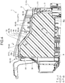
- FIG. 4 is a cross-sectional view taken along line A-A in FIG. 2 .
- FIG. 5 is a cross-sectional view taken along line B-B in FIG. 4 .
- FIG. 6 is a cross-sectional view taken along line C-C in FIG. 4 .
- FIG. 7 is a cross-sectional view taken along line D-D in FIG. 4 .
- FIG. 8 is a cross-sectional view taken along line E-E in FIG. 2 .
- upper and lower directions Z, first orthogonal directions X, and second orthogonal directions Y are orthogonal to each other.
- the electrical connection box 1 is mounted in a vehicle, and the vehicle is positioned on a horizontal plane, the first orthogonal directions X and the second orthogonal directions Y extend in horizontal directions.
- the upper and lower directions Z correspond to directions in which, when the electrical connection box 1 is mounted in the vehicle, and the vehicle is positioned on the horizontal plane, the vehicle vibrates, and correspond to stacking directions of the housing main body 3, a bottom body 4, and the lid body 5, described later.
- Directions used below are described as, unless otherwise stated, directions in which parts are assembled with each other, and the electrical connection box 1 is mounted in the vehicle.
- the electrical connection box 1 according to the present embodiment illustrated in FIGS. 1 , 2 , and 3 is mounted in a vehicle such as a car, and assembled to a wire harness WH1.
- the wire harness WH1 serves as an assembly that is bundled with a plurality of wiring materials W used for electric power supply and signal communications, and that uses connectors, for example, to couple the wiring materials W with electronic components D.
- the wire harness WH1 includes the wiring materials W each having an electrically conductive property, and the electrical connection box 1 electrically coupled to the wiring materials W.
- the wiring materials W include, for example, metallic bars, electric wires, and electric wire bundles.
- a metallic bar is one having a bar-shaped member having an electrically conductive property externally covered with a cover having an electrically insulating property.
- An electric wire is one having a conductor (core wire) including a plurality of metallic element wires having an electrically conductive property externally covered with a cover having an electrically insulating property.
- An electric wire bundle is one having the electric wires described above bundled. In FIGS. 1 and 2 , some of the wiring materials W are illustrated with solid lines, the rest of the wiring materials W are illustrated with virtual lines, and, in other drawings, the wiring materials W are omitted.
- the wiring materials W are bundled in an integrated manner, and are electrically coupled to the electrical connection box 1 via connectors, for example, provided at ends of the wiring materials W that are bundled.
- the wire harness WH1 may further include grommets, protectors, exterior materials, and fixtures, for example.
- the electrical connection box 1 accommodates in an integrated manner the electronic components D including connectors, fuses, relays, capacitors, and an electronic control unit, for example.
- the electrical connection box 1 is provided in an engine compartment or a cabin of the vehicle, for example.
- a region R (a region hatched with oblique lines in FIG. 3 ) is set. In the region R, when a pressure washer is used to wash the vehicle, or when the vehicle runs in heavy rain, pressurized or splashed water may hit a housing outer circumferential wall 31 described later for a long period of time.
- the region R is positioned closer to one side than a center in the first orthogonal directions X, and is positioned closer to another side than a center in the second orthogonal directions Y, for example.
- pressurized or splashed water is not assumed to hit the housing outer circumferential wall 31 for a long period of time.
- water stays in a space part S2 described later, and, when the water flows in the space part S2, the water flows from the one side toward another side in the first orthogonal directions X. That is, in FIG.
- the first orthogonal directions X include the water flow direction X1 and an opposite direction X2.
- a first electric power supply P1 and a second electric power supply P2 are electrically coupled, via the wiring materials W, for example, to the electronic devices mounted in the vehicle.
- the first electric power supply P1 is either of the battery and the alternator
- the second electric power supply P2 is the other of the battery and the alternator.
- the electrical connection box 1 distributes electric power that the electric power supplies P1 and P2 supply to the electronic devices in the vehicle.
- the electrical connection box 1 is sometimes referred to as a junction box, a fuse box, or a relay box, for example, and, in the present embodiment, the boxes are collectively referred to as the electrical connection box 1.
- the configuration of the electrical connection box 1 will now be described in detail with reference to the accompanying drawings. Specifically, the electrical connection box 1 includes the electronic components D, the housing B, and blocks 2.
- the electronic components D are, as illustrated in FIG. 3 , parts assembled to the blocks 2 and provided in the housing B to exert various functions.
- the electronic components D are provided in plurality in an accommodation space S1, and are each electrically coupled to the wiring materials W.
- the electronic components D include, for example, capacitors, relays, resistors, transistors, fuses, connectors, intelligent power switches (IPSs), and microcomputers.
- the electrical connection box 1 according to the present embodiment includes at least one of the electronic components D.
- the housing B accommodates, in the accommodation space S1 that is formed therein, the blocks 2 assembled with the electronic components D.
- the housing B includes, as illustrated in FIG. 1 , the housing main body 3 serving as a frame, the bottom body 4 serving as a lower cover, and the lid body 5 serving as an upper cover, for example.
- the housing B has a three-layered, divided structure divided into the housing main body 3, the bottom body 4, and the lid body 5.
- the housing main body 3, the bottom body 4, and the lid body 5 are made of synthetic resin having an electrically insulating property.
- the housing main body 3, the bottom body 4, and the lid body 5 are stacked and assembled with each other in the housing B in the predetermined stacking directions (the upper and lower directions Z as an example in here).
- the housing main body 3, the bottom body 4, and the lid body 5 as a plurality of members are assembled with each other and the housing B is formed into a hollow box shape as a whole.
- the housing main body 3, the bottom body 4, and the lid body 5 internally form spaces in the housing B.
- the accommodation space S1 is a space that accommodates the electronic components D.
- the housing main body 3 forms the accommodation space S1, for example.
- the housing B according to the present embodiment includes a plurality of compartments S11 that are positioned adjacent to a housing inner circumferential wall 32.
- the compartments S11 include a first compartment Slle provided with the electronic components D that are able to accept electric power, and a second compartment Slln provided with the electronic components D that are able to accept electric power.
- the second compartment Slln is provided with the electronic components D that are spare components and are thus not supplied with electric power, for example.
- the compartments S11 are disposed in the accommodation space S1.
- the wiring materials W are wired in the accommodation space S1 through an insertion hole 36 (see FIG. 1 ) formed in the housing main body 3.
- the blocks 2 described later are provided in the accommodation space S1, and the wiring materials W are coupled to the blocks 2.
- the blocks 2 are configured to be mountable with the electronic components D, and are detachably assembled to the housing B.
- the blocks 2 are made of synthetic resin having an electrically insulating property.
- the blocks 2 are provided in plurality in the housing B, for example.
- the wiring materials W and the electronic components D are assembled, and the wiring materials W are electrically coupled to the electronic components D.
- terminals provided at the ends of the wiring materials W are inserted and fitted from one side (a side on which the bottom body 4 is positioned, typically) in the upper and lower directions Z.
- the electronic components D are inserted and fitted from another side (a side on which the lid body 5 is positioned, typically) in the upper and lower directions Z.
- the housing main body 3 is a main member forming the housing B.
- the housing main body 3 is, as illustrated in FIG. 4 , formed into a frame shape having, on its two surfaces facing each other in the upper and lower directions Z, opening parts 30a and 30b.
- the housing main body 3 is formed into the frame shape having the opening parts 30a and 30b.
- the housing main body 3 described above has the accommodation space S1 that accommodates the electronic components D.
- the bottom body 4 is a dish-shaped (tray-shaped) member covering the opening part 30a that is positioned on a lower side, in the upper and lower directions Z, of the housing main body 3. That is, the bottom body 4 is stacked under the housing main body 3 in the upper and lower directions Z to seal the opening part 30a.
- the lid body 5 is a lid-shaped (cover-shaped) member covering the opening part 30b that is positioned on an upper side, in the upper and lower directions Z, of the housing main body 3.
- the lid body 5 is stacked upward on the housing main body 3 in the upper and lower directions Z to seal the opening part 30b.
- one of the opening parts of the housing main body 3, that is, the opening part 30a is positioned to face the bottom body 4, and the other of the opening parts of the housing main body 3, that is, the opening part 30b, is positioned to face the lid body 5.
- the bottom body 4 is assembled on the lower side, in the upper and lower directions Z, of the housing main body 3, and the lid body 5 is assembled on the upper side, in the upper and lower directions Z, of the housing main body 3.
- the housing B includes, as illustrated in FIGS.
- the blocks 2 assembled to the housing main body 3 have, as illustrated in FIG. 3 , partition walls 7 that internally partition the accommodation space S1.
- the partition walls 7 are provided in plurality in the accommodation space S1.
- the partition walls 7 include a first partition wall 71 and a second partition wall 72 that partition the first compartment Slle and the second compartment Slln described later.
- the housing main body 3 has, as illustrated in FIG. 5 , the housing outer circumferential wall 31, and the housing inner circumferential wall 32 that is positioned inside of the housing outer circumferential wall 31.
- the housing B according to the present embodiment further includes housing couplers 33 (see FIG. 8 ) that couple the housing outer circumferential wall 31 and the housing inner circumferential wall 32.
- the housing outer circumferential wall 31 has an upper end part 31U at its upper end part in the upper and lower directions Z.
- the housing outer circumferential wall 31 and the housing inner circumferential wall 32 are each formed into a plate shape, forming a double-structured housing wall part.
- the housing B has, as illustrated in FIG. 3 , corner parts C1 and C2 that are positioned between a part 38 where the housing outer circumferential wall 31 and the housing inner circumferential wall 32 extend in a straight line in the first orthogonal directions X and parts 39a and 39b where the housing outer circumferential wall 31 and the housing inner circumferential wall 32 extend in a straight line in the second orthogonal directions Y. That is, the housing B according to the present embodiment has two corner parts C that are positioned between the part 38 where the housing outer circumferential wall 31 and the housing inner circumferential wall 32 extend in the first orthogonal directions X and the parts 39a and 39b where the housing outer circumferential wall 31 and the housing inner circumferential wall 32 extend in the second orthogonal directions Y.
- one of the two corner parts C that is, the corner part C1
- the corner part C2 is disposed outside of the region R.
- the upper end part 31U of the housing outer circumferential wall 31 has, as illustrated in FIG. 4 , an inclined part 31I that is inclined from the one side toward the other side in the first orthogonal directions X and from the lower side toward the upper side in the upper and lower directions Z, and flat parts 31F1 and 31F2 that are flat in the upper and lower directions Z.
- the inclination angle of the inclined part 31I of the housing outer circumferential wall 31 according to the present embodiment is constant relative to the horizontal plane.
- one corner part that is, the corner part C1
- the other corner part that is, the corner part C2
- the flat part 31F2 is disposed on the flat part 31F2 that is positioned closer to the upper side in the upper and lower directions Z.
- the lid body 5 has, as illustrated in FIG. 1 , a top board 50 having a lid shape, a lid body outer circumferential wall 51 that projects from a circumferential part of the top board 50 toward the housing main body 3 in the upper and lower directions Z, a lid body inner circumferential wall 52 (see FIG. 5 ) that is positioned inside of the lid body outer circumferential wall 51, and that surrounds, with the lid body outer circumferential wall 51, the housing outer circumferential wall 31 that is inserted, and ribs 6 that couple the lid body outer circumferential wall 51 and the lid body inner circumferential wall 52 (see FIGS. 4 , 6 , and 7 ).
- the lid body outer circumferential wall 51 and the lid body inner circumferential wall 52 are each formed into a plate shape, forming a double-structured lid body wall part.
- the lid body inner circumferential wall 52 has a lower end part 52D at its lower end part in the upper and lower directions Z.
- the lid body outer circumferential wall 51, the lid body inner circumferential wall 52, and the upper end part 31U of the housing outer circumferential wall 31 form the space part S2 that surrounds the accommodation space S1.
- a gap S3 is formed between the lid body inner circumferential wall 52 and the housing outer circumferential wall 31.
- the housing couplers 33 are, as illustrated in FIG. 8 , at least provided to be spaced from each other in the first orthogonal directions X, and the housing couplers 33, the housing outer circumferential wall 31, and the housing inner circumferential wall 32 form a discharge space S4 that is in communication with the space part S2 via the gap S3 and that extends downward.
- the bottom body 4 has a bottom body plate 40 having a dish shape, and a bottom body outer circumferential wall 41 that projects from a circumferential part of the bottom body plate 40 toward the housing main body 3 in the upper and lower directions Z.
- the bottom body 4 further has, similarly to the lid body 5, a bottom body inner circumferential wall that is positioned inside of the bottom body outer circumferential wall 41, and that surrounds, with the bottom body outer circumferential wall 41, the housing outer circumferential wall 31 that is inserted, and bottom body ribs that couple the bottom body outer circumferential wall 41 and the bottom body inner circumferential wall.
- the bottom body outer circumferential wall 41 and the bottom body inner circumferential wall are each formed into a plate shape, forming a double-structured lid body wall part.
- the ribs 6 restrict both the lid body outer circumferential wall 51 and the lid body inner circumferential wall 52 from moving in position in the first orthogonal directions X and the second orthogonal directions Y.
- the ribs 6 described above are, as illustrated in FIGS. 4 , 6 , and 7 , provided to be spaced in the circumferential directions of the space part S2. That is, in the housing B and the electrical connection box 1 according to the present embodiment, the ribs 6 are provided to be spaced from each other at least in the first orthogonal directions X.
- the ribs 6 described above include a sealing rib 61, and area reduction ribs 62 that are reduced in area as compared with the sealing rib 61.
- the sealing rib 61 seals the space part S2 described above.
- the sealing rib 61 preferably seals the space part S2 as much as possible.
- a small space is formed between the sealing rib 61 according to the present embodiment and the upper end part 31U of the housing outer circumferential wall 31.
- the space falls within a range of error, and, even when such a space as described above is present at a middle location in the water flow direction X1, an amount of water that passes through the sealing rib 61 from a downstream side toward an upstream side in the water flow direction X1 is negligible, disallowing the water to enter the accommodation space S1.
- a first side S12a (see FIG. 3 ) that extends in the first orthogonal directions X, among sides S12 that form a circumference of the accommodation space S1, has one sealing rib, that is, the sealing rib 61.
- the sealing rib 61 is positioned outside of the accommodation space S1 in the second compartment Slln in the second orthogonal directions Y. To describe more specifically, the sealing rib 61 is disposed at a boundary between the first compartment Slle and the second compartment Slln in the water flow direction X1.
- the expression "the sealing rib 61 is positioned outside of the accommodation space S1 in the second compartment Slln in the second orthogonal directions Y" includes a state where the second compartment Slln and the sealing rib 61 face each other in the second orthogonal directions Y, and a state where the first compartment Slle and the second compartment Slln are positioned adjacent to each other in the first orthogonal directions X, and the sealing rib 61 is positioned at the boundary between the first compartment Slle and the second compartment Slln.
- the compartments S11 include the first compartment Slle that is positioned on the downstream side of the sealing rib 61, and the second compartment Slln that is positioned on the upstream side of the sealing rib 61 in the water flow direction X1.
- the corner part C2 is positioned on the downstream side of the first compartment Slle in the water flow direction X1, and is disposed on the flat part 31F2.
- the first compartment Slle is disposed adjacent to the corner part C2.
- the sealing rib 61 is disposed between the inclined part 31I and the flat part 31F2.
- the area reduction ribs 62 reduce the space part S2 in area.
- the area reduction ribs 62 are at least positioned on the upstream side of the sealing rib 61 in the water flow direction X1.
- the area reduction ribs 62 are provided in plurality on the upstream side of the sealing rib 61.
- the area reduction ribs 62 described above are not present on the downstream side of the sealing rib 61 in the water flow direction X1.
- pressurized or splashed water hits the housing outer circumferential wall 31 described above.
- Pressurized or splashed water is assumed to hit the region R illustrated in FIG. 3 for a long period of time, and pressurized or splashed water is not assumed to hit other regions than the region R for a long period of time.
- the water in the space part S2 comes into contact with the area reduction ribs 62, the water is discharged to the outside of the housing B.
- the water in the space part S2 comes into contact with the sealing rib 61, the water is then discharged to the second compartment Slln that is not provided with the electronic components D that are able to accept electric power, in the accommodation space S1.
- water may further stay in the space part S2 in a housing that does not have the sealing rib 61, resulting in that the water reaches the corner part C2.
- the housing B and the electrical connection box 1 according to the present embodiment are configured as described below.
- the housing B has the housing outer circumferential wall 31, and the housing inner circumferential wall 32 that is positioned inside of the housing outer circumferential wall 31, and the housing outer circumferential wall 31 is positioned between the lid body outer circumferential wall 51 and the lid body inner circumferential wall 52. Therefore, water flowing in the space part S2 is prevented from coming over the upper end part 31U of the housing inner circumferential wall 32, and the housing inner circumferential wall 32 can prevent water from entering the accommodation space S1.
- the housing B and the electrical connection box 1 are configured as described below.
- the compartments S11 include the first compartment Slle that is positioned on the downstream side of the sealing rib 61 in the water flow direction X1 in which, when water enters the space part S2, the water flows, among the first orthogonal directions X, and that is provided with the electronic components D that are able to accept electric power, and the second compartment Slln that is positioned on the upstream side of the sealing rib 61, and that is not provided with the electronic components D that are able to accept electric power.
- the sealing rib 61 is positioned outside of the accommodation space S1 in the second compartment Slln in the second orthogonal directions Y.
- the housing B and the electrical connection box 1 allow the sealing rib 61 to prevent water from flowing toward the downstream side of the sealing rib 61. Therefore, on the downstream side of the sealing rib 61, it is possible to prevent water from entering the accommodation space S1. Even when such a state that water hits the housing outer circumferential wall 31 continues for a long period of time, and the water flows in the space part S2, the sealing rib 61 prevents the water in the space part S2 from flowing further, discharging the water toward outside of the accommodation space S1, on outside of the second compartment Slln that is not provided with the electronic components D that are able to accept electric power.
- the housing B and the electrical connection box 1 according to the present embodiment make it possible to prevent water from coming into contact with the electronic components D that are able to accept electric power.
- the housing B and the electrical connection box 1 according to the present embodiment make it possible to control a location at which water may enter the accommodation space S1, making it possible to reduce the occurrence of such an event that the electronic components D that are able to accept electric power are affected.
- the housing B and the electrical connection box 1 according to the present embodiment are configured as described below.
- the housing B has the corner part C2 that is positioned between the part 38 where the housing outer circumferential wall 31 and the housing inner circumferential wall 32 extend in the first orthogonal directions X and the part 39b where the housing outer circumferential wall 31 and the housing inner circumferential wall 32 extend in the second orthogonal directions Y.
- the corner part C2 is positioned on the downstream side of the first compartment Slle in the water flow direction X1. Therefore, in the housing B and the electrical connection box 1 according to the present embodiment, the sealing rib 61 is positioned on the upstream side of the corner part C2 in the water flow direction X1.
- the sealing rib 61 prevents the water from flowing further, and thus prevents the water from reaching the corner part C2, making it possible to further reduce the occurrence of such an event that the electronic components D that are able to accept electric power are affected.
- the housing B and the electrical connection box 1 according to the present embodiment are configured as described below.
- the upper end part 31U of the housing outer circumferential wall 31 has the inclined part 31I that is inclined from the one side toward the other side in the first orthogonal directions X and from the lower side toward the upper side in the upper and lower directions Z.
- the sealing rib 61 is positioned at a middle location of the inclined part 31I, or on the downstream side of the inclined part 31I in the water flow direction X1. Therefore, the housing B and the electrical connection box 1 according to the present embodiment make it possible to use the inclined part 31I and gravity to reduce an amount of water reaching the sealing rib 61. As a result, the housing B and the electrical connection box 1 according to the present embodiment make it possible to further reduce the occurrence of such an event that the electronic components D that are able to accept electric power are affected.
- the housing B and the electrical connection box 1 according to the present embodiment are configured as described below.
- the ribs 6 include the area reduction ribs 62 that reduce the space part S2 in area.
- the area reduction ribs 62 are positioned on the upstream side of the sealing rib 61 in the water flow direction X1.
- water flowing from the one side toward the other side in the first orthogonal directions X comes into contact with the area reduction ribs 62 before reaching the sealing rib 61, allowing the area reduction ribs 62 to reduce an amount of water reaching the sealing rib 61.
- the housing B and the electrical connection box 1 according to the present embodiment make it possible to further reduce the occurrence of such an event that the electronic components D that are able to accept electric power are affected.
- the housing B and the electrical connection box 1 according to the present embodiment are configured as described below.
- the housing main body 3 further has the housing couplers 33 that couple the housing outer circumferential wall 31 and the housing inner circumferential wall 32.
- the housing couplers 33 are provided to be spaced from each other in the first orthogonal directions X, and the housing couplers 33, the housing outer circumferential wall 31, and the housing inner circumferential wall 32 form the discharge space S4 that is in communication with the space part S2 via the gap S3 and that extends downward. Therefore, in the housing B and the electrical connection box 1 according to the present embodiment, even when water flows in the space part S2, it is possible to discharge the water in the space part S2 toward outside of the accommodation space S1 via the gap S3 and the discharge space S4. As a result, the housing B and the electrical connection box 1 according to the present embodiment make it possible to suppress water from entering the accommodation space S1, making it possible to further reduce the occurrence of such an event that the electronic components D that are able to accept electric power are affected
- housing B and the electrical connection box 1 according to the embodiment described above are not limited to the embodiment described above, but various modifications can be made within the scope of the claims.
- the housing B and the electrical connection box 1 according to the embodiment described above have one sealing rib, that is, the sealing rib 61.
- the housing B and the electrical connection box 1 according to the present embodiment are not limited to the configuration, but may include a plurality of the sealing ribs 61.
- the sealing rib 61 is disposed at the boundary between the first compartment Slle and the second compartment Slln in the water flow direction X1.
- the present invention is not limited to the configuration, but the sealing rib 61 only needs to seal the space part S2 that is positioned outside of the accommodation space S1 in which the second compartment Slln is positioned in the second orthogonal directions Y.
- the area reduction ribs 62 are provided on the lid body 5.
- the present invention is not limited to the configuration, but the area reduction ribs 62 may not be provided on the lid body 5.
- the housing B includes the housing main body 3, the bottom body 4, and the lid body 5.
- the embodiment is not limited to the configuration, and the housing main body 3 and the bottom body 4 may be integrally formed, and the housing B may include the integrally formed housing main body 3 and bottom body 4 described above and the lid body 5.
- the housing B has been described where the inclined part 31I of the housing outer circumferential wall 31 has the inclination angle that is constant relative to the horizontal plane.
- the embodiment is not limited to the configuration, but the inclination angle relative to the horizontal plane may gradually increase or decrease, or may be set in another way.
- the gap S3 is formed between the lid body inner circumferential wall 52 and the housing outer circumferential wall 31.
- the embodiment is not limited to the configuration, but the gap S3 may be formed between the lid body outer circumferential wall 51 and the housing outer circumferential wall 31 in the housing B and the electrical connection box 1. That is, in the housing B according to the present embodiment, the gap S3 should be formed at least either between the lid body outer circumferential wall 51 and the housing outer circumferential wall 31 or between the lid body inner circumferential wall 52 and the housing outer circumferential wall 31.
- An accommodation space includes a plurality of compartments that are positioned adjacent to a housing inner circumferential wall.
- the compartments include a first compartment that is positioned on a downstream side of a sealing rib in a water flow direction in which, when water enters a space part, the water flows, among first orthogonal directions, and that is provided with electronic components that are able to accept electric power, and a second compartment that is positioned on an upstream side of the sealing rib, and that is not provided with the electronic components that are able to accept electric power.
- the sealing rib is positioned outside of the accommodation space in the second compartment in second orthogonal directions orthogonal to each of the upper and lower directions and the first orthogonal directions.
Description
- The present invention relates to a housing and an electrical connection box.
- An electrical connection box mounted in a vehicle accommodates in an integrated manner, in an accommodation space therein, electronic components including connectors, fuses, relays, and capacitors, for example. Such an electrical connection box includes a housing including a housing main body that is formed into a frame shape having an opening part, and that has an accommodation space therein that accommodates electronic components, and a lid body that is stacked upward on the housing main body in upper and lower directions, and that seals the opening part (e.g., see
US2017070040 ). - A housing main body of this kind includes a housing outer circumferential wall that extends in circumferential directions, and a housing inner circumferential wall that is positioned inside of the housing outer circumferential wall to configure a double-structured circumferential wall part (e.g., see
Japanese Patent Application Laid-open No. 2019-198145 - However, when a pressure washer is used to wash the vehicle, or when the vehicle runs in heavy rain, for example, pressurized or splashed water may hit the housing outer circumferential wall of such a housing. If such a state that water hits the housing outer circumferential wall of the housing continues for a long period of time, the water may move upward on a surface of the housing outer circumferential wall, and the water may then reach an upper end part of the housing outer circumferential wall. Such water may enter a space part that surrounds the accommodation space that the lid body outer circumferential wall, the lid body inner circumferential wall, and the upper end part of the housing outer circumferential wall form, and that accommodates the electronic components, and the water may then flow in the space part. When such a state that the water hits the housing outer circumferential wall that is positioned on one side in first orthogonal directions orthogonal to the upper and lower directions continues for a long period of time, the water may flow in the space part described above from the one side toward the other side in the first orthogonal directions, and may enter the accommodation space that is positioned in the housing main body. At this time, since, with the conventional electrical connection box, water flows in the space part, it is difficult to identify a location at which the water will enter the accommodation space.
- The present invention has been made in view of the issues described above, and an object of the present invention is to provide a housing and an electrical connection box that control a location at which water may enter an accommodation space, making it possible to reduce the occurrence of such an event that electronic components that are able to accept electric power are affected.
- In order to achieve the above mentioned object, a housing according to one aspect of the present invention includes a housing main body that is formed into a frame shape having an opening part, and that has an accommodation space accommodating electronic components therein; and a lid body that is stacked upward on the housing main body in upper and lower directions, and that seals the opening part, wherein the housing main body has a housing outer circumferential wall, and a housing inner circumferential wall that is positioned inside of the housing outer circumferential wall, the lid body has a top board having a plate shape, a lid body outer circumferential wall that projects from a circumferential part of the top board toward the housing main body in the upper and lower directions, a lid body inner circumferential wall that is positioned inside of the lid body outer circumferential wall, and that surrounds, with the lid body outer circumferential wall, the housing outer circumferential wall that is inserted, and ribs that couple the lid body outer circumferential wall and the lid body inner circumferential wall, the accommodation space includes a plurality of compartments that are positioned adjacent to the housing inner circumferential wall, the lid body outer circumferential wall, the lid body inner circumferential wall, and an upper end part of the housing outer circumferential wall form a space part that surrounds the accommodation space, a gap is formed at least either between the lid body outer circumferential wall and the housing outer circumferential wall and between the lid body inner circumferential wall and the housing outer circumferential wall, the ribs include a sealing rib that is disposed and spaced in first orthogonal directions orthogonal to the upper and lower directions, and that seals the space part, the compartments include a first compartment that is positioned on a downstream side of the sealing rib in a water flow direction in which, when water enters the space part, the water flows, among the first orthogonal directions, and that is provided with the electronic components capable of accepting electric power, and a second compartment that is positioned on an upstream side of the sealing rib, and that is not provided with the electronic components capable of accepting electric power, and the sealing rib is positioned outside of the accommodation space in the second compartment in the second orthogonal directions orthogonal to the upper and lower directions and the first orthogonal directions.
- According to another aspect of the present invention, in the housing, it is preferable that the housing has a corner part positioned between a part where the housing outer circumferential wall and the housing inner circumferential wall extend in the first orthogonal directions and a part where the housing outer circumferential wall and the housing inner circumferential wall extend in the second orthogonal directions, and the corner part is positioned on the downstream side of the first compartment in the water flow direction.
- According to still another aspect of the present invention, in the housing, it is preferable that the upper end part of the housing outer circumferential wall has an inclined part that is inclined from one side toward another side in the first orthogonal directions and from a lower side toward an upper side in the upper and lower directions, and a flat part that is flat in the upper and lower directions, the sealing rib is disposed between the inclined part and the flat part, the first compartment is disposed adjacent to the corner part, and the corner part is disposed on the flat part.
- According to still another aspect of the present invention, in the housing, it is preferable that the ribs include area reduction ribs that reduce the space part in area, and the area reduction ribs are positioned on the upstream side of the sealing rib in the water flow direction.
- According to still another aspect of the present invention, in the housing, it is preferable that the housing main body further has housing couplers that couple the housing outer circumferential wall and the housing inner circumferential wall, the housing couplers are provided to be spaced from each other in the first orthogonal directions, and the housing couplers, the housing outer circumferential wall, and the housing inner circumferential wall form a discharge space that is in communication with the space part via the gap and that extends downward.
- In order to achieve the above mentioned object, an electrical connection box according to still another aspect of the present invention includes at least one or more electronic components; and a housing that accommodates the electronic components in an accommodation space therein, wherein the housing includes a housing main body that is formed into a frame shape having an opening part, and that has the accommodation space accommodating electronic components therein, and a lid body that is stacked upward on the housing main body in upper and lower directions, and that seals the opening part, the housing main body has a housing outer circumferential wall, and a housing inner circumferential wall that is positioned inside of the housing outer circumferential wall, the lid body has a top board having a plate shape, a lid body outer circumferential wall that projects from a circumferential part of the top board toward the housing main body in the upper and lower directions, a lid body inner circumferential wall that is positioned inside of the lid body outer circumferential wall, and that surrounds, with the lid body outer circumferential wall, the housing outer circumferential wall that is inserted, and ribs that couple the lid body outer circumferential wall and the lid body inner circumferential wall, the accommodation space includes a plurality of compartments that are positioned adjacent to the housing inner circumferential wall, the lid body outer circumferential wall, the lid body inner circumferential wall, and an upper end part of the housing outer circumferential wall form a space part that surrounds the accommodation space, a gap is formed at least either between the lid body outer circumferential wall and the housing outer circumferential wall and between the lid body inner circumferential wall and the housing outer circumferential wall, the ribs include a sealing rib that is disposed and spaced in first orthogonal directions orthogonal to the upper and lower directions, and that seals the space part, the compartments include a first compartment that is positioned on a downstream side of the sealing rib in a water flow direction in which, when water enters the space part, the water flows, among the first orthogonal directions, and that is provided with the electronic components capable of accepting electric power, and a second compartment that is positioned on an upstream side of the sealing rib, and that is not provided with the electronic components capable of accepting electric power, and the sealing rib is positioned outside of the accommodation space in the second compartment in the second orthogonal directions orthogonal to the upper and lower directions and the first orthogonal directions.
- The above and other objects, features, advantages and technical and industrial significance of this invention will be better understood by reading the following detailed description of presently preferred embodiments of the invention, when considered in connection with the accompanying drawings.
-
-
FIG. 1 is a perspective view illustrating a housing and an electrical connection box according to a present embodiment; -
FIG. 2 is a plan view illustrating the housing and the electrical connection box according to the present embodiment; -
FIG. 3 is a plan view illustrating a housing main body when a lid body is removed from the housing main body in the housing and the electrical connection box according to the present embodiment; -
FIG. 4 is a cross-sectional view taken along line A-A inFIG. 2 ; -
FIG. 5 is a cross-sectional view taken along line B-B inFIG. 4 ; -
FIG. 6 is a cross-sectional view taken along line C-C inFIG. 4 ; -
FIG. 7 is a cross-sectional view taken along line D-D inFIG. 4 ; and -
FIG. 8 is a cross-sectional view taken along line E-E inFIG. 2 . - An embodiment according to the present invention will now be described in detail with reference to the accompanying drawings. Note that the embodiment is not intended to limit the invention. Note that components in the embodiment described below include ones easily replaced by one skilled in the art or substantially identical ones.
-
FIG. 1 is a perspective view illustrating a housing B and anelectrical connection box 1 according to the embodiment.FIG. 2 is a plan view illustrating the housing B and theelectrical connection box 1 according to the embodiment.FIG. 3 is a plan view illustrating a housingmain body 3 when alid body 5 is removed from the housingmain body 3 in the housing B and theelectrical connection box 1 according to the embodiment.FIG. 4 is a cross-sectional view taken along line A-A inFIG. 2 .FIG. 5 is a cross-sectional view taken along line B-B inFIG. 4 .FIG. 6 is a cross-sectional view taken along line C-C inFIG. 4 . -
FIG. 7 is a cross-sectional view taken along line D-D inFIG. 4 .FIG. 8 is a cross-sectional view taken along line E-E inFIG. 2 . In the following description, upper and lower directions Z, first orthogonal directions X, and second orthogonal directions Y are orthogonal to each other. Furthermore, while theelectrical connection box 1 is mounted in a vehicle, and the vehicle is positioned on a horizontal plane, the first orthogonal directions X and the second orthogonal directions Y extend in horizontal directions. The upper and lower directions Z correspond to directions in which, when theelectrical connection box 1 is mounted in the vehicle, and the vehicle is positioned on the horizontal plane, the vehicle vibrates, and correspond to stacking directions of the housingmain body 3, abottom body 4, and thelid body 5, described later. Directions used below are described as, unless otherwise stated, directions in which parts are assembled with each other, and theelectrical connection box 1 is mounted in the vehicle. - The
electrical connection box 1 according to the present embodiment illustrated inFIGS. 1 ,2 , and3 is mounted in a vehicle such as a car, and assembled to a wire harness WH1. To couple electronic devices (not illustrated) mounted in the vehicle with each other, for example, the wire harness WH1 serves as an assembly that is bundled with a plurality of wiring materials W used for electric power supply and signal communications, and that uses connectors, for example, to couple the wiring materials W with electronic components D. The wire harness WH1 includes the wiring materials W each having an electrically conductive property, and theelectrical connection box 1 electrically coupled to the wiring materials W. The wiring materials W include, for example, metallic bars, electric wires, and electric wire bundles. - A metallic bar is one having a bar-shaped member having an electrically conductive property externally covered with a cover having an electrically insulating property. An electric wire is one having a conductor (core wire) including a plurality of metallic element wires having an electrically conductive property externally covered with a cover having an electrically insulating property. An electric wire bundle is one having the electric wires described above bundled. In
FIGS. 1 and2 , some of the wiring materials W are illustrated with solid lines, the rest of the wiring materials W are illustrated with virtual lines, and, in other drawings, the wiring materials W are omitted. In the wire harness WH1, the wiring materials W are bundled in an integrated manner, and are electrically coupled to theelectrical connection box 1 via connectors, for example, provided at ends of the wiring materials W that are bundled. In addition, the wire harness WH1 may further include grommets, protectors, exterior materials, and fixtures, for example. - The
electrical connection box 1 accommodates in an integrated manner the electronic components D including connectors, fuses, relays, capacitors, and an electronic control unit, for example. Theelectrical connection box 1 is provided in an engine compartment or a cabin of the vehicle, for example. To describe more specifically, in theelectrical connection box 1 according to the present embodiment, a region R (a region hatched with oblique lines inFIG. 3 ) is set. In the region R, when a pressure washer is used to wash the vehicle, or when the vehicle runs in heavy rain, pressurized or splashed water may hit a housing outercircumferential wall 31 described later for a long period of time. In theelectrical connection box 1 according to the present embodiment, the region R is positioned closer to one side than a center in the first orthogonal directions X, and is positioned closer to another side than a center in the second orthogonal directions Y, for example. For other regions than the region R in theelectrical connection box 1 according to the present embodiment, pressurized or splashed water is not assumed to hit the housing outercircumferential wall 31 for a long period of time. In the region R set in theelectrical connection box 1 according to the present embodiment, onto which pressurized or splashed water hits, water stays in a space part S2 described later, and, when the water flows in the space part S2, the water flows from the one side toward another side in the first orthogonal directions X. That is, inFIG. 3 , water flows, in a water flow direction X1, from a right-hand side, that is, the one side toward a left-hand side, that is, the other side in the first orthogonal directions X. The first orthogonal directions X include the water flow direction X1 and an opposite direction X2. - In the
electrical connection box 1, a first electric power supply P1 and a second electric power supply P2 (seeFIG. 1 ) are electrically coupled, via the wiring materials W, for example, to the electronic devices mounted in the vehicle. The first electric power supply P1 is either of the battery and the alternator, and the second electric power supply P2 is the other of the battery and the alternator. Theelectrical connection box 1 distributes electric power that the electric power supplies P1 and P2 supply to the electronic devices in the vehicle. Theelectrical connection box 1 is sometimes referred to as a junction box, a fuse box, or a relay box, for example, and, in the present embodiment, the boxes are collectively referred to as theelectrical connection box 1. The configuration of theelectrical connection box 1 will now be described in detail with reference to the accompanying drawings. Specifically, theelectrical connection box 1 includes the electronic components D, the housing B, and blocks 2. - The electronic components D are, as illustrated in
FIG. 3 , parts assembled to theblocks 2 and provided in the housing B to exert various functions. The electronic components D are provided in plurality in an accommodation space S1, and are each electrically coupled to the wiring materials W. The electronic components D include, for example, capacitors, relays, resistors, transistors, fuses, connectors, intelligent power switches (IPSs), and microcomputers. Theelectrical connection box 1 according to the present embodiment includes at least one of the electronic components D. - The housing B accommodates, in the accommodation space S1 that is formed therein, the
blocks 2 assembled with the electronic components D. The housing B includes, as illustrated inFIG. 1 , the housingmain body 3 serving as a frame, thebottom body 4 serving as a lower cover, and thelid body 5 serving as an upper cover, for example. The housing B has a three-layered, divided structure divided into the housingmain body 3, thebottom body 4, and thelid body 5. The housingmain body 3, thebottom body 4, and thelid body 5 are made of synthetic resin having an electrically insulating property. The housingmain body 3, thebottom body 4, and thelid body 5 are stacked and assembled with each other in the housing B in the predetermined stacking directions (the upper and lower directions Z as an example in here). With this configuration, the housingmain body 3, thebottom body 4, and thelid body 5 as a plurality of members are assembled with each other and the housing B is formed into a hollow box shape as a whole. The housingmain body 3, thebottom body 4, and thelid body 5 internally form spaces in the housing B. - Among the spaces formed in the housing B, the accommodation space S1 is a space that accommodates the electronic components D. The housing
main body 3 forms the accommodation space S1, for example. The housing B according to the present embodiment includes a plurality of compartments S11 that are positioned adjacent to a housing innercircumferential wall 32. The compartments S11 include a first compartment Slle provided with the electronic components D that are able to accept electric power, and a second compartment Slln provided with the electronic components D that are able to accept electric power. The second compartment Slln is provided with the electronic components D that are spare components and are thus not supplied with electric power, for example. In the housing B and theelectrical connection box 1 according to the present embodiment, the compartments S11 are disposed in the accommodation space S1. - In the
electrical connection box 1, for example, the wiring materials W are wired in the accommodation space S1 through an insertion hole 36 (seeFIG. 1 ) formed in the housingmain body 3. In theelectrical connection box 1, for example, theblocks 2 described later are provided in the accommodation space S1, and the wiring materials W are coupled to theblocks 2. - The
blocks 2 are configured to be mountable with the electronic components D, and are detachably assembled to the housing B. Theblocks 2 are made of synthetic resin having an electrically insulating property. Theblocks 2 are provided in plurality in the housing B, for example. - In the
blocks 2, the wiring materials W and the electronic components D are assembled, and the wiring materials W are electrically coupled to the electronic components D. For example, in cavities of theblocks 2, terminals provided at the ends of the wiring materials W are inserted and fitted from one side (a side on which thebottom body 4 is positioned, typically) in the upper and lower directions Z. On the other hand, in the cavities of theblocks 2, the electronic components D are inserted and fitted from another side (a side on which thelid body 5 is positioned, typically) in the upper and lower directions Z. With this configuration, the electronic components D and the wiring materials W are assembled and mounted in theblocks 2 and electrically coupled with each other, configuring required electric circuits. - The housing
main body 3 is a main member forming the housing B. The housingmain body 3 is, as illustrated inFIG. 4 , formed into a frame shape having, on its two surfaces facing each other in the upper and lower directions Z, openingparts - That is, the housing
main body 3 is formed into the frame shape having the openingparts main body 3 described above has the accommodation space S1 that accommodates the electronic components D. Thebottom body 4 is a dish-shaped (tray-shaped) member covering theopening part 30a that is positioned on a lower side, in the upper and lower directions Z, of the housingmain body 3. That is, thebottom body 4 is stacked under the housingmain body 3 in the upper and lower directions Z to seal theopening part 30a. Thelid body 5 is a lid-shaped (cover-shaped) member covering theopening part 30b that is positioned on an upper side, in the upper and lower directions Z, of the housingmain body 3. That is, thelid body 5 is stacked upward on the housingmain body 3 in the upper and lower directions Z to seal theopening part 30b. In the housing B, one of the opening parts of the housingmain body 3, that is, theopening part 30a, is positioned to face thebottom body 4, and the other of the opening parts of the housingmain body 3, that is, theopening part 30b, is positioned to face thelid body 5. In the housing B, under this positional relation, thebottom body 4 is assembled on the lower side, in the upper and lower directions Z, of the housingmain body 3, and thelid body 5 is assembled on the upper side, in the upper and lower directions Z, of the housingmain body 3. The housing B includes, as illustrated inFIGS. 1 and2 , lockmechanisms 35 in various styles, and, via thelock mechanisms 35, thebottom body 4 and thelid body 5 are locked to the housingmain body 3. With this configuration, the housing B is formed into a box shape as a whole. Theblocks 2 assembled to the housingmain body 3 have, as illustrated inFIG. 3 ,partition walls 7 that internally partition the accommodation space S1. Thepartition walls 7 are provided in plurality in the accommodation space S1. Thepartition walls 7 include afirst partition wall 71 and asecond partition wall 72 that partition the first compartment Slle and the second compartment Slln described later. - The housing
main body 3 has, as illustrated inFIG. 5 , the housing outercircumferential wall 31, and the housing innercircumferential wall 32 that is positioned inside of the housing outercircumferential wall 31. The housing B according to the present embodiment further includes housing couplers 33 (seeFIG. 8 ) that couple the housing outercircumferential wall 31 and the housing innercircumferential wall 32. The housing outercircumferential wall 31 has anupper end part 31U at its upper end part in the upper and lower directions Z. The housing outercircumferential wall 31 and the housing innercircumferential wall 32 are each formed into a plate shape, forming a double-structured housing wall part. - The housing B has, as illustrated in
FIG. 3 , corner parts C1 and C2 that are positioned between apart 38 where the housing outercircumferential wall 31 and the housing innercircumferential wall 32 extend in a straight line in the first orthogonal directions X andparts circumferential wall 31 and the housing innercircumferential wall 32 extend in a straight line in the second orthogonal directions Y. That is, the housing B according to the present embodiment has two corner parts C that are positioned between thepart 38 where the housing outercircumferential wall 31 and the housing innercircumferential wall 32 extend in the first orthogonal directions X and theparts circumferential wall 31 and the housing innercircumferential wall 32 extend in the second orthogonal directions Y. In the housing B according to the present embodiment, one of the two corner parts C, that is, the corner part C1, is disposed inside of the region R, and the other one, that is, the corner part C2, is disposed outside of the region R. - The
upper end part 31U of the housing outercircumferential wall 31 has, as illustrated inFIG. 4 , an inclined part 31I that is inclined from the one side toward the other side in the first orthogonal directions X and from the lower side toward the upper side in the upper and lower directions Z, and flat parts 31F1 and 31F2 that are flat in the upper and lower directions Z. The inclination angle of the inclined part 31I of the housing outercircumferential wall 31 according to the present embodiment is constant relative to the horizontal plane. In theupper end part 31U of the housing outercircumferential wall 31 according to the present embodiment, one corner part, that is, the corner part C1, is disposed on the flat part 31F1 that is positioned closer to the lower side in the upper and lower directions Z, and the other corner part, that is, the corner part C2, is disposed on the flat part 31F2 that is positioned closer to the upper side in the upper and lower directions Z. - The
lid body 5 has, as illustrated inFIG. 1 , atop board 50 having a lid shape, a lid body outercircumferential wall 51 that projects from a circumferential part of thetop board 50 toward the housingmain body 3 in the upper and lower directions Z, a lid body inner circumferential wall 52 (seeFIG. 5 ) that is positioned inside of the lid body outercircumferential wall 51, and that surrounds, with the lid body outercircumferential wall 51, the housing outercircumferential wall 31 that is inserted, andribs 6 that couple the lid body outercircumferential wall 51 and the lid body inner circumferential wall 52 (seeFIGS. 4 ,6 , and7 ). The lid body outercircumferential wall 51 and the lid body innercircumferential wall 52 are each formed into a plate shape, forming a double-structured lid body wall part. The lid body innercircumferential wall 52 has alower end part 52D at its lower end part in the upper and lower directions Z. - In the housing B, as illustrated in
FIGS. 4 ,5 ,6 , and7 , the lid body outercircumferential wall 51, the lid body innercircumferential wall 52, and theupper end part 31U of the housing outercircumferential wall 31 form the space part S2 that surrounds the accommodation space S1. - In the housing B according to the present embodiment, as illustrated in
FIGS. 5 ,6 , and7 , a gap S3 is formed between the lid body innercircumferential wall 52 and the housing outercircumferential wall 31. - The
housing couplers 33 are, as illustrated inFIG. 8 , at least provided to be spaced from each other in the first orthogonal directions X, and thehousing couplers 33, the housing outercircumferential wall 31, and the housing innercircumferential wall 32 form a discharge space S4 that is in communication with the space part S2 via the gap S3 and that extends downward. - The
bottom body 4 has abottom body plate 40 having a dish shape, and a bottom body outercircumferential wall 41 that projects from a circumferential part of thebottom body plate 40 toward the housingmain body 3 in the upper and lower directions Z. Although not illustrated, thebottom body 4 further has, similarly to thelid body 5, a bottom body inner circumferential wall that is positioned inside of the bottom body outercircumferential wall 41, and that surrounds, with the bottom body outercircumferential wall 41, the housing outercircumferential wall 31 that is inserted, and bottom body ribs that couple the bottom body outercircumferential wall 41 and the bottom body inner circumferential wall. The bottom body outercircumferential wall 41 and the bottom body inner circumferential wall are each formed into a plate shape, forming a double-structured lid body wall part. - The
ribs 6 restrict both the lid body outercircumferential wall 51 and the lid body innercircumferential wall 52 from moving in position in the first orthogonal directions X and the second orthogonal directions Y. Theribs 6 described above are, as illustrated inFIGS. 4 ,6 , and7 , provided to be spaced in the circumferential directions of the space part S2. That is, in the housing B and theelectrical connection box 1 according to the present embodiment, theribs 6 are provided to be spaced from each other at least in the first orthogonal directions X. Theribs 6 described above include a sealingrib 61, andarea reduction ribs 62 that are reduced in area as compared with the sealingrib 61. - The sealing
rib 61 seals the space part S2 described above. The sealingrib 61 preferably seals the space part S2 as much as possible. However, as illustrated inFIG. 6 , a small space is formed between the sealingrib 61 according to the present embodiment and theupper end part 31U of the housing outercircumferential wall 31. However, the space falls within a range of error, and, even when such a space as described above is present at a middle location in the water flow direction X1, an amount of water that passes through the sealingrib 61 from a downstream side toward an upstream side in the water flow direction X1 is negligible, disallowing the water to enter the accommodation space S1. In the housing B and theelectrical connection box 1 according to the present embodiment, a first side S12a (seeFIG. 3 ) that extends in the first orthogonal directions X, among sides S12 that form a circumference of the accommodation space S1, has one sealing rib, that is, the sealingrib 61. The sealingrib 61 is positioned outside of the accommodation space S1 in the second compartment Slln in the second orthogonal directions Y. To describe more specifically, the sealingrib 61 is disposed at a boundary between the first compartment Slle and the second compartment Slln in the water flow direction X1. In the present embodiment, the expression "the sealingrib 61 is positioned outside of the accommodation space S1 in the second compartment Slln in the second orthogonal directions Y" includes a state where the second compartment Slln and the sealingrib 61 face each other in the second orthogonal directions Y, and a state where the first compartment Slle and the second compartment Slln are positioned adjacent to each other in the first orthogonal directions X, and the sealingrib 61 is positioned at the boundary between the first compartment Slle and the second compartment Slln. Since the sealingrib 61, the first compartment Slle, and the second compartment Slln are configured as described above, the compartments S11 include the first compartment Slle that is positioned on the downstream side of the sealingrib 61, and the second compartment Slln that is positioned on the upstream side of the sealingrib 61 in the water flow direction X1. The corner part C2 is positioned on the downstream side of the first compartment Slle in the water flow direction X1, and is disposed on the flat part 31F2. Furthermore, the first compartment Slle is disposed adjacent to the corner part C2. Furthermore, the sealingrib 61 is disposed between the inclined part 31I and the flat part 31F2. - The
area reduction ribs 62 reduce the space part S2 in area. Thearea reduction ribs 62 are at least positioned on the upstream side of the sealingrib 61 in the water flow direction X1. In the housing B and theelectrical connection box 1 according to the present embodiment, thearea reduction ribs 62 are provided in plurality on the upstream side of the sealingrib 61. Thearea reduction ribs 62 described above are not present on the downstream side of the sealingrib 61 in the water flow direction X1. - Next, a case where pressurized or splashed water hits the housing outer
circumferential wall 31 described above will be described. Pressurized or splashed water is assumed to hit the region R illustrated inFIG. 3 for a long period of time, and pressurized or splashed water is not assumed to hit other regions than the region R for a long period of time. - When pressurized or splashed water hits the housing outer
circumferential wall 31 and such a state continues for a long period of time, the water moves upward on an outer surface of the housing outercircumferential wall 31, and reaches theupper end part 31U of the housing outercircumferential wall 31. The water described above then stays in the space part S2. The water that stays in the space part S2 is discharged to the outside of the housing B through the gap S3 and the discharge space S4. However, if an amount of water that enters the space part S2 is greater than an amount of water that is discharged, water stays in the space part S2 on the flat part 31F1. If such a state continues, the water goes up the inclined part 31I having a rising gradient in the water flow direction X1. However, when the water in the space part S2 comes into contact with thearea reduction ribs 62, the water is discharged to the outside of the housing B. When the water in the space part S2 comes into contact with the sealingrib 61, the water is then discharged to the second compartment Slln that is not provided with the electronic components D that are able to accept electric power, in the accommodation space S1. Apart from the housing B according to the present embodiment that has the sealingrib 61, water may further stay in the space part S2 in a housing that does not have the sealingrib 61, resulting in that the water reaches the corner part C2. - The housing B and the
electrical connection box 1 according to the present embodiment are configured as described below. The housing B has the housing outercircumferential wall 31, and the housing innercircumferential wall 32 that is positioned inside of the housing outercircumferential wall 31, and the housing outercircumferential wall 31 is positioned between the lid body outercircumferential wall 51 and the lid body innercircumferential wall 52. Therefore, water flowing in the space part S2 is prevented from coming over theupper end part 31U of the housing innercircumferential wall 32, and the housing innercircumferential wall 32 can prevent water from entering the accommodation space S1. - The housing B and the
electrical connection box 1 according to the present embodiment are configured as described below. The compartments S11 include the first compartment Slle that is positioned on the downstream side of the sealingrib 61 in the water flow direction X1 in which, when water enters the space part S2, the water flows, among the first orthogonal directions X, and that is provided with the electronic components D that are able to accept electric power, and the second compartment Slln that is positioned on the upstream side of the sealingrib 61, and that is not provided with the electronic components D that are able to accept electric power. The sealingrib 61 is positioned outside of the accommodation space S1 in the second compartment Slln in the second orthogonal directions Y. Therefore, the housing B and theelectrical connection box 1 according to the present embodiment allow the sealingrib 61 to prevent water from flowing toward the downstream side of the sealingrib 61. Therefore, on the downstream side of the sealingrib 61, it is possible to prevent water from entering the accommodation space S1. Even when such a state that water hits the housing outercircumferential wall 31 continues for a long period of time, and the water flows in the space part S2, the sealingrib 61 prevents the water in the space part S2 from flowing further, discharging the water toward outside of the accommodation space S1, on outside of the second compartment Slln that is not provided with the electronic components D that are able to accept electric power. Furthermore, even when water enters the accommodation space S1, the water is discharged to the second compartment Slln that is not provided with the electronic components D that are able to accept electric power, in the accommodation space S1. With the configuration described above, the housing B and theelectrical connection box 1 according to the present embodiment make it possible to prevent water from coming into contact with the electronic components D that are able to accept electric power. As a result, the housing B and theelectrical connection box 1 according to the present embodiment make it possible to control a location at which water may enter the accommodation space S1, making it possible to reduce the occurrence of such an event that the electronic components D that are able to accept electric power are affected. - The housing B and the
electrical connection box 1 according to the present embodiment are configured as described below. The housing B has the corner part C2 that is positioned between thepart 38 where the housing outercircumferential wall 31 and the housing innercircumferential wall 32 extend in the first orthogonal directions X and thepart 39b where the housing outercircumferential wall 31 and the housing innercircumferential wall 32 extend in the second orthogonal directions Y. The corner part C2 is positioned on the downstream side of the first compartment Slle in the water flow direction X1. Therefore, in the housing B and theelectrical connection box 1 according to the present embodiment, the sealingrib 61 is positioned on the upstream side of the corner part C2 in the water flow direction X1. As a result, in the housing B and theelectrical connection box 1 according to the present embodiment, even when water flows in the space part S2, the sealingrib 61 prevents the water from flowing further, and thus prevents the water from reaching the corner part C2, making it possible to further reduce the occurrence of such an event that the electronic components D that are able to accept electric power are affected. - The housing B and the
electrical connection box 1 according to the present embodiment are configured as described below. Theupper end part 31U of the housing outercircumferential wall 31 has the inclined part 31I that is inclined from the one side toward the other side in the first orthogonal directions X and from the lower side toward the upper side in the upper and lower directions Z. The sealingrib 61 is positioned at a middle location of the inclined part 31I, or on the downstream side of the inclined part 31I in the water flow direction X1. Therefore, the housing B and theelectrical connection box 1 according to the present embodiment make it possible to use the inclined part 31I and gravity to reduce an amount of water reaching the sealingrib 61. As a result, the housing B and theelectrical connection box 1 according to the present embodiment make it possible to further reduce the occurrence of such an event that the electronic components D that are able to accept electric power are affected. - The housing B and the
electrical connection box 1 according to the present embodiment are configured as described below. Theribs 6 include thearea reduction ribs 62 that reduce the space part S2 in area. Thearea reduction ribs 62 are positioned on the upstream side of the sealingrib 61 in the water flow direction X1. In the housing B and theelectrical connection box 1 according to the present embodiment, water flowing from the one side toward the other side in the first orthogonal directions X comes into contact with thearea reduction ribs 62 before reaching the sealingrib 61, allowing thearea reduction ribs 62 to reduce an amount of water reaching the sealingrib 61. As a result, the housing B and theelectrical connection box 1 according to the present embodiment make it possible to further reduce the occurrence of such an event that the electronic components D that are able to accept electric power are affected. - The housing B and the
electrical connection box 1 according to the present embodiment are configured as described below. The housingmain body 3 further has thehousing couplers 33 that couple the housing outercircumferential wall 31 and the housing innercircumferential wall 32. Thehousing couplers 33 are provided to be spaced from each other in the first orthogonal directions X, and thehousing couplers 33, the housing outercircumferential wall 31, and the housing innercircumferential wall 32 form the discharge space S4 that is in communication with the space part S2 via the gap S3 and that extends downward. Therefore, in the housing B and theelectrical connection box 1 according to the present embodiment, even when water flows in the space part S2, it is possible to discharge the water in the space part S2 toward outside of the accommodation space S1 via the gap S3 and the discharge space S4. As a result, the housing B and theelectrical connection box 1 according to the present embodiment make it possible to suppress water from entering the accommodation space S1, making it possible to further reduce the occurrence of such an event that the electronic components D that are able to accept electric power are affected. - Note that the housing B and the
electrical connection box 1 according to the embodiment described above are not limited to the embodiment described above, but various modifications can be made within the scope of the claims. For example, it has been described above that the housing B and theelectrical connection box 1 according to the embodiment described above have one sealing rib, that is, the sealingrib 61. However, the housing B and theelectrical connection box 1 according to the present embodiment are not limited to the configuration, but may include a plurality of the sealingribs 61. - In the housing B and the
electrical connection box 1 according to the embodiment described above, it has been described that the sealingrib 61 is disposed at the boundary between the first compartment Slle and the second compartment Slln in the water flow direction X1. However, the present invention is not limited to the configuration, but the sealingrib 61 only needs to seal the space part S2 that is positioned outside of the accommodation space S1 in which the second compartment Slln is positioned in the second orthogonal directions Y. - Furthermore, in the housing B and the
electrical connection box 1 according to the embodiment described above, it has been described that thearea reduction ribs 62 are provided on thelid body 5. However, the present invention is not limited to the configuration, but thearea reduction ribs 62 may not be provided on thelid body 5. - In the embodiment described above, it has been described that the housing B includes the housing
main body 3, thebottom body 4, and thelid body 5. However, the embodiment is not limited to the configuration, and the housingmain body 3 and thebottom body 4 may be integrally formed, and the housing B may include the integrally formed housingmain body 3 andbottom body 4 described above and thelid body 5. - Furthermore, in the embodiment described above, the housing B has been described where the inclined part 31I of the housing outer
circumferential wall 31 has the inclination angle that is constant relative to the horizontal plane. However, the embodiment is not limited to the configuration, but the inclination angle relative to the horizontal plane may gradually increase or decrease, or may be set in another way. - In the housing B and the
electrical connection box 1 according to the embodiment described above, it has been described that the gap S3 is formed between the lid body innercircumferential wall 52 and the housing outercircumferential wall 31. However, the embodiment is not limited to the configuration, but the gap S3 may be formed between the lid body outercircumferential wall 51 and the housing outercircumferential wall 31 in the housing B and theelectrical connection box 1. That is, in the housing B according to the present embodiment, the gap S3 should be formed at least either between the lid body outercircumferential wall 51 and the housing outercircumferential wall 31 or between the lid body innercircumferential wall 52 and the housing outercircumferential wall 31. - A housing and an electrical connection box according to the present embodiments are configured as described below. An accommodation space includes a plurality of compartments that are positioned adjacent to a housing inner circumferential wall. The compartments include a first compartment that is positioned on a downstream side of a sealing rib in a water flow direction in which, when water enters a space part, the water flows, among first orthogonal directions, and that is provided with electronic components that are able to accept electric power, and a second compartment that is positioned on an upstream side of the sealing rib, and that is not provided with the electronic components that are able to accept electric power. The sealing rib is positioned outside of the accommodation space in the second compartment in second orthogonal directions orthogonal to each of the upper and lower directions and the first orthogonal directions. As a result, the housing and the electrical connection box according to the present invention make it possible to control a location at which water may enter the accommodation space, making it possible to reduce the occurrence of such an event that electronic components that can accept electric power are affected.
Claims (6)
- A housing (B) comprising:a housing main body (3) that is formed into a frame shape having an opening part (30b), and that has an accommodation space (S1) accommodating electronic components (D) therein; anda lid body (5) that is stacked upward on the housing main body (3) in upper and lower directions (Z), and that seals the opening part (30b), whereinthe housing main body (3) has a housing outer circumferential wall (31), and a housing inner circumferential wall (32) that is positioned inside of the housing outer circumferential wall (31),the lid body (5) has a top board (50) having a plate shape, a lid body outer circumferential wall (51) that projects from a circumferential part of the top board (50) toward the housing main body (3) in the upper and lower directions (Z), a lid body inner circumferential wall (52) that is positioned inside of the lid body outer circumferential wall (51), and that surrounds, with the lid body outer circumferential wall (51), the housing outer circumferential wall (31) that is inserted, and ribs (6) that couple the lid body outer circumferential wall (51) and the lid body inner circumferential wall (52),the accommodation space (S1) includes a plurality of compartments (S11) that are positioned adjacent to the housing inner circumferential wall (32),the lid body outer circumferential wall (51), the lid body inner circumferential wall (52), and an upper end part (31U) of the housing outer circumferential wall (31) form a space part (S2) that surrounds the accommodation space (S1),a gap (S3) is formed at least either between the lid body outer circumferential wall (51) and the housing outer circumferential wall (31) and between the lid body inner circumferential wall (52) and the housing outer circumferential wall (31),characterized in thatthe ribs (6) include a sealing rib (61) that is disposed and spaced in first orthogonal directions (X) orthogonal to the upper and lower directions (Z), and that seals the space part (S2),the compartments (S11) include a first compartment (S11e) that is positioned on a downstream side of the sealing rib (61) in a water flow direction (X1) in which, when water enters the space part (S2), the water flows, among the first orthogonal directions (X), and that is provided with the electronic components (D) capable of accepting electric power, and a second compartment (S11n) that is positioned on an upstream side of the sealing rib (61), and that is not provided with the electronic components (D) capable of accepting electric power, andthe sealing rib (61) is positioned outside of the accommodation space (S1) in the second compartment (S11n) in a second orthogonal directions (Y) orthogonal to the upper and lower directions (Z) and the first orthogonal directions (X).
- The housing (B) according to claim 1, whereinthe housing (B) has a corner part (C2) positioned between a part (38) where the housing outer circumferential wall (31) and the housing inner circumferential wall (32) extend in the first orthogonal directions (X) and a part (39b) where the housing outer circumferential wall (31) and the housing inner circumferential wall (32) extend in the second orthogonal directions (Y), andthe corner part (C2) is positioned on the downstream side of the first compartment (S11e) in the water flow direction (X1).
- The housing (B) according to claim 2, whereinthe upper end part (31U) of the housing outer circumferential wall (31) has an inclined part (31l) that is inclined from one side toward another side in the first orthogonal directions (X) and from a lower side toward an upper side in the upper and lower directions (Z), and a flat part (31F2) that is flat in the upper and lower directions (Z),the sealing rib (61) is disposed between the inclined part (31l) and the flat part (31F2),the first compartment (S11e) is disposed adjacent to the corner part (C2), andthe corner part (C2) is disposed on the flat part (31F2).
- The housing (B) according to any one of claims 1 to 3, whereinthe ribs (6) include area reduction ribs (62) that reduce the space part (S2) in area, andthe area reduction ribs (62) are positioned on the upstream side of the sealing rib (61) in the water flow direction (X1).
- The housing (B) according to any one of claims 1 to 4, whereinthe housing main body (3) further has housing couplers (33) that couple the housing outer circumferential wall (31) and the housing inner circumferential wall (32),the housing couplers (33) are provided to be spaced from each other in the first orthogonal directions (X), andthe housing couplers (33), the housing outer circumferential wall (31), and the housing inner circumferential wall (32) form a discharge space (S4) that is in communication with the space part (S2) via the gap (S3) and that extends downward.
- An electrical connection box (1) comprising:at least one or more electronic components (D); anda housing (B) that accommodates the electronic components (D) in an accommodation space (S1) therein, whereinthe housing (B) includesa housing main body (3) that is formed into a frame shape having an opening part (30b), and that has the accommodation space (S1) accommodating electronic components (D) therein, anda lid body (5) that is stacked upward on the housing main body (3) in upper and lower directions (Z), and that seals the opening part (30b),the housing main body (3) has a housing outer circumferential wall (31), and a housing inner circumferential wall (32) that is positioned inside of the housing outer circumferential wall (31),the lid body (5) has a top board (50) having a plate shape, a lid body outer circumferential wall (51) that projects from a circumferential part of the top board (50) toward the housing main body (3) in the upper and lower directions (Z), a lid body inner circumferential wall (52) that is positioned inside of the lid body outer circumferential wall (51), and that surrounds, with the lid body outer circumferential wall (51), the housing outer circumferential wall (31) that is inserted, and ribs (6) that couple the lid body outer circumferential wall (51) and the lid body inner circumferential wall (52),the accommodation space (S1) includes a plurality of compartments (S11) that are positioned adjacent to the housing inner circumferential wall (32),the lid body outer circumferential wall (51), the lid body inner circumferential wall (52), and an upper end part (31U) of the housing outer circumferential wall (31) form a space part (S2) that surrounds the accommodation space (S1),a gap (S3) is formed at least either between the lid body outer circumferential wall (51) and the housing outer circumferential wall (31) and between the lid body inner circumferential wall (52) and the housing outer circumferential wall (31),characterized in thatthe ribs (6) include a sealing rib (61) that is disposed and spaced in first orthogonal directions (X) orthogonal to the upper and lower directions (Z), and that seals the space part (S2),the compartments (S11) include a first compartment (S11e) that is positioned on a downstream side of the sealing rib (61) in a water flow direction (X1) in which, when water enters the space part (S2), the water flows, among the first orthogonal directions (X), and that is provided with the electronic components (D) capable of accepting electric power, and a second compartment (S11n) that is positioned on an upstream side of the sealing rib (61), and that is not provided with the electronic components (D) capable of accepting electric power, andthe sealing rib (61) is positioned outside of the accommodation space (S1) in the second compartment (S11n) in the second orthogonal directions (Y) orthogonal to the upper and lower directions (Z) and the first orthogonal directions (X).
Applications Claiming Priority (1)
| Application Number | Priority Date | Filing Date | Title |
|---|---|---|---|
| JP2020003530A JP7066762B2 (en) | 2020-01-14 | 2020-01-14 | Housing and electrical connection box |
Publications (2)
| Publication Number | Publication Date |
|---|---|
| EP3851332A1 EP3851332A1 (en) | 2021-07-21 |
| EP3851332B1 true EP3851332B1 (en) | 2021-12-29 |
Family
ID=73855802
Family Applications (1)
| Application Number | Title | Priority Date | Filing Date |
|---|---|---|---|
| EP20215484.5A Active EP3851332B1 (en) | 2020-01-14 | 2020-12-18 | Housing and electrical connection box |
Country Status (4)
| Country | Link |
|---|---|
| US (1) | US20210213895A1 (en) |
| EP (1) | EP3851332B1 (en) |
| JP (1) | JP7066762B2 (en) |
| CN (1) | CN113131420B (en) |
Family Cites Families (15)
| Publication number | Priority date | Publication date | Assignee | Title |
|---|---|---|---|---|
| JPH11308733A (en) * | 1998-04-27 | 1999-11-05 | Sumitomo Wiring Syst Ltd | Waterproof structure of electric connection box |
| JP3831213B2 (en) * | 2001-06-12 | 2006-10-11 | 矢崎総業株式会社 | Double wall structure of electrical junction box |
| JP2003319530A (en) * | 2002-04-23 | 2003-11-07 | Yazaki Corp | Electric junction box |
| JP4561520B2 (en) * | 2004-07-31 | 2010-10-13 | 住友電装株式会社 | Electrical junction box |
| JP5944256B2 (en) * | 2012-07-25 | 2016-07-05 | 矢崎総業株式会社 | Waterproof box |
| JP6037329B2 (en) * | 2013-02-18 | 2016-12-07 | 矢崎総業株式会社 | Electrical junction box |
| WO2016175187A1 (en) * | 2015-04-27 | 2016-11-03 | 矢崎総業株式会社 | Electrical connection box and wire harness |
| JP6224042B2 (en) * | 2015-08-31 | 2017-11-01 | 矢崎総業株式会社 | Electrical junction box and wire harness |
| JP6309497B2 (en) * | 2015-09-03 | 2018-04-11 | 矢崎総業株式会社 | Electrical junction box and wire harness |
| CN107623290B (en) * | 2016-07-14 | 2020-12-29 | 矢崎(中国)投资有限公司 | Electrical box |
| JP6767919B2 (en) * | 2017-04-25 | 2020-10-14 | 矢崎総業株式会社 | Electrical junction box and wire harness |
| JP6582016B2 (en) * | 2017-05-23 | 2019-09-25 | 矢崎総業株式会社 | Electrical junction box |
| JP7235442B2 (en) | 2018-05-08 | 2023-03-08 | 矢崎総業株式会社 | Frames, electrical junction boxes and wire harnesses |
| JP2019210027A (en) * | 2018-06-07 | 2019-12-12 | 矢崎総業株式会社 | Liquid-proof structure for fitting body, electrical connection box and wire harness |
| JP2019216505A (en) * | 2018-06-11 | 2019-12-19 | 住友電装株式会社 | Electric connection box |
-
2020
- 2020-01-14 JP JP2020003530A patent/JP7066762B2/en active Active
- 2020-12-18 EP EP20215484.5A patent/EP3851332B1/en active Active
-
2021
- 2021-01-11 US US17/146,430 patent/US20210213895A1/en active Pending
- 2021-01-12 CN CN202110035933.4A patent/CN113131420B/en active Active
Also Published As
| Publication number | Publication date |
|---|---|
| EP3851332A1 (en) | 2021-07-21 |
| JP7066762B2 (en) | 2022-05-13 |
| US20210213895A1 (en) | 2021-07-15 |
| CN113131420B (en) | 2022-08-16 |
| JP2021112064A (en) | 2021-08-02 |
| CN113131420A (en) | 2021-07-16 |
Similar Documents
| Publication | Publication Date | Title |
|---|---|---|
| USRE45621E1 (en) | Electrical junction box | |
| US10063041B2 (en) | Electronic component unit | |
| US8913371B2 (en) | Automotive fuse and relay block assembly | |
| US10326262B2 (en) | Electrical connection box | |
| JP7116027B2 (en) | Electrical Junction Box and Wire Harness | |
| US9924607B2 (en) | Electronic component unit | |
| US9578774B2 (en) | Electronic component unit | |
| EP3851332B1 (en) | Housing and electrical connection box | |
| EP3828038B1 (en) | Electrical connection box and wire harness | |
| JP7297620B2 (en) | Electric junction box and wire harness | |
| US10462914B2 (en) | Cover structure and electric connection box | |
| JP7163245B2 (en) | Electrical Junction Box and Wire Harness | |
| JP7293074B2 (en) | Electrical Junction Box and Wire Harness | |
| JP6296875B2 (en) | Electronic component unit | |
| JP2021111997A (en) | Electric connection box and wire harness | |
| JP6811098B2 (en) | Electronic component unit, electrical junction box, and wire harness | |
| JP7016893B2 (en) | Electrical junction box | |
| JP2021040408A (en) | Electrical connection box | |
| CN112563997B (en) | Electrical connection box | |
| US20240097418A1 (en) | Wire harness | |
| JP7270513B2 (en) | Electric junction box and wire harness | |
| JP2018186628A (en) | Electrical connection box and wiring harness | |
| JP2017163692A (en) | Electrical connection box and wire harness |
Legal Events
| Date | Code | Title | Description |
|---|---|---|---|
| PUAI | Public reference made under article 153(3) epc to a published international application that has entered the european phase |
Free format text: ORIGINAL CODE: 0009012 |
|
| STAA | Information on the status of an ep patent application or granted ep patent |
Free format text: STATUS: REQUEST FOR EXAMINATION WAS MADE |
|
| 17P | Request for examination filed |
Effective date: 20201218 |
|
| AK | Designated contracting states |
Kind code of ref document: A1 Designated state(s): AL AT BE BG CH CY CZ DE DK EE ES FI FR GB GR HR HU IE IS IT LI LT LU LV MC MK MT NL NO PL PT RO RS SE SI SK SM TR |
|
| GRAP | Despatch of communication of intention to grant a patent |
Free format text: ORIGINAL CODE: EPIDOSNIGR1 |
|
| STAA | Information on the status of an ep patent application or granted ep patent |
Free format text: STATUS: GRANT OF PATENT IS INTENDED |
|
| INTG | Intention to grant announced |
Effective date: 20211018 |
|
| GRAS | Grant fee paid |
Free format text: ORIGINAL CODE: EPIDOSNIGR3 |
|
| GRAA | (expected) grant |
Free format text: ORIGINAL CODE: 0009210 |
|
| STAA | Information on the status of an ep patent application or granted ep patent |
Free format text: STATUS: THE PATENT HAS BEEN GRANTED |
|
| AK | Designated contracting states |
Kind code of ref document: B1 Designated state(s): AL AT BE BG CH CY CZ DE DK EE ES FI FR GB GR HR HU IE IS IT LI LT LU LV MC MK MT NL NO PL PT RO RS SE SI SK SM TR |
|
| REG | Reference to a national code |
Ref country code: GB Ref legal event code: FG4D |
|
| REG | Reference to a national code |
Ref country code: CH Ref legal event code: EP |
|
| REG | Reference to a national code |
Ref country code: AT Ref legal event code: REF Ref document number: 1458453 Country of ref document: AT Kind code of ref document: T Effective date: 20220115 |
|
| REG | Reference to a national code |
Ref country code: IE Ref legal event code: FG4D |
|
| REG | Reference to a national code |
Ref country code: DE Ref legal event code: R096 Ref document number: 602020001463 Country of ref document: DE |
|
| REG | Reference to a national code |
Ref country code: LT Ref legal event code: MG9D |
|
| PG25 | Lapsed in a contracting state [announced via postgrant information from national office to epo] |
Ref country code: RS Free format text: LAPSE BECAUSE OF FAILURE TO SUBMIT A TRANSLATION OF THE DESCRIPTION OR TO PAY THE FEE WITHIN THE PRESCRIBED TIME-LIMIT Effective date: 20211229 Ref country code: LT Free format text: LAPSE BECAUSE OF FAILURE TO SUBMIT A TRANSLATION OF THE DESCRIPTION OR TO PAY THE FEE WITHIN THE PRESCRIBED TIME-LIMIT Effective date: 20211229 Ref country code: FI Free format text: LAPSE BECAUSE OF FAILURE TO SUBMIT A TRANSLATION OF THE DESCRIPTION OR TO PAY THE FEE WITHIN THE PRESCRIBED TIME-LIMIT Effective date: 20211229 Ref country code: BG Free format text: LAPSE BECAUSE OF FAILURE TO SUBMIT A TRANSLATION OF THE DESCRIPTION OR TO PAY THE FEE WITHIN THE PRESCRIBED TIME-LIMIT Effective date: 20220329 |
|
| REG | Reference to a national code |
Ref country code: NL Ref legal event code: MP Effective date: 20211229 |
|
| REG | Reference to a national code |
Ref country code: AT Ref legal event code: MK05 Ref document number: 1458453 Country of ref document: AT Kind code of ref document: T Effective date: 20211229 |
|
| PG25 | Lapsed in a contracting state [announced via postgrant information from national office to epo] |
Ref country code: SE Free format text: LAPSE BECAUSE OF FAILURE TO SUBMIT A TRANSLATION OF THE DESCRIPTION OR TO PAY THE FEE WITHIN THE PRESCRIBED TIME-LIMIT Effective date: 20211229 Ref country code: NO Free format text: LAPSE BECAUSE OF FAILURE TO SUBMIT A TRANSLATION OF THE DESCRIPTION OR TO PAY THE FEE WITHIN THE PRESCRIBED TIME-LIMIT Effective date: 20220329 Ref country code: LV Free format text: LAPSE BECAUSE OF FAILURE TO SUBMIT A TRANSLATION OF THE DESCRIPTION OR TO PAY THE FEE WITHIN THE PRESCRIBED TIME-LIMIT Effective date: 20211229 Ref country code: HR Free format text: LAPSE BECAUSE OF FAILURE TO SUBMIT A TRANSLATION OF THE DESCRIPTION OR TO PAY THE FEE WITHIN THE PRESCRIBED TIME-LIMIT Effective date: 20211229 Ref country code: GR Free format text: LAPSE BECAUSE OF FAILURE TO SUBMIT A TRANSLATION OF THE DESCRIPTION OR TO PAY THE FEE WITHIN THE PRESCRIBED TIME-LIMIT Effective date: 20220330 |
|
| PG25 | Lapsed in a contracting state [announced via postgrant information from national office to epo] |
Ref country code: NL Free format text: LAPSE BECAUSE OF FAILURE TO SUBMIT A TRANSLATION OF THE DESCRIPTION OR TO PAY THE FEE WITHIN THE PRESCRIBED TIME-LIMIT Effective date: 20211229 |
|
| PG25 | Lapsed in a contracting state [announced via postgrant information from national office to epo] |
Ref country code: SM Free format text: LAPSE BECAUSE OF FAILURE TO SUBMIT A TRANSLATION OF THE DESCRIPTION OR TO PAY THE FEE WITHIN THE PRESCRIBED TIME-LIMIT Effective date: 20211229 Ref country code: SK Free format text: LAPSE BECAUSE OF FAILURE TO SUBMIT A TRANSLATION OF THE DESCRIPTION OR TO PAY THE FEE WITHIN THE PRESCRIBED TIME-LIMIT Effective date: 20211229 Ref country code: RO Free format text: LAPSE BECAUSE OF FAILURE TO SUBMIT A TRANSLATION OF THE DESCRIPTION OR TO PAY THE FEE WITHIN THE PRESCRIBED TIME-LIMIT Effective date: 20211229 Ref country code: PT Free format text: LAPSE BECAUSE OF FAILURE TO SUBMIT A TRANSLATION OF THE DESCRIPTION OR TO PAY THE FEE WITHIN THE PRESCRIBED TIME-LIMIT Effective date: 20220429 Ref country code: ES Free format text: LAPSE BECAUSE OF FAILURE TO SUBMIT A TRANSLATION OF THE DESCRIPTION OR TO PAY THE FEE WITHIN THE PRESCRIBED TIME-LIMIT Effective date: 20211229 Ref country code: EE Free format text: LAPSE BECAUSE OF FAILURE TO SUBMIT A TRANSLATION OF THE DESCRIPTION OR TO PAY THE FEE WITHIN THE PRESCRIBED TIME-LIMIT Effective date: 20211229 Ref country code: CZ Free format text: LAPSE BECAUSE OF FAILURE TO SUBMIT A TRANSLATION OF THE DESCRIPTION OR TO PAY THE FEE WITHIN THE PRESCRIBED TIME-LIMIT Effective date: 20211229 |
|
| PG25 | Lapsed in a contracting state [announced via postgrant information from national office to epo] |
Ref country code: PL Free format text: LAPSE BECAUSE OF FAILURE TO SUBMIT A TRANSLATION OF THE DESCRIPTION OR TO PAY THE FEE WITHIN THE PRESCRIBED TIME-LIMIT Effective date: 20211229 Ref country code: AT Free format text: LAPSE BECAUSE OF FAILURE TO SUBMIT A TRANSLATION OF THE DESCRIPTION OR TO PAY THE FEE WITHIN THE PRESCRIBED TIME-LIMIT Effective date: 20211229 |
|
| PG25 | Lapsed in a contracting state [announced via postgrant information from national office to epo] |
Ref country code: IS Free format text: LAPSE BECAUSE OF FAILURE TO SUBMIT A TRANSLATION OF THE DESCRIPTION OR TO PAY THE FEE WITHIN THE PRESCRIBED TIME-LIMIT Effective date: 20220429 |
|
| REG | Reference to a national code |
Ref country code: DE Ref legal event code: R097 Ref document number: 602020001463 Country of ref document: DE |
|
| PG25 | Lapsed in a contracting state [announced via postgrant information from national office to epo] |
Ref country code: DK Free format text: LAPSE BECAUSE OF FAILURE TO SUBMIT A TRANSLATION OF THE DESCRIPTION OR TO PAY THE FEE WITHIN THE PRESCRIBED TIME-LIMIT Effective date: 20211229 Ref country code: AL Free format text: LAPSE BECAUSE OF FAILURE TO SUBMIT A TRANSLATION OF THE DESCRIPTION OR TO PAY THE FEE WITHIN THE PRESCRIBED TIME-LIMIT Effective date: 20211229 |
|
| PLBE | No opposition filed within time limit |
Free format text: ORIGINAL CODE: 0009261 |
|
| STAA | Information on the status of an ep patent application or granted ep patent |
Free format text: STATUS: NO OPPOSITION FILED WITHIN TIME LIMIT |
|
| 26N | No opposition filed |
Effective date: 20220930 |
|
| PG25 | Lapsed in a contracting state [announced via postgrant information from national office to epo] |
Ref country code: IT Free format text: LAPSE BECAUSE OF FAILURE TO SUBMIT A TRANSLATION OF THE DESCRIPTION OR TO PAY THE FEE WITHIN THE PRESCRIBED TIME-LIMIT Effective date: 20211229 |
|
| REG | Reference to a national code |
Ref country code: BE Ref legal event code: MM Effective date: 20221231 |
|
| PG25 | Lapsed in a contracting state [announced via postgrant information from national office to epo] |
Ref country code: LU Free format text: LAPSE BECAUSE OF NON-PAYMENT OF DUE FEES Effective date: 20221218 |
|
| PG25 | Lapsed in a contracting state [announced via postgrant information from national office to epo] |
Ref country code: IE Free format text: LAPSE BECAUSE OF NON-PAYMENT OF DUE FEES Effective date: 20221218 |
|
| PG25 | Lapsed in a contracting state [announced via postgrant information from national office to epo] |
Ref country code: FR Free format text: LAPSE BECAUSE OF NON-PAYMENT OF DUE FEES Effective date: 20221231 Ref country code: BE Free format text: LAPSE BECAUSE OF NON-PAYMENT OF DUE FEES Effective date: 20221231 |
|
| PGFP | Annual fee paid to national office [announced via postgrant information from national office to epo] |
Ref country code: DE Payment date: 20231031 Year of fee payment: 4 |