EP3851285A1 - Sealing tape for organic solvent-based fluidic cartridges and method for improving the sealing of a nozzle plate - Google Patents
Sealing tape for organic solvent-based fluidic cartridges and method for improving the sealing of a nozzle plate Download PDFInfo
- Publication number
- EP3851285A1 EP3851285A1 EP20217477.7A EP20217477A EP3851285A1 EP 3851285 A1 EP3851285 A1 EP 3851285A1 EP 20217477 A EP20217477 A EP 20217477A EP 3851285 A1 EP3851285 A1 EP 3851285A1
- Authority
- EP
- European Patent Office
- Prior art keywords
- cartridge
- tape
- fluidic
- attached
- organic solvent
- Prior art date
- Legal status (The legal status is an assumption and is not a legal conclusion. Google has not performed a legal analysis and makes no representation as to the accuracy of the status listed.)
- Granted
Links
Images


Classifications
-
- B—PERFORMING OPERATIONS; TRANSPORTING
- B41—PRINTING; LINING MACHINES; TYPEWRITERS; STAMPS
- B41J—TYPEWRITERS; SELECTIVE PRINTING MECHANISMS, i.e. MECHANISMS PRINTING OTHERWISE THAN FROM A FORME; CORRECTION OF TYPOGRAPHICAL ERRORS
- B41J2/00—Typewriters or selective printing mechanisms characterised by the printing or marking process for which they are designed
- B41J2/005—Typewriters or selective printing mechanisms characterised by the printing or marking process for which they are designed characterised by bringing liquid or particles selectively into contact with a printing material
- B41J2/01—Ink jet
- B41J2/17—Ink jet characterised by ink handling
- B41J2/175—Ink supply systems ; Circuit parts therefor
- B41J2/17503—Ink cartridges
- B41J2/17533—Storage or packaging of ink cartridges
-
- B—PERFORMING OPERATIONS; TRANSPORTING
- B41—PRINTING; LINING MACHINES; TYPEWRITERS; STAMPS
- B41J—TYPEWRITERS; SELECTIVE PRINTING MECHANISMS, i.e. MECHANISMS PRINTING OTHERWISE THAN FROM A FORME; CORRECTION OF TYPOGRAPHICAL ERRORS
- B41J2/00—Typewriters or selective printing mechanisms characterised by the printing or marking process for which they are designed
- B41J2/005—Typewriters or selective printing mechanisms characterised by the printing or marking process for which they are designed characterised by bringing liquid or particles selectively into contact with a printing material
- B41J2/01—Ink jet
- B41J2/17—Ink jet characterised by ink handling
- B41J2/175—Ink supply systems ; Circuit parts therefor
- B41J2/17503—Ink cartridges
- B41J2/17536—Protection of cartridges or parts thereof, e.g. tape
-
- B—PERFORMING OPERATIONS; TRANSPORTING
- B41—PRINTING; LINING MACHINES; TYPEWRITERS; STAMPS
- B41J—TYPEWRITERS; SELECTIVE PRINTING MECHANISMS, i.e. MECHANISMS PRINTING OTHERWISE THAN FROM A FORME; CORRECTION OF TYPOGRAPHICAL ERRORS
- B41J2/00—Typewriters or selective printing mechanisms characterised by the printing or marking process for which they are designed
- B41J2/005—Typewriters or selective printing mechanisms characterised by the printing or marking process for which they are designed characterised by bringing liquid or particles selectively into contact with a printing material
- B41J2/01—Ink jet
-
- B—PERFORMING OPERATIONS; TRANSPORTING
- B41—PRINTING; LINING MACHINES; TYPEWRITERS; STAMPS
- B41J—TYPEWRITERS; SELECTIVE PRINTING MECHANISMS, i.e. MECHANISMS PRINTING OTHERWISE THAN FROM A FORME; CORRECTION OF TYPOGRAPHICAL ERRORS
- B41J2/00—Typewriters or selective printing mechanisms characterised by the printing or marking process for which they are designed
- B41J2/005—Typewriters or selective printing mechanisms characterised by the printing or marking process for which they are designed characterised by bringing liquid or particles selectively into contact with a printing material
- B41J2/01—Ink jet
- B41J2/135—Nozzles
- B41J2/14—Structure thereof only for on-demand ink jet heads
-
- B—PERFORMING OPERATIONS; TRANSPORTING
- B41—PRINTING; LINING MACHINES; TYPEWRITERS; STAMPS
- B41J—TYPEWRITERS; SELECTIVE PRINTING MECHANISMS, i.e. MECHANISMS PRINTING OTHERWISE THAN FROM A FORME; CORRECTION OF TYPOGRAPHICAL ERRORS
- B41J2/00—Typewriters or selective printing mechanisms characterised by the printing or marking process for which they are designed
- B41J2/005—Typewriters or selective printing mechanisms characterised by the printing or marking process for which they are designed characterised by bringing liquid or particles selectively into contact with a printing material
- B41J2/01—Ink jet
- B41J2/17—Ink jet characterised by ink handling
- B41J2/175—Ink supply systems ; Circuit parts therefor
- B41J2/17503—Ink cartridges
-
- B—PERFORMING OPERATIONS; TRANSPORTING
- B41—PRINTING; LINING MACHINES; TYPEWRITERS; STAMPS
- B41J—TYPEWRITERS; SELECTIVE PRINTING MECHANISMS, i.e. MECHANISMS PRINTING OTHERWISE THAN FROM A FORME; CORRECTION OF TYPOGRAPHICAL ERRORS
- B41J2/00—Typewriters or selective printing mechanisms characterised by the printing or marking process for which they are designed
- B41J2/005—Typewriters or selective printing mechanisms characterised by the printing or marking process for which they are designed characterised by bringing liquid or particles selectively into contact with a printing material
- B41J2/01—Ink jet
- B41J2/17—Ink jet characterised by ink handling
- B41J2/175—Ink supply systems ; Circuit parts therefor
- B41J2/17503—Ink cartridges
- B41J2/17536—Protection of cartridges or parts thereof, e.g. tape
- B41J2/1754—Protection of cartridges or parts thereof, e.g. tape with means attached to the cartridge, e.g. protective cap
-
- B—PERFORMING OPERATIONS; TRANSPORTING
- B41—PRINTING; LINING MACHINES; TYPEWRITERS; STAMPS
- B41J—TYPEWRITERS; SELECTIVE PRINTING MECHANISMS, i.e. MECHANISMS PRINTING OTHERWISE THAN FROM A FORME; CORRECTION OF TYPOGRAPHICAL ERRORS
- B41J2/00—Typewriters or selective printing mechanisms characterised by the printing or marking process for which they are designed
- B41J2/005—Typewriters or selective printing mechanisms characterised by the printing or marking process for which they are designed characterised by bringing liquid or particles selectively into contact with a printing material
- B41J2/01—Ink jet
- B41J2/17—Ink jet characterised by ink handling
- B41J2/175—Ink supply systems ; Circuit parts therefor
- B41J2/17503—Ink cartridges
- B41J2/17543—Cartridge presence detection or type identification
- B41J2/17546—Cartridge presence detection or type identification electronically
-
- B—PERFORMING OPERATIONS; TRANSPORTING
- B41—PRINTING; LINING MACHINES; TYPEWRITERS; STAMPS
- B41J—TYPEWRITERS; SELECTIVE PRINTING MECHANISMS, i.e. MECHANISMS PRINTING OTHERWISE THAN FROM A FORME; CORRECTION OF TYPOGRAPHICAL ERRORS
- B41J2/00—Typewriters or selective printing mechanisms characterised by the printing or marking process for which they are designed
- B41J2/005—Typewriters or selective printing mechanisms characterised by the printing or marking process for which they are designed characterised by bringing liquid or particles selectively into contact with a printing material
- B41J2/01—Ink jet
- B41J2/17—Ink jet characterised by ink handling
- B41J2/175—Ink supply systems ; Circuit parts therefor
- B41J2/17503—Ink cartridges
- B41J2/17553—Outer structure
-
- B—PERFORMING OPERATIONS; TRANSPORTING
- B41—PRINTING; LINING MACHINES; TYPEWRITERS; STAMPS
- B41J—TYPEWRITERS; SELECTIVE PRINTING MECHANISMS, i.e. MECHANISMS PRINTING OTHERWISE THAN FROM A FORME; CORRECTION OF TYPOGRAPHICAL ERRORS
- B41J2/00—Typewriters or selective printing mechanisms characterised by the printing or marking process for which they are designed
- B41J2/005—Typewriters or selective printing mechanisms characterised by the printing or marking process for which they are designed characterised by bringing liquid or particles selectively into contact with a printing material
- B41J2/01—Ink jet
- B41J2/17—Ink jet characterised by ink handling
- B41J2/175—Ink supply systems ; Circuit parts therefor
- B41J2/17503—Ink cartridges
- B41J2/17559—Cartridge manufacturing
Definitions
- This disclosure relates to the field of fluidic ejection cartridges. More particularly, this disclosure relates to an improved sealing tape for use on fluidic ejection cartridges that contain organic solvents.
- Fluidic ejection cartridges may be used in variety of applications, including for instance inkjet printing applications, medicinal fluid delivery applications, and vapor delivery applications.
- the amount of time such cartridges remain in transit from the manufacture and/or in storage (prior to installation and use) may constitute a large portion of the lifecycle of the cartridge.
- the shipping and storage time may even constitute the majority of the lifecycle of the cartridge. Consequently, it is important that the operability of the cartridge not degrade during storage, even if the cartridge remains in storage for an extended period of time.
- a protective tape is used to cover the ejection head and ejection nozzles on the ejection head.
- the protective tape prevents contamination of the ejection head, prevents seepage of fluid from the ejection head, and reduces the amount of solvent evaporated from the fluid in the cartridge during shipping and storage of the cartridge.
- the protective tape Prior to use, the protective tape is removed from the fluidic ejection cartridge to expose the ejection nozzles.
- PSA sealing tapes that are used to seal the nozzle holes in an ejection head are typically an acrylic type adhesive with a polyvinyl chloride or polyethylene terephthalate backing film.
- the acrylic adhesives in conventional protective tapes may be solubilized by the organic solvent causing fluid leaking from the cartridge and/or premature peeling of the tape from the ejection head.
- a suitable tape and adhesive system In order to assure that the protective tape does not prematurely peel off of the ejection head, a suitable tape and adhesive system must be found that will not be readily solubilized by the organic solvents present in the fluidic cartridge, and that provides a protective tape having a suitable peel strength. Accordingly, what is needed is a pressure sensitive adhesive tape sealing system that can be used with fluidic cartridges that contain organic solvents rather than aqueous-based fluids.
- an embodiment of the disclosure provides a fluidic ejection cartridge and protective tape therefor.
- the fluidic ejection cartridge has a cartridge body for an organic solvent-based fluid having a cover closing a first end thereof, an ejection head on a second end thereof opposite the first end, and side walls attached to the first and second ends between the first and second ends, wherein the side walls comprise a first side wall, a second side wall opposite the first side wall, a first end wall attached to the first and second side walls, and a second end wall opposite the first end wall attached to the first and second side walls.
- a removable tape is attached to a nozzle plate of the ejection head and to a portion of the first side wall, wherein the removable tape comprises a polymeric backing film and a platinum-cured silicone adhesive.
- the disclosure provides a method for improving the sealing of a nozzle plate of an ejection head attached to a fluidic ejection cartridge containing an organic solvent-based fluid.
- the method includes providing a cartridge body for the organic solvent-based fluid having a cover closing a first end thereof, the ejection head on a second end thereof opposite the first end, and side walls attached to the first and second ends between the first and second ends, wherein the side walls comprise a first side wall, a second side wall opposite the first side wall, a first end wall attached to the first and second side walls, and a second end wall opposite the first end wall attached to the first and second side walls.
- a removable tape is attached to the nozzle plate of the ejection head and to a portion of the first side wall, wherein the removable tape comprises a polymeric backing film and a platinum-cured silicone adhesive.
- the disclosure provides a removable tape having a peel strength on a dry silicon wafer ranging from about 175 to about 350 N/m.
- the removable tape has a peel strength on a silicon wafer immersed in an organic solvent for three days ranging from about 17 to about 70 N/m.
- the platinum-cured silicone adhesive has a thickness on the polymeric backing film ranging from about 20 to about 70 microns.
- the removable tape includes a platinum-cured silicone adhesive material applied to a polymeric backing film wherein the polymer of the polymeric backing film is selected from polyethylene terephthalate, polypropylene, polyamide and polyimide.
- the removable tape is disposed on the nozzle plate so as to prevent the organic solvent-based fluid from leaking out of the ejection head.
- a fluidic ejection device that contains a fluidic ejection cartridge for an organic solvent-based fluid wherein a nozzle plate on an ejection head of the fluidic ejection cartridge is covered with a removable tape that contains a polymeric backing film and a platinum-cured silicone adhesive.
- a particular advantage of the embodiments of the disclosure is that the removable tape is effective to cover and seal the nozzle plate of an ejection head for a fluidic cartridge containing an organic solvent-based fluid for an extended period of time during shipping and storage of the fluidic cartridge.
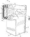
- FIG. 1 there is shown a fluidic cartridge 10 containing a protective sealing tape 12 and a pull tape 14 overlapping a portion 16 of the protective sealing tape 12.
- the protective sealing tape 12 is used to cover a nozzle plate 18 of an ejection head 20 attached to the fluidic cartridge 10.
- the protective sealing tape 12 prevents contamination and damage to the ejection head 20, seals nozzle holes in the nozzle plate 18 so that fluid in the fluidic cartridge 10 does not lead out or dry out and plug the nozzle holes during shipping and storage of the fluidic cartridge 10.
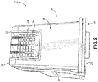
- a flexible circuit 22 is electrically connected to the ejection head 20 to control ejection of fluid from the fluidic cartridge 10 when the fluidic cartridge 10 is in use.
- the flexible circuit has electrical contacts 24 thereon that are disposed on a first end wall 26 of the fluidic cartridge 10 for electrical connection to fluid ejection device, such as a printer, inhaler, E-cigarette, and the like.
- a cover 28 is attached to a first end 30 of the fluidic cartridge 10 opposite a second end 32 of the fluidic cartridge that contains the ejection head 20.
- the pull tape 14 and protective sealing tape 12 are removably attached to a first side wall of the fluidic cartridge ( FIG. 1 ).
- the fluidic cartridge 10 also contains a second side wall 38 opposite the first side wall 34 and a second end wall 40 opposite the first end 30 thereof.
- the pull tape 14 is peeled away from the first side wall 34 of the fluidic cartridge 10 by grasping a tab on one end of the pull tape 14 and pulling the pull tape 14 away from the first side wall 34 of the fluidic cartridge 10.
- the protective sealing tape 12 attached to the pull tape 14 in the overlapping area 16, is also removed from the fluidic cartridge 10 so that fluid can then be ejected from the ejection head 20.
- the ejection head 20 includes a semiconductor substrate 42 to which the flexible circuit 22 is electrically attached and the nozzle plate 18 attached to the semiconductor substrate 42 in a window (not shown) of the flexible circuit 22.
- the fluidic cartridge 10 is filled with an open cell foam material 46 that holds fluid to be ejected from the ejection head 20.
- the protective sealing tape 12 is used to cover and protect nozzle holes on the nozzle plate 18 as described above.
- the protective sealing tape 12 is shown in FIGS. 5 and 6 and is tape 12 having an overall thickness of from about 45 to about 150 microns.
- the protective sealing tape 12 has a base film layer 50 of polyethylene terephthalate, polypropylene, polyethylene, polybutene, polybutadiene, polymethyl pentene, polyvinyl chloride, vinyl chloride copolymer, polybutylene terephthalate, polyurethane, ethylene-vinyl acetate copolymer, ionomer resin, ethylene-(meth)acrylic acid copolymer, ethylene-alkyl meth(acrylate) copolymer, polystyrene, polyimide, polyamide, or polycarbonate having a thickness of from about 20 to about 80 microns such as from about 25 to about 75 microns and an adhesive layer 52 on one side thereof having a thickness of from about 20 to about 70 microns.
- the adhesive layer 52 has a peel strength ranging from about 170 to about 350 Newton per meter (N/m) on a silicon wafer as determined using a 20-millimeter-wide sample at a peeling speed of 300 mm/min and at an angle of 90 degrees. It is important that adhesive layer 52 of the protective sealing tape 12 contain a low amount of impurities since it is in intimate contact with the nozzle plate 18 and could contaminate the nozzle holes in the nozzle plate thereby blocking the nozzle holes from functioning properly.
- the pull tape 14 is attached in the overlap area 16 to a backside 54 of the protective sealing tape 12.
- the pull tape can be made of a wide variety of materials provided the adhesive used on an underside 56 of the pull tape 14 has a peel strength of about 2 times greater and desirably at least about 3 time greater than the peel strength of the protective sealing tape 12. In some embodiments, the pull tape 14 has a peel strength of greater than about 120 N/m, such as greater than about 140 N/m, and desirably greater than about 200 N/m.
- the pull tape 14 is also attached to the first side wall 34 of the cartridge 10 adjacent to the protective sealing tape 12.
- the ejection head 20 with its semiconductor substrate 42 and nozzle plate 18 is a precisely manufactured device that is capable of high resolution fluid ejection. Accordingly, protection of the ejection head 20 is important for the proper operation of the fluid ejection device.
- the protective sealing tape 12 is applied to the ejection head 20 and the first side wall 34 of the fluidic ejection cartridge 10 and the pull tape 14 is applied to the first side wall 34 of the fluidic ejection cartridge 10 adjacent an end of the protective sealing tape 12.
- the protective sealing tape 12 may be peeled from the ejection head 20 in a direction that is orthogonal to a longitudinal direction of the nozzle plate 18 and substrate 42.
- Such peeling direction is effective to reduce stresses that may occur to the ejection head 20 when the protective sealing tape 12 is peeled therefrom and reduces the likelihood that the nozzle plate 18 will delaminate from the substrate 42. Accordingly, it is desirable that the protective sealing tape 12 be peeled in the orthogonal direction rather than in a longitudinal direction with respect to the ejection head.
- the pull tape 14 overlap the backside 54 of the protective sealing tape 12 to improve the removal of the protective sealing tape 12 from the cartridge 10. Also, since the protective sealing tape 12 has a lower peel strength than the pull tape 14, overlapping the protective sealing tape 12 on a backside 58 of the pull tape 14 may lead to separation of the protective sealing tape 12 from the pull tape 14 and thus result in incomplete removal of the protective sealing tape 12 from the ejection head 20.
- the pull tape adhesive may be a pressure sensitive adhesive selected from various radiation curable polymers such as epoxy, diolefin, urethane, polyimide, acrylic, silicone and vinyl ester polymers including a polymerization initiator.
- acrylic polymers which may be used include homopolymers or copolymers of an alkyl(meth)acrylate, and copolymers of (meth)acrylate and another copolymerizable monomer such as a hydroxyalkyl(meth)acrylate, glycidyl(meth)acrylate, (meth)acrylic acid, itaconic acid, maleic anhydride, (meth)acrylic amide, (meth)acrylic N-hydroxymethylamide, an alkylaminoalkyl(meth)acrylate, silicone adducted acrylate, vinyl acetate, styrene or acrylonitrile.
- polyimide and silicone based materials may also be used as base materials for the pressure sensitive adhesive layer on the underside 56 of the pull tape 14.
- silicone-based adhesives were the most resistant to the very harsh solvents used in commercial and industrial ink.
- silicone resins used to make silicone adhesives.
- the most common silicone resin uses a benzoyl peroxide (BPO) catalyst. These resins have excellent high temperature properties, tack and adhesion. Unfortunately, solvents can react with the crosslinking reaction which breaks down the adhesive.
- BPO benzoyl peroxide
- the other type of silicone resin is the platinum-cured silicone.
- the platinum-cured silicone resin is less common because it is more expensive and can be poisoned easily if not properly processed. However, the platinum-cured silicone resin is more resistant to solvent attack. It was observed that the platinum-cured silicone resin adhesive tapes were the only adhesive materials compatible with the solvent based systems. To further improve the cohesive properties of the adhesive, glass fibers were added to the resin.
- a particularly suitable platinum-cured silicone adhesive comprises a glass-filled mixture of vinyl functional polydimethylsiloxane and silicone resin in toluene and xylene.
- a suitable platinum-cured silicone adhesive has an adhesion characteristic ranging from above about 4 g/cm to less than about 300 g/cm, and particularly in the range of from about 40 g/cm to about 250 g/cm and does not dissolve in methylethyl ketone, ethanol or methanol.
- Suitable protective sealing tapes 12 include the platinum-cured silicone-based adhesive for contact and sealing of nozzle holes in the nozzle plate 18.
- the adhesive layer 52 is suitably a glass filled platinum-cured silicone adhesive layer 52.
- Such glass filled platinum-cured silicone adhesive materials have been found to be particularly resistant to organic solvent-based fluids thereby maintaining a peel strength for a prolonged period of time while being exposed to the organic solvent-based fluid in the cartridge 10.
- Conventional adhesives such as acrylic adhesive, peroxide-catalyzed silicone adhesive, natural and synthetic rubber based adhesive, and hot melt adhesives fail to maintain suitable peel strength, and/or fail to remain in place on the nozzle plate despite relatively high initial peel strengths as shown by the following examples.
- a screening test was used to evaluate protective tapes containing different adhesive materials.
- the screening test included placing a sample tape on a semiconductor wafer that was coated with a hydrophobic epoxy nozzle plate material. A peel test tool was then used to determine the initial peel strength (T0) of the sample tape with respect to the coated wafer.
- T0 initial peel strength
- the wafer was removed from the vessel and the solvent was rinsed from the wafer and tape with ethanol.
- the peel tool was used to determine the peel strength (T3) after 3 days in the solvent.
- the sample tape was tested on an actual ejection head of a fluidic cartridge containing an organic solvent-based fluid.
- the sample tape was attached to the ejection head and the cartridge was filled in an organic solvent-based fluid.
- the cartridge was placed in an oven at 60° C for 8 weeks and any leakage of fluid from the ejection head was recorded. Drop and altitude testing was also conducted on the cartridge containing the sample tape. Results of the solvent test of various tapes containing different adhesive materials is shown in the following table. Table 1 Sample No.
- Organic solvents are a very harsh environment for organic materials, especially adhesives.
- the platinum-cured silicone adhesives were found to withstand the harsh environment better than acrylics, rubbers, synthetic rubbers, acrylic/rubber hybrids or hot melt adhesives. As the data shows however, not all silicone adhesives can pass the aggressive testing with a solvent. Only the platinum-cured silicone adhesive tape was found to be suitable for use on fluidic cartridges containing organic solvent-based fluids.
- fluidic ejection cartridges 10 may be used in variety of applications, including for instance inkjet printing applications. Fluidic ejection cartridges may also be used for other nonprinting applications as well, particularly for applications calling for the precise metering of small amounts of liquid materials and vaporous materials.
- the ejection cartridges described herein may be used in the preparation of cosmetics, paints, or lubricants and in the ejection of liquids and vapors for medical treatment.
Landscapes
- Engineering & Computer Science (AREA)
- Manufacturing & Machinery (AREA)
- Ink Jet (AREA)
- Adhesive Tapes (AREA)
- Coating Apparatus (AREA)
- Adhesives Or Adhesive Processes (AREA)
Abstract
Description
- This disclosure relates to the field of fluidic ejection cartridges. More particularly, this disclosure relates to an improved sealing tape for use on fluidic ejection cartridges that contain organic solvents.
- Fluidic ejection cartridges may be used in variety of applications, including for instance inkjet printing applications, medicinal fluid delivery applications, and vapor delivery applications. The amount of time such cartridges remain in transit from the manufacture and/or in storage (prior to installation and use) may constitute a large portion of the lifecycle of the cartridge. In some instances, the shipping and storage time may even constitute the majority of the lifecycle of the cartridge. Consequently, it is important that the operability of the cartridge not degrade during storage, even if the cartridge remains in storage for an extended period of time.
- During shipping and storage of the fluidic ejection cartridges, a protective tape is used to cover the ejection head and ejection nozzles on the ejection head. The protective tape prevents contamination of the ejection head, prevents seepage of fluid from the ejection head, and reduces the amount of solvent evaporated from the fluid in the cartridge during shipping and storage of the cartridge. Prior to use, the protective tape is removed from the fluidic ejection cartridge to expose the ejection nozzles.
- Conventional pressure sensitive adhesive (PSA) sealing tapes that are used to seal the nozzle holes in an ejection head are typically an acrylic type adhesive with a polyvinyl chloride or polyethylene terephthalate backing film. However, when the fluidic cartridge contains an organic solvent rather than an aqueous-based fluid, the acrylic adhesives in conventional protective tapes may be solubilized by the organic solvent causing fluid leaking from the cartridge and/or premature peeling of the tape from the ejection head.
- In order to assure that the protective tape does not prematurely peel off of the ejection head, a suitable tape and adhesive system must be found that will not be readily solubilized by the organic solvents present in the fluidic cartridge, and that provides a protective tape having a suitable peel strength. Accordingly, what is needed is a pressure sensitive adhesive tape sealing system that can be used with fluidic cartridges that contain organic solvents rather than aqueous-based fluids.
- With regard to the foregoing, an embodiment of the disclosure provides a fluidic ejection cartridge and protective tape therefor. The fluidic ejection cartridge has a cartridge body for an organic solvent-based fluid having a cover closing a first end thereof, an ejection head on a second end thereof opposite the first end, and side walls attached to the first and second ends between the first and second ends, wherein the side walls comprise a first side wall, a second side wall opposite the first side wall, a first end wall attached to the first and second side walls, and a second end wall opposite the first end wall attached to the first and second side walls. A removable tape is attached to a nozzle plate of the ejection head and to a portion of the first side wall, wherein the removable tape comprises a polymeric backing film and a platinum-cured silicone adhesive.
- In another aspect, the disclosure provides a method for improving the sealing of a nozzle plate of an ejection head attached to a fluidic ejection cartridge containing an organic solvent-based fluid. The method includes providing a cartridge body for the organic solvent-based fluid having a cover closing a first end thereof, the ejection head on a second end thereof opposite the first end, and side walls attached to the first and second ends between the first and second ends, wherein the side walls comprise a first side wall, a second side wall opposite the first side wall, a first end wall attached to the first and second side walls, and a second end wall opposite the first end wall attached to the first and second side walls. A removable tape is attached to the nozzle plate of the ejection head and to a portion of the first side wall, wherein the removable tape comprises a polymeric backing film and a platinum-cured silicone adhesive.
- In a further aspect, the disclosure provides a removable tape having a peel strength on a dry silicon wafer ranging from about 175 to about 350 N/m. In some embodiments, the removable tape has a peel strength on a silicon wafer immersed in an organic solvent for three days ranging from about 17 to about 70 N/m. In other embodiments, the platinum-cured silicone adhesive has a thickness on the polymeric backing film ranging from about 20 to about 70 microns. In some embodiments, the removable tape includes a platinum-cured silicone adhesive material applied to a polymeric backing film wherein the polymer of the polymeric backing film is selected from polyethylene terephthalate, polypropylene, polyamide and polyimide.
- In some embodiments, the removable tape is disposed on the nozzle plate so as to prevent the organic solvent-based fluid from leaking out of the ejection head.
- In still other embodiments, there is provided a fluidic ejection device that contains a fluidic ejection cartridge for an organic solvent-based fluid wherein a nozzle plate on an ejection head of the fluidic ejection cartridge is covered with a removable tape that contains a polymeric backing film and a platinum-cured silicone adhesive.
- A particular advantage of the embodiments of the disclosure is that the removable tape is effective to cover and seal the nozzle plate of an ejection head for a fluidic cartridge containing an organic solvent-based fluid for an extended period of time during shipping and storage of the fluidic cartridge.
- Further advantages of the disclosure are apparent by reference to the detailed description when considered in conjunction with the figures, which are not to scale so as to more clearly show the details, wherein like reference numbers indicate like elements throughout the several views, and wherein:
-
FIG. 1 is a side perspective view of a fluidic ejection cartridge according to an embodiment of the disclosure. -
FIG. 2 is an end perspective view of the fluidic ejection cartridge ofFIG. 1 . -
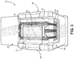
FIG. 3 is a top perspective view of an ejection head for the fluidic ejection cartridge ofFIG. 1 . -
FIG. 4 is a schematic exploded view, not to scale, of the fluidic ejection cartridge ofFIG. 1 . -
FIG. 5 are perspective view, not to scale, of a protective sealing tape and pull tape for protecting the ejection head of the fluidic ejection cartridge ofFIG. 1 . -
FIG. 6 is a cross-sectional view, not to scale, of the protective sealing tape ofFIG. 5 for attaching to a side wall of the fluidic cartridge. - With reference to
FIG. 1 , there is shown afluidic cartridge 10 containing aprotective sealing tape 12 and apull tape 14 overlapping aportion 16 of theprotective sealing tape 12. Theprotective sealing tape 12 is used to cover anozzle plate 18 of anejection head 20 attached to thefluidic cartridge 10. Theprotective sealing tape 12 prevents contamination and damage to theejection head 20, seals nozzle holes in thenozzle plate 18 so that fluid in thefluidic cartridge 10 does not lead out or dry out and plug the nozzle holes during shipping and storage of thefluidic cartridge 10. - As shown in
FIG. 2 , aflexible circuit 22 is electrically connected to theejection head 20 to control ejection of fluid from thefluidic cartridge 10 when thefluidic cartridge 10 is in use. The flexible circuit haselectrical contacts 24 thereon that are disposed on afirst end wall 26 of thefluidic cartridge 10 for electrical connection to fluid ejection device, such as a printer, inhaler, E-cigarette, and the like. Acover 28 is attached to afirst end 30 of thefluidic cartridge 10 opposite asecond end 32 of the fluidic cartridge that contains theejection head 20. Thepull tape 14 andprotective sealing tape 12 are removably attached to a first side wall of the fluidic cartridge (FIG. 1 ). Thefluidic cartridge 10 also contains asecond side wall 38 opposite thefirst side wall 34 and asecond end wall 40 opposite thefirst end 30 thereof. - Before the
cartridge 10 is installed and used in the fluid ejection device, thepull tape 14 is peeled away from thefirst side wall 34 of thefluidic cartridge 10 by grasping a tab on one end of thepull tape 14 and pulling thepull tape 14 away from thefirst side wall 34 of thefluidic cartridge 10. As thepull tape 14 is removed from thefluidic cartridge 10, theprotective sealing tape 12, attached to thepull tape 14 in theoverlapping area 16, is also removed from thefluidic cartridge 10 so that fluid can then be ejected from theejection head 20. - Further details of the
fluidic cartridge 10 may be seen in an exploded view of thefluidic cartridge 10 illustrated schematically inFIG. 4 . Theejection head 20 includes asemiconductor substrate 42 to which theflexible circuit 22 is electrically attached and thenozzle plate 18 attached to thesemiconductor substrate 42 in a window (not shown) of theflexible circuit 22. In some embodiments, thefluidic cartridge 10 is filled with an open cell foam material 46 that holds fluid to be ejected from theejection head 20. - In embodiments described herein, the
protective sealing tape 12 is used to cover and protect nozzle holes on thenozzle plate 18 as described above. Theprotective sealing tape 12 is shown inFIGS. 5 and 6 and istape 12 having an overall thickness of from about 45 to about 150 microns. Theprotective sealing tape 12 has abase film layer 50 of polyethylene terephthalate, polypropylene, polyethylene, polybutene, polybutadiene, polymethyl pentene, polyvinyl chloride, vinyl chloride copolymer, polybutylene terephthalate, polyurethane, ethylene-vinyl acetate copolymer, ionomer resin, ethylene-(meth)acrylic acid copolymer, ethylene-alkyl meth(acrylate) copolymer, polystyrene, polyimide, polyamide, or polycarbonate having a thickness of from about 20 to about 80 microns such as from about 25 to about 75 microns and anadhesive layer 52 on one side thereof having a thickness of from about 20 to about 70 microns. Theadhesive layer 52 has a peel strength ranging from about 170 to about 350 Newton per meter (N/m) on a silicon wafer as determined using a 20-millimeter-wide sample at a peeling speed of 300 mm/min and at an angle of 90 degrees. It is important thatadhesive layer 52 of theprotective sealing tape 12 contain a low amount of impurities since it is in intimate contact with thenozzle plate 18 and could contaminate the nozzle holes in the nozzle plate thereby blocking the nozzle holes from functioning properly. - The
pull tape 14 is attached in theoverlap area 16 to abackside 54 of theprotective sealing tape 12. The pull tape can be made of a wide variety of materials provided the adhesive used on anunderside 56 of thepull tape 14 has a peel strength of about 2 times greater and desirably at least about 3 time greater than the peel strength of theprotective sealing tape 12. In some embodiments, thepull tape 14 has a peel strength of greater than about 120 N/m, such as greater than about 140 N/m, and desirably greater than about 200 N/m. Thepull tape 14 is also attached to thefirst side wall 34 of thecartridge 10 adjacent to theprotective sealing tape 12. - It will be appreciated that the
ejection head 20 with itssemiconductor substrate 42 andnozzle plate 18 is a precisely manufactured device that is capable of high resolution fluid ejection. Accordingly, protection of theejection head 20 is important for the proper operation of the fluid ejection device. As shown inFIG. 1 , theprotective sealing tape 12 is applied to theejection head 20 and thefirst side wall 34 of thefluidic ejection cartridge 10 and thepull tape 14 is applied to thefirst side wall 34 of thefluidic ejection cartridge 10 adjacent an end of theprotective sealing tape 12. Thus, theprotective sealing tape 12 may be peeled from theejection head 20 in a direction that is orthogonal to a longitudinal direction of thenozzle plate 18 andsubstrate 42. Such peeling direction is effective to reduce stresses that may occur to theejection head 20 when theprotective sealing tape 12 is peeled therefrom and reduces the likelihood that thenozzle plate 18 will delaminate from thesubstrate 42. Accordingly, it is desirable that theprotective sealing tape 12 be peeled in the orthogonal direction rather than in a longitudinal direction with respect to the ejection head. - As shown in
FIGs. 1 and5 it is important that thepull tape 14 overlap thebackside 54 of theprotective sealing tape 12 to improve the removal of theprotective sealing tape 12 from thecartridge 10. Also, since theprotective sealing tape 12 has a lower peel strength than thepull tape 14, overlapping theprotective sealing tape 12 on abackside 58 of thepull tape 14 may lead to separation of theprotective sealing tape 12 from thepull tape 14 and thus result in incomplete removal of theprotective sealing tape 12 from theejection head 20. - The adhesive material used on the
underside 56 of thepull tape 14 is not particularly critical to the disclosed embodiments. Accordingly, the pull tape adhesive may be a pressure sensitive adhesive selected from various radiation curable polymers such as epoxy, diolefin, urethane, polyimide, acrylic, silicone and vinyl ester polymers including a polymerization initiator. Examples of acrylic polymers which may be used include homopolymers or copolymers of an alkyl(meth)acrylate, and copolymers of (meth)acrylate and another copolymerizable monomer such as a hydroxyalkyl(meth)acrylate, glycidyl(meth)acrylate, (meth)acrylic acid, itaconic acid, maleic anhydride, (meth)acrylic amide, (meth)acrylic N-hydroxymethylamide, an alkylaminoalkyl(meth)acrylate, silicone adducted acrylate, vinyl acetate, styrene or acrylonitrile. In addition to the acrylic and epoxy adhesive materials, polyimide and silicone based materials may also be used as base materials for the pressure sensitive adhesive layer on theunderside 56 of thepull tape 14. - It is also important that the
adhesive layer 52 of theprotective sealing tape 12 be resistant to organic solvents of the organic solvent-based fluid in thefluidic cartridge 10. Initial studies found that silicone-based adhesives were the most resistant to the very harsh solvents used in commercial and industrial ink. There are 2 types of silicone resins used to make silicone adhesives. The most common silicone resin uses a benzoyl peroxide (BPO) catalyst. These resins have excellent high temperature properties, tack and adhesion. Unfortunately, solvents can react with the crosslinking reaction which breaks down the adhesive. The other type of silicone resin is the platinum-cured silicone. The platinum-cured silicone resin is less common because it is more expensive and can be poisoned easily if not properly processed. However, the platinum-cured silicone resin is more resistant to solvent attack. It was observed that the platinum-cured silicone resin adhesive tapes were the only adhesive materials compatible with the solvent based systems. To further improve the cohesive properties of the adhesive, glass fibers were added to the resin. - A particularly suitable platinum-cured silicone adhesive comprises a glass-filled mixture of vinyl functional polydimethylsiloxane and silicone resin in toluene and xylene. A suitable platinum-cured silicone adhesive has an adhesion characteristic ranging from above about 4 g/cm to less than about 300 g/cm, and particularly in the range of from about 40 g/cm to about 250 g/cm and does not dissolve in methylethyl ketone, ethanol or methanol.
- Accordingly, it was found, quite surprisingly, that only the glass-filled platinum-cured silicone adhesive was effective for use for sealing
cartridges 10 containing organic solvent-based fluids. Suitableprotective sealing tapes 12 include the platinum-cured silicone-based adhesive for contact and sealing of nozzle holes in thenozzle plate 18. In particular, theadhesive layer 52 is suitably a glass filled platinum-curedsilicone adhesive layer 52. Such glass filled platinum-cured silicone adhesive materials have been found to be particularly resistant to organic solvent-based fluids thereby maintaining a peel strength for a prolonged period of time while being exposed to the organic solvent-based fluid in thecartridge 10. Conventional adhesives, such as acrylic adhesive, peroxide-catalyzed silicone adhesive, natural and synthetic rubber based adhesive, and hot melt adhesives fail to maintain suitable peel strength, and/or fail to remain in place on the nozzle plate despite relatively high initial peel strengths as shown by the following examples. - In order to demonstrate the advantages of the embodiments of the disclosure, the following non-limiting example is provided.
- In order to determine if a particular adhesive material was suitable for use on a fluidic cartridge containing an organic solvent-based fluid, a screening test was used to evaluate protective tapes containing different adhesive materials. The screening test included placing a sample tape on a semiconductor wafer that was coated with a hydrophobic epoxy nozzle plate material. A peel test tool was then used to determine the initial peel strength (T0) of the sample tape with respect to the coated wafer. Next the wafer with the sample tape attached was placed in a vessel containing an organic solvent for 3 days and the solvent was maintained at a temperature of 60° C.
- After 3 days, the wafer was removed from the vessel and the solvent was rinsed from the wafer and tape with ethanol. The peel tool was used to determine the peel strength (T3) after 3 days in the solvent.
- If the peel strength of the sample tape was sufficient to hold the sample tape on the wafer, then the sample tape was tested on an actual ejection head of a fluidic cartridge containing an organic solvent-based fluid. In the ejection head test, the sample tape was attached to the ejection head and the cartridge was filled in an organic solvent-based fluid. The cartridge was placed in an oven at 60° C for 8 weeks and any leakage of fluid from the ejection head was recorded. Drop and altitude testing was also conducted on the cartridge containing the sample tape. Results of the solvent test of various tapes containing different adhesive materials is shown in the following table.
Table 1 Sample No. Description Adhesive Type T0 day Peel Strength (N/m) T3 days Peel strength (N/m) Does the Sealing Tape Seal a fluidic cartridge 1 Acrylic 1 Acrylic 131-210 Fell off No 2 Acrylic 2 Acrylic 8-18 Fell off No 3 Acrylic 3 Acrylic 420-683 Fell off No. 4 Silicone 1 Silicone 56-175 2.3-7 No 5 Silicone 2 Non-glass filled Peroxide-cured Silicone 297 26 No 6 Silicone 3 Silicone 427-595 11 or Messy, pulled off backing film or fell off No 7 Hot melt 1 Ethylene acrylic acid copolymer 88 Fell off No 8 Hot melt 2 Polyester thermoplastic 0 Fell off No 9 Hot melt 3 Nitrile Phenolic 82.5 Fell off No 10 Rubber 1 Synthetic 560-1366 Fell off No 11 Rubber 2 Rubber 237-876 Fell off No 12 Rubber 3 Acrylic/rubber hybrid 508 Fell off No 13 Silicone 4 Glass-filled Platinum-cured 263 35 Yes - As shown by the above data, acrylic adhesive samples 1 and 3, silicone adhesive samples 5, 6 and 13, and
rubber samples - Organic solvents are a very harsh environment for organic materials, especially adhesives. The platinum-cured silicone adhesives were found to withstand the harsh environment better than acrylics, rubbers, synthetic rubbers, acrylic/rubber hybrids or hot melt adhesives. As the data shows however, not all silicone adhesives can pass the aggressive testing with a solvent. Only the platinum-cured silicone adhesive tape was found to be suitable for use on fluidic cartridges containing organic solvent-based fluids.
- As noted above,
fluidic ejection cartridges 10 may be used in variety of applications, including for instance inkjet printing applications. Fluidic ejection cartridges may also be used for other nonprinting applications as well, particularly for applications calling for the precise metering of small amounts of liquid materials and vaporous materials. For example, the ejection cartridges described herein may be used in the preparation of cosmetics, paints, or lubricants and in the ejection of liquids and vapors for medical treatment.
Claims (13)
- A fluidic ejection cartridge (10), comprising:a cartridge body for an organic solvent-based fluid having a cover (28) closing a first end (30) thereof, an ejection head (20) on a second end (32) thereof opposite to the first end (30), and side walls (34, 38) attached to the first and second ends (30, 32) between the first and second ends (30, 32), wherein the side walls (34, 38) comprise a first side wall (34), a second side wall (38) opposite to the first side wall (34), a first end wall (26) attached to the first and second side walls (30, 32), and a second end wall (40) opposite to the first end wall (26) attached to the first and second side walls (30, 32); anda removable tape (12) attached to a nozzle plate (18) of the ejection head (20) and to a portion of the first side wall (34), wherein the removable tape (12) comprises a polymeric backing film and a platinum-cured silicone adhesive.
- The fluidic ejection cartridge of claim 1, wherein the removable tape (12) has a peel strength on a dry silicon wafer ranging from about 175 to about 350 N/m.
- The fluidic ejection cartridge of claim 1 or 2, wherein the removable tape (12) has a peel strength on a silicon wafer immersed in an organic solvent for three days ranging from about 17 to about 70 N/m.
- The fluidic ejection cartridge of any one of claims 1 to 3, wherein the removable tape (12) is disposed on the nozzle plate (18) so as to prevent the organic solvent-based fluid from leaking out of the ejection head (20).
- The fluidic ejection cartridge of any one of claims 1 to 4, wherein the platinum-cured silicone adhesive has a thickness on the polymeric backing film ranging from about 25 to about 75 microns.
- The fluidic ejection cartridge of any one of claims 1 to 5, wherein the removable tape (12) comprises a glass-filled, platinum-cured silicone adhesive material applied to the polymeric backing film wherein a polymer of the polymeric backing film is selected from a group consisting of polyethylene terephthalate, polypropylene, polyamide and polyimide.
- A fluidic ejection device comprising the fluidic ejection cartridge of any one of claims 1 to 6.
- A method for improving the sealing of a nozzle plate (18) of an ejection head (20) attached to a fluidic ejection cartridge (10) containing an organic solvent-based fluid, the method comprising:providing a cartridge body for the organic solvent-based fluid having a cover (28) closing a first end (30) thereof, the ejection head (30) on a second end (32) thereof opposite to the first end (30), and side walls (34, 38) attached to the first and second ends (30, 32) between the first and second ends (30, 32), wherein the side walls (34, 38) comprise a first side wall (34), a second side wall (38) opposite to the first side wall(34), a first end wall (26) attached to the first and second side walls (30, 32), and a second end wall (40) opposite to the first end wall (26) attached to the first and second side walls (30, 32); andattaching a removable tape (12) to the nozzle plate (18) of the ejection head (20) and to a portion of the first side wall (34), wherein the removable tape (12) comprises a polymeric backing film and a platinum-cured silicone adhesive.
- The method of claim 8, wherein the removable tape (12) has a peel strength on a dry silicon wafer ranging from about 175 to about 350 N/m.
- The method of claim 8 or 9, wherein the removable tape (12) has a peel strength on a silicon wafer immersed in an organic solvent for three days ranging from about 17 to about 70 N/m.
- The method of any one of claims 8 to 10, wherein the removable tape (12) covers the nozzle plate (18) on the ejection head (20) and prevents the organic solvent-based fluid from leaking out of the ejection head (20).
- The method of any one of claims 8 to 11, wherein the platinum-cured silicone adhesive has a thickness on the polymeric backing film ranging from about 25 to about 75 microns.
- The method of any one of claims 8 to 12, wherein the removable tape (12) comprises a glass-filled, platinum-cured silicone adhesive material applied to a polymeric backing film wherein a polymer of the polymeric backing film is selected from a group consisting of polyethylene terephthalate, polypropylene, polyamide and polyimide.
Applications Claiming Priority (1)
| Application Number | Priority Date | Filing Date | Title |
|---|---|---|---|
| US16/741,812 US10987935B1 (en) | 2020-01-14 | 2020-01-14 | Organic solvent sealing tape |
Publications (2)
| Publication Number | Publication Date |
|---|---|
| EP3851285A1 true EP3851285A1 (en) | 2021-07-21 |
| EP3851285B1 EP3851285B1 (en) | 2023-01-04 |
Family
ID=74003690
Family Applications (1)
| Application Number | Title | Priority Date | Filing Date |
|---|---|---|---|
| EP20217477.7A Active EP3851285B1 (en) | 2020-01-14 | 2020-12-29 | Sealing tape for organic solvent-based fluidic cartridges and method for improving the sealing of a nozzle plate |
Country Status (4)
| Country | Link |
|---|---|
| US (1) | US10987935B1 (en) |
| EP (1) | EP3851285B1 (en) |
| JP (1) | JP2021109447A (en) |
| CN (2) | CN115230321B (en) |
Families Citing this family (2)
| Publication number | Priority date | Publication date | Assignee | Title |
|---|---|---|---|---|
| US12023935B2 (en) * | 2022-08-10 | 2024-07-02 | Funai Electric Co., Ltd. | Nozzle sealing tape |
| US20250121601A1 (en) * | 2023-10-02 | 2025-04-17 | Funai Electric Co., Ltd. | Silcone tape having improved adhesive properties |
Citations (6)
| Publication number | Priority date | Publication date | Assignee | Title |
|---|---|---|---|---|
| JPH0584925A (en) * | 1991-09-26 | 1993-04-06 | Canon Inc | Adhesive tape and recording head |
| US6012807A (en) * | 1998-03-06 | 2000-01-11 | Hewlett-Packard Company | Ink containment unit for use in an ink delivery system |
| US20020140763A1 (en) * | 2001-03-28 | 2002-10-03 | Nelson Veronica A. | Hot-melt seal for nozzles on print cartridges and method |
| KR20060035820A (en) * | 2004-10-20 | 2006-04-27 | 삼성전자주식회사 | Inkjet Cartridge and Manufacturing Method Thereof |
| US20120098885A1 (en) * | 2010-10-22 | 2012-04-26 | Canon Kabushiki Kaisha | Seal tape for ink jet recording head, and ink jet recording head |
| JP2017014308A (en) * | 2015-06-26 | 2017-01-19 | Dic株式会社 | Adhesive tape, protective member and electronic equipment |
Family Cites Families (13)
| Publication number | Priority date | Publication date | Assignee | Title |
|---|---|---|---|---|
| EP0456840B1 (en) | 1989-12-06 | 2001-03-14 | Canon Kabushiki Kaisha | Pressure-sensitive adhesive tape, ink jet recording head, and storing method |
| US6634732B2 (en) * | 2001-09-11 | 2003-10-21 | Hewlett-Packard Development Company, L.P. | Thermoplastic polymer film sealing of nozzles on fluid ejection devices and method |
| US7540584B2 (en) | 2005-03-31 | 2009-06-02 | Lexmark International, Inc. | Orifice plate protection device |
| JP4702937B2 (en) * | 2005-07-08 | 2011-06-15 | キヤノン株式会社 | Inkjet recording head |
| US8157347B2 (en) * | 2005-07-08 | 2012-04-17 | Canon Kabushiki Kaisha | Ink jet recording head and ink jet recording head cartridge |
| KR101054974B1 (en) * | 2006-04-24 | 2011-08-05 | 캐논 가부시끼가이샤 | Ink jet recording head, ink jet cartridge, and ink jet recording head manufacturing method |
| JP5063452B2 (en) * | 2007-04-13 | 2012-10-31 | キヤノン株式会社 | Inkjet head |
| US20090155596A1 (en) | 2007-12-12 | 2009-06-18 | 3M Innovative Properties Company | Nozzle sealing composition and method |
| US8256872B2 (en) * | 2010-05-19 | 2012-09-04 | Phoenix Ink Corporation | Inkjet cartridge printhead sealing band |
| US9132654B1 (en) * | 2014-07-08 | 2015-09-15 | Funai Electric Co., Ltd. | Label for inkjet printhead |
| US9878554B1 (en) | 2016-10-13 | 2018-01-30 | Funai Electric Co., Ltd. | Packaging system for fluidic ejection cartridge with controlled protective tape removal |
| US10384458B1 (en) * | 2018-05-08 | 2019-08-20 | Funai Electric Co., Ltd. | Fluidic ejection cartridge for improved protective tape removal |
| US10814638B2 (en) * | 2018-05-08 | 2020-10-27 | Funai Electric Co. Ltd | Fluidic ejection cartridge for improved protective tape removal |
-
2020
- 2020-01-14 US US16/741,812 patent/US10987935B1/en active Active
- 2020-12-29 EP EP20217477.7A patent/EP3851285B1/en active Active
-
2021
- 2021-01-04 CN CN202210906907.9A patent/CN115230321B/en active Active
- 2021-01-04 CN CN202110003623.4A patent/CN113119594B/en active Active
- 2021-01-07 JP JP2021001632A patent/JP2021109447A/en active Pending
Patent Citations (6)
| Publication number | Priority date | Publication date | Assignee | Title |
|---|---|---|---|---|
| JPH0584925A (en) * | 1991-09-26 | 1993-04-06 | Canon Inc | Adhesive tape and recording head |
| US6012807A (en) * | 1998-03-06 | 2000-01-11 | Hewlett-Packard Company | Ink containment unit for use in an ink delivery system |
| US20020140763A1 (en) * | 2001-03-28 | 2002-10-03 | Nelson Veronica A. | Hot-melt seal for nozzles on print cartridges and method |
| KR20060035820A (en) * | 2004-10-20 | 2006-04-27 | 삼성전자주식회사 | Inkjet Cartridge and Manufacturing Method Thereof |
| US20120098885A1 (en) * | 2010-10-22 | 2012-04-26 | Canon Kabushiki Kaisha | Seal tape for ink jet recording head, and ink jet recording head |
| JP2017014308A (en) * | 2015-06-26 | 2017-01-19 | Dic株式会社 | Adhesive tape, protective member and electronic equipment |
Also Published As
| Publication number | Publication date |
|---|---|
| CN113119594A (en) | 2021-07-16 |
| EP3851285B1 (en) | 2023-01-04 |
| CN115230321B (en) | 2024-05-03 |
| JP2021109447A (en) | 2021-08-02 |
| CN113119594B (en) | 2022-08-23 |
| CN115230321A (en) | 2022-10-25 |
| US10987935B1 (en) | 2021-04-27 |
Similar Documents
| Publication | Publication Date | Title |
|---|---|---|
| CA2459988C (en) | Thermoplastic polymer film sealing of nozzles on fluid ejection devices and method | |
| EP3851285B1 (en) | Sealing tape for organic solvent-based fluidic cartridges and method for improving the sealing of a nozzle plate | |
| KR101979956B1 (en) | Pressure-sensitive adhesive tape for battery and battery using the pressure-sensitive adhesive tape | |
| KR101574373B1 (en) | Adhesive sheet | |
| EP0456840B1 (en) | Pressure-sensitive adhesive tape, ink jet recording head, and storing method | |
| AU2002330014A1 (en) | Thermoplastic polymer film sealing of nozzles on fluid ejection devices and method | |
| JPH0577436A (en) | Inkjet recording head and storage method | |
| KR101492371B1 (en) | Heat-peelable pressure-sensitive adhesive tape and cutting method of electronic components | |
| KR101602611B1 (en) | Method of manufacturing electrochemical device and electrochemical device | |
| JP5226232B2 (en) | Adhesive sheet | |
| US7540584B2 (en) | Orifice plate protection device | |
| EP3566874B1 (en) | Fluidic ejection cartridge and fluid ejection device thereof | |
| JP2004082728A (en) | Release sheet and adhesive | |
| US11433681B2 (en) | Sealing tape for organic solvent-based fluidic cartridges | |
| JP2015193688A (en) | Agent treatment protection sheet | |
| US8157347B2 (en) | Ink jet recording head and ink jet recording head cartridge | |
| US10814638B2 (en) | Fluidic ejection cartridge for improved protective tape removal | |
| US20250121601A1 (en) | Silcone tape having improved adhesive properties | |
| CN120019129A (en) | Adhesive with pressure regulation | |
| JP3034030B2 (en) | Adhesive tape, inkjet recording head, and storage method | |
| JPWO1991008267A1 (en) | Adhesive tape, inkjet recording head, and storage method |
Legal Events
| Date | Code | Title | Description |
|---|---|---|---|
| PUAI | Public reference made under article 153(3) epc to a published international application that has entered the european phase |
Free format text: ORIGINAL CODE: 0009012 |
|
| STAA | Information on the status of an ep patent application or granted ep patent |
Free format text: STATUS: THE APPLICATION HAS BEEN PUBLISHED |
|
| AK | Designated contracting states |
Kind code of ref document: A1 Designated state(s): AL AT BE BG CH CY CZ DE DK EE ES FI FR GB GR HR HU IE IS IT LI LT LU LV MC MK MT NL NO PL PT RO RS SE SI SK SM TR |
|
| STAA | Information on the status of an ep patent application or granted ep patent |
Free format text: STATUS: REQUEST FOR EXAMINATION WAS MADE |
|
| 17P | Request for examination filed |
Effective date: 20210917 |
|
| RBV | Designated contracting states (corrected) |
Designated state(s): AL AT BE BG CH CY CZ DE DK EE ES FI FR GB GR HR HU IE IS IT LI LT LU LV MC MK MT NL NO PL PT RO RS SE SI SK SM TR |
|
| GRAP | Despatch of communication of intention to grant a patent |
Free format text: ORIGINAL CODE: EPIDOSNIGR1 |
|
| STAA | Information on the status of an ep patent application or granted ep patent |
Free format text: STATUS: GRANT OF PATENT IS INTENDED |
|
| GRAS | Grant fee paid |
Free format text: ORIGINAL CODE: EPIDOSNIGR3 |
|
| INTG | Intention to grant announced |
Effective date: 20221028 |
|
| GRAA | (expected) grant |
Free format text: ORIGINAL CODE: 0009210 |
|
| STAA | Information on the status of an ep patent application or granted ep patent |
Free format text: STATUS: THE PATENT HAS BEEN GRANTED |
|
| AK | Designated contracting states |
Kind code of ref document: B1 Designated state(s): AL AT BE BG CH CY CZ DE DK EE ES FI FR GB GR HR HU IE IS IT LI LT LU LV MC MK MT NL NO PL PT RO RS SE SI SK SM TR |
|
| REG | Reference to a national code |
Ref country code: GB Ref legal event code: FG4D |
|
| REG | Reference to a national code |
Ref country code: DE Ref legal event code: R096 Ref document number: 602020007360 Country of ref document: DE |
|
| REG | Reference to a national code |
Ref country code: CH Ref legal event code: EP |
|
| REG | Reference to a national code |
Ref country code: AT Ref legal event code: REF Ref document number: 1541666 Country of ref document: AT Kind code of ref document: T Effective date: 20230115 |
|
| REG | Reference to a national code |
Ref country code: IE Ref legal event code: FG4D |
|
| REG | Reference to a national code |
Ref country code: LT Ref legal event code: MG9D |
|
| REG | Reference to a national code |
Ref country code: NL Ref legal event code: MP Effective date: 20230104 |
|
| REG | Reference to a national code |
Ref country code: AT Ref legal event code: MK05 Ref document number: 1541666 Country of ref document: AT Kind code of ref document: T Effective date: 20230104 |
|
| PG25 | Lapsed in a contracting state [announced via postgrant information from national office to epo] |
Ref country code: NL Free format text: LAPSE BECAUSE OF FAILURE TO SUBMIT A TRANSLATION OF THE DESCRIPTION OR TO PAY THE FEE WITHIN THE PRESCRIBED TIME-LIMIT Effective date: 20230104 |
|
| PG25 | Lapsed in a contracting state [announced via postgrant information from national office to epo] |
Ref country code: RS Free format text: LAPSE BECAUSE OF FAILURE TO SUBMIT A TRANSLATION OF THE DESCRIPTION OR TO PAY THE FEE WITHIN THE PRESCRIBED TIME-LIMIT Effective date: 20230104 Ref country code: PT Free format text: LAPSE BECAUSE OF FAILURE TO SUBMIT A TRANSLATION OF THE DESCRIPTION OR TO PAY THE FEE WITHIN THE PRESCRIBED TIME-LIMIT Effective date: 20230504 Ref country code: NO Free format text: LAPSE BECAUSE OF FAILURE TO SUBMIT A TRANSLATION OF THE DESCRIPTION OR TO PAY THE FEE WITHIN THE PRESCRIBED TIME-LIMIT Effective date: 20230404 Ref country code: LV Free format text: LAPSE BECAUSE OF FAILURE TO SUBMIT A TRANSLATION OF THE DESCRIPTION OR TO PAY THE FEE WITHIN THE PRESCRIBED TIME-LIMIT Effective date: 20230104 Ref country code: LT Free format text: LAPSE BECAUSE OF FAILURE TO SUBMIT A TRANSLATION OF THE DESCRIPTION OR TO PAY THE FEE WITHIN THE PRESCRIBED TIME-LIMIT Effective date: 20230104 Ref country code: HR Free format text: LAPSE BECAUSE OF FAILURE TO SUBMIT A TRANSLATION OF THE DESCRIPTION OR TO PAY THE FEE WITHIN THE PRESCRIBED TIME-LIMIT Effective date: 20230104 Ref country code: ES Free format text: LAPSE BECAUSE OF FAILURE TO SUBMIT A TRANSLATION OF THE DESCRIPTION OR TO PAY THE FEE WITHIN THE PRESCRIBED TIME-LIMIT Effective date: 20230104 Ref country code: AT Free format text: LAPSE BECAUSE OF FAILURE TO SUBMIT A TRANSLATION OF THE DESCRIPTION OR TO PAY THE FEE WITHIN THE PRESCRIBED TIME-LIMIT Effective date: 20230104 |
|
| PG25 | Lapsed in a contracting state [announced via postgrant information from national office to epo] |
Ref country code: SE Free format text: LAPSE BECAUSE OF FAILURE TO SUBMIT A TRANSLATION OF THE DESCRIPTION OR TO PAY THE FEE WITHIN THE PRESCRIBED TIME-LIMIT Effective date: 20230104 Ref country code: PL Free format text: LAPSE BECAUSE OF FAILURE TO SUBMIT A TRANSLATION OF THE DESCRIPTION OR TO PAY THE FEE WITHIN THE PRESCRIBED TIME-LIMIT Effective date: 20230104 Ref country code: IS Free format text: LAPSE BECAUSE OF FAILURE TO SUBMIT A TRANSLATION OF THE DESCRIPTION OR TO PAY THE FEE WITHIN THE PRESCRIBED TIME-LIMIT Effective date: 20230504 Ref country code: GR Free format text: LAPSE BECAUSE OF FAILURE TO SUBMIT A TRANSLATION OF THE DESCRIPTION OR TO PAY THE FEE WITHIN THE PRESCRIBED TIME-LIMIT Effective date: 20230405 Ref country code: FI Free format text: LAPSE BECAUSE OF FAILURE TO SUBMIT A TRANSLATION OF THE DESCRIPTION OR TO PAY THE FEE WITHIN THE PRESCRIBED TIME-LIMIT Effective date: 20230104 |
|
| REG | Reference to a national code |
Ref country code: DE Ref legal event code: R097 Ref document number: 602020007360 Country of ref document: DE |
|
| PG25 | Lapsed in a contracting state [announced via postgrant information from national office to epo] |
Ref country code: SM Free format text: LAPSE BECAUSE OF FAILURE TO SUBMIT A TRANSLATION OF THE DESCRIPTION OR TO PAY THE FEE WITHIN THE PRESCRIBED TIME-LIMIT Effective date: 20230104 Ref country code: RO Free format text: LAPSE BECAUSE OF FAILURE TO SUBMIT A TRANSLATION OF THE DESCRIPTION OR TO PAY THE FEE WITHIN THE PRESCRIBED TIME-LIMIT Effective date: 20230104 Ref country code: EE Free format text: LAPSE BECAUSE OF FAILURE TO SUBMIT A TRANSLATION OF THE DESCRIPTION OR TO PAY THE FEE WITHIN THE PRESCRIBED TIME-LIMIT Effective date: 20230104 Ref country code: DK Free format text: LAPSE BECAUSE OF FAILURE TO SUBMIT A TRANSLATION OF THE DESCRIPTION OR TO PAY THE FEE WITHIN THE PRESCRIBED TIME-LIMIT Effective date: 20230104 Ref country code: CZ Free format text: LAPSE BECAUSE OF FAILURE TO SUBMIT A TRANSLATION OF THE DESCRIPTION OR TO PAY THE FEE WITHIN THE PRESCRIBED TIME-LIMIT Effective date: 20230104 |
|
| PLBE | No opposition filed within time limit |
Free format text: ORIGINAL CODE: 0009261 |
|
| STAA | Information on the status of an ep patent application or granted ep patent |
Free format text: STATUS: NO OPPOSITION FILED WITHIN TIME LIMIT |
|
| PG25 | Lapsed in a contracting state [announced via postgrant information from national office to epo] |
Ref country code: SK Free format text: LAPSE BECAUSE OF FAILURE TO SUBMIT A TRANSLATION OF THE DESCRIPTION OR TO PAY THE FEE WITHIN THE PRESCRIBED TIME-LIMIT Effective date: 20230104 |
|
| 26N | No opposition filed |
Effective date: 20231005 |
|
| PG25 | Lapsed in a contracting state [announced via postgrant information from national office to epo] |
Ref country code: SI Free format text: LAPSE BECAUSE OF FAILURE TO SUBMIT A TRANSLATION OF THE DESCRIPTION OR TO PAY THE FEE WITHIN THE PRESCRIBED TIME-LIMIT Effective date: 20230104 |
|
| PG25 | Lapsed in a contracting state [announced via postgrant information from national office to epo] |
Ref country code: IT Free format text: LAPSE BECAUSE OF FAILURE TO SUBMIT A TRANSLATION OF THE DESCRIPTION OR TO PAY THE FEE WITHIN THE PRESCRIBED TIME-LIMIT Effective date: 20230104 |
|
| REG | Reference to a national code |
Ref country code: CH Ref legal event code: PL |
|
| PG25 | Lapsed in a contracting state [announced via postgrant information from national office to epo] |
Ref country code: LU Free format text: LAPSE BECAUSE OF NON-PAYMENT OF DUE FEES Effective date: 20231229 |
|
| PG25 | Lapsed in a contracting state [announced via postgrant information from national office to epo] |
Ref country code: MC Free format text: LAPSE BECAUSE OF FAILURE TO SUBMIT A TRANSLATION OF THE DESCRIPTION OR TO PAY THE FEE WITHIN THE PRESCRIBED TIME-LIMIT Effective date: 20230104 |
|
| REG | Reference to a national code |
Ref country code: BE Ref legal event code: MM Effective date: 20231231 |
|
| PG25 | Lapsed in a contracting state [announced via postgrant information from national office to epo] |
Ref country code: MC Free format text: LAPSE BECAUSE OF FAILURE TO SUBMIT A TRANSLATION OF THE DESCRIPTION OR TO PAY THE FEE WITHIN THE PRESCRIBED TIME-LIMIT Effective date: 20230104 Ref country code: LU Free format text: LAPSE BECAUSE OF NON-PAYMENT OF DUE FEES Effective date: 20231229 |
|
| REG | Reference to a national code |
Ref country code: IE Ref legal event code: MM4A |
|
| PG25 | Lapsed in a contracting state [announced via postgrant information from national office to epo] |
Ref country code: IE Free format text: LAPSE BECAUSE OF NON-PAYMENT OF DUE FEES Effective date: 20231229 |
|
| PG25 | Lapsed in a contracting state [announced via postgrant information from national office to epo] |
Ref country code: BE Free format text: LAPSE BECAUSE OF NON-PAYMENT OF DUE FEES Effective date: 20231231 |
|
| PG25 | Lapsed in a contracting state [announced via postgrant information from national office to epo] |
Ref country code: FR Free format text: LAPSE BECAUSE OF NON-PAYMENT OF DUE FEES Effective date: 20231231 |
|
| PG25 | Lapsed in a contracting state [announced via postgrant information from national office to epo] |
Ref country code: CH Free format text: LAPSE BECAUSE OF NON-PAYMENT OF DUE FEES Effective date: 20231231 |
|
| PG25 | Lapsed in a contracting state [announced via postgrant information from national office to epo] |
Ref country code: IE Free format text: LAPSE BECAUSE OF NON-PAYMENT OF DUE FEES Effective date: 20231229 Ref country code: FR Free format text: LAPSE BECAUSE OF NON-PAYMENT OF DUE FEES Effective date: 20231231 Ref country code: CH Free format text: LAPSE BECAUSE OF NON-PAYMENT OF DUE FEES Effective date: 20231231 Ref country code: BE Free format text: LAPSE BECAUSE OF NON-PAYMENT OF DUE FEES Effective date: 20231231 |
|
| PG25 | Lapsed in a contracting state [announced via postgrant information from national office to epo] |
Ref country code: BG Free format text: LAPSE BECAUSE OF FAILURE TO SUBMIT A TRANSLATION OF THE DESCRIPTION OR TO PAY THE FEE WITHIN THE PRESCRIBED TIME-LIMIT Effective date: 20230104 |
|
| PG25 | Lapsed in a contracting state [announced via postgrant information from national office to epo] |
Ref country code: BG Free format text: LAPSE BECAUSE OF FAILURE TO SUBMIT A TRANSLATION OF THE DESCRIPTION OR TO PAY THE FEE WITHIN THE PRESCRIBED TIME-LIMIT Effective date: 20230104 |
|
| REG | Reference to a national code |
Ref country code: GB Ref legal event code: 732E Free format text: REGISTERED BETWEEN 20250529 AND 20250604 |
|
| REG | Reference to a national code |
Ref country code: DE Ref legal event code: R081 Ref document number: 602020007360 Country of ref document: DE Owner name: BRADY WORLDWIDE, INC., MILWAUKEE, US Free format text: FORMER OWNER: FUNAI ELECTRIC CO., LTD., DAITO, OSAKA, JP Ref country code: DE Ref legal event code: R082 Ref document number: 602020007360 Country of ref document: DE Representative=s name: BOULT WADE TENNANT LLP, DE |
|
| PG25 | Lapsed in a contracting state [announced via postgrant information from national office to epo] |
Ref country code: CY Free format text: LAPSE BECAUSE OF FAILURE TO SUBMIT A TRANSLATION OF THE DESCRIPTION OR TO PAY THE FEE WITHIN THE PRESCRIBED TIME-LIMIT; INVALID AB INITIO Effective date: 20201229 |
|
| PG25 | Lapsed in a contracting state [announced via postgrant information from national office to epo] |
Ref country code: HU Free format text: LAPSE BECAUSE OF FAILURE TO SUBMIT A TRANSLATION OF THE DESCRIPTION OR TO PAY THE FEE WITHIN THE PRESCRIBED TIME-LIMIT; INVALID AB INITIO Effective date: 20201229 |
|
| PG25 | Lapsed in a contracting state [announced via postgrant information from national office to epo] |
Ref country code: TR Free format text: LAPSE BECAUSE OF FAILURE TO SUBMIT A TRANSLATION OF THE DESCRIPTION OR TO PAY THE FEE WITHIN THE PRESCRIBED TIME-LIMIT Effective date: 20230104 |
|
| PGFP | Annual fee paid to national office [announced via postgrant information from national office to epo] |
Ref country code: GB Payment date: 20251223 Year of fee payment: 6 |
|
| PGFP | Annual fee paid to national office [announced via postgrant information from national office to epo] |
Ref country code: DE Payment date: 20251229 Year of fee payment: 6 |