EP3851255A1 - Robot system, robot system control device, robot system control method, imaging device, control program, and recording medium - Google Patents
Robot system, robot system control device, robot system control method, imaging device, control program, and recording medium Download PDFInfo
- Publication number
- EP3851255A1 EP3851255A1 EP19860262.5A EP19860262A EP3851255A1 EP 3851255 A1 EP3851255 A1 EP 3851255A1 EP 19860262 A EP19860262 A EP 19860262A EP 3851255 A1 EP3851255 A1 EP 3851255A1
- Authority
- EP
- European Patent Office
- Prior art keywords
- imaging
- robot
- control
- imaging apparatus
- robot apparatus
- Prior art date
- Legal status (The legal status is an assumption and is not a legal conclusion. Google has not performed a legal analysis and makes no representation as to the accuracy of the status listed.)
- Pending
Links
Images







Classifications
-
- B—PERFORMING OPERATIONS; TRANSPORTING
- B25—HAND TOOLS; PORTABLE POWER-DRIVEN TOOLS; MANIPULATORS
- B25J—MANIPULATORS; CHAMBERS PROVIDED WITH MANIPULATION DEVICES
- B25J9/00—Program-controlled manipulators
- B25J9/16—Program controls
- B25J9/1694—Program controls characterised by use of sensors other than normal servo-feedback from position, speed or acceleration sensors, perception control, multi-sensor controlled systems, sensor fusion
- B25J9/1697—Vision controlled systems
-
- B—PERFORMING OPERATIONS; TRANSPORTING
- B25—HAND TOOLS; PORTABLE POWER-DRIVEN TOOLS; MANIPULATORS
- B25J—MANIPULATORS; CHAMBERS PROVIDED WITH MANIPULATION DEVICES
- B25J13/00—Controls for manipulators
- B25J13/006—Controls for manipulators by means of a wireless system for controlling one or several manipulators
-
- B—PERFORMING OPERATIONS; TRANSPORTING
- B25—HAND TOOLS; PORTABLE POWER-DRIVEN TOOLS; MANIPULATORS
- B25J—MANIPULATORS; CHAMBERS PROVIDED WITH MANIPULATION DEVICES
- B25J13/00—Controls for manipulators
- B25J13/08—Controls for manipulators by means of sensing devices, e.g. viewing or touching devices
- B25J13/088—Controls for manipulators by means of sensing devices, e.g. viewing or touching devices with position, velocity or acceleration sensors
-
- B—PERFORMING OPERATIONS; TRANSPORTING
- B25—HAND TOOLS; PORTABLE POWER-DRIVEN TOOLS; MANIPULATORS
- B25J—MANIPULATORS; CHAMBERS PROVIDED WITH MANIPULATION DEVICES
- B25J9/00—Program-controlled manipulators
- B25J9/16—Program controls
- B25J9/1602—Program controls characterised by the control system, structure, architecture
- B25J9/161—Hardware, e.g. neural networks, fuzzy logic, interfaces, processor
-
- B—PERFORMING OPERATIONS; TRANSPORTING
- B25—HAND TOOLS; PORTABLE POWER-DRIVEN TOOLS; MANIPULATORS
- B25J—MANIPULATORS; CHAMBERS PROVIDED WITH MANIPULATION DEVICES
- B25J9/00—Program-controlled manipulators
- B25J9/16—Program controls
- B25J9/1656—Program controls characterised by programming, planning systems for manipulators
- B25J9/1664—Program controls characterised by programming, planning systems for manipulators characterised by motion, path, trajectory planning
-
- B—PERFORMING OPERATIONS; TRANSPORTING
- B25—HAND TOOLS; PORTABLE POWER-DRIVEN TOOLS; MANIPULATORS
- B25J—MANIPULATORS; CHAMBERS PROVIDED WITH MANIPULATION DEVICES
- B25J9/00—Program-controlled manipulators
- B25J9/16—Program controls
- B25J9/1656—Program controls characterised by programming, planning systems for manipulators
- B25J9/1671—Program controls characterised by programming, planning systems for manipulators characterised by simulation, either to verify existing program or to create and verify new program, CAD/CAM oriented, graphic oriented programming systems
-
- B—PERFORMING OPERATIONS; TRANSPORTING
- B65—CONVEYING; PACKING; STORING; HANDLING THIN OR FILAMENTARY MATERIAL
- B65G—TRANSPORT OR STORAGE DEVICES, e.g. CONVEYORS FOR LOADING OR TIPPING, SHOP CONVEYOR SYSTEMS OR PNEUMATIC TUBE CONVEYORS
- B65G47/00—Article or material-handling devices associated with conveyors; Methods employing such devices
- B65G47/74—Feeding, transfer, or discharging devices of particular kinds or types
- B65G47/90—Devices for picking-up and depositing articles or materials
- B65G47/905—Control arrangements
-
- G—PHYSICS
- G05—CONTROLLING; REGULATING
- G05B—CONTROL OR REGULATING SYSTEMS IN GENERAL; FUNCTIONAL ELEMENTS OF SUCH SYSTEMS; MONITORING OR TESTING ARRANGEMENTS FOR SUCH SYSTEMS OR ELEMENTS
- G05B2219/00—Program-control systems
- G05B2219/30—Nc systems
- G05B2219/40—Robotics, robotics mapping to robotics vision
- G05B2219/40167—Switch between simulated display of remote site, and actual display
-
- G—PHYSICS
- G05—CONTROLLING; REGULATING
- G05B—CONTROL OR REGULATING SYSTEMS IN GENERAL; FUNCTIONAL ELEMENTS OF SUCH SYSTEMS; MONITORING OR TESTING ARRANGEMENTS FOR SUCH SYSTEMS OR ELEMENTS
- G05B2219/00—Program-control systems
- G05B2219/30—Nc systems
- G05B2219/40—Robotics, robotics mapping to robotics vision
- G05B2219/40323—Modeling robot environment for sensor based robot system
-
- G—PHYSICS
- G05—CONTROLLING; REGULATING
- G05B—CONTROL OR REGULATING SYSTEMS IN GENERAL; FUNCTIONAL ELEMENTS OF SUCH SYSTEMS; MONITORING OR TESTING ARRANGEMENTS FOR SUCH SYSTEMS OR ELEMENTS
- G05B2219/00—Program-control systems
- G05B2219/30—Nc systems
- G05B2219/40—Robotics, robotics mapping to robotics vision
- G05B2219/40504—Simultaneous trajectory and camera planning
-
- G—PHYSICS
- G05—CONTROLLING; REGULATING
- G05B—CONTROL OR REGULATING SYSTEMS IN GENERAL; FUNCTIONAL ELEMENTS OF SUCH SYSTEMS; MONITORING OR TESTING ARRANGEMENTS FOR SUCH SYSTEMS OR ELEMENTS
- G05B2219/00—Program-control systems
- G05B2219/30—Nc systems
- G05B2219/40—Robotics, robotics mapping to robotics vision
- G05B2219/40515—Integration of simulation and planning
-
- G—PHYSICS
- G05—CONTROLLING; REGULATING
- G05B—CONTROL OR REGULATING SYSTEMS IN GENERAL; FUNCTIONAL ELEMENTS OF SUCH SYSTEMS; MONITORING OR TESTING ARRANGEMENTS FOR SUCH SYSTEMS OR ELEMENTS
- G05B2219/00—Program-control systems
- G05B2219/30—Nc systems
- G05B2219/40—Robotics, robotics mapping to robotics vision
- G05B2219/40607—Fixed camera to observe workspace, object, workpiece, global
-
- G—PHYSICS
- G05—CONTROLLING; REGULATING
- G05B—CONTROL OR REGULATING SYSTEMS IN GENERAL; FUNCTIONAL ELEMENTS OF SUCH SYSTEMS; MONITORING OR TESTING ARRANGEMENTS FOR SUCH SYSTEMS OR ELEMENTS
- G05B2219/00—Program-control systems
- G05B2219/30—Nc systems
- G05B2219/40—Robotics, robotics mapping to robotics vision
- G05B2219/40611—Camera to monitor endpoint, end effector position
-
- G—PHYSICS
- G05—CONTROLLING; REGULATING
- G05B—CONTROL OR REGULATING SYSTEMS IN GENERAL; FUNCTIONAL ELEMENTS OF SUCH SYSTEMS; MONITORING OR TESTING ARRANGEMENTS FOR SUCH SYSTEMS OR ELEMENTS
- G05B2219/00—Program-control systems
- G05B2219/30—Nc systems
- G05B2219/40—Robotics, robotics mapping to robotics vision
- G05B2219/40617—Agile eye, control position of camera, active vision, pan-tilt camera, follow object
Definitions
- the present invention relates to a robot system.
- a multi-joint robot using a robot arm having a plurality of rotary-drive joints and a vertical multi-joint robot using a robot arm having a plurality of horizontal-drive arm links are given as examples of the robot apparatus.
- a desired operation command can be given to a robot apparatus from a remote location.
- a control apparatus that controls the robot apparatus and a computer operated by an operator in a remote location are connected to a network, and the robot apparatus is displayed on a screen of the computer through an imaging apparatus, such as a network camera.
- an imaging apparatus such as a network camera.
- the operator can conduct the maintenance work from the remote location by using the imaging apparatus. It is therefore possible to plan to make the factory production line not only automated but also unmanned.
- the above-described unmanned factory production line can realize not only reduction of labor cost but also monitoring of a factory even in a case where entrance of an operator into the factory is not preferable because of the factory environmental, so that there is an increased demand for the unmanned factory.
- a specific part of the robot arm may pass the vicinity of a nearby obstacle.
- the viewpoint of the imaging apparatus is desirably controlled to closely observe the vicinity of the specific part continuously while performing the operation to restore the robot arm.
- the technique discussed in PTL 1 allows the viewpoint of the imaging apparatus to be controlled to follow a target object by executing processing (image matching) for detecting a target object position in the video image imaged by the imaging apparatus. Therefore, in a case where the viewpoint of the imaging apparatus is to be controlled to follow the movement of the robot apparatus, a plurality of follow-up markers needs to be provided on respective parts of the robot. In many cases, various peripheral devices are installed in a robot apparatus used in a factory, so that it will be difficult to execute follow-up control of the viewpoint of the imaging apparatus if the follow-up markers are hidden behind the other peripheral devices.
- the present invention is directed to a robot system capable of controlling a viewpoint of an imaging apparatus without using follow-up markers when a robot apparatus in which peripheral devices are installed is operated based on imaging executed by the imaging apparatus.
- the present invention employs a robot system including a robot apparatus and an imaging apparatus.
- the robot system includes a control apparatus configured to control the robot apparatus and the imaging apparatus, and the control apparatus controls, based on a path in which a predetermined part of the robot apparatus is moved, a movement of the imaging apparatus to image the predetermined part even if the robot apparatus is moved.
- an imaging apparatus based on a path of a target object that an operator wants to observe closely, an imaging apparatus is controlled to continuously execute imaging even if the target object is moved.
- a viewpoint of the imaging apparatus can be controlled without using a follow-up marker.
- Fig. 1 is a diagram illustrating a schematic configuration of a robot system 1000 according to the present exemplary embodiment.
- a description will be given using an example of a task that the robot apparatus 1 executes to arrange works Wa to Wd conveyed through a conveyer belt 150 in a direction indicated by an arrow P onto a tray 152.
- the robot system 1000 is configured of a robot apparatus 1, an imaging apparatus 2 for imaging a status of the robot apparatus 1, a robot system control apparatus 13 for controlling the robot apparatus 1 and the imaging apparatus 2 and a computer 3 that allows an operator to browse a video image captured by the imaging apparatus 2 from a remote location.
- the computer 3 and the robot system control apparatus 13 are connected via a communication apparatus 60 in a remotely-communicable state.
- the remote location refers to a place where the operator cannot directly and visually recognize the robot apparatus 1 as an operation target, but can visually recognize the robot apparatus 1 by using the imaging apparatus 2.
- the imaging apparatus 2 is installed on a pole 155, and the imaging apparatus 2 images a movement of the robot apparatus 1 and displays an image of the robot apparatus 1 on a display 31 of the computer 3 installed in the remote location.
- protection barriers 153 and 154 are arranged in a periphery of the robot apparatus 1. The protection barriers 153 and 154 are arranged for the sake of safety so that works and an operator can be prevented from colliding with the robot apparatus 1.
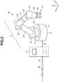
- Fig. 2 is a diagram illustrating a configuration of the robot apparatus 1 according to the present exemplary embodiment.
- a six-axis multi-joint robot will be described as an example of the robot apparatus.
- the robot apparatus 1 includes a base 10, a robot arm main body 50 having six joints J1 to J6, and an end effector 11 for grasping a work.
- the robot apparatus 1 is connected to the robot system control apparatus 13 via a cable 12.
- the robot system control apparatus 13 includes a network card for connection to an external network and is connected to the communication apparatus 60 via a cable 14 to be connected to the external network.
- a robot hand having three finger parts will be described as an example of the end effector 11.
- a mechanism capable of executing a task on a work e.g., an end effector that holds a work with an adsorption mechanism provided instead of the finger parts, may be used separately.
- the robot system control apparatus 13 is configured of a central processing unit (CPU) consisting of a microprocessor.
- An external input device may be connected to the robot system control apparatus 13.
- a teaching pendant which enables a teacher to directly teach the robot apparatus 1 in the vicinity thereof can be given as an example of the external input device.
- the teacher inputs a command value to the robot control apparatus 13 by using the external input device, and a control value from the control apparatus 13 is transmitted to the robot arm main body 50 and the end effector 11, which causes the robot apparatus 1 to perform an operation such as arrangement of a work on the tray 152. Then, the robot apparatus 1 operates the work to manufacture an article.
- the robot system control apparatus 13 includes a read only memory (ROM) which stores a program for controlling a corresponding driving unit depending on various movements of the robot arm main body 50 and data necessary for executing the control.
- the robot system control apparatus 13 further includes a random access memory (RAM), on which data, a setting value, and a program necessary for controlling the robot arm main body 50 are loaded, and which is also used as a work area of the CPU.
- ROM read only memory
- RAM random access memory
- the robot arm main body 50 is configured of a plurality of links connected to each other via a plurality of joints (six axes) through a serial link method.
- the links 51, 52, 53, 54, 55, and 56 of the robot arm main body 50 are driven via the joints J1, J2, J3, J4, J5, and J6.
- Each of the joints includes a motor (not illustrated) serving as a driving source.
- the base 10 and the link 51 of the robot arm main body 50 are connected by the joint J1 rotating about a rotation axis in a Z-axis direction.
- the joint J1 has a movable range of approximately ⁇ 180 degrees from an initial orientation.
- the links 51 and 52 of the robot arm main body 50 are connected by the joint J2.
- a rotation axis of the joint J2 conforms to an X-axis direction in the state illustrated in Fig. 2 .
- the joint J2 has a movable range of approximately ⁇ 80 degrees from an initial orientation.
- the links 52 and 53 of the robot arm main body 50 are connected by the joint J3.
- a rotation axis of the joint J3 conforms to the X-axis direction in the state illustrated in Fig. 2 .
- the joint J3 has a movable range of approximately ⁇ 70 degrees from an initial orientation.
- the links 53 and 54 of the robot arm main body 50 are connected by the joint J4.
- a rotation axis of the joint J4 conforms to a Y-axis direction in the state illustrated in Fig. 2 .
- the joint J4 has a movable range of approximately ⁇ 180 degrees from an initial orientation.
- the links 54 and 55 of the robot arm main body 50 are connected by the joint J5.
- a rotation axis of the joint J5 conforms to the X-axis direction.
- the joint J5 has a movable range of approximately ⁇ 120 degrees from an initial orientation.
- the links 55 and 56 of the robot arm main body 50 are connected by the joint J6.
- a rotation axis of the joint J6 conforms to the Z-axis direction.
- the joint J6 has a movable range of approximately ⁇ 240 degrees from an initial orientation.
- a robot hand for executing assembling work or transportation work in a production line is employed as the end effector 11 connected to a leading end of the robot arm main body 50.
- the end effector 11 can be attached to the link 56 either by a semi-fixation method such as screwing or by an attaching-detaching method such as latching.
- such a method can be considered that the robot arm main body 50 is controlled to attach or replace with another end effector 11 disposed on a supply position through a movement of the robot arm main body 50 itself.
- a torque sensor and an encoder are arranged on each of the joints J1 to J6.
- Fig. 3 is a diagram illustrating a configuration of the imaging apparatus 2.
- an imaging apparatus capable of executing panning, tilting, and zooming will be described as an example.
- the imaging apparatus 2 includes a camera base 20, a movable unit 21, and an imaging unit 22 inside the movable unit 21.
- the movable unit 21 includes a tilt motor, and the imaging unit 22 is provided therein via a transmission mechanism such as a shaft and a bearing, which enables the imaging unit 22 to rotate in a tilt direction indicated by an arrow A.
- the movable unit 21 includes a pan motor, and the imaging unit 22 is provided therein via a transmission mechanism such as a shaft and a bearing, which enables the imaging unit 22 to rotate in a pan direction indicated by an arrow B.
- a transmission mechanism such as a shaft and a bearing
- the imaging apparatus 2 includes a network card for connection to an external network and is connected to the communication apparatus 60 via a cable 23 to be connected to the external network.
- the imaging apparatus 2 can image the robot apparatus 1 and a predetermined position in the vicinity thereof by the movable unit 21, so that a captured image can be displayed on the display 31 of the computer 3 in the remote location via the communication apparatus 60.
- Fig. 4 is a diagram illustrating the computer 3 which enables an operator to operate the robot apparatus 1 based on a captured image acquired from the imaging apparatus 2.
- the computer 3 includes an operation system (OS) 30, a display 31, a keyboard 32, and a mouse 33.
- OS operation system
- An interface for controlling the robot apparatus 1 in a remote location and a captured image imaged by the imaging apparatus 2 are displayed on the display 31.
- the OS 30 includes a network card for connection to an external network and is connected to the communication apparatus 60 via a cable 34 to be connected to the external network.
- the operator can input a command value by using the keyboard 32 and the mouse 33 to operate the robot apparatus 1 and the imaging apparatus 2 from the remote location based on the information displayed on the display 31.
- an abnormal stop position a position where the robot apparatus 1 is stopped.
- the robot apparatus 1 has to be moved to a position specified as an initial starting point in the normal operation. This position is called a restore position, and the operation of the robot apparatus 1 from the abnormal stop position to the restore position is called restoration.
- the operator checks a state of the robot apparatus 1 from the remote location by using the imaging apparatus 2, creates and executes a restoration trajectory of the robot apparatus 1, and monitors the robot apparatus 1 being in operation.
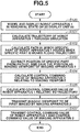
- Fig. 5 is a flowchart illustrating a control method of the robot apparatus 1 and the imaging apparatus 2 according to the present exemplary embodiment.
- the control method consists of eight processing steps S100 to S107. The specific method executed in each of the processing steps will be described below with reference to the diagrams.
- Fig. 6A is a diagram illustrating the abnormal stop position and the restore position of the robot apparatus 1 when the robot apparatus 1 that has been in operation is stopped abnormally.
- Fig. 6B is a diagram illustrating a screen structure of the display 31 of the computer 3 when the operator displays the robot apparatus 1 in an abnormal state in simulation.
- Figs. 6A and 6B illustrate a state where the end effector 11 of the robot apparatus 1 is stopped at an abnormal stop position 70, and the end effector 11 has to be restored to a restore position 71 above the work Wa.
- the robot system has a function of automatically generating a trajectory of the robot apparatus 1 based on information about a starting point and an ending point.
- a 3D model display unit 80 for executing 3D screen display and a trajectory generation display unit 90 for creating a trajectory of the robot apparatus 1 are displayed on the screen of the computer 3.
- the actually arranged robot apparatus 1 and work are displayed on the 3D model display unit 80 as 3D model simulation.
- the operator can appropriately move movable objects such as the robot apparatus 1 and the conveyer belt 150 by using the keyboard 32 and the mouse 33.
- a symbol ['] is attached to a reference number of an object displayed on the 3D model display unit 80.
- the trajectory generation display unit 90 includes a starting point selection box 91 for setting a starting point and an ending point selection box 92 for setting an ending point. Teaching points created by the operator are displayed inside the starting point selection box 91 and the ending point selection box 92, so that the operator can make a selection.
- the trajectory generation display unit 90 further includes a trajectory generation button 93, a trajectory reproducing button 94, a temporary stop button 95, and a stop button 96.
- processing for calculating a trajectory of the robot apparatus 1 from a teaching point selected in the starting point selection box 91 to a teaching point selected in the ending point selection box 92 is executed.
- the calculation of the trajectory is executed using a technique such as the rapidly-exploring random trees (RRT).
- RRT rapidly-exploring random trees
- the trajectory used herein represents displacement values of the respective joints J1 to J6 of the robot apparatus 1 for each control cycle.
- the trajectory is expressed by a total of 500 sets of displacement values of the joints J1 to J6.
- this processing flow is started when the robot apparatus 1 is stopped at the abnormal stop position because of occurrence of abnormality in the robot apparatus 1, and the processing proceeds to step S100.
- step S100 when abnormality has occurred in the actually arranged robot apparatus 1, the robot system control apparatus 13 and the OS 30 communicate with each other, and the robot apparatus 1' on the 3D model display unit 80 is displayed to be in an orientation the same as that of the robot apparatus 1.
- the OS 30 receives detection values of the encoders provided in the joints J1 to J6 of the robot apparatus 1 in the abnormal state from the robot system control apparatus 13, and displays the modeled robot apparatus 1' based on the detection values of the encoders. With this processing, the robot apparatus 1' can be displayed on the 3D model display unit 80 to be in an orientation the same as that of the robot apparatus 1 when abnormality has occurred.
- step S101 based on a predetermined instruction received from the operator in the remote location, a trajectory of the robot apparatus 1 which causes the end effector 11 to be moved from the abnormal stop position to the restore position is created in simulation.
- the operator inputs the abnormal stop position 70 as a starting point and the restore position 71 as an ending point.
- step S102 a path of the end effector 11 is calculated based on the trajectory of the robot apparatus 1 calculated in step S101.
- the path used herein represents transition of a position at which the specific part of the robot apparatus 1 is arranged for each control cycle of the trajectory when the robot apparatus 1 is moved along the trajectory.
- the end effector 11 is set as the specific part.
- the control cycle of the robot apparatus 1 is 4 ms and the operation of the robot apparatus 1 takes 2000 ms
- the end effector 11 is sequentially moved to 500 positions in total based on 2000 ms/4 ms.
- a predetermined place such as any one of the joints J1 to J6 of the robot arm main body 50 can be specified as the specific part.
- a place selected as a specific part is specified as a position to be imaged by the imaging apparatus 2.
- the part can be selected as the specific part.
- a position of the end effector 11 can be calculated, and a path of the end effector 11 can be calculated.
- the processing in step S102 corresponds to path calculation processing.
- a path 81 is displayed on the 3D model display unit 80 ( Fig. 6B ).
- the operator may modify the trajectory of the robot apparatus 1 generated in step S101 while checking the path 81 and the captured image imaged by the imaging apparatus 2.
- step S103 an imaging viewpoint used for controlling the movable unit 21 of the imaging apparatus 2 is calculated.
- delay in communication from the remote location to the imaging apparatus 2 has to be taken into consideration. This is because a gap occurs between the movement of the robot apparatus 1 imaged by the imaging apparatus 2 and the movement of the actual robot apparatus 1 actually being in operation. Since the operator in the remote location operates the robot apparatus 1 based on the captured image imaged by the imaging apparatus 2, in a case where the gap has occurred, the operator may execute an unintended operation of the robot apparatus 1, which can cause trouble.
- an imaging viewpoint is extracted from the path 81 by taking a value of response time taken in communication from the remote location to the imaging apparatus 2 as a cycle.
- the response time refers to time taken to drive the imaging apparatus 2 based on a command value from a point in time when the teacher in the remote location inputs the command value to the imaging apparatus 2 by the OS 30.
- control cycle of the robot apparatus 1 is 4 ms and time taken to move the end effector 11 in the path 81 is 280 ms. At this time, the end effector 11 is sequentially moved to 70 positions in the path 81 based on 280 ms/4 ms.
- the response time between the imaging apparatus 2 and the OS 30 in the remote location is greater than the control cycle 4 ms of the robot apparatus 1.
- the response time between the imaging apparatus 2 and the OS 30 is 40 ms.
- the number of positions of the end effector 11 in the path 81 is 70. Therefore, it will take at least 2800 ms, based on 40 ms ⁇ 70 to drive the imaging apparatus 2 based on the command values input by the teacher to image all of the positions. Since an operation time of the robot apparatus 1 in the path 81 is 280 ms, there will be a gap between the robot apparatus 1 being imaged by the imaging apparatus 2 and the robot apparatus 1 that is actually being in operation.
- imaging viewpoints are calculated by dividing the operation time of the end effector 11 in the path 81 by the response time taken in communication between the imaging apparatus 2 and the OS 30.
- step S103 corresponds to imaging viewpoint calculation processing.
- Fig. 7 is a diagram illustrating a plurality of imaging viewpoints for imaging the path 81 by the imaging apparatus 2.
- a total of 7 imaging viewpoints including 6 imaging viewpoints 82 to 87 and the restore position 71 are illustrated in the path 81 where the end effector 11 is moved.
- the number of imaging viewpoints will be 8 in total if the abnormal stop position 70 is also added thereto.
- step S104 a control command value of the imaging apparatus 2 corresponding to each of the imaging viewpoints is calculated.
- the control command of the imaging apparatus 2 consists of a combination of a rotation amount of the pan motor and a rotation amount of the tilt motor.
- the above calculation is executed by the OS 30 by using a simulator in which the robot apparatus 1 and peripheral devices are modelled.
- the pan/tilt rotation amount can be calculated from a relative position relationship between the imaging viewpoint and the imaging apparatus. Further, a zoom amount of the imaging apparatus 2 may be adjusted based on a distance between the imaging viewpoint and the imaging apparatus 2.
- control command values of the imaging apparatus 2 By transmitting the above-described control command values to the imaging apparatus 2 via the OS 30 and the control apparatus 13, it is possible to move the imaging apparatus 2 to execute imaging at the imaging viewpoints calculated in step S103. In addition, the control command values of the imaging apparatus 2 cannot be transmitted collectively, so that it is necessary to continuously transmit the control command values in order to move the imaging apparatus 2 continuously.
- step S105 control command values of the robot apparatus 1 corresponding to the trajectory acquired in step S102 are calculated.
- control commands of the robot apparatus 1 can be considered in various forms, in the present exemplary embodiment, displacement values of the joints J1 to J6 for each control cycle, i.e., the trajectory itself, are taken as the control command values of the robot apparatus 1.
- the robot apparatus 1 By transmitting the control command values to the robot system control apparatus 13, the robot apparatus 1 can be operated from a remote location. Further, the control command values for moving the robot apparatus 1 from the starting point to the ending point can be collectively transmitted in advance.
- a first imaging viewpoint to be imaged by the imaging unit 22 of the imaging apparatus 2 is set.
- a position where the robot apparatus 1 is currently stopped abnormally i.e., the abnormal stop position 70, is set as the first imaging viewpoint.
- step S107 the control command values of the imaging apparatus 2 calculated in step S104 and the control command values of the robot apparatus 1 calculated in step S105 are transmitted to the robot system control apparatus 13. Whereas the control command values of the robot apparatus 1 can be transmitted collectively, the control command values of the imaging apparatus 2 cannot be transmitted collectively. Thus, the control command values need to be transmitted for each cycle specified in step S103. With this configuration, the viewpoint of the imaging apparatus 2 can be easily controlled to follow the movement of the robot apparatus 1.
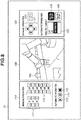
- Fig. 8 is a diagram illustrating a screen structure of the computer 3 when the operator monitors the movement of the robot apparatus 1.
- the display of the 3D model displayed on the display 31 is switched to a display of a captured image being imaged by the imaging apparatus 2.
- the display is set such that the operator can switch the display at an optional timing.
- an imaging display unit 100, a robot apparatus operation unit 110, and an imaging operation unit 120 are displayed on the display 31.
- the imaging display unit 100 is a cover unit for displaying a captured image being imaged by the imaging apparatus 2
- the robot apparatus operation unit 110 is an operation unit for operating the robot apparatus 1
- the imaging operation unit 120 is an operation unit for operating the imaging apparatus 2.
- the robot apparatus operation unit 110 consists of two operation portions respectively used for manually and automatically operating the robot apparatus 1.
- the robot apparatus operation unit 110 includes end effector operation buttons 111 for moving the end effector 11 of the robot apparatus 1 in the X-Y-Z direction in an optional coordinate system and joint operation buttons 112 for operating the rotation amount of each of the joints J1 to J6.
- the robot apparatus operation unit 110 includes an execute button 113 for executing the trajectory calculated in step S101 with the actual robot apparatus 1, a temporary stop button 114, and an emergency stop button 115.
- the imaging operation unit 120 also consists of two operation portions respectively used for manually and automatically operating the imaging apparatus 2.
- the manual operation includes viewpoint operation buttons 121 for executing pan/tilt operation of the imaging apparatus 2 and zoom operation buttons 122 for executing zoom-in/zoom-out operation.
- the display unit for executing automatic operation includes an imaging target box 123 for specifying an imaging target of the imaging apparatus 2. Parts relating to the robot apparatus 1 are displayed therein, and the path is calculated in step S102 based on the part selected therefrom.
- the robot apparatus 1 when the robot apparatus 1 is actually operated, there may occur an event unexpected by the operator.
- the viewpoint of the imaging apparatus 2 is automatically controlled to follow the movement of the robot apparatus 1, the operator can concentrate on the operation of the robot apparatus 1. Therefore, even in a case where an unexpected event has occurred, the operator can promptly take measures such as execution of emergency stop operation, so that the robot apparatus 1 can be prevented from being in contact with the peripheral devices.
- the imaging viewpoints are calculated by dividing the operation time of the end effector 11 in the path 81 by the response time taken in communication between the imaging apparatus 2 and the OS 30.
- the movement time of the end effector 11 and the imaging time of the imaging apparatus 2 can match each other, so that the movement can be prevented from being out of synchronization.
- the imaging viewpoint 82 subsequent to the abnormal stop position 70 may be set as a first imaging viewpoint in step S106. In this way, monitoring of the operation of the robot apparatus 1 can be executed in anticipation, so that contact of a predetermined position of the robot apparatus 1 with the peripheral device caused by the movement of the robot apparatus 1 can be prevented more reliably.
- the anticipated movement may be realized by moving the imaging apparatus 2 based on the imaging viewpoints first and then starting the movement of the robot apparatus 1 in the path 81 at a predetermined timing.
- the anticipated movement can be realized by moving the imaging apparatus 2 such that the end effector 11 is positioned within the imaging range again based on the imaging viewpoints.
- the path 81 calculated in step S102 and the imaging viewpoints calculated in step S103 may be displayed on the imaging display unit 100 together with the captured image imaged by the imaging apparatus 2.
- the 3D model display unit 80 and the imaging display unit 100 are displayed separately, the 3D model display unit 80 and the imaging display unit 100 may be displayed simultaneously. With this configuration, it is possible to confirm a difference in movement between the simulation and the actual apparatus.
- a control method of the robot system using an imaging apparatus will be described with reference to the drawings.
- a pan-tilt-zoom camera capable of operating a viewpoint through pan-tilt rotation has been described as an example.
- a camera capable of imaging the 360-degree surroundings thereof is also preferable.
- the present exemplary embodiment will be described below in detail.
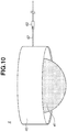
- Fig. 10 is a diagram illustrating a configuration of an imaging apparatus 4 according to the present exemplary embodiment.
- the imaging apparatus 4 is an omnidirectional camera provided with a camera base 40, an imaging unit 41, and a cable 42 used for network connection.
- the imaging unit 41 can execute imaging in a direction of 360 degrees based on a place where the imaging apparatus 4 is installed.
- the imaging apparatus 4 includes a network card for connection to an external network and is connected to the communication apparatus 60 via the cable 42 to be connected to the external network.
- the imaging apparatus 4 of the present exemplary embodiment does not have the mechanism for moving a viewpoint of the imaging unit or the zooming mechanism described in the first exemplary embodiment, the imaging apparatus 4 can execute digital zoom for locally enlarging a part of a captured image. Therefore, the imaging apparatus 4 in the present exemplary embodiment is controlled to execute digital zoom on a position corresponding to the imaging viewpoint, so that a viewpoint can be controlled to follow a target object to be desirable observed.
- a control method of the imaging apparatus 4 in the present exemplary embodiment is similar to that of the first exemplary embodiment illustrated in the flowchart of Fig. 5 , so that description thereof will be omitted.
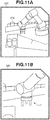
- Fig. 11 illustrates diagrams of the imaging display unit 100 that displays captured images being imaged by the imaging apparatus 4 of the present exemplary embodiment.
- Fig. 11A illustrates a captured image normally imaged by the imaging apparatus 4.
- Fig. 11B illustrates a captured image when digital zoom is executed with respect to a position corresponding to the imaging viewpoint calculated in step S103 of the first exemplary embodiment.
- an effect similar to that of the first exemplary embodiment can be achieved if the imaging apparatus 4 is controlled to execute digital zoom on an imaging viewpoint calculated with consideration for the path of the robot apparatus and a lag in communication with the imaging apparatus.
- the cost may increase because driving sources such as a pan motor and a tilt motor are needed, cost of the omnidirectional camera can be reduced because no motor is provided thereon.
- the imaging viewpoint may be displayed by adjusting a magnification ratio of the image displayed by the imaging apparatus 4 with a lens in addition to the above-described digital zoom based on image processing.
- a marker 141 is displayed at a position corresponding to the imaging viewpoint in the captured image imaged by the imaging apparatus.
- the operator can closely observe the specific part while viewing the entirety of the robot apparatus 1, so that the movement of the robot apparatus 1 can be easily monitored from a remote location.
- the processing procedures described in the first and the second exemplary embodiments are executed by the control apparatus 13 and the OS 30. Accordingly, a control program of software capable of executing the above-described functions and a storage medium storing that program constitute the present invention.
- a ROM or a RAM has been described as a computer readable storage medium, and the control program is stored in the ROM or the RAM; however, the present invention is not limited to these exemplary embodiments.
- the control program for implementing the present invention may be stored in a storage medium of any type as long as the storage medium is readable by a computer.
- a hard disk drive (HDD) an external storage device, or a recording disk may be used as a storage medium for supplying the control program.
- a control unit may be arranged on an imaging apparatus, the above-described control program and trajectory data of the robot apparatus may be stored in that control unit, and the first and the second exemplary embodiments can be implemented by the imaging apparatus alone.
- a six-axis multi-joint robot having six joints has been described as the robot arm main body 50, the number of joints is not limited thereto.
- a vertical multi-axis structure has been described as the form of the robot arm main body 50, a configuration similar to the above-described configuration can be implemented in the joints of the robot arm main body 50 of a different form such as a parallel-link type.
- a configuration example of the robot arm main body 50 is illustrated in Fig. 2 , the configuration is not limited thereto, and the design can be altered arbitrarily by those skilled in the art. Further, the motors of the robot arm main body 50 are not limited to the above-described configurations, and devices such as artificial muscles may be used as the driving sources for driving the respective joins.
- imaging viewpoints may be imaged by using a plurality of imaging apparatuses and cooperatively controlling the plurality of imaging apparatuses.
- a screen structure for monitoring the movement of the robot apparatus imaged by the imaging apparatus is displayed on the display 31 of the computer 3 in Figs. 8 , 9 , 11 , 12 , but this is not limitative.
- the screen structure may be displayed on various interfaces, such as an external input device such as a teaching pendant and a mobile terminal capable of operating the robot apparatus via an application.
Landscapes
- Engineering & Computer Science (AREA)
- Robotics (AREA)
- Mechanical Engineering (AREA)
- Automation & Control Theory (AREA)
- Evolutionary Computation (AREA)
- Artificial Intelligence (AREA)
- Physics & Mathematics (AREA)
- Fuzzy Systems (AREA)
- Mathematical Physics (AREA)
- Software Systems (AREA)
- Human Computer Interaction (AREA)
- Computer Networks & Wireless Communication (AREA)
- Manipulator (AREA)
Abstract
Description
- The present invention relates to a robot system.
- In recent years, work executed in a factory production line such as assembling, transportation, and painting work have been automated by a robot system in which a robot apparatus is used. A multi-joint robot using a robot arm having a plurality of rotary-drive joints and a vertical multi-joint robot using a robot arm having a plurality of horizontal-drive arm links are given as examples of the robot apparatus.
- With progress in a control technique of the robot system, a desired operation command can be given to a robot apparatus from a remote location. For example, two apparatuses, a control apparatus that controls the robot apparatus and a computer operated by an operator in a remote location, are connected to a network, and the robot apparatus is displayed on a screen of the computer through an imaging apparatus, such as a network camera. In this way, the operator in the remote location can operate the robot apparatus on the computer screen.
- Thus, even in a case where an abnormality has occurred in the robot apparatus in a factory and the operator has to conduct a maintenance work of the robot apparatus by visual recognition, the operator can conduct the maintenance work from the remote location by using the imaging apparatus. It is therefore possible to plan to make the factory production line not only automated but also unmanned.
- The above-described unmanned factory production line can realize not only reduction of labor cost but also monitoring of a factory even in a case where entrance of an operator into the factory is not preferable because of the factory environmental, so that there is an increased demand for the unmanned factory.
- To operate the robot apparatus from the remote location by visual recognition by using the imaging apparatus as described above, what is important is a viewpoint of the imaging apparatus. In the event of an abnormality in the robot apparatus as described above, in a case where the robot apparatus is caused to execute a predetermined operation in order to visually conduct a maintenance work from the remote location by visual recognition, there is a viewpoint which the operator wants to closely observe based on the operation of the robot apparatus.
- For example, in a case where a robot apparatus having a robot hand mounted on a leading end of a robot arm is used to conduct a maintenance work by operation like grasping a target object with using the robot hand, the operator has to closely observe the robot hand and the workpiece.
- Further, in a case where the robot arm of the robot apparatus is stopped because of occurrence of abnormality and restored to a predetermined orientation from the orientation of the stopped robot arm, a specific part of the robot arm may pass the vicinity of a nearby obstacle. In such a case, so as to urgently stop the robot arm if the specific part of the robot arm is about to be in contact with the nearby obstacle, the viewpoint of the imaging apparatus is desirably controlled to closely observe the vicinity of the specific part continuously while performing the operation to restore the robot arm.
- In
PTL 1, a method is discussed in which follow-up control of an imaging apparatus can be easily executed by detecting a movement trajectory of a target object to be closely observed by the imaging apparatus from a video image captured by the imaging apparatus. - PTL 1:
Japanese Patent Application Laid-Open No. 2016-111649 - The technique discussed in
PTL 1 allows the viewpoint of the imaging apparatus to be controlled to follow a target object by executing processing (image matching) for detecting a target object position in the video image imaged by the imaging apparatus. Therefore, in a case where the viewpoint of the imaging apparatus is to be controlled to follow the movement of the robot apparatus, a plurality of follow-up markers needs to be provided on respective parts of the robot. In many cases, various peripheral devices are installed in a robot apparatus used in a factory, so that it will be difficult to execute follow-up control of the viewpoint of the imaging apparatus if the follow-up markers are hidden behind the other peripheral devices. - In consideration of the above issue, the present invention is directed to a robot system capable of controlling a viewpoint of an imaging apparatus without using follow-up markers when a robot apparatus in which peripheral devices are installed is operated based on imaging executed by the imaging apparatus.
- In order to solve the above-described issue, the present invention employs a robot system including a robot apparatus and an imaging apparatus. The robot system includes a control apparatus configured to control the robot apparatus and the imaging apparatus, and the control apparatus controls, based on a path in which a predetermined part of the robot apparatus is moved, a movement of the imaging apparatus to image the predetermined part even if the robot apparatus is moved.
- According to an aspect of the present invention, based on a path of a target object that an operator wants to observe closely, an imaging apparatus is controlled to continuously execute imaging even if the target object is moved. With this configuration, a viewpoint of the imaging apparatus can be controlled without using a follow-up marker.
-
- [
Fig. 1] Fig. 1 is a diagram illustrating a configuration of arobot system 1000 according to an exemplary embodiment. - [
Fig. 2] Fig. 2 is a diagram illustrating a configuration of arobot apparatus 1 according to an exemplary embodiment. - [
Fig. 3] Fig. 3 is a diagram illustrating a configuration of animaging apparatus 2 according to an exemplary embodiment. - [
Fig. 4] Fig. 4 is a diagram illustrating a configuration of acomputer 3 according to an exemplary embodiment. - [
Fig. 5] Fig. 5 is a flowchart illustrating a control method according to an exemplary embodiment. - [
Fig. 6A] Fig. 6A is a diagram illustrating a state where therobot apparatus 1 according to the exemplary embodiment is stopped abnormally. - [
Fig. 6B] Fig. 6B is a diagram illustrating a state where therobot apparatus 1 according to the exemplary embodiment is stopped abnormally. - [
Fig. 7] Fig. 7 is a diagram illustrating a calculated path and imaging viewpoints according to an exemplary embodiment. - [
Fig. 8] Fig. 8 is a diagram illustrating a screen structure for monitoring therobot apparatus 1 being imaged by theimaging apparatus 2 according to the exemplary embodiment. - [
Fig. 9] Fig. 9 is a diagram illustrating a variation example of the screen structure for monitoring therobot apparatus 1 being imaged by theimaging apparatus 2 according to the exemplary embodiment. - [
Fig. 10] Fig. 10 is a diagram illustrating a configuration of animaging apparatus 4 according to an exemplary embodiment. - [
Fig. 11A] Fig. 11A is a diagram illustrating a screen structure for monitoring therobot apparatus 1 being imaged by theimaging apparatus 4 according to the exemplary embodiment. - [
Fig. 11B] Fig. 11B is a diagram illustrating a screen structure for monitoring therobot apparatus 1 being imaged by theimaging apparatus 4 according to the exemplary embodiment. - [
Fig. 12] Fig. 12 is a diagram illustrating a screen structure for monitoring therobot apparatus 1 being imaged by theimaging apparatus 2 according to the exemplary embodiment. - Hereinafter, exemplary embodiments embodying the present invention will be described with reference to the appended drawings. The exemplary embodiments described hereinafter are merely examples, and details of the configuration can be appropriately changed by those skilled in the art within a range which does not depart from the scope of the present invention. Further, a value mentioned in the present exemplary embodiment is a reference value, and is not intended to limit the present invention.
-
Fig. 1 is a diagram illustrating a schematic configuration of arobot system 1000 according to the present exemplary embodiment. In the present exemplary embodiment, a description will be given using an example of a task that therobot apparatus 1 executes to arrange works Wa to Wd conveyed through aconveyer belt 150 in a direction indicated by an arrow P onto atray 152. - The
robot system 1000 is configured of arobot apparatus 1, animaging apparatus 2 for imaging a status of therobot apparatus 1, a robotsystem control apparatus 13 for controlling therobot apparatus 1 and theimaging apparatus 2 and acomputer 3 that allows an operator to browse a video image captured by theimaging apparatus 2 from a remote location. Thecomputer 3 and the robotsystem control apparatus 13 are connected via acommunication apparatus 60 in a remotely-communicable state. - Herein, the remote location refers to a place where the operator cannot directly and visually recognize the
robot apparatus 1 as an operation target, but can visually recognize therobot apparatus 1 by using theimaging apparatus 2. - As illustrated in
Fig. 1 , theimaging apparatus 2 is installed on apole 155, and theimaging apparatus 2 images a movement of therobot apparatus 1 and displays an image of therobot apparatus 1 on adisplay 31 of thecomputer 3 installed in the remote location. Further,protection barriers robot apparatus 1. Theprotection barriers robot apparatus 1. -
Fig. 2 is a diagram illustrating a configuration of therobot apparatus 1 according to the present exemplary embodiment. In the present exemplary embodiment, a six-axis multi-joint robot will be described as an example of the robot apparatus. - As illustrated in
Fig. 2 , therobot apparatus 1 includes abase 10, a robot armmain body 50 having six joints J1 to J6, and anend effector 11 for grasping a work. Therobot apparatus 1 is connected to the robotsystem control apparatus 13 via acable 12. Further, the robotsystem control apparatus 13 includes a network card for connection to an external network and is connected to thecommunication apparatus 60 via acable 14 to be connected to the external network. - In the present exemplary embodiment, a robot hand having three finger parts will be described as an example of the
end effector 11. Although a robot hand having finger parts is given as an example in the present exemplary embodiment, a mechanism capable of executing a task on a work, e.g., an end effector that holds a work with an adsorption mechanism provided instead of the finger parts, may be used separately. - The robot
system control apparatus 13 is configured of a central processing unit (CPU) consisting of a microprocessor. An external input device may be connected to the robotsystem control apparatus 13. For example, a teaching pendant which enables a teacher to directly teach therobot apparatus 1 in the vicinity thereof can be given as an example of the external input device. - The teacher inputs a command value to the
robot control apparatus 13 by using the external input device, and a control value from thecontrol apparatus 13 is transmitted to the robot armmain body 50 and theend effector 11, which causes therobot apparatus 1 to perform an operation such as arrangement of a work on thetray 152. Then, therobot apparatus 1 operates the work to manufacture an article. - The robot
system control apparatus 13 includes a read only memory (ROM) which stores a program for controlling a corresponding driving unit depending on various movements of the robot armmain body 50 and data necessary for executing the control. The robotsystem control apparatus 13 further includes a random access memory (RAM), on which data, a setting value, and a program necessary for controlling the robot armmain body 50 are loaded, and which is also used as a work area of the CPU. - As illustrated in
Fig. 2 , for example, the robot armmain body 50 is configured of a plurality of links connected to each other via a plurality of joints (six axes) through a serial link method. Thelinks main body 50 are driven via the joints J1, J2, J3, J4, J5, and J6. Each of the joints includes a motor (not illustrated) serving as a driving source. - As illustrated in
Fig. 2 , thebase 10 and thelink 51 of the robot armmain body 50 are connected by the joint J1 rotating about a rotation axis in a Z-axis direction. For example, the joint J1 has a movable range of approximately ±180 degrees from an initial orientation. - The
links main body 50 are connected by the joint J2. A rotation axis of the joint J2 conforms to an X-axis direction in the state illustrated inFig. 2 . For example, the joint J2 has a movable range of approximately ±80 degrees from an initial orientation. - The
links main body 50 are connected by the joint J3. A rotation axis of the joint J3 conforms to the X-axis direction in the state illustrated inFig. 2 . For example, the joint J3 has a movable range of approximately ±70 degrees from an initial orientation. - The
links main body 50 are connected by the joint J4. A rotation axis of the joint J4 conforms to a Y-axis direction in the state illustrated inFig. 2 . For example, the joint J4 has a movable range of approximately ±180 degrees from an initial orientation. - The
links main body 50 are connected by the joint J5. A rotation axis of the joint J5 conforms to the X-axis direction. The joint J5 has a movable range of approximately ±120 degrees from an initial orientation. - The
links main body 50 are connected by the joint J6. A rotation axis of the joint J6 conforms to the Z-axis direction. The joint J6 has a movable range of approximately ±240 degrees from an initial orientation. - Further, a robot hand for executing assembling work or transportation work in a production line is employed as the
end effector 11 connected to a leading end of the robot armmain body 50. - The
end effector 11 can be attached to thelink 56 either by a semi-fixation method such as screwing or by an attaching-detaching method such as latching. - Particularly, in a case where the
end effector 11 is detachably mounted, such a method can be considered that the robot armmain body 50 is controlled to attach or replace with anotherend effector 11 disposed on a supply position through a movement of the robot armmain body 50 itself. - Further, in the present exemplary embodiment, in order to execute feedback control of driving of the joints J1 to J6, a torque sensor and an encoder (not illustrated) are arranged on each of the joints J1 to J6.
-
Fig. 3 is a diagram illustrating a configuration of theimaging apparatus 2. In the present exemplary embodiment, an imaging apparatus capable of executing panning, tilting, and zooming will be described as an example. - The
imaging apparatus 2 includes acamera base 20, amovable unit 21, and animaging unit 22 inside themovable unit 21. - The
movable unit 21 includes a tilt motor, and theimaging unit 22 is provided therein via a transmission mechanism such as a shaft and a bearing, which enables theimaging unit 22 to rotate in a tilt direction indicated by an arrow A. - Similarly, the
movable unit 21 includes a pan motor, and theimaging unit 22 is provided therein via a transmission mechanism such as a shaft and a bearing, which enables theimaging unit 22 to rotate in a pan direction indicated by an arrow B. - Further, the
imaging apparatus 2 includes a network card for connection to an external network and is connected to thecommunication apparatus 60 via acable 23 to be connected to the external network. - With the above described configuration, the
imaging apparatus 2 can image therobot apparatus 1 and a predetermined position in the vicinity thereof by themovable unit 21, so that a captured image can be displayed on thedisplay 31 of thecomputer 3 in the remote location via thecommunication apparatus 60. -
Fig. 4 is a diagram illustrating thecomputer 3 which enables an operator to operate therobot apparatus 1 based on a captured image acquired from theimaging apparatus 2. Thecomputer 3 includes an operation system (OS) 30, adisplay 31, akeyboard 32, and amouse 33. - An interface for controlling the
robot apparatus 1 in a remote location and a captured image imaged by theimaging apparatus 2 are displayed on thedisplay 31. - Further, the
OS 30 includes a network card for connection to an external network and is connected to thecommunication apparatus 60 via acable 34 to be connected to the external network. - With the above described configuration, the operator can input a command value by using the
keyboard 32 and themouse 33 to operate therobot apparatus 1 and theimaging apparatus 2 from the remote location based on the information displayed on thedisplay 31. - In the present exemplary embodiment, the description has been given using the example in which a task which the
robot apparatus 1 executes to arrange the works Wa to Wd conveyed through theconveyer belt 150 in a direction indicated by the arrow P on thetray 152. This operation of therobot apparatus 1 for arranging the works is executed according to an operation program created in advance. In the present exemplary embodiment, this operation is called normal operation. - However, there is a case where the operation of the
robot apparatus 1 is stopped because of occurrence of abnormality of some kind. For example, those cases can be considered in which therobot apparatus 1 is urgently stopped because a site operator accesses the vicinity of therobot apparatus 1 and in which some abnormality occurs during the normal operation because a different type of a work has been conveyed on theconveyer belt 150. - At this time, a position where the
robot apparatus 1 is stopped is called an abnormal stop position. Generally, in order for therobot apparatus 1 to be restored to the normal operation, therobot apparatus 1 has to be moved to a position specified as an initial starting point in the normal operation. This position is called a restore position, and the operation of therobot apparatus 1 from the abnormal stop position to the restore position is called restoration. - In order to execute the restoration, in the present exemplary embodiment, the operator checks a state of the
robot apparatus 1 from the remote location by using theimaging apparatus 2, creates and executes a restoration trajectory of therobot apparatus 1, and monitors therobot apparatus 1 being in operation. - At the time, in order to avoid the
robot apparatus 1 from being in contact with any peripheral device, when the operator operates therobot apparatus 1 based on imaging by theimaging apparatus 2, the operator is enabled to perform the above operation while easily confirming the safety without using a follow-up marker. Details will be described below. -
Fig. 5 is a flowchart illustrating a control method of therobot apparatus 1 and theimaging apparatus 2 according to the present exemplary embodiment. The control method consists of eight processing steps S100 to S107. The specific method executed in each of the processing steps will be described below with reference to the diagrams. - First, it is assumed that the
robot apparatus 1 is brought into the above-described abnormal state and the processing flow is started in a state therobot apparatus 1 is stopped at the abnormal stop position. -
Fig. 6A is a diagram illustrating the abnormal stop position and the restore position of therobot apparatus 1 when therobot apparatus 1 that has been in operation is stopped abnormally.Fig. 6B is a diagram illustrating a screen structure of thedisplay 31 of thecomputer 3 when the operator displays therobot apparatus 1 in an abnormal state in simulation. -
Figs. 6A and 6B illustrate a state where theend effector 11 of therobot apparatus 1 is stopped at anabnormal stop position 70, and theend effector 11 has to be restored to a restoreposition 71 above the work Wa. In the present exemplary embodiment, the robot system has a function of automatically generating a trajectory of therobot apparatus 1 based on information about a starting point and an ending point. - In
Fig. 6B , a 3Dmodel display unit 80 for executing 3D screen display and a trajectorygeneration display unit 90 for creating a trajectory of therobot apparatus 1 are displayed on the screen of thecomputer 3. - The actually arranged
robot apparatus 1 and work are displayed on the 3Dmodel display unit 80 as 3D model simulation. - The operator can appropriately move movable objects such as the
robot apparatus 1 and theconveyer belt 150 by using thekeyboard 32 and themouse 33. For the sake of convenience, a symbol ['] is attached to a reference number of an object displayed on the 3Dmodel display unit 80. - The trajectory
generation display unit 90 includes a startingpoint selection box 91 for setting a starting point and an endingpoint selection box 92 for setting an ending point. Teaching points created by the operator are displayed inside the startingpoint selection box 91 and the endingpoint selection box 92, so that the operator can make a selection. - The trajectory
generation display unit 90 further includes atrajectory generation button 93, atrajectory reproducing button 94, atemporary stop button 95, and astop button 96. - When the operator clicks the
trajectory generation button 93, processing for calculating a trajectory of therobot apparatus 1 from a teaching point selected in the startingpoint selection box 91 to a teaching point selected in the endingpoint selection box 92 is executed. - The calculation of the trajectory is executed using a technique such as the rapidly-exploring random trees (RRT). When the calculation of the trajectory is ended, the operator can check how the
robot apparatus 1 and theend effector 11 are actually moved on the 3Dmodel display unit 80 by clicking thetrajectory reproducing button 94. - The trajectory used herein represents displacement values of the respective joints J1 to J6 of the
robot apparatus 1 for each control cycle. For example, in a case where therobot apparatus 1 executes a movement that takes time of 2000 ms when the control cycle of therobot apparatus 1 is 4 ms, the trajectory is expressed by a total of 500 sets of displacement values of the joints J1 to J6. - Returning back to
Fig. 5 , this processing flow is started when therobot apparatus 1 is stopped at the abnormal stop position because of occurrence of abnormality in therobot apparatus 1, and the processing proceeds to step S100. - In step S100, when abnormality has occurred in the actually arranged
robot apparatus 1, the robotsystem control apparatus 13 and theOS 30 communicate with each other, and the robot apparatus 1' on the 3Dmodel display unit 80 is displayed to be in an orientation the same as that of therobot apparatus 1. - At this time, the
OS 30 receives detection values of the encoders provided in the joints J1 to J6 of therobot apparatus 1 in the abnormal state from the robotsystem control apparatus 13, and displays the modeled robot apparatus 1' based on the detection values of the encoders. With this processing, the robot apparatus 1' can be displayed on the 3Dmodel display unit 80 to be in an orientation the same as that of therobot apparatus 1 when abnormality has occurred. - Next, in step S101, based on a predetermined instruction received from the operator in the remote location, a trajectory of the
robot apparatus 1 which causes theend effector 11 to be moved from the abnormal stop position to the restore position is created in simulation. Herein, the operator inputs theabnormal stop position 70 as a starting point and the restoreposition 71 as an ending point. - Then, in step S102, a path of the
end effector 11 is calculated based on the trajectory of therobot apparatus 1 calculated in step S101. The path used herein represents transition of a position at which the specific part of therobot apparatus 1 is arranged for each control cycle of the trajectory when therobot apparatus 1 is moved along the trajectory. - In the present exemplary embodiment, the
end effector 11 is set as the specific part. When the control cycle of therobot apparatus 1 is 4 ms and the operation of therobot apparatus 1 takes 2000 ms, theend effector 11 is sequentially moved to 500 positions in total based on 2000 ms/4 ms. - Although the
end effector 11 is described as an example of the specific part of therobot apparatus 1 in the present exemplary embodiment, a predetermined place such as any one of the joints J1 to J6 of the robot armmain body 50 can be specified as the specific part. - A place selected as a specific part is specified as a position to be imaged by the
imaging apparatus 2. Thus, for example, if there is any part of therobot apparatus 1 which is likely to be in contact with theprotection barrier - By solving forward kinematics of the robot based on the trajectory, i.e., displacement of the respective joints J1 to J6 of the robot, a position of the
end effector 11 can be calculated, and a path of theend effector 11 can be calculated. The processing in step S102 corresponds to path calculation processing. - When the trajectory of the
robot apparatus 1 and the path of theend effector 11 are respectively calculated in steps S101 and S102, apath 81 is displayed on the 3D model display unit 80 (Fig. 6B ). In addition, the operator may modify the trajectory of therobot apparatus 1 generated in step S101 while checking thepath 81 and the captured image imaged by theimaging apparatus 2. - Next, in step S103, an imaging viewpoint used for controlling the
movable unit 21 of theimaging apparatus 2 is calculated. When theimaging apparatus 2 is controlled from the remote location, delay in communication from the remote location to theimaging apparatus 2 has to be taken into consideration. This is because a gap occurs between the movement of therobot apparatus 1 imaged by theimaging apparatus 2 and the movement of theactual robot apparatus 1 actually being in operation. Since the operator in the remote location operates therobot apparatus 1 based on the captured image imaged by theimaging apparatus 2, in a case where the gap has occurred, the operator may execute an unintended operation of therobot apparatus 1, which can cause trouble. - Therefore, in the present exemplary embodiment, an imaging viewpoint is extracted from the
path 81 by taking a value of response time taken in communication from the remote location to theimaging apparatus 2 as a cycle. The response time refers to time taken to drive theimaging apparatus 2 based on a command value from a point in time when the teacher in the remote location inputs the command value to theimaging apparatus 2 by theOS 30. - For example, it is assumed that the control cycle of the
robot apparatus 1 is 4 ms and time taken to move theend effector 11 in thepath 81 is 280 ms. At this time, theend effector 11 is sequentially moved to 70 positions in thepath 81 based on 280 ms/4 ms. - However, it is often the case that the response time between the
imaging apparatus 2 and theOS 30 in the remote location is greater than thecontrol cycle 4 ms of therobot apparatus 1. For example, it is assumed that the response time between theimaging apparatus 2 and theOS 30 is 40 ms. - According to the above-described calculation, the number of positions of the
end effector 11 in thepath 81 is 70. Therefore, it will take at least 2800 ms, based on 40 ms × 70 to drive theimaging apparatus 2 based on the command values input by the teacher to image all of the positions. Since an operation time of therobot apparatus 1 in thepath 81 is 280 ms, there will be a gap between therobot apparatus 1 being imaged by theimaging apparatus 2 and therobot apparatus 1 that is actually being in operation. - Therefore, imaging viewpoints are calculated by dividing the operation time of the
end effector 11 in thepath 81 by the response time taken in communication between theimaging apparatus 2 and theOS 30. - Because the operation time of the
end effector 11 in thepath 81 is 280 ms, and the response time taken in communication between theimaging apparatus 2 and theOS 30 is 40 ms, 7 positions of theend effector 11 in thepath 81 are extracted based on 280 ms / 40 ms to calculate the imaging viewpoints. With this calculation, the operation time of theend effector 11 and the imaging time of theimaging apparatus 2 can approximately match each other, so that the above-described gap can be reduced. The processing in step S103 corresponds to imaging viewpoint calculation processing. -
Fig. 7 is a diagram illustrating a plurality of imaging viewpoints for imaging thepath 81 by theimaging apparatus 2. A total of 7 imaging viewpoints including 6imaging viewpoints 82 to 87 and the restoreposition 71 are illustrated in thepath 81 where theend effector 11 is moved. The number of imaging viewpoints will be 8 in total if theabnormal stop position 70 is also added thereto. - Next, in step S104, a control command value of the
imaging apparatus 2 corresponding to each of the imaging viewpoints is calculated. The control command of theimaging apparatus 2 consists of a combination of a rotation amount of the pan motor and a rotation amount of the tilt motor. The above calculation is executed by theOS 30 by using a simulator in which therobot apparatus 1 and peripheral devices are modelled. The pan/tilt rotation amount can be calculated from a relative position relationship between the imaging viewpoint and the imaging apparatus. Further, a zoom amount of theimaging apparatus 2 may be adjusted based on a distance between the imaging viewpoint and theimaging apparatus 2. - By transmitting the above-described control command values to the
imaging apparatus 2 via theOS 30 and thecontrol apparatus 13, it is possible to move theimaging apparatus 2 to execute imaging at the imaging viewpoints calculated in step S103. In addition, the control command values of theimaging apparatus 2 cannot be transmitted collectively, so that it is necessary to continuously transmit the control command values in order to move theimaging apparatus 2 continuously. - Next, in step S105, control command values of the
robot apparatus 1 corresponding to the trajectory acquired in step S102 are calculated. Although the control commands of therobot apparatus 1 can be considered in various forms, in the present exemplary embodiment, displacement values of the joints J1 to J6 for each control cycle, i.e., the trajectory itself, are taken as the control command values of therobot apparatus 1. - By transmitting the control command values to the robot
system control apparatus 13, therobot apparatus 1 can be operated from a remote location. Further, the control command values for moving therobot apparatus 1 from the starting point to the ending point can be collectively transmitted in advance. - Next, in step S106, a first imaging viewpoint to be imaged by the
imaging unit 22 of theimaging apparatus 2 is set. In the present exemplary embodiment, a position where therobot apparatus 1 is currently stopped abnormally, i.e., theabnormal stop position 70, is set as the first imaging viewpoint. - Lastly, in step S107, the control command values of the
imaging apparatus 2 calculated in step S104 and the control command values of therobot apparatus 1 calculated in step S105 are transmitted to the robotsystem control apparatus 13. Whereas the control command values of therobot apparatus 1 can be transmitted collectively, the control command values of theimaging apparatus 2 cannot be transmitted collectively. Thus, the control command values need to be transmitted for each cycle specified in step S103. With this configuration, the viewpoint of theimaging apparatus 2 can be easily controlled to follow the movement of therobot apparatus 1. -
Fig. 8 is a diagram illustrating a screen structure of thecomputer 3 when the operator monitors the movement of therobot apparatus 1. When the processing up to step S107 is ended, the display of the 3D model displayed on thedisplay 31 is switched to a display of a captured image being imaged by theimaging apparatus 2. The display is set such that the operator can switch the display at an optional timing. - As illustrated in
Fig. 8 , when the movement of therobot apparatus 1 is monitored through theimaging apparatus 2, animaging display unit 100, a robotapparatus operation unit 110, and animaging operation unit 120 are displayed on thedisplay 31. - The
imaging display unit 100 is a cover unit for displaying a captured image being imaged by theimaging apparatus 2, the robotapparatus operation unit 110 is an operation unit for operating therobot apparatus 1, and theimaging operation unit 120 is an operation unit for operating theimaging apparatus 2. - The robot
apparatus operation unit 110 consists of two operation portions respectively used for manually and automatically operating therobot apparatus 1. - As a method for manual operation, the robot
apparatus operation unit 110 includes endeffector operation buttons 111 for moving theend effector 11 of therobot apparatus 1 in the X-Y-Z direction in an optional coordinate system andjoint operation buttons 112 for operating the rotation amount of each of the joints J1 to J6. - Further, for the case of executing automatic operation, the robot
apparatus operation unit 110 includes an executebutton 113 for executing the trajectory calculated in step S101 with theactual robot apparatus 1, atemporary stop button 114, and anemergency stop button 115. - The
imaging operation unit 120 also consists of two operation portions respectively used for manually and automatically operating theimaging apparatus 2. - The manual operation includes
viewpoint operation buttons 121 for executing pan/tilt operation of theimaging apparatus 2 andzoom operation buttons 122 for executing zoom-in/zoom-out operation. - Further, the display unit for executing automatic operation includes an
imaging target box 123 for specifying an imaging target of theimaging apparatus 2. Parts relating to therobot apparatus 1 are displayed therein, and the path is calculated in step S102 based on the part selected therefrom. - The operator clicks a follow-up ON
button 124 in a case where the operator wants to execute automatic imaging control based on the imaging viewpoints calculated in step S103. The operator clicks a follow-upOFF button 125 in a case where follow-up by theimaging apparatus 2 is not needed. - An operation control method of the viewpoint of the
imaging apparatus 1 for following the movement of therobot apparatus 1 according to the present exemplary embodiment has been described above. By setting the follow-up button 124 to ON and pressing the executebutton 113 for executing automatic operation of therobot apparatus 1, the camera can be easily controlled to follow the movement of therobot apparatus 1 without making advance preparations such as arrangement of the follow-up markers. In this way, it is possible to prevent difficulty in controlling the viewpoint of the imaging apparatus caused by the follow-up markers hidden behind the peripheral devices. - Further, when the
robot apparatus 1 is actually operated, there may occur an event unexpected by the operator. However, because the viewpoint of theimaging apparatus 2 is automatically controlled to follow the movement of therobot apparatus 1, the operator can concentrate on the operation of therobot apparatus 1. Therefore, even in a case where an unexpected event has occurred, the operator can promptly take measures such as execution of emergency stop operation, so that therobot apparatus 1 can be prevented from being in contact with the peripheral devices. - Further, when imaging viewpoints of the
imaging apparatus 2 are set, the imaging viewpoints are calculated by dividing the operation time of theend effector 11 in thepath 81 by the response time taken in communication between theimaging apparatus 2 and theOS 30. With this method, the movement time of theend effector 11 and the imaging time of theimaging apparatus 2 can match each other, so that the movement can be prevented from being out of synchronization. - If the
imaging apparatus 2 has a field of view sufficient for imaging theend effector 11 and the vicinity thereof to some extent, theimaging viewpoint 82 subsequent to theabnormal stop position 70 may be set as a first imaging viewpoint in step S106. In this way, monitoring of the operation of therobot apparatus 1 can be executed in anticipation, so that contact of a predetermined position of therobot apparatus 1 with the peripheral device caused by the movement of therobot apparatus 1 can be prevented more reliably. - In addition, the anticipated movement may be realized by moving the
imaging apparatus 2 based on the imaging viewpoints first and then starting the movement of therobot apparatus 1 in thepath 81 at a predetermined timing. Although theend effector 11 is temporarily out of the imaging range of theimaging apparatus 2 at this time, the anticipated movement can be realized by moving theimaging apparatus 2 such that theend effector 11 is positioned within the imaging range again based on the imaging viewpoints. - Further, as illustrated in
Fig. 9 , thepath 81 calculated in step S102 and the imaging viewpoints calculated in step S103 may be displayed on theimaging display unit 100 together with the captured image imaged by theimaging apparatus 2. With this configuration, it is possible to anticipate how therobot apparatus 1 is moved next, thereby preventing the predetermined position of therobot apparatus 1 from being in contact with the peripheral devices. - Although, in the present exemplary embodiment, the 3D
model display unit 80 and theimaging display unit 100 are displayed separately, the 3Dmodel display unit 80 and theimaging display unit 100 may be displayed simultaneously. With this configuration, it is possible to confirm a difference in movement between the simulation and the actual apparatus. - A control method of the robot system using an imaging apparatus according to a second exemplary embodiment of the present invention will be described with reference to the drawings. In the first exemplary embodiment, a pan-tilt-zoom camera capable of operating a viewpoint through pan-tilt rotation has been described as an example. According to the present exemplary embodiment, a camera capable of imaging the 360-degree surroundings thereof is also preferable. The present exemplary embodiment will be described below in detail.
- Hereinafter, configurations of hardware and a control system different from those described in the first exemplary embodiment will be described. Further, it is understood that configurations and effects similar to those described above can be realized by the portions similar to the first exemplary embodiment, so that detailed descriptions thereof will be omitted.
-
Fig. 10 is a diagram illustrating a configuration of animaging apparatus 4 according to the present exemplary embodiment. Theimaging apparatus 4 is an omnidirectional camera provided with acamera base 40, animaging unit 41, and acable 42 used for network connection. Theimaging unit 41 can execute imaging in a direction of 360 degrees based on a place where theimaging apparatus 4 is installed. Further, theimaging apparatus 4 includes a network card for connection to an external network and is connected to thecommunication apparatus 60 via thecable 42 to be connected to the external network. - Although the
imaging apparatus 4 of the present exemplary embodiment does not have the mechanism for moving a viewpoint of the imaging unit or the zooming mechanism described in the first exemplary embodiment, theimaging apparatus 4 can execute digital zoom for locally enlarging a part of a captured image. Therefore, theimaging apparatus 4 in the present exemplary embodiment is controlled to execute digital zoom on a position corresponding to the imaging viewpoint, so that a viewpoint can be controlled to follow a target object to be desirable observed. - A control method of the
imaging apparatus 4 in the present exemplary embodiment is similar to that of the first exemplary embodiment illustrated in the flowchart ofFig. 5 , so that description thereof will be omitted. -
Fig. 11 illustrates diagrams of theimaging display unit 100 that displays captured images being imaged by theimaging apparatus 4 of the present exemplary embodiment.Fig. 11A illustrates a captured image normally imaged by theimaging apparatus 4.Fig. 11B illustrates a captured image when digital zoom is executed with respect to a position corresponding to the imaging viewpoint calculated in step S103 of the first exemplary embodiment. - As illustrated in
Fig. 11B , an effect similar to that of the first exemplary embodiment can be achieved if theimaging apparatus 4 is controlled to execute digital zoom on an imaging viewpoint calculated with consideration for the path of the robot apparatus and a lag in communication with the imaging apparatus. Although, in the pan-tilt-zoom camera, the cost may increase because driving sources such as a pan motor and a tilt motor are needed, cost of the omnidirectional camera can be reduced because no motor is provided thereon. - Further, the imaging viewpoint may be displayed by adjusting a magnification ratio of the image displayed by the
imaging apparatus 4 with a lens in addition to the above-described digital zoom based on image processing. - Further, as illustrated in
Fig. 12 , with respect to the position corresponding to the calculated imaging viewpoint, processing for adding a marker on a captured image may be executed. InFig. 11 , amarker 141 is displayed at a position corresponding to the imaging viewpoint in the captured image imaged by the imaging apparatus. - By providing a button to be pressed by the operator for automatically executing digital zoom on the
marker 141, the operator can closely observe the specific part while viewing the entirety of therobot apparatus 1, so that the movement of therobot apparatus 1 can be easily monitored from a remote location. - Specifically, the processing procedures described in the first and the second exemplary embodiments are executed by the
control apparatus 13 and theOS 30. Accordingly, a control program of software capable of executing the above-described functions and a storage medium storing that program constitute the present invention. - Further, in the above-described exemplary embodiments, a ROM or a RAM has been described as a computer readable storage medium, and the control program is stored in the ROM or the RAM; however, the present invention is not limited to these exemplary embodiments. The control program for implementing the present invention may be stored in a storage medium of any type as long as the storage medium is readable by a computer. For example, a hard disk drive (HDD), an external storage device, or a recording disk may be used as a storage medium for supplying the control program. Further, a control unit may be arranged on an imaging apparatus, the above-described control program and trajectory data of the robot apparatus may be stored in that control unit, and the first and the second exemplary embodiments can be implemented by the imaging apparatus alone.
- Although, in the above-described first and the second exemplary embodiments, a six-axis multi-joint robot having six joints has been described as the robot arm
main body 50, the number of joints is not limited thereto. Although a vertical multi-axis structure has been described as the form of the robot armmain body 50, a configuration similar to the above-described configuration can be implemented in the joints of the robot armmain body 50 of a different form such as a parallel-link type. - Although a configuration example of the robot arm
main body 50 is illustrated inFig. 2 , the configuration is not limited thereto, and the design can be altered arbitrarily by those skilled in the art. Further, the motors of the robot armmain body 50 are not limited to the above-described configurations, and devices such as artificial muscles may be used as the driving sources for driving the respective joins. - Further, although a
single imaging apparatus 2 and asingle imaging apparatus 4 are described in the first and the second exemplary embodiments, imaging viewpoints may be imaged by using a plurality of imaging apparatuses and cooperatively controlling the plurality of imaging apparatuses. - Further, in the first and the second exemplary embodiments, a screen structure for monitoring the movement of the robot apparatus imaged by the imaging apparatus is displayed on the
display 31 of thecomputer 3 inFigs. 8 ,9 ,11 ,12 , but this is not limitative. For example, the screen structure may be displayed on various interfaces, such as an external input device such as a teaching pendant and a mobile terminal capable of operating the robot apparatus via an application. - The present invention is not limited to the above-described embodiments, and various changes and modifications can be made without departing from the sprit and the scope of the present invention. Accordingly, the following claims are to be attached hereto in order to publicly disclose the scope of the present invention.
Claims (20)
- A robot system including a robot apparatus and an imaging apparatus, the robot system comprising:a control apparatus configured to control the robot apparatus and the imaging apparatus, andwherein the control apparatus controls, based on a path in which a predetermined part of the robot apparatus is moved, a movement of the imaging apparatus to image the predetermined part even if the robot apparatus is moved.
- The robot system according to claim 1,
wherein the control apparatus calculates, based on the path, a plurality of imaging viewpoints where the imaging apparatus executes imaging, and
wherein the control apparatus controls, based on the imaging viewpoints, the movement of the imaging apparatus to image the predetermined part even if the robot apparatus is moved. - The robot system according to claim 2, wherein the control apparatus controls, based on the imaging viewpoints, the movement of the imaging apparatus to execute imaging in anticipation of the movement of the robot apparatus.
- The robot system according to claim 3, wherein, when the anticipated movement is executed, the control apparatus first causes the imaging apparatus to move based on the imaging viewpoints and then causes the robot apparatus to move in the path.
- The robot system according to any one of claims 2 to 4, wherein the control apparatus calculates the imaging viewpoints by dividing time taken for the robot apparatus to move in the path by response time of the imaging apparatus.
- The robot system according to any one of claims 1 to 5,
wherein the imaging apparatus is a pan-tilt-zoom camera, and
wherein the control apparatus controls the pan-tilt-zoom camera to adjust an imaging direction to the imaging viewpoints. - The robot system according to any one of claims 1 to 5,
wherein the imaging apparatus is an omnidirectional camera, and
wherein the control apparatus controls the omnidirectional camera to enlarge the imaging viewpoints to execute imaging. - The robot system according to any one of claims 1 to 6, wherein the imaging apparatus is connected to a network via the control apparatus so as to be operable via the network.
- The robot system according to any one of claims 1 to 8,
wherein the robot apparatus is a robot arm having a plurality of joints, and
wherein the control apparatus calculates the path based on values of positions where the joints exist. - A control apparatus that controls a robot system including a robot apparatus and an imaging apparatus,
wherein the control apparatus controls, based on a path in which a predetermined part of the robot apparatus is moved, a movement of the imaging apparatus to image the predetermined part even if the robot apparatus is moved. - The control apparatus according to claim 10,
wherein the control apparatus calculates, based on the path, a plurality of imaging viewpoints where the imaging apparatus executes imaging, and
wherein the control apparatus controls, based on the imaging viewpoints, the movement of the imaging apparatus to image the predetermined part even if the robot apparatus is moved. - The control apparatus according to claim 11, comprising:a display unit configured to display an image being imaged by the imaging apparatus;a robot apparatus operation unit configured to operate the robot apparatus; andan imaging operation unit configured to operate the imaging apparatus,wherein the path and the imaging viewpoints are displayed on the image being imaged by the imaging apparatus.
- The control apparatus according to claim 12,
wherein the robot apparatus operation unit includes a first operation unit configured to manually operate the robot apparatus and a second operation unit configured to automatically operate the robot apparatus, and
wherein the imaging operation unit includes a third operation unit configured to manually operate the imaging apparatus and a fourth operation unit configured to automatically operate the imaging apparatus. - A control method of a robot system including a robot apparatus and an imaging apparatus,
wherein the robot system includes a control apparatus configured to control the robot apparatus and the imaging apparatus, and
wherein the control apparatus comprises imaging control for controlling, based on a path in which a predetermined part of the robot apparatus is moved, a movement of the imaging apparatus to continuously image the predetermined part even if the robot apparatus is moved. - The control method according to claim 14, further comprising imaging viewpoint calculation for calculating a plurality of imaging viewpoints where the imaging apparatus executes imaging based on the path,
wherein the imaging control controls, based on the imaging viewpoints, the movement of the imaging apparatus to continuously image the predetermined part even if the robot apparatus is moved. - A control program for executing the control method according to claim 14 or 15.
- A computer-readable storage medium storing the control program according to claim 16.
- A manufacturing method of an article using the robot system according to any one of claims 1 to 9, comprising manufacturing an article by operating a work by the robot apparatus.
- An imaging apparatus that images a robot apparatus,
wherein the imaging apparatus includes a control unit, and
wherein the control unit controls, based on a path in which a predetermined part of the robot apparatus is moved, a movement of the imaging apparatus to image the predetermined part even if the robot apparatus is moved. - The imaging apparatus according to claim 19,
wherein the control unit calculates, based on the path, a plurality of imaging viewpoints where the imaging apparatus executes imaging, and
wherein the control unit controls, based on the imaging viewpoints, the movement of the imaging apparatus to image the predetermined part even if the robot apparatus is moved.
Applications Claiming Priority (2)
| Application Number | Priority Date | Filing Date | Title |
|---|---|---|---|
| JP2018170833A JP7163115B2 (en) | 2018-09-12 | 2018-09-12 | ROBOT SYSTEM, ROBOT SYSTEM CONTROL METHOD, PRODUCT MANUFACTURING METHOD, CONTROL DEVICE, OPERATION DEVICE, IMAGING DEVICE, CONTROL PROGRAM, AND RECORDING MEDIUM |
| PCT/JP2019/031302 WO2020054281A1 (en) | 2018-09-12 | 2019-08-08 | Robot system, robot system control device, robot system control method, imaging device, control program, and recording medium |
Publications (2)
| Publication Number | Publication Date |
|---|---|
| EP3851255A1 true EP3851255A1 (en) | 2021-07-21 |
| EP3851255A4 EP3851255A4 (en) | 2022-06-15 |
Family
ID=69777263
Family Applications (1)
| Application Number | Title | Priority Date | Filing Date |
|---|---|---|---|
| EP19860262.5A Pending EP3851255A4 (en) | 2018-09-12 | 2019-08-08 | ROBOT SYSTEM, ROBOT SYSTEM CONTROL DEVICE, ROBOT SYSTEM CONTROL METHOD, IMAGING DEVICE, CONTROL PROGRAM AND RECORDING MEDIA |
Country Status (5)
| Country | Link |
|---|---|
| US (2) | US11992960B2 (en) |
| EP (1) | EP3851255A4 (en) |
| JP (2) | JP7163115B2 (en) |
| CN (1) | CN113165186B (en) |
| WO (1) | WO2020054281A1 (en) |
Families Citing this family (6)
| Publication number | Priority date | Publication date | Assignee | Title |
|---|---|---|---|---|
| JP7163115B2 (en) | 2018-09-12 | 2022-10-31 | キヤノン株式会社 | ROBOT SYSTEM, ROBOT SYSTEM CONTROL METHOD, PRODUCT MANUFACTURING METHOD, CONTROL DEVICE, OPERATION DEVICE, IMAGING DEVICE, CONTROL PROGRAM, AND RECORDING MEDIUM |
| JP7224559B2 (en) * | 2020-12-10 | 2023-02-17 | 三菱電機株式会社 | Remote control manipulator system and remote control support system |
| US12036678B2 (en) * | 2021-05-25 | 2024-07-16 | Fanuc Corporation | Transparent object bin picking |
| DE112021007653T5 (en) * | 2021-07-13 | 2024-03-14 | Fanuc Corporation | Programming handheld device, robot system and robot control device |
| WO2024089813A1 (en) * | 2022-10-26 | 2024-05-02 | 株式会社Fuji | Robot |
| WO2026042173A1 (en) * | 2024-08-20 | 2026-02-26 | 株式会社ニコン | Image processing system and image acquisition method |
Family Cites Families (46)
| Publication number | Priority date | Publication date | Assignee | Title |
|---|---|---|---|---|
| JPH0790493B2 (en) * | 1987-04-08 | 1995-10-04 | 株式会社日立製作所 | Control method for robot with hand vision |
| US5319443A (en) * | 1991-03-07 | 1994-06-07 | Fanuc Ltd | Detected position correcting method |
| US5521843A (en) * | 1992-01-30 | 1996-05-28 | Fujitsu Limited | System for and method of recognizing and tracking target mark |
| JPH06270076A (en) * | 1993-03-25 | 1994-09-27 | Nippon Steel Corp | Camera control device for remote control |
| JPH07244519A (en) * | 1994-03-04 | 1995-09-19 | Nippon Telegr & Teleph Corp <Ntt> | Motion control method of moving object by image |
| JP3394322B2 (en) * | 1994-05-19 | 2003-04-07 | ファナック株式会社 | Coordinate system setting method using visual sensor |
| US5553609A (en) * | 1995-02-09 | 1996-09-10 | Visiting Nurse Service, Inc. | Intelligent remote visual monitoring system for home health care service |
| CA2248909A1 (en) * | 1996-03-15 | 1997-09-25 | Zapa Digital Arts Ltd. | System for producing an animation sequence according to character behaviour characteristics |
| JPH10249786A (en) * | 1997-03-14 | 1998-09-22 | Yaskawa Electric Corp | Manipulator control device and operation support device |
| AU2001262962A1 (en) * | 2000-05-01 | 2001-11-12 | Irobot Corporation | Method and system for remote control of mobile robot |
| JP2002164066A (en) * | 2000-11-22 | 2002-06-07 | Mitsubishi Heavy Ind Ltd | Stacked heat exchanger |
| JP4032410B2 (en) * | 2001-11-09 | 2008-01-16 | ソニー株式会社 | Information processing system, information processing method, program, recording medium, and information processing apparatus |
| US7432949B2 (en) * | 2003-08-20 | 2008-10-07 | Christophe Remy | Mobile videoimaging, videocommunication, video production (VCVP) system |
| US20070075048A1 (en) * | 2005-09-30 | 2007-04-05 | Nachi-Fujikoshi Corp. | Welding teaching point correction system and calibration method |
| JP4153528B2 (en) * | 2006-03-10 | 2008-09-24 | ファナック株式会社 | Apparatus, program, recording medium and method for robot simulation |
| US7313464B1 (en) * | 2006-09-05 | 2007-12-25 | Adept Technology Inc. | Bin-picking system for randomly positioned objects |
| US8559699B2 (en) * | 2008-10-10 | 2013-10-15 | Roboticvisiontech Llc | Methods and apparatus to facilitate operations in image based systems |
| JP5505138B2 (en) * | 2010-07-05 | 2014-05-28 | 株式会社安川電機 | Robot apparatus and gripping method using robot apparatus |
| JP5449112B2 (en) * | 2010-11-18 | 2014-03-19 | 株式会社神戸製鋼所 | Welding status monitoring method and welding status monitoring device |
| JP5799516B2 (en) * | 2011-02-03 | 2015-10-28 | セイコーエプソン株式会社 | Robot apparatus, inspection apparatus, inspection program, and inspection method |
| JP2012187651A (en) * | 2011-03-09 | 2012-10-04 | Omron Corp | Image processing apparatus, image processing system, and guidance apparatus therefor |
| EP2729084A4 (en) * | 2011-07-07 | 2015-03-04 | Olympus Corp | Medical master slave manipulator |
| JP5892360B2 (en) * | 2011-08-02 | 2016-03-23 | ソニー株式会社 | Robot instruction apparatus, robot instruction method, program, and communication system |
| US20150142171A1 (en) * | 2011-08-11 | 2015-05-21 | Siemens Healthcare Diagnostics Inc. | Methods and apparatus to calibrate an orientation between a robot gripper and a camera |
| JP5561260B2 (en) * | 2011-09-15 | 2014-07-30 | 株式会社安川電機 | Robot system and imaging method |
| JP2014079824A (en) * | 2012-10-15 | 2014-05-08 | Toshiba Corp | Work screen display method and work screen display device |
| CN110279427B (en) * | 2012-12-10 | 2024-01-16 | 直观外科手术操作公司 | Collision avoidance during controlled movement of movable arm of image acquisition device and steerable device |
| JP6153366B2 (en) * | 2013-03-29 | 2017-06-28 | 株式会社バンダイナムコエンターテインメント | Image generation system and program |
| JP6322959B2 (en) * | 2013-11-05 | 2018-05-16 | セイコーエプソン株式会社 | Robot, robot system, and robot controller |
| US9283674B2 (en) * | 2014-01-07 | 2016-03-15 | Irobot Corporation | Remotely operating a mobile robot |
| US9259844B2 (en) * | 2014-02-12 | 2016-02-16 | General Electric Company | Vision-guided electromagnetic robotic system |
| EP3112096B1 (en) * | 2014-02-28 | 2020-10-14 | Sony Corporation | Robot arm apparatus, calibration method, and program |
| JP2016070762A (en) * | 2014-09-29 | 2016-05-09 | ファナック株式会社 | Detection method and detector for detecting three-dimensional position of object |
| JP6458474B2 (en) | 2014-12-10 | 2019-01-30 | 沖電気工業株式会社 | Surveillance system, video analysis apparatus, video analysis method and program |
| JP6605611B2 (en) * | 2015-09-03 | 2019-11-13 | 株式会社Fuji | Robot system |
| WO2017115425A1 (en) * | 2015-12-28 | 2017-07-06 | オリンパス株式会社 | Medical manipulator system |
| JP2017124468A (en) * | 2016-01-14 | 2017-07-20 | キヤノン株式会社 | Robot control method, component manufacturing method, robot apparatus, program, and recording medium |
| CN114627664B (en) * | 2016-08-26 | 2025-09-30 | 松下电器(美国)知识产权公司 | Three-dimensional information processing method and three-dimensional information processing device |
| JP2018075121A (en) * | 2016-11-08 | 2018-05-17 | ソニー株式会社 | Medical support arm apparatus |
| EP3591984A4 (en) * | 2017-02-28 | 2020-07-22 | Sony Corporation | INFORMATION PROCESSING DEVICE, INFORMATION PROCESSING PROCESS AND PROGRAM |
| JP6392922B1 (en) * | 2017-03-21 | 2018-09-19 | ファナック株式会社 | Apparatus for calculating region that is not subject to inspection of inspection system, and method for calculating region that is not subject to inspection |
| US10690466B2 (en) * | 2017-04-19 | 2020-06-23 | Global Tel*Link Corporation | Mobile correctional facility robots |
| WO2018213131A1 (en) * | 2017-05-18 | 2018-11-22 | Pcms Holdings, Inc. | System and method for distributing and rendering content as spherical video and 3d asset combination |
| US10816939B1 (en) * | 2018-05-07 | 2020-10-27 | Zane Coleman | Method of illuminating an environment using an angularly varying light emitting device and an imager |
| JP7163115B2 (en) | 2018-09-12 | 2022-10-31 | キヤノン株式会社 | ROBOT SYSTEM, ROBOT SYSTEM CONTROL METHOD, PRODUCT MANUFACTURING METHOD, CONTROL DEVICE, OPERATION DEVICE, IMAGING DEVICE, CONTROL PROGRAM, AND RECORDING MEDIUM |
| US11707842B2 (en) * | 2018-11-27 | 2023-07-25 | Fanuc Corporation | Robot system and coordinate conversion method |
-
2018
- 2018-09-12 JP JP2018170833A patent/JP7163115B2/en active Active
-
2019
- 2019-08-08 CN CN201980059795.4A patent/CN113165186B/en active Active
- 2019-08-08 WO PCT/JP2019/031302 patent/WO2020054281A1/en not_active Ceased
- 2019-08-08 EP EP19860262.5A patent/EP3851255A4/en active Pending
-
2021
- 2021-03-04 US US17/192,737 patent/US11992960B2/en active Active
-
2022
- 2022-10-19 JP JP2022167636A patent/JP7423726B2/en active Active
-
2024
- 2024-05-01 US US18/652,644 patent/US20240269857A1/en active Pending
Also Published As
| Publication number | Publication date |
|---|---|
| JP7423726B2 (en) | 2024-01-29 |
| JP7163115B2 (en) | 2022-10-31 |
| US20240269857A1 (en) | 2024-08-15 |
| US20210187751A1 (en) | 2021-06-24 |
| US11992960B2 (en) | 2024-05-28 |
| EP3851255A4 (en) | 2022-06-15 |
| CN113165186A (en) | 2021-07-23 |
| JP2022183308A (en) | 2022-12-08 |
| JP2020040184A (en) | 2020-03-19 |
| WO2020054281A1 (en) | 2020-03-19 |
| CN113165186B (en) | 2024-07-30 |
Similar Documents
| Publication | Publication Date | Title |
|---|---|---|
| US20240269857A1 (en) | Robot system, control apparatus of robot system, control method of robot system, imaging apparatus, and storage medium | |
| JP6814735B2 (en) | Remote control manipulator system and its operation method | |
| JP7490349B2 (en) | Input device, control method for input device, robot system, method for manufacturing article using robot system, control program and recording medium | |
| JP7041492B2 (en) | Robot system | |
| US20040189675A1 (en) | Augmented reality system and method | |
| CN112828846A (en) | Simulation devices and robotic systems using augmented reality | |
| CN114761180A (en) | Robot system | |
| JP7594643B2 (en) | Robot System | |
| JPH03213278A (en) | Remote control support system for robot | |
| KR102681939B1 (en) | robot system | |
| JP2005335000A (en) | Human intervention robot controller | |
| JPH02116494A (en) | Remote control device for robot | |
| Sukumar et al. | Augmented reality-based tele-robotic system architecture for on-site construction | |
| JP7364285B1 (en) | How the robot handling system works | |
| JP7799330B2 (en) | How the robotic operation system works | |
| JP7462046B2 (en) | Robot System | |
| CN120886234A (en) | A remote semi-automatic control method and system for a fire emergency robot | |
| JPH0283194A (en) | Monitor for robot |
Legal Events
| Date | Code | Title | Description |
|---|---|---|---|
| STAA | Information on the status of an ep patent application or granted ep patent |
Free format text: STATUS: THE INTERNATIONAL PUBLICATION HAS BEEN MADE |
|
| PUAI | Public reference made under article 153(3) epc to a published international application that has entered the european phase |
Free format text: ORIGINAL CODE: 0009012 |
|
| STAA | Information on the status of an ep patent application or granted ep patent |
Free format text: STATUS: REQUEST FOR EXAMINATION WAS MADE |
|
| 17P | Request for examination filed |
Effective date: 20210412 |
|
| AK | Designated contracting states |
Kind code of ref document: A1 Designated state(s): AL AT BE BG CH CY CZ DE DK EE ES FI FR GB GR HR HU IE IS IT LI LT LU LV MC MK MT NL NO PL PT RO RS SE SI SK SM TR |
|
| DAV | Request for validation of the european patent (deleted) | ||
| DAX | Request for extension of the european patent (deleted) | ||
| REG | Reference to a national code |
Ref country code: DE Ref legal event code: R079 Free format text: PREVIOUS MAIN CLASS: B25J0013080000 Ipc: B25J0009160000 |
|
| A4 | Supplementary search report drawn up and despatched |
Effective date: 20220516 |
|
| RIC1 | Information provided on ipc code assigned before grant |
Ipc: B25J 9/22 20060101ALI20220510BHEP Ipc: B25J 3/00 20060101ALI20220510BHEP Ipc: B25J 13/08 20060101ALI20220510BHEP Ipc: B25J 9/16 20060101AFI20220510BHEP |
|
| STAA | Information on the status of an ep patent application or granted ep patent |
Free format text: STATUS: EXAMINATION IS IN PROGRESS |
|
| 17Q | First examination report despatched |
Effective date: 20241220 |