EP3851241A1 - Method and system for preventing back strikes when laser drilling hollow parts - Google Patents
Method and system for preventing back strikes when laser drilling hollow parts Download PDFInfo
- Publication number
- EP3851241A1 EP3851241A1 EP21151529.1A EP21151529A EP3851241A1 EP 3851241 A1 EP3851241 A1 EP 3851241A1 EP 21151529 A EP21151529 A EP 21151529A EP 3851241 A1 EP3851241 A1 EP 3851241A1
- Authority
- EP
- European Patent Office
- Prior art keywords
- fluid
- hollow component
- internal cavity
- component
- holes
- Prior art date
- Legal status (The legal status is an assumption and is not a legal conclusion. Google has not performed a legal analysis and makes no representation as to the accuracy of the status listed.)
- Granted
Links
Images




Classifications
-
- B—PERFORMING OPERATIONS; TRANSPORTING
- B23—MACHINE TOOLS; METAL-WORKING NOT OTHERWISE PROVIDED FOR
- B23K—SOLDERING OR UNSOLDERING; WELDING; CLADDING OR PLATING BY SOLDERING OR WELDING; CUTTING BY APPLYING HEAT LOCALLY, e.g. FLAME CUTTING; WORKING BY LASER BEAM
- B23K26/00—Working by laser beam, e.g. welding, cutting or boring
- B23K26/36—Removing material
- B23K26/38—Removing material by boring or cutting
- B23K26/382—Removing material by boring or cutting by boring
- B23K26/389—Removing material by boring or cutting by boring of fluid openings, e.g. nozzles, jets
-
- B—PERFORMING OPERATIONS; TRANSPORTING
- B23—MACHINE TOOLS; METAL-WORKING NOT OTHERWISE PROVIDED FOR
- B23K—SOLDERING OR UNSOLDERING; WELDING; CLADDING OR PLATING BY SOLDERING OR WELDING; CUTTING BY APPLYING HEAT LOCALLY, e.g. FLAME CUTTING; WORKING BY LASER BEAM
- B23K26/00—Working by laser beam, e.g. welding, cutting or boring
- B23K26/36—Removing material
- B23K26/38—Removing material by boring or cutting
- B23K26/382—Removing material by boring or cutting by boring
-
- B—PERFORMING OPERATIONS; TRANSPORTING
- B23—MACHINE TOOLS; METAL-WORKING NOT OTHERWISE PROVIDED FOR
- B23K—SOLDERING OR UNSOLDERING; WELDING; CLADDING OR PLATING BY SOLDERING OR WELDING; CUTTING BY APPLYING HEAT LOCALLY, e.g. FLAME CUTTING; WORKING BY LASER BEAM
- B23K26/00—Working by laser beam, e.g. welding, cutting or boring
- B23K26/16—Removal of by-products, e.g. particles or vapours produced during treatment of a workpiece
-
- B—PERFORMING OPERATIONS; TRANSPORTING
- B23—MACHINE TOOLS; METAL-WORKING NOT OTHERWISE PROVIDED FOR
- B23K—SOLDERING OR UNSOLDERING; WELDING; CLADDING OR PLATING BY SOLDERING OR WELDING; CUTTING BY APPLYING HEAT LOCALLY, e.g. FLAME CUTTING; WORKING BY LASER BEAM
- B23K26/00—Working by laser beam, e.g. welding, cutting or boring
- B23K26/18—Working by laser beam, e.g. welding, cutting or boring using absorbing layers on the workpiece, e.g. for marking or protecting purposes
-
- B—PERFORMING OPERATIONS; TRANSPORTING
- B23—MACHINE TOOLS; METAL-WORKING NOT OTHERWISE PROVIDED FOR
- B23K—SOLDERING OR UNSOLDERING; WELDING; CLADDING OR PLATING BY SOLDERING OR WELDING; CUTTING BY APPLYING HEAT LOCALLY, e.g. FLAME CUTTING; WORKING BY LASER BEAM
- B23K37/00—Auxiliary devices or processes, not specially adapted for a procedure covered by only one of the other main groups of this subclass
- B23K37/006—Safety devices for welding or cutting
-
- B—PERFORMING OPERATIONS; TRANSPORTING
- B23—MACHINE TOOLS; METAL-WORKING NOT OTHERWISE PROVIDED FOR
- B23K—SOLDERING OR UNSOLDERING; WELDING; CLADDING OR PLATING BY SOLDERING OR WELDING; CUTTING BY APPLYING HEAT LOCALLY, e.g. FLAME CUTTING; WORKING BY LASER BEAM
- B23K2101/00—Articles made by soldering, welding or cutting
- B23K2101/001—Turbines
-
- B—PERFORMING OPERATIONS; TRANSPORTING
- B23—MACHINE TOOLS; METAL-WORKING NOT OTHERWISE PROVIDED FOR
- B23K—SOLDERING OR UNSOLDERING; WELDING; CLADDING OR PLATING BY SOLDERING OR WELDING; CUTTING BY APPLYING HEAT LOCALLY, e.g. FLAME CUTTING; WORKING BY LASER BEAM
- B23K2101/00—Articles made by soldering, welding or cutting
- B23K2101/04—Tubular or hollow articles
-
- F—MECHANICAL ENGINEERING; LIGHTING; HEATING; WEAPONS; BLASTING
- F01—MACHINES OR ENGINES IN GENERAL; ENGINE PLANTS IN GENERAL; STEAM ENGINES
- F01D—NON-POSITIVE DISPLACEMENT MACHINES OR ENGINES, e.g. STEAM TURBINES
- F01D5/00—Blades; Blade-carrying members; Heating, heat-insulating, cooling or antivibration means on the blades or the members
- F01D5/12—Blades
- F01D5/14—Form or construction
- F01D5/18—Hollow blades, i.e. blades with cooling or heating channels or cavities; Heating, heat-insulating or cooling means on blades
- F01D5/186—Film cooling
-
- F—MECHANICAL ENGINEERING; LIGHTING; HEATING; WEAPONS; BLASTING
- F01—MACHINES OR ENGINES IN GENERAL; ENGINE PLANTS IN GENERAL; STEAM ENGINES
- F01D—NON-POSITIVE DISPLACEMENT MACHINES OR ENGINES, e.g. STEAM TURBINES
- F01D5/00—Blades; Blade-carrying members; Heating, heat-insulating, cooling or antivibration means on the blades or the members
- F01D5/12—Blades
- F01D5/14—Form or construction
- F01D5/18—Hollow blades, i.e. blades with cooling or heating channels or cavities; Heating, heat-insulating or cooling means on blades
- F01D5/187—Convection cooling
-
- F—MECHANICAL ENGINEERING; LIGHTING; HEATING; WEAPONS; BLASTING
- F05—INDEXING SCHEMES RELATING TO ENGINES OR PUMPS IN VARIOUS SUBCLASSES OF CLASSES F01-F04
- F05D—INDEXING SCHEME FOR ASPECTS RELATING TO NON-POSITIVE-DISPLACEMENT MACHINES OR ENGINES, GAS-TURBINES OR JET-PROPULSION PLANTS
- F05D2230/00—Manufacture
- F05D2230/10—Manufacture by removing material
- F05D2230/13—Manufacture by removing material using lasers
-
- F—MECHANICAL ENGINEERING; LIGHTING; HEATING; WEAPONS; BLASTING
- F05—INDEXING SCHEMES RELATING TO ENGINES OR PUMPS IN VARIOUS SUBCLASSES OF CLASSES F01-F04
- F05D—INDEXING SCHEME FOR ASPECTS RELATING TO NON-POSITIVE-DISPLACEMENT MACHINES OR ENGINES, GAS-TURBINES OR JET-PROPULSION PLANTS
- F05D2250/00—Geometry
- F05D2250/10—Two-dimensional
- F05D2250/18—Two-dimensional patterned
- F05D2250/185—Two-dimensional patterned serpentine-like
-
- F—MECHANICAL ENGINEERING; LIGHTING; HEATING; WEAPONS; BLASTING
- F05—INDEXING SCHEMES RELATING TO ENGINES OR PUMPS IN VARIOUS SUBCLASSES OF CLASSES F01-F04
- F05D—INDEXING SCHEME FOR ASPECTS RELATING TO NON-POSITIVE-DISPLACEMENT MACHINES OR ENGINES, GAS-TURBINES OR JET-PROPULSION PLANTS
- F05D2260/00—Function
- F05D2260/20—Heat transfer, e.g. cooling
- F05D2260/221—Improvement of heat transfer
- F05D2260/2214—Improvement of heat transfer by increasing the heat transfer surface
- F05D2260/22141—Improvement of heat transfer by increasing the heat transfer surface using fins or ribs
Definitions
- This disclosure relates generally to the manufacture of cast components, and more particularly to laser drilling holes in hollow cast components.
- gas turbine engines include internal cooling passages as well as small-diameter cooling holes extending through the components.
- hollow castings such as airfoils for a high-pressure turbine, may be laser drilled to provide cooling holes extending between an internal cooling cavity or passage and an exterior surface of the casting.
- laser drilling of such components poses the problem of back striking which can lead to damage of internal walls of the casting during laser drilling.
- a method for forming a hollow component that includes injecting a fluid into an internal cavity of the hollow component to achieve a pressure of the fluid within the internal cavity that is greater than an ambient pressure.
- the method further includes drilling at least one hole through the hollow component from an external surface of the hollow component to the internal cavity by applying a laser beam to the hollow component with a laser generator.
- the method further includes directing the fluid from the internal cavity and through the at least one hole so as to exit the hollow component via the at least one hole.
- the at least one hole includes a plurality of holes.
- drilling the plurality of holes through the hollow component includes sequentially drilling each hole of the plurality of holes progressively from a first position of the hollow component to a second position of the hollow component.
- the second position is higher than the first position.
- injecting the fluid into the internal cavity of the hollow component includes controlling a flow rate of the fluid from a fluid source to the hollow component.
- the method further includes maintaining a predetermined fluid pressure within the internal cavity of the hollow component as the plurality of holes are sequentially drilled.
- the method further includes collecting the fluid which exits the plurality of holes.
- the method further includes returning the collected fluid to the fluid source.
- returning the collected fluid to the fluid source includes passing the fluid through a filter.
- the fluid includes water.
- the fluid further includes a dye.
- the method further includes flushing the hollow component with a second fluid, different than the fluid, subsequent to drilling the plurality of holes through the hollow component.
- the method further includes fluidly coupling the hollow component to the fluid source with a seal.
- a system that includes a hollow component including an external surface and an internal cavity.
- the hollow component includes at least one hole extending through the hollow component between the external surface and the internal cavity.
- the system further includes a drilling apparatus.
- the drilling apparatus includes a laser generator configured to apply a laser beam to the hollow component.
- the drilling apparatus further includes a fluid source containing a fluid.
- the drilling apparatus further includes a pump in fluid communication with the fluid source and the internal cavity of the hollow component. The pump is configured to inject the fluid into the internal cavity of the hollow component so as to achieve a pressure of the fluid within the internal component that is greater than an ambient pressure.
- the at least one hole includes a plurality of holes.
- the drilling apparatus further includes a collector disposed underneath the hollow component.
- the collector is fluidly coupled to the fluid source.
- the drilling apparatus further includes a filter fluidly coupling the collector and the fluid source.
- the drilling apparatus further includes a sensor configured to determine the pressure of the fluid in the internal cavity of the hollow component.
- the pump is configured to maintain a predetermined fluid pressure within the internal cavity of the hollow component.
- the fluid includes water.
- a method for forming a hollow component includes injecting a fluid into an internal cavity of the hollow component to achieve a pressure of the fluid within the internal cavity that is greater than an ambient pressure.
- the method further includes sequentially drilling a plurality of holes through the hollow component from an external surface of the hollow component to the internal cavity by applying a laser beam to the hollow component with a laser generator.
- the plurality of holes are drilled progressively from a first position of the hollow component to a second position of the hollow component. The second position is higher than the first position.
- the method further includes directing the fluid from the internal cavity and through the plurality of holes so as to exit the hollow component via the plurality of holes.
- the method further includes controlling a flow rate of the fluid from a fluid source to the hollow component so as to maintain a predetermined fluid pressure within the internal cavity of the hollow component as the plurality of holes are sequentially drilled.
- the gas turbine engine 10 is schematically illustrated.
- the gas turbine engine 10 is disclosed herein as a two-spool turbofan engine that generally includes a fan section 12, a compressor section 14, a combustor section 16, and a turbine section 18.
- the fan section 12 drives air along a bypass flowpath 20 while the compressor section 14 drives air along a core flowpath 22 for compression and communication into the combustor section 16 and then expansion through the turbine section 18.
- a turbofan gas turbine engine in the disclosed non-limiting embodiments, it should be understood that the concepts described herein are not limited to use with turbofans as the teachings may be applied to other types of turbine engines including those with three-spool architectures.
- the gas turbine engine 10 generally includes a low-pressure spool 24 and a high-pressure spool 26 mounted for rotation about a longitudinal centerline 28 of the gas turbine engine 10 relative to an engine static structure 30 via one or more bearing systems 32. It should be understood that various bearing systems 32 at various locations may alternatively or additionally be provided.
- the low-pressure spool 24 generally includes a first shaft 34 that interconnects a fan 36, a low-pressure compressor 38, and a low-pressure turbine 40.
- the first shaft 34 is connected to the fan 36 through a gear assembly of a fan drive gear system 42 to drive the fan 36 at a lower speed than the low-pressure spool 24.
- the high-pressure spool 26 generally includes a second shaft 44 that interconnects a high-pressure compressor 46 and a high-pressure turbine 48. It is to be understood that "low pressure” and "high pressure” or variations thereof as used herein are relative terms indicating that the high pressure is greater than the low pressure.
- An annular combustor 50 is disposed between the high-pressure compressor 46 and the high-pressure turbine 48 along the longitudinal centerline 28.
- the first shaft 34 and the second shaft 44 are concentric and rotate via the one or more bearing systems 32 about the longitudinal centerline 28 which is collinear with respective longitudinal centerlines of the first and second shafts 34, 44.
- Airflow along the core flowpath 22 is compressed by the low-pressure compressor 38, then the high-pressure compressor 46, mixed and burned with fuel in the combustor 50, and then expanded over the high-pressure turbine 48 and the low-pressure turbine 40.
- the low-pressure turbine 40 and the high-pressure turbine 48 rotationally drive the low-pressure spool 24 and the high-pressure spool 26, respectively, in response to the expansion.
- the gas turbine engine 10 may include one or more components 52 which may be configured as hollow castings.
- the component 52 may be an airfoil configured for use in the compressor section 14 and/or the turbine section 18 of the gas turbine engine.
- the component 52 may be any suitable gas turbine engine 10 component requiring the drilling of holes therethrough, such as, but not limited to, airfoils, vanes, combustor wall assembly components, etc.
- the component 52 includes a component body 54 defining one or more internal cavities 56.
- the component body 54 includes an external wall 64 having an external surface 58 and an internal surface 66.
- a plurality of holes 60 are formed through the component body 54 of the component 52 between the internal cavity 56 and the external surface 58.
- the plurality of holes 60 may be formed through the component body 54, for example, by drilling subsequent to formation of the component body 54. For example, laser drilling of the plurality of holes 60 may be used to quickly produce hundreds or thousands of holes with a high degree of accuracy. However, the component body 54 may be susceptible to damage from back strikes during laser drilling of the plurality of holes 60.
- a back strike is an event which occurs when, for example, a drill bit, laser, EDM electrode, machining process/component, etc. passes through the component body 54 from the external surface 58, into the internal cavity 56, and contacts an internal wall 62 of the component 52 or an internal surface 66 of the external wall 64 of the component 52, opposite the hole being drilled, potentially causing damage to the internal wall 62 or the internal surface 66 of the external wall 64 (see, e.g., FIG. 2B illustrating exemplary back strike locations 68 caused by, for example, a laser beam 304).
- the drilling apparatus 300 includes a laser generator 302 configured to apply the laser beam 304 to the component 52 for drilling the plurality of holes 60 through the component body 54 from the external surface 58 to the internal cavity 56.
- the laser generator 302 is configured to move in one or more of an x-, a y-, and a z-direction, rotate, and/or tilt relative to the component 52 so as to form each hole of the plurality of holes 60 in the desired location and with the desired orientation.
- the drilling apparatus 300 includes a fluid source 306 configured to contain a fluid 308.
- a pump 310 is in fluid communication with the fluid source 306 and the internal cavity 56 of the component 52 via one or more conduits 312.
- the pump 310 is configured to inject the fluid 308 into the internal cavity 56 of the component 52 so as to achieve a pressure of the fluid 308 within the internal cavity 56 that is greater than an ambient pressure (i.e., a pressure external to the component 52, e.g., atmospheric pressure).
- an ambient pressure i.e., a pressure external to the component 52, e.g., atmospheric pressure
- the fluid 308 may directed from the internal cavity 56 and through the plurality of holes 60, as the plurality of holes 60 are formed, so as to exit the component 52 via the plurality of holes 60.
- a seal 314 may be used to fluidly couple the fluid source 306, pump 310, and conduits 312 to the internal cavity 56 of the component 52 and to minimize or eliminate any leakage of fluid 308.
- the drilling apparatus 300 may include one or more sensors 316 disposed in the conduit 312 between the component 52 and the pump 310.
- the one or more sensors 316 may include, for example, fluid pressure sensors, fluid flow sensors, fluid temperature sensors, etc.
- the one or more sensors 316 may be in signal communication with the pump 310.
- the pump 310 may be, for example, a variable flow pump configured to control a flow rate of the fluid 308 injected into the internal cavity 56 of the component 52 based on an output of the one or more sensors 316.
- the pump 310 may include one or more valves configured to control the flow rate of the fluid 308 injected into the internal cavity 56 of the component 52.
- the drilling apparatus 300 may include a collector 318 configured to collect the fluid 308 which exits the component 52 via the plurality of holes 60.
- the collector 318 may be disposed underneath the component 52 such that fluid 308 exiting the component 52 via the plurality of holes 60 may fall into the collector 318.
- the collector 318 may be in fluid communication with the fluid source 306 via one or more conduits 320. Accordingly, fluid 308 which exits the component 52 via the plurality of holes 52 may be returned to the fluid source 306 and again injected into the internal cavity 56 of the component 52 by the pump 310.
- the drilling apparatus may include a filter 322 disposed between and in fluid communication with the collector 318 and the fluid source 306 to filter impurities (e.g., recast material formed during laser drilling of the component 52) from the fluid 308.
- impurities e.g., recast material formed during laser drilling of the component 52
- Step 502 the pump 310 injects the fluid 308 from the fluid source 306 into the internal cavity 56 of the component 52 to achieve a pressure of the fluid 308 within the internal cavity 56 that is greater than the ambient pressure external to the component 52.
- the laser generator 302 drills the plurality of holes 60 through the component 52 from the external surface 58 of the component 52 to the internal cavity 56 by applying the laser beam 304 to the component 52.
- the fluid 308 present in the internal cavity 56 may attenuate the laser beam 304 as it enters the internal cavity 56, thereby preventing or reducing damage to the internal wall 62 of the component 52 by preventing the back strike or reducing the energy density or concentration of the laser beam 304 such that the laser beam 304 does not damage the internal wall 62.
- Step 506 the fluid 308 is directed from the internal cavity 56 of the component 52 through the plurality of holes 60, as a result of the pressure of the fluid 308 in the internal cavity 56 greater than the ambient pressure, so as to exit the component 52 via the plurality of holes 60.
- the positive pressure of the fluid 308 within the internal cavity 56 relative to ambient pressure flow of the fluid 308 through a hole of the plurality of holes 60 may begin immediately upon completion of the hole from the external surface 58 to the internal cavity 56.
- the fluid 308 may, therefore, immediately provide cooling to the material of the component body 54 surrounding the hole and may cause molten material of the component body 54, formed during laser drilling, to solidify.
- Directing the fluid 308 out of the internal cavity 56 through the plurality of holes 60 may allow recast material (e.g., loose material of the component body 54 formed during laser drilling) and other debris to be flushed from the component 52.
- Directing the fluid 308 out of the internal cavity 56 through the plurality of holes 60 may also cause any air trapped within the internal cavity 56 to be flushed from the component 52 via the plurality of holes 60.
- Air trapped within the internal cavity 56 may prevent attenuation of a laser beam 304 entering the internal cavity 56 by causing the fluid 308 to be locally displaced. Accordingly, flushing trapped air from the internal cavity 56 by directing the fluid 308 to exit the internal cavity 56 via the plurality of holes 60 may further reduce the likelihood of damage to the internal wall 62 as a result of a back strike.
- drilling the plurality of holes 60 may include sequentially drilling each hole of the plurality of holes 60 progressively from a first position of the component 52 to a second position of the component 52 which is higher than the first position, relative to a gravitational field.
- fluid 308 exiting the plurality of holes 60 or fluid 308 disposed on the external surface 58 of the component 52 may not interfere with the laser drilling of subsequent holes of the plurality of holes which may be formed at a higher position relative to previously drilled holes.
- injecting the fluid 308 into the internal cavity 56 of the component 52 may include controlling a flow rate of the fluid 308, with the pump 310, from the fluid source 306 to the component 52.
- the pump 310 may maintain a predetermined pressure of the fluid 308 within the internal cavity 56 of the component 52 as the plurality of holes 60 are sequentially drilled.
- the pump 310 may maintain the predetermined pressure of the fluid 308 within the internal cavity 56 based on, for example, the output of the one or more sensors 316.
- the pump 310 may maintain a predetermined pressure of the fluid 308 within the internal cavity 56 which is greater than ambient pressure.
- the pump 310 may maintain a predetermined pressure of the fluid 308 within the internal cavity which is at least one pound per square inch (psi) (6.9 kPa) greater than the ambient pressure. Accordingly, as the number of holes in the plurality of holes 60 increases, the pump 310 may increase the rate of flow of the fluid 308 injected into the internal cavity 56 in order to maintain the predetermined pressure of the fluid 308 within the cavity (e.g., to compensate for the increasing number of holes of the plurality of holes 60).
- psi pound per square inch
- the predetermined pressure may be determined based on one or more factors, for example, a height of the component 52, a desired amount of cooling or flushing to be provided to the component 52, or a velocity of the fluid 308 exiting the component 52 via the plurality of holes 60.
- the method 500 may include collecting the fluid 308 exiting the component 52 via the plurality of holes 60 with the collector 318 in Step 508.
- the fluid 308 collected by the collector 318 may be returned to the fluid source 306 for reuse by the pump 310 in Step 502.
- returning the collected fluid to the fluid source 306 may include passing the fluid 308 through the filter 322 to remove any recast material or other debris from the component 52 prior to reintroducing the fluid 308 to the fluid source 306.
- the fluid 308 may be, for example, a liquid configured to absorb or scatter the laser beam 304 upon entry of the laser beam 304 into the internal cavity 56 of the component 52.
- the fluid 308 may be water.
- the fluid 308 may include one or more dyes configured to improve the laser energy attenuation effectiveness of the fluid 308.
- the dye may be an opaque dye and may be organic/carbon based (e.g., carbon black) such that the dye can be removed from the component 52 during a burnout cycle.
- the method 500 may include flushing the component 52 subsequent to laser drilling the plurality of holes 60 through the component 52, in Step 512.
- flushing the component 52 may be performed with a second fluid 324 which is different than the fluid 308. Flushing the component 52 with the second fluid 324 may allow dye, recast material, or debris to be removed from the component 52 after the laser drilling process has been completed.
- flushing the component 52 may include supplying the second fluid 324 to the internal cavity 56 of the component 52 and directing the second fluid 324 out of the component 52 through the plurality of holes 60 (see, e.g., FIG. 6A ).
- flushing the component 52 may include supplying the second fluid 324 to the external surface 58 of the component 52 and directing the second fluid 324 into the internal cavity 56 of the component 52 through the plurality of holes 60 and subsequently out of the component 52 (see, e.g., FIG. 6B ).
- the second fluid 324 used for flushing the component 52 may be collected in a manner similar to that described above with respect to Steps 508 and 510.
Landscapes
- Engineering & Computer Science (AREA)
- Physics & Mathematics (AREA)
- Optics & Photonics (AREA)
- Mechanical Engineering (AREA)
- Plasma & Fusion (AREA)
- Laser Beam Processing (AREA)
Abstract
Description
- This disclosure relates generally to the manufacture of cast components, and more particularly to laser drilling holes in hollow cast components.
- Many components of gas turbine engines include internal cooling passages as well as small-diameter cooling holes extending through the components. For example, hollow castings, such as airfoils for a high-pressure turbine, may be laser drilled to provide cooling holes extending between an internal cooling cavity or passage and an exterior surface of the casting. However, laser drilling of such components poses the problem of back striking which can lead to damage of internal walls of the casting during laser drilling.
- Conventionally, in order to prevent back striking, castings have been filled with materials such as wax, epoxy, or some other organic compound, prior to laser drilling, to attenuate the laser energy. This technique can be effective but is time consuming and requires the extra steps of filling the internal cavities of the casting with the material and subsequently burning or leaching out the material after laser drilling. Accordingly, what is needed is an improved way of preventing back striking during laser drilling of a component.
- It should be understood that any or all of the features or embodiments described herein can be used or combined in any combination with each and every other feature or embodiment described herein unless expressly noted otherwise.
- According to an aspect of the invention, there is provided a method for forming a hollow component that includes injecting a fluid into an internal cavity of the hollow component to achieve a pressure of the fluid within the internal cavity that is greater than an ambient pressure. The method further includes drilling at least one hole through the hollow component from an external surface of the hollow component to the internal cavity by applying a laser beam to the hollow component with a laser generator. The method further includes directing the fluid from the internal cavity and through the at least one hole so as to exit the hollow component via the at least one hole.
- Optionally, the at least one hole includes a plurality of holes.
- Optionally, drilling the plurality of holes through the hollow component includes sequentially drilling each hole of the plurality of holes progressively from a first position of the hollow component to a second position of the hollow component. The second position is higher than the first position.
- Optionally, injecting the fluid into the internal cavity of the hollow component includes controlling a flow rate of the fluid from a fluid source to the hollow component.
- Optionally, the method further includes maintaining a predetermined fluid pressure within the internal cavity of the hollow component as the plurality of holes are sequentially drilled.
- Optionally, the method further includes collecting the fluid which exits the plurality of holes.
- Optionally, the method further includes returning the collected fluid to the fluid source.
- Optionally, returning the collected fluid to the fluid source includes passing the fluid through a filter.
- Optionally, the fluid includes water.
- Optionally, the fluid further includes a dye.
- Optionally, the method further includes flushing the hollow component with a second fluid, different than the fluid, subsequent to drilling the plurality of holes through the hollow component.
- Optionally, the method further includes fluidly coupling the hollow component to the fluid source with a seal.
- According to another aspect of the invention, there is provided a system that includes a hollow component including an external surface and an internal cavity. The hollow component includes at least one hole extending through the hollow component between the external surface and the internal cavity. The system further includes a drilling apparatus. The drilling apparatus includes a laser generator configured to apply a laser beam to the hollow component. The drilling apparatus further includes a fluid source containing a fluid. The drilling apparatus further includes a pump in fluid communication with the fluid source and the internal cavity of the hollow component. The pump is configured to inject the fluid into the internal cavity of the hollow component so as to achieve a pressure of the fluid within the internal component that is greater than an ambient pressure.
- Optionally, the at least one hole includes a plurality of holes.
- Optionally, the drilling apparatus further includes a collector disposed underneath the hollow component. The collector is fluidly coupled to the fluid source.
- Optionally, the drilling apparatus further includes a filter fluidly coupling the collector and the fluid source.
- Optionally, the drilling apparatus further includes a sensor configured to determine the pressure of the fluid in the internal cavity of the hollow component.
- Optionally, the pump is configured to maintain a predetermined fluid pressure within the internal cavity of the hollow component.
- Optionally, the fluid includes water.
- According to another aspect of the invention, there is provided a method for forming a hollow component includes injecting a fluid into an internal cavity of the hollow component to achieve a pressure of the fluid within the internal cavity that is greater than an ambient pressure. The method further includes sequentially drilling a plurality of holes through the hollow component from an external surface of the hollow component to the internal cavity by applying a laser beam to the hollow component with a laser generator. The plurality of holes are drilled progressively from a first position of the hollow component to a second position of the hollow component. The second position is higher than the first position. The method further includes directing the fluid from the internal cavity and through the plurality of holes so as to exit the hollow component via the plurality of holes. The method further includes controlling a flow rate of the fluid from a fluid source to the hollow component so as to maintain a predetermined fluid pressure within the internal cavity of the hollow component as the plurality of holes are sequentially drilled.
- The present disclosure, and all its aspects, embodiments and advantages associated therewith will become more readily apparent in view of the detailed description provided below, including the accompanying drawings.
-
-
FIG. 1 illustrates a cross-sectional side view of a gas turbine engine in accordance with one or more embodiments of the present disclosure. -
FIG. 2A illustrates an exemplary component in accordance with one or more embodiments of the present disclosure. -
FIG. 2B illustrates a cross-sectional view of the component ofFIG. 2A taken alongline 2B-2B in accordance with one or more embodiments of the present disclosure. -
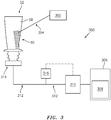
FIG. 3 illustrates a block diagram of a drilling apparatus in accordance with one or more embodiments of the present disclosure. -
FIG. 4 illustrates a block diagram of a drilling apparatus in accordance with one or more embodiments of the present disclosure. -
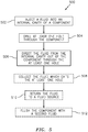
FIG. 5 illustrates a flowchart depicting a method for forming a hollow component in accordance with one or more embodiments of the present disclosure. -
FIG. 6A illustrates a cross-sectional view of the component ofFIG. 2A taken along line 6-6 in accordance with one or more embodiments of the present disclosure. -
FIG. 6B illustrates a cross-sectional view of the component ofFIG. 2A taken along line 6-6 in accordance with one or more embodiments of the present disclosure. - It is noted that various connections are set forth between elements in the following description and in the drawings. It is noted that these connections are general and, unless specified otherwise, may be direct or indirect and that this specification is not intended to be limiting in this respect. A coupling between two or more entities may refer to a direct connection or an indirect connection. An indirect connection may incorporate one or more intervening entities. It is further noted that various method or process steps for embodiments of the present disclosure are described in the following description and drawings. The description may present the method and/or process steps as a particular sequence. However, to the extent that the method or process does not rely on the particular order of steps set forth herein, the method or process should not be limited to the particular sequence of steps described. As one of ordinary skill in the art would appreciate, other sequences of steps may be possible. Therefore, the particular order of the steps set forth in the description should not be construed as a limitation.
- Referring to
FIG. 1 , an exemplarygas turbine engine 10 is schematically illustrated. Thegas turbine engine 10 is disclosed herein as a two-spool turbofan engine that generally includes afan section 12, acompressor section 14, acombustor section 16, and aturbine section 18. Thefan section 12 drives air along abypass flowpath 20 while thecompressor section 14 drives air along acore flowpath 22 for compression and communication into thecombustor section 16 and then expansion through theturbine section 18. Although depicted as a turbofan gas turbine engine in the disclosed non-limiting embodiments, it should be understood that the concepts described herein are not limited to use with turbofans as the teachings may be applied to other types of turbine engines including those with three-spool architectures. - The
gas turbine engine 10 generally includes a low-pressure spool 24 and a high-pressure spool 26 mounted for rotation about alongitudinal centerline 28 of thegas turbine engine 10 relative to an enginestatic structure 30 via one ormore bearing systems 32. It should be understood that various bearingsystems 32 at various locations may alternatively or additionally be provided. - The low-
pressure spool 24 generally includes afirst shaft 34 that interconnects afan 36, a low-pressure compressor 38, and a low-pressure turbine 40. Thefirst shaft 34 is connected to thefan 36 through a gear assembly of a fandrive gear system 42 to drive thefan 36 at a lower speed than the low-pressure spool 24. The high-pressure spool 26 generally includes asecond shaft 44 that interconnects a high-pressure compressor 46 and a high-pressure turbine 48. It is to be understood that "low pressure" and "high pressure" or variations thereof as used herein are relative terms indicating that the high pressure is greater than the low pressure. Anannular combustor 50 is disposed between the high-pressure compressor 46 and the high-pressure turbine 48 along thelongitudinal centerline 28. Thefirst shaft 34 and thesecond shaft 44 are concentric and rotate via the one ormore bearing systems 32 about thelongitudinal centerline 28 which is collinear with respective longitudinal centerlines of the first andsecond shafts - Airflow along the
core flowpath 22 is compressed by the low-pressure compressor 38, then the high-pressure compressor 46, mixed and burned with fuel in thecombustor 50, and then expanded over the high-pressure turbine 48 and the low-pressure turbine 40. The low-pressure turbine 40 and the high-pressure turbine 48 rotationally drive the low-pressure spool 24 and the high-pressure spool 26, respectively, in response to the expansion. - Referring to
FIGS. 2A and2B , thegas turbine engine 10 may include one ormore components 52 which may be configured as hollow castings. For example, as illustrated inFIG. 2A , thecomponent 52 may be an airfoil configured for use in thecompressor section 14 and/or theturbine section 18 of the gas turbine engine. However, as will be understood from the present disclosure, thecomponent 52 may be any suitablegas turbine engine 10 component requiring the drilling of holes therethrough, such as, but not limited to, airfoils, vanes, combustor wall assembly components, etc. - The
component 52 includes acomponent body 54 defining one or moreinternal cavities 56. Thecomponent body 54 includes anexternal wall 64 having anexternal surface 58 and aninternal surface 66. A plurality of holes 60 (e.g., air cooling holes) are formed through thecomponent body 54 of thecomponent 52 between theinternal cavity 56 and theexternal surface 58. The plurality ofholes 60 may be formed through thecomponent body 54, for example, by drilling subsequent to formation of thecomponent body 54. For example, laser drilling of the plurality ofholes 60 may be used to quickly produce hundreds or thousands of holes with a high degree of accuracy. However, thecomponent body 54 may be susceptible to damage from back strikes during laser drilling of the plurality ofholes 60. A back strike is an event which occurs when, for example, a drill bit, laser, EDM electrode, machining process/component, etc. passes through thecomponent body 54 from theexternal surface 58, into theinternal cavity 56, and contacts aninternal wall 62 of thecomponent 52 or aninternal surface 66 of theexternal wall 64 of thecomponent 52, opposite the hole being drilled, potentially causing damage to theinternal wall 62 or theinternal surface 66 of the external wall 64 (see, e.g.,FIG. 2B illustrating exemplaryback strike locations 68 caused by, for example, a laser beam 304). - Referring to
FIGS. 3 and4 , a block diagram of adrilling apparatus 300 is illustrated. Thedrilling apparatus 300 includes alaser generator 302 configured to apply thelaser beam 304 to thecomponent 52 for drilling the plurality ofholes 60 through thecomponent body 54 from theexternal surface 58 to theinternal cavity 56. In various embodiments, thelaser generator 302 is configured to move in one or more of an x-, a y-, and a z-direction, rotate, and/or tilt relative to thecomponent 52 so as to form each hole of the plurality ofholes 60 in the desired location and with the desired orientation. - The
drilling apparatus 300 includes afluid source 306 configured to contain afluid 308. Apump 310 is in fluid communication with thefluid source 306 and theinternal cavity 56 of thecomponent 52 via one ormore conduits 312. Thepump 310 is configured to inject the fluid 308 into theinternal cavity 56 of thecomponent 52 so as to achieve a pressure of the fluid 308 within theinternal cavity 56 that is greater than an ambient pressure (i.e., a pressure external to thecomponent 52, e.g., atmospheric pressure). As a result of the pressure of the fluid 308 within theinternal cavity 56 being greater than ambient pressure, the fluid 308 may directed from theinternal cavity 56 and through the plurality ofholes 60, as the plurality ofholes 60 are formed, so as to exit thecomponent 52 via the plurality ofholes 60. In various embodiments, aseal 314 may be used to fluidly couple thefluid source 306, pump 310, andconduits 312 to theinternal cavity 56 of thecomponent 52 and to minimize or eliminate any leakage offluid 308. - The
drilling apparatus 300 may include one ormore sensors 316 disposed in theconduit 312 between thecomponent 52 and thepump 310. The one ormore sensors 316 may include, for example, fluid pressure sensors, fluid flow sensors, fluid temperature sensors, etc. The one ormore sensors 316 may be in signal communication with thepump 310. Accordingly, thepump 310 may be, for example, a variable flow pump configured to control a flow rate of the fluid 308 injected into theinternal cavity 56 of thecomponent 52 based on an output of the one ormore sensors 316. In various embodiments, thepump 310 may include one or more valves configured to control the flow rate of the fluid 308 injected into theinternal cavity 56 of thecomponent 52. - In various embodiments, the
drilling apparatus 300 may include acollector 318 configured to collect the fluid 308 which exits thecomponent 52 via the plurality ofholes 60. For example, thecollector 318 may be disposed underneath thecomponent 52 such thatfluid 308 exiting thecomponent 52 via the plurality ofholes 60 may fall into thecollector 318. Thecollector 318 may be in fluid communication with thefluid source 306 via one ormore conduits 320. Accordingly, fluid 308 which exits thecomponent 52 via the plurality ofholes 52 may be returned to thefluid source 306 and again injected into theinternal cavity 56 of thecomponent 52 by thepump 310. In various embodiments, the drilling apparatus may include afilter 322 disposed between and in fluid communication with thecollector 318 and thefluid source 306 to filter impurities (e.g., recast material formed during laser drilling of the component 52) from thefluid 308. In various embodiments, - Referring to
FIGS. 2-6 , amethod 500 for forming a hollow component (e.g., the component 52) is disclosed. InStep 502, thepump 310 injects the fluid 308 from thefluid source 306 into theinternal cavity 56 of thecomponent 52 to achieve a pressure of the fluid 308 within theinternal cavity 56 that is greater than the ambient pressure external to thecomponent 52. - In
Step 504, thelaser generator 302 drills the plurality ofholes 60 through thecomponent 52 from theexternal surface 58 of thecomponent 52 to theinternal cavity 56 by applying thelaser beam 304 to thecomponent 52. The fluid 308 present in theinternal cavity 56 may attenuate thelaser beam 304 as it enters theinternal cavity 56, thereby preventing or reducing damage to theinternal wall 62 of thecomponent 52 by preventing the back strike or reducing the energy density or concentration of thelaser beam 304 such that thelaser beam 304 does not damage theinternal wall 62. - In
Step 506, the fluid 308 is directed from theinternal cavity 56 of thecomponent 52 through the plurality ofholes 60, as a result of the pressure of the fluid 308 in theinternal cavity 56 greater than the ambient pressure, so as to exit thecomponent 52 via the plurality ofholes 60. As a result of the positive pressure of the fluid 308 within theinternal cavity 56 relative to ambient pressure, flow of the fluid 308 through a hole of the plurality ofholes 60 may begin immediately upon completion of the hole from theexternal surface 58 to theinternal cavity 56. The fluid 308 may, therefore, immediately provide cooling to the material of thecomponent body 54 surrounding the hole and may cause molten material of thecomponent body 54, formed during laser drilling, to solidify. Continued flow of the fluid 308 through the plurality ofholes 60 and, in various embodiments, down theexternal surface 58 of thecomponent 52, during drilling, may additionally provide cooling to thecomponent body 54 such that thecomponent body 54 can accommodate a faster rate of laser drilling without experiencing an adverse increase in temperature. Directing the fluid 308 out of theinternal cavity 56 through the plurality ofholes 60 may allow recast material (e.g., loose material of thecomponent body 54 formed during laser drilling) and other debris to be flushed from thecomponent 52. Directing the fluid 308 out of theinternal cavity 56 through the plurality ofholes 60 may also cause any air trapped within theinternal cavity 56 to be flushed from thecomponent 52 via the plurality ofholes 60. Air trapped within theinternal cavity 56 may prevent attenuation of alaser beam 304 entering theinternal cavity 56 by causing the fluid 308 to be locally displaced. Accordingly, flushing trapped air from theinternal cavity 56 by directing the fluid 308 to exit theinternal cavity 56 via the plurality ofholes 60 may further reduce the likelihood of damage to theinternal wall 62 as a result of a back strike. - In various embodiments, drilling the plurality of
holes 60, as discussed above with respect to Step 504, may include sequentially drilling each hole of the plurality ofholes 60 progressively from a first position of thecomponent 52 to a second position of thecomponent 52 which is higher than the first position, relative to a gravitational field. As a result, fluid 308 exiting the plurality ofholes 60 orfluid 308 disposed on theexternal surface 58 of thecomponent 52 may not interfere with the laser drilling of subsequent holes of the plurality of holes which may be formed at a higher position relative to previously drilled holes. - In various embodiments, injecting the fluid 308 into the
internal cavity 56 of thecomponent 52, as discussed above with respect to Step 502, may include controlling a flow rate of the fluid 308, with thepump 310, from thefluid source 306 to thecomponent 52. For example, thepump 310, may maintain a predetermined pressure of the fluid 308 within theinternal cavity 56 of thecomponent 52 as the plurality ofholes 60 are sequentially drilled. Thepump 310 may maintain the predetermined pressure of the fluid 308 within theinternal cavity 56 based on, for example, the output of the one ormore sensors 316. For example, thepump 310 may maintain a predetermined pressure of the fluid 308 within theinternal cavity 56 which is greater than ambient pressure. In various embodiments, thepump 310 may maintain a predetermined pressure of the fluid 308 within the internal cavity which is at least one pound per square inch (psi) (6.9 kPa) greater than the ambient pressure. Accordingly, as the number of holes in the plurality ofholes 60 increases, thepump 310 may increase the rate of flow of the fluid 308 injected into theinternal cavity 56 in order to maintain the predetermined pressure of the fluid 308 within the cavity (e.g., to compensate for the increasing number of holes of the plurality of holes 60). The predetermined pressure may be determined based on one or more factors, for example, a height of thecomponent 52, a desired amount of cooling or flushing to be provided to thecomponent 52, or a velocity of the fluid 308 exiting thecomponent 52 via the plurality ofholes 60. - In various embodiments, the
method 500 may include collecting the fluid 308 exiting thecomponent 52 via the plurality ofholes 60 with thecollector 318 inStep 508. InStep 510, the fluid 308 collected by thecollector 318 may be returned to thefluid source 306 for reuse by thepump 310 inStep 502. In various embodiments, returning the collected fluid to thefluid source 306 may include passing the fluid 308 through thefilter 322 to remove any recast material or other debris from thecomponent 52 prior to reintroducing the fluid 308 to thefluid source 306. - The fluid 308 may be, for example, a liquid configured to absorb or scatter the
laser beam 304 upon entry of thelaser beam 304 into theinternal cavity 56 of thecomponent 52. For example, in various embodiments, the fluid 308 may be water. In various other embodiments, the fluid 308 may include one or more dyes configured to improve the laser energy attenuation effectiveness of thefluid 308. The dye may be an opaque dye and may be organic/carbon based (e.g., carbon black) such that the dye can be removed from thecomponent 52 during a burnout cycle. - In various embodiments, the
method 500 may include flushing thecomponent 52 subsequent to laser drilling the plurality ofholes 60 through thecomponent 52, inStep 512. In various embodiments, flushing thecomponent 52 may be performed with asecond fluid 324 which is different than the fluid 308. Flushing thecomponent 52 with thesecond fluid 324 may allow dye, recast material, or debris to be removed from thecomponent 52 after the laser drilling process has been completed. In various embodiments, flushing thecomponent 52 may include supplying thesecond fluid 324 to theinternal cavity 56 of thecomponent 52 and directing thesecond fluid 324 out of thecomponent 52 through the plurality of holes 60 (see, e.g.,FIG. 6A ). Alternatively, in various other embodiments, flushing thecomponent 52 may include supplying thesecond fluid 324 to theexternal surface 58 of thecomponent 52 and directing thesecond fluid 324 into theinternal cavity 56 of thecomponent 52 through the plurality ofholes 60 and subsequently out of the component 52 (see, e.g.,FIG. 6B ). In various embodiments, thesecond fluid 324 used for flushing thecomponent 52 may be collected in a manner similar to that described above with respect toSteps - While various aspects of the present disclosure have been disclosed, it will be apparent to those of ordinary skill in the art that many more embodiments and implementations are possible within the scope of the present disclosure. For example, the present disclosure as described herein includes several aspects and embodiments that include particular features. Although these particular features may be described individually, it is within the scope of the present disclosure that some or all of these features may be combined with any one of the aspects and remain within the scope of the present disclosure. References to "various embodiments," "one embodiment," "an embodiment," "an example embodiment," etc., indicate that the embodiment described may include a particular feature, structure, or characteristic, but every embodiment may not necessarily include the particular feature, structure, or characteristic. Moreover, such phrases are not necessarily referring to the same embodiment. Further, when a particular feature, structure, or characteristic is described in connection with an embodiment, it is submitted that it is within the knowledge of one skilled in the art to effect such feature, structure, or characteristic in connection with other embodiments whether or not explicitly described. Accordingly, the present disclosure is not to be restricted except in light of the attached claims and their equivalents.
Claims (15)
- A method for forming a hollow component (52), the method comprising:injecting a fluid (308) into an internal cavity (56) of the hollow component (52) to achieve a pressure of the fluid (308) within the internal cavity (56) that is greater than an ambient pressure;drilling at least one hole (60) through the hollow component (52) from an external surface (58) of the hollow component (52) to the internal cavity (56) by applying a laser beam (304) to the hollow component (52) with a laser generator (302); anddirecting the fluid (308) from the internal cavity (56) and through the at least one hole (60) so as to exit the hollow component (52) via the at least one hole (60).
- The method of claim 1, wherein the at least one hole (60) comprises a plurality of holes (60).
- The method of claim 2, wherein drilling the plurality of holes (60) through the hollow component (52) comprises sequentially drilling each hole (60) of the plurality of holes (60) progressively from a first position of the hollow component (52) to a second position of the hollow component (52), the second position higher than the first position.
- The method of any preceding claim, wherein injecting the fluid (308) into the internal cavity (56) of the hollow component (52) comprises controlling a flow rate of the fluid (308) from a fluid source (306) to the hollow component (52).
- The method of claim 3 or claim 4 as dependent on claim 3, further comprising maintaining a predetermined fluid pressure within the internal cavity (56) of the hollow component (52) as the plurality of holes (60) are sequentially drilled.
- The method of claim 2 or of any of claims 3 to 5 as dependent on claim 2, further comprising collecting the fluid (308) which exits the plurality of holes (60).
- The method of claim 6, further comprising returning the collected fluid (308) to the fluid source (306), wherein returning the collected fluid (308) to the fluid source (306) optionally includes passing the fluid (308) through a filter (322).
- The method of any preceding claim, further comprising fluidly coupling the hollow component (52) to the fluid source (306) with a seal (314).
- A system comprising:a hollow component (52) comprising an external surface (58) and an internal cavity (56), the hollow component (52) comprising at least one hole (60) extending through the hollow component (52) between the external surface (58) and the internal cavity (56); anda drilling apparatus (300) comprising:a laser generator (302) configured to apply a laser beam (304) to the hollow component (52);a fluid source (306) containing a fluid (308); anda pump (310) in fluid communication with the fluid source (306) and the internal cavity (56) of the hollow component (52), the pump (310) configured to inject the fluid (308) into the internal cavity (56) of the hollow component (52) so as to achieve a pressure of the fluid (308) within the internal cavity (56) that is greater than an ambient pressure.
- The system of claim 9, wherein the at least one hole (60) comprises a plurality of holes (60).
- The system of claim 9 or 10, wherein the drilling apparatus (300) further comprises a collector (318) disposed underneath the hollow component (52), the collector (318) fluidly coupled to the fluid source (306), wherein the drilling apparatus (300) optionally further comprises a filter (322) fluidly coupling the collector (318) and the fluid source (306).
- The system of any of claims 9 to 11, wherein the drilling apparatus (300) further comprises a sensor (316) configured to determine the pressure of the fluid (308) in the internal cavity (56) of the hollow component (52), and/or wherein the pump (310) is configured to maintain a predetermined fluid pressure within the internal cavity (56) of the hollow component (56).
- The method of any of claims 1 to 8 or system of any of claims 9 to 12, wherein the fluid (308) comprises water and optionally a dye.
- The method of claim 2 or any of claims 2 to 8 or 13 as dependent on claim 2, further comprising flushing the hollow component (52) with a second fluid (324), different than the fluid (308), subsequent to drilling the plurality of holes (60) through the hollow component (52).
- A method for forming a hollow component (52), the method comprising:injecting a fluid (308) into an internal cavity (56) of the hollow component (52) to achieve a pressure of the fluid (308) within the internal cavity (56) that is greater than an ambient pressure;sequentially drilling a plurality of holes (60) through the hollow component (52) from an external surface (58) of the hollow component (52) to the internal cavity (56) by applying a laser beam (304) to the hollow component (52) with a laser generator (302), the plurality of holes (60) drilled progressively from a first position of the hollow component (52) to a second position of the hollow component (52), the second position higher than the first position;directing the fluid (308) from the internal cavity (56) and through the plurality of holes (60) so as to exit the hollow component (52) via the plurality of holes (60); andcontrolling a flow rate of the fluid (308) from a fluid source (306) to the hollow component (52) so as to maintain a predetermined fluid pressure within the internal cavity (56) of the hollow component (52) as the plurality of holes (60) are sequentially drilled.
Applications Claiming Priority (1)
| Application Number | Priority Date | Filing Date | Title |
|---|---|---|---|
| US16/746,246 US12370630B2 (en) | 2020-01-17 | 2020-01-17 | Method and system for preventing back strikes when laser drilling hollow parts |
Publications (2)
| Publication Number | Publication Date |
|---|---|
| EP3851241A1 true EP3851241A1 (en) | 2021-07-21 |
| EP3851241B1 EP3851241B1 (en) | 2025-03-12 |
Family
ID=74184424
Family Applications (1)
| Application Number | Title | Priority Date | Filing Date |
|---|---|---|---|
| EP21151529.1A Active EP3851241B1 (en) | 2020-01-17 | 2021-01-14 | Method for preventing back strikes when laser drilling hollow parts |
Country Status (2)
| Country | Link |
|---|---|
| US (1) | US12370630B2 (en) |
| EP (1) | EP3851241B1 (en) |
Families Citing this family (2)
| Publication number | Priority date | Publication date | Assignee | Title |
|---|---|---|---|---|
| US11524350B1 (en) | 2021-10-04 | 2022-12-13 | General Electric Company | Backwall strike braze repair |
| GB2632332A (en) * | 2023-08-04 | 2025-02-05 | Siemens Energy Global Gmbh & Co Kg | Double wall component with hole |
Citations (4)
| Publication number | Priority date | Publication date | Assignee | Title |
|---|---|---|---|---|
| WO1989003274A1 (en) * | 1987-10-14 | 1989-04-20 | Akademiet For De Tekniske Videnskaber, Svejsecentr | Method and application of laser drilling |
| US5049722A (en) * | 1989-09-16 | 1991-09-17 | Rolls-Royce Plc | Laser barrier material and method of laser drilling |
| US20130146570A1 (en) * | 2011-12-07 | 2013-06-13 | General Atomics | Methods and systems for use in laser machining |
| DE102013218196A1 (en) * | 2013-09-11 | 2015-03-12 | Robert Bosch Gmbh | Method for laser drilling a component |
Family Cites Families (15)
| Publication number | Priority date | Publication date | Assignee | Title |
|---|---|---|---|---|
| GB2249279B (en) | 1990-10-17 | 1994-01-05 | Rolls Royce Plc | Improvements in or relating to drilling turbine blades |
| GB2328894B (en) * | 1997-09-03 | 1999-07-14 | Oxford Lasers Ltd | Laser drilling |
| AU4004099A (en) | 1999-05-18 | 2000-12-05 | United States Enrichment Corporation | Method and apparatus for laser machining workpieces with liquid backing |
| US20030201087A1 (en) | 2002-04-25 | 2003-10-30 | Devine Robert H. | Way to manufacture inserts for steam cooled hot gas path components |
| US6696666B2 (en) | 2002-07-03 | 2004-02-24 | Scimed Life Systems, Inc. | Tubular cutting process and system |
| EP1598140A1 (en) * | 2004-05-19 | 2005-11-23 | Synova S.A. | Laser machining |
| GB201115354D0 (en) * | 2011-09-06 | 2011-10-19 | Rolls Royce Plc | Method of drilling through a wall of a hollow component |
| US9238265B2 (en) | 2012-09-27 | 2016-01-19 | General Electric Company | Backstrike protection during machining of cooling features |
| DE102013212665B4 (en) * | 2013-06-28 | 2015-06-25 | Laser Zentrum Hannover E.V. | Method for laser drilling or laser cutting a workpiece |
| US9662743B2 (en) | 2014-01-27 | 2017-05-30 | General Electric Company | Method for drilling a hole in an airfoil |
| US9468991B2 (en) | 2014-01-27 | 2016-10-18 | General Electric Company | Method determining hole completion |
| US9770785B2 (en) * | 2014-11-18 | 2017-09-26 | General Electric Company | System and method for forming a cooling hole in an airfoil |
| CN104827194A (en) | 2015-05-13 | 2015-08-12 | 西安交通大学 | Method for rear wall protection in laser processing of turbine blade by using water and silicon dioxide |
| DE102015209261A1 (en) * | 2015-05-21 | 2016-11-24 | Robert Bosch Gmbh | Method for laser drilling or laser cutting a workpiece and system for laser drilling or laser cutting |
| DE102017116943B4 (en) | 2017-07-26 | 2019-04-11 | Laser Zentrum Hannover E.V. | Method for laser drilling or laser cutting a workpiece |
-
2020
- 2020-01-17 US US16/746,246 patent/US12370630B2/en active Active
-
2021
- 2021-01-14 EP EP21151529.1A patent/EP3851241B1/en active Active
Patent Citations (4)
| Publication number | Priority date | Publication date | Assignee | Title |
|---|---|---|---|---|
| WO1989003274A1 (en) * | 1987-10-14 | 1989-04-20 | Akademiet For De Tekniske Videnskaber, Svejsecentr | Method and application of laser drilling |
| US5049722A (en) * | 1989-09-16 | 1991-09-17 | Rolls-Royce Plc | Laser barrier material and method of laser drilling |
| US20130146570A1 (en) * | 2011-12-07 | 2013-06-13 | General Atomics | Methods and systems for use in laser machining |
| DE102013218196A1 (en) * | 2013-09-11 | 2015-03-12 | Robert Bosch Gmbh | Method for laser drilling a component |
Also Published As
| Publication number | Publication date |
|---|---|
| US20210220950A1 (en) | 2021-07-22 |
| EP3851241B1 (en) | 2025-03-12 |
| US12370630B2 (en) | 2025-07-29 |
Similar Documents
| Publication | Publication Date | Title |
|---|---|---|
| EP3851241B1 (en) | Method for preventing back strikes when laser drilling hollow parts | |
| EP4201580A1 (en) | Fabrication of cooling holes using laser machining and ultrasonic machining | |
| EP3246523B1 (en) | Cooled blade outer air seal | |
| US5914060A (en) | Method of laser drilling an airfoil | |
| EP2971539B1 (en) | Method of non-line of sight electro discharge machining | |
| US5928534A (en) | Method for reducing void volumes in cavities for laser drilling | |
| EP2971702A1 (en) | Bleed valve assembly | |
| US7185662B2 (en) | Methods of preparing, cleaning and repairing article and article repaired | |
| US11773726B2 (en) | Angled tip rods | |
| US20160221124A1 (en) | Method For Disposing A Blocking Material | |
| US10226814B2 (en) | Cast component having corner radius to reduce recrystallization | |
| US9862057B2 (en) | Vacuum degassing laser-blocking material system and process | |
| EP3453971B1 (en) | Method to produce a heat shield panel assembly | |
| EP3453972B1 (en) | Method to produce jet engine combustor heat shield panels assembly | |
| US20230070114A1 (en) | Multi-step method for machining blind ope1ning in ceramic component | |
| US10919116B2 (en) | Installation of laser vent holes into vertical walls of cavity-back airfoils | |
| US10808571B2 (en) | Gaspath component including minicore plenums | |
| EP3926142B1 (en) | Fan blade for a gas turbine engine, gas turbine engine and method of forming a fan blade. | |
| EP1704933B1 (en) | Methods of preparing, cleaning and repairing an article | |
| EP4137271A1 (en) | Method and system for drilling ceramic material | |
| EP4166760A1 (en) | Angled tip rods | |
| EP3550110A1 (en) | Airfoil having leading edge cooling scheme with backstrike compensation |
Legal Events
| Date | Code | Title | Description |
|---|---|---|---|
| PUAI | Public reference made under article 153(3) epc to a published international application that has entered the european phase |
Free format text: ORIGINAL CODE: 0009012 |
|
| STAA | Information on the status of an ep patent application or granted ep patent |
Free format text: STATUS: THE APPLICATION HAS BEEN PUBLISHED |
|
| AK | Designated contracting states |
Kind code of ref document: A1 Designated state(s): AL AT BE BG CH CY CZ DE DK EE ES FI FR GB GR HR HU IE IS IT LI LT LU LV MC MK MT NL NO PL PT RO RS SE SI SK SM TR |
|
| STAA | Information on the status of an ep patent application or granted ep patent |
Free format text: STATUS: REQUEST FOR EXAMINATION WAS MADE |
|
| 17P | Request for examination filed |
Effective date: 20220121 |
|
| RBV | Designated contracting states (corrected) |
Designated state(s): AL AT BE BG CH CY CZ DE DK EE ES FI FR GB GR HR HU IE IS IT LI LT LU LV MC MK MT NL NO PL PT RO RS SE SI SK SM TR |
|
| RAP3 | Party data changed (applicant data changed or rights of an application transferred) |
Owner name: RTX CORPORATION |
|
| GRAP | Despatch of communication of intention to grant a patent |
Free format text: ORIGINAL CODE: EPIDOSNIGR1 |
|
| STAA | Information on the status of an ep patent application or granted ep patent |
Free format text: STATUS: GRANT OF PATENT IS INTENDED |
|
| RIC1 | Information provided on ipc code assigned before grant |
Ipc: F01D 5/18 20060101ALN20240927BHEP Ipc: B23K 101/00 20060101ALI20240927BHEP Ipc: B23K 26/382 20140101AFI20240927BHEP |
|
| INTG | Intention to grant announced |
Effective date: 20241010 |
|
| GRAS | Grant fee paid |
Free format text: ORIGINAL CODE: EPIDOSNIGR3 |
|
| GRAA | (expected) grant |
Free format text: ORIGINAL CODE: 0009210 |
|
| STAA | Information on the status of an ep patent application or granted ep patent |
Free format text: STATUS: THE PATENT HAS BEEN GRANTED |
|
| AK | Designated contracting states |
Kind code of ref document: B1 Designated state(s): AL AT BE BG CH CY CZ DE DK EE ES FI FR GB GR HR HU IE IS IT LI LT LU LV MC MK MT NL NO PL PT RO RS SE SI SK SM TR |
|
| REG | Reference to a national code |
Ref country code: GB Ref legal event code: FG4D |
|
| REG | Reference to a national code |
Ref country code: CH Ref legal event code: EP |
|
| REG | Reference to a national code |
Ref country code: DE Ref legal event code: R096 Ref document number: 602021027366 Country of ref document: DE |
|
| REG | Reference to a national code |
Ref country code: IE Ref legal event code: FG4D |
|
| PG25 | Lapsed in a contracting state [announced via postgrant information from national office to epo] |
Ref country code: RS Free format text: LAPSE BECAUSE OF FAILURE TO SUBMIT A TRANSLATION OF THE DESCRIPTION OR TO PAY THE FEE WITHIN THE PRESCRIBED TIME-LIMIT Effective date: 20250612 |
|
| PG25 | Lapsed in a contracting state [announced via postgrant information from national office to epo] |
Ref country code: FI Free format text: LAPSE BECAUSE OF FAILURE TO SUBMIT A TRANSLATION OF THE DESCRIPTION OR TO PAY THE FEE WITHIN THE PRESCRIBED TIME-LIMIT Effective date: 20250312 |
|
| PG25 | Lapsed in a contracting state [announced via postgrant information from national office to epo] |
Ref country code: ES Free format text: LAPSE BECAUSE OF FAILURE TO SUBMIT A TRANSLATION OF THE DESCRIPTION OR TO PAY THE FEE WITHIN THE PRESCRIBED TIME-LIMIT Effective date: 20250312 |
|
| REG | Reference to a national code |
Ref country code: LT Ref legal event code: MG9D |
|
| PG25 | Lapsed in a contracting state [announced via postgrant information from national office to epo] |
Ref country code: NO Free format text: LAPSE BECAUSE OF FAILURE TO SUBMIT A TRANSLATION OF THE DESCRIPTION OR TO PAY THE FEE WITHIN THE PRESCRIBED TIME-LIMIT Effective date: 20250612 |
|
| PG25 | Lapsed in a contracting state [announced via postgrant information from national office to epo] |
Ref country code: HR Free format text: LAPSE BECAUSE OF FAILURE TO SUBMIT A TRANSLATION OF THE DESCRIPTION OR TO PAY THE FEE WITHIN THE PRESCRIBED TIME-LIMIT Effective date: 20250312 |
|
| REG | Reference to a national code |
Ref country code: NL Ref legal event code: MP Effective date: 20250312 |
|
| PG25 | Lapsed in a contracting state [announced via postgrant information from national office to epo] |
Ref country code: LV Free format text: LAPSE BECAUSE OF FAILURE TO SUBMIT A TRANSLATION OF THE DESCRIPTION OR TO PAY THE FEE WITHIN THE PRESCRIBED TIME-LIMIT Effective date: 20250312 |
|
| PG25 | Lapsed in a contracting state [announced via postgrant information from national office to epo] |
Ref country code: BG Free format text: LAPSE BECAUSE OF FAILURE TO SUBMIT A TRANSLATION OF THE DESCRIPTION OR TO PAY THE FEE WITHIN THE PRESCRIBED TIME-LIMIT Effective date: 20250312 Ref country code: GR Free format text: LAPSE BECAUSE OF FAILURE TO SUBMIT A TRANSLATION OF THE DESCRIPTION OR TO PAY THE FEE WITHIN THE PRESCRIBED TIME-LIMIT Effective date: 20250613 |
|
| REG | Reference to a national code |
Ref country code: AT Ref legal event code: MK05 Ref document number: 1774616 Country of ref document: AT Kind code of ref document: T Effective date: 20250312 |
|
| PG25 | Lapsed in a contracting state [announced via postgrant information from national office to epo] |
Ref country code: NL Free format text: LAPSE BECAUSE OF FAILURE TO SUBMIT A TRANSLATION OF THE DESCRIPTION OR TO PAY THE FEE WITHIN THE PRESCRIBED TIME-LIMIT Effective date: 20250312 |
|
| PG25 | Lapsed in a contracting state [announced via postgrant information from national office to epo] |
Ref country code: SE Free format text: LAPSE BECAUSE OF FAILURE TO SUBMIT A TRANSLATION OF THE DESCRIPTION OR TO PAY THE FEE WITHIN THE PRESCRIBED TIME-LIMIT Effective date: 20250312 |
|
| PG25 | Lapsed in a contracting state [announced via postgrant information from national office to epo] |
Ref country code: SM Free format text: LAPSE BECAUSE OF FAILURE TO SUBMIT A TRANSLATION OF THE DESCRIPTION OR TO PAY THE FEE WITHIN THE PRESCRIBED TIME-LIMIT Effective date: 20250312 |
|
| PG25 | Lapsed in a contracting state [announced via postgrant information from national office to epo] |
Ref country code: PT Free format text: LAPSE BECAUSE OF FAILURE TO SUBMIT A TRANSLATION OF THE DESCRIPTION OR TO PAY THE FEE WITHIN THE PRESCRIBED TIME-LIMIT Effective date: 20250714 |
|
| PG25 | Lapsed in a contracting state [announced via postgrant information from national office to epo] |
Ref country code: IT Free format text: LAPSE BECAUSE OF FAILURE TO SUBMIT A TRANSLATION OF THE DESCRIPTION OR TO PAY THE FEE WITHIN THE PRESCRIBED TIME-LIMIT Effective date: 20250312 Ref country code: PL Free format text: LAPSE BECAUSE OF FAILURE TO SUBMIT A TRANSLATION OF THE DESCRIPTION OR TO PAY THE FEE WITHIN THE PRESCRIBED TIME-LIMIT Effective date: 20250312 |
|
| PG25 | Lapsed in a contracting state [announced via postgrant information from national office to epo] |
Ref country code: AT Free format text: LAPSE BECAUSE OF FAILURE TO SUBMIT A TRANSLATION OF THE DESCRIPTION OR TO PAY THE FEE WITHIN THE PRESCRIBED TIME-LIMIT Effective date: 20250312 |
|
| PG25 | Lapsed in a contracting state [announced via postgrant information from national office to epo] |
Ref country code: EE Free format text: LAPSE BECAUSE OF FAILURE TO SUBMIT A TRANSLATION OF THE DESCRIPTION OR TO PAY THE FEE WITHIN THE PRESCRIBED TIME-LIMIT Effective date: 20250312 Ref country code: CZ Free format text: LAPSE BECAUSE OF FAILURE TO SUBMIT A TRANSLATION OF THE DESCRIPTION OR TO PAY THE FEE WITHIN THE PRESCRIBED TIME-LIMIT Effective date: 20250312 |
|
| PG25 | Lapsed in a contracting state [announced via postgrant information from national office to epo] |
Ref country code: RO Free format text: LAPSE BECAUSE OF FAILURE TO SUBMIT A TRANSLATION OF THE DESCRIPTION OR TO PAY THE FEE WITHIN THE PRESCRIBED TIME-LIMIT Effective date: 20250312 |
|
| PG25 | Lapsed in a contracting state [announced via postgrant information from national office to epo] |
Ref country code: SK Free format text: LAPSE BECAUSE OF FAILURE TO SUBMIT A TRANSLATION OF THE DESCRIPTION OR TO PAY THE FEE WITHIN THE PRESCRIBED TIME-LIMIT Effective date: 20250312 |
|
| PG25 | Lapsed in a contracting state [announced via postgrant information from national office to epo] |
Ref country code: IS Free format text: LAPSE BECAUSE OF FAILURE TO SUBMIT A TRANSLATION OF THE DESCRIPTION OR TO PAY THE FEE WITHIN THE PRESCRIBED TIME-LIMIT Effective date: 20250712 |
|
| REG | Reference to a national code |
Ref country code: DE Ref legal event code: R097 Ref document number: 602021027366 Country of ref document: DE |
|
| PGFP | Annual fee paid to national office [announced via postgrant information from national office to epo] |
Ref country code: GB Payment date: 20251220 Year of fee payment: 6 |
|
| PG25 | Lapsed in a contracting state [announced via postgrant information from national office to epo] |
Ref country code: DK Free format text: LAPSE BECAUSE OF FAILURE TO SUBMIT A TRANSLATION OF THE DESCRIPTION OR TO PAY THE FEE WITHIN THE PRESCRIBED TIME-LIMIT Effective date: 20250312 |
|
| PGFP | Annual fee paid to national office [announced via postgrant information from national office to epo] |
Ref country code: FR Payment date: 20251217 Year of fee payment: 6 |
|
| PLBE | No opposition filed within time limit |
Free format text: ORIGINAL CODE: 0009261 |
|
| STAA | Information on the status of an ep patent application or granted ep patent |
Free format text: STATUS: NO OPPOSITION FILED WITHIN TIME LIMIT |
|
| REG | Reference to a national code |
Ref country code: CH Ref legal event code: L10 Free format text: ST27 STATUS EVENT CODE: U-0-0-L10-L00 (AS PROVIDED BY THE NATIONAL OFFICE) Effective date: 20260121 |
|
| 26N | No opposition filed |
Effective date: 20251215 |
|
| PGFP | Annual fee paid to national office [announced via postgrant information from national office to epo] |
Ref country code: DE Payment date: 20251217 Year of fee payment: 6 |