EP3851199A1 - Water outlet assembly and water outlet device - Google Patents
Water outlet assembly and water outlet device Download PDFInfo
- Publication number
- EP3851199A1 EP3851199A1 EP21152093.7A EP21152093A EP3851199A1 EP 3851199 A1 EP3851199 A1 EP 3851199A1 EP 21152093 A EP21152093 A EP 21152093A EP 3851199 A1 EP3851199 A1 EP 3851199A1
- Authority
- EP
- European Patent Office
- Prior art keywords
- water outlet
- water
- hole
- disposed
- jet hole
- Prior art date
- Legal status (The legal status is an assumption and is not a legal conclusion. Google has not performed a legal analysis and makes no representation as to the accuracy of the status listed.)
- Withdrawn
Links
Images




Classifications
-
- B—PERFORMING OPERATIONS; TRANSPORTING
- B05—SPRAYING OR ATOMISING IN GENERAL; APPLYING FLUENT MATERIALS TO SURFACES, IN GENERAL
- B05B—SPRAYING APPARATUS; ATOMISING APPARATUS; NOZZLES
- B05B1/00—Nozzles, spray heads or other outlets, with or without auxiliary devices such as valves, heating means
- B05B1/14—Nozzles, spray heads or other outlets, with or without auxiliary devices such as valves, heating means with multiple outlet openings; with strainers in or outside the outlet opening
- B05B1/18—Roses; Shower heads
-
- B—PERFORMING OPERATIONS; TRANSPORTING
- B05—SPRAYING OR ATOMISING IN GENERAL; APPLYING FLUENT MATERIALS TO SURFACES, IN GENERAL
- B05B—SPRAYING APPARATUS; ATOMISING APPARATUS; NOZZLES
- B05B1/00—Nozzles, spray heads or other outlets, with or without auxiliary devices such as valves, heating means
- B05B1/12—Nozzles, spray heads or other outlets, with or without auxiliary devices such as valves, heating means capable of producing different kinds of discharge, e.g. either jet or spray
-
- B—PERFORMING OPERATIONS; TRANSPORTING
- B05—SPRAYING OR ATOMISING IN GENERAL; APPLYING FLUENT MATERIALS TO SURFACES, IN GENERAL
- B05B—SPRAYING APPARATUS; ATOMISING APPARATUS; NOZZLES
- B05B1/00—Nozzles, spray heads or other outlets, with or without auxiliary devices such as valves, heating means
- B05B1/14—Nozzles, spray heads or other outlets, with or without auxiliary devices such as valves, heating means with multiple outlet openings; with strainers in or outside the outlet opening
- B05B1/18—Roses; Shower heads
- B05B1/185—Roses; Shower heads characterised by their outlet element; Mounting arrangements therefor
-
- B—PERFORMING OPERATIONS; TRANSPORTING
- B05—SPRAYING OR ATOMISING IN GENERAL; APPLYING FLUENT MATERIALS TO SURFACES, IN GENERAL
- B05B—SPRAYING APPARATUS; ATOMISING APPARATUS; NOZZLES
- B05B1/00—Nozzles, spray heads or other outlets, with or without auxiliary devices such as valves, heating means
- B05B1/26—Nozzles, spray heads or other outlets, with or without auxiliary devices such as valves, heating means with means for mechanically breaking-up or deflecting the jet after discharge, e.g. with fixed deflectors; Breaking-up the discharged liquid or other fluent material by impinging jets
- B05B1/262—Nozzles, spray heads or other outlets, with or without auxiliary devices such as valves, heating means with means for mechanically breaking-up or deflecting the jet after discharge, e.g. with fixed deflectors; Breaking-up the discharged liquid or other fluent material by impinging jets with fixed deflectors
-
- B—PERFORMING OPERATIONS; TRANSPORTING
- B05—SPRAYING OR ATOMISING IN GENERAL; APPLYING FLUENT MATERIALS TO SURFACES, IN GENERAL
- B05B—SPRAYING APPARATUS; ATOMISING APPARATUS; NOZZLES
- B05B1/00—Nozzles, spray heads or other outlets, with or without auxiliary devices such as valves, heating means
- B05B1/34—Nozzles, spray heads or other outlets, with or without auxiliary devices such as valves, heating means designed to influence the nature of flow of the liquid or other fluent material, e.g. to produce swirl
- B05B1/3402—Nozzles, spray heads or other outlets, with or without auxiliary devices such as valves, heating means designed to influence the nature of flow of the liquid or other fluent material, e.g. to produce swirl to avoid or reduce turbulence, e.g. with fluid flow straightening means
-
- E—FIXED CONSTRUCTIONS
- E03—WATER SUPPLY; SEWERAGE
- E03C—DOMESTIC PLUMBING INSTALLATIONS FOR FRESH WATER OR WASTE WATER; SINKS
- E03C1/00—Domestic plumbing installations for fresh water or waste water; Sinks
- E03C1/02—Plumbing installations for fresh water
- E03C1/08—Jet regulators or jet guides, e.g. anti-splash devices
- E03C1/086—Jet regulators or jet guides, easily mountable on the outlet of taps
Definitions
- the present disclosure relates to the technical fields of kitchen and bathroom, and in particular relates to a water outlet assembly and a water outlet device.
- a first type of water outlet device comprises an ejector, and the ejector comprises a jet hole.
- the water ejected from the jet hole defines straight water, and the straight water has great impact force.
- a second type of water outlet device comprises a water outlet plate, and the water outlet plate comprises a water outlet hole. Water impacts the water outlet plate, flows out along a periphery of the water outlet hole, and defines a water curtain.
- the above-mentioned two types of water outlet devices merely have single spray patterns, and there is a need for further improvement.
- the present disclosure provides a water outlet assembly and a water outlet device to solve the deficiencies of the water outlet device in the background.
- a water outlet assembly comprises an ejector and a water outlet portion disposed along a water flow direction.
- the ejector comprises a jet hole.
- the water outlet portion comprises a shielding portion and a water outlet hole penetrating the shielding portion.
- An opening of the water outlet hole is enlarged along the water flow direction. Water ejected from the jet hole is divided into an impact portion and a straight portion, the impact portion impacts the shielding portion and flows out along an edge of the water outlet hole to define a water curtain, and the straight portion directly flushes through the water outlet hole to be ejected to define straight water.
- a cross-section of the jet hole comprises a concave area extending outward or a corner area.
- a cross-section of the jet hole defines a plum blossom shape.
- the ejector comprises a through hole, an inner wall of the through hole is convex to define one or more ribs, the through hole defines the jet hole due to the one or more ribs, and the jet hole defines a plum blossom shape structure.
- the opening of the water outlet hole defines a tapered structure with a large lower large end and a small upper end.
- the water outlet hole comprises an upper section and a lower section disposed along the water flow direction.
- An upper end port of the water outlet hole extends downward to define the upper section, a lower peripheral edge of the upper section expands and extends downward and outward to define the lower section, and the lower section defines the tapered structure.
- the water outlet hole comprises a central area overlapped by a top-down projection of the jet hole and a remaining area disposed out of the top-down projection, the straight portion corresponds to the central area, and the remaining area half encompasses the central area to generate a water curtain to define the water curtain disposed in an outer circle and half encompassing the straight water disposed in an inner circle.
- the impact portion impacts the shielding portion and flows downward along an edge of the remaining area of the water outlet hole.
- the edge of the remaining area comprises an arc section, and the impact portion impacts the shielding portion and flows downward at least along the arc section.
- an upper end port of the water outlet hole comprises a substantially W-shaped structure.
- a middle top portion of the substantially W-shaped structure define a central area, and the straight portion directly flushes the central area of the water outlet hole to be ejected.
- the substantially W-shaped structure comprises the central area and a remaining area, and the remaining area half encompasses the central area.
- a plurality of connecting lines are connected together to define a peripheral edge of the upper end port of the water outlet hole, and connection points of the plurality of connecting lines are smoothly disposed.
- a periphery of an upper end port of the water outlet hole comprises a V-shaped section, two curved sections axially symmetrically disposed on two sides of the V-shaped section, and a circular arc section, ends of the two curved sections are connected to two ends of the V-shaped section, the two curved sections and the V-shaped section cooperate to define a substantially W-shaped structure, two ends of the circular arc section are respectively connected to the other ends of the two curved sections, an opening of the circular arc section is disposed opposite to a top angle of the V-shaped section, a portion encompassed by the V-shaped section defines a central area, and the straight portion corresponds to the central area.
- the impact portion flows out along the two curved sections or the two curved sections and the circular arc section.
- the water outlet portion comprises a plurality of water outlet holes
- the jet hole corresponds to the plurality of water outlet holes
- the plurality of water outlet holes are disposed in an annular array, and an axis of the annular array coincides with an axis of the jet hole.
- upper end ports of the plurality of water outlet holes comprise substantially W-shaped structures, and middle top portions of the W-shaped structures face the axis of the annular array.
- a periphery of the shielding portion extends upward to define a lower peripheral wall, and the ejector is disposed in an upper port of the lower peripheral wall.
- the ejector comprises an upper peripheral wall, an upper portion of the upper peripheral wall extends outward to define a convex ring, a middle plate is secured in the upper peripheral wall, the middle plate comprises the jet hole, the upper peripheral wall cooperates with and is disposed in the lower peripheral wall, and the convex ring abuts an end surface of the lower peripheral wall.
- an outer diameter of the middle plate is smaller than a diameter of the shielding portion.
- a water outlet assembly comprises an ejector and a water outlet portion disposed along a water flow direction.
- the ejector comprises a jet hole.
- a cross-section of the jet hole comprises a concave area extending outward or a corner area.
- the water outlet portion comprises a shielding portion and a water outlet hole penetrating the shielding portion.
- the water outlet hole comprises a central area overlapped by a top-down projection of the jet hole and a remaining area disposed out of the top-down projection
- the top-down projection of the jet hole comprises an overlapped portion disposed on the water outlet hole in and a non-overlapped portion disposed on the shielding portion and an outer side of the water outlet hole
- the concave area extending outward or the corner area of the jet hole corresponds to the central area of the water outlet hole.
- a water outlet device comprises a housing portion and the water outlet assembly.
- the housing portion comprises an upper housing and a lower housing, the upper housing is disposed with a connector, the lower housing is secured to the upper housing, a middle cavity in communication with the connector is defined between the upper housing and the lower housing, and the water outlet assembly is secured to the lower housing.
- a fourth technical solution of the present disclosure is as follows.
- a kitchen faucet comprises a faucet body.
- a water outlet port of the faucet body is disposed with the water outlet assembly.
- a fifth technical solution of the present disclosure is as follows.
- a kitchen faucet comprises a faucet body.
- a water outlet port of the faucet body is disposed with the water outlet device.
- the water outlet hole expands outward along the water flow direction.
- the impact portion of the water ejected from the jet hole impacts the shielding portion and flows out along the edge of the water outlet hole to define a water curtain.
- the straight portion directly flushes through the water outlet hole and flows out to be ejected to define straight water.
- the ejected water is divided into two portions. One portion defines the straight water to strengthen the straight impact force, and the other portion cooperates and expands to define a water curtain that can generate particle spray.
- the water curtain and the straight water flow out concurrently to have a good water spray effect.
- the cross section of the jet hole has a concave area extending outward or a corner area.
- the water outlet hole has a central area overlapped by a top-down projection of the jet hole and the remaining area disposed out of the top-down projection.
- the top-down projection of the jet hole comprises the overlapped portion disposed on the water outlet hole and the non-overlapped portion disposed on the shielding portion and an outer side the water outlet hole.
- the concave area extending outward or the corner area of the jet hole corresponds to the center area of the water outlet hole.
- the ejected water is divided into two portions. One portion cooperates with the concave area extending outward or the corner area to define the straight water to improve straight impact force, and the other portion cooperates and expands to define a water curtain. The water curtain and the straight water flow out concurrently, the water spray effect is good.
- the cross section of the jet hole has the concave area extending outward or the corner area to cooperate with the straight portion, and the straight impact force can be more powerful.
- the through hole defines the jet hole due to the ribs, and the jet hole has a plum blossom shape, which is convenient for production and simple in structure.
- housing portion 1 water outlet assembly 2, upper housing 11, lower housing 12, connector 111, middle cavity 13, ejector 21, jet hole 211, rib 212, upper peripheral wall 213, convex ring 214, middle plate 215, water outlet portion 22, shielding portion 221, water outlet hole 222, tapered structure 223, V-shaped section 224, curved section 225, arc section 226, central area 224', remaining area 225', lower peripheral wall 227, straight water 31, and half-encompassing water curtain 32.
- a water outlet device comprises a housing portion 1 and a water outlet assembly 2.
- the housing portion 1 comprises an upper housing 11 and a lower housing 12.
- the upper housing 11 is disposed with a connector 111.
- the lower housing 12 is secured to the upper housing 11, and a middle cavity 13 in communication with the connector is defined between the upper housing 11 and the lower housing 12.
- the water outlet assembly is secured to the lower housing 12 and is in communication with the middle cavity 13.
- the water outlet assembly 2 comprises an ejector 21 and a water outlet portion 22 disposed along a water flow direction.
- the ejector 21 comprises a jet hole 211.
- a cross-section of the jet hole defines a non-circular shape.
- the cross-section of the jet hole 211 defines a plum blossom shape, and a cross-section of the plum blossom shape comprises a plurality of concave areas extending outward (i.e. a corner area).
- figures illustrate six concave areas extending outward, but which are not limited to thereto. As needed, which can illustrate four, five, etc.
- the ejector 21 comprises a through hole, and an inner wall of the through hole is convex to define one or more ribs 212.
- the through hole defines the jet hole due to the one or more ribs 212, and the jet hole defines a plum blossom shape structure.
- the water outlet portion 22 comprises a shielding portion 221 and a water outlet hole 222 penetrating through the shielding portion 221. An opening of the water outlet hole 222 is enlarged along the water flow direction. Water ejected from the jet hole 211 is divided into an impact portion and a straight portion, and the impact portion impacts the shielding portion 221 and flows out along an edge (not a peripheral edge) of the water outlet hole 222 to define a water curtain. The straight portion directly flushes through the water outlet hole 222 to be ejected to define straight water.
- the water flowing from the water outlet hole 222 comprises the straight water 31 and the half-encompassing water curtain 32 that half encompasses the straight water 31.
- the opening of the water outlet hole 222 defines a tapered structure 223 with a large lower end and a small upper end.
- the water outlet hole 222 comprises an upper section and a lower section disposed along the water flow direction.
- An upper end port of the water outlet hole 222 extends downward to define the upper section, a lower peripheral edge of the upper section expands and extends downward and outward to define the lower section, and the lower section defines the tapered structure 223.
- a peripheral edge of the upper end port of the water outlet hole 222 comprises a V-shaped section 224, two curved sections 225 axially symmetrically disposed on two sides of the V-shaped section, and a circular arc section 226.
- One ends of the two curved sections 225 are respectively connected to the two ends of the V-shaped section 224, and the two curved sections 225 and the V-shaped section 224 cooperate to define a substantially W-shaped structure.
- Two ends of the circular arc section 226 are respectively connected to the other ends of the two curved sections 225.
- An opening of the circular arc section 226 is disposed opposite to a top angle of the V-shaped section 224.
- the curved sections are substantially circular arc-shaped sections, and central angles of the substantially circular arc-shaped sections 225 are greater than 180 degrees.
- a portion encompassed by the V-shaped section 224 defines a central area 224', a remaining portion in the water outlet hole 222 except for the central area 224' defines a remaining area 225', and the remaining area 225' half encompasses the central area 224'.
- a portion encompassed by the curved sections 225 defines the remaining area 225', a remaining portion in the water outlet hole 222 except for the remaining area 225' defines the central area 224', and the remaining area 225' half encompasses the central area 224'.
- the straight portion corresponds to the central area 224'.
- the impact portion impacts the shielding portion 221 and flows out partially, totally, or breakably along the two curved sections 225 and/or partially, totally, or breakably along the circular arc section 226 to define the half-encompassing water curtain having a shape similar to a fan.
- the half-encompassing water curtain 32 half encompasses the straight water 31.
- the half-encompassing water curtain 32 is defined by a water curtain 32 due to the above-mentioned structure.
- the half-encompassing water curtain 32 being not closed or being broken in the middle flows through the tapered structure 223, the water is finally ejected along an outer wall of the water outlet hole to define a fan-shaped water spray expanding outward due to the principle of the Coanda effect.
- the fan-shaped water spray expands outward.
- a fan shape is broken to define particle water spray.
- a plurality of connecting lines are connected together to define the peripheral edge of the upper end port of the water outlet hole, and connection points of each of the connecting lines are smoothly disposed.
- the ejector 21 comprises the jet hole 211
- the water outlet portion 22 comprises a plurality of water outlet holes 222.
- Figures illustrate three water outlet holes 222, but which are not limited thereto. As needed, which can illustrate four, five, six, etc.
- the jet hole 211 corresponds to the plurality of water outlet holes.
- the plurality of water outlet holes 222 are disposed in an annular array, and an axis of the annular array coincides with an axis of the jet hole.
- the top angles of the V-shaped sections 224 i.e. middle top portions of the substantially W-shaped structures) of the plurality of water outlet holes 222 face the axis of the annular array.
- the plurality of water outlet holes 222 comprise the central areas 224' overlapped by a top-down projection of the jet hole 211 and the remaining areas 225' disposed out of the top-down projection.
- the top-down projection of the jet hole 211 comprises an overlapped portion disposed on the plurality of water outlet holes 222 and a non-overlapped portion disposed on the shielding portion and outer sides of the plurality of water outlet holes.
- the overlapped portion is disposed on the central areas, and the non-overlapped portion defines a middle portion of the shielding portion 221, so that impacting water just flows downward along an edge of the remaining area.
- the shielding portion 221 extends upward to define a lower peripheral wall 227.
- the ejector 21 comprises an upper peripheral wall 213, and an upper portion of the upper peripheral wall extends outward to define a convex ring 214.
- a middle plate 215 is secured in the upper peripheral wall, and the middle plate comprises the jet hole 211.
- the upper peripheral wall cooperates with and is disposed in the lower peripheral wall, and the convex ring abuts an end surface of the lower peripheral wall.
- the lower housing 12 comprises a through installation hole, and the lower peripheral wall 227 is secured in the through installation hole.
- An outer diameter of the middle plate is smaller than a diameter of the shielding portion.
- the water flows into the middle cavity 13 through the upper housing 11 and is diverted to each of the water outlet assemblies 2.
- the ejector 21 divides and adjusts the water into a high-speed water flow defining a plum blossom shape.
- Part of the high-speed water flow impacts the shielding portion 221 and decelerates and then flows out along an arc-shaped outer wall of the water outlet hole 222 to define a fan-shaped water curtain (the half-encompassing water curtain 32).
- the other part of the high-speed water flow (the straight portion) directly passes through the central area of the water outlet hole to define a water spray with stronger impact force (the straight water 31), and the water curtain disposed in an outer circle surrounds the straight water disposed in an inner circle.
- a single water outlet hole discharges a unique water spray with both a water curtain and straight water.
- the water spray has a beautiful appearance and good washing effect, and the water curtain disposed in the outer circle can block water splashing due to the straight water.
- a shape of the water outlet hole is special, and an appearance is highly recognizable.
Landscapes
- Health & Medical Sciences (AREA)
- Life Sciences & Earth Sciences (AREA)
- Engineering & Computer Science (AREA)
- Hydrology & Water Resources (AREA)
- Public Health (AREA)
- Water Supply & Treatment (AREA)
- Physics & Mathematics (AREA)
- Fluid Mechanics (AREA)
- Nozzles (AREA)
Abstract
Description
- The present disclosure relates to the technical fields of kitchen and bathroom, and in particular relates to a water outlet assembly and a water outlet device.
- In existing water outlet devices, by way of example, a first type of water outlet device comprises an ejector, and the ejector comprises a jet hole. The water ejected from the jet hole defines straight water, and the straight water has great impact force. A second type of water outlet device comprises a water outlet plate, and the water outlet plate comprises a water outlet hole. Water impacts the water outlet plate, flows out along a periphery of the water outlet hole, and defines a water curtain. The above-mentioned two types of water outlet devices merely have single spray patterns, and there is a need for further improvement.
- The present disclosure provides a water outlet assembly and a water outlet device to solve the deficiencies of the water outlet device in the background.
- In order to solve the technical problems, a first technical solution of the present disclosure is as follows.
- A water outlet assembly comprises an ejector and a water outlet portion disposed along a water flow direction. The ejector comprises a jet hole. The water outlet portion comprises a shielding portion and a water outlet hole penetrating the shielding portion. An opening of the water outlet hole is enlarged along the water flow direction. Water ejected from the jet hole is divided into an impact portion and a straight portion, the impact portion impacts the shielding portion and flows out along an edge of the water outlet hole to define a water curtain, and the straight portion directly flushes through the water outlet hole to be ejected to define straight water.
- In an embodiment, a cross-section of the jet hole comprises a concave area extending outward or a corner area.
- In an embodiment, a cross-section of the jet hole defines a plum blossom shape.
- In an embodiment, the ejector comprises a through hole, an inner wall of the through hole is convex to define one or more ribs, the through hole defines the jet hole due to the one or more ribs, and the jet hole defines a plum blossom shape structure.
- In an embodiment, the opening of the water outlet hole defines a tapered structure with a large lower large end and a small upper end.
- In an embodiment, the water outlet hole comprises an upper section and a lower section disposed along the water flow direction. An upper end port of the water outlet hole extends downward to define the upper section, a lower peripheral edge of the upper section expands and extends downward and outward to define the lower section, and the lower section defines the tapered structure.
- In an embodiment, the water outlet hole comprises a central area overlapped by a top-down projection of the jet hole and a remaining area disposed out of the top-down projection, the straight portion corresponds to the central area, and the remaining area half encompasses the central area to generate a water curtain to define the water curtain disposed in an outer circle and half encompassing the straight water disposed in an inner circle.
- In an embodiment, the impact portion impacts the shielding portion and flows downward along an edge of the remaining area of the water outlet hole.
- In an embodiment, the edge of the remaining area comprises an arc section, and the impact portion impacts the shielding portion and flows downward at least along the arc section.
- In an embodiment, an upper end port of the water outlet hole comprises a substantially W-shaped structure.
- In an embodiment, a middle top portion of the substantially W-shaped structure define a central area, and the straight portion directly flushes the central area of the water outlet hole to be ejected.
- In an embodiment, the substantially W-shaped structure comprises the central area and a remaining area, and the remaining area half encompasses the central area.
- In an embodiment, a plurality of connecting lines are connected together to define a peripheral edge of the upper end port of the water outlet hole, and connection points of the plurality of connecting lines are smoothly disposed.
- In an embodiment, a periphery of an upper end port of the water outlet hole comprises a V-shaped section, two curved sections axially symmetrically disposed on two sides of the V-shaped section, and a circular arc section, ends of the two curved sections are connected to two ends of the V-shaped section, the two curved sections and the V-shaped section cooperate to define a substantially W-shaped structure, two ends of the circular arc section are respectively connected to the other ends of the two curved sections, an opening of the circular arc section is disposed opposite to a top angle of the V-shaped section, a portion encompassed by the V-shaped section defines a central area, and the straight portion corresponds to the central area.
- In an embodiment, the impact portion flows out along the two curved sections or the two curved sections and the circular arc section.
- In an embodiment, the water outlet portion comprises a plurality of water outlet holes, the jet hole corresponds to the plurality of water outlet holes, the plurality of water outlet holes are disposed in an annular array, and an axis of the annular array coincides with an axis of the jet hole.
- In an embodiment, upper end ports of the plurality of water outlet holes comprise substantially W-shaped structures, and middle top portions of the W-shaped structures face the axis of the annular array.
- In an embodiment, a periphery of the shielding portion extends upward to define a lower peripheral wall, and the ejector is disposed in an upper port of the lower peripheral wall.
- In an embodiment, the ejector comprises an upper peripheral wall, an upper portion of the upper peripheral wall extends outward to define a convex ring, a middle plate is secured in the upper peripheral wall, the middle plate comprises the jet hole, the upper peripheral wall cooperates with and is disposed in the lower peripheral wall, and the convex ring abuts an end surface of the lower peripheral wall.
- In an embodiment, an outer diameter of the middle plate is smaller than a diameter of the shielding portion.
- In order to solve the technical problems, a second technical solution of the present disclosure is as follows.
- A water outlet assembly comprises an ejector and a water outlet portion disposed along a water flow direction. The ejector comprises a jet hole. A cross-section of the jet hole comprises a concave area extending outward or a corner area. The water outlet portion comprises a shielding portion and a water outlet hole penetrating the shielding portion. The water outlet hole comprises a central area overlapped by a top-down projection of the jet hole and a remaining area disposed out of the top-down projection, the top-down projection of the jet hole comprises an overlapped portion disposed on the water outlet hole in and a non-overlapped portion disposed on the shielding portion and an outer side of the water outlet hole, and the concave area extending outward or the corner area of the jet hole corresponds to the central area of the water outlet hole.
- In order to solve the technical problems, a third technical solution of the present disclosure is as follows.
- A water outlet device comprises a housing portion and the water outlet assembly. The housing portion comprises an upper housing and a lower housing, the upper housing is disposed with a connector, the lower housing is secured to the upper housing, a middle cavity in communication with the connector is defined between the upper housing and the lower housing, and the water outlet assembly is secured to the lower housing.
- In order to solve the technical problems, a fourth technical solution of the present disclosure is as follows.
- A kitchen faucet comprises a faucet body. A water outlet port of the faucet body is disposed with the water outlet assembly.
- In order to solve the technical problems, a fifth technical solution of the present disclosure is as follows.
- A kitchen faucet comprises a faucet body. A water outlet port of the faucet body is disposed with the water outlet device.
- Compared with the existing techniques, the technical solution has the following advantages.
- The water outlet hole expands outward along the water flow direction. The impact portion of the water ejected from the jet hole impacts the shielding portion and flows out along the edge of the water outlet hole to define a water curtain. The straight portion directly flushes through the water outlet hole and flows out to be ejected to define straight water. The ejected water is divided into two portions. One portion defines the straight water to strengthen the straight impact force, and the other portion cooperates and expands to define a water curtain that can generate particle spray. The water curtain and the straight water flow out concurrently to have a good water spray effect.
- The cross section of the jet hole has a concave area extending outward or a corner area. The water outlet hole has a central area overlapped by a top-down projection of the jet hole and the remaining area disposed out of the top-down projection. The top-down projection of the jet hole comprises the overlapped portion disposed on the water outlet hole and the non-overlapped portion disposed on the shielding portion and an outer side the water outlet hole. The concave area extending outward or the corner area of the jet hole corresponds to the center area of the water outlet hole. The ejected water is divided into two portions. One portion cooperates with the concave area extending outward or the corner area to define the straight water to improve straight impact force, and the other portion cooperates and expands to define a water curtain. The water curtain and the straight water flow out concurrently, the water spray effect is good.
- The cross section of the jet hole has the concave area extending outward or the corner area to cooperate with the straight portion, and the straight impact force can be more powerful.
- The through hole defines the jet hole due to the ribs, and the jet hole has a plum blossom shape, which is convenient for production and simple in structure.
- The present disclosure will be further described below in combination with the accompanying drawings and embodiments.
-
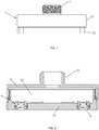
FIG. 1 illustrates a front view of a water outlet device according to an embodiment. -
FIG. 2 illustrates a cross-sectional view of the water outlet device according to the embodiment. -
FIG. 3 illustrates an exploded perspective view of the water outlet device according to the embodiment. -
FIG. 4 illustrates an exploded perspective view of a water outlet assembly of the embodiment. -
FIG. 5 illustrates a perspective view of an ejector of the embodiment. -
FIG. 6 illustrates a first perspective view of a water outlet portion of the embodiment. -
FIG. 7 illustrates a second perspective view of the water outlet portion of the embodiment. -
FIG. 8 illustrates a cross-sectional view of the water outlet assembly of the embodiment. -
FIG. 9 illustrates a first water discharging view of the water outlet assembly of the embodiment. -
FIG. 10 illustrates a second water discharging view of the water outlet assembly of the embodiment. -
FIG. 11 illustrates a third water discharging view of the water outlet assembly of the embodiment. -
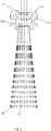
FIG. 12 illustrates a top-down view of the water outlet device of the embodiment. - Reference numbers:
housing portion 1,water outlet assembly 2,upper housing 11,lower housing 12,connector 111,middle cavity 13,ejector 21,jet hole 211,rib 212, upperperipheral wall 213,convex ring 214,middle plate 215,water outlet portion 22, shieldingportion 221,water outlet hole 222, taperedstructure 223, V-shapedsection 224,curved section 225,arc section 226, central area 224', remaining area 225', lowerperipheral wall 227,straight water 31, and half-encompassingwater curtain 32. - Referring to
FIGS. 1-12 , a water outlet device comprises ahousing portion 1 and awater outlet assembly 2. Thehousing portion 1 comprises anupper housing 11 and alower housing 12. Theupper housing 11 is disposed with aconnector 111. Thelower housing 12 is secured to theupper housing 11, and amiddle cavity 13 in communication with the connector is defined between theupper housing 11 and thelower housing 12. The water outlet assembly is secured to thelower housing 12 and is in communication with themiddle cavity 13. Thewater outlet assembly 2 comprises anejector 21 and awater outlet portion 22 disposed along a water flow direction. - The
ejector 21 comprises ajet hole 211. A cross-section of the jet hole defines a non-circular shape. In particular, by way of example, the cross-section of thejet hole 211 defines a plum blossom shape, and a cross-section of the plum blossom shape comprises a plurality of concave areas extending outward (i.e. a corner area). By way of example, figures illustrate six concave areas extending outward, but which are not limited to thereto. As needed, which can illustrate four, five, etc. In a specific structure, theejector 21 comprises a through hole, and an inner wall of the through hole is convex to define one ormore ribs 212. The through hole defines the jet hole due to the one ormore ribs 212, and the jet hole defines a plum blossom shape structure. Thewater outlet portion 22 comprises a shieldingportion 221 and awater outlet hole 222 penetrating through the shieldingportion 221. An opening of thewater outlet hole 222 is enlarged along the water flow direction. Water ejected from thejet hole 211 is divided into an impact portion and a straight portion, and the impact portion impacts the shieldingportion 221 and flows out along an edge (not a peripheral edge) of thewater outlet hole 222 to define a water curtain. The straight portion directly flushes through thewater outlet hole 222 to be ejected to define straight water. Thus, the water flowing from thewater outlet hole 222 comprises thestraight water 31 and the half-encompassingwater curtain 32 that half encompasses thestraight water 31. - In this embodiment: the opening of the
water outlet hole 222 defines a taperedstructure 223 with a large lower end and a small upper end. In a specific structure, thewater outlet hole 222 comprises an upper section and a lower section disposed along the water flow direction. An upper end port of thewater outlet hole 222 extends downward to define the upper section, a lower peripheral edge of the upper section expands and extends downward and outward to define the lower section, and the lower section defines the taperedstructure 223. A peripheral edge of the upper end port of thewater outlet hole 222 comprises a V-shapedsection 224, twocurved sections 225 axially symmetrically disposed on two sides of the V-shaped section, and acircular arc section 226. One ends of the twocurved sections 225 are respectively connected to the two ends of the V-shapedsection 224, and the twocurved sections 225 and the V-shapedsection 224 cooperate to define a substantially W-shaped structure. Two ends of thecircular arc section 226 are respectively connected to the other ends of the twocurved sections 225. An opening of thecircular arc section 226 is disposed opposite to a top angle of the V-shapedsection 224. The curved sections are substantially circular arc-shaped sections, and central angles of the substantially circular arc-shapedsections 225 are greater than 180 degrees. Wherein, a portion encompassed by the V-shapedsection 224 defines a central area 224', a remaining portion in thewater outlet hole 222 except for the central area 224' defines a remaining area 225', and the remaining area 225' half encompasses the central area 224'. Or a portion encompassed by thecurved sections 225 defines the remaining area 225', a remaining portion in thewater outlet hole 222 except for the remaining area 225' defines the central area 224', and the remaining area 225' half encompasses the central area 224'. The straight portion corresponds to the central area 224'. The impact portion impacts the shieldingportion 221 and flows out partially, totally, or breakably along the twocurved sections 225 and/or partially, totally, or breakably along thecircular arc section 226 to define the half-encompassing water curtain having a shape similar to a fan. The half-encompassingwater curtain 32 half encompasses thestraight water 31. The half-encompassingwater curtain 32 is defined by awater curtain 32 due to the above-mentioned structure. When the half-encompassingwater curtain 32 being not closed or being broken in the middle flows through the taperedstructure 223, the water is finally ejected along an outer wall of the water outlet hole to define a fan-shaped water spray expanding outward due to the principle of the Coanda effect. The fan-shaped water spray expands outward. Therefore, when the water spray expands for a certain distance, a fan shape is broken to define particle water spray. A plurality of connecting lines are connected together to define the peripheral edge of the upper end port of the water outlet hole, and connection points of each of the connecting lines are smoothly disposed. - In this embodiment, the
ejector 21 comprises thejet hole 211, and thewater outlet portion 22 comprises a plurality of water outlet holes 222. Figures illustrate three water outlet holes 222, but which are not limited thereto. As needed, which can illustrate four, five, six, etc. Thejet hole 211 corresponds to the plurality of water outlet holes. The plurality of water outlet holes 222 are disposed in an annular array, and an axis of the annular array coincides with an axis of the jet hole. The top angles of the V-shaped sections 224 (i.e. middle top portions of the substantially W-shaped structures) of the plurality of water outlet holes 222 face the axis of the annular array. The plurality of water outlet holes 222 comprise the central areas 224' overlapped by a top-down projection of thejet hole 211 and the remaining areas 225' disposed out of the top-down projection. The top-down projection of thejet hole 211 comprises an overlapped portion disposed on the plurality of water outlet holes 222 and a non-overlapped portion disposed on the shielding portion and outer sides of the plurality of water outlet holes. In this embodiment, the overlapped portion is disposed on the central areas, and the non-overlapped portion defines a middle portion of the shieldingportion 221, so that impacting water just flows downward along an edge of the remaining area. - In this embodiment, the shielding
portion 221 extends upward to define a lowerperipheral wall 227. Theejector 21 comprises an upperperipheral wall 213, and an upper portion of the upper peripheral wall extends outward to define aconvex ring 214. Amiddle plate 215 is secured in the upper peripheral wall, and the middle plate comprises thejet hole 211. The upper peripheral wall cooperates with and is disposed in the lower peripheral wall, and the convex ring abuts an end surface of the lower peripheral wall. Thelower housing 12 comprises a through installation hole, and the lowerperipheral wall 227 is secured in the through installation hole. An outer diameter of the middle plate is smaller than a diameter of the shielding portion. - In this water outlet device, the water flows into the
middle cavity 13 through theupper housing 11 and is diverted to each of thewater outlet assemblies 2. Theejector 21 divides and adjusts the water into a high-speed water flow defining a plum blossom shape. Part of the high-speed water flow (the impact portion) impacts the shieldingportion 221 and decelerates and then flows out along an arc-shaped outer wall of thewater outlet hole 222 to define a fan-shaped water curtain (the half-encompassing water curtain 32). The other part of the high-speed water flow (the straight portion) directly passes through the central area of the water outlet hole to define a water spray with stronger impact force (the straight water 31), and the water curtain disposed in an outer circle surrounds the straight water disposed in an inner circle. A single water outlet hole discharges a unique water spray with both a water curtain and straight water. The water spray has a beautiful appearance and good washing effect, and the water curtain disposed in the outer circle can block water splashing due to the straight water. Moreover, a shape of the water outlet hole is special, and an appearance is highly recognizable. - The aforementioned embodiments are merely some embodiments of the present disclosure, and the scope of the disclosure is not limited thereto. Thus, it is intended that the present disclosure cover any modifications and variations of the presently presented embodiments provided they are made without departing from the appended claims and the specification of the present disclosure.
Claims (15)
- A water outlet assembly (2), characterized in that the water outlet assembly (2)comprises an ejector (21) and a water outlet portion (22) disposed along a water flow direction, the ejector (21) comprises a jet hole (211), the water outlet portion (22) comprises a shielding portion (221) and a water outlet hole (222) penetrating the shielding portion (221), an opening of the water outlet hole (222) is enlarged along the water flow direction, water ejected from the jet hole (211) is divided into an impact portion and a straight portion, the impact portion impacts the shielding portion (221) and flows out along an edge of the water outlet hole (222) to define a water curtain (32), and the straight portion directly flushes through the water outlet hole (222) to be ejected to define straight water (31).
- The water outlet assembly (2) according to claim 1, characterized in that a cross-section of the jet hole (211) comprises a concave area extending outward or a corner area.
- The water outlet assembly (2) according to claim 2, characterized in that the cross-section of the jet hole (211) defines a plum blossom shape.
- The water outlet assembly (2) according to claim 1, characterized in that the ejector (21) comprises a through hole, an inner wall of the through hole is convex to define one or more ribs (212), the through hole defines the jet hole (211) due to the one or more ribs (212), and the jet hole (211) defines a plum blossom shape structure.
- The water outlet assembly (2) according to claim 1, characterized in that the water outlet hole (222) comprises a central area (224') overlapped by a top-down projection of the jet hole (211) and a remaining area (225') disposed out of the top-down projection, the straight portion corresponds to the central area (224'), and the remaining area (225') half encompasses the central area (224') to generate a water curtain (32) to define the water curtain (32) disposed in an outer circle and half encompassing the straight water (31) disposed in an inner circle.
- The water outlet assembly (2) according to claim 5, characterized in that the impact portion impacts the shielding portion (221) and flows downward along an edge of the remaining area of the water outlet hole (222).
- The water outlet assembly (2) according to claim 6, characterized in that the edge of the remaining area (225') comprises an arc section (226), and the impact portion impacts the shielding portion (221) and flows downward at least along the arc section (226).
- The water outlet assembly (2) according to claim 1, characterized in that a periphery of an upper end port of the water outlet hole (222) comprises a V-shaped section (224), two curved sections (225) axially symmetrically disposed on two sides of the V-shaped section (224), and a circular arc section (226), ends of the two curved sections (225) are connected to two ends of the V-shaped section (224), the two curved sections (225) and the V-shaped section (224) cooperate to define a substantially W-shaped structure, two ends of the circular arc section (226) are respectively connected to the other ends of the two curved sections (225), an opening of the circular arc section (226) is disposed opposite to a top angle of the V-shaped section (224), a portion encompassed by the V-shaped section (224) defines a central area (224'), the straight portion corresponds to the central area (224'), and the impact portion flows out along the two curved sections (225) or the two curved sections (225) and the circular arc section (226).
- The water outlet assembly (2) according to claim 1, characterized in that the water outlet portion (22) comprises a plurality of water outlet holes (222), the jet hole (211) corresponds to the plurality of water outlet holes (222), the plurality of water outlet holes (222) are disposed in an annular array, and an axis of the annular array coincides with an axis of the jet hole (211).
- The water outlet assembly (2) according to claim 9, characterized in that upper end ports of the plurality of water outlet holes (222) comprise substantially W-shaped structures, and middle top portions of the W-shaped structures face the axis of the annular array.
- The water outlet assembly (2) according to claim 1, characterized in that a periphery of the shielding portion (221) extends upward to define a lower peripheral wall (227), and the ejector (21) is disposed in an upper port of the lower peripheral wall (227).
- The water outlet assembly (2) according to claim 11, characterized in that the ejector (21) comprises an upper peripheral wall (213), an upper portion of the upper peripheral wall (213) extends outward to define a convex ring (214), a middle plate (215) is secured in the upper peripheral wall (213), the middle plate (215) comprises the jet hole (211), the upper peripheral wall (213) cooperates with and is disposed in the lower peripheral wall (227), and the convex ring (214) abuts an end surface of the lower peripheral wall (227).
- The water outlet assembly (2) according to claim 12, characterized in that an outer diameter of the middle plate (215) is smaller than a diameter of the shielding portion (221).
- A water outlet assembly (2), characterized in that the water outlet assembly (2) comprises an ejector (21) and a water outlet portion (22) disposed along a water flow direction, the ejector (21) comprises a jet hole (22), a cross-section of the jet hole (211) comprises a concave area extending outward or a corner area, the water outlet portion (22) comprises a shielding portion (221) and a water outlet hole (222) penetrating the shielding portion (221), the water outlet hole (222) comprises a central area (224') overlapped by a top-down projection of the jet hole (211) and a remaining area (225') disposed out of the top-down projection, the top-down projection of the jet hole (211) comprises an overlapped portion disposed on the water outlet hole (222) and a non-overlapped portion disposed on the shielding portion (221) and an outer side of the water outlet hole (222), and the concave area extending outward or the corner area of the jet hole (211) corresponds to the central area (224') of the water outlet hole (222).
- A water outlet device, characterized in that the water outlet device comprises a housing portion (1) and the water outlet assembly (2) according to any one of claims 1-14, the housing portion (1) comprises an upper housing (11) and a lower housing (12), the upper housing (11) is disposed with a connector (111), the lower housing (12) is secured to the upper housing (11), a middle cavity (13) in communication with the connector (111) is defined between the upper housing (11) and the lower housing (12), and the water outlet assembly (2) is secured to the lower housing (12).
Applications Claiming Priority (1)
| Application Number | Priority Date | Filing Date | Title |
|---|---|---|---|
| CN202010046969.8A CN113134429B (en) | 2020-01-16 | 2020-01-16 | Water outlet assembly, water outlet device and kitchen faucet |
Publications (1)
| Publication Number | Publication Date |
|---|---|
| EP3851199A1 true EP3851199A1 (en) | 2021-07-21 |
Family
ID=74553562
Family Applications (1)
| Application Number | Title | Priority Date | Filing Date |
|---|---|---|---|
| EP21152093.7A Withdrawn EP3851199A1 (en) | 2020-01-16 | 2021-01-18 | Water outlet assembly and water outlet device |
Country Status (3)
| Country | Link |
|---|---|
| US (1) | US20210222410A1 (en) |
| EP (1) | EP3851199A1 (en) |
| CN (1) | CN113134429B (en) |
Families Citing this family (2)
| Publication number | Priority date | Publication date | Assignee | Title |
|---|---|---|---|---|
| CN216779135U (en) | 2022-01-12 | 2022-06-21 | 沛乐迪(厦门)卫浴有限公司 | Produce play water component of microbubble |
| CN218188979U (en) * | 2022-09-27 | 2023-01-03 | 沛乐迪(厦门)卫浴有限公司 | Micro bubble generating container and water outlet device |
Citations (4)
| Publication number | Priority date | Publication date | Assignee | Title |
|---|---|---|---|---|
| WO2013141719A1 (en) * | 2012-03-23 | 2013-09-26 | Methven Limited | Shower head |
| EP2684610A1 (en) * | 2012-07-13 | 2014-01-15 | Hansgrohe SE | Shower head |
| CN203635373U (en) * | 2013-03-11 | 2014-06-11 | 纽珀有限公司 | Atomizing nozzle for sanitary water outlet piece and sanitary tap with water outlet piece |
| CN209406614U (en) * | 2018-10-15 | 2019-09-20 | 厦门松霖科技股份有限公司 | Outlet component |
Family Cites Families (11)
| Publication number | Priority date | Publication date | Assignee | Title |
|---|---|---|---|---|
| DE19522284B4 (en) * | 1995-06-20 | 2007-05-10 | Robert Bosch Gmbh | Fuel injector |
| DE10202539A1 (en) * | 2002-01-24 | 2003-08-21 | Heinz Kern | Sprinkler nozzle for watering systems has associated baffle plate with one or more openings opening into open ring groove in outside of plate to supply area beneath nozzle |
| AU2002950802A0 (en) * | 2002-08-15 | 2002-09-12 | Skala, Peter | Fluidic vortex amplifier |
| US8313045B2 (en) * | 2007-09-20 | 2012-11-20 | Netafim, Ltd. | Liquid atomizer for agricultural applications |
| KR101036156B1 (en) * | 2009-07-01 | 2011-05-23 | 이장우 | Watering plate |
| DE202013002283U1 (en) * | 2013-03-11 | 2014-06-12 | Neoperl Gmbh | Sprayer nozzle for a sanitary water spout and sanitary outlet fitting with a water outlet |
| CN203750724U (en) * | 2014-03-04 | 2014-08-06 | 厦门松霖科技有限公司 | Shower capable of discharging sector-shaped water |
| CN204583521U (en) * | 2014-12-31 | 2015-08-26 | 厦门松霖科技有限公司 | A kind of splash water discharging device |
| CN107149991B (en) * | 2016-03-04 | 2019-05-03 | 厦门松霖科技股份有限公司 | A water outlet device and shower for generating slow-speed eddy current rotating water |
| CN207017363U (en) * | 2017-06-15 | 2018-02-16 | 开平市汇金卫浴科技有限公司 | Jet regulator |
| CN212284501U (en) * | 2020-01-16 | 2021-01-05 | 厦门松霖科技股份有限公司 | Go out water assembly and go out water installation and kitchen tap |
-
2020
- 2020-01-16 CN CN202010046969.8A patent/CN113134429B/en active Active
-
2021
- 2021-01-15 US US17/150,315 patent/US20210222410A1/en not_active Abandoned
- 2021-01-18 EP EP21152093.7A patent/EP3851199A1/en not_active Withdrawn
Patent Citations (4)
| Publication number | Priority date | Publication date | Assignee | Title |
|---|---|---|---|---|
| WO2013141719A1 (en) * | 2012-03-23 | 2013-09-26 | Methven Limited | Shower head |
| EP2684610A1 (en) * | 2012-07-13 | 2014-01-15 | Hansgrohe SE | Shower head |
| CN203635373U (en) * | 2013-03-11 | 2014-06-11 | 纽珀有限公司 | Atomizing nozzle for sanitary water outlet piece and sanitary tap with water outlet piece |
| CN209406614U (en) * | 2018-10-15 | 2019-09-20 | 厦门松霖科技股份有限公司 | Outlet component |
Also Published As
| Publication number | Publication date |
|---|---|
| CN113134429B (en) | 2025-02-18 |
| CN113134429A (en) | 2021-07-20 |
| US20210222410A1 (en) | 2021-07-22 |
Similar Documents
| Publication | Publication Date | Title |
|---|---|---|
| US10086388B2 (en) | Rain-can style showerhead assembly incorporating eddy filter for flow conditioning in fluidic circuits | |
| US20160339457A1 (en) | Water outlet valve core of a wall mounted shower head and water output device using the same | |
| US20210222410A1 (en) | Water outlet assembly, water outlet device, and kitchen faucet | |
| KR102156450B1 (en) | Shower head | |
| JP2017063831A (en) | Micro bubble shower device | |
| US10722907B2 (en) | Splash water outlet mechanism | |
| CN110523548B (en) | Water outlet nozzle and water spraying device with same | |
| CN108823913A (en) | A kind of swirl washing machine external barrel lid and rotary drum washing machine | |
| CN206168604U (en) | Splash water mechanism goes out | |
| CN215088078U (en) | Shower head capable of discharging different water sprays | |
| CN211329879U (en) | Two-function water outlet assembly and shower head with same | |
| EP4205859A1 (en) | Water outlet structure for generating different spray patterns at its water outlet portions and water outlet device using the same | |
| CN106821249B (en) | sprinkler for dishwasher | |
| CN207170047U (en) | One kind, which is vortexed, is pressurized pulsation water flowing out structure and gondola water faucet | |
| CN114178065A (en) | High-pressure water jet gem nozzle | |
| CN212284501U (en) | Go out water assembly and go out water installation and kitchen tap | |
| US10941554B2 (en) | Nozzle assembly | |
| CN217299189U (en) | Spray nozzle | |
| CN216586850U (en) | Spray head | |
| CN214811794U (en) | Water outlet device and shower head | |
| CN212468538U (en) | Nozzle capable of realizing synergistic atomization of bubbles | |
| CN210022550U (en) | A water outlet mechanism and a shower including the water outlet mechanism | |
| US20250319483A1 (en) | Water outlet structure configured to form spiral granular water and water outlet device | |
| CN224161160U (en) | A water outlet and aerator | |
| CN223660954U (en) | Water outlet device and faucet using same |
Legal Events
| Date | Code | Title | Description |
|---|---|---|---|
| PUAI | Public reference made under article 153(3) epc to a published international application that has entered the european phase |
Free format text: ORIGINAL CODE: 0009012 |
|
| STAA | Information on the status of an ep patent application or granted ep patent |
Free format text: STATUS: THE APPLICATION HAS BEEN PUBLISHED |
|
| AK | Designated contracting states |
Kind code of ref document: A1 Designated state(s): AL AT BE BG CH CY CZ DE DK EE ES FI FR GB GR HR HU IE IS IT LI LT LU LV MC MK MT NL NO PL PT RO RS SE SI SK SM TR |
|
| STAA | Information on the status of an ep patent application or granted ep patent |
Free format text: STATUS: REQUEST FOR EXAMINATION WAS MADE |
|
| 17P | Request for examination filed |
Effective date: 20220121 |
|
| RBV | Designated contracting states (corrected) |
Designated state(s): AL AT BE BG CH CY CZ DE DK EE ES FI FR GB GR HR HU IE IS IT LI LT LU LV MC MK MT NL NO PL PT RO RS SE SI SK SM TR |
|
| STAA | Information on the status of an ep patent application or granted ep patent |
Free format text: STATUS: THE APPLICATION HAS BEEN WITHDRAWN |
|
| 18W | Application withdrawn |
Effective date: 20230119 |