EP3851151A1 - Introducer sheath having a multi-layer hub - Google Patents
Introducer sheath having a multi-layer hub Download PDFInfo
- Publication number
- EP3851151A1 EP3851151A1 EP21161905.1A EP21161905A EP3851151A1 EP 3851151 A1 EP3851151 A1 EP 3851151A1 EP 21161905 A EP21161905 A EP 21161905A EP 3851151 A1 EP3851151 A1 EP 3851151A1
- Authority
- EP
- European Patent Office
- Prior art keywords
- hub
- hub portion
- notch
- introducer
- elongate sheath
- Prior art date
- Legal status (The legal status is an assumption and is not a legal conclusion. Google has not performed a legal analysis and makes no representation as to the accuracy of the status listed.)
- Granted
Links
Images


Classifications
-
- A—HUMAN NECESSITIES
- A61—MEDICAL OR VETERINARY SCIENCE; HYGIENE
- A61B—DIAGNOSIS; SURGERY; IDENTIFICATION
- A61B17/00—Surgical instruments, devices or methods
- A61B17/34—Trocars; Puncturing needles
- A61B17/3468—Trocars; Puncturing needles for implanting or removing devices, e.g. prostheses, implants, seeds, wires
-
- A—HUMAN NECESSITIES
- A61—MEDICAL OR VETERINARY SCIENCE; HYGIENE
- A61M—DEVICES FOR INTRODUCING MEDIA INTO, OR ONTO, THE BODY; DEVICES FOR TRANSDUCING BODY MEDIA OR FOR TAKING MEDIA FROM THE BODY; DEVICES FOR PRODUCING OR ENDING SLEEP OR STUPOR
- A61M25/00—Catheters; Hollow probes
- A61M25/01—Introducing, guiding, advancing, emplacing or holding catheters
- A61M25/06—Body-piercing guide needles or the like
- A61M25/0662—Guide tubes
- A61M25/0668—Guide tubes splittable, tear apart
-
- A—HUMAN NECESSITIES
- A61—MEDICAL OR VETERINARY SCIENCE; HYGIENE
- A61B—DIAGNOSIS; SURGERY; IDENTIFICATION
- A61B17/00—Surgical instruments, devices or methods
- A61B17/34—Trocars; Puncturing needles
-
- A—HUMAN NECESSITIES
- A61—MEDICAL OR VETERINARY SCIENCE; HYGIENE
- A61B—DIAGNOSIS; SURGERY; IDENTIFICATION
- A61B17/00—Surgical instruments, devices or methods
- A61B17/34—Trocars; Puncturing needles
- A61B17/3417—Details of tips or shafts, e.g. grooves, expandable, bendable; Multiple coaxial sliding cannulas, e.g. for dilating
- A61B17/3421—Cannulas
- A61B17/3423—Access ports, e.g. toroid shape introducers for instruments or hands
-
- A—HUMAN NECESSITIES
- A61—MEDICAL OR VETERINARY SCIENCE; HYGIENE
- A61M—DEVICES FOR INTRODUCING MEDIA INTO, OR ONTO, THE BODY; DEVICES FOR TRANSDUCING BODY MEDIA OR FOR TAKING MEDIA FROM THE BODY; DEVICES FOR PRODUCING OR ENDING SLEEP OR STUPOR
- A61M60/00—Blood pumps; Devices for mechanical circulatory actuation; Balloon pumps for circulatory assistance
- A61M60/10—Location thereof with respect to the patient's body
- A61M60/122—Implantable pumps or pumping devices, i.e. the blood being pumped inside the patient's body
- A61M60/126—Implantable pumps or pumping devices, i.e. the blood being pumped inside the patient's body implantable via, into, inside, in line, branching on, or around a blood vessel
- A61M60/13—Implantable pumps or pumping devices, i.e. the blood being pumped inside the patient's body implantable via, into, inside, in line, branching on, or around a blood vessel by means of a catheter allowing explantation, e.g. catheter pumps temporarily introduced via the vascular system
-
- A—HUMAN NECESSITIES
- A61—MEDICAL OR VETERINARY SCIENCE; HYGIENE
- A61M—DEVICES FOR INTRODUCING MEDIA INTO, OR ONTO, THE BODY; DEVICES FOR TRANSDUCING BODY MEDIA OR FOR TAKING MEDIA FROM THE BODY; DEVICES FOR PRODUCING OR ENDING SLEEP OR STUPOR
- A61M60/00—Blood pumps; Devices for mechanical circulatory actuation; Balloon pumps for circulatory assistance
- A61M60/10—Location thereof with respect to the patient's body
- A61M60/122—Implantable pumps or pumping devices, i.e. the blood being pumped inside the patient's body
- A61M60/126—Implantable pumps or pumping devices, i.e. the blood being pumped inside the patient's body implantable via, into, inside, in line, branching on, or around a blood vessel
- A61M60/135—Implantable pumps or pumping devices, i.e. the blood being pumped inside the patient's body implantable via, into, inside, in line, branching on, or around a blood vessel inside a blood vessel, e.g. using grafting
-
- A—HUMAN NECESSITIES
- A61—MEDICAL OR VETERINARY SCIENCE; HYGIENE
- A61M—DEVICES FOR INTRODUCING MEDIA INTO, OR ONTO, THE BODY; DEVICES FOR TRANSDUCING BODY MEDIA OR FOR TAKING MEDIA FROM THE BODY; DEVICES FOR PRODUCING OR ENDING SLEEP OR STUPOR
- A61M60/00—Blood pumps; Devices for mechanical circulatory actuation; Balloon pumps for circulatory assistance
- A61M60/10—Location thereof with respect to the patient's body
- A61M60/122—Implantable pumps or pumping devices, i.e. the blood being pumped inside the patient's body
- A61M60/126—Implantable pumps or pumping devices, i.e. the blood being pumped inside the patient's body implantable via, into, inside, in line, branching on, or around a blood vessel
- A61M60/148—Implantable pumps or pumping devices, i.e. the blood being pumped inside the patient's body implantable via, into, inside, in line, branching on, or around a blood vessel in line with a blood vessel using resection or like techniques, e.g. permanent endovascular heart assist devices
-
- A—HUMAN NECESSITIES
- A61—MEDICAL OR VETERINARY SCIENCE; HYGIENE
- A61M—DEVICES FOR INTRODUCING MEDIA INTO, OR ONTO, THE BODY; DEVICES FOR TRANSDUCING BODY MEDIA OR FOR TAKING MEDIA FROM THE BODY; DEVICES FOR PRODUCING OR ENDING SLEEP OR STUPOR
- A61M60/00—Blood pumps; Devices for mechanical circulatory actuation; Balloon pumps for circulatory assistance
- A61M60/20—Type thereof
- A61M60/205—Non-positive displacement blood pumps
- A61M60/216—Non-positive displacement blood pumps including a rotating member acting on the blood, e.g. impeller
-
- A—HUMAN NECESSITIES
- A61—MEDICAL OR VETERINARY SCIENCE; HYGIENE
- A61M—DEVICES FOR INTRODUCING MEDIA INTO, OR ONTO, THE BODY; DEVICES FOR TRANSDUCING BODY MEDIA OR FOR TAKING MEDIA FROM THE BODY; DEVICES FOR PRODUCING OR ENDING SLEEP OR STUPOR
- A61M60/00—Blood pumps; Devices for mechanical circulatory actuation; Balloon pumps for circulatory assistance
- A61M60/80—Constructional details other than related to driving
- A61M60/855—Constructional details other than related to driving of implantable pumps or pumping devices
- A61M60/865—Devices for guiding or inserting pumps or pumping devices into the patient's body
-
- A—HUMAN NECESSITIES
- A61—MEDICAL OR VETERINARY SCIENCE; HYGIENE
- A61B—DIAGNOSIS; SURGERY; IDENTIFICATION
- A61B17/00—Surgical instruments, devices or methods
- A61B17/34—Trocars; Puncturing needles
- A61B17/3401—Puncturing needles for the peridural or subarachnoid space or the plexus, e.g. for anaesthesia
-
- A—HUMAN NECESSITIES
- A61—MEDICAL OR VETERINARY SCIENCE; HYGIENE
- A61B—DIAGNOSIS; SURGERY; IDENTIFICATION
- A61B17/00—Surgical instruments, devices or methods
- A61B2017/0046—Surgical instruments, devices or methods with a releasable handle; with handle and operating part separable
Definitions
- the first hub portion 112 may form a hemostatic bond with the elongate sheath 102, in particular if the first hub portion 112 and the elongate sheath 102 are both comprised of a same material.
- FIG. 5 shows a perspective view of the first notch 114 in the introducer hub assembly 100 of FIGS. 1 and 2 .
- the first notch 114 is formed in the first hub portion 112 having a minimum thickness 1 32 at the first notch 114.
- the first notch 114 runs the length of the first hub portion 112 from the proximal end portion 115 to the distal end portion 117.
- the first notch 114 is further defined by a first and second ridge 128a and 128b formed in the first hub portion 112.
- the second hub portion 116 partially covers the first hub portion 112 and includes an opening 120 over the first notch 114.
- the second hub portion 116 may have an associated thickness 134.
Landscapes
- Health & Medical Sciences (AREA)
- Heart & Thoracic Surgery (AREA)
- Life Sciences & Earth Sciences (AREA)
- Engineering & Computer Science (AREA)
- Public Health (AREA)
- General Health & Medical Sciences (AREA)
- Biomedical Technology (AREA)
- Veterinary Medicine (AREA)
- Animal Behavior & Ethology (AREA)
- Surgery (AREA)
- Anesthesiology (AREA)
- Hematology (AREA)
- Cardiology (AREA)
- Vascular Medicine (AREA)
- Mechanical Engineering (AREA)
- Pathology (AREA)
- Molecular Biology (AREA)
- Medical Informatics (AREA)
- Nuclear Medicine, Radiotherapy & Molecular Imaging (AREA)
- Biophysics (AREA)
- Pulmonology (AREA)
- Transplantation (AREA)
- Media Introduction/Drainage Providing Device (AREA)
- Infusion, Injection, And Reservoir Apparatuses (AREA)
Abstract
Description
- This application claims priority to
U.S. provisional application number 62/298,171, filed February 22, 2016 - Patients with cardiac ailments are sometimes treated with a percutaneous mechanical circulatory support device, also commonly referred to as a heart pump, configured to assist the natural cardiac pump function or to replace natural cardiac pump function by a continuous pumping operation. These heart pump assemblies can be introduced surgically or percutaneously during a cardiac procedure through the vascular system, such as through blood vessels. In one common approach, pump assemblies are inserted via a catheterization procedure through the femoral artery using an introducer sheath.
- The introducer sheath can provide a reliable access point for the introduction of heart pump assemblies as well as a wide range of diagnostic and therapeutic interventional catheter-based devices. The introducer sheath can be inserted into an artery or vein, and the pump can be advanced through the introducer sheath into the patient. The introducer sheath can then be separated into two halves along a break wall and peeled away while the pump, catheter, and/or guidewire is left in place. This allows physicians to perform clinical procedures that require separation/removal of the introducer sheath without disturbing the position of a pump, catheter, guidewire, and/or other device that has been introduced into and should remain positioned inside of the body.
- As percutaneous heart pumps have become larger and more sophisticated, the introducer sheaths for introduction of the pumps into the body have also necessarily become larger. The larger introducer sheath and hub assembly require a greater breaking force to split the hub of the introducer sheath (e.g., because the thickness of the break wall is greater). The increased break force can make fracturing the hub difficult and less reliable. Furthermore, the increased break force can lead to abrupt breaks of the hub which may undesirably jostle, dislodge, or damage the pump, and/or may in some cases cause discomfort or injury to the healthcare physician administering treatment.
- Disclosed herein is an introducer sheath having a multi-layer hub for percutaneous insertion of a heart pump. The hub can include two or more hub portions formed of different materials so as to reduce the break force required to split the peel-away introducer. The hub has a first hub portion and a second hub portion partially surrounding the first hub portion. The first hub portion includes one or more notches along which the hub is configured to split. The second hub portion includes wings or tabs positioned on either side of the hub which are used as leverage for applying the break force. The first hub portion may be formed of a soft material having a low ultimate strength, while the second hub portion may be formed of a relatively stiff material having an ultimate strength higher than that of the first hub portion. In such a configuration, the soft first hub portion allows the hub to be easily split along the notches in the first material, while the stiff second hub portion has stiff wings which provide improved leverage during breaking. The stiff wings do not bend or flex excessively when a force is applied, but instead transfer applied loads to the notches, thereby facilitating splitting of the introducer. The stiffer wings also reduce the amount of elastic energy that is stored when force is applied to the wings during splitting of the introducer hub. This reduces the sudden release of elastic energy when the hub is split, thereby reducing the risk of displacing or damaging the pump, or causing discomfort or injury to the patient or physician. Thus, by using two hub portions of differing material properties, the systems, methods, and devices described herein can facilitate splitting of the peel-away introducer sheath. By maintaining a low break force, the multilayer hub enables use of wider bore introducer sheathes which would otherwise be too difficult to split.
- The second hub portion may be over-molded on the first hub portion. The overmolding may form a hemostatic bond between the first hub portion and the second hub portion. To strengthen the bond between the two portions, the first hub portion may also include ridges or grooves over which the second hub portion is molded. This can increase the amount of torque that the second hub portion can transmit to the first hub portion without failure of the bond. Additionally, the second hub portion may include an opening above the one or more notches in the first hub portion. This opening allows the first hub portion to easily split in the region of the notch or notches, thus preserving the low break force of the hub.
- In one aspect, an introducer assembly comprises an elongate sheath and a hub. The elongate sheath is sized for insertion into a blood vessel of a patient and includes a longitudinal axis. The hub is coupled to a proximal portion of the sheath and comprises a first hub portion and a second hub portion. The first hub portion comprises a first notch. The second hub portion partially surrounds the first hub portion and comprises two wings and an opening disposed above the first notch. The first hub portion comprises a first material and the second hub portion comprises a second material, wherein the first material differs from the second material. In some implementations, the first material has a first ultimate strength and the second material has a second ultimate strength. In certain implementations, the second ultimate strength is greater than the first ultimate strength. In some implementations, the first material has a first stiffness and the second material has a second stiffness, the second stiffness being greater than the first stiffness.
- In some implementations, the first notch is oriented parallel to the longitudinal axis of the elongate sheath. In certain implementations, the hub is configured to break at the first notch along the direction of the longitudinal axis of the elongate sheath. In some implementations, the elongate sheath has a longitudinal scoring parallel to the longitudinal axis of the elongate sheath. The elongate sheath may be configured to tear along the longitudinal scoring parallel to the longitudinal axis of the elongate sheath.
- In some implementations, the first hub portion includes ridges. In some implementations, the first hub portion and the elongate sheath form a hemostatic bond. In certain implementations, the wings comprise a wide face and a narrow face and the wide face is normal to the longitudinal axis of the elongate sheath. In some implementations, the narrow face of the wings is normal to the longitudinal axis of the elongate sheath. In some implementations, the first hub portion further includes a second notch. In some implementations, the first hub portions include a first ridge and a second ridge which define edges of the first notch.
- In some implementations, the first material has a hardness of about 45 Shore D. In certain implementations, the second material has a hardness of about 68-72 Shore D. In some implementations, the introducer hub has a minimum diameter of about 9 Fr. In other implementations, the introducer hub has a minimum diameter of about 26 Fr. In certain implementations, the first hub portion has a minimum thickness of about 0.1 mm at the first notch. In some implementations, the first hub portion has a maximum thickness of about 0.3 mm at the first notch.
- In some implementations, the thickness of the first hub portion at the first notch is variable along a length of the notch. In some implementations, the thickness of the first hub portion at the first notch is greatest at a proximal end portion of the first notch. In some implementations, the thickness of the first hub portion at the first notch is between about 0.01 inches and 0.012 inches at the proximal end of the first hub. In some implementations, the thickness of the first hub portion at the first notch is between about 0.004 inches and 0.006 inches at a distal end portion of the first hub.
- The foregoing and other objects and advantages will be apparent upon consideration of the following detailed description, taken in conjunction with the accompanying drawings, in which like reference characters refer to like parts throughout, and in which:
-
FIG. 1 shows a top view of an illustrative introducer hub assembly; -
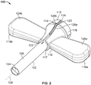
FIG. 2 shows a perspective view of an illustrative introducer hub assembly; -
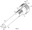
FIG. 3 shows a perspective view of an illustrative first hub portion of an introducer hub assembly; -
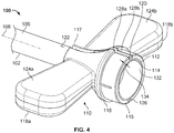
FIG. 4 shows a perspective view of an introducer hub assembly including first and second hub portions; -
FIG. 5 shows a perspective view of a notch of the introducer hub assembly ofFIG. 2 ; -
FIG. 6 shows an end view of an illustrative introducer hub assembly having multiple layers of material; -
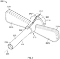
FIG. 7 shows a perspective view of an illustrative introducer hub assembly with wings positioned in a transverse orientation relative to a central longitudinal axis of the introducer hub; and -
FIG. 8 shows an introducer hub assembly inserted into a blood vessel of a patient with a percutaneous pump extending therethrough. - To provide an overall understanding of the systems, methods, and devices described herein, certain illustrative embodiments will be described. Although the embodiments and features described herein are specifically described for use in connection with introducer sheaths for percutaneous insertion of heart pumps, it will be understood that all the components and other features outlined below may be combined with one another in any suitable manner and may be adapted and applied to other types of introducer sheaths, other types of cardiac assist devices, or for the delivery of any suitable catheter, guide wire, surgical tool, or medical device.
- The apparatus described herein includes an introducer and a hub assembly for the introducer (where the introducer can be used, e.g., for percutaneous insertion of a heart pump). The hub can have a first hub portion and a second hub portion partially surrounding the first hub portion. The first hub portion can include a notch along which the hub can be configured to fracture or split. The second hub portion can include wings or tabs positioned on opposite sides of the hub and may be used as leverage for applying the break force. The first hub portion can be formed of a soft material having a low ultimate strength, while the second hub portion can be formed of a relatively stiff material having an ultimate strength that is higher than an ultimate strength of the first hub portion. In such a configuration, the soft first hub portion can allow the hub to be easily fractured or split along the notch in the first material, while the wings of the stiff second hub portion provide improved leverage during breaking. The stiffness of the wings is selected so that the wings do not bend or flex excessively when pressure is applied and instead transfer applied loads to the notches, thereby facilitating splitting of the introducer. The stiffer wings can also reduce the amount of elastic energy that is stored when force is applied to the wings during splitting of the introducer hub. This reduces the sudden release of elastic energy when the hub is split, thereby reducing the risk of displacing or damaging the pump, and/or injuring the patient or physician. Thus, by using two hub portions with differing material properties, the systems, methods, and devices described herein can facilitate splitting of the introducer sheath. By maintaining a low break force, the multilayer hub enables use of introducer sheathes having larger dimensions and/or a larger bore which would otherwise be too difficult to split.
- The hub assembly can be manufactured in various ways and can include different combinations of features. For example, the second hub portion can be over-molded on the first hub portion. The over-molding can form a bond between the first hub portion and the second hub portion that prevents blood from passing through the interface between the first hub portion and the second hub portion. In particular, the bond formed by the over-molding may be a chemical and/or molecular bond. If the first hub portion is formed of a polymer similar to a polymer from which the second hub portion is formed, the polymer chains of the two materials may cross-link at the interface between the first hub portion and second hub portion.
Alternatively, the first and second hubs can be molded separately and then bonded together using any technique known in the art, such as using chemical adhesive. In either instance, the first hub portion may also include ridges or grooves to strengthen the bonding between the first and second hub portions by increasing the surface area for polymer cross-linking and/or to provide a mechanical interlock between the first and second hub portions. This can increase the amount of force that the second hub portion can transmit to the first hub portion without failure of the bond. For another example, the second hub portion may include an opening above the one or more notches in the first hub portion. This opening allows the first hub portion to easily split in the region of the notch, thus preserving the low break force of the hub. By maintaining a low break force, the systems, methods, and devices described herein thus allow introducer hubs to be made larger to accommodate large heart pumps while still breaking apart with application of a reasonable amount of force. -
FIG. 1 shows a top-down view of theintroducer hub assembly 50 including anelongate sheath 2 and ahub 10. Theelongate sheath 2 is sized for insertion into a blood vessel of a patient and has alongitudinal axis 8. Thehub 10 includes afirst hub portion 12 having afirst notch 14, and asecond hub portion 16 having anopening 20 and twowings opening 20 is disposed above thefirst notch 14. Thefirst notch 14 in thefirst hub portion 12 is in some implementations aligned with or at least partially parallel to thelongitudinal axis 8 of theelongate sheath 2. Thesecond hub portion 16 partially covers thefirst hub portion 12. In some implementations, thesecond hub portion 16 is over-molded onto thefirst hub portion 12. Thesecond hub portion 16 includes anopening 20 above thefirst notch 14 which exposes thefirst notch 14. - The
first notch 14 formed in thefirst hub portion 12 provides a break wall at which a crack may be initiated in thehub 10 by applying force to thewings first notch 14 may be formed in a first material having a relatively low ultimate strength break force. Furthermore, thefirst notch 14 may be formed such that a thickness of the first material at the bottom of thefirst notch 14 permits breaking of thehub 10 at thefirst notch 14 at a reasonably low force. Additionally, the shape of thenotch 14 may concentrate stress to facilitate splitting of thehub 10 along thenotch 14. In some implementations, thefirst hub portion 12 has a minimum thickness at thefirst notch 14 of 0.1 mm. In some implementations, thefirst hub portion 12 has a maximum thickness of 0.3 mm at thefirst notch 14. In some implementations thefirst hub portion 112 has a thickness at thefirst notch 14 of 0.075 mm, 0.08 mm, 0.09 mm, 0.1 mm, 0. 15 mm, 0.2 mm, 0.25 mm, 0.3 mm, 0.35 mm, or any other suitable thickness. - The
second hub layer 16 partially surrounding thefirst hub layer 12 allows thewings stiff wings hub 10 at thefirst notch 14. After the hub is broken, thewings introducer hub assembly 50 from the patient and any devices or guidewires extending through the vessel. In some implementations, thesecond hub portion 16 can be over-molded over thefirst hub assembly 12. - During use, the
introducer hub assembly 50 facilitates insertion of a heart pump or other medical object into a blood vessel of a patient. Theintroducer hub assembly 50 is designed as a peel-away introducer. Theelongate sheath 2 is inserted into a blood vessel of the patient and the heart pump is advanced through thehub 10 and through theelongate sheath 2 into the patient. During removal of theintroducer hub assembly 50, thewings hub 10 along thefirst notch 14. A second force may then be applied in a direction opposite the first force to break thehub 10 along a second notch (not shown). Theintroducer hub assembly 50. including thehub 10 andelongate sheath 2, is then peeled away, leaving the heart pump or other medical object undisturbed within the blood vessel of a patient. -
FIG. 2 shows a perspective view of an illustrativeintroducer hub assembly 100. Theintroducer hub assembly 100 includes anelongate sheath 102 and ahub 110. Thehub 110 includes afirst hub portion 112 and asecond hub portion 116. Thefirst hub portion 112 includes afirst notch 114, aproximal end portion 115, and adistal end portion 117. Thesecond hub portion 116 includes anopening 120 above thefirst notch 114 and twowings elongate sheath 102 includes alongitudinal axis 108 and aninternal diameter 104 which is sized to allow a heart pump or medical device to be inserted through theelongate sheath 102 and into a blood vessel of a patient. Theinternal diameter 104 of the elongate sheath may be 2 mm, 3 mm, 4 mm, 5 mm, 6 mm, 7 mm or any other suitable diameter. In some implementations, the inner diameter of the elongate introducer body 105 is compatible with devices that are 9 French (3 mm), 10 French (3.33 mm), 11 French (3.67 mm), 12 French (4 mm), 13 French (4.33 mm), 14 French (4.67mm), 15 French (5 mm), 16 French (5.33 mm), 17 French (5.67 mm), 18 French (6 mm), 19 French (6.33 mm), 20 French (6.67mm), 21 French (7 mm), 22 French (7.33 mm), 24 French (8 mm). 26 French (8.67 mm), or any other suitable diameter. Thefirst hub portion 112 lies closest to anouter surface 106 of theelongate sheath 102. Thefirst hub portion 112 includes afirst notch 114 which is oriented to be parallel to thelongitudinal axis 108 of theelongate sheath 102. Thefirst hub portion 112 also includes afirst ridge 128a and asecond ridge 128b which extend up from surface of theelongate sheath 106, defining thefirst notch 114. Thesecond hub portion 116 partially surrounds thefirst hub portion 112 except at anopening 120 over thefirst notch 114. In some implementations, theopening 102 is also over thefirst ridge 128a andsecond ridge 128b of thefirst hub portion 112 defining thefirst notch 114. Thesecond hub portion 116 includes twowings hub 110. Each of the two wings 1 18a and 118b is constructed to include awide face wings wide face longitudinal axis 108 of theelongate sheath 102. In other implementations, a narrow face 125a and 125b of the wings 1 18a and 118b may be positioned to be normal to thelongitudinal axis 108 of theelongate sheath 102. - After the heart pump or medical device has been inserted into the patient, the
introducer hub assembly 100 can be separated at thehub 110 along the length of thefirst notch 114 and at theelongate sheath 102 along the length of thelongitudinal scoring 122. Thewings introducer assembly 100. This separates thehub 110 at thefirst notch 114 and thelongitudinal scoring 120, fracturing/breaking thehub 110 andelongate sheath 102 in half. In some implementations, thewings elongate sheath 102 to break thehub 110 at thefirst notch 114. In such implementations, thewide face wings longitudinal axis 108 of theelongate sheath 102. In other implementations, the narrow face 125a and 125b of thewings longitudinal axis 108 of theelongate sheath 102 and may be designed such that forcing the twowings first notch 114. Once thehub 110 has been broken at thefirst notch 114, each of thewings hub 110. Theelongate sheath 102 may also include alongitudinal scoring 122 parallel to thelongitudinal axis 108 in line with thefirst notch 114 in thehub 110. Theelongate sheath 102 may be configured to tear along thelongitudinal scoring 122 in order to peel-away when thehub 110 is broken and peeled away by pulling thewings first hub portion 112 may include a second notch (e.g., 126 inFIG. 4 ) opposite thefirst notch 114. In such cases, the second notch is also fractured by pulling thewings elongate sheath 102 may further include a second longitudinal scoring (not shown) at which thehub 110 may be broken and torn. - The
first hub portion 112 and thesecond hub portion 116 may be comprised of material having different material properties. Thefirst hub portion 112 may have different surface properties, durometer, ultimate or tensile strength, modulus of elasticity or other material properties than thesecond hub portion 116. Thesecond hub portion 116 may be more rigid, stiffer, tougher, or harder, relative to thefirst hub portion 112. The different material properties of thefirst hub portion 112 relative to thesecond hub portion 116 allow thehub 110 to be increased in size to accommodate larger pumps and medical devices while still able to be efficiently broken by the medical personnel's hands. In some implementations, the material forming thesecond hub portion 16 has an ultimate strength that is greater than an ultimate strength of the material forming thefirst hub portion 12. In some implementations, the material forming thesecond hub portion 16 has a rigidity that is greater than a rigidity of the material forming thefirst hub portion 12. In certain implementations, the first material forming thefirst hub portion 12 has a hardness of 45 Shore D. In some implementations, the first material may have a hardness of 30 Shore D, 35 Shore D, 40 Shore D, 45 Shore D, 50 Shore D, or any other suitable hardness. In some implementations, the second material forming thesecond hub portion 16 has a hardness of 60 Shore D, 65 Shore D, 68 Shore D, 70 Shore D, 72 Shore D, 75 Shore D, or any other suitable hardness. -
FIG. 3 shows a perspective view of thefirst hub portion 112 of theintroducer hub assembly 100 ofFIG. 2 . Thefirst hub portion 112 is attached to theelongate sheath 102 at a proximal end of theelongate sheath 102 and includes afirst notch 114 defined by afirst ridge 128a and asecond ridge 128b, andridges 130. Thefirst notch 114 may be aligned with alongitudinal scoring 122 on theelongate sheath 102 parallel to thelongitudinal axis 108 of theelongate sheath 102. Thefirst hub portion 112 may define thefirst notch 114 with aminimum thickness 132 of thefirst hub portion 112 at thefirst notch 114. Thefirst notch 114 may be further described by thefirst ridge 128a and thesecond ridge 128b. Theridges 130 may be constructed as ribbed features or grooves oriented in a direction or many directions on thefirst hub portion 112. Theridges 130 allow thefirst hub portion 112 to more securely interface with an over-molded layer, promoting rigidity of the structure during breaking of theintroducer hub assembly 100. Theridges 130 provide a mechanical interlock between thefirst hub portion 112 and the second hub portion (e.g., 116 inFIG. 2 ) to transmit torque applied to the wings (e.g., 1 18a and 118b inFIG. 2 ) to thefirst hub portion 112. The force applied to the wings (e.g., 1 18a and 118b inFIG. 2 ) is thus transmitted to a break wall of thefirst notch 114. Thefirst hub portion 112 may form a hemostatic bond with theelongate sheath 102, in particular if thefirst hub portion 112 and theelongate sheath 102 are both comprised of a same material. -
FIG. 4 shows a perspective view of theintroducer hub assembly 100 according to certain embodiments. Theintroducer hub assembly 100 includes anelongate sheath 102, thefirst hub portion 112 having afirst notch 114 and asecond notch 126, and thesecond hub portion 116 having twowings first hub portion 112 has aproximal end portion 115 and adistal end portion 117. Thefirst hub portion 112 is connected to theelongate sheath 102 at thedistal end portion 117. Thesecond hub portion 116 partially covers thefirst hub portion 112. In some implementations, thesecond hub portion 112 covers thefirst hub portion 116 in near entirety except at anopening 120 above thefirst notch 114. In some implementations, the second hub portion may cover a smaller portion of thefirst hub portion 112. As described above, the first and second hub portions can be formed using various techniques (e.g., over-molding thesecond hub portion 116 onto thefirst hub portion 112 or molding the first andsecond hub portions - The
first notch 114 is oriented parallel to alongitudinal axis 108 of theelongate sheath 102 and is in line with alongitudinal scoring 122 of theelongate sheath 102 such that thehub assembly 100 may function as a peel-away introducer upon breaking of thehub 110 at thefirst notch 114 and tearing of theelongate sheath 102 along thelongitudinal scoring 122. Thehub 110 has asecond notch 126 in thefirst hub portion 112 shown on an opposite side of thehub 110 as thefirst notch 114. Thesecond notch 126 further facilitates breaking of thehub 110 for removal of thehub assembly 100. Thesecond notch 126 may be defined in a similar way as thefirst notch 114 and may also be oriented to be parallel to thelongitudinal axis 108 of theelongate sheath 102. Thelongitudinal sheath 102 may include a second longitudinal scoring (not shown) which is aligned with thesecond notch 126 and is opposite thelongitudinal scoring 122. - During removal of the introducer assembly 100 a force is applied to the
wings first notch 114, there is a compressive force in the hub at thefirst notch 114 and a tension at thesecond notch 126 such that both thefirst notch 114 is broken. Application of a force to the wings in the opposite direction breaks thesecond notch 126. Thefirst notch 114 in thefirst hub portion 112 and theminimum thickness 132 of thefirst hub portion 112 at thefirst notch 114 andsecond notch 126 allows thehub 110 to be easily broken at thefirst notch 114 andsecond notch 126. The first hub portion may comprise a material having a low ultimate strength to further facilitate the breaking of thehub 110 at thefirst notch 114 and thesecond notch 126. Thesecond hub portion 116 may comprise a material having a higher ultimate strength than the material of thefirst hub portion 112. In some implementations, thefirst hub portion 112 and thesecond hub portion 116 may be comprised of polyether block amide (e.g., PEBAX® manufactured by Arkema Group) or similar material. Thesecond hub portion 116 includes thewings hub 110 without flexing, facilitating breaking of the hub. Further, thesecond hub portion 116 may have an increasedthickness 134 where it covers thefirst hub portion 112 in order to provide rigidity to thehub 110. -
FIG. 5 shows a perspective view of thefirst notch 114 in theintroducer hub assembly 100 ofFIGS. 1 and2 . Thefirst notch 114 is formed in thefirst hub portion 112 having a minimum thickness 1 32 at thefirst notch 114. Thefirst notch 114 runs the length of thefirst hub portion 112 from theproximal end portion 115 to thedistal end portion 117. Thefirst notch 114 is further defined by a first andsecond ridge first hub portion 112. Thesecond hub portion 116 partially covers thefirst hub portion 112 and includes anopening 120 over thefirst notch 114. Thesecond hub portion 116 may have an associatedthickness 134. In some implementations thefirst hub portion 112 has aminimum thickness 132 of 0.1 mm at thefirst notch 114. In some implementations, thefirst hub portion 112 has a maximum thickness of 0.3 mm at thefirst notch 114. In certain implementations, thefirst hub portion 112 has athickness 132 at thefirst notch 114 of 0.075 mm, 0.08 mm, 0.09 mm, 0.1 mm, 0.15 mm, 0.2 mm, 0.25 mm, 0.3 mm, 0.35 mm, or any other suitable thickness. - In some implementations, the
first hub portion 112 has avariable thickness 132 at thefirst notch 114 along the length of thefirst notch 114. In certain implementations, thefirst hub portion 112 has agreater thickness 132 at theproximal end portion 115 of thefirst hub portion 112 than at thedistal end portion 117. Thedistal end portion 117 of thenotch 114 nearest the connection between thehub 110 and theelongate sheath 102 can have the maximum stress concentration during fracture and may therefore be the intended initiation point of the break. Thus, a relatively thin break wall of thenotch 114 at thedistal end portion 117 reduces the force required to start the break. - In some implementations, a hemostatic valve (not shown) is included in the
hub 110 at theproximal end portion 115. Theproximal end portion 115 in which the valve is disposed must be strong enough to support the hoop stress induced in thehub 110 from compression of the valve. This is especially important when objects, such as catheters, are inserted through the hub, increasing the hoop stress. In some implementations, thethickness 132 of thenotch 114 at theproximal end portion 115 is greater than the thickness of thenotch 114 at thedistal end portion 117. The increased notch thickness at theproximal end portion 115 reinforces thehub 110 in the area of increased hoop stress. In some implementations, the thickness of thenotch 114 at thedistal end portion 117 is around 0.004" - 0.006". In some implementations, the thickness of thenotch 114 atdistal end portion 117 is 0.003", 0.0035", 0.004", 0.0045", 0.005", 0.0055", 0.006", 0.0065" or any other suitable thickness. In some implementations, the thickness of thenotch 114 at theproximal end portion 115 of thefirst hub portion 112 is around 0.010" - 0.012". In some implementations, the thickness of thenotch 114 at theproximal end portion 115 of thefirst hub portion 112 is 0.0095", 0.010", 0.0105", 0.011", 0.01 15", 0.012", 0.0125" or any other suitable thickness. In some implementations, the change in thickness may occur over a smooth transition. In some implementations, the change in thickness may occur via a series of steps of increased thickness. - The use of the softer material to form the
first hub portion 112 allows the variation in the thickness of thenotch 114 along its length. This is because the thickness of thenotch 114 is constrained on the upper end by the maximum allowable break force and on the lower end by manufacturing tolerances. If thenotch 114 is too thick, it cannot be broken. But if it is too thin, it cannot be easily manufactured by traditional processes (e.g., injection molding). The use of a softer material for thefirst hub portion 112 increases the upper limit for the notch thickness because it enables sufficiently low break force at greater notch thicknesses. This increase in the upper limit of the notch thickness affords a range within which the notch thickness can vary, thereby enabling variation in the notch thickness along the length of the notch. Thus, the use of a different material for thefirst hub portion 112 compared to thesecond hub portion 116 enables varying the thickness of the notch along the length of the notch. -
FIG. 6 shows a perspective view along thelongitudinal axis 108 of theelongate sheath 102 of anintroducer hub assembly 100 according to certain embodiments. Theintroducer hub assembly 100 includes theelongate sheath 102 sized to fit a heart pump or medical device and to be inserted into a blood vessel of a patient. Theelongate sheath 102 is surrounded by thefirst hub portion 112 including afirst notch 114 at which point the thickness of thefirst hub portion 112 may be at aminimum thickness 132. Asecond hub portion 116 surrounds thefirst hub portion 112 and includes anopening 120 over thefirst notch 114. In some implementations, thefirst notch 114 may be further defined by a ridge or extension of the first hub portion 112 (shown as 128a and 128b inFIG. 5 ). In some implementations, a base of thefirst notch 114 may be defined by thefirst hub portion 112 and thesecond hub portion 116 may further define an upper portion of thefirst notch 114. Thesecond hub portion 116 also includes afirst wing 118a and asecond wing 118b. -
FIG. 7 shows a perspective view of an alternative embodiment of theintroducer hub assembly 200 withwings introducer hub assembly 200 includes anelongate sheath 202 having aninner diameter 204 sized to allow the passage of a heart pump into a blood vessel of a patient and alongitudinal axis 208, afirst hub portion 212 having afirst notch 214, and asecond hub portion 216 having anopening 220 over thefirst notch 214 and first andsecond wings - The
first wing 218a and thesecond wing 218b are oriented such thatwide faces wings longitudinal axis 208 of theelongate sheath 202. In this embodiment, theintroducer hub assembly 200 is fractured and separated from the patient using a different technique than for the embodiment ofFIG. 1 . More specifically, to break thehub 210 at thefirst notch 214, the wide faces 224a and 224b of thewings elongate sheath 202. Thehub 210 fractures along thefirst notch 214 and along a second notch (not shown) opposite thefirst notch 214. Additionally, theelongate sheath 202 tears at alongitudinal scoring 222 and at a second longitudinal scoring (not shown) which is opposite thelongitudinal scoring 222. Theintroducer hub assembly 200 is now broken in half and can be removed, leaving the device, catheter or guidewire in place in a blood vessel of a patient. -
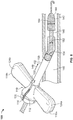
FIG. 8 shows theintroducer hub assembly 100 ofFIGS. 2 ,4 and6 inserted into a blood vessel of apatient 140 with apercutaneous pump 142 extending partially therethrough. Thepercutaneous pump 142 can include various features, such as apump head 144 and acatheter body 146. Thepercutaneous pump 142 may be an intravascular heart pump, a heart pump driven by a flexible shaft and a motor positioned external to the patient's body, a heart pump including an implantable motor, a heart pump having an expandable pump rotor, or any other suitable pump. Theintroducer hub assembly 100 is advanced into theblood vessel 140 through theblood vessel aperture 150 in the direction indicated byarrow 148 and then thepercutaneous pump 142 is inserted through theintroducer hub assembly 100 and into theblood vessel 140. Theblood vessel 140 may be a femoral artery, and theblood vessel aperture 150 may be an arteriotomy. - After the
percutaneous pump 142 has been advanced through theintroducer hub assembly 100 theintroducer hub assembly 100 may be removed and in some implementations replaced by a device appropriate for longer-term use. To remove the introducer hub assembly, a healthcare professional may grasp the first and second wings 1 18a and 118b and apply a force to thewings elongate sheath 102 or a direction radial to theelongate sheath 102 forcing afirst wing 118a toward thesecond wing 118b depending on the orientations of the first andsecond wings elongate sheath 102. In the orientation ofwings wings second wings second hub portion 116 and do not flex when force is applied. The applied force is transmitted from thewings first notch 114 and the second notch 126 (not shown). Theminimum thickness 132 of thefirst hub portion 112 at thefirst notch 114 andsecond notch 126 allows thehub 110 to be broken at thefirst notch 114 andsecond notch 126. In some implementations, the healthcare professional applies a second radial force in an opposite direction in order to break thesecond notch 126. Thelongitudinal scoring 122 on theelongate sheath 102 allows the sheath to separate along thelongitudinal axis 208, and thehub 110 andelongate sheath 102 may be peeled away in two pieces leaving thepercutaneous pump 142 in place in theblood vessel 140. - The foregoing is merely illustrative of the principles of the disclosure, and the apparatuses can be practiced by other than the described embodiments, which are presented for purposes of illustration and not of limitation. It is to be understood that the apparatuses disclosed herein, while shown for use in percutaneous insertion of heart pumps, may be applied to apparatuses in other applications requiring hemostasis.
- Variations and modifications will occur to those of skill in the art after reviewing this disclosure. The disclosed features may be implemented, in any combination and subcombination (including multiple dependent combinations and subcombinations), with one or more other features described herein. The various features described or illustrated above, including any components thereof, may be combined or integrated in other systems. Moreover, certain features may be omitted or not implemented.
- Examples of changes, substitutions, and alterations are ascertainable by one skilled in the art and could be made without departing from the scope of the information disclosed herein. All references cited herein are incorporated by reference in their entirety and made part of this application.
- Preferred embodiments of the invention are described in the following paragraphs 1 to 23:
- 1. An introducer assembly comprising:
- an elongate sheath sized for insertion into a blood vessel of a patient, the sheath having a longitudinal axis;
- a hub coupled to a proximal portion of the sheath, the hub comprising:
- a first hub portion having a first notch;
- a second hub portion partially surrounding the first hub portion, the second hub portion comprising:
- two wings; and
- an opening disposed above the first notch; and
- wherein the first hub portion comprises a first material and the second hub portion comprises a second material, the first material differing from the second material.
- 2. The introducer assembly of para 1, wherein the first material has a first ultimate strength and the second material has a second ultimate strength, the second ultimate strength being greater than the first ultimate strength.
- 3. The introducer assembly of para 1, wherein the first material has a first stiffness and the second material has a second stiffness, the second stiffness being greater than the first stiffness.
- 4. The introducer assembly as in any one of
paras 1, 2 and 3, wherein the first notch is oriented parallel to the longitudinal axis of the elongate sheath. - 5. The introducer assembly of any of paras 1-4, wherein the hub is configured to break at the first notch along a direction of the longitudinal axis of the elongate sheath.
- 6. The introducer hub of any of paras 1-5, wherein the elongate sheath further comprises a longitudinal scoring parallel to the longitudinal axis of the elongate sheath.
- 7. The introducer assembly of any of paras 1-6, wherein the elongate sheath is configured to tear along the longitudinal scoring parallel to the longitudinal axis of the elongate sheath.
- 8 The introducer assembly of any of paras 1-7, wherein the first hub portion includes ridges.
- 9. The introducer assembly of any of paras 1-8, wherein the first hub portion and the elongate sheath form a hemostatic bond.
- 10. The introducer assembly of any of paras 1-9, wherein the wings each comprise a wide face and a narrow face, and the wide face is normal to the longitudinal axis of the elongate sheath.
- 11. The introducer assembly of any of paras 1-10, wherein the wings each comprise a wide face and a narrow face, and the narrow face is normal to the longitudinal axis of the elongate sheath.
- 12. The introducer assembly of any of paras 1-11, wherein the first hub portion comprises a second notch.
- 13. The introducer assembly of any of paras 1-12, wherein the first hub portion includes a first ridge and a second ridge which define edges of the first notch.
- 14. The introducer assembly of any of paras 1-13, wherein the first material has a hardness of about 45 Shore D.
- 15. The introducer assembly of any of paras 1- 14, wherein the second material has a hardness in the range of about 68-72 Shore D.
- 16. The introducer assembly of any of paras 1-15, wherein the hub has a minimum diameter of about 9 Fr.
- 17. The introducer assembly of any of paras 1-16, wherein the hub has a minimum diameter of about 26 Fr.
- 18. The introducer assembly of any of paras 1-17, wherein the first hub portion has a minimum thickness of 0.1 mm at the first notch.
- 19. The introducer assembly of any of paras 1-18, wherein the first hub portion has a maximum thickness of 0.3 mm at the first notch.
- 20. The introducer assembly of any of paras 1-19, wherein the thickness of the first hub portion at the first notch is variable along a length of the notch.
- 21. The introducer assembly of
para 20, wherein the thickness of the first hub portion at the first notch is greatest at a proximal end portion of the first hub portion. - 22. The introducer assembly of para 21, wherein the thickness of the first hub portion at the first notch is between about 0.01 inches and 0.012 inches at the proximal end portion of the first hub portion.
- 23. The introducer assembly of para 21, wherein the thickness of the first hub portion at the first notch is between about 0.004 inches and 0.006 inches at a distal end portion of the first hub portion.
Claims (15)
- An introducer assembly (50, 100, 200) comprising:an elongate sheath (2, 102, 202) sized for insertion into a blood vessel of a patient, the sheath having a longitudinal axis (8, 108, 208);a hub (10, 110, 210) coupled to a proximal portion of the elongate sheath (2, 102, 202), the hub (10, 110, 210) comprising:a first hub portion (12, 112, 212) having a first notch (14, 114, 214);a second hub portion (16, 116, 216) partially surrounding the first hub portion (12, 112, 212), the second hub portion (16, 116, 216) comprising:two wings (18a, 18b, 118a, 118b, 218a, 218b); andan opening (20, 120, 220) disposed above the first notch (14, 114, 214); andwherein the first hub portion (12, 112, 212) comprises a first material and the second hub portion (16, 116, 216) comprises a second material, the first material differing from the second material.
- The introducer assembly (50, 100, 200) of claim 1, wherein the first material has a first ultimate strength and the second material has a second ultimate strength, the second ultimate strength being greater than the first ultimate strength.
- The introducer assembly (50, 100, 200) of claim 1, wherein the first material has a first stiffness and the second material has a second stiffness, the second stiffness being greater than the first stiffness.
- The introducer assembly (50, 100, 200) of any one of claims 1 to 3, wherein the first notch (14, 114, 214) is oriented parallel to the longitudinal axis (8, 108, 208) of the elongate sheath (2, 102, 202).
- The introducer assembly (50, 100, 200) of any one of claims 1 to 4, wherein the hub (10, 110, 210) is configured to break at the first notch (14, 114, 214) along a direction of the longitudinal axis (8, 108, 208) of the elongate sheath (2, 102, 202).
- The introducer assembly (50, 100, 200) of any one of claims 1 to 5, wherein the elongate sheath (2, 102, 202) further comprises a longitudinal scoring (122, 222) parallel to the longitudinal axis (8, 108, 208) of the elongate sheath (2, 102, 202).
- The introducer assembly (50, 100, 200) of claim 6, wherein the elongate sheath (2, 102, 202) is configured to tear along the longitudinal scoring (122, 222) parallel to the longitudinal axis (8, 108, 208) of the elongate sheath (2, 102, 202).
- The introducer assembly (50, 100, 200) of any one of claims 1 to 7, wherein the first hub portion (12, 112, 212) includes ridges (128a, 128b).
- The introducer assembly (50, 100, 200) of any one of claims 1 to 8, wherein the first hub portion (12, 112, 212) and the elongate sheath (2, 102, 202) form a hemostatic bond.
- The introducer assembly (50, 100, 200) of any one of claims 1 to 9, wherein the wings (18a, 18b, 118a, 118b, 218a, 218b) each comprise a wide face (124a, 124b, 224a, 224b) and a narrow face (125a, 125b), and the wide face (124a, 124b, 224a, 224b) is normal to the longitudinal axis (8, 108, 208) of the elongate sheath (2, 102, 202).
- The introducer assembly (50, 100, 200) of any one of claims 1 to 9, wherein the wings (18a, 18b, 118a, 118b, 218a, 218b) each comprise a wide face (124a, 124b, 224a, 224b) and a narrow face (125a, 125b), and the narrow face (125a, 125b) is normal to the longitudinal axis (8, 108, 208) of the elongate sheath (2, 102, 202).
- The introducer assembly (50, 100, 200) of any one of claims 1 to 11, wherein the first hub portion (12, 112, 212) comprises a second notch (126).
- The introducer assembly (50, 100, 200) of any one of claims 1 to 12, wherein the first hub portion (12, 112, 212) includes a first ridge (128a) and a second ridge (128b) which define edges of the first notch (14, 114, 214).
- The introducer assembly (50, 100, 200) of any one of claims 1 to 13, wherein a thickness (132) of the first hub portion (12, 1 12, 212) at the first notch (14, 114, 214) is variable along a length of the first notch (14, 114, 214).
- The introducer assembly (50, 100, 200) of claim 14, wherein the thickness (132) of the first hub portion (12, 112, 212) at the first notch (14, 114, 214) is greatest at a proximal end portion (115) of the first hub portion (12, 112, 212).
Priority Applications (1)
| Application Number | Priority Date | Filing Date | Title |
|---|---|---|---|
| EP25164077.7A EP4545132A3 (en) | 2016-02-22 | 2017-02-22 | Introducer sheath having a multi-layer hub |
Applications Claiming Priority (3)
| Application Number | Priority Date | Filing Date | Title |
|---|---|---|---|
| US201662298171P | 2016-02-22 | 2016-02-22 | |
| PCT/US2017/018791 WO2017147103A1 (en) | 2016-02-22 | 2017-02-22 | Introducer sheath having a multi-layer hub |
| EP17757090.0A EP3419711B1 (en) | 2016-02-22 | 2017-02-22 | Introducer sheath having a multi-layer hub |
Related Parent Applications (1)
| Application Number | Title | Priority Date | Filing Date |
|---|---|---|---|
| EP17757090.0A Division EP3419711B1 (en) | 2016-02-22 | 2017-02-22 | Introducer sheath having a multi-layer hub |
Related Child Applications (1)
| Application Number | Title | Priority Date | Filing Date |
|---|---|---|---|
| EP25164077.7A Division EP4545132A3 (en) | 2016-02-22 | 2017-02-22 | Introducer sheath having a multi-layer hub |
Publications (2)
| Publication Number | Publication Date |
|---|---|
| EP3851151A1 true EP3851151A1 (en) | 2021-07-21 |
| EP3851151B1 EP3851151B1 (en) | 2025-03-26 |
Family
ID=59630824
Family Applications (3)
| Application Number | Title | Priority Date | Filing Date |
|---|---|---|---|
| EP25164077.7A Pending EP4545132A3 (en) | 2016-02-22 | 2017-02-22 | Introducer sheath having a multi-layer hub |
| EP21161905.1A Active EP3851151B1 (en) | 2016-02-22 | 2017-02-22 | Introducer sheath having a multi-layer hub |
| EP17757090.0A Active EP3419711B1 (en) | 2016-02-22 | 2017-02-22 | Introducer sheath having a multi-layer hub |
Family Applications Before (1)
| Application Number | Title | Priority Date | Filing Date |
|---|---|---|---|
| EP25164077.7A Pending EP4545132A3 (en) | 2016-02-22 | 2017-02-22 | Introducer sheath having a multi-layer hub |
Family Applications After (1)
| Application Number | Title | Priority Date | Filing Date |
|---|---|---|---|
| EP17757090.0A Active EP3419711B1 (en) | 2016-02-22 | 2017-02-22 | Introducer sheath having a multi-layer hub |
Country Status (9)
| Country | Link |
|---|---|
| US (4) | US10709476B2 (en) |
| EP (3) | EP4545132A3 (en) |
| JP (3) | JP7085488B2 (en) |
| CN (1) | CN210583327U (en) |
| AU (3) | AU2017223417B2 (en) |
| DK (2) | DK3419711T3 (en) |
| ES (2) | ES2873358T3 (en) |
| IL (3) | IL299692B2 (en) |
| WO (1) | WO2017147103A1 (en) |
Cited By (5)
| Publication number | Priority date | Publication date | Assignee | Title |
|---|---|---|---|---|
| US12403296B2 (en) | 2018-05-30 | 2025-09-02 | Kardion Gmbh | Apparatus for anchoring a ventricular assist system in a blood vessel, operating method, production method for producing an apparatus and ventricular assist system |
| US12478775B2 (en) | 2018-07-09 | 2025-11-25 | Kardion Gmbh | Cardiac assist system, and method for monitoring the integrity of a retaining structure of a cardiac assist system |
| US12576263B2 (en) | 2018-05-30 | 2026-03-17 | Kardion Gmbh | Device for attaching a heart support system to an insertion device, and method for producing same |
| US12589237B2 (en) | 2020-11-20 | 2026-03-31 | Kardion Gmbh | Mechanical circulatory support system with guidewire aid |
| US12599749B2 (en) | 2018-05-30 | 2026-04-14 | Kardion Gmbh | Controllable insertion sleeve |
Families Citing this family (29)
| Publication number | Priority date | Publication date | Assignee | Title |
|---|---|---|---|---|
| EP4487798A3 (en) | 2015-01-07 | 2025-02-26 | Abiomed Europe GmbH | Introducer sheath |
| WO2017147103A1 (en) * | 2016-02-22 | 2017-08-31 | Abiomed, Inc. | Introducer sheath having a multi-layer hub |
| IL300057B2 (en) | 2016-12-08 | 2024-04-01 | Abiomed Inc | Overmold technique for peel-away introducer design |
| EP4732889A2 (en) | 2017-06-07 | 2026-04-29 | Supira Medical, Inc. | Intravascular fluid movement devices, systems, and methods of use |
| CN116269685A (en) * | 2017-09-14 | 2023-06-23 | 阿比奥梅德公司 | Integrated expandable access for medical device introducer |
| SG11202003104SA (en) * | 2017-11-06 | 2020-05-28 | Abiomed Inc | Peel away hemostasis valve |
| US11511103B2 (en) | 2017-11-13 | 2022-11-29 | Shifamed Holdings, Llc | Intravascular fluid movement devices, systems, and methods of use |
| JP7410034B2 (en) | 2018-02-01 | 2024-01-09 | シファメド・ホールディングス・エルエルシー | Intravascular blood pump and methods of use and manufacture |
| AU2019269627B2 (en) | 2018-05-16 | 2025-02-06 | Abiomed, Inc. | Peel-away sheath assembly |
| DE102018208892A1 (en) | 2018-06-06 | 2019-12-12 | Kardion Gmbh | A sensor head device for a minimally invasive cardiac assist system and method of manufacturing a sensor head device for a cardiac assist system |
| DE102018208931A1 (en) | 2018-06-06 | 2019-12-12 | Kardion Gmbh | Apparatus for determining cardiac output for a cardiac assist system, cardiac assistive system and method for determining cardiac output |
| DE102018208870A1 (en) | 2018-06-06 | 2019-12-12 | Kardion Gmbh | A method of determining a fluid volume flow through an implanted vascular support system |
| WO2020028537A1 (en) | 2018-07-31 | 2020-02-06 | Shifamed Holdings, Llc | Intravascaular blood pumps and methods of use |
| DE102018213350A1 (en) | 2018-08-08 | 2020-02-13 | Kardion Gmbh | Device and method for monitoring a patient's health |
| WO2020073047A1 (en) | 2018-10-05 | 2020-04-09 | Shifamed Holdings, Llc | Intravascular blood pumps and methods of use |
| EP3866876B1 (en) | 2018-10-18 | 2022-11-30 | Abiomed, Inc. | Systems for minimizing leaks during insertion of pumps |
| EP3938028B1 (en) * | 2019-03-14 | 2024-06-12 | St. Jude Medical, Cardiology Division, Inc. | Splittable sheath |
| WO2021011473A1 (en) | 2019-07-12 | 2021-01-21 | Shifamed Holdings, Llc | Intravascular blood pumps and methods of manufacture and use |
| US11654275B2 (en) | 2019-07-22 | 2023-05-23 | Shifamed Holdings, Llc | Intravascular blood pumps with struts and methods of use and manufacture |
| EP4010046A4 (en) | 2019-08-07 | 2023-08-30 | Calomeni, Michael | CATHETER BLOOD PUMPS AND COLLAPSIBLE PUMP HOUSINGS |
| EP4034221B1 (en) | 2019-09-25 | 2024-11-13 | Shifamed Holdings, LLC | Catheter blood pumps and collapsible pump housings |
| EP4034192B1 (en) | 2019-09-25 | 2025-12-24 | Supira Medical, Inc. | Intravascular blood pump systems and methods of use and control thereof |
| WO2021062260A1 (en) | 2019-09-25 | 2021-04-01 | Shifamed Holdings, Llc | Catheter blood pumps and collapsible blood conduits |
| JP2022552944A (en) * | 2019-09-30 | 2022-12-21 | アビオメド インコーポレイテッド | collapsible catheter |
| EP4072650A4 (en) | 2019-12-11 | 2024-01-10 | Shifamed Holdings, LLC | DESCENDING AORTA AND VEINA CAVA BLOOD PUMPS |
| US12599758B2 (en) | 2019-12-19 | 2026-04-14 | Shifamed Holdings, Llc | Intravascular blood pumps, motors, and fluid control |
| US11963671B2 (en) * | 2020-07-09 | 2024-04-23 | Tc1 Llc | Catheter system for introducing expandable medical device and methods of using same |
| USD1028226S1 (en) * | 2021-04-15 | 2024-05-21 | Koninklijke Philips N.V. | Catheter interface |
| US12502524B2 (en) | 2021-12-03 | 2025-12-23 | Kardion Gmbh | Cardiac pump with optical fiber for laser doppler |
Citations (2)
| Publication number | Priority date | Publication date | Assignee | Title |
|---|---|---|---|---|
| US20090192463A1 (en) * | 2008-01-29 | 2009-07-30 | Medical Components, Inc | Introducer Sheath Assembly with Hub and Method of Joining a Hub to a Sheath Tube |
| US20140025003A1 (en) * | 2011-07-22 | 2014-01-23 | Greatbatch Ltd. | Introducer Handle Notch Design/Concept |
Family Cites Families (53)
| Publication number | Priority date | Publication date | Assignee | Title |
|---|---|---|---|---|
| US4699611A (en) | 1985-04-19 | 1987-10-13 | C. R. Bard, Inc. | Biliary stent introducer |
| JPH02102667A (en) | 1988-10-12 | 1990-04-16 | Nippon Zeon Co Ltd | Easily split plastic indwelling needle |
| US5234425A (en) | 1989-03-03 | 1993-08-10 | Thomas J. Fogarty | Variable diameter sheath method and apparatus for use in body passages |
| JPH03292963A (en) * | 1990-04-10 | 1991-12-24 | Nissho Corp | Easy splittable cannula |
| US5139486A (en) | 1991-01-02 | 1992-08-18 | Gerald Moss | Dilator/introducer for percutaneous gastrostomy |
| US5167634A (en) | 1991-08-22 | 1992-12-01 | Datascope Investment Corp. | Peelable sheath with hub connector |
| WO1993006878A1 (en) | 1991-10-11 | 1993-04-15 | Boston Scientific Corporation | Catheter introducer sheath assembly |
| US5395349A (en) | 1991-12-13 | 1995-03-07 | Endovascular Technologies, Inc. | Dual valve reinforced sheath and method |
| US5935122A (en) | 1991-12-13 | 1999-08-10 | Endovascular Technologies, Inc. | Dual valve, flexible expandable sheath and method |
| US5304142A (en) | 1992-08-04 | 1994-04-19 | Medamicus, Inc. | Dilator - Introducer locking hub and sheath valve apparatus |
| US5320611A (en) | 1993-02-04 | 1994-06-14 | Peter M. Bonutti | Expandable cannula having longitudinal wire and method of use |
| US6338730B1 (en) | 1993-02-04 | 2002-01-15 | Peter M. Bonutti | Method of using expandable cannula |
| US5492530A (en) | 1994-02-07 | 1996-02-20 | Cathco, Inc. | Method for accessing the coronary arteries from the radial or brachial artery in the arm |
| US5395341A (en) | 1994-03-21 | 1995-03-07 | Cordis Corporation | One piece vessel dilator/catheter sheath introducer |
| US5407430A (en) | 1994-03-21 | 1995-04-18 | Peters; Michael J. | Intravenous catheter |
| US5488960A (en) | 1994-04-11 | 1996-02-06 | Abbott Laboratories | Coronary sinus catheter introducer system |
| US5536255A (en) | 1994-10-03 | 1996-07-16 | Moss; Gerald | Dilator/introducer apparatus for percutaneous gastrostomy |
| US5489273A (en) * | 1994-10-07 | 1996-02-06 | Tfx Medical, Incorporated | Introducer device and methods of use thereof |
| US5971993A (en) | 1996-11-07 | 1999-10-26 | Myocardial Stents, Inc. | System for delivery of a trans myocardial device to a heart wall |
| US5911702A (en) | 1997-11-06 | 1999-06-15 | Heartport, Inc. | Methods and devices for cannulating a patient's blood vessel |
| US6692462B2 (en) | 1999-05-19 | 2004-02-17 | Mackenzie Andrew J. | System and method for establishing vascular access |
| US6607547B1 (en) | 1999-08-25 | 2003-08-19 | Origin Medsystems, Inc. | Longitudinal dilator and method |
| US20060287574A1 (en) | 1999-08-25 | 2006-12-21 | Chin Albert K | Longitudinal dilator |
| US6454744B1 (en) * | 1999-12-23 | 2002-09-24 | Tfx Medical, Inc. | Peelable PTFE sheaths and methods for manufacture of same |
| JP2001340469A (en) * | 2000-06-05 | 2001-12-11 | Unisis:Kk | Split tube introduction needle |
| US6887417B1 (en) * | 2001-11-05 | 2005-05-03 | Bectondickinson And Company | Catheter sleeve assembly and one step injection molding process for making the same |
| EP1458437B1 (en) | 2001-12-26 | 2010-03-03 | Yale University | Vascular access device |
| WO2004019760A2 (en) | 2002-08-29 | 2004-03-11 | Medical Components, Inc. | Releasably locking dilator and sheath assembly |
| US7422571B2 (en) | 2002-08-29 | 2008-09-09 | Medical Components, Inc. | Releasably locking dilator and sheath assembly |
| US20040064147A1 (en) | 2002-09-30 | 2004-04-01 | Struble Chester L. | Introducer system having a reclosable split sheath for lead replacement |
| WO2005032642A2 (en) | 2003-10-03 | 2005-04-14 | Acumen Medical, Inc. | Expandable guide sheath and apparatus and methods for making them |
| US20060041230A1 (en) * | 2004-08-17 | 2006-02-23 | Davis Jeremy M | Over-the needle peel-away sheath catheter introducer |
| US7524305B2 (en) | 2004-09-07 | 2009-04-28 | B. Braun Medical, Inc. | Peel-away introducer and method for making the same |
| EP1819391B1 (en) | 2004-09-09 | 2020-02-19 | Onset Medical Corporation | Expandable transluminal sheath |
| US8403890B2 (en) | 2004-11-29 | 2013-03-26 | C. R. Bard, Inc. | Reduced friction catheter introducer and method of manufacturing and using the same |
| US20060161110A1 (en) | 2004-12-30 | 2006-07-20 | Neomend, Inc. | Method and apparatus for percutaneous wound sealing |
| US20080051821A1 (en) | 2006-08-22 | 2008-02-28 | Gephart Matthew P | Tissue dilation tool and method of dilating tissue |
| US20080082165A1 (en) | 2006-09-28 | 2008-04-03 | Heart Leaflet Technologies, Inc. | Delivery Tool For Percutaneous Delivery Of A Prosthesis |
| CN101918064B (en) | 2007-06-22 | 2013-08-21 | 医疗器械公司 | Tear-away sheath with hemostasis valve |
| CA2697774C (en) | 2007-09-18 | 2016-04-05 | Medical Components, Inc. | Tearaway sheath assembly with split hemostasis valve |
| WO2009131612A1 (en) | 2008-03-21 | 2009-10-29 | William Joseph Drasler | Expandable introducer sheath |
| US20100268196A1 (en) | 2009-04-16 | 2010-10-21 | Pacesetter, Inc. | Braided peelable catheter and method of manufacture |
| EP2623151A4 (en) | 2010-09-28 | 2014-04-16 | Terumo Corp | Introducer sheath, placement device for blood vessel treatment instrument, and method for shortening introducer sheath |
| US20170112480A9 (en) | 2010-12-17 | 2017-04-27 | Boston Scientific Scimed, Inc. | Expandable device sheath for vascular closure plug deployment |
| US8758402B2 (en) | 2010-12-17 | 2014-06-24 | Boston Scientific Scimed, Inc. | Tissue puncture closure device |
| US9884169B2 (en) | 2011-08-17 | 2018-02-06 | Access Scientific, Llc | Access device with valve |
| US20130310765A1 (en) | 2012-05-17 | 2013-11-21 | Medical Components, Inc. | Valve for dilator and sheath assembly |
| US20130317438A1 (en) | 2012-05-25 | 2013-11-28 | Arstasis, Inc. | Vascular access configuration |
| US20130317481A1 (en) | 2012-05-25 | 2013-11-28 | Arstasis, Inc. | Vascular access configuration |
| US9566087B2 (en) | 2013-03-15 | 2017-02-14 | Access Scientific, Llc | Vascular access device |
| US9687633B2 (en) * | 2013-12-04 | 2017-06-27 | B. Braun Melsungen Ag | Safety needle devices and related methods |
| AU2017213810A1 (en) * | 2016-02-03 | 2018-08-16 | Nupulsecv, Inc. | Introducer assembly and method of use thereof |
| WO2017147103A1 (en) * | 2016-02-22 | 2017-08-31 | Abiomed, Inc. | Introducer sheath having a multi-layer hub |
-
2017
- 2017-02-22 WO PCT/US2017/018791 patent/WO2017147103A1/en not_active Ceased
- 2017-02-22 AU AU2017223417A patent/AU2017223417B2/en active Active
- 2017-02-22 ES ES17757090T patent/ES2873358T3/en active Active
- 2017-02-22 CN CN201790000762.9U patent/CN210583327U/en active Active
- 2017-02-22 ES ES21161905T patent/ES3028860T3/en active Active
- 2017-02-22 IL IL299692A patent/IL299692B2/en unknown
- 2017-02-22 EP EP25164077.7A patent/EP4545132A3/en active Pending
- 2017-02-22 DK DK17757090.0T patent/DK3419711T3/en active
- 2017-02-22 EP EP21161905.1A patent/EP3851151B1/en active Active
- 2017-02-22 US US15/438,917 patent/US10709476B2/en active Active
- 2017-02-22 JP JP2018544150A patent/JP7085488B2/en active Active
- 2017-02-22 EP EP17757090.0A patent/EP3419711B1/en active Active
- 2017-02-22 IL IL305496A patent/IL305496A/en unknown
- 2017-02-22 DK DK21161905.1T patent/DK3851151T3/en active
-
2018
- 2018-08-06 IL IL261007A patent/IL261007B2/en unknown
-
2020
- 2020-06-08 US US16/895,455 patent/US11369413B2/en active Active
-
2022
- 2022-03-08 AU AU2022201578A patent/AU2022201578B2/en active Active
- 2022-05-20 US US17/749,498 patent/US12310621B2/en active Active
- 2022-06-06 JP JP2022091488A patent/JP7471343B2/en active Active
-
2024
- 2024-04-09 JP JP2024062794A patent/JP7716531B2/en active Active
- 2024-07-30 AU AU2024205222A patent/AU2024205222A1/en active Pending
-
2025
- 2025-05-01 US US19/196,458 patent/US20250325300A1/en active Pending
Patent Citations (2)
| Publication number | Priority date | Publication date | Assignee | Title |
|---|---|---|---|---|
| US20090192463A1 (en) * | 2008-01-29 | 2009-07-30 | Medical Components, Inc | Introducer Sheath Assembly with Hub and Method of Joining a Hub to a Sheath Tube |
| US20140025003A1 (en) * | 2011-07-22 | 2014-01-23 | Greatbatch Ltd. | Introducer Handle Notch Design/Concept |
Cited By (5)
| Publication number | Priority date | Publication date | Assignee | Title |
|---|---|---|---|---|
| US12403296B2 (en) | 2018-05-30 | 2025-09-02 | Kardion Gmbh | Apparatus for anchoring a ventricular assist system in a blood vessel, operating method, production method for producing an apparatus and ventricular assist system |
| US12576263B2 (en) | 2018-05-30 | 2026-03-17 | Kardion Gmbh | Device for attaching a heart support system to an insertion device, and method for producing same |
| US12599749B2 (en) | 2018-05-30 | 2026-04-14 | Kardion Gmbh | Controllable insertion sleeve |
| US12478775B2 (en) | 2018-07-09 | 2025-11-25 | Kardion Gmbh | Cardiac assist system, and method for monitoring the integrity of a retaining structure of a cardiac assist system |
| US12589237B2 (en) | 2020-11-20 | 2026-03-31 | Kardion Gmbh | Mechanical circulatory support system with guidewire aid |
Also Published As
Similar Documents
| Publication | Publication Date | Title |
|---|---|---|
| AU2022201578B2 (en) | Introducer sheath having a multi-layer hub | |
| KR102452113B1 (en) | Separable hemostatic valve | |
| US10576258B2 (en) | Hemostatic valve for medical device introducer | |
| EP3643350B1 (en) | Introducer sheath | |
| US20200038643A1 (en) | Vascular access device | |
| HK40049424B (en) | Introducer sheath having a multi-layer hub | |
| HK40049424A (en) | Introducer sheath having a multi-layer hub | |
| HK40002902A (en) | Introducer sheath having a multi-layer hub | |
| HK40002902B (en) | Introducer sheath having a multi-layer hub | |
| HK40043050A (en) | Hemostatic valve for medical device introducer |
Legal Events
| Date | Code | Title | Description |
|---|---|---|---|
| PUAI | Public reference made under article 153(3) epc to a published international application that has entered the european phase |
Free format text: ORIGINAL CODE: 0009012 |
|
| STAA | Information on the status of an ep patent application or granted ep patent |
Free format text: STATUS: THE APPLICATION HAS BEEN PUBLISHED |
|
| AC | Divisional application: reference to earlier application |
Ref document number: 3419711 Country of ref document: EP Kind code of ref document: P |
|
| AK | Designated contracting states |
Kind code of ref document: A1 Designated state(s): AL AT BE BG CH CY CZ DE DK EE ES FI FR GB GR HR HU IE IS IT LI LT LU LV MC MK MT NL NO PL PT RO RS SE SI SK SM TR |
|
| REG | Reference to a national code |
Ref country code: HK Ref legal event code: DE Ref document number: 40049424 Country of ref document: HK |
|
| STAA | Information on the status of an ep patent application or granted ep patent |
Free format text: STATUS: REQUEST FOR EXAMINATION WAS MADE |
|
| 17P | Request for examination filed |
Effective date: 20211216 |
|
| RBV | Designated contracting states (corrected) |
Designated state(s): AL AT BE BG CH CY CZ DE DK EE ES FI FR GB GR HR HU IE IS IT LI LT LU LV MC MK MT NL NO PL PT RO RS SE SI SK SM TR |
|
| P01 | Opt-out of the competence of the unified patent court (upc) registered |
Effective date: 20230522 |
|
| GRAP | Despatch of communication of intention to grant a patent |
Free format text: ORIGINAL CODE: EPIDOSNIGR1 |
|
| STAA | Information on the status of an ep patent application or granted ep patent |
Free format text: STATUS: GRANT OF PATENT IS INTENDED |
|
| INTG | Intention to grant announced |
Effective date: 20231108 |
|
| GRAJ | Information related to disapproval of communication of intention to grant by the applicant or resumption of examination proceedings by the epo deleted |
Free format text: ORIGINAL CODE: EPIDOSDIGR1 |
|
| STAA | Information on the status of an ep patent application or granted ep patent |
Free format text: STATUS: REQUEST FOR EXAMINATION WAS MADE |
|
| INTC | Intention to grant announced (deleted) | ||
| GRAP | Despatch of communication of intention to grant a patent |
Free format text: ORIGINAL CODE: EPIDOSNIGR1 |
|
| STAA | Information on the status of an ep patent application or granted ep patent |
Free format text: STATUS: GRANT OF PATENT IS INTENDED |
|
| INTG | Intention to grant announced |
Effective date: 20241008 |
|
| GRAS | Grant fee paid |
Free format text: ORIGINAL CODE: EPIDOSNIGR3 |
|
| GRAA | (expected) grant |
Free format text: ORIGINAL CODE: 0009210 |
|
| STAA | Information on the status of an ep patent application or granted ep patent |
Free format text: STATUS: THE PATENT HAS BEEN GRANTED |
|
| AC | Divisional application: reference to earlier application |
Ref document number: 3419711 Country of ref document: EP Kind code of ref document: P |
|
| AK | Designated contracting states |
Kind code of ref document: B1 Designated state(s): AL AT BE BG CH CY CZ DE DK EE ES FI FR GB GR HR HU IE IS IT LI LT LU LV MC MK MT NL NO PL PT RO RS SE SI SK SM TR |
|
| REG | Reference to a national code |
Ref country code: GB Ref legal event code: FG4D |
|
| REG | Reference to a national code |
Ref country code: CH Ref legal event code: EP |
|
| REG | Reference to a national code |
Ref country code: DE Ref legal event code: R096 Ref document number: 602017088614 Country of ref document: DE |
|
| REG | Reference to a national code |
Ref country code: IE Ref legal event code: FG4D |
|
| REG | Reference to a national code |
Ref country code: DK Ref legal event code: T3 Effective date: 20250521 |
|
| REG | Reference to a national code |
Ref country code: SE Ref legal event code: TRGR |
|
| REG | Reference to a national code |
Ref country code: NL Ref legal event code: FP |
|
| REG | Reference to a national code |
Ref country code: ES Ref legal event code: FG2A Ref document number: 3028860 Country of ref document: ES Kind code of ref document: T3 Effective date: 20250620 |
|
| PG25 | Lapsed in a contracting state [announced via postgrant information from national office to epo] |
Ref country code: RS Free format text: LAPSE BECAUSE OF FAILURE TO SUBMIT A TRANSLATION OF THE DESCRIPTION OR TO PAY THE FEE WITHIN THE PRESCRIBED TIME-LIMIT Effective date: 20250626 |
|
| PG25 | Lapsed in a contracting state [announced via postgrant information from national office to epo] |
Ref country code: FI Free format text: LAPSE BECAUSE OF FAILURE TO SUBMIT A TRANSLATION OF THE DESCRIPTION OR TO PAY THE FEE WITHIN THE PRESCRIBED TIME-LIMIT Effective date: 20250326 |
|
| REG | Reference to a national code |
Ref country code: LT Ref legal event code: MG9D |
|
| PG25 | Lapsed in a contracting state [announced via postgrant information from national office to epo] |
Ref country code: NO Free format text: LAPSE BECAUSE OF FAILURE TO SUBMIT A TRANSLATION OF THE DESCRIPTION OR TO PAY THE FEE WITHIN THE PRESCRIBED TIME-LIMIT Effective date: 20250626 |
|
| PG25 | Lapsed in a contracting state [announced via postgrant information from national office to epo] |
Ref country code: HR Free format text: LAPSE BECAUSE OF FAILURE TO SUBMIT A TRANSLATION OF THE DESCRIPTION OR TO PAY THE FEE WITHIN THE PRESCRIBED TIME-LIMIT Effective date: 20250326 |
|
| PG25 | Lapsed in a contracting state [announced via postgrant information from national office to epo] |
Ref country code: LV Free format text: LAPSE BECAUSE OF FAILURE TO SUBMIT A TRANSLATION OF THE DESCRIPTION OR TO PAY THE FEE WITHIN THE PRESCRIBED TIME-LIMIT Effective date: 20250326 |
|
| PG25 | Lapsed in a contracting state [announced via postgrant information from national office to epo] |
Ref country code: BG Free format text: LAPSE BECAUSE OF FAILURE TO SUBMIT A TRANSLATION OF THE DESCRIPTION OR TO PAY THE FEE WITHIN THE PRESCRIBED TIME-LIMIT Effective date: 20250326 Ref country code: GR Free format text: LAPSE BECAUSE OF FAILURE TO SUBMIT A TRANSLATION OF THE DESCRIPTION OR TO PAY THE FEE WITHIN THE PRESCRIBED TIME-LIMIT Effective date: 20250627 |
|
| REG | Reference to a national code |
Ref country code: AT Ref legal event code: MK05 Ref document number: 1778455 Country of ref document: AT Kind code of ref document: T Effective date: 20250326 |
|
| PG25 | Lapsed in a contracting state [announced via postgrant information from national office to epo] |
Ref country code: SM Free format text: LAPSE BECAUSE OF FAILURE TO SUBMIT A TRANSLATION OF THE DESCRIPTION OR TO PAY THE FEE WITHIN THE PRESCRIBED TIME-LIMIT Effective date: 20250326 |
|
| PG25 | Lapsed in a contracting state [announced via postgrant information from national office to epo] |
Ref country code: PT Free format text: LAPSE BECAUSE OF FAILURE TO SUBMIT A TRANSLATION OF THE DESCRIPTION OR TO PAY THE FEE WITHIN THE PRESCRIBED TIME-LIMIT Effective date: 20250728 |
|
| PG25 | Lapsed in a contracting state [announced via postgrant information from national office to epo] |
Ref country code: PL Free format text: LAPSE BECAUSE OF FAILURE TO SUBMIT A TRANSLATION OF THE DESCRIPTION OR TO PAY THE FEE WITHIN THE PRESCRIBED TIME-LIMIT Effective date: 20250326 |
|
| PG25 | Lapsed in a contracting state [announced via postgrant information from national office to epo] |
Ref country code: AT Free format text: LAPSE BECAUSE OF FAILURE TO SUBMIT A TRANSLATION OF THE DESCRIPTION OR TO PAY THE FEE WITHIN THE PRESCRIBED TIME-LIMIT Effective date: 20250326 |
|
| PG25 | Lapsed in a contracting state [announced via postgrant information from national office to epo] |
Ref country code: EE Free format text: LAPSE BECAUSE OF FAILURE TO SUBMIT A TRANSLATION OF THE DESCRIPTION OR TO PAY THE FEE WITHIN THE PRESCRIBED TIME-LIMIT Effective date: 20250326 |
|
| PG25 | Lapsed in a contracting state [announced via postgrant information from national office to epo] |
Ref country code: RO Free format text: LAPSE BECAUSE OF FAILURE TO SUBMIT A TRANSLATION OF THE DESCRIPTION OR TO PAY THE FEE WITHIN THE PRESCRIBED TIME-LIMIT Effective date: 20250326 |
|
| PG25 | Lapsed in a contracting state [announced via postgrant information from national office to epo] |
Ref country code: SK Free format text: LAPSE BECAUSE OF FAILURE TO SUBMIT A TRANSLATION OF THE DESCRIPTION OR TO PAY THE FEE WITHIN THE PRESCRIBED TIME-LIMIT Effective date: 20250326 |
|
| PG25 | Lapsed in a contracting state [announced via postgrant information from national office to epo] |
Ref country code: IS Free format text: LAPSE BECAUSE OF FAILURE TO SUBMIT A TRANSLATION OF THE DESCRIPTION OR TO PAY THE FEE WITHIN THE PRESCRIBED TIME-LIMIT Effective date: 20250726 |
|
| REG | Reference to a national code |
Ref country code: DE Ref legal event code: R097 Ref document number: 602017088614 Country of ref document: DE |
|
| PGFP | Annual fee paid to national office [announced via postgrant information from national office to epo] |
Ref country code: FR Payment date: 20251231 Year of fee payment: 10 |
|
| PG25 | Lapsed in a contracting state [announced via postgrant information from national office to epo] |
Ref country code: CZ Free format text: LAPSE BECAUSE OF FAILURE TO SUBMIT A TRANSLATION OF THE DESCRIPTION OR TO PAY THE FEE WITHIN THE PRESCRIBED TIME-LIMIT Effective date: 20250326 |
|
| PLBE | No opposition filed within time limit |
Free format text: ORIGINAL CODE: 0009261 |
|
| STAA | Information on the status of an ep patent application or granted ep patent |
Free format text: STATUS: NO OPPOSITION FILED WITHIN TIME LIMIT |
|
| REG | Reference to a national code |
Ref country code: CH Ref legal event code: L10 Free format text: ST27 STATUS EVENT CODE: U-0-0-L10-L00 (AS PROVIDED BY THE NATIONAL OFFICE) Effective date: 20260211 |
|
| PGFP | Annual fee paid to national office [announced via postgrant information from national office to epo] |
Ref country code: NL Payment date: 20260106 Year of fee payment: 10 |
|
| REG | Reference to a national code |
Ref country code: CH Ref legal event code: U11 Free format text: ST27 STATUS EVENT CODE: U-0-0-U10-U11 (AS PROVIDED BY THE NATIONAL OFFICE) Effective date: 20260301 |
|
| 26N | No opposition filed |
Effective date: 20260105 |
|
| PGFP | Annual fee paid to national office [announced via postgrant information from national office to epo] |
Ref country code: SE Payment date: 20251230 Year of fee payment: 10 |
|
| PGFP | Annual fee paid to national office [announced via postgrant information from national office to epo] |
Ref country code: GB Payment date: 20260106 Year of fee payment: 10 |
|
| PGFP | Annual fee paid to national office [announced via postgrant information from national office to epo] |
Ref country code: ES Payment date: 20260305 Year of fee payment: 10 |
|
| PGFP | Annual fee paid to national office [announced via postgrant information from national office to epo] |
Ref country code: DK Payment date: 20260213 Year of fee payment: 10 Ref country code: IE Payment date: 20260102 Year of fee payment: 10 Ref country code: DE Payment date: 20251230 Year of fee payment: 10 |
|
| PGFP | Annual fee paid to national office [announced via postgrant information from national office to epo] |
Ref country code: IT Payment date: 20260122 Year of fee payment: 10 |
|
| PGFP | Annual fee paid to national office [announced via postgrant information from national office to epo] |
Ref country code: CH Payment date: 20260301 Year of fee payment: 10 |