EP3851133B1 - Multifunktionales zentrales saugsystem mit fähigkeit zur durchführung einer fernüberwachung - Google Patents
Multifunktionales zentrales saugsystem mit fähigkeit zur durchführung einer fernüberwachung Download PDFInfo
- Publication number
- EP3851133B1 EP3851133B1 EP20813853.7A EP20813853A EP3851133B1 EP 3851133 B1 EP3851133 B1 EP 3851133B1 EP 20813853 A EP20813853 A EP 20813853A EP 3851133 B1 EP3851133 B1 EP 3851133B1
- Authority
- EP
- European Patent Office
- Prior art keywords
- negative pressure
- oxygen
- overflow
- pressure
- proof
- Prior art date
- Legal status (The legal status is an assumption and is not a legal conclusion. Google has not performed a legal analysis and makes no representation as to the accuracy of the status listed.)
- Active
Links
Images







Classifications
-
- A—HUMAN NECESSITIES
- A61—MEDICAL OR VETERINARY SCIENCE; HYGIENE
- A61M—DEVICES FOR INTRODUCING MEDIA INTO, OR ONTO, THE BODY; DEVICES FOR TRANSDUCING BODY MEDIA OR FOR TAKING MEDIA FROM THE BODY; DEVICES FOR PRODUCING OR ENDING SLEEP OR STUPOR
- A61M1/00—Suction or pumping devices for medical purposes; Devices for carrying-off, for treatment of, or for carrying-over, body-liquids; Drainage systems
- A61M1/60—Containers for suction drainage, adapted to be used with an external suction source
-
- A—HUMAN NECESSITIES
- A61—MEDICAL OR VETERINARY SCIENCE; HYGIENE
- A61H—PHYSICAL THERAPY APPARATUS, e.g. DEVICES FOR LOCATING OR STIMULATING REFLEX POINTS IN THE BODY; ARTIFICIAL RESPIRATION; MASSAGE; BATHING DEVICES FOR SPECIAL THERAPEUTIC OR HYGIENIC PURPOSES OR SPECIFIC PARTS OF THE BODY
- A61H33/00—Bathing devices for special therapeutic or hygienic purposes
- A61H33/14—Devices for gas baths with ozone, hydrogen, or the like
-
- A—HUMAN NECESSITIES
- A61—MEDICAL OR VETERINARY SCIENCE; HYGIENE
- A61M—DEVICES FOR INTRODUCING MEDIA INTO, OR ONTO, THE BODY; DEVICES FOR TRANSDUCING BODY MEDIA OR FOR TAKING MEDIA FROM THE BODY; DEVICES FOR PRODUCING OR ENDING SLEEP OR STUPOR
- A61M1/00—Suction or pumping devices for medical purposes; Devices for carrying-off, for treatment of, or for carrying-over, body-liquids; Drainage systems
- A61M1/71—Suction drainage systems
-
- A—HUMAN NECESSITIES
- A61—MEDICAL OR VETERINARY SCIENCE; HYGIENE
- A61M—DEVICES FOR INTRODUCING MEDIA INTO, OR ONTO, THE BODY; DEVICES FOR TRANSDUCING BODY MEDIA OR FOR TAKING MEDIA FROM THE BODY; DEVICES FOR PRODUCING OR ENDING SLEEP OR STUPOR
- A61M1/00—Suction or pumping devices for medical purposes; Devices for carrying-off, for treatment of, or for carrying-over, body-liquids; Drainage systems
- A61M1/71—Suction drainage systems
- A61M1/73—Suction drainage systems comprising sensors or indicators for physical values
-
- A—HUMAN NECESSITIES
- A61—MEDICAL OR VETERINARY SCIENCE; HYGIENE
- A61M—DEVICES FOR INTRODUCING MEDIA INTO, OR ONTO, THE BODY; DEVICES FOR TRANSDUCING BODY MEDIA OR FOR TAKING MEDIA FROM THE BODY; DEVICES FOR PRODUCING OR ENDING SLEEP OR STUPOR
- A61M1/00—Suction or pumping devices for medical purposes; Devices for carrying-off, for treatment of, or for carrying-over, body-liquids; Drainage systems
- A61M1/71—Suction drainage systems
- A61M1/73—Suction drainage systems comprising sensors or indicators for physical values
- A61M1/734—Visual indicating means for flow
-
- A—HUMAN NECESSITIES
- A61—MEDICAL OR VETERINARY SCIENCE; HYGIENE
- A61M—DEVICES FOR INTRODUCING MEDIA INTO, OR ONTO, THE BODY; DEVICES FOR TRANSDUCING BODY MEDIA OR FOR TAKING MEDIA FROM THE BODY; DEVICES FOR PRODUCING OR ENDING SLEEP OR STUPOR
- A61M1/00—Suction or pumping devices for medical purposes; Devices for carrying-off, for treatment of, or for carrying-over, body-liquids; Drainage systems
- A61M1/71—Suction drainage systems
- A61M1/74—Suction control
-
- A—HUMAN NECESSITIES
- A61—MEDICAL OR VETERINARY SCIENCE; HYGIENE
- A61M—DEVICES FOR INTRODUCING MEDIA INTO, OR ONTO, THE BODY; DEVICES FOR TRANSDUCING BODY MEDIA OR FOR TAKING MEDIA FROM THE BODY; DEVICES FOR PRODUCING OR ENDING SLEEP OR STUPOR
- A61M1/00—Suction or pumping devices for medical purposes; Devices for carrying-off, for treatment of, or for carrying-over, body-liquids; Drainage systems
- A61M1/71—Suction drainage systems
- A61M1/78—Means for preventing overflow or contamination of the pumping systems
- A61M1/782—Means for preventing overflow or contamination of the pumping systems using valves with freely moving parts, e.g. float valves
-
- A—HUMAN NECESSITIES
- A61—MEDICAL OR VETERINARY SCIENCE; HYGIENE
- A61H—PHYSICAL THERAPY APPARATUS, e.g. DEVICES FOR LOCATING OR STIMULATING REFLEX POINTS IN THE BODY; ARTIFICIAL RESPIRATION; MASSAGE; BATHING DEVICES FOR SPECIAL THERAPEUTIC OR HYGIENIC PURPOSES OR SPECIFIC PARTS OF THE BODY
- A61H33/00—Bathing devices for special therapeutic or hygienic purposes
- A61H33/14—Devices for gas baths with ozone, hydrogen, or the like
- A61H2033/143—Devices for gas baths with ozone, hydrogen, or the like with oxygen
-
- A—HUMAN NECESSITIES
- A61—MEDICAL OR VETERINARY SCIENCE; HYGIENE
- A61H—PHYSICAL THERAPY APPARATUS, e.g. DEVICES FOR LOCATING OR STIMULATING REFLEX POINTS IN THE BODY; ARTIFICIAL RESPIRATION; MASSAGE; BATHING DEVICES FOR SPECIAL THERAPEUTIC OR HYGIENIC PURPOSES OR SPECIFIC PARTS OF THE BODY
- A61H2201/00—Characteristics of apparatus not provided for in the preceding codes
- A61H2201/50—Control means thereof
- A61H2201/5058—Sensors or detectors
- A61H2201/5071—Pressure sensors
-
- A—HUMAN NECESSITIES
- A61—MEDICAL OR VETERINARY SCIENCE; HYGIENE
- A61M—DEVICES FOR INTRODUCING MEDIA INTO, OR ONTO, THE BODY; DEVICES FOR TRANSDUCING BODY MEDIA OR FOR TAKING MEDIA FROM THE BODY; DEVICES FOR PRODUCING OR ENDING SLEEP OR STUPOR
- A61M1/00—Suction or pumping devices for medical purposes; Devices for carrying-off, for treatment of, or for carrying-over, body-liquids; Drainage systems
- A61M1/84—Drainage tubes; Aspiration tips
- A61M1/85—Drainage tubes; Aspiration tips with gas or fluid supply means, e.g. for supplying rinsing fluids or anticoagulants
-
- A—HUMAN NECESSITIES
- A61—MEDICAL OR VETERINARY SCIENCE; HYGIENE
- A61M—DEVICES FOR INTRODUCING MEDIA INTO, OR ONTO, THE BODY; DEVICES FOR TRANSDUCING BODY MEDIA OR FOR TAKING MEDIA FROM THE BODY; DEVICES FOR PRODUCING OR ENDING SLEEP OR STUPOR
- A61M2202/00—Special media to be introduced, removed or treated
- A61M2202/02—Gases
- A61M2202/0208—Oxygen
-
- A—HUMAN NECESSITIES
- A61—MEDICAL OR VETERINARY SCIENCE; HYGIENE
- A61M—DEVICES FOR INTRODUCING MEDIA INTO, OR ONTO, THE BODY; DEVICES FOR TRANSDUCING BODY MEDIA OR FOR TAKING MEDIA FROM THE BODY; DEVICES FOR PRODUCING OR ENDING SLEEP OR STUPOR
- A61M2205/00—General characteristics of the apparatus
- A61M2205/18—General characteristics of the apparatus with alarm
-
- A—HUMAN NECESSITIES
- A61—MEDICAL OR VETERINARY SCIENCE; HYGIENE
- A61M—DEVICES FOR INTRODUCING MEDIA INTO, OR ONTO, THE BODY; DEVICES FOR TRANSDUCING BODY MEDIA OR FOR TAKING MEDIA FROM THE BODY; DEVICES FOR PRODUCING OR ENDING SLEEP OR STUPOR
- A61M2205/00—General characteristics of the apparatus
- A61M2205/33—Controlling, regulating or measuring
- A61M2205/3331—Pressure; Flow
-
- A—HUMAN NECESSITIES
- A61—MEDICAL OR VETERINARY SCIENCE; HYGIENE
- A61M—DEVICES FOR INTRODUCING MEDIA INTO, OR ONTO, THE BODY; DEVICES FOR TRANSDUCING BODY MEDIA OR FOR TAKING MEDIA FROM THE BODY; DEVICES FOR PRODUCING OR ENDING SLEEP OR STUPOR
- A61M2205/00—General characteristics of the apparatus
- A61M2205/33—Controlling, regulating or measuring
- A61M2205/3331—Pressure; Flow
- A61M2205/3334—Measuring or controlling the flow rate
-
- A—HUMAN NECESSITIES
- A61—MEDICAL OR VETERINARY SCIENCE; HYGIENE
- A61M—DEVICES FOR INTRODUCING MEDIA INTO, OR ONTO, THE BODY; DEVICES FOR TRANSDUCING BODY MEDIA OR FOR TAKING MEDIA FROM THE BODY; DEVICES FOR PRODUCING OR ENDING SLEEP OR STUPOR
- A61M2205/00—General characteristics of the apparatus
- A61M2205/33—Controlling, regulating or measuring
- A61M2205/3379—Masses, volumes, levels of fluids in reservoirs, flow rates
- A61M2205/3393—Masses, volumes, levels of fluids in reservoirs, flow rates by weighing the reservoir
-
- A—HUMAN NECESSITIES
- A61—MEDICAL OR VETERINARY SCIENCE; HYGIENE
- A61M—DEVICES FOR INTRODUCING MEDIA INTO, OR ONTO, THE BODY; DEVICES FOR TRANSDUCING BODY MEDIA OR FOR TAKING MEDIA FROM THE BODY; DEVICES FOR PRODUCING OR ENDING SLEEP OR STUPOR
- A61M2205/00—General characteristics of the apparatus
- A61M2205/35—Communication
- A61M2205/3546—Range
- A61M2205/3553—Range remote, e.g. between patient's home and doctor's office
-
- A—HUMAN NECESSITIES
- A61—MEDICAL OR VETERINARY SCIENCE; HYGIENE
- A61M—DEVICES FOR INTRODUCING MEDIA INTO, OR ONTO, THE BODY; DEVICES FOR TRANSDUCING BODY MEDIA OR FOR TAKING MEDIA FROM THE BODY; DEVICES FOR PRODUCING OR ENDING SLEEP OR STUPOR
- A61M2205/00—General characteristics of the apparatus
- A61M2205/35—Communication
- A61M2205/3546—Range
- A61M2205/3561—Range local, e.g. within room or hospital
-
- A—HUMAN NECESSITIES
- A61—MEDICAL OR VETERINARY SCIENCE; HYGIENE
- A61M—DEVICES FOR INTRODUCING MEDIA INTO, OR ONTO, THE BODY; DEVICES FOR TRANSDUCING BODY MEDIA OR FOR TAKING MEDIA FROM THE BODY; DEVICES FOR PRODUCING OR ENDING SLEEP OR STUPOR
- A61M2205/00—General characteristics of the apparatus
- A61M2205/35—Communication
- A61M2205/3546—Range
- A61M2205/3569—Range sublocal, e.g. between console and disposable
-
- A—HUMAN NECESSITIES
- A61—MEDICAL OR VETERINARY SCIENCE; HYGIENE
- A61M—DEVICES FOR INTRODUCING MEDIA INTO, OR ONTO, THE BODY; DEVICES FOR TRANSDUCING BODY MEDIA OR FOR TAKING MEDIA FROM THE BODY; DEVICES FOR PRODUCING OR ENDING SLEEP OR STUPOR
- A61M2205/00—General characteristics of the apparatus
- A61M2205/35—Communication
- A61M2205/3576—Communication with non implanted data transmission devices, e.g. using external transmitter or receiver
- A61M2205/3584—Communication with non implanted data transmission devices, e.g. using external transmitter or receiver using modem, internet or Bluetooth®
-
- A—HUMAN NECESSITIES
- A61—MEDICAL OR VETERINARY SCIENCE; HYGIENE
- A61M—DEVICES FOR INTRODUCING MEDIA INTO, OR ONTO, THE BODY; DEVICES FOR TRANSDUCING BODY MEDIA OR FOR TAKING MEDIA FROM THE BODY; DEVICES FOR PRODUCING OR ENDING SLEEP OR STUPOR
- A61M2205/00—General characteristics of the apparatus
- A61M2205/35—Communication
- A61M2205/3576—Communication with non implanted data transmission devices, e.g. using external transmitter or receiver
- A61M2205/3592—Communication with non implanted data transmission devices, e.g. using external transmitter or receiver using telemetric means, e.g. radio or optical transmission
-
- A—HUMAN NECESSITIES
- A61—MEDICAL OR VETERINARY SCIENCE; HYGIENE
- A61M—DEVICES FOR INTRODUCING MEDIA INTO, OR ONTO, THE BODY; DEVICES FOR TRANSDUCING BODY MEDIA OR FOR TAKING MEDIA FROM THE BODY; DEVICES FOR PRODUCING OR ENDING SLEEP OR STUPOR
- A61M2205/00—General characteristics of the apparatus
- A61M2205/50—General characteristics of the apparatus with microprocessors or computers
-
- A—HUMAN NECESSITIES
- A61—MEDICAL OR VETERINARY SCIENCE; HYGIENE
- A61M—DEVICES FOR INTRODUCING MEDIA INTO, OR ONTO, THE BODY; DEVICES FOR TRANSDUCING BODY MEDIA OR FOR TAKING MEDIA FROM THE BODY; DEVICES FOR PRODUCING OR ENDING SLEEP OR STUPOR
- A61M2205/00—General characteristics of the apparatus
- A61M2205/50—General characteristics of the apparatus with microprocessors or computers
- A61M2205/502—User interfaces, e.g. screens or keyboards
-
- A—HUMAN NECESSITIES
- A61—MEDICAL OR VETERINARY SCIENCE; HYGIENE
- A61M—DEVICES FOR INTRODUCING MEDIA INTO, OR ONTO, THE BODY; DEVICES FOR TRANSDUCING BODY MEDIA OR FOR TAKING MEDIA FROM THE BODY; DEVICES FOR PRODUCING OR ENDING SLEEP OR STUPOR
- A61M2209/00—Ancillary equipment
- A61M2209/08—Supports for equipment
- A61M2209/084—Supporting bases, stands for equipment
- A61M2209/086—Docking stations
-
- A—HUMAN NECESSITIES
- A61—MEDICAL OR VETERINARY SCIENCE; HYGIENE
- A61M—DEVICES FOR INTRODUCING MEDIA INTO, OR ONTO, THE BODY; DEVICES FOR TRANSDUCING BODY MEDIA OR FOR TAKING MEDIA FROM THE BODY; DEVICES FOR PRODUCING OR ENDING SLEEP OR STUPOR
- A61M35/00—Devices for applying media, e.g. remedies, on the human body
- A61M35/30—Gas therapy for therapeutic treatment of the skin
Definitions
- the present disclosure belongs to the field of medical apparatus, and relates to a central suction system, in particular to a multifunctional central suction system capable of remote monitoring.
- a central suction apparatus also referred to as a central negative pressure suction apparatus, is a medical apparatus frequently used in clinical medicine, which is generally configured for sucking blood, body fluid, secretions, soft tissue, etc. of a patient, and is used widely in clinical application in the world as a technique for assisting in treating wound to heal.
- suction amount i.e. instantaneous fluid volume
- suction amount of human tissue fluid during treatment may be monitored so as to ensure safety of a patient during treatment. Once the instantaneous fluid volume is beyond a normal value, it may be indicated that an abnormality occurs in the patient's condition, and if the abnormality cannot be detected and treated in time, it is highly likely to cause harm to the patient's life safety.
- a utility model ( CN 201959393 U ) discloses a negative pressure wound therapy system capable of detecting the weight of wound transudate, which comprises a transudate collecting bottle, negative pressure wound therapy equipment, a wound sleeve and a wound transudate weight detector, wherein the transudate collecting bottle is used for collecting wound transudate, the negative pressure wound therapy equipment comprises a negative pressure source and a controller, the wound sleeve for filling and sealing a wound is communicated with the transudate collecting bottle by the aid of a connecting tube, and the wound transudate weight detector is used for detecting the weight of the wound transudate in the transudate collecting bottle.
- the negative pressure wound therapy system capable of detecting the weight of the wound transudate is used for detecting the weight of the wound transudate in the transudate collecting bottle because of the arrangement of the wound transudate weight detector, and accordingly medical staff can acquire more objective wound transudate weight to facilitate further research.
- An object of some embodiments is to overcome the defects of the prior art, and to provide a multifunctional central suction system, which has advantages of high safety and high pressure control accuracy, being capable of performing remote monitoring and measuring a flow of drainage liquid in real time, and being easy to be implemented.
- a multifunctional central suction system capable of remote monitoring, which includes a flow measurement device and a controller.
- a negative pressure port of the flow measurement device is connected to a negative pressure air nozzle of the controller via a gas pipe.
- the flow measurement device includes a measurement mechanism and a liquid bottle.
- the negative pressure port is arranged on the liquid bottle, and the measurement mechanism is provided with a first Bluetooth communication module.
- a communication module including a second Bluetooth communication module and a WiFi communication module is provided in the controller.
- the first Bluetooth communication module on the measurement mechanism is in communication connection with the second Bluetooth communication module in the controller.
- the measurement mechanism on the flow measurement device may include a base, a weighing monitoring unit, a bracket and a battery.
- the weighing monitoring unit may be powered by the battery arranged in the base.
- a weighing sensor of the weighing monitoring unit may be provided on the base.
- the bracket is provided above the weighing sensor.
- Baffle plates may be evenly and circumferentially disposed at an interval on an upper end surface of a bracket body of the bracket. An area surrounded by the baffle plates forms a liquid bottle mounting area. The liquid bottle may be mounted into the liquid bottle mounting area.
- the base may be a groove-type base.
- a guard plate protruding upward may be provided at a fist side in a groove of the groove-type base, a weighing sensor may be provided at a second side opposite to the first side in the groove, the weighing sensor may be perpendicular to the guard plate in a plane, and a height of the weighing sensor may be higher than a height of the guard plate, a height difference between the weighing sensor and the guard plate may be 1mm.
- the bracket may include an upper supporting plate and a lower supporting plate provided in one piece.
- a bottom of the lower supporting plate may be provided with limiting protrusions assembled at two ends of the weighing sensor, a mounting groove may be arranged in a middle of the upper supporting plate, mounting through holes leading to the lower supporting plate may be arranged in the mounting groove and be located between two limiting protrusions.
- the bracket may be assembled with the weighing sensor in the base via screw passing through the mounting through holes.
- the baffle plates forming a ring adapted to an outer diameter of a bottom of the liquid bottle may be arranged circumferentially on the upper supporting plate.
- the measurement mechanism further includes a protection frame.
- the protection frame includes a shell integrally formed with the base, a protection frame body arranged on an inner wall of the shell, and a guard ring arranged on an inner periphery of the protection frame body via a mounting block.
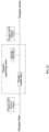
- the weighing monitoring unit may mainly include the weighing sensor, a first CPU, a signal processor, a first display module, the first Bluetooth communication module and a first alarm module.
- An output terminal of the weighing sensor may be connected to an input terminal of the signal processor.
- the output terminal of the signal processor may be connected to the first CPU.
- the first Bluetooth communication module may be provided on the first CPU.
- An output terminal of the first CPU may be connected to the first display module and the first alarm module.
- the first display module may include a measurement liquid crystal display and a key mounted on the base.
- the base may be further provided with a charging port thereon.
- the liquid bottle may include a bottle body, a bottle cap, an overflow-proof protection mechanism and a full liquid protection mechanism.
- the overflow-proof protection mechanism may include an overflow-proof plug and a splash-proof baffle.
- the bottle cap may be arranged on the bottle body and provided with a liquid inlet and a negative pressure port.
- the overflow-proof plug may be arranged at the negative pressure port at a bottom of the bottle cap.
- the splash-proof baffle may be arranged between the overflow-proof plug and the liquid inlet.
- the full liquid protection mechanism may include a photoelectric sensor arranged on the protection frame and connected with the first CPU.
- the overflow-proof plug may include a conical floating head, a connecting rod, a float silicone head and a float basket.
- the float basket is mounted at a lower end of the negative pressure port
- the connecting rod may be mounted to the float basket via the float silicone head for limiting
- the conical floating head is provided at a lower end of the connecting rod.
- the system further includes a liquid-pipe fixing clamp made of rubber and plastic material
- the liquid-pipe fixing clamp includes a clamp head formed with a clamping slot and a mounting slide groove.
- the mounting slide groove is arranged on a back of the clamp head and clamped on the protection frame.
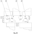
- the controller includes a housing, a pressure detection control module, a second CPU, a second display module and a key module.
- the housing is provided sequentially with a negative pressure inlet and an oxygen inlet on a wall of a rear housing of the housing.
- a bottom of the housing is provided sequentially with an oxygen outlet and a negative pressure outlet.
- the pressure detection control module is provided in the housing.
- Various corresponding electromagnetic valves of the pressure detection control module are connected to the negative pressure inlet, the oxygen inlet, the negative pressure outlet and the oxygen outlet via pipes, respectively.
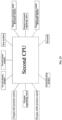
- the pressure detection control module, the second display module and the key module are respectively connected to the second CPU arranged inside the housing.
- a controller liquid crystal display of the second display module is embedded into a front end surface of a front housing of the housing.
- the key module is arranged below the second display module on the front housing.
- the pressure detection control module may include a negative pressure detection control unit.
- the negative pressure detection control unit may include a negative pressure regulating valve, a negative pressure inlet pressure sensor and a negative pressure outlet pressure sensor arranged on a valve plate.
- the negative pressure regulating valve may include a negative pressure intake valve, a negative pressure gulp valve, and a first vent valve.
- the negative pressure intake valve may be connected in series with the first vent valve and in parallel to the negative pressure gulp valve.
- a negative-pressure-inlet pressure sensor may be arranged on a pipe between the negative pressure inlet and the negative pressure regulating valve.
- a negative-pressure-outlet pressure sensor may be arranged on a pipe between the negative pressure regulating valve and the negative pressure outlet.
- the negative pressure regulating valve, the negative-pressure-inlet pressure sensor and the negative-pressure-outlet pressure sensor each may be connected to the second CPU.
- the pressure detection control module may further include an oxygen detection control unit.
- the oxygen detection control unit may include an oxygen regulating valve, an oxygen-inlet pressure sensor and an oxygen-outlet pressure sensor arranged on the valve plate.
- the oxygen regulating valve may include an oxygen intake valve and a second vent valve connected in series.
- An oxygen-inlet pressure sensor may be arranged on a pipe between the oxygen-inlet and the oxygen regulating valve.
- An oxygen-outlet pressure sensor may be arranged on a pipe between the oxygen regulating valve and the oxygen outlet.
- the oxygen regulating valve, the oxygen-inlet pressure sensor and the oxygen-outlet pressure sensor each may be connected to the second CPU.
- the negative pressure intake valve of the negative pressure regulating valve may include one negative pressure intake valve or more negative pressure intake valves connected in parallel.
- a sealing device may be provided at each valve port of the negative pressure regulating valve and the oxygen regulating valve.
- the system further includes an electronic overflow-proof module.
- the electronic overflow-proof module may include an overflow-proof device, an electrode circuit board, electrodes and an overflow-proof bottle.
- the overflow-proof device may be provided at the negative pressure outlet.
- Two electrodes may be mounted on the overflow-proof device and connected to the electrode circuit board.
- the electrode circuit board may be connected with the second CPU.
- the overflow-proof bottle covering an exterior of the electrodes may be arranged at the negative pressure outlet.
- a negative pressure air nozzle which is mounted by means of a sealing device may be provided on a bottle body of the overflow-proof bottle.
- the system may further include a second alarm module comprising an LED light covered by the overflow-proof bottle and a buzzer in the housing, and the LED light and the buzzer may be both connected to the second CPU.
- a second alarm module comprising an LED light covered by the overflow-proof bottle and a buzzer in the housing, and the LED light and the buzzer may be both connected to the second CPU.
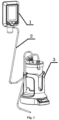
- a multifunctional central suction system capable of remote monitoring is configured to include a flow measurement device 3 and a controller 1, a negative pressure port on the flow measurement device is connected to a negative pressure air nozzle 39 of the controller via a gas pipe 2.
- the flow measurement device includes a measurement mechanism and a liquid bottle 12.
- the negative pressure port is arranged on the liquid bottle, and the measurement mechanism is provided with a first Bluetooth communication module.
- the controller is provided therein with a communication module including a second Bluetooth communication module and a WiFi communication module.
- the first Bluetooth communication module of the measurement mechanism is in communication connection with the second Bluetooth communication module of the controller.
- a model number of the second Bluetooth communication module is DX-BT05, and a model number of the WiFi communication module is ESP8266MOD.
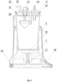
- the measurement mechanism of the flow measurement device includes a base 8, a weighing monitoring unit, a bracket 7 and a battery 24.
- the weighing monitoring unit is powered by the battery arranged in the base.
- a weighing sensor of the weighing monitoring unit is provided on the base.
- the bracket is provided above the weighing sensor.
- Baffle plates 6 are evenly disposed at intervals circumferentially on an upper end surface of a bracket body of the bracket; and an area surrounded by the baffle plates forms a liquid bottle mounting area. The liquid bottle is mounted in the liquid bottle mounting area.
- the base is a groove-type base
- a guard plate 34 protruding upward is provided at a first side in a groove of the groove-type base
- the weighing sensor 17 is provided at a second side opposite to the first side in the groove and is arranged perpendicularly to the guard plate in a plane.
- a height of the weighing sensor is higher than a height of the guard plate, a height difference between the weighting sensor and the guard plate is 1mm.
- the bracket includes an upper supporting plate 30 and a lower supporting plate 31 provided in one piece.
- a bottom of the lower supporting plate is provided with limiting protrusions 33 assembled at two ends of the weighing sensor.
- a mounting groove 16 is arranged in a middle of the upper supporting plate.
- Mounting through holes 32 leading to the lower supporting plate are arranged in the mounting groove and located between two limiting protrusions.
- the bracket is assembled with the weighing sensor in the base via a screw passing through the mounting through-hole.
- the baffle plates adapted to an outer diameter of a bottom of the liquid bottle are arranged circumferentially on the upper supporting plate.
- the measurement mechanism further includes a protection frame 5.
- the protection frame includes a shell integrally formed with the base, a protection frame body 27 arranged on an inner wall of the shell, and a guard ring 29 arranged within the protection frame body via a mounting block 28.
- the weighing monitoring unit includes the weighing sensor, a first CPU 18, a signal processor, a first display module, the first Bluetooth communication module and a first alarm module.
- An output terminal of the weighing sensor is connected to an input terminal of the signal processor.
- the output terminal of the signal processor is connected to the first CPU.
- the first Bluetooth communication module is further provided on the first CPU.
- An output terminal of the first CPU is connected to the first display module and the first alarm module.
- the first display module includes a measurement liquid crystal display 10 and a key 9 mounted on the base.
- the base is further provided with a charging port 19.
- the liquid bottle includes a bottle body, a bottle cap 4, an overflow-proof protection mechanism and a full liquid protection mechanism.
- the overflow-proof protection mechanism includes an overflow-proof plug and a splash-proof baffle 15.
- the bottle cap is arranged on the bottle body, and provided with a liquid inlet 14 and a negative pressure port 13.
- the overflow-proof plug is arranged at the negative pressure port at a bottom of the bottle cap.
- the splash-proof baffle is arranged between the overflow-proof plug and the liquid inlet.
- the full liquid protection mechanism includes a photoelectric sensor 23 arranged on the protection frame and connected with the first CPU.
- the overflow-proof plug includes a conical floating head 20, a connecting rod 21, a float silicone head 22 and a float basket 55.
- the float basket is mounted at a lower end of the negative pressure port.
- the connecting rod is mounted to the float basket via the float silicone head for limiting.
- the conical floating head integrally formed with the connecting rod is provided at a lower end of the connecting rod.
- the system further includes a liquid pipe fixing clamp 11 made of rubber and plastic material.
- the liquid pipe fixing clamp includes a clamp head 26 formed with a clamping slot, and a mounting slide groove 25 arranged on a back of the clamp head and clamped on the protection frame.
- the controller includes a housing, a pressure detection control module, a second CPU 52, a second display module and a key module 54.
- a negative pressure inlet 42 and an oxygen inlet 43 is sequentially provided on a rear wall of the housing; an oxygen outlet 37 and a negative pressure outlet are sequentially provided at a bottom of the housing.
- the pressure detection control module is provided in the housing.
- Various corresponding electromagnetic valves of the pressure detection control module are connected to the corresponding negative pressure inlet, the corresponding oxygen inlet, the corresponding negative pressure outlet and the corresponding oxygen outlet via pipes, respectively.
- the pressure detection control module, the second display module and the key module are respectively connected to the second CPU arranged inside the housing.
- a controller liquid crystal display 35 of the second display module is embedded into a front end surface of a front housing of the housing.
- the key module is arranged below the second display module on the front housing.
- the key module includes a key circuit board and a key.
- a model number of the second CPU is an STM32 series.
- the pressure detection control module includes an electromagnetic valve group 41, a negative-pressure-inlet pressure sensor 49, a negative-pressure-outlet pressure sensor 48, an oxygen-inlet pressure sensor 50 and an oxygen-outlet pressure sensor 51.
- a silencer 40 is provided in the electromagnetic valve group 41 including a valve plate, a negative pressure regulating valve and an oxygen regulating valve provided on the valve plate.
- the negative pressure regulating valve includes a negative pressure intake valve 63, a negative pressure gulp valve 57, and a first vent valve 56.
- the negative pressure intake valve is connected in series with the first vent valve 56.
- the negative pressure gulp valve is connected in parallel to the negative pressure intake valve.
- the negative-pressure-inlet pressure sensor is provided on a pipe between the negative pressure inlet and a negative-pressure-inlet connector 62 at the negative pressure regulating valve.
- the negative-pressure-outlet pressure sensor is provided on a pipe between a negative-pressure-outlet connector 61 at the negative pressure regulating valve and the negative pressure outlet.
- the oxygen regulating valve includes an oxygen intake valve 58 and a second vent valve 60 connected in series.
- the oxygen-inlet pressure sensor is provided on a pipe between the oxygen inlet and the oxygen regulating valve.
- the oxygen-outlet pressure sensor is provided on a pipe between the oxygen outlet connector 59 at the oxygen regulating valve and the oxygen outlet.
- the negative pressure regulating valve, the oxygen regulating valve, the negative-pressure-inlet pressure sensor, the negative-pressure-outlet pressure sensor, the oxygen-inlet pressure sensor and the oxygen-outlet pressure sensor each are connected to the second CPU.
- the negative pressure intake valve of the negative pressure regulating valve includes one negative pressure intake valve or more negative pressure intake valves connected in parallel.
- a first end of the negative pressure regulating valve is connected to the negative pressure inlet via a pipe, and a second end of the negative pressure regulating valve is connected to the negative pressure outlet via a pipe.
- a sealing gasket 64 is provided at each valve port of the negative pressure regulating valve and the oxygen regulating valve.
- the system further includes an electronic overflow-proof module.
- the electronic overflow-proof module includes an overflow-proof device 46, an electrode circuit board 45, electrodes 47 and an overflow-proof bottle 38.
- the overflow-proof device is provided at the negative pressure outlet.
- the electrodes are mounted on the overflow-proof device and connected to the electrode circuit board.
- the electrode circuit board is connected with the second CPU.
- the overflow-proof bottle 38 covering an exterior of the electrodes is arranged at the negative pressure outlet.
- a negative pressure air nozzle is mounted on a bottle body of the overflow-proof bottle via an annular sealing ring 65.
- the overflow-proof device 46 is an overflow-proof valve.
- the system further includes a second alarm module including an LED light 53 covered by the overflow-proof bottle and a buzzer in the housing, and the LED light and the buzzer are both connected to the second CPU.
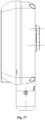
- the housing includes a front housing 36 and a rear housing 44 that are connected via screws.
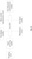
- the controller can acquire data from the flow measurement device via the first Bluetooth communication module and the second Bluetooth communication module provided, and transmit the data to a terminal such as Nurses Station via a WiFi module on the controller, facilitating a nurse to monitor and ensuring safety of a patient during drainage.
Landscapes
- Health & Medical Sciences (AREA)
- Heart & Thoracic Surgery (AREA)
- Public Health (AREA)
- Animal Behavior & Ethology (AREA)
- Veterinary Medicine (AREA)
- General Health & Medical Sciences (AREA)
- Life Sciences & Earth Sciences (AREA)
- Engineering & Computer Science (AREA)
- Vascular Medicine (AREA)
- Anesthesiology (AREA)
- Biomedical Technology (AREA)
- Hematology (AREA)
- Rehabilitation Therapy (AREA)
- Physical Education & Sports Medicine (AREA)
- Pain & Pain Management (AREA)
- Epidemiology (AREA)
- External Artificial Organs (AREA)
- Details Of Rigid Or Semi-Rigid Containers (AREA)
Claims (16)
- Ein multifunktionales zentrales Absaugsystem, das zur Fernüberwachung geeignet ist, mit einer Durchflussmessvorrichtung (3) und einer Steuerung (1), wobei ein Unterdruckanschluss (13) der Durchflussmessvorrichtung (3) über eine Gasleitung (2) mit einer Unterdruckluftdüse (39) der Steuerung (1) verbunden ist, die Durchflussmessvorrichtung (3) einen Messmechanismus und eine Flüssigkeitsflasche (12) umfasst, der Unterdruckanschluss (13) an der Flüssigkeitsflasche (12) angeordnet ist; der Messmechanismus ist mit einem ersten Bluetooth-Kommunikationsmodul versehen, ein Kommunikationsmodul, das ein zweites Bluetooth-Kommunikationsmodul und ein WiFi-Kommunikationsmodul umfasst, ist in der Steuerung (1) bereitgestellt; das erste Bluetooth-Kommunikationsmodul am Messmechanismus steht in Kommunikationsverbindung mit dem zweiten Bluetooth-Kommunikationsmodul in der Steuerung (1);
wobei die Steuerung (1) ein Gehäuse, ein Druckerkennungs-Steuermodul, eine zweite CPU (52), ein zweites Anzeigemodul und ein Tastenmodul (54) umfasst; ein Unterdruckeinlass (42) und ein Sauerstoffeinlass (43) sind nacheinander an einer Wand eines hinteren Gehäuses (44) des Gehäuses bereitgestellt; und ein Sauerstoffauslass (37) und ein Unterdruckauslass sind nacheinander an einem Boden des Gehäuses bereitgestellt; das Druckerkennungs-Steuermodul ist im Gehäuse bereitgestellt, verschiedene entsprechende elektromagnetische Ventile des Druckerkennungs-Steuermoduls sind mit dem Unterdruckeinlass (42), dem Sauerstoffeinlass (43), dem Unterdruckauslass und dem Sauerstoffauslass (37) jeweils über eine Leitung verbunden; das Druckerkennungs-Steuermodul, das zweite Anzeigemodul und das Tastenmodul (54) sind jeweils mit der zweiten CPU (52) verbunden, die im Inneren des Gehäuses angeordnet ist, das zweite Anzeigemodul ist in eine vordere Endfläche eines vorderen Gehäuses (36) des Gehäuses eingebettet, das Tastenmodul (54) ist unterhalb des zweiten Anzeigemoduls an dem vorderen Gehäuse (36) angeordnet. - Das multifunktionale zentrale Absaugsystem nach Anspruch 1, wobei der Messmechanismus der Durchflussmessvorrichtung (3) einen Fuß (8), eine Wägeüberwachungseinheit, einen Halterung (7) und eine Batterie (24) umfasst, die Wägeüberwachungseinheit von der im Fuß (8) angeordneten Batterie (24) mit Strom versorgt wird, ein Wägesensor (17) der Wägeüberwachungseinheit am Fuß (8) bereitgestellt ist, die Halterung (7) oberhalb des Wägesensors (17) bereitgestellt ist, und Ablenkplatten (6) gleichmäßig und in Umfangsrichtung in einem Abstand auf einer oberen Endfläche eines Halterungskörpers der Halterung (7) angeordnet sind, ein von den Ablenkplatten (6) umgebener Bereich bildet einen Montagebereich für die Flüssigkeitsflasche (12), die Flüssigkeitsflasche (12) in dem Montagebereich montiert ist.
- Das multifunktionale zentrale Ansaugsystem nach Anspruch 2, wobei der Fuß (8) ein Nutenfuß ist, eine nach oben vorstehende Schutzplatte (34) an einer ersten Seite in einer Nut des Nutenfußes bereitgestellt ist, der Wägesensor (17) an einer zweiten, der ersten Seite gegenüberliegenden Seite in der Nut bereitgestellt ist und senkrecht zur Schutzplatte (34) in einer Ebene angeordnet ist, und eine Höhe des Wägesensors (17) höher als eine Höhe der Schutzplatte (34) ist.
- Das multifunktionale zentrale Absaugsystem nach Anspruch 2, wobei die Halterung (7) eine obere Trägerplatte (30) und eine untere Trägerplatte (31) umfasst, die einstückig beschaffen sind, ein Boden der unteren Trägerplatte (31) mit Begrenzungsvorsprüngen (33) versehen ist, die an zwei Enden des Wägesensors (17) montiert sind, eine Montagenut (16) in einer Mitte der oberen Trägerplatte (30) angeordnet ist, in der Montagenut (16) Montagedurchgangslöcher (32) zur Durchführung zur unteren Tragplatte (31) angeordnet sind und sich zwischen zwei Begrenzungsvorsprüngen (33) befinden, der Bügel (7) mit dem Wägesensor im Fuß (8) mittels durch die Montagedurchgangslöcher (32) geführten Schrauben montiert ist, die an einen Außendurchmesser eines Bodens der Flüssigkeitsflasche (12) angepassten Ablenkplatten (6) umlaufend auf der oberen Tragplatte (30) angeordnet sind.
- Das multifunktionale zentrale Absaugsystem nach Anspruch 2, wobei der Messmechanismus ferner einen Schutzrahmen (5) umfasst; der Schutzrahmen (5) umfasst eine einstückig mit dem Fuß (8) ausgebildete Schale, einen Schutzrahmenkörper (27), der an einer Innenwand der Schale angeordnet ist, und einen Schutzring (29), der an einem Innenumfang des Schutzrahmenkörpers (27) über einen Montageblock (28) angeordnet ist.
- Das multifunktionale zentrale Absaugsystem nach Anspruch 2, wobei die Wägeüberwachungseinheit den Wägesensor (17), eine erste CPU (18), einen Signalprozessor, ein erstes Anzeigemodul, das erste Bluetooth-Kommunikationsmodul und ein erstes Alarmmodul umfasst, ein Ausgangsanschluss des Wägesensors (17) mit einem Eingangsanschluss des Signalprozessors verbunden ist, ein Ausgangsanschluss des Signalprozessors mit der ersten CPU (18) verbunden ist, das erste Bluetooth-Kommunikationsmodul auf der ersten CPU (18) angeordnet ist, ein Ausgangsanschluss der ersten CPU (18) mit dem ersten Anzeigemodul und dem ersten Alarmmodul verbunden ist, das erste Anzeigemodul eine Mess-Flüssigkristallanzeige (10) und eine auf dem Fuß (8) angebrachte Taste (9) umfasst.
- Das multifunktionale zentrale Absaugsystem nach Anspruch 2, wobei der Fuß (8) ferner mit einem Ladeanschluss (19) versehen ist.
- Das multifunktionale zentrale Absaugsystem nach Anspruch 1, wobei die Flüssigkeitsflasche (12) einen Flaschenkörper, eine Flaschenkappe (4), einen überlaufsicheren Schutzmechanismus und einen Vollflüssigkeitsschutzmechanismus umfasst, wobei der überlaufsichere Schutzmechanismus einen überlaufsicheren Stopfen und ein spritzsicheres Ablenkblech (15) umfasst, die Flaschenkappe (4) mit einem Flüssigkeitseinlass (14) und der Unterdrucköffnung (13) daran versehen ist, der überlaufsichere Stopfen an der Unterdrucköffnung (13) an einem Boden der Flaschenkappe (4) angeordnet ist, das spritzsichere Ablenkblech (15) zwischen dem überlaufsicheren Stopfen und dem Flüssigkeitseinlass (14) angeordnet ist; der Vollflüssigkeitsschutzmechanismus umfasst einen fotoelektrischen Sensor (23), der auf dem Schutzrahmen (5) angeordnet und mit der ersten CPU (18) verbunden ist.
- Das multifunktionale zentrale Absaugsystem nach Anspruch 8, wobei der überlaufsichere Stopfen einen konischen Schwimmkopf (20), eine Verbindungsstange (21), einen Schwimmsilikonkopf (22) und einen Schwimmerkorb (55) umfasst; der Schwimmerkorb (55) ist an einem unteren Ende des Unterdruckanschlusses (13) angebracht, die Verbindungsstange (21) ist über den Schwimmsilikonkopf (22) zur Begrenzung an dem Schwimmerkorb (55) angebracht und ist an einem unteren Ende der Verbindungsstange (21) mit dem konischen Schwimmkopf (20) versehen.
- Das multifunktionale zentrale Absaugsystem nach Anspruch 5, ferner aufweisend eine Flüssigkeitsleitungsbefestigungsschelle (11), wobei die Flüssigkeitsleitungsbefestigungsschelle (11) einen mit einem Klemmschlitz und einer auf einer Rückseite des Schellenkopfes (26) angeordneten und am Schutzrahmen (5) festgeklemmten Befestigungsgleitnut (25) ausgebildeten Schellenkopf (26) aufweist.
- Das multifunktionale zentrale Absaugsystem nach Anspruch 1, wobei das Tastenmodul (54) eine Tastenplatine und eine Taste umfasst; das Druckerkennungs-Steuermodul umfasst eine Unterdruckerkennungs-Steuereinheit, die ein Unterdruck-Regelventil, einen Unterdruck-Eingangsdrucksensor (49) und einen Unterdruck-Ausgangsdrucksensor (48) umfasst, die auf einer Ventilplatte angeordnet sind; das Unterdruck-Regelventil umfasst ein Unterdruck-Einlassventil (63), ein Unterdruck-Luftaufnahmeventil (57) und ein erstes Entlüftungsventil (56); das Unterdruck-Einlassventil (63) ist in Reihe mit dem ersten Entlüftungsventil (56) und parallel zum Unterdruck-Luftaufnahmeventil (57) geschaltet; der Unterdruckeinlass-Drucksensor (49) ist an einer Leitung zwischen dem Unterdruckeinlass (42) und dem Unterdruck-Regelventil angeordnet; der Unterdruck-Ausgangs-Drucksensor (48) ist an einer Leitung zwischen dem Unterdruck-Regelventil und dem Unterdruck-Ausgang angeordnet; das Unterdruck-Regelventil, der Unterdruck-Eingangs-Drucksensor (49) und der Unterdruck-Ausgangs-Drucksensor (48) sind jeweils mit der zweiten CPU (52).
- Das multifunktionale zentrale Absaugsystem nach Anspruch 11, wobei das Druckerkennungs-Steuermodul ferner eine Sauerstofferkennungs-Steuereinheit umfasst, die ein Sauerstoff-Regelventil, einen Sauerstoff-Eingangsdrucksensor (50) und einen Sauerstoff-Ausgangsdrucksensor (51) umfasst, die auf der Ventilplatte angeordnet sind; das Sauerstoff-Regelventil umfasst ein Sauerstoff-Einlassventil (58) und ein zweites Entlüftungsventil (60), die in Reihe geschaltet sind; der Sauerstoff-Eingangsdrucksensor (50) ist an einer Leitung zwischen dem Sauerstoffeinlass (43) und dem Sauerstoff-Regelventil angeordnet; der Sauerstoff-Ausgangsdrucksensor (51) ist an einer Leitung zwischen dem Sauerstoff-Regelventil und dem Sauerstoffauslass (37) angeordnet; das Sauerstoff-Regelventil, der Sauerstoff-Eingangsdrucksensor (50) und der Sauerstoff-Ausgangsdrucksensor (51) sind jeweils mit der zweiten CPU (52) verbunden.
- Das multifunktionale zentrale Absaugsystem nach Anspruch 11, wobei das Unterdruck-Einlassventil (63) des Unterdruck-Regelventils ein Unterdruck-Einlassventil (63) oder mehrere parallel geschaltete Unterdruck-Einlassventile (63) umfasst.
- Das multifunktionale zentrale Absaugsystem nach Anspruch 11 oder 12, wobei an jedem Ventilanschluss des Unterdruck-Regelventils und des Sauerstoff-Regelventils eine Dichtungseinrichtung bereitgestellt ist.
- Das multifunktionale zentrale Absaugsystem nach Anspruch 1, ferner umfassend ein elektronisches Überlaufsicherungsmodul; das elektronische Überlaufsicherungsmodul umfasst eine Überlaufsicherungseinrichtung (46), eine Elektrodenplatine (45), Elektroden (47) und eine überlaufsichere Flasche (38); die Überlaufsicherungseinrichtung (46) ist am Unterdruckausgang angeordnet; zwei Elektroden (47) sind auf der Überlaufsicherungseinrichtung (46) angebracht und mit der Elektrodenplatine (45) verbunden; die Elektrodenplatine (45) ist mit der zweiten CPU (52) verbunden, und die überlaufsichere Flasche (38), die eine Außenseite der Elektroden abdeckt, ist am Unterdruckausgang angeordnet, die Unterdruckluftdüse (39) ist über eine Dichtungsvorrichtung an einem Flaschenkörper der überlaufsicheren Flasche (38) bereitgestellt.
- Das multifunktionale zentrale Absaugsystem nach Anspruch 15, ferner aufweisend ein zweites Alarmmodul, wobei das zweite Alarmmodul eine von der überlaufsicheren Flasche (38) abgedeckte LED-Leuchte (53) und einen Summer im Gehäuse umfasst; und die LED-Leuchte (53) und der Summer beide mit der zweiten CPU (52) verbunden sind.
Applications Claiming Priority (2)
| Application Number | Priority Date | Filing Date | Title |
|---|---|---|---|
| CN201910460436.1A CN110251741B (zh) | 2019-05-30 | 2019-05-30 | 一种能够实现远程监控的多功能中央吸引系统 |
| PCT/CN2020/090813 WO2020238675A1 (zh) | 2019-05-30 | 2020-05-18 | 一种能够实现远程监控的多功能中央吸引系统 |
Publications (4)
| Publication Number | Publication Date |
|---|---|
| EP3851133A1 EP3851133A1 (de) | 2021-07-21 |
| EP3851133A4 EP3851133A4 (de) | 2022-05-04 |
| EP3851133B1 true EP3851133B1 (de) | 2024-12-25 |
| EP3851133C0 EP3851133C0 (de) | 2024-12-25 |
Family
ID=67915946
Family Applications (1)
| Application Number | Title | Priority Date | Filing Date |
|---|---|---|---|
| EP20813853.7A Active EP3851133B1 (de) | 2019-05-30 | 2020-05-18 | Multifunktionales zentrales saugsystem mit fähigkeit zur durchführung einer fernüberwachung |
Country Status (4)
| Country | Link |
|---|---|
| US (1) | US12343466B2 (de) |
| EP (1) | EP3851133B1 (de) |
| CN (1) | CN110251741B (de) |
| WO (1) | WO2020238675A1 (de) |
Families Citing this family (5)
| Publication number | Priority date | Publication date | Assignee | Title |
|---|---|---|---|---|
| CN110251741B (zh) | 2019-05-30 | 2024-11-19 | 天津市同业科技发展有限公司 | 一种能够实现远程监控的多功能中央吸引系统 |
| CN112999442A (zh) * | 2021-02-22 | 2021-06-22 | 南京市儿童医院 | 一种儿童外科感染负压封闭吸引系统 |
| CN116511200A (zh) * | 2023-05-09 | 2023-08-01 | 福建星云电子股份有限公司 | 一种化成分容负压模组清洗系统及方法 |
| CN117031466B (zh) * | 2023-10-09 | 2023-12-08 | 乐山师范学院 | 一种基于雷达监测山地旅游景区的设备及方法 |
| CN118787496B (zh) * | 2024-09-14 | 2024-11-22 | 天津市顺博医疗设备有限公司 | 一种镇痛修复系统 |
Family Cites Families (20)
| Publication number | Priority date | Publication date | Assignee | Title |
|---|---|---|---|---|
| US6764462B2 (en) * | 2000-11-29 | 2004-07-20 | Hill-Rom Services Inc. | Wound treatment apparatus |
| JP4441214B2 (ja) * | 2003-08-26 | 2010-03-31 | 帝人株式会社 | 酸素濃縮装置 |
| EP1909863A1 (de) * | 2005-07-24 | 2008-04-16 | Carmeli Adahan | Wundverschluss und drainagesystem |
| DK1960014T3 (en) * | 2005-12-14 | 2017-01-09 | Stryker Corp | Medical / surgical waste collection and disposal system |
| US20100022990A1 (en) * | 2008-07-25 | 2010-01-28 | Boehringer Technologies, L.P. | Pump system for negative pressure wound therapy and improvements thereon |
| CN101810534A (zh) * | 2009-02-24 | 2010-08-25 | 广州市忆典医疗器械有限公司 | 一种新型正负压体外反博装置 |
| CN201379828Y (zh) * | 2009-04-17 | 2010-01-13 | 天津市同业科技发展有限公司 | 负压吸引器的防溢流装置 |
| CN201871002U (zh) | 2010-09-03 | 2011-06-22 | 惠州市华阳多媒体电子有限公司 | 可检测并显示渗出液体积的负压伤口治疗系统 |
| CN201959393U (zh) * | 2010-12-20 | 2011-09-07 | 惠州市华阳多媒体电子有限公司 | 可检测伤口渗出液重量的负压伤口治疗系统 |
| WO2013123022A1 (en) * | 2012-02-13 | 2013-08-22 | Integrated Healing Technologies | Multi-modal wound treatment apparatus |
| CN103528636B (zh) | 2013-10-21 | 2018-02-23 | 天津市同业科技发展有限公司 | 负压固定容积式液量动态测量装置 |
| EP3659638B1 (de) * | 2014-07-31 | 2026-01-07 | Smith & Nephew, Inc. | Systeme und verfahren zur anwendung einer therapie mit reduziertem druck |
| EP3009364A1 (de) * | 2014-10-13 | 2016-04-20 | Series Nemo, SL | Glasflasche |
| EP4059530B1 (de) * | 2016-05-13 | 2025-07-23 | Smith & Nephew, Inc. | Automatische wundenverbindungsdetektion in unterdruckwundtherapiesystemen |
| CN106110417B (zh) * | 2016-08-16 | 2018-02-13 | 南通市第一人民医院 | 一种防止空吸的吸引装置 |
| US20190381220A1 (en) * | 2017-01-23 | 2019-12-19 | Kci Licensing, Inc. | Negative pressure systems for the management of pleural effusion |
| US11589888B2 (en) * | 2017-12-28 | 2023-02-28 | Cilag Gmbh International | Method for controlling smart energy devices |
| US10863840B2 (en) * | 2018-04-09 | 2020-12-15 | Innovative Drive | Anti-sloshing liquid-retaining bottles |
| CN110251741B (zh) | 2019-05-30 | 2024-11-19 | 天津市同业科技发展有限公司 | 一种能够实现远程监控的多功能中央吸引系统 |
| CN211461421U (zh) * | 2019-05-30 | 2020-09-11 | 天津市同业科技发展有限公司 | 一种能够实现远程监控的多功能中央吸引系统 |
-
2019
- 2019-05-30 CN CN201910460436.1A patent/CN110251741B/zh active Active
-
2020
- 2020-05-18 EP EP20813853.7A patent/EP3851133B1/de active Active
- 2020-05-18 US US17/417,926 patent/US12343466B2/en active Active
- 2020-05-18 WO PCT/CN2020/090813 patent/WO2020238675A1/zh not_active Ceased
Also Published As
| Publication number | Publication date |
|---|---|
| CN110251741A (zh) | 2019-09-20 |
| EP3851133A1 (de) | 2021-07-21 |
| EP3851133A4 (de) | 2022-05-04 |
| EP3851133C0 (de) | 2024-12-25 |
| CN110251741B (zh) | 2024-11-19 |
| US20220088284A1 (en) | 2022-03-24 |
| US12343466B2 (en) | 2025-07-01 |
| WO2020238675A1 (zh) | 2020-12-03 |
Similar Documents
| Publication | Publication Date | Title |
|---|---|---|
| US12343466B2 (en) | Multifunctional central suction system capable of remote monitoring | |
| CN103736163A (zh) | 基于无线传感器网络的智能点滴系统 | |
| CN205494560U (zh) | 基于wifi的简易输液监测报警装置 | |
| CN203355067U (zh) | 呼吸机配套用气管切开插管气囊压力连续监测控制仪 | |
| CN104857594B (zh) | 气泵式集成输液设备 | |
| CN111467638A (zh) | 一种具有血氧饱和度控制功能的智能氧疗制氧机 | |
| CN211461421U (zh) | 一种能够实现远程监控的多功能中央吸引系统 | |
| CN204840508U (zh) | 一种红外感应式输液报警装置 | |
| CN104857595B (zh) | 气泵式便携输液设备 | |
| CN215023923U (zh) | 一种医用输液泵 | |
| CN221411878U (zh) | 一种临床护理智能输液管理器 | |
| CN110201249B (zh) | 一种用于负压吸引的流量测量装置 | |
| CN212262060U (zh) | 一种输液报警装置 | |
| CN206404109U (zh) | 一种用于自动报警的输液架 | |
| CN211461420U (zh) | 一种用于负压吸引的流量测量装置 | |
| CN215915836U (zh) | 一种甲乳外科术后引流液监测装置 | |
| CN214970342U (zh) | 可控滴速输液报警器 | |
| CN110302439B (zh) | 一种负压及/或氧气输出稳定的多功能中央吸引控制器 | |
| CN211301474U (zh) | 一种多路点滴输液系统 | |
| CN108815595A (zh) | 一种消化内科临床用肠胃减压装置 | |
| CN211461419U (zh) | 一种负压及/或氧气输出稳定的多功能中央吸引控制器 | |
| CN210963375U (zh) | 一种多功能智能输液报警器 | |
| CN215023892U (zh) | 一种用于精密输液监控的便携装置 | |
| CN215134358U (zh) | 一种医用多功能负压引流装置 | |
| CN205569437U (zh) | 便携式安全输液装置 |
Legal Events
| Date | Code | Title | Description |
|---|---|---|---|
| STAA | Information on the status of an ep patent application or granted ep patent |
Free format text: STATUS: THE INTERNATIONAL PUBLICATION HAS BEEN MADE |
|
| PUAI | Public reference made under article 153(3) epc to a published international application that has entered the european phase |
Free format text: ORIGINAL CODE: 0009012 |
|
| STAA | Information on the status of an ep patent application or granted ep patent |
Free format text: STATUS: REQUEST FOR EXAMINATION WAS MADE |
|
| 17P | Request for examination filed |
Effective date: 20210413 |
|
| AK | Designated contracting states |
Kind code of ref document: A1 Designated state(s): AL AT BE BG CH CY CZ DE DK EE ES FI FR GB GR HR HU IE IS IT LI LT LU LV MC MK MT NL NO PL PT RO RS SE SI SK SM TR |
|
| A4 | Supplementary search report drawn up and despatched |
Effective date: 20220407 |
|
| RIC1 | Information provided on ipc code assigned before grant |
Ipc: A61M 35/00 20060101ALI20220401BHEP Ipc: A61M 1/00 20060101AFI20220401BHEP |
|
| DAV | Request for validation of the european patent (deleted) | ||
| DAX | Request for extension of the european patent (deleted) | ||
| GRAP | Despatch of communication of intention to grant a patent |
Free format text: ORIGINAL CODE: EPIDOSNIGR1 |
|
| STAA | Information on the status of an ep patent application or granted ep patent |
Free format text: STATUS: GRANT OF PATENT IS INTENDED |
|
| INTG | Intention to grant announced |
Effective date: 20240924 |
|
| GRAS | Grant fee paid |
Free format text: ORIGINAL CODE: EPIDOSNIGR3 |
|
| GRAA | (expected) grant |
Free format text: ORIGINAL CODE: 0009210 |
|
| STAA | Information on the status of an ep patent application or granted ep patent |
Free format text: STATUS: THE PATENT HAS BEEN GRANTED |
|
| AK | Designated contracting states |
Kind code of ref document: B1 Designated state(s): AL AT BE BG CH CY CZ DE DK EE ES FI FR GB GR HR HU IE IS IT LI LT LU LV MC MK MT NL NO PL PT RO RS SE SI SK SM TR |
|
| REG | Reference to a national code |
Ref country code: GB Ref legal event code: FG4D |
|
| REG | Reference to a national code |
Ref country code: CH Ref legal event code: EP |
|
| REG | Reference to a national code |
Ref country code: DE Ref legal event code: R096 Ref document number: 602020043768 Country of ref document: DE |
|
| REG | Reference to a national code |
Ref country code: IE Ref legal event code: FG4D |
|
| U01 | Request for unitary effect filed |
Effective date: 20250121 |
|
| U07 | Unitary effect registered |
Designated state(s): AT BE BG DE DK EE FI FR IT LT LU LV MT NL PT RO SE SI Effective date: 20250127 |
|
| PG25 | Lapsed in a contracting state [announced via postgrant information from national office to epo] |
Ref country code: NO Free format text: LAPSE BECAUSE OF FAILURE TO SUBMIT A TRANSLATION OF THE DESCRIPTION OR TO PAY THE FEE WITHIN THE PRESCRIBED TIME-LIMIT Effective date: 20250325 |
|
| PG25 | Lapsed in a contracting state [announced via postgrant information from national office to epo] |
Ref country code: GR Free format text: LAPSE BECAUSE OF FAILURE TO SUBMIT A TRANSLATION OF THE DESCRIPTION OR TO PAY THE FEE WITHIN THE PRESCRIBED TIME-LIMIT Effective date: 20250326 |
|
| PG25 | Lapsed in a contracting state [announced via postgrant information from national office to epo] |
Ref country code: RS Free format text: LAPSE BECAUSE OF FAILURE TO SUBMIT A TRANSLATION OF THE DESCRIPTION OR TO PAY THE FEE WITHIN THE PRESCRIBED TIME-LIMIT Effective date: 20250325 |
|
| U20 | Renewal fee for the european patent with unitary effect paid |
Year of fee payment: 6 Effective date: 20250407 |
|
| PG25 | Lapsed in a contracting state [announced via postgrant information from national office to epo] |
Ref country code: SM Free format text: LAPSE BECAUSE OF FAILURE TO SUBMIT A TRANSLATION OF THE DESCRIPTION OR TO PAY THE FEE WITHIN THE PRESCRIBED TIME-LIMIT Effective date: 20241225 |
|
| PG25 | Lapsed in a contracting state [announced via postgrant information from national office to epo] |
Ref country code: PL Free format text: LAPSE BECAUSE OF FAILURE TO SUBMIT A TRANSLATION OF THE DESCRIPTION OR TO PAY THE FEE WITHIN THE PRESCRIBED TIME-LIMIT Effective date: 20241225 |
|
| PG25 | Lapsed in a contracting state [announced via postgrant information from national office to epo] |
Ref country code: ES Free format text: LAPSE BECAUSE OF FAILURE TO SUBMIT A TRANSLATION OF THE DESCRIPTION OR TO PAY THE FEE WITHIN THE PRESCRIBED TIME-LIMIT Effective date: 20241225 |
|
| PG25 | Lapsed in a contracting state [announced via postgrant information from national office to epo] |
Ref country code: IS Free format text: LAPSE BECAUSE OF FAILURE TO SUBMIT A TRANSLATION OF THE DESCRIPTION OR TO PAY THE FEE WITHIN THE PRESCRIBED TIME-LIMIT Effective date: 20250425 |
|
| PG25 | Lapsed in a contracting state [announced via postgrant information from national office to epo] |
Ref country code: SK Free format text: LAPSE BECAUSE OF FAILURE TO SUBMIT A TRANSLATION OF THE DESCRIPTION OR TO PAY THE FEE WITHIN THE PRESCRIBED TIME-LIMIT Effective date: 20241225 |
|
| PG25 | Lapsed in a contracting state [announced via postgrant information from national office to epo] |
Ref country code: CZ Free format text: LAPSE BECAUSE OF FAILURE TO SUBMIT A TRANSLATION OF THE DESCRIPTION OR TO PAY THE FEE WITHIN THE PRESCRIBED TIME-LIMIT Effective date: 20241225 |
|
| PLBE | No opposition filed within time limit |
Free format text: ORIGINAL CODE: 0009261 |
|
| STAA | Information on the status of an ep patent application or granted ep patent |
Free format text: STATUS: NO OPPOSITION FILED WITHIN TIME LIMIT |
|
| REG | Reference to a national code |
Ref country code: CH Ref legal event code: L10 Free format text: ST27 STATUS EVENT CODE: U-0-0-L10-L00 (AS PROVIDED BY THE NATIONAL OFFICE) Effective date: 20251105 |
|
| 26N | No opposition filed |
Effective date: 20250926 |
|
| REG | Reference to a national code |
Ref country code: CH Ref legal event code: H13 Free format text: ST27 STATUS EVENT CODE: U-0-0-H10-H13 (AS PROVIDED BY THE NATIONAL OFFICE) Effective date: 20251223 |
|
| PG25 | Lapsed in a contracting state [announced via postgrant information from national office to epo] |
Ref country code: CH Free format text: LAPSE BECAUSE OF NON-PAYMENT OF DUE FEES Effective date: 20250531 |
|
| GBPC | Gb: european patent ceased through non-payment of renewal fee |
Effective date: 20250518 |
|
| PG25 | Lapsed in a contracting state [announced via postgrant information from national office to epo] |
Ref country code: MC Free format text: LAPSE BECAUSE OF FAILURE TO SUBMIT A TRANSLATION OF THE DESCRIPTION OR TO PAY THE FEE WITHIN THE PRESCRIBED TIME-LIMIT Effective date: 20241225 |
|
| PG25 | Lapsed in a contracting state [announced via postgrant information from national office to epo] |
Ref country code: GB Free format text: LAPSE BECAUSE OF NON-PAYMENT OF DUE FEES Effective date: 20250518 |
|
| PG25 | Lapsed in a contracting state [announced via postgrant information from national office to epo] |
Ref country code: IE Free format text: LAPSE BECAUSE OF NON-PAYMENT OF DUE FEES Effective date: 20250518 |
|
| PG25 | Lapsed in a contracting state [announced via postgrant information from national office to epo] |
Ref country code: HR Free format text: LAPSE BECAUSE OF FAILURE TO SUBMIT A TRANSLATION OF THE DESCRIPTION OR TO PAY THE FEE WITHIN THE PRESCRIBED TIME-LIMIT Effective date: 20241225 |