EP3850308B1 - Navigation system for use in automomous tool and method for controlling autonomous tool - Google Patents
Navigation system for use in automomous tool and method for controlling autonomous tool Download PDFInfo
- Publication number
- EP3850308B1 EP3850308B1 EP18933015.2A EP18933015A EP3850308B1 EP 3850308 B1 EP3850308 B1 EP 3850308B1 EP 18933015 A EP18933015 A EP 18933015A EP 3850308 B1 EP3850308 B1 EP 3850308B1
- Authority
- EP
- European Patent Office
- Prior art keywords
- mower
- signal
- anchors
- autonomous tool
- tool
- Prior art date
- Legal status (The legal status is an assumption and is not a legal conclusion. Google has not performed a legal analysis and makes no representation as to the accuracy of the status listed.)
- Active
Links
- 238000000034 method Methods 0.000 title claims description 80
- 230000011664 signaling Effects 0.000 claims description 44
- 230000008569 process Effects 0.000 claims description 36
- 238000003032 molecular docking Methods 0.000 claims description 17
- 238000012545 processing Methods 0.000 claims description 9
- 238000004364 calculation method Methods 0.000 claims description 4
- 230000004044 response Effects 0.000 claims description 3
- 238000000638 solvent extraction Methods 0.000 claims description 2
- 238000010586 diagram Methods 0.000 description 23
- 230000033001 locomotion Effects 0.000 description 15
- 230000006870 function Effects 0.000 description 13
- 244000025254 Cannabis sativa Species 0.000 description 10
- 238000004891 communication Methods 0.000 description 7
- 238000001514 detection method Methods 0.000 description 4
- 230000000694 effects Effects 0.000 description 4
- 230000004807 localization Effects 0.000 description 4
- 230000009182 swimming Effects 0.000 description 4
- 230000001133 acceleration Effects 0.000 description 3
- 230000009471 action Effects 0.000 description 3
- 238000001914 filtration Methods 0.000 description 3
- 230000001788 irregular Effects 0.000 description 3
- 238000013507 mapping Methods 0.000 description 3
- 230000003287 optical effect Effects 0.000 description 3
- HBBGRARXTFLTSG-UHFFFAOYSA-N Lithium ion Chemical compound [Li+] HBBGRARXTFLTSG-UHFFFAOYSA-N 0.000 description 2
- 230000005540 biological transmission Effects 0.000 description 2
- 229910001416 lithium ion Inorganic materials 0.000 description 2
- 230000007246 mechanism Effects 0.000 description 2
- 238000007670 refining Methods 0.000 description 2
- 239000002689 soil Substances 0.000 description 2
- 238000012935 Averaging Methods 0.000 description 1
- 238000004458 analytical method Methods 0.000 description 1
- 230000004888 barrier function Effects 0.000 description 1
- 230000033228 biological regulation Effects 0.000 description 1
- 230000000903 blocking effect Effects 0.000 description 1
- OJIJEKBXJYRIBZ-UHFFFAOYSA-N cadmium nickel Chemical compound [Ni].[Cd] OJIJEKBXJYRIBZ-UHFFFAOYSA-N 0.000 description 1
- 238000010276 construction Methods 0.000 description 1
- 238000012937 correction Methods 0.000 description 1
- 238000006073 displacement reaction Methods 0.000 description 1
- 238000005516 engineering process Methods 0.000 description 1
- 230000003203 everyday effect Effects 0.000 description 1
- 230000002262 irrigation Effects 0.000 description 1
- 238000003973 irrigation Methods 0.000 description 1
- 238000012423 maintenance Methods 0.000 description 1
- 238000004519 manufacturing process Methods 0.000 description 1
- 238000005259 measurement Methods 0.000 description 1
- 229910052987 metal hydride Inorganic materials 0.000 description 1
- 238000005192 partition Methods 0.000 description 1
- 229920000642 polymer Polymers 0.000 description 1
- 238000002366 time-of-flight method Methods 0.000 description 1
- 230000001960 triggered effect Effects 0.000 description 1
- 238000012795 verification Methods 0.000 description 1
Images


Classifications
-
- G—PHYSICS
- G05—CONTROLLING; REGULATING
- G05D—SYSTEMS FOR CONTROLLING OR REGULATING NON-ELECTRIC VARIABLES
- G05D1/00—Control of position, course or altitude of land, water, air, or space vehicles, e.g. automatic pilot
- G05D1/02—Control of position or course in two dimensions
- G05D1/021—Control of position or course in two dimensions specially adapted to land vehicles
- G05D1/0212—Control of position or course in two dimensions specially adapted to land vehicles with means for defining a desired trajectory
- G05D1/0219—Control of position or course in two dimensions specially adapted to land vehicles with means for defining a desired trajectory ensuring the processing of the whole working surface
-
- G—PHYSICS
- G01—MEASURING; TESTING
- G01C—MEASURING DISTANCES, LEVELS OR BEARINGS; SURVEYING; NAVIGATION; GYROSCOPIC INSTRUMENTS; PHOTOGRAMMETRY OR VIDEOGRAMMETRY
- G01C21/00—Navigation; Navigational instruments not provided for in groups G01C1/00 - G01C19/00
- G01C21/38—Electronic maps specially adapted for navigation; Updating thereof
- G01C21/3804—Creation or updating of map data
- G01C21/3807—Creation or updating of map data characterised by the type of data
- G01C21/3826—Terrain data
-
- G—PHYSICS
- G01—MEASURING; TESTING
- G01C—MEASURING DISTANCES, LEVELS OR BEARINGS; SURVEYING; NAVIGATION; GYROSCOPIC INSTRUMENTS; PHOTOGRAMMETRY OR VIDEOGRAMMETRY
- G01C21/00—Navigation; Navigational instruments not provided for in groups G01C1/00 - G01C19/00
- G01C21/38—Electronic maps specially adapted for navigation; Updating thereof
- G01C21/3804—Creation or updating of map data
- G01C21/3833—Creation or updating of map data characterised by the source of data
- G01C21/3837—Data obtained from a single source
-
- G—PHYSICS
- G05—CONTROLLING; REGULATING
- G05D—SYSTEMS FOR CONTROLLING OR REGULATING NON-ELECTRIC VARIABLES
- G05D1/00—Control of position, course or altitude of land, water, air, or space vehicles, e.g. automatic pilot
- G05D1/02—Control of position or course in two dimensions
- G05D1/021—Control of position or course in two dimensions specially adapted to land vehicles
- G05D1/0268—Control of position or course in two dimensions specially adapted to land vehicles using internal positioning means
- G05D1/0274—Control of position or course in two dimensions specially adapted to land vehicles using internal positioning means using mapping information stored in a memory device
-
- G—PHYSICS
- G05—CONTROLLING; REGULATING
- G05D—SYSTEMS FOR CONTROLLING OR REGULATING NON-ELECTRIC VARIABLES
- G05D1/00—Control of position, course or altitude of land, water, air, or space vehicles, e.g. automatic pilot
- G05D1/02—Control of position or course in two dimensions
- G05D1/021—Control of position or course in two dimensions specially adapted to land vehicles
- G05D1/0276—Control of position or course in two dimensions specially adapted to land vehicles using signals provided by a source external to the vehicle
- G05D1/028—Control of position or course in two dimensions specially adapted to land vehicles using signals provided by a source external to the vehicle using a RF signal
Definitions
- the present invention relates to a navigation system and a method for controlling a device, and particularly, although not exclusively, to a navigation system for use in an autonomous tool and a method for controlling an autonomous tool.
- the US 2016/165795 A1 discloses a method of mapping an area to be mowed with an autonomous mowing robot, wherein mapping data are received from the mowing robot, specifying an area to be mowed as well as a plurality of locations of beacons and geographic coordinates for reference points within the area.
- the US 2015/271991 A1 refers to a robot lawn mower including a drive system, a localization system, a teach monitor and a controller, wherein a data-processing device of the controller executes a teach routine for tracing a perimeter around the lawn and storing global positions determined by the localizing system.
- the US 2012/089323 A1 describes an optical system mounted to a moving object for navigation in an array of beacons having at least one optical emitter emitting an optical signal.
- the WO 2017/123137 A1 relates to a method for navigating a robotic tool within an area, the robotic tool receives signals from a beacon and determines a distance to the beacon, wherein accelerometers or odometers are further used to determine the position of the robotic tool within the operation area.
- the document XP56013766 relates to an autonomous urban snow removal with a localization and navigation system using Ultra-Wideband beacons and GPS data as well as wheel odometer and inertial navigation systems, wherein active beacons provide an external absolute frame for the operation area.
- a navigation system as defined by claim 9 arranged for use with the method for controlling an autonomous tool according to claims 1 to 8 comprising: a plurality of anchors disposed separately on a terrain each arranged to emit an electromagnetic signal; a signaling module including a signal receiver arranged to receive the electromagnetic signal, wherein the signaling module is connected to the autonomous tool arranged to move on the terrain; and a processor arranged to process the electromagnetic signal received by the signal receiver so as to determine a physical distance between the signaling module and each of the plurality of anchors; wherein the processor is further arranged to determine a current position of the signaling module with respect to a reference position on the terrain based on the determined physical distances and map data of the terrain associated with a position of each of the plurality of anchors.
- the processor is further arranged to determine the current position of the signaling module based on the determined physical distances and the map data of the terrain associated with the position of at least three of the plurality of anchors.
- the processor is further arranged to verify the current position of the signaling module based on the determined physical distances and the map data of the terrain associated with the position of an additional anchor other than the at least three of the plurality of anchors.
- the processor is arranged to determine the physical distance between the signaling module and each of the plurality of anchors based on a signal propagation period of the electromagnetic signal emitted from each of the plurality of anchors reaching the signaling module.
- the processor is further arranged to determine the physical distance between the signaling module and each of the plurality of anchors based on a signal propagation speed of the electromagnetic signal on the terrain.
- the physical distance is determined based on a time-of-flight calculation method.
- the reference position includes a docking position of the autonomous tool.
- the reference position includes the position of one of the plurality of the anchors.
- the electromagnetic signal includes a radio frequency signal.
- the electromagnetic signal includes an ultrawide band radio frequency signal.
- the electromagnetic signal includes an infrared signal.
- the electromagnetic signal includes a laser signal.
- the navigation system further comprises at least one sensor arranged to provide supplementary information associated with a navigation of the autonomous tool to the processor.
- the at least one sensor includes at least one of an IMU, an odometry sensor and a GPS sensor.
- the plurality of anchors are positioned at a plurality of corners of a polygonal area on the terrain.
- the autonomous tool is arranged to operate within the polygonal area bound by the plurality of anchors.
- At least one of the plurality of anchors is positioned away from a predetermined boundary of a target area of operation on the terrain.
- the autonomous tool includes an outdoor tool or an indoor tool.
- the outdoor tool includes an autonomous lawn mower, a snow thrower or a pressure washer.
- the indoor tool includes a vacuum cleaner.
- a method for controlling an autonomous tool comprising the steps of: receiving, at a current position of the autonomous tool, an electromagnetic signal emitted from each of a plurality of signal sources disposed separately on a terrain; processing the received electromagnetic signals thereby determining a physical distance between the autonomous tool and each of the plurality of signal sources; and determining the current position of the autonomous tool with respect to a reference position on the terrain based on the determined physical distances and map data of the terrain associated with a position of each of the plurality of signal sources.
- the current position of the autonomous tool with respect to a reference position on the terrain is determined based on the determined physical distances and the map data of the terrain associated with the position of at least three of the plurality of signal sources.
- the physical distance between the signaling module and each of the plurality of signal sources is determined further based on a signal propagation speed of the electromagnetic signal on the terrain.
- the method further comprises the steps of transmitting, from the autonomous tool; a triggering signal to each of the plurality of signal sources; wherein the plurality of signal sources is arranged to transmit the electromagnetic signal upon receiving the triggering signal.
- the method further comprises the step of determining the physical distance between the autonomous tool and each of the plurality of signal sources based on a signal propagation period of the triggering signal emitted from the autonomous tool reaching each of the plurality of signal sources and the electromagnetic signal emitted from each of the plurality of signal sources reaching the autonomous tool respectively.
- the physical distance is determined based on a time-of-flight calculation method.
- the reference position includes a docking position of the autonomous tool.
- the reference position includes the position of an anchor, wherein the anchor is the signal source arranged to emit the electromagnetic signal.
- the method further comprises the step of processing supplementary information associated with a navigation of the autonomous tool, wherein the supplementary information is provided by at least one sensor.
- the at least one sensor includes at least one of an IMU, an odometry sensor and a GPS sensor.
- the method further comprises the step of determining a travelling path starting from the current position of the autonomous tool, wherein the travelling path substantially flood fills a target area of operation bound by a predetermined boundary.
- the travelling path is determined based on an A* pathfinding process.
- the plurality of anchors are positioned at a plurality of corners of a polygonal area defining the target area of operation on the terrain.
- the method further comprises the step of defining at least one keep out area to be excluded from the target area.
- the method further comprises the step of creating and storing map data of the terrain associated with positions of the anchors, the target area of operation and the at least one keep out area.
- the map data is created upon running a boundary-walking routine on the autonomous tool.
- At least one of the plurality of anchors is positioned away from the predetermined boundary.
- the map data is created by an application executed on a computing device.
- the method further comprises the step of partitioning a global area of operation into a plurality of local areas of operation based on a plurality of boundaries defined by the plurality of anchors disposed separately on the terrain.
- the autonomous tool is controlled to operate on one of plurality of local areas of operation in each operation routine.
- the method further comprises the step of initializing an operation of the autonomous tool prior to the step of determining a travelling path starting from the current position of the autonomous tool.
- the step of initializing an operation of the autonomous tool comprises the step of obtaining an orientation of the autonomous tool by: determining an initial position of the autonomous tool with respect to the reference position on the terrain; rotating the autonomous tool from a first direction to a second direction; and travelling the autonomous tool with a predetermined distance along the second direction; and determining the orientation of the autonomous tool positioned at the second direction based on the determination of the initial position and the current position with respect to the reference position.
- the method further comprises the step of determining the current position of the autonomous tool based on a failure of reception of electromagnetic signal emitted from at least one of the plurality of signal sources during an operation of the autonomous tool.
- the method further comprises the step of recording the failure of reception of the electromagnetic signals associated with a predetermined position in the map data of the terrain.
- the method further comprises the step of continuing the operation of the autonomous tool in response to the failure of reception of the electromagnetic signal.
- the method further comprises the step of resuming the determination of the current position of the autonomous tool based on trilateration and/or triangulation upon successfully receiving the electromagnetic signal emitted from at least three of the plurality of signal sources.
- the autonomous tool includes an outdoor tool or an indoor tool.
- the outdoor tool includes an autonomous lawn mower, a snow thrower or a pressure washer.
- the indoor tool includes a vacuum cleaner.
- a navigation system 200 for use in an autonomous tool 100, comprising: a plurality of anchors 20 disposed separately on a terrain 10 each arranged to emit an electromagnetic signal 22; a signaling module 300 including a signal receiver 310 arranged to receive the electromagnetic signal 22, wherein the signaling module 300 is connected to the autonomous tool 100 arranged to move on the terrain 10; and a processor 400 arranged to process the electromagnetic signal 22 received by the signal receiver 310 so as to determine a physical distance between the signaling module 300 and each of the plurality of anchors 20; wherein the processor 400 is further arranged to determine a current position of the signaling module 300 with respect to a reference position on the terrain 10 based on the determined physical distances and map data of the terrain 10 associated with a position of each of the plurality of anchors 20.
- the autonomous tool 100 may be incorporated as an outdoor tool such as an autonomous lawn mower 100 arranged to operate on a lawn or grass grown surface so as to cut the grass. This action is commonly known as "mow the lawn” and is often undertaken by gardeners and landscape workers to maintain a lawn surface.
- the term autonomous lawn mower 100 may also include any type of grass cutting device or lawn mower which can operate autonomously, that is, with minimum user intervention. It is expected that user intervention at some point is required to set up or initialize the mower or to calibrate the mower with specific commands, but once these procedures have been undertaken, the mower 100 is largely adapted to operate on its own until further commands are required or if servicing, calibration or error correction is required. Accordingly, autonomous lawn mowers 100 may also be known as automatic lawn mowers, self-driven lawn mowers, robotic lawn mowers or the like.
- the autonomous lawn mower 100 or referred to as the lawn mower or mower, includes a frame or housing 102 which supports the operating components of the mower 100.
- These operating components may include, without limitation at least one motor, such as an electric motor, which is arranged to drive the blades of the mower so as to cut the grass of a lawn to which the mower is mowing.
- the at least one motor may also be used to drive the mower itself via the means of transmission systems, such as gearing mechanisms or gearboxes which transmit a driving force to its wheel arrangements 104, although preferably, as is the case of this embodiment, separate motors are used to drive the mower along its operating surface with each rear wheel 104R having its own individual motor and gearbox.
- wheel arrangements may also include driving arrangements that are formed from various different types and combination of wheels, including tracks (such as in tank tracks), chains, belts (such as in snow belts) or other forms of driving arrangements.
- autonomous tool may include other outdoor tools such as snow throwers, electric or gas blowers, landscaping tools, multi-function outdoor equipments, portable generators, pressure washers, pumps, soil care, watering e.g. hoses, fertilisers, or soil investigating tools.
- autonomous tool may also include any indoor tools such as vacuum cleaners, fans, air filters, or portable heaters.
- the mower 100 includes a navigation system 200 which operates to locate and navigate the mower 100 around a working area 10 so that the mower 100 can cut the grass of a working area 10.
- the navigation system 200 may include a number of specific navigation modules each arranged to provide individual navigation information obtained for the mower 100.
- the navigation information obtained or determined by each of these navigation modules are then returned to the navigation system 200 for transmission to a controller 400.
- the controller 400 may then generate commands which are used to control the movement and operation of the mower 100 within a work or operation area 10.
- These navigation modules may include at least the follow:
- navigation modules are each arranged to obtain, detect and determine a set of navigation related information, which are in turn arranged to be processed by a processor 400 on the controller to devise suitable commands to operate the mower 100.
- the autonomous lawn mower 100 will operate by starting from a docking station 500 which will form a start and return point for the mower 100.
- the mower 100 when departing the docking station 500 may then use the navigation system 200 to assist with navigating the mower 100 around a work or operation area 10 by cutting the lawn in the operating area 10, and then proceeding to navigate its way back to the docking station 500.
- the mower 100 includes a controller/processor 400 which may be implemented as a computing device, or as one or more control boards, with each having one or more processors 400 arranged to receive and analyse the information received and to provide instructions to the mower 100 in order to operate the mower 100.
- the controller/processor 400 is implemented with a main printed circuit board assembly (PCBA) arranged to have two processors on the PCBA and to operate together with an additional computing module.
- PCBA main printed circuit board assembly
- MCUs microcontroller units
- the controller/processors 400 is arranged to receive navigation information from the navigation system 200 of the mower 100 and in turn, upon the receipt of this navigation information, will process the navigation information with existing information already accessible by the controller 400 such as the control algorithm 406 or predefined map of the operating area to generate various commands to each of the mower operating components, including the drive motors 210 arranged to drive the mower and/or the blade motors 212 which operates the blades.
- the navigation system 200 includes the signaling module 300, the odometry module 220 which includes wheel sensors 232 to detect the rotational displacement of the wheels of the mower 100, and the IMU unit 226.
- the signalling module 300 includes a signal receiver 310 for receiving a signal embedded with the relative position of the mower 100 with respect to a reference position from a signal source. To facilitate the receipt of signal, the signalling module 300 also includes a signal transmitter 320 for emitting a trigger signal to request or trigger the transit of such signal from the signal source to the signalling module 300.
- the signal source may share a similar or identical construction with the signalling module 300 and may be incorporated as an anchor 20 which receives a trigger signal from the signal transmitter 320 of the signalling module 300 and in turn, emits a signal associated with the relative position of the mower 100 with respect to a reference position to the signal receiver 310 of the signalling module 300.
- the signalling module 300 may be accurate in determining the position of the mower 100, IMU 226, odometry sensor 232 and optionally GPS sensor 222 serve as additional sensors for providing supplementary information associated with the mower 100 to improve the accuracy of the positioning.
- the odometry module 220 may be implemented into each of two motors arranged to drive the rear wheels 104R of the mower 100.
- the odometry module 220 is provided one or more absolute encoders or encoder sensors to measure the number of rotations of the wheels 104R to which the odometry module 220 is implemented to operate with.
- the number of rotations when coupled with the circumference of the wheel 104R will provide an estimation as to the distance travelled by the mower 100 on a work surface (taking into account any gear ratios, if applicable).
- the mower 100 may also turn along its work surface by allowing its opposing wheels to spin in opposite directions, such movements and rotation can also be detected and measured so as to determine the direction and rate of turn of the mower 100 along a work surface.
- the controller 400 can then process this result with other information from the navigation system 200 to ascertain the location of the mower 100.
- the IMU module 226 may be implemented to measure the force of movement of the mower by detecting and recording various forces which are subjected to the mower 100.
- the IMU 226 detects and records various forces which are subjected on the mower 100, including the direction of movement, force of movement, magnetic bearing of movement, acceleration and gyroscopic movements.
- the IMU 226 functions by using at least one accelerometer to detect the rate of acceleration or deceleration of the mower, at least one gyroscope to detect the gyroscopic movements of the mower and a magnetometer to detect the magnetic bearing of movement of the mower.
- the controller 400 may receive the navigation information detected by the IMU module 226. Following processing by a processor 400, suitable commands to operate the mower 100 can be developed based on the navigation information supplied by the IMU module 226.
- Each of these modules are arranged to provide a specific function and return individual navigation information either detected, calculated, gathered or surveyed, as in the case of the signalling module 300 which is arranged to receive electromagnetic signal 22 emitted by one or more anchors 20.
- the controller 400 is also arranged to control the mower drive motors 210 to drive the mower 100 along a work surface within a work area.
- the mower 100 is driven by having a motor 210 placed adjacent to each of the rear wheels 104R with each motor 210 being arranged to drive each rear wheel 104R.
- the controller 400 can direct electric current from a power source, such as a battery 214, to the motors 210 so as to perform a controlled operation of one or both motors 210. This can allow for forward, reverse and turning actions of the mower 100 by turning one or more wheels at different speeds or directions.
- a power source such as a battery 214
- the controller 400 can also command the blade motor 212 to operate so as to operate the blades to cut the grass of a work surface. To perform these functions, the controller 400 will execute a control routine or process 206 which determines the conditions for and when the mower 100 is to be operated. These commands at least include instructions to command the direction of travel of the mower 100 and the operation of the blades 212.
- commands are also possible, including the command of the mower 100 to travel to a particular location within a work area, or to return to a specific location, such as a docking station 500 as well as specific commands such as the operating speed of the blade motor 212 or the height of the blade 212 so as to determine the level of grass that is cut.
- the controller 400 may also be pre-programmed with an initialization routine 408 wherein the mower's working area and work surfaces 10 are initially identified. These process may assist in identify the boundaries of a working area and the categorization that certain surfaces within the boundaries 12 should be avoided (no travel zones) or should not have the blade motor activated 212. Once these working areas 10 are identified, the mower 100 can then be controlled by the controller 400 to navigate to a starting point from the docking station 500, wherein the mower 100 can proceed to cut the grass from the starting point as stipulated by the control algorithm 406.
- control algorithm 406 may include a specific cutting program, which mows the lawn 10 along a travelling path e.g. along a longitudinal axis and then work each longitudinal axis in a latitudinal form within the working area defined so as to cut the grass in the working area 10 which is bounded by a predetermined boundary 12. More specifically, the working area 10 may be covered by the mower 100 via a travelling path determined based on an A* pathfinding process or a flood-fill cutting algorithm as will be explained below with reference to Figures 8a to 8b .
- Other cutting programs are also possible and can be chosen base on the shape and profile of the working area 10 of the desired operation of a user.
- the controller 400 may, during initialisation and general operation, receive a large amount of different navigation information from each of these navigation modules.
- the controller 400 may first apply a filter or an averaging function to all of navigation information received from the navigation system 200.
- a filtering function may allow the controller 400 to ignore or minimize any weighting placed on navigation information obtained from a first navigation module that appears to be incorrect when compared with navigation information obtained from other navigation modules.
- One or more filters can be applied to assist with identifying a "best fit" trend for all navigation information received by the controller 400 and in turn, allowing anomalies, deviations or inconsistencies, which may be far away from the average or best fit trend, to be ignored or further investigated.
- the controller 400 may receive navigation information from the signaling module 300 and the odometry module 220.
- the odometry module 220 may have tracked that the mower 100 has travelled to a particular position with respect to a reference position on the terrain 10.
- the location of the mower 100 may be at a distance substantially far away from the co-ordinates obtained from the odometry module 220.
- the controller 400 may then proceed to ignore this anomaly in generating commands to the mower 100.
- controller 400 may also apply a similar filtering function to all data obtained from the navigation system 200 and other sensors such as GPS sensors 222, obstacle detection module 224 etc. Such filter may be advantageous for reducing/eliminating bad data points from each source and to assist in determining which sources of navigation/localization data are most reliable and use select these sources instead.
- FIG. 3 there is shown a flow chart illustrating an example embodiment of a process flow 3000 of operating the autonomous lawn mower 100.
- the operation may begin with step 3001 of placement of the plurality of anchors 20 at a predetermined position within an outdoor garden 10.
- a user/operator may place the plurality of anchors 20 to define a physical area 10 for operating the mower 100.
- the user may simply place the anchors 20 along the perimeter of the terrain 10.
- the anchors 20 may be placed to form a polygonal area for mowing operation.
- the user/operator may also place additional anchors 20 to surround any particular area within the terrain area 10 according to specific needs e.g. accommodating signal blind spot within the terrain 10.
- the anchors 20 may be directly inserted onto the terrain area 10 and then being activated by the user through a switch on the anchors 20 or through a remote computing device such as a mobile phone that is wirelessly connected to the anchors 20.
- the anchors 20 may be inserted to a plurality of sleeves that are predefined on the terrain 10. In this way, the anchors 20 are in electrical communication with a power supply e.g. a battery positioned at the sleeves.
- the anchors 20 may communicate with each other to indicate their respective position within the terrain area 10 by sending electromagnetic signals 22 to or receiving electromagnetic signals 22 from each other at step 3002. Such signals 22 may also be transmitted from the anchors 20 to the computing device such that the individual position of the anchors 20 may be visually or graphically displayed on the remote computing device.
- the position of the anchors 20 may together ideally define a preliminary boundary. However, there may be some obstacles located in between the area or the terrain 10 may not be exactly in regular shape. To fine-tune the preliminary boundary, the user may collect map data of the terrain 10 by moving the mower 100 around the terrain 10 to generate map data at step 3003 for determine the mowing area 10. By doing so, the mower 100 can then be taught by the user as to the location and definition of the working area 10 as well as any travel paths which are required to cover different portions of the working area 10.
- the user may firstly manual operate the mower 100 along the perimeters of one or more operation areas 10 so as to teach the mower 100 the operation areas 10 which are needed to be mowed by the mower 100. This may sometimes be referred to as the "boundary-walking mode", representative of a user in "walking" the mower along the boundary 12 of an operation area 10.
- the mower 100 can be operated in this mode by using a computing device such as a mobile phone, a remote or a handheld controller that is wirelessly connected to the mower 100.
- the user may start to issue commands to the mower 100 to drive the mower 100. These commands are received and processed by the controller 400 so as to drive the mower 100 along a surface.
- the mobile phone may further include an application or an interface that allow the user to drive the mower 100 along the perimeters 12 of the operating surface 10 whilst the position of the mower 100 may be instantaneously displayed on the application or the interface to the user.
- the mower 100 When the user drives the mower 100 along these perimeters 12, the mower 100, which would be in the boundary-walking mode, may then operate its navigation system 200 so as to continuously collect navigation information associated with its proximate environment.
- This may include, for example, the odometry module 220 in recording the distance of travel as well as the direction of travel, the IMU 226 in measuring the direction of travel, and any other navigation modules or sensors (e.g. GPS 222, obstacle detection module 224 etc.) which may contribute towards refining the navigation information.
- the odometry module 220 in recording the distance of travel as well as the direction of travel
- the IMU 226 in measuring the direction of travel
- any other navigation modules or sensors e.g. GPS 222, obstacle detection module 224 etc.
- the processor 400 may then generate map data based on the collected navigation information at step 3004 for using in subsequent normal autonomous operation.
- map data may then be processed by the mower 100 with live navigation information that is obtained in real time by the navigation system 200 during normal mower operation to devise the location of the mower 100 when in operation.
- the mower 100 Before the normal mowing operation starts, the mower 100 enters an initialization mode to determine its orientation with respect to the map data at step 3005. This is of great importance as the mower 100 must first align its coordinate system with that stored in the map data or else the mower 100 may travel to a position outside the boundary 12.
- the mower 100 may be in one position within a mowing area 10 bound by the plurality of anchors 20 being positioned by the user.
- the mower 100 may first travel a predetermined short distance such as 0.5 to 1 meter along a first direction.
- the mower 100 in the initialisation mode is only allowed to move for a minimal distance that may be detectable by the anchors 20. This prevents the mower 100 from running out of user control and consequently hitting any obstacles before the matching of the two coordinate systems is successful.
- the signal receiver 310 of the mower 100 may then receive an electromagnetic signal 22 transmitted from each of the positioned anchors 20. These signals 22 are processed by the processor 400 of the mower 100 so as to determine an initial position of the mower 100 with respect to one or more of the anchors 20 whereas the position of that particular anchor 20 is regarded as a reference position.
- the processor 400 will command the mower 100 to rotate from the initial direction i.e. first orientation to another direction i.e. second orientation.
- the first and second directions are perpendicular to each other.
- the mower 100 may then travel another predetermined short distance such as 0.5 to 1 meter along the second direction to reach another position.
- the signal transmitter of one or more anchors 20 at the reference position After travelling to the current position, the signal transmitter of one or more anchors 20 at the reference position sends another signal 22 to the mower 100.
- the signal receiver 310 of the mower 100 receives and processes the signal 22 transmitted from that anchor 20 so as to determine the current position of the mower 100 with respect to that particular anchor 20.
- the processor 400 of the mower 100 will determine the orientation of the mower 100 with respect to the virtual map. The user may then begin the normal mowing operation at step 3006.
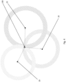
- FIG. 4 there is shown a schematic diagram illustrating how a mower 100 localizes its position through multiple anchors 20 with known positions.
- Each of the anchors 20 and the signaling module 300 of the mower 100 may include a pair of signal transmitter and signal receiver for transmitting an electromagnetic signal to the other anchor 20 or the signaling module 300 and for receiving another electromagnetic signal emitted by or same electromagnetic signal reflected by another anchor 20 or the signaling module 300 respectively.
- each of the anchors 20 will send an electromagnetic signal 22 to the receiver 310 of the mower 100.
- the electromagnetic signal 22 may include ultrawide band radio frequency signal, laser signal, infrared signal etc.
- the electromagnetic signal 22 used in the present invention may be an ultrawide band radio frequency signal in a frequency range of 6 to 8.5 GHz and travelling at speed of light 3 x 10 8 ms -1 .
- the low latency time of ultrawide band radio frequency signal means that the position scan can be repeated up to 100 times per second and thus this is particular suitable for real time positioning applications such as the present mower application.
- the anchors 20 may emit continuous signal strings in a predetermined period. Alternatively, the anchors 20 may only emit a single signal upon triggered by receiving a trigger signal. For instance, the anchors 20 may receive a trigger signal from the mower 100 and in response to the trigger signal, send another signal to the mower 100. Once the signals are received, the processor 400 of the mower 100 will retrieve data relating the time for the signals propagate to the mower 100. With reference to the propagation speed of the signal, the physical distances of the mower 100 with respect to each of the anchors 20 may be determined and in turn, the position of the mower 100 can be calculated by trilateration and/or triangulation.
- the position of the mower 100 may be determined by a time-of-flight method.
- the mower 100 may send a triggering signal 22 to the anchors 20 so as to determine the propagation time of such trigger signal 22.
- the anchors 20 may send a signal 22' back to the mower 100 and obtain another propagation time.
- the mower 100 obtains a triggering signal propagation time period for the triggering signal 22 travelling from the mower 100 to the anchor 20 and a signal propagation time period for the signal 22' travelling from the anchor 20 back to the mower 100.
- the physical distance of the mower 100 with respect to each of the anchors 20 may be determined and thus, the position of the mower 100 may be calculated by trilateration and/or triangulation.
- the position of the mower 100 may be determined by a time-difference-of-arrival method.
- a signal 22 may be sent by the mower 100 to each of the anchors 20 whilst the anchors 20 will not send a signal back to the mower 100.
- the physical distance and therefore the location of the mower 100 may be calculated by multilateration.
- FIG. 5 there is illustrated an example embodiment of determining the location of a mower 100 in a terrain area 10.
- Such operation may be initiated by a user/operator through an application on an electronic device (e.g. a mobile phone) that is wirelessly connected to the mower 100.
- an electronic device e.g. a mobile phone
- the anchors 20a to 20d communicate with each other using, for example wideband, ultrawide band, laser, infrared (represented by the solid line) to establish their respective reference position.
- the mower 100 may send an electromagnetic signal 22 such as an ultrawide band radio frequency signal to any three of the anchors 20a to 20d, for example, the three adjacent anchors 20a to 20c.
- the anchors 20a to 20c receive the signals 22 and then return signals 22' to the mower 100.
- the processor 400 of the mower 100 may calculate the physical distance of the mower 100 with respect to a particular anchor e.g. 20a based on the time required for the signal 22 to travel from the mower 100 to the anchor 20a and to travel back to the mower 100 together with the speed of the signal 22.
- the physical distance D1 between the mower 100 and anchor 20a would be determined by the speed of the signal 22 multiplied by (t2-t1).
- the position of the mower 100 may be calculated by a trilateration and/or triangulation.
- the fourth anchor 20 serves as a back up to verify the position of the mower 100.
- the position of the mower 100 as calculated by the trilateration and/or triangulation may be verified based on the communication between the mower 100 and the additional anchor 20d e.g. the anchor furthest away from the mower 100.
- the use of the fourth anchors 20d may also be useful for measuring the three dimensional position of the mower 100, which includes the relative vertical position of the mower 100 with respect to the reference position i.e. the horizontal level of the anchors 20. This is of particular importance, as the mowing surface may somehow be uneven and the mower 100 may be slightly inclined with respect to the mowing ground.
- the position of the mower 100 may be determined by the communication between the mower 100 and the anchors 20a to 20c based on the method discussed above.
- the mower 100 may send a signal to the additional anchor, for example anchor 20d in this case, which in turn transmits the same signal or another signal back to the mower 100 so as to determine a time that the signal propagates back and forth between the mower 100 and the anchor 20d.
- a physical distance D0 is determined based on the speed of the signal 22 and the propagation time of that signal 22.
- the processor 400 of the mower 100 may compare the estimated distance between the mower 100 and the anchor 20d based on the stored map data of the terrain 10 associated with the communication between the mower 100 and the anchors 20a to 20c with the determined distance D0 between the mower 100 and the anchor 20d for verification. This may be advantageous when the mower 100 is operated in an irregular mowable area which requires enhanced navigation accuracy.
- the initialisation process or routine 408 is a set of procedures which may be performed by a user so as to preconfigure the mower 100 for self-operation in a work area.
- a mowable area 10 as defined by a plurality of anchors 20 positioned at the corners of the area 10.
- a docking station 500 arranged at the bottom of the mowable area for storing and recharging the mower 100.
- the initialization may be implemented by manually teaching the mower 100 the working area/boundary 12 for working.
- a user/operator may stand or sit at a position near the docking station 500, although it would be appreciated that the user/operator stands or sits at any other positions is also possible.
- the user may use a computing device, a virtual controller, or a remote to control the mower 100 to move out from the docking station 500.
- the computing device is a mobile device such as a mobile phone, laptop, smart watch, etc. that is wirelessly connected to the mower 100 and include an application for controlling the mower 100.
- the user may control the mower 100 to move along the perimeters of one or more operation areas 10 so as to teach the mower 100 the operation areas which are needed to be mowed.
- the user may follow the mower 100 during this teaching process so as to monitor the operation path of the mower 100 tightly and avoid crashing the mower 100 into any obstacles therebetween.
- the navigation system 200 may continuously collect navigation information associated with its proximate environment. For instance, the navigation system 200 may active each of odometry module 220 to record the distance of travel as well as the direction of travel, the IMU 236 in measuring the direction of travel, and any other navigation modules or sensors (e.g. GPS 222 or obstacle detection module 224 etc.) which may contribute towards refining the navigation information to achieve a more accurate positioning of the mower.
- the navigation system 200 may active each of odometry module 220 to record the distance of travel as well as the direction of travel, the IMU 236 in measuring the direction of travel, and any other navigation modules or sensors (e.g. GPS 222 or obstacle detection module 224 etc.) which may contribute towards refining the navigation information to achieve a more accurate positioning of the mower.
- the mower 100 is in signal communication with the anchors 20.
- the signal strength of the anchors 20 at various positions on the boundary 12 may be continuously determined by the signalling module 300. Any failure of reception of signal 22 emitted from one or more anchors 20 i.e. signal strength below a predetermined threshold would be recorded in the map data of the terrain 10. The map data would be deployed by the navigation system 200 during normal mowing operation.
- the processor 400 may process the map data to generate a new map or fine tune the preliminary map data associated with the positions of the anchors 20, and in turn map the initial orientation of the mower 100 with the map or the map data.
- the user may use the application included in the mobile device to execute a programme or a procedure stored in the mower for performing the initialization.
- the programme/procedure may begin with controlling the mower 100 to move out from the docking station 500.
- the mower 100 will receive a signal 22 from the anchor 20 so as to determine an initial position of the mower 100 with respect to the anchors 20.
- the mower 100 may move for a short distance with a predetermined angle in a first direction to reach a first position as shown in Figure 7b .
- the mower 100 receives a signal from the anchors 20 which in turn telling the mower 100 how close it is with respect to the anchors 20. After that, the mower 100 returns back to the initial position as shown in Figure 7c . The mower 100 then travels for a short distance with another predetermined angle along another direction that is perpendicular to the direction as shown in Figures 7b and 7c to reach a second position.
- the mower 100 receives another signal 22 from the anchors 20 which tell the mower 100 its distance with respect to the anchors 20 at the current position. The mower 100 then returns back to the initial position. Accordingly, the orientation of the mower 100 may be determined by comparing the position data obtained from the two, first and second positions as shown in Figures 7b and 7e with respect to the anchors 20.
- FIG. 8a and 8b there is shown an example embodiment of how the mower 100 as successfully initialized in Figures 7a to 7e may move around the mowable area to perform the normal mowing operation.
- the mower 100 may start moving at an initial position as described in Figure 7a .
- the mower 100 moves forwards with respect to the docking station 500 until it reaches the boundary 12 as previously determined by the boundary-walking process as shown in Figure 6 .
- the mower 100 rotates by 90 degrees e.g. counter clockwise twice and travels in an opposite, rearward direction for a predetermined distance until the mower 100 reaches the other end 12b of the boundary 12.
- the mower 100 then rotates by 90 degrees clockwise twice and travels in a forward direction again for a predetermined distance until it reaches the first end 12a of the boundary 12 again.
- the mower 100 repeats these steps to cover half of the mowable area 10 until the half of the area 10 is flood filled by the forward traveling path of the mower 100.
- the mower 100 travelled along the travelling path as described above would have only covered half of the working area 10a. In order to flood-fill the rest of the working area 10b, the mower 100 will return to the initial position once it finishes the travelling path as shown in Figure 8a .
- the mower 100 will move in the same manner in the remaining working area 10 but in an opposite direction until the remaining area 10b is covered by the mower 100. Finally, the mower 100 may return to its initial position and dock into the docking area 500 to terminate the mowing operation and/or for battery charging.
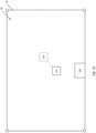
- an example embodiment of an area 10 to be mowed there is illustrated an example embodiment of an area 10 to be mowed.
- the area 10 is of a polygonal shape.
- a house 13 with a barrier connected thereto is provided at the centre portion of the area 10, which in turn dividing the area 10 into two sub-areas 10a and 10b.
- a user may first manually place a plurality of anchors 20 along the perimeter of the sub-areas 10a and 10b.
- the anchors 20 may communicate with each other using different electromagnetic signals 22 such as ultrawide band radio frequency signal, laser signal, infrared signal, or other types of radio-frequency time-of-flight technology, which in turn determining their respective locations.
- the user may perform the aforementioned boundary-walking process to teach the mower 100 the boundaries 12 for operation.
- the user may control the mower 100 to travel along the perimeter of each of the sub-areas 10a and 10b so as to teach the mower 100 the operation areas 10 to be mowed.
- the navigation system 200 of the mower 100 may continuously collect navigation information associated with its proximate environment and such navigation information may be stored in the memory of the mower 100 in the form of a virtual map.
- the map data associated with the sub-areas 10a and 10b may be transmitted to the computing device and graphically presented to the user which may in turn allow the user to pick the specific operation area 10 to be mowed.
- the user may have more than one mower 100 e.g. two mowers 100', 100" for operation.
- Each of the two mowers 100', 100" may be placed in each of the sub-areas 10', 10" respectively.
- the two mowers 100', 100" may be independently in communication with the computing device via wireless connection.
- the user may define the operation boundaries 12', 12" for each of the mowers 100', 100" by performing a boundary-walking process. After that, the mowers 100', 100" determine their positions and orientation as mentioned above and start mowing their respective area 10', 10" simultaneously. In this way, the operation time for mowing would be saved at least by half.
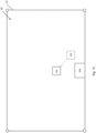
- an area 10 to be mowed there is shown another example embodiment of an area 10 to be mowed.
- the area 10 is also of a polygonal shape.
- a house 13 is provided at the centre top of the mowable area 10.
- an elliptical swimming pool 14 near the bottom right corner of the mowable area 10, which should be a keep out area to be excluded from the mowable area 10.
- the user may divide or partition the global area of operation 10 into different local areas of operation e.g. operation zones 10a, 10b and 10c by ways of deploying a plurality of anchors 20 surrounding the sub-areas 10a, 10b and 10c respectively.
- the operation zones 10a, 10b and 10c are mowed in each operation routine.
- the user may perform a boundary-walking for each of the zones 10a to 10c.
- the user may guide the mower 100 to walk about the boundary 12b of the zone 10b as well as the boundary of the swimming pool 14.
- the map data, inclusive of the boundary associated with the swimming pool 14 i.e. a keep out area, may be stored in the processor 400.
- the user may initially place a mower 100 in zone 10a to perform mowing operation as discuss above. Once the operation in zone 10a is completed, the user may switch the mower 100 to operate in zone 10b, followed by zone 10c.
- the user may deploy sufficient quantity of anchors 20 for covering different zones of area 10, the user may utilise minimum four anchors 20 for mowing all the zones 10a to 10c phase by phase.
- the user may firstly use the plurality of anchors 20 to define a particular zone for mowing operation e.g. zone 10A in Figure 10 .
- a particular zone for mowing operation e.g. zone 10A in Figure 10 .
- the user may remove only some of the anchors 20 from zone 10a and deploy in the rest of the areas 10 not yet mowed so as to define another zones e.g. zones 10b, 10c for operation. These processes may be repeated until the whole area 10 is mowed.
- the anchor 20 is not positioned exactly on the boundary 12.
- the four anchors 20 together usually form a polygonal preliminary boundary with each anchor 20 preferably located at the four corners of the preliminary boundary, the mower 100 will nonetheless perform aforementioned boundary walking process to determine the substantial boundary 12 of the mowing area 10.
- the anchor 20 may not necessarily position exactly at the corners of the polygon e.g. the anchor 20 may be positioned outside or inside the boundary 12. It would be appreciated that the positioning of the anchors 20 merely serves as preliminary boundary and the preliminary boundary will subsequently refined by the user i.e. stretched or reduced during the boundary walking process depending on the position of the obstacles on the terrain 10.
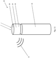
- the anchor 20 comprises an anchor unit 24 supported underneath by a support structure 26.
- the anchor unit 24 is a three-dimensional structure having two, upper and lower planar surfaces located at the top and the bottom of the anchor unit 24. It would be appreciated that the anchor unit 24 may have a cylindrical, cubic, cuboidal shape or a shape of triangular prism, hexagonal prism, etc.
- the anchor unit 24 may comprise a solar panel 28, at least one battery and a signaling module 30.
- the solar panel 28 may be arranged on the upper surface of the anchor unit 20 for absorbing sunlight.
- the solar panel 28 may serve as a power source by converting the solar energy into electrical energy to power the anchor unit 24.
- the solar panel 28 may convert excessive solar energy into electrical energy that can be stored in the battery such that the anchor unit 24 may still operate under cloudy weather or temporarily blocked from sunlight.
- the battery may be of any rechargeable battery, examples include but not limiting to nickel-cadmium, nickel-metal hydride, lithium-ion, lithium-ion polymer batteries, etc.
- the anchor unit 24 When anchor 20 is operated under an environment that the solar panel is not able to power the anchor unit 24, the anchor unit 24 may be powered solely by the battery or in combination with the solar panel.
- the combination of solar panel and battery as the power source may be advantageous that it may provide a more environmental-friendly mowing operation.
- the signal module 30 of the anchor unit 24 may include a signal receiver and a signal transmitter which in turn allow the anchor 20 to communicate with other anchors 20 as well as the signalling module 300 of the mower 100. In this way, the position of the anchor 20 and the mower 100 may be determined based on the signals transmitted between the anchors 20 and between the anchors 20 and the mower 100.
- the support structure 26 may be a rod-shaped or a cylindrical shaped structure whilst it would be appreciated that other structures with elongated shape may also be possible.
- the support structure 26 provides a surface to allow the anchor unit 24 to be releasably attached onto the support structure 26. In this way, the anchor unit 24 is positioned at a higher position to avoid most of the obstacles and in turn, allows the signal 22 to be emitted from the anchor unit 24 to cover a boarder range under a desirable line of sight.
- the releasable arrangement between the anchor unit 24 and the support structure 26 may provide flexibility to the user for mowing operation area 10 with different zones e.g. zones 10a, 10b and 10c as mentioned in the previous scenarios shown in Figure 10 .
- the mower 100 may use a virtual boundary created by the user during the boundary-walking process and mapping of the garden 10.
- the position accuracy of the mower 100 has a plus/minus tolerance based on the precision of the navigation sensors e.g. the signalling module 300.
- the signalling module 300 may give accuracy up to 10 to 20 cm and thus the mower 100 may comply with the safety regulation which allows only a maximum mower body length of 0.5 meters extending from the boundary 12.
- a user may use a set of autonomous tool 100 including but not limited to multiple anchors 20 and a mower 100 in a garden, backyard 10 or in other similar context decided by a skilled addressee for the specific usage.
- the user in order to interact with any component of or the entire navigation system 200, inclusive of but not limited to the deployed anchors 20 and the autonomous tool 100, the user is required to download a mobile application onto a mobile device.
- the mobile devices could be smartphones, computers, computer tablets etc. Through these mobile devices, the user would then be able to communicate and remotely control the activities of the anchors 20 and the autonomous tool 100.
- the means to control the aforementioned system 200 and tool 100 does not limit to mobile apps. The user may also control through other means such as remote control came along with the system 200 and tool 100.
- anchors 20 may be operated in different modes serving for different purposes.
- the main feature of the anchors 20 i.e. the first mode is referred to as “mowing mode” whilst the side feature i.e. the second mode is referred to as “internet of things (IOT) mode”.
- IOT internet of things
- the anchors 20 would assist the mower 100 in mowing a garden or yard 10 as they would define the boundary 12 for the mower 100 to operate within.
- the anchors 20 would operate as a channel to facilitate the communication between an object (e.g. lamp, surveillance camera etc.) on which the anchor 20 is embedded and the mobile device with the "app" installed.
- object e.g. lamp, surveillance camera etc.
- Such mode provides user with remote controllability over the embedded object at any time provided there is wireless connectivity.
- a user may firstly access to a website or another third party's "apps" which hosts the download link of the "apps” to control the autonomous tool 100 and anchors 20. Then, the user may download the "apps" to the intended mobile device(s).
- the user may tap open the "apps” and register a personal account. Subsequently, the system may request the user to link the "app” with purchased anchors 20 and the mower 100. This may be done by scanning the "QR code” or other similar unique signature labelled on the anchors 20 and the mower 100 with the scanner function of the "apps".
- the user may be requested to type the unique identification code labelled on those devices in the "apps".
- the anchors 20, the mower 100, and the mobile device with the "app" installed thereon would be linked and communicable with each other.
- the user could wirelessly control the paired anchors 20 and the mower 100 with the mobile device.
- anchors 20 Examples of a deployment of anchors 20 may be found in places where mowing is required. This may include but not limited to backyard, front yard, gardens in park 10 or other facilities. In this context, mower 100 may operate within the boundaries 12 defined by the anchors 20.
- these anchors 20 may also be used indoor such as but not limited to office, home and shopping malls. Users may attach an anchor 20 to a compatible device such as but not limited to light, curtain, surveillance camera etc. and control the activities thereof. Thus, it may operate as a boundary-defining object or a device to facilitate internet of things.
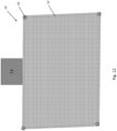
- FIG. 12 there is shown a mansion wherein the house 13 itself is located at a side of a quadrilateral shaped yard 10.
- the user may deploy an anchor 20 at each corner, in total there may be at least four anchors 20 deployed. The user has to make sure placing the anchor 20 on line-of-sight and that there is no obstacle blocking the line-of-sight between all the anchors 20.
- the user For the first time of use, having had the mobile device paired up with a mower 100 and anchors 20, the user is required to control, through the mobile apps, the mower 100 to perform an aforementioned boundary-walking process.
- FIG. 13 there is shown a layout of a mansion similar to that displayed in Figure 12 .
- the user Before the start of boundary walking, the user is required to lay the mower 100 at any point on either one of the boundaries 12. The user is also required to tap open the "apps" installed in the mobile device and select the relevant function on the "apps". Then, the user could begin the boundary walking phase by controlling the mower 100 to walk along all four boundaries 12 by the mobile device or any other remote controller as demonstrated by the arrow sign in the Figure.
- the mobile device may be communicable with the mower 100 through the user of Wi-fi, Bluetooth, or other similar radio frequency identification methods. The entire process of boundary walking would end when the mower 100 walks back to the point where it began the process of boundary walking.
- the anchors 20 may alert the user through the mobile app upon should the mower 100 mistakenly trespass through the fences. Such alert may be communicated with the use of any radio frequencies identification method such as but not limited to Wi-fi and Bluetooth.
- a garden or yard 110 may contain more than four corners.
- FIG 16 there is shown a house 13 and a pavement 15 stretched from the house 13 to an entrance of the mansion. In this case, surrounding the house 13 and the pavement 15, there are in total twelves corners in the mansion. In this scenario, the user may opt to purchase more anchors 20 and station them at every corner in the mansion.
- a user may opt to divide the entire yard 10 into multiple rectangular sections as many as the user may wish. The user may then select to operate on either one of the section by setting up the four anchors 20, one at each corner. In this embodiment and for the first time of use, the user will have to set up four anchors 20 at each corner at zone 10a as illustrated. Then, the user has to perform the boundary walking within zone 10a before the mower 100 can operate itself in zone 10a. This process repeats for other zones 10b, 10c etc.
- the mobile app may prompt the user to save the generated map in some memory space.
- the memory space may be but not limited to any electronic devices, mower 100 or anchors 20 through any radio frequency identification techniques.
- the user may remove the anchors 20 previously deployed at zone 10a and reuse them in zone 10b as demonstrated in Figure 18 . This process may repeat for the rest of the zones 10c etc. until all zones are completed with the boundary walking phase.
- a user may start the mowing phase. It is necessary to take note that the mowing phase may be carried out as long as any one of the zones e.g. 10a is "boundary-walked” rather than having all the zones 10a, 10b, 10c being “boundary-walked”. Again, the user is required to place the anchors 20 at the recorded position during the boundary walking phase although it may not require the same anchor 20 at the exactly same position. In other words, it may be sufficient to have a different anchor 20 at the exactly same position.
- the user may have to firstly make sure the mower 100 is connected to the anchors 20. Then, the user may tap open the "apps" and select a function that will wirelessly, through Wi-fi, Bluetooth or other radio frequency identification methods, instruct the mower 100 to start mowing within the zone 10. When the zone 10 is mowed, the mower 100 may return to its dock 500 and await for the next instruction from the user. Should there be more zones to be mowed, the user may firstly remove the anchors 20 and place it to corners at other zones, then the user may tap on the apps and instruct the mower 100 to mow that particular area 10 in accordance with the zone map generated in the "boundary walking" phase.
- an anchor 20 may also be used as an internet of things on variety of objects such that a user may control the activity of the object on which the anchor 20 is embedded remotely.
- Those objects may be any everyday objects such as but not limited to lamp, curtain, coffee machine, air conditioner, fan, surveillance camera and so on and so forth.
- the user may have to manually disengage the anchor 20 from the object on which it was previously embedded on before the user can fasten it on a new object by some locking mechanism.
- the anchor 20 may wirelessly (by means of some radio frequency identification techniques such as but not limited to Wi-fi and Bluetooth) or by wire pair and communicate with the embedded object. Upon successful pairing, the anchor 20 may send a notification and prompt for further action on the "apps". The user may then tap open the notification may wirelessly control the activities of the embedded object. For example, the user may wirelessly turn on or off the lamp or the user may match the closed-circuit television on the "apps" should the anchor 20 is embedded on these objects.
- some radio frequency identification techniques such as but not limited to Wi-fi and Bluetooth
- the embodiments described with reference to the Figures can be implemented as an application programming interface (API) or as a series of libraries for use by a developer or can be included within another software application, such as a terminal or personal computer operating system or a portable computing device operating system.
- API application programming interface
- program modules include routines, programs, objects, components and data files assisting in the performance of particular functions, the skilled person will understand that the functionality of the software application may be distributed across a number of routines, objects or components to achieve the same functionality desired herein.
- the mower 100 may not localise its position by way of aforementioned trilateration and/or triangulation as described in Figures 4 to 5 which requires receiving of signals from at least three signal source, the current position, the orientation and the traveling direction of the mower 100 may be determined based on the signals 22 emitted by at least two anchors 20.
- FIG. 19 there is shown a terrain 10 to be mowed by the mower 100 and surrounded by four anchors 20a, 20b, 20c and 20d respectively.
- the mower 100 is at a position where the signal 22 emitted from anchors 20c and 20d are substantially blocked by a house 13.
- the mower 100 may still continue the mowing operation and travels along the travelling path e.g. defined by aforementioned flood-fill process based on the reference position of anchors 20a and 20b.
- the current position of the mower 100 may be determined by aforementioned trilateration and/or triangulation again.
- any appropriate computing system architecture may be utilised. This will include stand alone computers, network computers and dedicated hardware devices. Where the terms “computing system” and “computing device” are used, these terms are intended to cover any appropriate arrangement of computer hardware capable of implementing the function described.
Description
- The present invention relates to a navigation system and a method for controlling a device, and particularly, although not exclusively, to a navigation system for use in an autonomous tool and a method for controlling an autonomous tool.
- The maintenance of lawns requires a significant amount of manual labour including constant watering, fertilizing and mowing of the lawn to maintain a strong grass coverage. Although watering and fertilizing can sometimes be handled with minimal effort by use of a sprinkler or irrigation system, the mowing process is one process that demands a significant amount of physical effort from gardeners.
- Designers and manufacturers of lawn mowers have attempted to manufacture autonomous lawn mowers for some time to replace the traditional push pull mowers. However, the unpredictability of a landscape together with the cost of creating an accurate and usable product has meant many autonomous lawn mowers simply do not perform at an adequate level of performance.
- The
US 2016/165795 A1 discloses a method of mapping an area to be mowed with an autonomous mowing robot, wherein mapping data are received from the mowing robot, specifying an area to be mowed as well as a plurality of locations of beacons and geographic coordinates for reference points within the area. TheUS 2015/271991 A1 refers to a robot lawn mower including a drive system, a localization system, a teach monitor and a controller, wherein a data-processing device of the controller executes a teach routine for tracing a perimeter around the lawn and storing global positions determined by the localizing system. TheUS 2012/089323 A1 describes an optical system mounted to a moving object for navigation in an array of beacons having at least one optical emitter emitting an optical signal. TheWO 2017/123137 A1 relates to a method for navigating a robotic tool within an area, the robotic tool receives signals from a beacon and determines a distance to the beacon, wherein accelerometers or odometers are further used to determine the position of the robotic tool within the operation area. The document XP56013766 relates to an autonomous urban snow removal with a localization and navigation system using Ultra-Wideband beacons and GPS data as well as wheel odometer and inertial navigation systems, wherein active beacons provide an external absolute frame for the operation area. - The present shortcomings are in part due to the fact that gardens come in many different varieties and shapes, with different elevations and profiles. Thus the autonomous mowers have had significant trouble in navigating these different types of terrain. In turn, many push mowers are still preferred by users as their performance and control can still be manually controlled to overcome problems associated with different landscape profiles.
- In accordance with a first aspect of the present invention, there is provided a navigation system as defined by claim 9 arranged for use with the method for controlling an autonomous tool according to
claims 1 to 8 comprising: a plurality of anchors disposed separately on a terrain each arranged to emit an electromagnetic signal; a signaling module including a signal receiver arranged to receive the electromagnetic signal, wherein the signaling module is connected to the autonomous tool arranged to move on the terrain; and a processor arranged to process the electromagnetic signal received by the signal receiver so as to determine a physical distance between the signaling module and each of the plurality of anchors; wherein the processor is further arranged to determine a current position of the signaling module with respect to a reference position on the terrain based on the determined physical distances and map data of the terrain associated with a position of each of the plurality of anchors. - In an embodiment of the first aspect, the processor is further arranged to determine the current position of the signaling module based on the determined physical distances and the map data of the terrain associated with the position of at least three of the plurality of anchors.
- In an embodiment of the first aspect, the processor is further arranged to verify the current position of the signaling module based on the determined physical distances and the map data of the terrain associated with the position of an additional anchor other than the at least three of the plurality of anchors.
- In an embodiment of the first aspect, the processor is arranged to determine the physical distance between the signaling module and each of the plurality of anchors based on a signal propagation period of the electromagnetic signal emitted from each of the plurality of anchors reaching the signaling module.
- In an embodiment of the first aspect, the processor is further arranged to determine the physical distance between the signaling module and each of the plurality of anchors based on a signal propagation speed of the electromagnetic signal on the terrain.
- In an embodiment of the first aspect, the physical distance is determined based on a time-of-flight calculation method.
- In an embodiment of the first aspect, the reference position includes a docking position of the autonomous tool.
- In an embodiment of the first aspect, the reference position includes the position of one of the plurality of the anchors.
- In an embodiment of the first aspect, the electromagnetic signal includes a radio frequency signal.
- In an embodiment of the first aspect, the electromagnetic signal includes an ultrawide band radio frequency signal.
- In an embodiment of the first aspect, the electromagnetic signal includes an infrared signal.
- In an embodiment of the first aspect, the electromagnetic signal includes a laser signal.
- In an embodiment of the first aspect, the navigation system further comprises at least one sensor arranged to provide supplementary information associated with a navigation of the autonomous tool to the processor.
- In an embodiment of the first aspect, the at least one sensor includes at least one of an IMU, an odometry sensor and a GPS sensor.
- In an embodiment of the first aspect, the plurality of anchors are positioned at a plurality of corners of a polygonal area on the terrain.
- In an embodiment of the first aspect, the autonomous tool is arranged to operate within the polygonal area bound by the plurality of anchors.
- In an embodiment of the first aspect, at least one of the plurality of anchors is positioned away from a predetermined boundary of a target area of operation on the terrain.
- In an embodiment of the first aspect, the autonomous tool includes an outdoor tool or an indoor tool.
- In an embodiment of the first aspect, the outdoor tool includes an autonomous lawn mower, a snow thrower or a pressure washer.
- In an embodiment of the first aspect, the indoor tool includes a vacuum cleaner.
- In accordance with a second aspect of the present invention, there is provided a method for controlling an autonomous tool as defined by
claim 1, comprising the steps of: receiving, at a current position of the autonomous tool, an electromagnetic signal emitted from each of a plurality of signal sources disposed separately on a terrain; processing the received electromagnetic signals thereby determining a physical distance between the autonomous tool and each of the plurality of signal sources; and determining the current position of the autonomous tool with respect to a reference position on the terrain based on the determined physical distances and map data of the terrain associated with a position of each of the plurality of signal sources. - The current position of the autonomous tool with respect to a reference position on the terrain is determined based on the determined physical distances and the map data of the terrain associated with the position of at least three of the plurality of signal sources.
- In an embodiment of the second aspect, the physical distance between the signaling module and each of the plurality of signal sources is determined further based on a signal propagation speed of the electromagnetic signal on the terrain.
- In an embodiment of the second aspect, the method further comprises the steps of transmitting, from the autonomous tool; a triggering signal to each of the plurality of signal sources; wherein the plurality of signal sources is arranged to transmit the electromagnetic signal upon receiving the triggering signal.
- In an embodiment of the second aspect, the method further comprises the step of determining the physical distance between the autonomous tool and each of the plurality of signal sources based on a signal propagation period of the triggering signal emitted from the autonomous tool reaching each of the plurality of signal sources and the electromagnetic signal emitted from each of the plurality of signal sources reaching the autonomous tool respectively.
- In an embodiment of the second aspect, the physical distance is determined based on a time-of-flight calculation method.
- In an embodiment of the second aspect, the reference position includes a docking position of the autonomous tool.
- In an embodiment of the second aspect, the reference position includes the position of an anchor, wherein the anchor is the signal source arranged to emit the electromagnetic signal.
- In an embodiment of the second aspect, the method further comprises the step of processing supplementary information associated with a navigation of the autonomous tool, wherein the supplementary information is provided by at least one sensor.
- In an embodiment of the second aspect, the at least one sensor includes at least one of an IMU, an odometry sensor and a GPS sensor.
- In an embodiment of the second aspect, the method further comprises the step of determining a travelling path starting from the current position of the autonomous tool, wherein the travelling path substantially flood fills a target area of operation bound by a predetermined boundary.
- In an embodiment of the second aspect, the travelling path is determined based on an A* pathfinding process.
- In an embodiment of the second aspect, the plurality of anchors are positioned at a plurality of corners of a polygonal area defining the target area of operation on the terrain.
- In an embodiment of the second aspect, the method further comprises the step of defining at least one keep out area to be excluded from the target area.
- In an embodiment of the second aspect, the method further comprises the step of creating and storing map data of the terrain associated with positions of the anchors, the target area of operation and the at least one keep out area.
- In an embodiment of the second aspect, the map data is created upon running a boundary-walking routine on the autonomous tool.
- In an embodiment of the second aspect, at least one of the plurality of anchors is positioned away from the predetermined boundary.
- In an embodiment of the second aspect, the map data is created by an application executed on a computing device.
- In an embodiment of the second aspect, the method further comprises the step of partitioning a global area of operation into a plurality of local areas of operation based on a plurality of boundaries defined by the plurality of anchors disposed separately on the terrain.
- In an embodiment of the second aspect, the autonomous tool is controlled to operate on one of plurality of local areas of operation in each operation routine.
- In an embodiment of the second aspect, the method further comprises the step of initializing an operation of the autonomous tool prior to the step of determining a travelling path starting from the current position of the autonomous tool.
- In an embodiment of the second aspect, the step of initializing an operation of the autonomous tool comprises the step of obtaining an orientation of the autonomous tool by: determining an initial position of the autonomous tool with respect to the reference position on the terrain; rotating the autonomous tool from a first direction to a second direction; and travelling the autonomous tool with a predetermined distance along the second direction; and determining the orientation of the autonomous tool positioned at the second direction based on the determination of the initial position and the current position with respect to the reference position.
- The method further comprises the step of determining the current position of the autonomous tool based on a failure of reception of electromagnetic signal emitted from at least one of the plurality of signal sources during an operation of the autonomous tool.
- In an embodiment of the second aspect, the method further comprises the step of recording the failure of reception of the electromagnetic signals associated with a predetermined position in the map data of the terrain.
- In an embodiment of the second aspect, the method further comprises the step of continuing the operation of the autonomous tool in response to the failure of reception of the electromagnetic signal.
- In an embodiment of the second aspect, the method further comprises the step of resuming the determination of the current position of the autonomous tool based on trilateration and/or triangulation upon successfully receiving the electromagnetic signal emitted from at least three of the plurality of signal sources.
- In an embodiment of the second aspect, the autonomous tool includes an outdoor tool or an indoor tool.
- In an embodiment of the second aspect, the outdoor tool includes an autonomous lawn mower, a snow thrower or a pressure washer.
- In an embodiment of the second aspect, the indoor tool includes a vacuum cleaner.
- Embodiments of the present invention will now be described, by way of example, with reference to the accompanying drawings in which:
-
Figure 1 is an illustration of an autonomous lawn mower in accordance with one embodiment of the present invention; -
Figure 2 is a block diagram illustrating an example of various control systems and modules of the autonomous lawn mower ofFigure 1 ; -
Figure 3 is a flow chart illustrating the operation of the autonomous lawn mower ofFigure 1 ; -
Figure 4 is a schematic diagram showing the triangulation of an object at an unknown position; -
Figure 5 is a schematic diagram showing the triangulation of the mower within a boundary area; -
Figure 6 is a schematic diagram showing the boundary- walking of the autonomous lawn mower about the boundary area; -
Figure 7a is a schematic diagram showing the initial movement of the autonomous lawn mower from its origin; -
Figure 7b is a schematic diagram showing the initialization of the autonomous lawn mower; -
Figure 7c is a schematic diagram showing the initialization of the autonomous lawn mower; -
Figure 7d is a schematic diagram showing the initialization of the autonomous lawn mower; -
Figure 7e is a schematic diagram showing the initialization of the autonomous lawn mower; -
Figure 8a is a schematic diagram showing the mowing path of the autonomous lawn mower; -
Figure 8b is a schematic diagram showing the mowing path of the autonomous lawn mower; -
Figure 9 is a schematic diagram showing a first mowing scenario; -
Figure 10 is a schematic diagram showing a second mowing scenario; -
Figure 11 is an illustration of an anchor in accordance with one embodiment of the present invention; -
Figure 12 is a schematic diagram showing a third mowing scenario; -
Figure 13 is a schematic diagram showing a third mowing scenario; -
Figure 14 is a schematic diagram showing a fourth mowing scenario; -
Figure 15 is a diagram illustrating a typical garden with numerous obstacles; -
Figure 16 is a schematic diagram showing a fifth mowing scenario; -
Figure 17 is a schematic diagram showing a sixth mowering scenario; -
Figure 18 is a schematic diagram showing a sixth mowering scenario; and -
Figure 19 is a schematic diagram showing an alternative mowing scenario, in which the mower is located with reference to only two of the anchors. - With reference to
Figures 1 to 19 , there is provided an illustration of anavigation system 200 for use in anautonomous tool 100, comprising: a plurality ofanchors 20 disposed separately on aterrain 10 each arranged to emit anelectromagnetic signal 22; asignaling module 300 including a signal receiver 310 arranged to receive theelectromagnetic signal 22, wherein thesignaling module 300 is connected to theautonomous tool 100 arranged to move on theterrain 10; and aprocessor 400 arranged to process theelectromagnetic signal 22 received by the signal receiver 310 so as to determine a physical distance between thesignaling module 300 and each of the plurality ofanchors 20; wherein theprocessor 400 is further arranged to determine a current position of thesignaling module 300 with respect to a reference position on theterrain 10 based on the determined physical distances and map data of theterrain 10 associated with a position of each of the plurality ofanchors 20. - In this example, the
autonomous tool 100 may be incorporated as an outdoor tool such as anautonomous lawn mower 100 arranged to operate on a lawn or grass grown surface so as to cut the grass. This action is commonly known as "mow the lawn" and is often undertaken by gardeners and landscape workers to maintain a lawn surface. The termautonomous lawn mower 100 may also include any type of grass cutting device or lawn mower which can operate autonomously, that is, with minimum user intervention. It is expected that user intervention at some point is required to set up or initialize the mower or to calibrate the mower with specific commands, but once these procedures have been undertaken, themower 100 is largely adapted to operate on its own until further commands are required or if servicing, calibration or error correction is required. Accordingly,autonomous lawn mowers 100 may also be known as automatic lawn mowers, self-driven lawn mowers, robotic lawn mowers or the like. - In this embodiment as shown in
Figure 1 , theautonomous lawn mower 100, or referred to as the lawn mower or mower, includes a frame orhousing 102 which supports the operating components of themower 100. These operating components may include, without limitation at least one motor, such as an electric motor, which is arranged to drive the blades of the mower so as to cut the grass of a lawn to which the mower is mowing. The at least one motor may also be used to drive the mower itself via the means of transmission systems, such as gearing mechanisms or gearboxes which transmit a driving force to itswheel arrangements 104, although preferably, as is the case of this embodiment, separate motors are used to drive the mower along its operating surface with eachrear wheel 104R having its own individual motor and gearbox. This is advantageous in that manoeuvring the mower may be implemented by simple control of each of these motors. It is important to note that the term wheel arrangements may also include driving arrangements that are formed from various different types and combination of wheels, including tracks (such as in tank tracks), chains, belts (such as in snow belts) or other forms of driving arrangements. - In other examples, the term autonomous tool may include other outdoor tools such as snow throwers, electric or gas blowers, landscaping tools, multi-function outdoor equipments, portable generators, pressure washers, pumps, soil care, watering e.g. hoses, fertilisers, or soil investigating tools. In some other examples, the term autonomous tool may also include any indoor tools such as vacuum cleaners, fans, air filters, or portable heaters.
- Preferably, as shown in the embodiment of
Figures 1 to 2 , themower 100 includes anavigation system 200 which operates to locate and navigate themower 100 around a workingarea 10 so that themower 100 can cut the grass of a workingarea 10. Thenavigation system 200 may include a number of specific navigation modules each arranged to provide individual navigation information obtained for themower 100. In turn, the navigation information obtained or determined by each of these navigation modules are then returned to thenavigation system 200 for transmission to acontroller 400. Upon processing of the navigation information by thecontroller 400, thecontroller 400 may then generate commands which are used to control the movement and operation of themower 100 within a work oroperation area 10. - These navigation modules may include at least the follow:
- A
signaling module 300 having a signal receiver 310 arranged to communicate with a plurality ofanchors 20 positioned separately on aterrain 10 each arranged to emit anelectromagnetic signal 22 so as to assist in the determination of the location of themower 100 with respect to a reference point; - An
odometry module 220 arranged to determine the distance travelled by thewheels 104 so as to assist in the determination of the location of themower 100 from a starting point; - An inertial measurement unit (IMU)
module 226 arranged to measure the force of movement of themower 100 by detecting and recording various forces which are subjected on themower 100, including the direction of movement, force of movement, magnetic bearing of movement, acceleration and gyroscopic movements. In some example implementations, more than oneIMUs 226 may be used to improve accuracy, sinceadditional IMUs 226 will assist in eliminating errors over time - Other additional navigation modules (not shown) may also be implemented to communicate with the navigation system so as to provide further input to the navigation system to adjust and control the mower, for example,
GPS sensor 222 which can be used to obtain a GPS coordinate of themower 100 andobstacle detection module 224 which can be used to prevent themower 100 from crashing into an obstacle. - These navigation modules are each arranged to obtain, detect and determine a set of navigation related information, which are in turn arranged to be processed by a
processor 400 on the controller to devise suitable commands to operate themower 100. As it will be explained below with reference toFigures 7a to 8b , in one example, theautonomous lawn mower 100 will operate by starting from adocking station 500 which will form a start and return point for themower 100. Themower 100, when departing thedocking station 500 may then use thenavigation system 200 to assist with navigating themower 100 around a work oroperation area 10 by cutting the lawn in theoperating area 10, and then proceeding to navigate its way back to thedocking station 500. - With reference to
Figure 2 , there is provided a block diagram of theautonomous lawn mower 100 which illustrates the essential components of theautonomous lawn mower 100. In this embodiment, themower 100 includes a controller/processor 400 which may be implemented as a computing device, or as one or more control boards, with each having one ormore processors 400 arranged to receive and analyse the information received and to provide instructions to themower 100 in order to operate themower 100. Preferably, the controller/processor 400 is implemented with a main printed circuit board assembly (PCBA) arranged to have two processors on the PCBA and to operate together with an additional computing module. Several of the sensor PCBAs may also have their own individual microcontroller units (MCUs). - The controller/
processors 400 is arranged to receive navigation information from thenavigation system 200 of themower 100 and in turn, upon the receipt of this navigation information, will process the navigation information with existing information already accessible by thecontroller 400 such as thecontrol algorithm 406 or predefined map of the operating area to generate various commands to each of the mower operating components, including thedrive motors 210 arranged to drive the mower and/or the blade motors 212 which operates the blades. - The
navigation system 200 includes thesignaling module 300, theodometry module 220 which includeswheel sensors 232 to detect the rotational displacement of the wheels of themower 100, and theIMU unit 226. - The
signalling module 300 includes a signal receiver 310 for receiving a signal embedded with the relative position of themower 100 with respect to a reference position from a signal source. To facilitate the receipt of signal, thesignalling module 300 also includes asignal transmitter 320 for emitting a trigger signal to request or trigger the transit of such signal from the signal source to thesignalling module 300. - Preferably, the signal source may share a similar or identical construction with the
signalling module 300 and may be incorporated as ananchor 20 which receives a trigger signal from thesignal transmitter 320 of thesignalling module 300 and in turn, emits a signal associated with the relative position of themower 100 with respect to a reference position to the signal receiver 310 of thesignalling module 300. - Although the
signalling module 300 may be accurate in determining the position of themower 100,IMU 226,odometry sensor 232 andoptionally GPS sensor 222 serve as additional sensors for providing supplementary information associated with themower 100 to improve the accuracy of the positioning. - The
odometry module 220 may be implemented into each of two motors arranged to drive therear wheels 104R of themower 100. For instance, theodometry module 220 is provided one or more absolute encoders or encoder sensors to measure the number of rotations of thewheels 104R to which theodometry module 220 is implemented to operate with. In turn, the number of rotations, when coupled with the circumference of thewheel 104R will provide an estimation as to the distance travelled by themower 100 on a work surface (taking into account any gear ratios, if applicable). As themower 100 may also turn along its work surface by allowing its opposing wheels to spin in opposite directions, such movements and rotation can also be detected and measured so as to determine the direction and rate of turn of themower 100 along a work surface. - Once the number of rotations is determined, the number of rotations of each
wheel 104R, including its direction and whether the wheels 10R are undergoing a turning direction, will then be transmitted to thecontroller 400 for processing. In turn, thecontroller 400 can then process this result with other information from thenavigation system 200 to ascertain the location of themower 100. - On the other hand, the
IMU module 226 may be implemented to measure the force of movement of the mower by detecting and recording various forces which are subjected to themower 100. For instance, theIMU 226 detects and records various forces which are subjected on themower 100, including the direction of movement, force of movement, magnetic bearing of movement, acceleration and gyroscopic movements. Preferably, theIMU 226 functions by using at least one accelerometer to detect the rate of acceleration or deceleration of the mower, at least one gyroscope to detect the gyroscopic movements of the mower and a magnetometer to detect the magnetic bearing of movement of the mower. - The
controller 400 may receive the navigation information detected by theIMU module 226. Following processing by aprocessor 400, suitable commands to operate themower 100 can be developed based on the navigation information supplied by theIMU module 226. - Each of these modules are arranged to provide a specific function and return individual navigation information either detected, calculated, gathered or surveyed, as in the case of the
signalling module 300 which is arranged to receiveelectromagnetic signal 22 emitted by one or more anchors 20. - As illustrated in this embodiment, the
controller 400 is also arranged to control themower drive motors 210 to drive themower 100 along a work surface within a work area. Preferably, as is the case in this embodiment, themower 100 is driven by having amotor 210 placed adjacent to each of therear wheels 104R with eachmotor 210 being arranged to drive eachrear wheel 104R. - In turn, the
controller 400 can direct electric current from a power source, such as abattery 214, to themotors 210 so as to perform a controlled operation of one or bothmotors 210. This can allow for forward, reverse and turning actions of themower 100 by turning one or more wheels at different speeds or directions. - The
controller 400 can also command the blade motor 212 to operate so as to operate the blades to cut the grass of a work surface. To perform these functions, thecontroller 400 will execute a control routine or process 206 which determines the conditions for and when themower 100 is to be operated. These commands at least include instructions to command the direction of travel of themower 100 and the operation of the blades 212. - Other commands are also possible, including the command of the
mower 100 to travel to a particular location within a work area, or to return to a specific location, such as adocking station 500 as well as specific commands such as the operating speed of the blade motor 212 or the height of the blade 212 so as to determine the level of grass that is cut. - As it will be explained below with reference to
Figure 6 , thecontroller 400 may also be pre-programmed with aninitialization routine 408 wherein the mower's working area andwork surfaces 10 are initially identified. These process may assist in identify the boundaries of a working area and the categorization that certain surfaces within theboundaries 12 should be avoided (no travel zones) or should not have the blade motor activated 212. Once these workingareas 10 are identified, themower 100 can then be controlled by thecontroller 400 to navigate to a starting point from thedocking station 500, wherein themower 100 can proceed to cut the grass from the starting point as stipulated by thecontrol algorithm 406. - For instance, the
control algorithm 406 may include a specific cutting program, which mows thelawn 10 along a travelling path e.g. along a longitudinal axis and then work each longitudinal axis in a latitudinal form within the working area defined so as to cut the grass in the workingarea 10 which is bounded by apredetermined boundary 12. More specifically, the workingarea 10 may be covered by themower 100 via a travelling path determined based on an A* pathfinding process or a flood-fill cutting algorithm as will be explained below with reference toFigures 8a to 8b . Other cutting programs are also possible and can be chosen base on the shape and profile of the workingarea 10 of the desired operation of a user. - Preferably, as the
controller 400 will communicate with each of the navigation modules of thenavigation system 200, thecontroller 400 may, during initialisation and general operation, receive a large amount of different navigation information from each of these navigation modules. In order to process this navigation information so as to determine operation commands for themower 100, thecontroller 400 may first apply a filter or an averaging function to all of navigation information received from thenavigation system 200. Such a filtering function may allow thecontroller 400 to ignore or minimize any weighting placed on navigation information obtained from a first navigation module that appears to be incorrect when compared with navigation information obtained from other navigation modules. One or more filters can be applied to assist with identifying a "best fit" trend for all navigation information received by thecontroller 400 and in turn, allowing anomalies, deviations or inconsistencies, which may be far away from the average or best fit trend, to be ignored or further investigated. - As an example, the
controller 400 may receive navigation information from thesignaling module 300 and theodometry module 220. During processing, theodometry module 220 may have tracked that themower 100 has travelled to a particular position with respect to a reference position on theterrain 10. However, according to the navigation information obtained by thesignaling module 300 andIMU 226, the location of themower 100 may be at a distance substantially far away from the co-ordinates obtained from theodometry module 220. In these instances, when the filtering function is applied to all navigation information of thesignaling module 300 and theodometry module 220, the "best fit" or "average" may in turn indicate that the co-ordinates of theodometry module 220 is an anomaly, as it is completely inconsistent with the other navigation modules. Accordingly, thecontroller 400 may then proceed to ignore this anomaly in generating commands to themower 100. - It is also expected that the
controller 400 may also apply a similar filtering function to all data obtained from thenavigation system 200 and other sensors such asGPS sensors 222,obstacle detection module 224 etc. Such filter may be advantageous for reducing/eliminating bad data points from each source and to assist in determining which sources of navigation/localization data are most reliable and use select these sources instead. - With reference to
Figure 3 , there is shown a flow chart illustrating an example embodiment of aprocess flow 3000 of operating theautonomous lawn mower 100. The operation may begin withstep 3001 of placement of the plurality ofanchors 20 at a predetermined position within anoutdoor garden 10. - A user/operator may place the plurality of
anchors 20 to define aphysical area 10 for operating themower 100. In one example, the user may simply place theanchors 20 along the perimeter of theterrain 10. In other words, theanchors 20 may be placed to form a polygonal area for mowing operation. Preferably, the user/operator may also placeadditional anchors 20 to surround any particular area within theterrain area 10 according to specific needs e.g. accommodating signal blind spot within theterrain 10. - In one example, the
anchors 20 may be directly inserted onto theterrain area 10 and then being activated by the user through a switch on theanchors 20 or through a remote computing device such as a mobile phone that is wirelessly connected to theanchors 20. In another example, theanchors 20 may be inserted to a plurality of sleeves that are predefined on theterrain 10. In this way, theanchors 20 are in electrical communication with a power supply e.g. a battery positioned at the sleeves. - Upon the
anchors 20 are positioned at the desirable positions and switched on, theanchors 20 may communicate with each other to indicate their respective position within theterrain area 10 by sendingelectromagnetic signals 22 to or receivingelectromagnetic signals 22 from each other atstep 3002.Such signals 22 may also be transmitted from theanchors 20 to the computing device such that the individual position of theanchors 20 may be visually or graphically displayed on the remote computing device. - The position of the
anchors 20 may together ideally define a preliminary boundary. However, there may be some obstacles located in between the area or theterrain 10 may not be exactly in regular shape. To fine-tune the preliminary boundary, the user may collect map data of theterrain 10 by moving themower 100 around theterrain 10 to generate map data atstep 3003 for determine themowing area 10. By doing so, themower 100 can then be taught by the user as to the location and definition of the workingarea 10 as well as any travel paths which are required to cover different portions of the workingarea 10. - In one example, the user may firstly manual operate the
mower 100 along the perimeters of one ormore operation areas 10 so as to teach themower 100 theoperation areas 10 which are needed to be mowed by themower 100. This may sometimes be referred to as the "boundary-walking mode", representative of a user in "walking" the mower along theboundary 12 of anoperation area 10. - For instance, the
mower 100 can be operated in this mode by using a computing device such as a mobile phone, a remote or a handheld controller that is wirelessly connected to themower 100. The user may start to issue commands to themower 100 to drive themower 100. These commands are received and processed by thecontroller 400 so as to drive themower 100 along a surface. - In one example, the mobile phone may further include an application or an interface that allow the user to drive the
mower 100 along theperimeters 12 of the operatingsurface 10 whilst the position of themower 100 may be instantaneously displayed on the application or the interface to the user. - When the user drives the
mower 100 along theseperimeters 12, themower 100, which would be in the boundary-walking mode, may then operate itsnavigation system 200 so as to continuously collect navigation information associated with its proximate environment. This may include, for example, theodometry module 220 in recording the distance of travel as well as the direction of travel, theIMU 226 in measuring the direction of travel, and any other navigation modules or sensors (e.g. GPS 222,obstacle detection module 224 etc.) which may contribute towards refining the navigation information. - Once the boundary-walking process is completed, the
processor 400 may then generate map data based on the collected navigation information atstep 3004 for using in subsequent normal autonomous operation. Such stored navigation information, which may be presented in the form of a virtual map, may then be processed by themower 100 with live navigation information that is obtained in real time by thenavigation system 200 during normal mower operation to devise the location of themower 100 when in operation. - Before the normal mowing operation starts, the
mower 100 enters an initialization mode to determine its orientation with respect to the map data atstep 3005. This is of great importance as themower 100 must first align its coordinate system with that stored in the map data or else themower 100 may travel to a position outside theboundary 12. - In one example embodiment, the
mower 100 may be in one position within amowing area 10 bound by the plurality ofanchors 20 being positioned by the user. Themower 100 may first travel a predetermined short distance such as 0.5 to 1 meter along a first direction. Themower 100 in the initialisation mode is only allowed to move for a minimal distance that may be detectable by theanchors 20. This prevents themower 100 from running out of user control and consequently hitting any obstacles before the matching of the two coordinate systems is successful. - The signal receiver 310 of the
mower 100 may then receive anelectromagnetic signal 22 transmitted from each of the positioned anchors 20. Thesesignals 22 are processed by theprocessor 400 of themower 100 so as to determine an initial position of themower 100 with respect to one or more of theanchors 20 whereas the position of thatparticular anchor 20 is regarded as a reference position. - Once the initial position of the
mower 100 is determined, theprocessor 400 will command themower 100 to rotate from the initial direction i.e. first orientation to another direction i.e. second orientation. Preferably, the first and second directions are perpendicular to each other. Themower 100 may then travel another predetermined short distance such as 0.5 to 1 meter along the second direction to reach another position. - After travelling to the current position, the signal transmitter of one or
more anchors 20 at the reference position sends anothersignal 22 to themower 100. The signal receiver 310 of themower 100 receives and processes thesignal 22 transmitted from thatanchor 20 so as to determine the current position of themower 100 with respect to thatparticular anchor 20. - By comparing the initial position and the current position of the
mower 100 with respect to the reference position, theprocessor 400 of themower 100 will determine the orientation of themower 100 with respect to the virtual map. The user may then begin the normal mowing operation atstep 3006. - With reference to
Figure 4 , there is shown a schematic diagram illustrating how amower 100 localizes its position throughmultiple anchors 20 with known positions. As shown, there is provided with at least threeanchors 20 positioned in anarea 10 and amower 100 arranged in anarea 10 bound by theanchors 20. Each of theanchors 20 and thesignaling module 300 of themower 100 may include a pair of signal transmitter and signal receiver for transmitting an electromagnetic signal to theother anchor 20 or thesignaling module 300 and for receiving another electromagnetic signal emitted by or same electromagnetic signal reflected by anotheranchor 20 or thesignaling module 300 respectively. - In one example, each of the
anchors 20 will send anelectromagnetic signal 22 to the receiver 310 of themower 100. Theelectromagnetic signal 22 may include ultrawide band radio frequency signal, laser signal, infrared signal etc. - Preferably, the
electromagnetic signal 22 used in the present invention may be an ultrawide band radio frequency signal in a frequency range of 6 to 8.5 GHz and travelling at speed of light 3 x 10⁸ ms-1. The advantages of using ultrawide band radio frequency over other types of electromagnetic signal in that, the ultrawide band radio frequency signal may deliver a more precise accuracy up to 10 to 20 cm. Furthermore, the low latency time of ultrawide band radio frequency signal means that the position scan can be repeated up to 100 times per second and thus this is particular suitable for real time positioning applications such as the present mower application. - The
anchors 20 may emit continuous signal strings in a predetermined period. Alternatively, theanchors 20 may only emit a single signal upon triggered by receiving a trigger signal. For instance, theanchors 20 may receive a trigger signal from themower 100 and in response to the trigger signal, send another signal to themower 100. Once the signals are received, theprocessor 400 of themower 100 will retrieve data relating the time for the signals propagate to themower 100. With reference to the propagation speed of the signal, the physical distances of themower 100 with respect to each of theanchors 20 may be determined and in turn, the position of themower 100 can be calculated by trilateration and/or triangulation. - In one specific example, the position of the
mower 100 may be determined by a time-of-flight method. Themower 100 may send a triggeringsignal 22 to theanchors 20 so as to determine the propagation time ofsuch trigger signal 22. After receiving the triggeringsignal 22, in turn, theanchors 20 may send a signal 22' back to themower 100 and obtain another propagation time. In this way, themower 100 obtains a triggering signal propagation time period for the triggeringsignal 22 travelling from themower 100 to theanchor 20 and a signal propagation time period for the signal 22' travelling from theanchor 20 back to themower 100. Based on the speed of thesignal 22, 22'and the signal propagation periods, the physical distance of themower 100 with respect to each of theanchors 20 may be determined and thus, the position of themower 100 may be calculated by trilateration and/or triangulation. - In yet another example, the position of the
mower 100 may be determined by a time-difference-of-arrival method. In this method, asignal 22 may be sent by themower 100 to each of theanchors 20 whilst theanchors 20 will not send a signal back to themower 100. Owing to the different distances of themower 100 with respect to each of theanchors 20, there are time differences for eachanchor 20 to receive thesignal 22 sent by themower 100. The physical distance and therefore the location of themower 100 may be calculated by multilateration. - With reference to
Figure 5 , there is illustrated an example embodiment of determining the location of amower 100 in aterrain area 10. As shown, there are fouranchors terrain area 10 defining a polygonal mowable area. Within which, there is amower 100 awaiting localisation of its position based on theanchors 20a to 20d. Such operation may be initiated by a user/operator through an application on an electronic device (e.g. a mobile phone) that is wirelessly connected to themower 100. - Upon the operation is initialised, the
anchors 20a to 20d communicate with each other using, for example wideband, ultrawide band, laser, infrared (represented by the solid line) to establish their respective reference position. Once the reference positions of theanchors 20a to 20d are determined, themower 100 may send anelectromagnetic signal 22 such as an ultrawide band radio frequency signal to any three of theanchors 20a to 20d, for example, the threeadjacent anchors 20a to 20c. Theanchors 20a to 20c receive thesignals 22 and then return signals 22' to themower 100. When themower 100 receives the returning signal 22', theprocessor 400 of themower 100 may calculate the physical distance of themower 100 with respect to a particular anchor e.g. 20a based on the time required for thesignal 22 to travel from themower 100 to theanchor 20a and to travel back to themower 100 together with the speed of thesignal 22. - For example, assume that the time at which an ultrawide band
radio frequency signal 22 travels from themower 100 to theanchor 20a is 11 and the time at which an ultrawide band radio frequency signal 22' travels from theanchor 20a back to themower 100 is t2, the physical distance D1 between themower 100 andanchor 20a would be determined by the speed of thesignal 22 multiplied by (t2-t1). By this way, after obtaining at least three physical distances e.g. D1, D2, D3, the position of themower 100 may be calculated by a trilateration and/or triangulation. - Although the use of three
anchors 20 is sufficient to provide an accuracy positioning of themower 100, thefourth anchor 20 serves as a back up to verify the position of themower 100. For instance, the position of themower 100 as calculated by the trilateration and/or triangulation may be verified based on the communication between themower 100 and theadditional anchor 20d e.g. the anchor furthest away from themower 100. - In addition, the use of the
fourth anchors 20d may also be useful for measuring the three dimensional position of themower 100, which includes the relative vertical position of themower 100 with respect to the reference position i.e. the horizontal level of theanchors 20. This is of particular importance, as the mowing surface may somehow be uneven and themower 100 may be slightly inclined with respect to the mowing ground. - Referring again to
Figure 5 , the position of themower 100 may be determined by the communication between themower 100 and theanchors 20a to 20c based on the method discussed above. To verify the position of themower 100, themower 100 may send a signal to the additional anchor, forexample anchor 20d in this case, which in turn transmits the same signal or another signal back to themower 100 so as to determine a time that the signal propagates back and forth between themower 100 and theanchor 20d. - In turn, a physical distance D0 is determined based on the speed of the
signal 22 and the propagation time of thatsignal 22. Theprocessor 400 of themower 100 may compare the estimated distance between themower 100 and theanchor 20d based on the stored map data of theterrain 10 associated with the communication between themower 100 and theanchors 20a to 20c with the determined distance D0 between themower 100 and theanchor 20d for verification. This may be advantageous when themower 100 is operated in an irregular mowable area which requires enhanced navigation accuracy. - With reference to
Figure 6 , there is illustrated an example process for operating themower 100 in a boundary-walking mode. In this example, the initialisation process or routine 408, is a set of procedures which may be performed by a user so as to preconfigure themower 100 for self-operation in a work area. - As shown, there is provided a
mowable area 10 as defined by a plurality ofanchors 20 positioned at the corners of thearea 10. There is also adocking station 500 arranged at the bottom of the mowable area for storing and recharging themower 100. The initialization may be implemented by manually teaching themower 100 the working area/boundary 12 for working. - In one example, a user/operator may stand or sit at a position near the
docking station 500, although it would be appreciated that the user/operator stands or sits at any other positions is also possible. The user may use a computing device, a virtual controller, or a remote to control themower 100 to move out from thedocking station 500. Preferably, the computing device is a mobile device such as a mobile phone, laptop, smart watch, etc. that is wirelessly connected to themower 100 and include an application for controlling themower 100. - After the
mower 100 sets off from a starting position e.g. thedocking station 500, the user may control themower 100 to move along the perimeters of one ormore operation areas 10 so as to teach themower 100 the operation areas which are needed to be mowed. Optionally, the user may follow themower 100 during this teaching process so as to monitor the operation path of themower 100 tightly and avoid crashing themower 100 into any obstacles therebetween. - When the user drives the
mower 100 along these perimeters, thenavigation system 200 may continuously collect navigation information associated with its proximate environment. For instance, thenavigation system 200 may active each ofodometry module 220 to record the distance of travel as well as the direction of travel, the IMU 236 in measuring the direction of travel, and any other navigation modules or sensors (e.g. GPS 222 orobstacle detection module 224 etc.) which may contribute towards refining the navigation information to achieve a more accurate positioning of the mower. - During the boundary walking process, the
mower 100 is in signal communication with theanchors 20. Preferably, the signal strength of theanchors 20 at various positions on theboundary 12 may be continuously determined by thesignalling module 300. Any failure of reception ofsignal 22 emitted from one ormore anchors 20 i.e. signal strength below a predetermined threshold would be recorded in the map data of theterrain 10. The map data would be deployed by thenavigation system 200 during normal mowing operation. - After walking around the perimeter of the
mowing area 10, theprocessor 400 may process the map data to generate a new map or fine tune the preliminary map data associated with the positions of theanchors 20, and in turn map the initial orientation of themower 100 with the map or the map data. In one example, the user may use the application included in the mobile device to execute a programme or a procedure stored in the mower for performing the initialization. - Initially, the programme/procedure may begin with controlling the
mower 100 to move out from thedocking station 500. After themower 100 sets off from thedocking station 500 as shown inFigure 7a , themower 100 will receive asignal 22 from theanchor 20 so as to determine an initial position of themower 100 with respect to theanchors 20. Themower 100 may move for a short distance with a predetermined angle in a first direction to reach a first position as shown inFigure 7b . - At this position, the
mower 100 receives a signal from theanchors 20 which in turn telling themower 100 how close it is with respect to theanchors 20. After that, themower 100 returns back to the initial position as shown inFigure 7c . Themower 100 then travels for a short distance with another predetermined angle along another direction that is perpendicular to the direction as shown inFigures 7b and7c to reach a second position. - At the position as shown in
Figure 7d , themower 100 receives anothersignal 22 from theanchors 20 which tell themower 100 its distance with respect to theanchors 20 at the current position. Themower 100 then returns back to the initial position. Accordingly, the orientation of themower 100 may be determined by comparing the position data obtained from the two, first and second positions as shown inFigures 7b and7e with respect to theanchors 20. - With reference to
Figures 8a and8b , there is shown an example embodiment of how themower 100 as successfully initialized inFigures 7a to 7e may move around the mowable area to perform the normal mowing operation. As shown, themower 100 may start moving at an initial position as described inFigure 7a . Themower 100 moves forwards with respect to thedocking station 500 until it reaches theboundary 12 as previously determined by the boundary-walking process as shown inFigure 6 . - Once the
mower 100 reaches thefirst end 12a of theboundary 12, it rotates by 90 degrees e.g. counter clockwise twice and travels in an opposite, rearward direction for a predetermined distance until themower 100 reaches theother end 12b of theboundary 12. Themower 100 then rotates by 90 degrees clockwise twice and travels in a forward direction again for a predetermined distance until it reaches thefirst end 12a of theboundary 12 again. Themower 100 repeats these steps to cover half of themowable area 10 until the half of thearea 10 is flood filled by the forward traveling path of themower 100. - As the starting position of the mowing operation is located somewhere at the central portion of the working
area 10, themower 100 travelled along the travelling path as described above would have only covered half of the workingarea 10a. In order to flood-fill the rest of the workingarea 10b, themower 100 will return to the initial position once it finishes the travelling path as shown inFigure 8a . - As shown in
Figure 8b , after themower 100 returns to its initial position, themower 100 will move in the same manner in the remaining workingarea 10 but in an opposite direction until the remainingarea 10b is covered by themower 100. Finally, themower 100 may return to its initial position and dock into thedocking area 500 to terminate the mowing operation and/or for battery charging. - With reference to
Figure 9 , there is illustrated an example embodiment of anarea 10 to be mowed. In this example, thearea 10 is of a polygonal shape. Within thearea 10, ahouse 13 with a barrier connected thereto is provided at the centre portion of thearea 10, which in turn dividing thearea 10 into two sub-areas 10a and 10b. To mow these sub-areas 10a and 10b, a user may first manually place a plurality ofanchors 20 along the perimeter of the sub-areas 10a and 10b. Theanchors 20 may communicate with each other using differentelectromagnetic signals 22 such as ultrawide band radio frequency signal, laser signal, infrared signal, or other types of radio-frequency time-of-flight technology, which in turn determining their respective locations. - To initialize the
mower 100 for operation, the user may perform the aforementioned boundary-walking process to teach themower 100 theboundaries 12 for operation. In particular, the user may control themower 100 to travel along the perimeter of each of the sub-areas 10a and 10b so as to teach themower 100 theoperation areas 10 to be mowed. - During the boundary-walking process, the
navigation system 200 of themower 100 may continuously collect navigation information associated with its proximate environment and such navigation information may be stored in the memory of themower 100 in the form of a virtual map. The map data associated with the sub-areas 10a and 10b may be transmitted to the computing device and graphically presented to the user which may in turn allow the user to pick thespecific operation area 10 to be mowed. - In some example, the user may have more than one
mower 100 e.g. twomowers 100', 100" for operation. Each of the twomowers 100', 100" may be placed in each of the sub-areas 10', 10" respectively. The twomowers 100', 100" may be independently in communication with the computing device via wireless connection. The user may define theoperation boundaries 12', 12" for each of themowers 100', 100" by performing a boundary-walking process. After that, themowers 100', 100" determine their positions and orientation as mentioned above and start mowing theirrespective area 10', 10" simultaneously. In this way, the operation time for mowing would be saved at least by half. - With reference to
Figure 10 , there is shown another example embodiment of anarea 10 to be mowed. In this example, thearea 10 is also of a polygonal shape. Within thearea 10, ahouse 13 is provided at the centre top of themowable area 10. There is further provided anelliptical swimming pool 14 near the bottom right corner of themowable area 10, which should be a keep out area to be excluded from themowable area 10. To mow this area, in one example, the user may divide or partition the global area ofoperation 10 into different local areas of operatione.g. operation zones anchors 20 surrounding the sub-areas 10a, 10b and 10c respectively. Theoperation zones - The user may perform a boundary-walking for each of the
zones 10a to 10c. To exclude theelliptical swimming pool 14 from themowing zone 10c, the user may guide themower 100 to walk about theboundary 12b of thezone 10b as well as the boundary of theswimming pool 14. The map data, inclusive of the boundary associated with theswimming pool 14 i.e. a keep out area, may be stored in theprocessor 400. - The user may initially place a
mower 100 inzone 10a to perform mowing operation as discuss above. Once the operation inzone 10a is completed, the user may switch themower 100 to operate inzone 10b, followed byzone 10c. - Advantageously, although the user may deploy sufficient quantity of
anchors 20 for covering different zones ofarea 10, the user may utilise minimum fouranchors 20 for mowing all thezones 10a to 10c phase by phase. - For instance, the user may firstly use the plurality of
anchors 20 to define a particular zone for mowing operation e.g. zone 10A inFigure 10 . Once the mowing operation inzone 10a is completed, the user may remove only some of theanchors 20 fromzone 10a and deploy in the rest of theareas 10 not yet mowed so as to define another zones e.g.zones whole area 10 is mowed. - In one alternative example, the
anchor 20 is not positioned exactly on theboundary 12. For instance, although the fouranchors 20 together usually form a polygonal preliminary boundary with eachanchor 20 preferably located at the four corners of the preliminary boundary, themower 100 will nonetheless perform aforementioned boundary walking process to determine thesubstantial boundary 12 of themowing area 10. Accordingly, theanchor 20 may not necessarily position exactly at the corners of the polygon e.g. theanchor 20 may be positioned outside or inside theboundary 12. It would be appreciated that the positioning of theanchors 20 merely serves as preliminary boundary and the preliminary boundary will subsequently refined by the user i.e. stretched or reduced during the boundary walking process depending on the position of the obstacles on theterrain 10. - With reference to
Figure 11 , there is shown an example embodiment of ananchor 20. As shown, theanchor 20 comprises ananchor unit 24 supported underneath by asupport structure 26. Theanchor unit 24 is a three-dimensional structure having two, upper and lower planar surfaces located at the top and the bottom of theanchor unit 24. It would be appreciated that theanchor unit 24 may have a cylindrical, cubic, cuboidal shape or a shape of triangular prism, hexagonal prism, etc. - In one example, the
anchor unit 24 may comprise asolar panel 28, at least one battery and asignaling module 30. Thesolar panel 28 may be arranged on the upper surface of theanchor unit 20 for absorbing sunlight. On one hand, thesolar panel 28 may serve as a power source by converting the solar energy into electrical energy to power theanchor unit 24. On the other hand, thesolar panel 28 may convert excessive solar energy into electrical energy that can be stored in the battery such that theanchor unit 24 may still operate under cloudy weather or temporarily blocked from sunlight. - The battery may be of any rechargeable battery, examples include but not limiting to nickel-cadmium, nickel-metal hydride, lithium-ion, lithium-ion polymer batteries, etc. When
anchor 20 is operated under an environment that the solar panel is not able to power theanchor unit 24, theanchor unit 24 may be powered solely by the battery or in combination with the solar panel. The combination of solar panel and battery as the power source may be advantageous that it may provide a more environmental-friendly mowing operation. - The
signal module 30 of theanchor unit 24 may include a signal receiver and a signal transmitter which in turn allow theanchor 20 to communicate withother anchors 20 as well as thesignalling module 300 of themower 100. In this way, the position of theanchor 20 and themower 100 may be determined based on the signals transmitted between theanchors 20 and between theanchors 20 and themower 100. - The
support structure 26 may be a rod-shaped or a cylindrical shaped structure whilst it would be appreciated that other structures with elongated shape may also be possible. Thesupport structure 26 provides a surface to allow theanchor unit 24 to be releasably attached onto thesupport structure 26. In this way, theanchor unit 24 is positioned at a higher position to avoid most of the obstacles and in turn, allows thesignal 22 to be emitted from theanchor unit 24 to cover a boarder range under a desirable line of sight. In addition, the releasable arrangement between theanchor unit 24 and thesupport structure 26 may provide flexibility to the user for mowingoperation area 10 with different zones e.g.zones Figure 10 . - Preferably, the
mower 100 may use a virtual boundary created by the user during the boundary-walking process and mapping of thegarden 10. The position accuracy of themower 100 has a plus/minus tolerance based on the precision of the navigation sensors e.g. thesignalling module 300. In the present invention, thesignalling module 300 may give accuracy up to 10 to 20 cm and thus themower 100 may comply with the safety regulation which allows only a maximum mower body length of 0.5 meters extending from theboundary 12. - As described in various embodiments of the present invention below, a user may use a set of
autonomous tool 100 including but not limited tomultiple anchors 20 and amower 100 in a garden,backyard 10 or in other similar context decided by a skilled addressee for the specific usage. - Preferably, in order to interact with any component of or the
entire navigation system 200, inclusive of but not limited to the deployed anchors 20 and theautonomous tool 100, the user is required to download a mobile application onto a mobile device. The mobile devices could be smartphones, computers, computer tablets etc. Through these mobile devices, the user would then be able to communicate and remotely control the activities of theanchors 20 and theautonomous tool 100. However, the means to control theaforementioned system 200 andtool 100 does not limit to mobile apps. The user may also control through other means such as remote control came along with thesystem 200 andtool 100. - Preferably, anchors 20 may be operated in different modes serving for different purposes. The main feature of the
anchors 20 i.e. the first mode is referred to as "mowing mode" whilst the side feature i.e. the second mode is referred to as "internet of things (IOT) mode". - In such "mowing mode", the
anchors 20 would assist themower 100 in mowing a garden oryard 10 as they would define theboundary 12 for themower 100 to operate within. On the other hand, in such "IOT mode", theanchors 20 would operate as a channel to facilitate the communication between an object (e.g. lamp, surveillance camera etc.) on which theanchor 20 is embedded and the mobile device with the "app" installed. Such mode provides user with remote controllability over the embedded object at any time provided there is wireless connectivity. - To start using one example embodiment of the
autonomous tool 100, a user may firstly access to a website or another third party's "apps" which hosts the download link of the "apps" to control theautonomous tool 100 and anchors 20. Then, the user may download the "apps" to the intended mobile device(s). - When the download is completed, the user may tap open the "apps" and register a personal account. Subsequently, the system may request the user to link the "app" with purchased
anchors 20 and themower 100. This may be done by scanning the "QR code" or other similar unique signature labelled on theanchors 20 and themower 100 with the scanner function of the "apps". - Optionally, instead of aforesaid way of pairing, the user may be requested to type the unique identification code labelled on those devices in the "apps". After that and with Wi-fi, Bluetooth or other similar connectivity, the
anchors 20, themower 100, and the mobile device with the "app" installed thereon would be linked and communicable with each other. At this point, the user could wirelessly control the paired anchors 20 and themower 100 with the mobile device. - Examples of a deployment of
anchors 20 may be found in places where mowing is required. This may include but not limited to backyard, front yard, gardens inpark 10 or other facilities. In this context,mower 100 may operate within theboundaries 12 defined by theanchors 20. - Alternatively, these
anchors 20 may also be used indoor such as but not limited to office, home and shopping malls. Users may attach ananchor 20 to a compatible device such as but not limited to light, curtain, surveillance camera etc. and control the activities thereof. Thus, it may operate as a boundary-defining object or a device to facilitate internet of things. - With reference to
Figure 12 , there is shown a mansion wherein thehouse 13 itself is located at a side of a quadrilateral shapedyard 10. In addition, there are fouranchors 20 in total deployed at each corner of theyard 10. If a user wishes to mow a quadrilateral shaped yard or any shape that has four corners and without any obstacles in theyard 10, the user may deploy ananchor 20 at each corner, in total there may be at least fouranchors 20 deployed. The user has to make sure placing theanchor 20 on line-of-sight and that there is no obstacle blocking the line-of-sight between all theanchors 20. - For the first time of use, having had the mobile device paired up with a
mower 100 and anchors 20, the user is required to control, through the mobile apps, themower 100 to perform an aforementioned boundary-walking process. - With reference to
Figure 13 , there is shown a layout of a mansion similar to that displayed inFigure 12 . Before the start of boundary walking, the user is required to lay themower 100 at any point on either one of theboundaries 12. The user is also required to tap open the "apps" installed in the mobile device and select the relevant function on the "apps". Then, the user could begin the boundary walking phase by controlling themower 100 to walk along all fourboundaries 12 by the mobile device or any other remote controller as demonstrated by the arrow sign in the Figure. The mobile device may be communicable with themower 100 through the user of Wi-fi, Bluetooth, or other similar radio frequency identification methods. The entire process of boundary walking would end when themower 100 walks back to the point where it began the process of boundary walking. - In an alternative example with reference to
Figure 14 , when either one ormore boundaries 12 are not straight but curved or irregular shaped and without any obstacles in theyard 10, the user could still follow the same procedures as described above. The only difference in this case as compared to the aforementioned scenario inFigure 13 is that the user may no longer controls themower 100 to walk in a straight line between the twoanchors 20 but the user has to instruct themower 100 to walk in a route following the curved or irregular contour of theyard 10. - In most cases as shown in
Figure 15 , there might be numerous obstacles in a garden oryard 10. Those obstacles may be a pond, bushes, trees, pavilion,pavement 15 etc. In this case, in addition to thoseanchors 20 located at each corner, the user may deploy one ormore anchors 20 around the obstacle. The user may then, through the same function in the "apps", set those newly deployed anchors 20 as "fences" 12, such that themower 100 would not walk pass those "fences" 12 and hit the obstacle. In cases of some unknown failures, theanchors 20 may alert the user through the mobile app upon should themower 100 mistakenly trespass through the fences. Such alert may be communicated with the use of any radio frequencies identification method such as but not limited to Wi-fi and Bluetooth. - A garden or yard 110 may contain more than four corners. With reference to
Figure 16 , there is shown ahouse 13 and apavement 15 stretched from thehouse 13 to an entrance of the mansion. In this case, surrounding thehouse 13 and thepavement 15, there are in total twelves corners in the mansion. In this scenario, the user may opt to purchasemore anchors 20 and station them at every corner in the mansion. - As an alternative to deal with
yards 10 with more than four corners, with reference toFigure 17 , a user may opt to divide theentire yard 10 into multiple rectangular sections as many as the user may wish. The user may then select to operate on either one of the section by setting up the fouranchors 20, one at each corner. In this embodiment and for the first time of use, the user will have to set up fouranchors 20 at each corner atzone 10a as illustrated. Then, the user has to perform the boundary walking withinzone 10a before themower 100 can operate itself inzone 10a. This process repeats forother zones - Upon the end of each boundary walking phase, the mobile app may prompt the user to save the generated map in some memory space. The memory space may be but not limited to any electronic devices,
mower 100 or anchors 20 through any radio frequency identification techniques. - Advantageously, having the ability to save up the map generated during "boundary walking" phase in some memory space, it would be convenient to the user as the user does not have to repeat the same phase in the
same yard 10 thereafter. - After the boundary walking phase is completed at
zone 10a, the user may remove theanchors 20 previously deployed atzone 10a and reuse them inzone 10b as demonstrated inFigure 18 . This process may repeat for the rest of thezones 10c etc. until all zones are completed with the boundary walking phase. - Upon the completion of boundary walking phase in one or
more zones 10, a user may start the mowing phase. It is necessary to take note that the mowing phase may be carried out as long as any one of the zones e.g. 10a is "boundary-walked" rather than having all thezones anchors 20 at the recorded position during the boundary walking phase although it may not require thesame anchor 20 at the exactly same position. In other words, it may be sufficient to have adifferent anchor 20 at the exactly same position. - To start mowing, the user may have to firstly make sure the
mower 100 is connected to theanchors 20. Then, the user may tap open the "apps" and select a function that will wirelessly, through Wi-fi, Bluetooth or other radio frequency identification methods, instruct themower 100 to start mowing within thezone 10. When thezone 10 is mowed, themower 100 may return to itsdock 500 and await for the next instruction from the user. Should there be more zones to be mowed, the user may firstly remove theanchors 20 and place it to corners at other zones, then the user may tap on the apps and instruct themower 100 to mow thatparticular area 10 in accordance with the zone map generated in the "boundary walking" phase. - Optionally, an
anchor 20 may also be used as an internet of things on variety of objects such that a user may control the activity of the object on which theanchor 20 is embedded remotely. Those objects may be any everyday objects such as but not limited to lamp, curtain, coffee machine, air conditioner, fan, surveillance camera and so on and so forth. In order to embed the anchor on an object, the user may have to manually disengage theanchor 20 from the object on which it was previously embedded on before the user can fasten it on a new object by some locking mechanism. - The
anchor 20 may wirelessly (by means of some radio frequency identification techniques such as but not limited to Wi-fi and Bluetooth) or by wire pair and communicate with the embedded object. Upon successful pairing, theanchor 20 may send a notification and prompt for further action on the "apps". The user may then tap open the notification may wirelessly control the activities of the embedded object. For example, the user may wirelessly turn on or off the lamp or the user may match the closed-circuit television on the "apps" should theanchor 20 is embedded on these objects. - Although not required, the embodiments described with reference to the Figures can be implemented as an application programming interface (API) or as a series of libraries for use by a developer or can be included within another software application, such as a terminal or personal computer operating system or a portable computing device operating system. Generally, as program modules include routines, programs, objects, components and data files assisting in the performance of particular functions, the skilled person will understand that the functionality of the software application may be distributed across a number of routines, objects or components to achieve the same functionality desired herein.
- During the mower operation, there may be some cases where the
mower 100 would eventually reach a position with weak signal coverage of the signal sources i.e. anchors 20 whilst such weak signal spot has been predetermined and pre-recorded in the map data of theterrain 10 during the aforementioned boundary walking process. Accordingly, although themower 100 may not localise its position by way of aforementioned trilateration and/or triangulation as described inFigures 4 to 5 which requires receiving of signals from at least three signal source, the current position, the orientation and the traveling direction of themower 100 may be determined based on thesignals 22 emitted by at least two anchors 20. - With reference finally to
Figure 19 , there is shown aterrain 10 to be mowed by themower 100 and surrounded by fouranchors mower 100 is at a position where thesignal 22 emitted fromanchors house 13. Advantageously, themower 100 may still continue the mowing operation and travels along the travelling path e.g. defined by aforementioned flood-fill process based on the reference position ofanchors mower 100 reaches a new position with the coverage ofsignals 22 wheresignal 22 emitted from three of the fouranchors 20a to 20d may be received by the signal receiver 310, the current position of themower 100 may be determined by aforementioned trilateration and/or triangulation again. - It will also be appreciated that where the methods and systems of the present invention are either wholly implemented by computing system or partly implemented by computing systems then any appropriate computing system architecture may be utilised. This will include stand alone computers, network computers and dedicated hardware devices. Where the terms "computing system" and "computing device" are used, these terms are intended to cover any appropriate arrangement of computer hardware capable of implementing the function described.
Claims (15)
- A method for controlling an autonomous tool (100), comprising the steps of:receiving, at a current position of the autonomous tool (100), an electromagnetic signal (22) emitted from each of a plurality of signal sources disposed separately on a terrain (10);processing the received electromagnetic signals (22) thereby determining a physical distance (D1 - D3) between the autonomous tool (100) and each of the plurality of signal sources;determining the current position of the autonomous tool (100) with respect to a reference position on the terrain (10) based on the determined physical distances (D1 - D3) and map data of the terrain (10) associated with a position of each of the plurality of at least three of signal sources; anddetermining the current position of the autonomous tool (100) based on a failure of reception of electromagnetic signal (22) emitted from at least one of the plurality of signal sources during an operation of the autonomous tool (100).
- The method for controlling an autonomous tool (100) in accordance with Claim 1, wherein:
the physical distance (D1 - D3) between the signaling module (300) and each of the plurality of signal sources is determined further based on a signal propagation speed of the electromagnetic signal (22) on the terrain (10). - The method for controlling an autonomous tool (100) in accordance with Claim 1, the method further comprising the steps of:transmitting, from the autonomous tool (100), a triggering signal (22) to each of the plurality of signal sources, wherein the plurality of signal sources is arranged to transmit the electromagnetic signal (22) upon receiving the triggering signal (22); andoptionally determining the physical distance (D1 - D3) between the autonomous tool (100) and each of the plurality of signal sources based on a signal propagation period of the triggering signal (22) emitted from the autonomous tool (100) reaching each of the plurality of signal sources and the electromagnetic signal (22) emitted from each of the plurality of signal sources reaching the autonomous tool (100) respectively, wherein the physical distance (D1 - D3) is preferably determined based on a time-of-flight calculation method.
- The method for controlling an autonomous tool (100) in accordance with Claim 1, wherein:the reference position includes a docking position of the autonomous tool (100), or the position of an anchor (20), wherein the anchor (20) is the signal source arranged to emit the electromagnetic signal (22); orthe travelling path is optionally determined based on an A* pathfinding process; orthe method further comprising the step ofprocessing supplementary information associated with a navigation of the autonomous tool (100), wherein the supplementary information is provided by at least one sensor, wherein the at least one sensor optionally includes at least one of an IMU (226), an odometry sensor (220) and a GPS sensor (222); ordetermining a travelling path starting from the current position of the autonomous tool (100), wherein the travelling path substantially flood fills a target area of operation bound by a predetermined boundary (12), and optionally defining at least one keep out area to be excluded from the target area.
- The method for controlling an autonomous tool (100) in accordance with Claim 4, further comprising the step of creating and storing map data of the terrain (10) associated with positions of a plurality of anchors (20) disposed on the terrain (10), the target area of operation and the at least one keep out area, wherein:the map data is optionally created by an application executed on a computing device or upon running a boundary-walking routine on the autonomous tool (100) so as to define the predetermined boundary (12);the plurality of anchors (20) are optionally positioned at a plurality of corners of a polygonal area defining the target area of operation on the terrain (10); andat least one of the plurality of anchors (20) is optionally positioned away from the predetermined boundary (12).
- The method for controlling an autonomous tool (100) in accordance with Claim 4, further comprising the step ofpartitioning a global area of operation into a plurality of local areas of operation based on a plurality of boundaries defined by the plurality of anchors (20) disposed separately on the terrain (10), wherein the autonomous tool (100) is optionally controlled to operate on one of plurality of local areas of operation in each operation routine; orinitializing an operation of the autonomous tool (100) prior to the step of determining a travelling path starting from the current position of the autonomous tool (100), wherein the step of initializing an operation of the autonomous tool (100) comprises the step of obtaining an orientation of the autonomous tool (100) by:determining an initial position of the autonomous tool (100) with respect to the reference position on the terrain (10);rotating the autonomous tool (100) from a first direction to a second direction; andtravelling the autonomous tool (100) with a predetermined distance along the second direction; anddetermining the orientation of the autonomous tool (100) positioned at the second direction based on the determination of the initial position and the current position with respect to the reference position..
- The method for controlling an autonomous tool (100) in accordance with Claim 1, further comprising the step of:recording the failure of reception of the electromagnetic signals (22) associated with a predetermined position in the map data of the terrain (10), or continuing the operation of the autonomous tool (100) in response to the failure of reception of the electromagnetic signal (22); andoptionally resuming the determination of the current position of the autonomous tool (100) based on trilateration and/or triangulation upon successfully receiving the electromagnetic signal (22) emitted from at least three of the plurality of signal sources.
- A method for controlling an autonomous tool (100) in accordance with Claim 1, wherein the autonomous tool (100) includes an outdoor tool or an indoor tool, the outdoor tool optionally includes an autonomous lawn mower (100), a snow thrower or a pressure washer, and the indoor tool optionally includes a vacuum cleaner.
- A navigation system (200) arranged for use with the method for controlling an autonomous tool (100) according to claims 1 to 8, comprising:a plurality of anchors (20) disposed separately on a terrain (10) each arranged to emit an electromagnetic signal (22);a signaling module (300) including a signal receiver (310) arranged to receive the electromagnetic signal (22), wherein the signaling module (300) is connected to the autonomous tool (100) arranged to move on the terrain (10); anda processor (400) arranged to process the electromagnetic signal (22) received by the signal receiver (310) so as to determine a physical distance (D1 - D3) between the signaling module (300) and each of the plurality of anchors (20);wherein the processor (400) is further arranged to determine a current position of the signaling module (300) with respect to a reference position on the terrain (10) based on the determined physical distances (D1 - D3) and map data of the terrain (10) associated with a position of each of the plurality of anchors (20).
- The navigation system (200) in accordance with Claim 9, wherein the processor (400) is further arranged to:determine the current position of the signaling module (300) based on the determined physical distances (D1 - D3) and the map data of the terrain (10) associated with the position of at least three of the plurality of anchors (20); ordetermine the physical distance (D1 - D3) between the signaling module (300) and each of the plurality of anchors (20) based on a signal propagation period of the electromagnetic signal (22) emitted from each of the plurality of anchors (20) reaching the signaling module (300).
- The navigation system (200) in accordance with Claim 10, wherein the current position is verified by the processor (400) based on the determined physical distances (D1 - D3) and the map data of the terrain (10) associated with the position of an additional anchor (20) other than the at least three of the plurality of anchors (20).
- The navigation system (200) in accordance with Claim 10, wherein:the processor (400) is further arranged to determine the physical distance (D1 - D3) between the signaling module (300) and each of the plurality of anchors (20) based on a signal propagation speed of the electromagnetic signal (22) on the terrain (10); andthe physical distance (D1 - D3) is optionally determined based on a time-of-flight calculation method.
- The navigation system (200) in accordance with Claim 9, wherein:the reference position includes a docking position of the autonomous tool (100) or the position of one of the plurality of the anchors (20); orthe electromagnetic signal (22) includes a radio frequency signal (22), an ultrawide band radio frequency signal (22), an infrared signal, or a laser signal.
- The navigation system (200) in accordance with Claim 9, wherein:the navigation system (200) further comprising at least one sensor arranged to provide supplementary information associated with a navigation of the autonomous tool (100) to the processor (400), wherein the at least one sensor optionally includes at least one of an IMU (226), an odometry sensor (220) and a GPS sensor (222); orthe plurality of anchors (20) are positioned at a plurality of corners of a polygonal area on the terrain (10), and optionally the autonomous tool (100) is arranged to operate within the polygonal area bound by the plurality of anchors (20); orat least one of the plurality of anchors (20) is positioned away from a predetermined boundary (12) of a target area of operation on the terrain (10).
- The navigation system (200) in accordance with Claim 9, wherein the autonomous tool (100) includes an outdoor tool or an indoor tool, the outdoor tool optionally includes an autonomous lawn mower, a snow thrower or a pressure washer, and the indoor tool optionally includes a vacuum cleaner.
Applications Claiming Priority (1)
| Application Number | Priority Date | Filing Date | Title |
|---|---|---|---|
| PCT/CN2018/105739 WO2020051882A1 (en) | 2018-09-14 | 2018-09-14 | Navigation system for use in automomous tool and method for controlling autonomous tool |
Publications (3)
| Publication Number | Publication Date |
|---|---|
| EP3850308A1 EP3850308A1 (en) | 2021-07-21 |
| EP3850308A4 EP3850308A4 (en) | 2022-06-01 |
| EP3850308B1 true EP3850308B1 (en) | 2023-12-27 |
Family
ID=69778434
Family Applications (1)
| Application Number | Title | Priority Date | Filing Date |
|---|---|---|---|
| EP18933015.2A Active EP3850308B1 (en) | 2018-09-14 | 2018-09-14 | Navigation system for use in automomous tool and method for controlling autonomous tool |
Country Status (7)
| Country | Link |
|---|---|
| US (1) | US20210311484A1 (en) |
| EP (1) | EP3850308B1 (en) |
| CN (1) | CN112969903A (en) |
| AU (1) | AU2018440861A1 (en) |
| CA (1) | CA3111457A1 (en) |
| MX (1) | MX2021001937A (en) |
| WO (1) | WO2020051882A1 (en) |
Families Citing this family (2)
| Publication number | Priority date | Publication date | Assignee | Title |
|---|---|---|---|---|
| SE544390C2 (en) * | 2019-03-05 | 2022-05-03 | Husqvarna Ab | Robotic work tool system and method for controlling a robotic work tool based on information from a recording device |
| CN114679950B (en) * | 2020-12-30 | 2024-03-15 | 南京泉峰科技有限公司 | Data interaction system and data interaction method for self-driven equipment |
Family Cites Families (16)
| Publication number | Priority date | Publication date | Assignee | Title |
|---|---|---|---|---|
| US8437640B2 (en) * | 2009-02-19 | 2013-05-07 | The Boeing Company | Non-contacting signal transfer for rotating interface |
| US8706297B2 (en) * | 2009-06-18 | 2014-04-22 | Michael Todd Letsky | Method for establishing a desired area of confinement for an autonomous robot and autonomous robot implementing a control system for executing the same |
| CN102346481A (en) * | 2010-07-28 | 2012-02-08 | 何仁城 | Automatic drive system for vehicles |
| US8630799B2 (en) | 2010-10-12 | 2014-01-14 | G. Edzko Smid | Optical navigation aid within a beacon field |
| US9471063B2 (en) * | 2011-08-11 | 2016-10-18 | Chien Ouyang | Robotic lawn mower with network sensors |
| AU2015241429B2 (en) | 2014-03-31 | 2018-12-06 | Irobot Corporation | Autonomous mobile robot |
| GB201419883D0 (en) * | 2014-11-07 | 2014-12-24 | F Robotics Acquisitions Ltd | Domestic robotic system and method |
| US9420741B2 (en) * | 2014-12-15 | 2016-08-23 | Irobot Corporation | Robot lawnmower mapping |
| CN105759813A (en) * | 2014-12-18 | 2016-07-13 | 苏州宝时得电动工具有限公司 | Self-positioning method and system for intelligent mowing machine |
| US9722640B2 (en) * | 2015-01-06 | 2017-08-01 | Discovery Robotics | Method and system for determining precise robotic position and orientation using near-simultaneous radio frequency measurements |
| CN204374771U (en) * | 2015-01-14 | 2015-06-03 | 上海物景智能科技有限公司 | Realize device and the sweeping robot of the modeling of sweeping robot map boundary line |
| SE1650023A1 (en) * | 2016-01-11 | 2017-07-12 | Husqvarna Ab | A method and a system for navigating a self-propelled robotic tool |
| CN109874488B (en) * | 2016-06-30 | 2022-04-01 | 创科(澳门离岸商业服务)有限公司 | Autonomous mower and navigation system thereof |
| CN206431489U (en) * | 2017-02-13 | 2017-08-22 | 四川超影科技有限公司 | Crusing robot navigation system based on ultra wide band |
| CN107861513A (en) * | 2017-12-08 | 2018-03-30 | 深圳市中舟智能科技有限公司 | Intelligent robot autonomous navigation system based on UWB technology |
| CN107942348B (en) * | 2017-12-29 | 2024-02-23 | 苏州融萃特种机器人有限公司 | Road law enforcement system based on unmanned aerial vehicle and robot technique |
-
2018
- 2018-09-14 CN CN201880097455.6A patent/CN112969903A/en active Pending
- 2018-09-14 WO PCT/CN2018/105739 patent/WO2020051882A1/en unknown
- 2018-09-14 EP EP18933015.2A patent/EP3850308B1/en active Active
- 2018-09-14 AU AU2018440861A patent/AU2018440861A1/en active Pending
- 2018-09-14 CA CA3111457A patent/CA3111457A1/en active Pending
- 2018-09-14 MX MX2021001937A patent/MX2021001937A/en unknown
- 2018-09-14 US US17/269,516 patent/US20210311484A1/en not_active Abandoned
Also Published As
| Publication number | Publication date |
|---|---|
| AU2018440861A1 (en) | 2021-03-25 |
| EP3850308A1 (en) | 2021-07-21 |
| WO2020051882A1 (en) | 2020-03-19 |
| CN112969903A (en) | 2021-06-15 |
| EP3850308A4 (en) | 2022-06-01 |
| CA3111457A1 (en) | 2020-03-19 |
| MX2021001937A (en) | 2021-04-19 |
| US20210311484A1 (en) | 2021-10-07 |
Similar Documents
| Publication | Publication Date | Title |
|---|---|---|
| EP3603370B1 (en) | Moving robot, method for controlling moving robot, and moving robot system | |
| CN112584697B (en) | Autonomous machine navigation and training using vision system | |
| US11172605B2 (en) | Autonomous lawn mower and a system for navigating thereof | |
| AU2019208265B2 (en) | Moving robot, method for controlling the same, and terminal | |
| KR102060715B1 (en) | Moving Robot and controlling method | |
| US11172608B2 (en) | Autonomous lawn mower and a system for navigating thereof | |
| EP3232762B1 (en) | Robot lawnmower mapping | |
| US7499155B2 (en) | Local positioning navigation system | |
| US11172607B2 (en) | Autonomous lawn mower and a system for navigating thereof | |
| EP3850308B1 (en) | Navigation system for use in automomous tool and method for controlling autonomous tool | |
| US20210360853A1 (en) | Autonomous System For Automating Garden Tasks And A Method For Automating Customizable Lawn Patterns | |
| WO2020062038A1 (en) | An electronic communication device for use in a navigation system | |
| AU2022209222B2 (en) | An autonomous lawn mower and a system for navigating thereof | |
| AU2019101783A4 (en) | An autonomous lawn mower and a system for navigating thereof | |
| AU2019200406A1 (en) | An autonomous lawn mower and a system for navigating thereof | |
| AU2019200408A1 (en) | An autonomous lawn mower and a system for navigating thereof |
Legal Events
| Date | Code | Title | Description |
|---|---|---|---|
| STAA | Information on the status of an ep patent application or granted ep patent |
Free format text: STATUS: THE INTERNATIONAL PUBLICATION HAS BEEN MADE |
|
| PUAI | Public reference made under article 153(3) epc to a published international application that has entered the european phase |
Free format text: ORIGINAL CODE: 0009012 |
|
| STAA | Information on the status of an ep patent application or granted ep patent |
Free format text: STATUS: REQUEST FOR EXAMINATION WAS MADE |
|
| 17P | Request for examination filed |
Effective date: 20210318 |
|
| AK | Designated contracting states |
Kind code of ref document: A1 Designated state(s): AL AT BE BG CH CY CZ DE DK EE ES FI FR GB GR HR HU IE IS IT LI LT LU LV MC MK MT NL NO PL PT RO RS SE SI SK SM TR |
|
| DAV | Request for validation of the european patent (deleted) | ||
| DAX | Request for extension of the european patent (deleted) | ||
| REG | Reference to a national code |
Ref country code: DE Ref legal event code: R079 Ref document number: 602018063462 Country of ref document: DE Free format text: PREVIOUS MAIN CLASS: G01D0001080000 Ipc: G05D0001020000 Ref country code: DE Ipc: G05D0001020000 |
|
| A4 | Supplementary search report drawn up and despatched |
Effective date: 20220429 |
|
| RIC1 | Information provided on ipc code assigned before grant |
Ipc: G05D 1/02 20200101AFI20220422BHEP |
|
| GRAP | Despatch of communication of intention to grant a patent |
Free format text: ORIGINAL CODE: EPIDOSNIGR1 |
|
| STAA | Information on the status of an ep patent application or granted ep patent |
Free format text: STATUS: GRANT OF PATENT IS INTENDED |
|
| INTG | Intention to grant announced |
Effective date: 20230627 |
|
| GRAS | Grant fee paid |
Free format text: ORIGINAL CODE: EPIDOSNIGR3 |
|
| GRAA | (expected) grant |
Free format text: ORIGINAL CODE: 0009210 |
|
| STAA | Information on the status of an ep patent application or granted ep patent |
Free format text: STATUS: THE PATENT HAS BEEN GRANTED |
|
| AK | Designated contracting states |
Kind code of ref document: B1 Designated state(s): AL AT BE BG CH CY CZ DE DK EE ES FI FR GB GR HR HU IE IS IT LI LT LU LV MC MK MT NL NO PL PT RO RS SE SI SK SM TR |
|
| REG | Reference to a national code |
Ref country code: GB Ref legal event code: FG4D |
|
| REG | Reference to a national code |
Ref country code: CH Ref legal event code: EP |
|
| REG | Reference to a national code |
Ref country code: DE Ref legal event code: R096 Ref document number: 602018063462 Country of ref document: DE |
|
| REG | Reference to a national code |
Ref country code: IE Ref legal event code: FG4D |
|
| PG25 | Lapsed in a contracting state [announced via postgrant information from national office to epo] |
Ref country code: GR Free format text: LAPSE BECAUSE OF FAILURE TO SUBMIT A TRANSLATION OF THE DESCRIPTION OR TO PAY THE FEE WITHIN THE PRESCRIBED TIME-LIMIT Effective date: 20240328 |
|
| REG | Reference to a national code |
Ref country code: LT Ref legal event code: MG9D |