EP3850195B1 - Removable support interface for an annular turbomachine casing - Google Patents
Removable support interface for an annular turbomachine casing Download PDFInfo
- Publication number
- EP3850195B1 EP3850195B1 EP19787040.5A EP19787040A EP3850195B1 EP 3850195 B1 EP3850195 B1 EP 3850195B1 EP 19787040 A EP19787040 A EP 19787040A EP 3850195 B1 EP3850195 B1 EP 3850195B1
- Authority
- EP
- European Patent Office
- Prior art keywords
- annular casing
- support interface
- pins
- clamp
- jaws
- Prior art date
- Legal status (The legal status is an assumption and is not a legal conclusion. Google has not performed a legal analysis and makes no representation as to the accuracy of the status listed.)
- Active
Links
- 230000008878 coupling Effects 0.000 claims description 51
- 238000010168 coupling process Methods 0.000 claims description 51
- 238000005859 coupling reaction Methods 0.000 claims description 51
- 238000000034 method Methods 0.000 claims description 6
- 241000920340 Pion Species 0.000 description 8
- 239000000725 suspension Substances 0.000 description 7
- 238000012423 maintenance Methods 0.000 description 4
- 230000000295 complement effect Effects 0.000 description 3
- 230000014759 maintenance of location Effects 0.000 description 2
- 229910000831 Steel Inorganic materials 0.000 description 1
- RTAQQCXQSZGOHL-UHFFFAOYSA-N Titanium Chemical compound [Ti] RTAQQCXQSZGOHL-UHFFFAOYSA-N 0.000 description 1
- 238000005452 bending Methods 0.000 description 1
- 230000000694 effects Effects 0.000 description 1
- 230000007774 longterm Effects 0.000 description 1
- 238000004519 manufacturing process Methods 0.000 description 1
- 239000000463 material Substances 0.000 description 1
- 238000003032 molecular docking Methods 0.000 description 1
- 238000007747 plating Methods 0.000 description 1
- 238000003825 pressing Methods 0.000 description 1
- 238000011084 recovery Methods 0.000 description 1
- 238000010079 rubber tapping Methods 0.000 description 1
- 239000010959 steel Substances 0.000 description 1
- 230000008719 thickening Effects 0.000 description 1
- 229910052719 titanium Inorganic materials 0.000 description 1
- 239000010936 titanium Substances 0.000 description 1
Images


Classifications
-
- F—MECHANICAL ENGINEERING; LIGHTING; HEATING; WEAPONS; BLASTING
- F01—MACHINES OR ENGINES IN GENERAL; ENGINE PLANTS IN GENERAL; STEAM ENGINES
- F01D—NON-POSITIVE DISPLACEMENT MACHINES OR ENGINES, e.g. STEAM TURBINES
- F01D25/00—Component parts, details, or accessories, not provided for in, or of interest apart from, other groups
- F01D25/28—Supporting or mounting arrangements, e.g. for turbine casing
- F01D25/285—Temporary support structures, e.g. for testing, assembling, installing, repairing; Assembly methods using such structures
-
- B—PERFORMING OPERATIONS; TRANSPORTING
- B64—AIRCRAFT; AVIATION; COSMONAUTICS
- B64F—GROUND OR AIRCRAFT-CARRIER-DECK INSTALLATIONS SPECIALLY ADAPTED FOR USE IN CONNECTION WITH AIRCRAFT; DESIGNING, MANUFACTURING, ASSEMBLING, CLEANING, MAINTAINING OR REPAIRING AIRCRAFT, NOT OTHERWISE PROVIDED FOR; HANDLING, TRANSPORTING, TESTING OR INSPECTING AIRCRAFT COMPONENTS, NOT OTHERWISE PROVIDED FOR
- B64F5/00—Designing, manufacturing, assembling, cleaning, maintaining or repairing aircraft, not otherwise provided for; Handling, transporting, testing or inspecting aircraft components, not otherwise provided for
- B64F5/50—Handling or transporting aircraft components
-
- F—MECHANICAL ENGINEERING; LIGHTING; HEATING; WEAPONS; BLASTING
- F01—MACHINES OR ENGINES IN GENERAL; ENGINE PLANTS IN GENERAL; STEAM ENGINES
- F01D—NON-POSITIVE DISPLACEMENT MACHINES OR ENGINES, e.g. STEAM TURBINES
- F01D25/00—Component parts, details, or accessories, not provided for in, or of interest apart from, other groups
- F01D25/24—Casings; Casing parts, e.g. diaphragms, casing fastenings
-
- F—MECHANICAL ENGINEERING; LIGHTING; HEATING; WEAPONS; BLASTING
- F05—INDEXING SCHEMES RELATING TO ENGINES OR PUMPS IN VARIOUS SUBCLASSES OF CLASSES F01-F04
- F05D—INDEXING SCHEME FOR ASPECTS RELATING TO NON-POSITIVE-DISPLACEMENT MACHINES OR ENGINES, GAS-TURBINES OR JET-PROPULSION PLANTS
- F05D2230/00—Manufacture
- F05D2230/60—Assembly methods
-
- F—MECHANICAL ENGINEERING; LIGHTING; HEATING; WEAPONS; BLASTING
- F05—INDEXING SCHEMES RELATING TO ENGINES OR PUMPS IN VARIOUS SUBCLASSES OF CLASSES F01-F04
- F05D—INDEXING SCHEME FOR ASPECTS RELATING TO NON-POSITIVE-DISPLACEMENT MACHINES OR ENGINES, GAS-TURBINES OR JET-PROPULSION PLANTS
- F05D2260/00—Function
- F05D2260/02—Transport and handling during maintenance and repair
-
- Y—GENERAL TAGGING OF NEW TECHNOLOGICAL DEVELOPMENTS; GENERAL TAGGING OF CROSS-SECTIONAL TECHNOLOGIES SPANNING OVER SEVERAL SECTIONS OF THE IPC; TECHNICAL SUBJECTS COVERED BY FORMER USPC CROSS-REFERENCE ART COLLECTIONS [XRACs] AND DIGESTS
- Y02—TECHNOLOGIES OR APPLICATIONS FOR MITIGATION OR ADAPTATION AGAINST CLIMATE CHANGE
- Y02T—CLIMATE CHANGE MITIGATION TECHNOLOGIES RELATED TO TRANSPORTATION
- Y02T50/00—Aeronautics or air transport
- Y02T50/60—Efficient propulsion technologies, e.g. for aircraft
Definitions
- the present invention relates to a support interface. More particularly, the invention relates to a support interface for an engine casing, in particular of an aeronautical engine such as a turbomachine, which is adapted to be used during the manufacture or handling of the engine.
- the invention also relates to an annular turbomachine casing configured to receive such a support interface. It also relates to an assembly comprising such an annular casing and such a support interface, as well as a turbomachine comprising such an assembly. The present invention finally relates to a method for handling such a casing using such a support interface.
- the state of the art includes documents FR A1 3 041 376 , WO A1 2015/114276 , WO-A1-2017/203139 , FR-A1-3 051 833 and FR-A1-3 018 773 .
- At least two receiving cavities are arranged in the annular casing of the turbomachines. These cavities, diametrically opposed, are configured to receive the end of a support arm secured to a frame. To support the motor, a support arm is thus introduced into each cavity and fixed to the casing so as to suspend and maintain the annular casing in a desired position. In this way, to ensure good retention of the annular casing, it is necessary for each receiving cavity to have a sufficient useful depth.
- the annular casing is provided with local thickenings, also called bosses, in which the reception cavities for the support arms are machined.
- support interfaces comprising a coupling part with an external face and an internal face, the external face of this coupling part having a cavity able to receive a support arm, and the internal face of this coupling piece being adapted to be mounted on an outer face of an annular casing.
- the document FR-A1-3 041 376 describes support interfaces that can be removably fixed to an aeronautical engine casing by means of bolts capable of being bolted into pins fitted to the engine casing and provided with an internal thread.
- the interventions requiring the handling of the turbomachines can be numerous during the life of a turbomachine so that these support interfaces are brought to be assembled and disassembled a large number of times which can cause significant wear of the threads of the bolts and tappings of the pins and therefore a risk of poor holding of the motor in suspension by the support arms.
- the present invention proposes a simple and effective solution for maintaining the annular casings of turbomachines in suspension.
- the invention relates to a removable support interface for an annular casing of a turbomachine, the annular casing comprising first studs projecting from an external face, these studs comprising a thinned portion and a free end connected to the thinned portion by a frustoconical surface, the support interface comprising a coupling part capable of being mounted on the annular casing, and at least one attachment element for the purpose of suspending the annular casing, orifices made in the coupling part, this interface further comprises means for locking the part coupling on the annular casing, these locking means being positioned on the coupling piece and each comprising a clamp having two jaws, each clamp being movable from an open position in which a pin carried by the casing can be engaged and disengaged of one of said orifices and a closed position in which the pin is blocked in this orifice.
- the support interface with its locking means according to the invention constitutes a captive system having the interesting advantage of being simple and quick to use.
- the jaws of the pliers define an orifice in the closed position having a funnel shape.
- the jaws partially match the shape of an outer surface of the first pins of the annular casing, thus ensuring good fixing of the support interface.
- the two jaws of the clamp are articulated around a pivot connection.
- the pivot connection of the jaws of the clamp is formed by a screw fixing the jaws to the coupling part.
- the jaws of this clamp have, at their free ends, holes for receiving a screw ensuring the locking of the clamp in a closed position.
- the two jaws of the gripper extend longitudinally along respective axes parallel to each other and in which the gripper is configured so that at least one of the jaws can be translated perpendicularly to the axes of the jaws from the open position to the closed position and vice versa.
- the translation of at least one jaw is obtained by rotation of at least one tightening screw passing through the two jaws along the axis of the translation.
- the annular casing according to the invention has the interesting advantage of being equipped only with shrink-wrapped pins capable of cooperating in a simple and effective manner with the support interface guaranteeing rapid and easy handling of said annular casing.
- the present invention also relates to an assembly comprising at least one annular casing and a support interface having at least any one of the aforementioned characteristics, in which the first pins of the annular casing are configured to pass through orifices of the coupling part of the support interface, the jaws of the clamp being configured to close on the first pins so as to clamp the coupling part on the annular casing.
- the support interface according to the invention is pressed effectively against the annular casing, thus preventing a lever arm effect which would amplify the take-up of forces at the level of the casing pins.
- the second pins of the annular casing are configured to engage in orifices of the coupling piece to allow centering of the support interface on the annular casing.
- the support interface is well positioned on the annular casing before being flattened and locked on the annular casing.
- the invention also relates to an aircraft turbomachine characterized in that it comprises an assembly comprising one of the aforementioned characteristics.
- a support device 100 in cooperation with an annular fan casing 2 of a turbomachine T, such as, for example, an intermediate annular casing.
- the support device 100 comprises a frame 200, two support arms 210, 220 connected to the frame 200 and extending along respective longitudinal axes Xa, Xb horizontal. In the position mounted on the support device 100, and as will be described in more detail below, the annular casing 2 is therefore supported by the support arms 210, 220 via the two support interfaces 1.
- Movement means allow the movement of each support arm 210, 220, in particular along its longitudinal axis Xa, Xb.
- the support arms 210, 220 are positioned substantially face to face and so as to provide between them a sufficient reception space for the annular casing 2.
- Support interface 1 is shown in detail at figures 2 and 3 .
- this support interface 1 is configured to be attached, in a removable manner, to an annular casing 2 of the turbomachine T, for example made of titanium.
- Such a support interface 1 can however be applied analogously to any other type of device comprising a casing and requiring to be maintained and supported in a desired position.
- two support interfaces 1 are intended to be arranged and fixed on an outer face 21 of the annular casing 2, angularly at 3 o'clock and at 9 o'clock with reference to a time dial, that is to say in a diametrically opposite manner.
- Each support interface 1 is intended to connect the annular casing 2 to a support and handling device 100 as illustrated in figure 1 .
- the ends of the arms 210, 220 of the support device 100 are configured to cooperate with the support interfaces 1 according to the invention to maintain the casing 2 in the desired position.
- the support interface 1 comprises a coupling part 10 and at least one attachment element 20a, 20b of this coupling part 10 on the annular casing 2.
- the coupling piece 10 comprises an outer face 11, an inner face 12.
- This inner face 12 is configured to be positioned facing the outer face 21 of the annular casing 2, when the support interface 1 is mounted on the annular casing 2.
- the inner face 12 of the coupling piece 10 has a radius of curvature similar to that of the outer face 21 of the annular casing 2 in order to allow correct positioning, without clearance, of the support interface 1 on the annular casing 2.
- First orifices 30 and second orifices 40 are formed in the coupling part 10. The first orifices 30 pass through from the outer face 11 to the inner face 12 of the coupling part 10.
- the second orifices 40 are either crossing from the outer face 11 to the inner face 12 of the coupling part 10, or blind, in other words they are made in the inner face 12 of the coupling part 10 and then do not open onto the outer face 11 of the coupling part 10.
- the first orifices 30 and the second orifices 40 are made in widened portions 10a of the coupling part 10
- the attachment elements for the handling of the annular casing 2 comprise orifices 20a provided in the coupling part 10.
- the ends of the support arms 210, 220 of the support device 100 then comprise a distal portion of constant cylindrical section, here with a circular profile, able to engage in the orifices 20a.
- the coupling piece 10 further comprises a second hooking element 20b for the suspension of the annular casing 2 projecting from the face 11 of the coupling part 10.
- This pointed attachment element 20b makes it possible to suspend the annular casing 2 by means of a handling hook of the support device 100, making it possible in particular to lift the annular casing 2 for example to its docking on an aircraft.
- the support interface 1 further comprises, on the outer face of the coupling part 10, means 50 for locking the coupling part 10 on the annular casing 2.
- means 50 for locking the coupling part 10 on the annular casing 2.
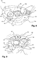
- One of these locking means 50 is shown in addition great detail on the figure 8 .
- the locking means 50 comprises a clamp 60 having two jaws 61, 62 articulated around a pivot connection, for example formed by a screw 63 for fixing the jaws 61, 62 on the coupling part 10.
- the heads of the screws 63 are accessible by traditional tools such as keys.
- the first orifices 30 and the second orifices 40 are configured to cooperate, respectively, with first pins 70 and second pins 80, projecting from the outer face 21 of the annular casing 2.
- the first pins 70 and the second pins 80 are arranged on the annular casing 2 so as to form two annular rows.
- the first pins 70 and the second pins 80 are arranged separately on these annular rows so as to form several groups, the number of groups corresponding to the number of clamps 60 of the support interface 1, each group comprising at least one first pin 70 frustoconical allowing the attachment of a clamp 60 and at least one of these groups comprising a second pin 80 simple cylindrical.
- the groups comprising a second cylindrical pin 80 being configured to be distributed over the various annular rows.
- the annular casing advantageously comprises, in a portion intended to receive a support interface 1 according to the invention, three first pins 70 and two second pins 80, the second pins 80 being positioned close to two of the first three pins 70.
- the first pawns 70 and the second pawns 80 are organized into three groups G1, G2, G3, two G1, G2 of these groups comprising a first pawn 70 and a second pawn 80 ( figure 5 ) and the third group G3 comprising only a first piece 70.
- two second pins 80 are implemented. However, it is conceivable to have only a single second peg 80 out of all the groups of pegs, in particular for an annular casing 2 of a low-power aircraft turbomachine having smaller dimensions and mass.
- the first pins 70 and the second pins 80 are engaged from an inner face 22 of the annular casing 2, respectively in orifices 23, 24 made for this purpose in the annular casing 2, and are shrunk in the annular casing 2.
- the first pins 70 comprise a base 71, a cylindrical body 72 having a thinned portion 73 and a free end 74 connected to the thinned portion 73 by a frustoconical surface 75.
- the base 71 of the first pins 70 constitutes a widened end with respect to their cylindrical body 72. This base 71 is capable of being engaged in a counterbore 230 provided on the internal face of the annular casing 2 at the inlet of the orifices 23 for receiving the first pins 70.
- the second pegs 80 comprise a base 81 and a cylindrical body 82 provided with an axial bore 83 and a free end 84.
- the axial bore 83 is not threaded and allows the attachment of a tool for shrinking the second pegs 80 in the annular casing 2.
- the base 81 of the second pins 80 constitutes an enlarged end with respect to their cylindrical body 82. This base 81 is capable of being engaged in a housing 240 provided on the internal face of the annular casing 2 at the inlet of the orifices 24 for receiving the second pawns 80.
- the base 81 of the second pawns 80 has a frustoconical shape and the housings 240 for receiving these bases 81 have a complementary shape with a frustoconical surface.
- the complementary frustoconical shapes of the base 81 of the second pins 80 and of the housings 240 for receiving these bases 81 make it possible to locally increase the contact surface between the second pins 80 and the annular casing 2, this despite a low skin thickness of the shell of the annular casing 2.
- the base 81 of the second pins 80 bears conically against the annular casing 2, thus increasing the shear recovery support surface and allowing the second pins 80 to help take up forces shear induced when the motor is suspended through the support interfaces 1, as will be explained in more detail below.
- the first pawns 70 and the second pawns 80 are required to withstand significant mechanical stresses, in particular load stresses of the order of 9G, during the handling or transport of the annular casing 2. Indeed, for obvious reasons , the annular casing 2 must not be able to detach from a support device 100 (detailed below) during its handling or transport. To reinforce them and thus prevent their tearing during use, they each comprise a retaining ring, respectively 90, 91, making it possible to locally increase their respective thickness and thus their robustness.
- These rings 90, 91 have an annular skirt 90a, 91a with a diameter greater than a diameter of said rings 90, 91, one underside of these annular skirts 90a, 91a being positioned on the outer face 21 of the annular casing 2.
- the second pins 80 are configured to be inserted into the second orifices 40 of the coupling part 10 of the support interfaces 1 by their free end 84.
- Their cylindrical body 82 ensures the centering of the coupling part 10 of the support interface 1 and its correct positioning on the annular casing 2.
- the first pins 70 are configured to be inserted into the first orifices 30 of the coupling part 10 of the support interfaces 1 via their free end 74.
- Their thinned portion 73 as well as their frustoconical surface 75 being configured to cooperate with the locking means 50 to ensure the plating and the temporary fixing of the support interface 1 on the annular casing 2, as will be explained in more detail below.
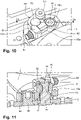
- the clamps 60 are movable between an open position and a closed position.
- the jaws 61, 62 are separated from each other and allow the engagement and disengagement of a first pin 70 carried by the annular casing 2 of a first orifice 30 of the coupling part 10 of the support interface 1.
- a second pin 80 carried by the annular casing 2 can be engaged and disengaged from a second orifice 40 of the coupling part 10 of the support interface 1 .
- the jaws 61, 62 are close together so as to surround and grip a first pin 70 at its thinned portion 73.
- the jaws 61, 62 of the clamp 60 define, in the closed position, a hole having a funnel shape, namely a portion of circular section surmounted by a frustoconical portion, in order to be able to match an outer surface defined by the thinned portion 73 and the frustoconical surface 75 of the first pins 70.
- the portion of circular section of the funnel shape is positioned opposite the thinned portion 73 of the first pin 70 and the frustoconical portion of the funnel hole is positioned opposite the frustoconical surface 75 of the first pin 70.
- the clamp 60 is then locked.
- the jaws 61, 62 of each clamp 60 have, at their free ends 61a, 62a (namely their ends opposite those carrying the screw 63 providing the pivot connection of the jaws 61, 62), holes 61b, 62b receiving a screw 64 ensuring the locking of the clamp 60 in the closed position.
- the locking screw 64 of the clamp 60 is a ball-and-socket screw making it possible to prevent it from bending during its tightening.
- the heads of the screws 64 are accessible by traditional tools such as keys.
- the first pins 70 are blocked by the jaws 61, 62 in the first orifices 30 and the coupling part 10 is pressed against the outer face 21 of the annular casing 2, as shown in figure 7 . And, consequently, the second pins 80 are also blocked in the second orifices 40.
- the locking means 50 and in particular the clamps 60 thus ensure the pressing and the fixing in position of the support interface 1 on the annular casing 2 by a double system, namely a clamping system by cone (conical support at the level of the frustoconical surface 75) and a clamping system by screw (with the screw 64 for locking the jaws 61, 62), which increases the robustness of the fixing of the support interface 1 on the annular casing 2.
- At least one support interface 1, and preferably two support 1 are approached from the annular casing.
- the internal faces 12 of the support interfaces 1 are positioned facing the external face 21 of the annular casing 2.
- the first orifices 30 of the coupling piece 10 of each support interface 1 are positioned aligned on the first pins 70 of the annular casing 2 and the second orifices 40 of the coupling piece 10 of each support interface 1 are positioned aligned on the second pins 80 of the annular casing 2.
- the clamps 60 are then presented in the open position.
- the support interfaces 1 are then applied to the annular casing 2, in a diametrically opposite manner, so that the first pins 70 of the annular casing 2 pass through the first orifices 30 of the coupling piece 10 of each support interface 1 and that the second pins 80 of the annular casing 2 are engaged in the second orifices 40 of the coupling part 10 (and pass through these second orifices 40 in the case of through orifices, therefore not blind) of each support interface 1.
- the clamps 60 fixed on the support interface 1 by the screw 63, are then closed on the first pins 70 by rotation of the jaws 61, 62 around their pivot connection formed by the screw 63 so as to tighten the coupling part 10 of each support interface 1 on the annular casing 2.
- the locking screw 64 is screwed into the holes 61b, 62b provided in the ends 61a and 62a of the jaws 61, 62 in order to lock the clamp 60 in the closed position and to immobilize the coupling part 10 of each support interface 1 on the annular housing 2.
- a support device 100 can then be approached to the annular casing 2.
- the support arms 210, 220 are positioned substantially opposite the interfaces of support 1 fixed on the annular casing 2.
- the ends of the arms 210, 220 of the support device 100 are inserted and fixed to the attachment elements 20a of the support interfaces 1.
- the attachment elements 20a of the support interfaces 1 are by example provided with threads allowing the screwing of the ends of the arms 210, 220 also provided with threads.
- the annular casing 2 is then connected to the support device 100 and can be held securely in a desired position and moved by acting on movement means known per se allowing the movement of the support arms 210, 220 of the support device 100 Hooks of the support device 100 can also be passed through the projecting orifices of the second attachment elements 20b of the support interfaces 1 for the suspension of the annular casing 2.
- the ends of the arms 210, 220 of the support device 100 are removed from the attachment elements 20a, the hooks of the support device 100 are removed from the second attachment elements 20b if necessary , the locking screws 64 are removed to release the jaws 61, 62, the clamps 60 are opened and the support interfaces 1 are removed from the annular casing 2.
- the support interfaces 1 intended to be positioned on either side of the annular casing 2 with a view to the suspension of the latter may be identical in all respects.
- the support interfaces 1 can have symmetrical arrangements in order to be adapted, each, to geometric constraints which can be different depending on the side of the annular casing 2 that they are required to equip.
- the support interfaces 1 are executed in any material having the robustness necessary for its function. They are for example made of steel.
- the annular casing 2 provided with first pins 70 and second pins 80 and the support interfaces 1 configured to cooperate with the first and second pins 70, 80 of the annular casing 2 thus constitute a robust assembly allowing the simple and secure handling of a annular casing 2.
- a turbomachine T comprising such an annular casing 2 according to the invention can thus be assembled and disassembled several times throughout its lifetime, without risk. Indeed, the clamp locking 60 of the support interface 1 according to the invention does not induce wear at the level of the pins 70, 80 of the annular casing 2 as is the case with the threaded pins of the prior art.
- the jaws of the clamp are no longer articulated around a pivot connection but are arranged parallel to one another and can slide to pass from the open position to the closed position and vice versa.
- the two jaws 121 and 122 of the gripper 120 extend longitudinally along axes Za and Zb which are parallel to each other and at least one of the jaws can be translated perpendicularly to these axes so as to move the clamp from the open position to the closed position or vice versa.
- the translation is obtained by rotation of the clamping screws 123 and 124.
- such a translation can be obtained by rotation of at least one clamping screw which passes through the two jaws along the axis of the desired translation.
- the two jaws have threaded holes complementary to the thread of the clamping screw or screws.
- a particular advantage of the present invention is that all the elements which can undergo wear during use such as the threads are on the support interface 1 and no longer on an element of the annular casing 2. In this way and contrary to the devices of the prior art where it was necessary to immobilize and intervene on a turbomachine, it is simpler and less expensive to replace a support interface 1 according to the invention if the latter is no longer functional.
Landscapes
- Engineering & Computer Science (AREA)
- Mechanical Engineering (AREA)
- General Engineering & Computer Science (AREA)
- Transportation (AREA)
- Manufacturing & Machinery (AREA)
- Aviation & Aerospace Engineering (AREA)
- Structures Of Non-Positive Displacement Pumps (AREA)
- Connection Of Plates (AREA)
- Turbine Rotor Nozzle Sealing (AREA)
Description
La présente invention concerne une interface de support. Plus particulièrement, l'invention concerne une interface de support pour carter moteur, notamment d'un moteur aéronautique comme une turbomachine, qui soit adapté à être utilisé lors de la fabrication ou de la manutention du moteur.The present invention relates to a support interface. More particularly, the invention relates to a support interface for an engine casing, in particular of an aeronautical engine such as a turbomachine, which is adapted to be used during the manufacture or handling of the engine.
L'invention concerne également un carter annulaire de turbomachine configuré pour recevoir une telle interface de support. Elle concerne également un ensemble comprenant un tel carter annulaire et une telle interface de support, ainsi qu'une turbomachine comportant un tel ensemble. La présente invention concerne enfin un procédé de manutention d'un tel carter à l'aide d'une telle interface de support.The invention also relates to an annular turbomachine casing configured to receive such a support interface. It also relates to an assembly comprising such an annular casing and such a support interface, as well as a turbomachine comprising such an assembly. The present invention finally relates to a method for handling such a casing using such a support interface.
L'état de l'art comprend les documents
Lors de la manutention des turbomachines, par exemple lors de leur assemblage ou de procédures de maintenance, il est souvent nécessaire de les soutenir dans une position élevée afin de permettre un accès plus aisé à leurs différents composants.When handling turbomachines, for example during their assembly or maintenance procedures, it is often necessary to support them in an elevated position in order to allow easier access to their various components.
Dans la technique actuelle, au moins deux cavités de réception sont ménagées dans le carter annulaire des turbomachines. Ces cavités, diamétralement opposées, sont configurées pour recevoir l'extrémité d'un bras support solidaire d'un bâti. Pour soutenir le moteur, un bras support est ainsi introduit dans chaque cavité et fixé au carter de sorte à suspendre et maintenir le carter annulaire dans une position souhaitée. De la sorte, pour assurer un bon maintien du carter annulaire, il est nécessaire que chaque cavité de réception présente une profondeur utile suffisante.In the current technique, at least two receiving cavities are arranged in the annular casing of the turbomachines. These cavities, diametrically opposed, are configured to receive the end of a support arm secured to a frame. To support the motor, a support arm is thus introduced into each cavity and fixed to the casing so as to suspend and maintain the annular casing in a desired position. In this way, to ensure good retention of the annular casing, it is necessary for each receiving cavity to have a sufficient useful depth.
Pour obtenir une telle profondeur, le carter annulaire est muni de surépaisseurs locales, aussi appelées bossages, dans lesquelles sont usinées les cavités de réception pour les bras support.To obtain such a depth, the annular casing is provided with local thickenings, also called bosses, in which the reception cavities for the support arms are machined.
Ces surépaisseurs entraînent une augmentation du poids du moteur. Or, pour des raisons évidentes de rendement, il est souhaitable que le poids du moteur soit minimisé d'autant plus que ces surépaisseurs ne sont pas destinées à être utilisées pendant les phases de vol des aéronefs.These extra thicknesses lead to an increase in the weight of the engine. Now, for obvious efficiency reasons, it is desirable for the weight of the engine to be minimized, especially since these extra thicknesses are not intended to be used during the flight phases of aircraft.
Afin de résoudre ce problème, des interfaces de support ont été proposées comprenant une pièce de couplage avec une face externe et une face interne, la face externe de cette pièce de couplage présentant une cavité apte à recevoir un bras de support, et la face interne de cette pièce de couplage étant apte à être montée sur une face externe d'un carter annulaire.In order to solve this problem, support interfaces have been proposed comprising a coupling part with an external face and an internal face, the external face of this coupling part having a cavity able to receive a support arm, and the internal face of this coupling piece being adapted to be mounted on an outer face of an annular casing.
Par exemple, le document
La présente invention propose une solution simple et efficace de maintien en suspension des carters annulaires de turbomachines.The present invention proposes a simple and effective solution for maintaining the annular casings of turbomachines in suspension.
A cet effet, l'invention concerne une interface de support amovible pour un carter annulaire de turbomachine, le carter annulaire comprenant des premiers pions en saillie sur une face externe, ces pions comportant une portion amincie et une extrémité libre reliée à la portion amincie par une surface tronconique, l'interface de support comprenant une pièce de couplage apte à être montée sur le carter annulaire, et au moins un élément d'accrochage en vue de la suspension du carter annulaire, des orifices ménagés dans la pièce de couplage, cette interface comporte en outre des moyens de verrouillage de la pièce de couplage sur le carter annulaire, ces moyens de verrouillage étant positionnés sur la pièce de couplage et comprenant, chacun, une pince présentant deux mâchoires, chaque pince étant mobile depuis une position ouverte dans laquelle un pion porté par le carter peut être engagé et désengagé de l'un desdits orifices et une position fermée dans laquelle le pion est bloqué dans cet orifice.To this end, the invention relates to a removable support interface for an annular casing of a turbomachine, the annular casing comprising first studs projecting from an external face, these studs comprising a thinned portion and a free end connected to the thinned portion by a frustoconical surface, the support interface comprising a coupling part capable of being mounted on the annular casing, and at least one attachment element for the purpose of suspending the annular casing, orifices made in the coupling part, this interface further comprises means for locking the part coupling on the annular casing, these locking means being positioned on the coupling piece and each comprising a clamp having two jaws, each clamp being movable from an open position in which a pin carried by the casing can be engaged and disengaged of one of said orifices and a closed position in which the pin is blocked in this orifice.
L'interface de support avec ses moyens de verrouillage selon l'invention constitue un système imperdable présentant l'avantage intéressant d'être simple et rapide d'utilisation.The support interface with its locking means according to the invention constitutes a captive system having the interesting advantage of being simple and quick to use.
De préférence et avantageusement, les mâchoires de la pince définissent un orifice en position fermée présentant une forme en entonnoir.Preferably and advantageously, the jaws of the pliers define an orifice in the closed position having a funnel shape.
Ainsi, les mâchoires épousent en partie la forme d'une surface externe des premiers pions du carter annulaire assurant ainsi une bonne fixation de l'interface de support.Thus, the jaws partially match the shape of an outer surface of the first pins of the annular casing, thus ensuring good fixing of the support interface.
Selon un mode de réalisation, les deux mâchoires de la pince sont articulées autour d'une liaison pivot.According to one embodiment, the two jaws of the clamp are articulated around a pivot connection.
Selon un mode de réalisation, la liaison pivot des mâchoires de la pince est formée par une vis de fixation des mâchoires sur la pièce de couplage.According to one embodiment, the pivot connection of the jaws of the clamp is formed by a screw fixing the jaws to the coupling part.
Selon un mode de réalisation avantageux, les mâchoires de cette pince présentent, à leurs extrémités libres, des trous de réception d'une vis assurant le verrouillage de la pince dans une position fermée.According to an advantageous embodiment, the jaws of this clamp have, at their free ends, holes for receiving a screw ensuring the locking of the clamp in a closed position.
Selon un mode de réalisation, les deux mâchoires de la pince s'étendent longitudinalement selon des axes respectifs parallèles l'un à l'autre et dans laquelle la pince est configurée pour qu'au moins une des mâchoire puisse être translatée perpendiculairement aux axes des mâchoires depuis la position ouverte vers la position fermée et réciproquement.According to one embodiment, the two jaws of the gripper extend longitudinally along respective axes parallel to each other and in which the gripper is configured so that at least one of the jaws can be translated perpendicularly to the axes of the jaws from the open position to the closed position and vice versa.
Selon un mode de réalisation, la translation d'au moins une mâchoire est obtenue par rotation d'au moins une visse de serrage traversant les deux mâchoires selon l'axe de la translation.According to one embodiment, the translation of at least one jaw is obtained by rotation of at least one tightening screw passing through the two jaws along the axis of the translation.
La présente invention concerne également un carter annulaire de turbomachine d'aéronef apte à coopérer avec une interface de support selon l'invention, comprenant une face interne et une face externe,
- des premiers pions en saillie sur la face externe ;
- ces premiers pions comportant une portion amincie et une extrémité libre reliée à la portion amincie par une surface tronconique et étant aptes à coopérer avec des orifices de l'interface de support selon l'invention.
- first projecting pins on the external face;
- these first pins comprising a thinned portion and a free end connected to the thinned portion by a frustoconical surface and being capable of cooperating with orifices of the support interface according to the invention.
Avantageusement, le carter annulaire comporte en outre :
- des seconds pions en saillie sur la face externe ;
- ces seconds pions étant sensiblement cylindriques et étant aptes à coopérer avec des orifices de l'interface de support selon l'invention.
- second pins projecting from the outer face;
- these second pins being substantially cylindrical and being capable of cooperating with orifices of the support interface according to the invention.
Le carter annulaire selon l'invention présente l'avantage intéressant de n'être équipé que de pions frettés aptes à coopérer de manière simple et efficace avec l'interface de support garantissant une manutention rapide et aisée dudit carter annulaire.The annular casing according to the invention has the interesting advantage of being equipped only with shrink-wrapped pins capable of cooperating in a simple and effective manner with the support interface guaranteeing rapid and easy handling of said annular casing.
La présente invention concerne encore un ensemble comprenant au moins un carter annulaire et une interface de support présentant au moins l'une quelconque des caractéristiques susmentionnées, dans lequel les premiers pions du carter annulaire sont configurés pour traverser des orifices de la pièce de couplage de l'interface de support, les mâchoires de la pince étant configurées pour se refermer sur les premiers pions de façon à serrer la pièce de couplage sur le carter annulaire.The present invention also relates to an assembly comprising at least one annular casing and a support interface having at least any one of the aforementioned characteristics, in which the first pins of the annular casing are configured to pass through orifices of the coupling part of the support interface, the jaws of the clamp being configured to close on the first pins so as to clamp the coupling part on the annular casing.
Ainsi, l'interface de support selon l'invention est plaquée de manière efficace sur le carter annulaire empêchant ainsi un effet de bras levier qui amplifierait les reprises d'efforts au niveau des pions du carter.Thus, the support interface according to the invention is pressed effectively against the annular casing, thus preventing a lever arm effect which would amplify the take-up of forces at the level of the casing pins.
Avantageusement, les seconds pions du carter annulaire sont configurés pour s'engager dans des orifices de la pièce de couplage pour permettre de centrage de l'interface de support sur le carter annulaire.Advantageously, the second pins of the annular casing are configured to engage in orifices of the coupling piece to allow centering of the support interface on the annular casing.
Ainsi, l'interface de support est bien positionnée sur le carter annulaire avant d'être plaquée et verrouillée sur le carter annulaire.Thus, the support interface is well positioned on the annular casing before being flattened and locked on the annular casing.
L'invention concerne encore une turbomachine d'aéronef caractérisée en ce qu'elle comporte un ensemble comprenant l'une des caractéristiques susmentionnées.The invention also relates to an aircraft turbomachine characterized in that it comprises an assembly comprising one of the aforementioned characteristics.
Ainsi, il est aisé d'assembler et de désassembler les différentes portions de carters annulaires constituant la turbomachine, en facilitant ainsi le montage et les interventions de maintenance.Thus, it is easy to assemble and disassemble the various portions of annular casings constituting the turbomachine, thus facilitating assembly and maintenance operations.
L'invention concerne également un procédé de manutention d'un carter annulaire de turbomachine, comprenant les étapes de :
- application d'au moins une interface de support sur le carter annulaire de façon à ce que les premiers pions du carter annulaire traversent des orifices de la pièce de couplage de l'interface de support ;
- fermeture des mâchoires de la pince sur les premiers pions de façon à serrer la pièce de couplage de l'interface de support sur le carter annulaire.
- application of at least one support interface to the annular casing so that the first pins of the annular casing pass through orifices of the coupling part of the support interface;
- closing the jaws of the clamp on the first pins so as to clamp the coupling part of the support interface on the annular casing.
Comme indiqué précédemment, il est aisé et rapide de fixer des interface de support selon l'invention sur un carter annulaire pour en assurer une suspension sécurisée pour tout type d'intervention sur la turbomachine.As indicated previously, it is easy and quick to fix support interfaces according to the invention on an annular casing to ensure secure suspension thereof for any type of intervention on the turbomachine.
La présente invention sera mieux comprise et d'autres détails, caractéristiques et avantages de la présente invention apparaîtront plus clairement à la lecture de la description d'un exemple non limitatif qui suit, en référence aux dessins annexés sur lesquels :
- la
figure 1 est une vue d'ensemble d'un moteur de turbomachine, soutenu par un dispositif de support par l'intermédiaire d'interfaces de support selon l'invention ; - la
figure 2 est une vue en perspective de l'interface de support selon l'invention - la
figure 3 est une vue en perspective montrant notamment la sous-face de l'interface de support selon l'invention ; - la
figure 4 est une vue de détail et en perspective du carter annulaire selon l'invention ; - la
figure 5 est une vue de détail en perspective montrant un premier pion et un second pions équipant le carter annulaire selon l'invention ; - la
figure 6 est une vue en coupe axiale de lafigure 5 ; - la
figure 7 est une vue analogue à lafigure 4 dans laquelle une interface de support est positionnée sur le carter annulaire ; - la
figure 8 une vue de détail et en perspective de l'interface de support montrant la pince ; - la
figure 9 est une vue de détail et en perspective montrant l'interface de support positionnée sur le carter annulaire et dans laquelle la pince est illustrée en position ouverte ; - la
figure 10 est une vue analogue à lafigure 9 dans laquelle la pince est illustrée en position fermée ; - la
figure 11 est une vue en coupe selon l'axe A-A de lafigure 10 ; et, - la
figure 12 est une vue de détail et en perspective d'un mode de réalisation d'une pince d'une interface de support selon l'invention.
- the
figure 1 is an overall view of a turbomachine engine, supported by a support device via support interfaces according to the invention; - the
figure 2 is a perspective view of the support interface according to the invention - the
picture 3 is a perspective view showing in particular the underside of the support interface according to the invention; - the
figure 4 is a detail and perspective view of the annular casing according to the invention; - the
figure 5 is a perspective detail view showing a first pin and a second pin equipping the annular casing according to the invention; - the
figure 6 is an axial sectional view of thefigure 5 ; - the
figure 7 is a view analogous tofigure 4 wherein a support interface is positioned on the annular casing; - the
figure 8 a detail and perspective view of the support interface showing the gripper; - the
figure 9 is a detail and perspective view showing the support interface positioned on the annular casing and in which the clamp is illustrated in the open position; - the
figure 10 is a view analogous tofigure 9 in which the clamp is illustrated in the closed position; - the
figure 11 is a sectional view along the axis AA of thefigure 10 ; and, - the
figure 12 is a detail and perspective view of one embodiment of a clamp of a support interface according to the invention.
Dans le présent exposé, les termes « interne » et « externe » sont utilisés en référence à un positionnement par rapport à l'axe de rotation d'une turbomachine axiale.In the present description, the terms “internal” and “external” are used in reference to a positioning relative to the axis of rotation of an axial turbomachine.
Sur la
Des moyens de déplacement (non représentés) permettent le déplacement de chaque bras de support 210, 220, notamment selon son axe longitudinal Xa, Xb.Movement means (not shown) allow the movement of each
Comme illustré sur la
L'interface de support 1 est montrée en détail aux
Dans l'exemple illustré aux
La pièce de couplage 10 comprend une face externe 11, une face interne 12. Cette face interne 12 est configurée pour être positionnée en regard de la face externe 21 du carter annulaire 2, lorsque l'interface de support 1 est montée sur le carter annulaire 2. Avantageusement, la face interne 12 de la pièce de couplage 10 présente un rayon de courbure analogue à celui de la face externe 21 du carter annulaire 2 afin de permettre un positionnement correct, sans jeu, de l'interface de support 1 sur le carter annulaire 2. Des premiers orifices 30 et des seconds orifices 40 sont ménagés dans la pièce de couplage 10. Les premiers orifices 30 sont traversant depuis la face externe 11 à la face interne 12 de la pièce de couplage 10. Les seconds orifices 40 sont soit traversant depuis la face externe 11 à la face interne 12 de la pièce de couplage 10, soit borgnes, autrement dit ils sont ménagés dans la face interne 12 de la pièce de couplage 10 et ne débouchent alors pas sur la face externe 11 de la pièce de couplage 10. Notamment, les premiers orifices 30 et les seconds orifices 40 sont ménagés dans des portions élargies 10a de la pièce de couplage 10The
Les éléments d'accrochage en vue de la manutention du carter annulaire 2 comprennent des orifices 20a ménagés dans la pièce de couplage 10. Les extrémités des bras de support 210, 220 du dispositif de support 100 comportent alors une portion distale de section constante cylindrique, ici à profil circulaire, aptes à s'engager dans les orifices 20a.The attachment elements for the handling of the
La pièce de couplage 10 comporte encore un second élément d'accrochage 20b en vue de la suspension du carter annulaire 2 faisant saillie à partir de la face externe 11 de la pièce de couplage 10. Cet élément d'accrochage pointé 20b permet de suspendre le carter annulaire 2 par l'intermédiaire d'un crochet de manutention du dispositif de support 100, permettant notamment de soulever le carter annulaire 2 par exemple pour son accostage sur un aéronef.The
L'interface de support 1 comporte encore, sur la face externe de la pièce de couplage 10, des moyens de verrouillage 50 de la pièce de couplage 10 sur le carter annulaire 2. L'un de ces moyens de verrouillage 50 est montré en plus grand détail sur la
Les premiers orifices 30 et les seconds orifices 40 sont configurés pour coopérer, respectivement, avec des premiers pions 70 et des seconds pions 80, ménagés en saillie sur la face externe 21 du carter annulaire 2.The
Avantageusement, les premiers pions 70 et les seconds pions 80 sont agencés sur le carter annulaire 2 de sorte à former deux rangées annulaire. Les premiers pions 70 et les seconds pions 80 sont agencés séparés sur ces rangées annulaires de sorte à former plusieurs groupes, le nombre de groupe correspondant au nombre de pinces 60 de l'interface de support 1, chaque groupe comprenant au moins un premier pion 70 tronconique permettant la fixation d'une pince 60 et au moins l'un de ces groupes comprenant un second pion 80 simple cylindrique. Les groupes comprenant un second pion 80 cylindrique étant configurés pour être répartis sur les différentes rangées annulaires.Advantageously, the
Selon l'exemple de réalisation illustré à la
En effet, l'environnement du carter annulaire 2 est très contraint de sorte qu'il peut être difficile d'intégrer un troisième second pion 80. De plus, l'utilisation de deux seconds pions 80 cylindriques pour trois groupes de pions suffisent à assurer la tenue mécanique de l'interface de support 1. Il est également à noter que l'ajout d'un troisième second pion 80 rendrait le montage hyperstatique contraignant ainsi l'assemblage, un tel montage hyperstatique nécessiterait en effet d'importants jeux pour autoriser le montage de l'interface de support 1 sur le carter annulaire 2, ce qui annulerait par conséquent l'un des intérêts des pions secondaires 80, à savoir l'aide à la reprise des forces de cisaillement (décrit ci-après).Indeed, the environment of the
Dans l'exemple de réalisation illustré, deux seconds pions 80 sont mis en œuvre. Toutefois, il est envisageable de n'avoir qu'un unique second pion 80 sur l'ensemble des groupes de pions, notamment pour un carter annulaire 2 d'une turbomachine d'aéronef de faible puissance présentant des dimensions et une masse moindre.In the illustrated embodiment, two
En référence aux
Les seconds pions 80 comprennent une base 81 et un corps cylindrique 82 muni d'un alésage axial 83 et une extrémité libre 84. L'alésage axial 83 est non taraudé et permet la fixation d'un outil pour le frettage des seconds pions 80 dans le carter annulaire 2. La base 81 des seconds pions 80 constitue une extrémité élargie par rapport à leur corps cylindrique 82. Cette base 81 est apte à être engagée dans un logement 240 prévu sur la face interne du carter annulaire 2 en entrée des orifices 24 de réception des seconds pions 80. Avantageusement, la base 81 des seconds pions 80 présente une forme tronconique et les logements 240 de réception de ces bases 81 présentent une forme complémentaire de surface tronconique. Les formes tronconiques complémentaires de la base 81 des seconds pions 80 et des logements 240 de réception de ces bases 81 permettent d'augmenter localement la surface de contact entre les seconds pions 80 et le carter annulaire 2, ceci malgré une faible épaisseur de peau de la virole du carter annulaire 2. Ainsi, la base 81 des seconds pions 80 est en appui conique contre le carter annulaire 2 augmentant ainsi la surface d'appui de reprise de cisaillement et permettant aux seconds pions 80 d'aider à la reprise de forces de cisaillement induites lorsque le moteur est suspendu par l'intermédiaire des interfaces de support 1, comme il sera expliqué plus en détail ci-après.The second pegs 80 comprise a
Les premiers pions 70 et le seconds pions 80 sont amenés à supporter d'importantes contraintes mécaniques, notamment des contraintes de charge de l'ordre de 9G, lors de la manutention ou du transport du carter annulaire 2. En effet, pour des raisons évidentes, le carter annulaire 2 ne doit pas pouvoir se détacher d'un dispositif de support 100 (détaillé ci-après) lors de sa manutention ou de son transport. Pour les renforcer et ainsi éviter leur arrachement en cours d'utilisation, ils comportent, chacun, une bague de maintien, respectivement 90, 91, permettant d'augmenter localement leur épaisseur respective et ainsi, leur robustesse. Ces bagues 90, 91 présentent une jupe annulaire 90a, 91a d'un diamètre supérieur à un diamètre desdites bagues 90, 91, une sous face de ces jupes annulaires 90a, 91a étant positionnée sur la face externe 21 du carter annulaire 2.The
Les seconds pions 80 sont configurés pour être insérés dans les seconds orifices 40 de la pièce de couplage 10 des interfaces de support 1 par leur extrémité libre 84. Leur corps cylindrique 82 assure le centrage de la pièce de couplage 10 de l'interface de support 1 et son bon positionnement sur le carter annulaire 2.The second pins 80 are configured to be inserted into the
Les premiers pions 70 sont configurés pour être insérés dans les premiers orifices 30 de la pièce de couplage 10 des interfaces de support 1 par leur extrémité libre 74. Leur portion amincie 73 ainsi que leur surface tronconique 75 étant configurés pour coopérer avec les moyens de verrouillage 50 pour assurer le plaquage et la fixation temporaire de l'interface de support 1 sur le carter annulaire 2, comme il sera expliqué plus en détail ci-après.The first pins 70 are configured to be inserted into the
Les pinces 60 sont mobiles entre une position ouverte et une position fermée.The
En référence à la
En référence aux
En position fermée et verrouillée des pinces 60, les premiers pions 70 sont bloqués par les mâchoires 61, 62 dans les premiers orifices 30 et la pièce de couplage 10 est plaquée contre la face externe 21 du carter annulaire 2, comme représenté à la
Les moyens de verrouillage 50 et notamment les pinces 60 assurent ainsi le plaquage et la fixation en position de l'interface de support 1 sur le carter annulaire 2 par un double système à savoir un système de serrage par cône (appui conique au niveau de la surface tronconique 75) et un système de serrage par vis (avec la vis 64 de verrouillage des mâchoires 61, 62), ce qui augmente la robustesse de la fixation de l'interface de support 1 sur le carter annulaire 2.The locking means 50 and in particular the
Lors de la manutention d'un carter annulaire 2, par exemple en vue de l'assemblage d'une turbomachine T ou d'une procédure de maintenance de cette turbomachine T, au moins une interface de support 1, et de préférence deux interfaces de support 1 sont approchées du carter annulaire. Les faces internes 12 des interfaces de support 1 sont positionnée en regard de la face externe 21 du carter annulaire 2. Les premiers orifices 30 de la pièce de couplage 10 de chaque interface de support 1 sont positionnés alignés sur les premiers pions 70 du carter annulaire 2 et les seconds orifices 40 de la pièce de couplage 10 de chaque interface de support 1 sont positionnés alignés sur les seconds pions 80 du carter annulaire 2. Les pinces 60 sont alors présentées en position ouverte.When handling an
Les interfaces de support 1 sont ensuite appliquées sur le carter annulaire 2, de manière diamétralement opposée, de sorte que les premiers pions 70 du carter annulaire 2 traversent les premiers orifices 30 de la pièce de couplage 10 de chaque interface de support 1 et que les seconds pions 80 du carter annulaire 2 sont engagés dans les seconds orifices 40 de la pièce de couplage 10 (et traversent ces seconds orifices 40 dans le cas d'orifices traversant, donc non borgnes) de chaque interface de support 1.The support interfaces 1 are then applied to the
Les pinces 60, fixée sur l'interface de support 1 par la vis 63, sont alors fermées sur les premiers pions 70 par rotation des mâchoires 61, 62 autour de leur liaison pivot constituée par la vis 63 de façon à serrer la pièce de couplage 10 de chaque interface de support 1 sur le carter annulaire 2.The clamps 60, fixed on the
Enfin, la vis 64 de verrouillage est vissée dans les trous 61b, 62b ménagés dans les extrémités 61a et 62a des mâchoires 61, 62 afin de verrouiller la pince 60 en position fermée et d'immobiliser la pièce de couplage 10 de chaque interface de support 1 sur le carter annulaire 2.Finally, the locking
Un dispositif de support 100 peut alors être approché du carter annulaire 2. Les bras de support 210, 220 sont positionnés sensiblement en regard des interfaces de support 1 fixées sur le carter annulaire 2. Les extrémités des bras 210, 220 du dispositif de support 100 sont insérées et fixées aux éléments d'accrochage 20a des interfaces de support 1. Les éléments d'accrochage 20a des interfaces de support 1 sont par exemple munis de filets permettant le vissage des extrémités des bras 210, 220 également munis de filets.A
Le carter annulaire 2 est alors relié au dispositif de support 100 et peut être maintenu de manière sécurisée dans une position souhaité et déplacé par action sur des moyens de déplacements connus en soi permettant le déplacement des bras de support 210, 220 du dispositif de support 100. Des crochets du dispositif de support 100 peuvent également être passés dans les orifices en saillie des seconds éléments d'accrochage 20b des interfaces de support 1 pour la suspension du carter annulaire 2.The
Lorsque la manutention du carter annulaire 2 est terminée, les extrémités des bras 210, 220 du dispositif de support 100 sont retirées des éléments d'accrochage 20a, les crochets du dispositif de support 100 sont retirés des seconds éléments d'accrochage 20b le cas échéant, les vis de verrouillage 64 sont retirées pour libérer les mâchoires 61, 62, les pinces 60 sont ouvertes et les interfaces de support 1 sont déposées du carter annulaire 2.When the handling of the
On notera ici que les interfaces de support 1 destinées à être positionnées de part et d'autre du carter annulaire 2 en vue de la suspension de ce dernier peuvent être identiques en tous points. Avantageusement, les interfaces de support 1 peuvent présenter des arrangements symétriques afin d'être adaptées, chacune, à des contraintes géométriques qui peuvent être différentes selon le côté du carter annulaire 2 qu'elles sont amenées à équiper. Les interfaces de support 1 sont exécutées en tout matériaux présentant la robustesse nécessaire à sa fonction. Elles sont par exemple réalisées en acier.It will be noted here that the support interfaces 1 intended to be positioned on either side of the
Le carter annulaire 2 munis de premiers pions 70 et de seconds pions 80 et les interfaces de support 1 configurées pour coopérer avec les premiers et seconds pions 70, 80 du carter annulaire 2 constituent ainsi un ensemble robuste permettant la manutention simple et sécurisée d'un carter annulaire 2. Une turbomachine T comprenant un tel carter annulaire 2 selon l'invention peut ainsi être assemblée et désassemblée à plusieurs reprises tout au long de sa durée de vie, sans risque. En effet, le verrouillage par pince 60 de l'interface de support 1 selon l'invention n'induit pas d'usure au niveau des pions 70, 80 du carter annulaire 2 comme c'est le cas avec les pions taraudés de l'art antérieur.The
Dans un mode de réalisation alternatif de l'interface de support, décrit en référence à la
Un avantage particulier de la présente invention est que tous les éléments pouvant subir une usure à l'usage tel que les filets sont sur l'interface de support 1 et non plus sur un élément du carter annulaire 2. De la sorte et contrairement aux dispositifs de l'art antérieur où il était nécessaire d'immobiliser et d'intervenir sur une turbomachine, il est plus simple et moins couteux de remplacer une interface de support 1 selon l'invention si cette dernière n'est plus fonctionnelle.A particular advantage of the present invention is that all the elements which can undergo wear during use such as the threads are on the
Claims (13)
- A removable support interface (1) for an annular casing (2) of a turbomachine (T), an annular casing (2) of an aircraft turbomachine (T), comprising first pins (70) projecting from an outer face (21), these first pins (70) comprising a thinned portion (73) and a free end (74) connected to the thinned portion (73) by a frustoconical surface (75), the removable support interface (1) comprising a coupling part (10) which can be mounted on the annular casing (2), and at least one attachment element (20a, 20b) for suspending the annular casing (2), orifices (30) provided in the coupling part (10), this interface comprises means (50) for locking the coupling part (10) to the annular casing (2), these locking means being positioned on the coupling part (10)
the removable support interface (1) being characterised in that the means (50) comprise each a clamp (60) having two jaws (61, 62, 121, 122), each clamp (60, 120) being movable from an open position in which one of the pins (70) supported by the casing (2) can be engaged and disengaged from one of said orifices (30) and a closed position in which the pin (70) is immobilized in this orifice (30). - The support interface (1) according to claim 1, the jaws (61, 62, 121, 122) of the clamp (60, 120) define an orifice in the closed position having a funnel shape.
- The support interface (1) according to one of the preceding claims, in which the two jaws (61, 62) of the clamp (60) are hinged about a pivot connection.
- The support interface (1) according to claim 3, in which the pivot connection of the jaws (61, 62) of the clamp (60) is formed by a screw (63) for fixing the jaws (61, 62) to the coupling part (10).
- The support interface (1) according to any one of claims 3 or 4, in which the jaws (61, 62) of this clamp (60) have, at their free ends (61a, 62a), holes (61b, 62b) for receiving a screw (64) which locks the clamp (60) in a closed position.
- The support interface (1) according to one of claims 1 and 2, in which the two jaws (121, 122) of the clamp (120) extend longitudinally along respective axis (Za, Zb) parallel to each other and in which the clamp is configured so that at least one of the jaws can be translated perpendicularly to the axis of the jaws from the open position to the closed position and vice versa.
- The support interface (1) according to claim 6, in which the translation of at least one jaw is obtained by rotation of at least one clamping screw (123, 124) passing through both jaws along the axis of the translation.
- An annular casing (2) of an aircraft turbomachine (T) able to cooperate with a support interface (1) according to any one of claims 1 to 7, comprising an inner face (22) and an outer face (21), first pins (70) projecting from the outer face (21);
characterised in that these first pins (70) comprise a thinned portion (73) and a free end (74) connected to the thinned portion (73) by a frustoconical surface (75) and being able to cooperate with orifices (30) of the support interface (1). - The annular casing (2) according to claim 8, characterised in that it further comprises:- second pins (80) projecting from the outer face (21);- these second pins (80) being substantially cylindrical and being capable of cooperating with orifices (40) of the support interface (1) according to any one of claims 1 to 7.
- An assembly comprising an annular casing (2) according to one of claims 8 or 9 and at least one support interface (1) according to any one of claims 1 to 7, in which the first pins (70) of the annular casing (2) are configured to pass through the orifices (30) of the coupling part (10) of the support interface (1), the jaws (61, 62) of the clamp (60) being configured to close on the first pins (70) so as to clamp the coupling part (10) to the annular casing (2).
- The assembly according to claim 10, wherein the second pins (80) of the annular casing (2) are configured to engage in orifices (40) of the coupling part (10) to enable the support interface (1) to be centred on the annular casing (2).
- An aircraft turbomachine (T) characterised in that it comprises an assembly according to one of claims 10 or 11.
- A method of handling an annular casing (2) of a turbomachine (T) according to claim 12, comprising the steps of:- applying of at least one support interface (1) to the annular casing (2) so that the first pins (70) of the annular casing (2) pass through orifices (30) of the coupling part (10) of the support interface (1);- closing the jaws (61, 62) of the clamp (60) on the first pins (70) so as to clamp the coupling part (10) of the support interface (1) to the annular casing (2).
Applications Claiming Priority (2)
| Application Number | Priority Date | Filing Date | Title |
|---|---|---|---|
| FR1858159A FR3085710B1 (en) | 2018-09-12 | 2018-09-12 | REMOVABLE SUPPORT INTERFACE FOR TURBOMACHINE ANNULAR CASE |
| PCT/FR2019/052123 WO2020053530A1 (en) | 2018-09-12 | 2019-09-12 | Removable support interface for an annular turbomachine casing |
Publications (2)
| Publication Number | Publication Date |
|---|---|
| EP3850195A1 EP3850195A1 (en) | 2021-07-21 |
| EP3850195B1 true EP3850195B1 (en) | 2022-10-26 |
Family
ID=63834293
Family Applications (1)
| Application Number | Title | Priority Date | Filing Date |
|---|---|---|---|
| EP19787040.5A Active EP3850195B1 (en) | 2018-09-12 | 2019-09-12 | Removable support interface for an annular turbomachine casing |
Country Status (5)
| Country | Link |
|---|---|
| US (1) | US11525373B2 (en) |
| EP (1) | EP3850195B1 (en) |
| CN (1) | CN112739888B (en) |
| FR (1) | FR3085710B1 (en) |
| WO (1) | WO2020053530A1 (en) |
Family Cites Families (14)
| Publication number | Priority date | Publication date | Assignee | Title |
|---|---|---|---|---|
| US2825477A (en) * | 1953-09-04 | 1958-03-04 | Henry M Ross | Engine work stand and method of using the same |
| US5005276A (en) * | 1990-01-05 | 1991-04-09 | Westinghouse Electric Corp. | Apparatus for accurately assembling large scale machine parts |
| US5435124A (en) * | 1994-08-10 | 1995-07-25 | United Technologies Corporation | Mounting bracket for an aircraft engine accessory |
| FR2917710A1 (en) * | 2007-06-22 | 2008-12-26 | Aircelle Sa | FIXING PLATE AND LONGERON FOR HANDLING THE MONOBLOC PROPULSIVE ASSEMBLY OF AN AIRCRAFT |
| EP2450562B1 (en) * | 2010-11-09 | 2015-06-24 | Openhydro IP Limited | A hydroelectric turbine recovery system and a method therefore |
| US9038253B2 (en) * | 2011-04-29 | 2015-05-26 | General Electric Company | System and method for lifting a casing section |
| US8789866B2 (en) * | 2011-07-27 | 2014-07-29 | General Electric Company | System and method for supporting a shaft inside a turbine |
| FR3017112B1 (en) | 2014-02-03 | 2017-09-29 | Snecma | TRANSPORT AND HINGING STRUCTURE FOR TURBOMACHINE |
| FR3018773B1 (en) * | 2014-03-21 | 2017-12-29 | Snecma | SUPPORT DEVICE |
| FR3041376B1 (en) * | 2015-09-17 | 2017-11-17 | Snecma | INTERFACE AND SUPPORT DEVICE FOR CRANKCASE |
| FR3051834B1 (en) * | 2016-05-27 | 2020-01-24 | Safran Aircraft Engines | HANDLE MOBILE HANGER FOR A TURBOMACHINE HOUSING |
| FR3051833B1 (en) * | 2016-05-27 | 2018-05-18 | Safran Aircraft Engines | REMOVABLE HANDLING BRACKET FOR A TURBOMACHINE HOUSING |
| US10047635B2 (en) * | 2016-06-02 | 2018-08-14 | General Electric Company | Support assembly for turbine shipping/operation |
| FR3061480B1 (en) * | 2016-12-30 | 2019-05-31 | Airbus Operations | AIRCRAFT ENGINE ASSEMBLY COMPRISING A FRONT ENGINE ATTACHMENT FACILITATING ITS ASSEMBLY |
-
2018
- 2018-09-12 FR FR1858159A patent/FR3085710B1/en active Active
-
2019
- 2019-09-12 CN CN201980061356.7A patent/CN112739888B/en active Active
- 2019-09-12 US US17/274,742 patent/US11525373B2/en active Active
- 2019-09-12 WO PCT/FR2019/052123 patent/WO2020053530A1/en unknown
- 2019-09-12 EP EP19787040.5A patent/EP3850195B1/en active Active
Also Published As
| Publication number | Publication date |
|---|---|
| CN112739888A (en) | 2021-04-30 |
| EP3850195A1 (en) | 2021-07-21 |
| FR3085710A1 (en) | 2020-03-13 |
| FR3085710B1 (en) | 2020-09-11 |
| WO2020053530A1 (en) | 2020-03-19 |
| US11525373B2 (en) | 2022-12-13 |
| CN112739888B (en) | 2023-07-21 |
| US20220099002A1 (en) | 2022-03-31 |
Similar Documents
| Publication | Publication Date | Title |
|---|---|---|
| CA2697128C (en) | Riveting screw tack and use thereof for temporarily fixing a boring grid to elements to be assembled | |
| EP1950392B1 (en) | Device for assembling two units, for example for a turbomachine stator | |
| WO2005066534A1 (en) | Quick coupling device | |
| EP3350420B1 (en) | Engine crankcase supporting device and interface | |
| FR2605586A1 (en) | BLADE HOLDER FOR LARGE-SIZED PROPELLER BLADES | |
| WO2013128123A1 (en) | Method for holding an adapter piece on a tubular housing of a turbo engine, and corresponding adapter piece and holding system | |
| FR3033018A1 (en) | TUBULAR ELEMENT SUPPORT PART, IN PARTICULAR FOR AN AIRCRAFT. | |
| FR2624313A1 (en) | ||
| EP3623646B1 (en) | Linking device with single shearing provided with an off-centre axis and an off-centre sleeve, mechanical assembly comprising such a device and assembly method | |
| EP2058476A1 (en) | Connection of radial struts to a circular casing by interleaving inserts | |
| FR3086016A1 (en) | DUAL SHEAR CONNECTION DEVICE HAVING AN ECCENTRIC AXIS AND ECCENTRIC SLEEVES, MECHANICAL ASSEMBLY COMPRISING SUCH A DEVICE AND ASSEMBLY METHOD | |
| FR3046137A1 (en) | METHOD FOR ALIGNING A FIRST ORIFICE OF A FIRST PART WITH A SECOND ORIFICE OF A SECOND PART AND KIT FOR IMPLEMENTING IT | |
| EP3176650B1 (en) | Protection of a timepiece component with micro-machinable material | |
| EP3850195B1 (en) | Removable support interface for an annular turbomachine casing | |
| EP2058477A1 (en) | Connection of radial struts to a circular casing by pins and spacers | |
| EP0018252A1 (en) | Suspension device for a propulsive unit attached to the fuselage of an aircraft, equipment and method of putting it into use | |
| EP2392750B1 (en) | Tie for removably supporting and attaching a structure to a wall, provided with an adapter | |
| EP4180181A1 (en) | Device for mounting/dismounting a connecting pin for a butt joint of two structural elements | |
| EP0285512B1 (en) | Supporting device for two connector elements respectively linked to two loosely assembled bases, capable to present reciprocal positioning gaps, and connection device using such a supporting device | |
| FR3093142A1 (en) | Set of parts assembled by a through shaft that can be mounted in case of approximate alignment between the parts | |
| WO2009153462A2 (en) | Dismountable connector for an undersea petroleum plant | |
| BE1012055A3 (en) | Device for fixing nut. | |
| FR2689928A1 (en) | Waterproof padlock. | |
| EP0754626A1 (en) | Connecting device between a tubular bar and an anchoring element, and its application to an artificial satellite structure | |
| EP4154360A1 (en) | Improved fool-proofing device, electrical connection assembly comprising said improved fool-proofing device and associated assembly method |
Legal Events
| Date | Code | Title | Description |
|---|---|---|---|
| STAA | Information on the status of an ep patent application or granted ep patent |
Free format text: STATUS: UNKNOWN |
|
| STAA | Information on the status of an ep patent application or granted ep patent |
Free format text: STATUS: THE INTERNATIONAL PUBLICATION HAS BEEN MADE |
|
| PUAI | Public reference made under article 153(3) epc to a published international application that has entered the european phase |
Free format text: ORIGINAL CODE: 0009012 |
|
| STAA | Information on the status of an ep patent application or granted ep patent |
Free format text: STATUS: REQUEST FOR EXAMINATION WAS MADE |
|
| 17P | Request for examination filed |
Effective date: 20210409 |
|
| AK | Designated contracting states |
Kind code of ref document: A1 Designated state(s): AL AT BE BG CH CY CZ DE DK EE ES FI FR GB GR HR HU IE IS IT LI LT LU LV MC MK MT NL NO PL PT RO RS SE SI SK SM TR |
|
| DAV | Request for validation of the european patent (deleted) | ||
| DAX | Request for extension of the european patent (deleted) | ||
| GRAP | Despatch of communication of intention to grant a patent |
Free format text: ORIGINAL CODE: EPIDOSNIGR1 |
|
| STAA | Information on the status of an ep patent application or granted ep patent |
Free format text: STATUS: GRANT OF PATENT IS INTENDED |
|
| INTG | Intention to grant announced |
Effective date: 20220520 |
|
| GRAS | Grant fee paid |
Free format text: ORIGINAL CODE: EPIDOSNIGR3 |
|
| GRAA | (expected) grant |
Free format text: ORIGINAL CODE: 0009210 |
|
| STAA | Information on the status of an ep patent application or granted ep patent |
Free format text: STATUS: THE PATENT HAS BEEN GRANTED |
|
| AK | Designated contracting states |
Kind code of ref document: B1 Designated state(s): AL AT BE BG CH CY CZ DE DK EE ES FI FR GB GR HR HU IE IS IT LI LT LU LV MC MK MT NL NO PL PT RO RS SE SI SK SM TR |
|
| REG | Reference to a national code |
Ref country code: GB Ref legal event code: FG4D Free format text: NOT ENGLISH |
|
| REG | Reference to a national code |
Ref country code: CH Ref legal event code: EP |
|
| REG | Reference to a national code |
Ref country code: AT Ref legal event code: REF Ref document number: 1527170 Country of ref document: AT Kind code of ref document: T Effective date: 20221115 |
|
| REG | Reference to a national code |
Ref country code: DE Ref legal event code: R096 Ref document number: 602019021191 Country of ref document: DE |
|
| REG | Reference to a national code |
Ref country code: IE Ref legal event code: FG4D Free format text: LANGUAGE OF EP DOCUMENT: FRENCH |
|
| REG | Reference to a national code |
Ref country code: LT Ref legal event code: MG9D |
|
| REG | Reference to a national code |
Ref country code: NL Ref legal event code: MP Effective date: 20221026 |
|
| REG | Reference to a national code |
Ref country code: AT Ref legal event code: MK05 Ref document number: 1527170 Country of ref document: AT Kind code of ref document: T Effective date: 20221026 |
|
| PG25 | Lapsed in a contracting state [announced via postgrant information from national office to epo] |
Ref country code: NL Free format text: LAPSE BECAUSE OF FAILURE TO SUBMIT A TRANSLATION OF THE DESCRIPTION OR TO PAY THE FEE WITHIN THE PRESCRIBED TIME-LIMIT Effective date: 20221026 |
|
| PG25 | Lapsed in a contracting state [announced via postgrant information from national office to epo] |
Ref country code: SE Free format text: LAPSE BECAUSE OF FAILURE TO SUBMIT A TRANSLATION OF THE DESCRIPTION OR TO PAY THE FEE WITHIN THE PRESCRIBED TIME-LIMIT Effective date: 20221026 Ref country code: PT Free format text: LAPSE BECAUSE OF FAILURE TO SUBMIT A TRANSLATION OF THE DESCRIPTION OR TO PAY THE FEE WITHIN THE PRESCRIBED TIME-LIMIT Effective date: 20230227 Ref country code: NO Free format text: LAPSE BECAUSE OF FAILURE TO SUBMIT A TRANSLATION OF THE DESCRIPTION OR TO PAY THE FEE WITHIN THE PRESCRIBED TIME-LIMIT Effective date: 20230126 Ref country code: LT Free format text: LAPSE BECAUSE OF FAILURE TO SUBMIT A TRANSLATION OF THE DESCRIPTION OR TO PAY THE FEE WITHIN THE PRESCRIBED TIME-LIMIT Effective date: 20221026 Ref country code: FI Free format text: LAPSE BECAUSE OF FAILURE TO SUBMIT A TRANSLATION OF THE DESCRIPTION OR TO PAY THE FEE WITHIN THE PRESCRIBED TIME-LIMIT Effective date: 20221026 Ref country code: ES Free format text: LAPSE BECAUSE OF FAILURE TO SUBMIT A TRANSLATION OF THE DESCRIPTION OR TO PAY THE FEE WITHIN THE PRESCRIBED TIME-LIMIT Effective date: 20221026 Ref country code: AT Free format text: LAPSE BECAUSE OF FAILURE TO SUBMIT A TRANSLATION OF THE DESCRIPTION OR TO PAY THE FEE WITHIN THE PRESCRIBED TIME-LIMIT Effective date: 20221026 |
|
| PG25 | Lapsed in a contracting state [announced via postgrant information from national office to epo] |
Ref country code: RS Free format text: LAPSE BECAUSE OF FAILURE TO SUBMIT A TRANSLATION OF THE DESCRIPTION OR TO PAY THE FEE WITHIN THE PRESCRIBED TIME-LIMIT Effective date: 20221026 Ref country code: PL Free format text: LAPSE BECAUSE OF FAILURE TO SUBMIT A TRANSLATION OF THE DESCRIPTION OR TO PAY THE FEE WITHIN THE PRESCRIBED TIME-LIMIT Effective date: 20221026 Ref country code: LV Free format text: LAPSE BECAUSE OF FAILURE TO SUBMIT A TRANSLATION OF THE DESCRIPTION OR TO PAY THE FEE WITHIN THE PRESCRIBED TIME-LIMIT Effective date: 20221026 Ref country code: IS Free format text: LAPSE BECAUSE OF FAILURE TO SUBMIT A TRANSLATION OF THE DESCRIPTION OR TO PAY THE FEE WITHIN THE PRESCRIBED TIME-LIMIT Effective date: 20230226 Ref country code: HR Free format text: LAPSE BECAUSE OF FAILURE TO SUBMIT A TRANSLATION OF THE DESCRIPTION OR TO PAY THE FEE WITHIN THE PRESCRIBED TIME-LIMIT Effective date: 20221026 Ref country code: GR Free format text: LAPSE BECAUSE OF FAILURE TO SUBMIT A TRANSLATION OF THE DESCRIPTION OR TO PAY THE FEE WITHIN THE PRESCRIBED TIME-LIMIT Effective date: 20230127 |
|
| REG | Reference to a national code |
Ref country code: DE Ref legal event code: R097 Ref document number: 602019021191 Country of ref document: DE |
|
| PG25 | Lapsed in a contracting state [announced via postgrant information from national office to epo] |
Ref country code: SM Free format text: LAPSE BECAUSE OF FAILURE TO SUBMIT A TRANSLATION OF THE DESCRIPTION OR TO PAY THE FEE WITHIN THE PRESCRIBED TIME-LIMIT Effective date: 20221026 Ref country code: RO Free format text: LAPSE BECAUSE OF FAILURE TO SUBMIT A TRANSLATION OF THE DESCRIPTION OR TO PAY THE FEE WITHIN THE PRESCRIBED TIME-LIMIT Effective date: 20221026 Ref country code: EE Free format text: LAPSE BECAUSE OF FAILURE TO SUBMIT A TRANSLATION OF THE DESCRIPTION OR TO PAY THE FEE WITHIN THE PRESCRIBED TIME-LIMIT Effective date: 20221026 Ref country code: DK Free format text: LAPSE BECAUSE OF FAILURE TO SUBMIT A TRANSLATION OF THE DESCRIPTION OR TO PAY THE FEE WITHIN THE PRESCRIBED TIME-LIMIT Effective date: 20221026 Ref country code: CZ Free format text: LAPSE BECAUSE OF FAILURE TO SUBMIT A TRANSLATION OF THE DESCRIPTION OR TO PAY THE FEE WITHIN THE PRESCRIBED TIME-LIMIT Effective date: 20221026 |
|
| PG25 | Lapsed in a contracting state [announced via postgrant information from national office to epo] |
Ref country code: SK Free format text: LAPSE BECAUSE OF FAILURE TO SUBMIT A TRANSLATION OF THE DESCRIPTION OR TO PAY THE FEE WITHIN THE PRESCRIBED TIME-LIMIT Effective date: 20221026 Ref country code: AL Free format text: LAPSE BECAUSE OF FAILURE TO SUBMIT A TRANSLATION OF THE DESCRIPTION OR TO PAY THE FEE WITHIN THE PRESCRIBED TIME-LIMIT Effective date: 20221026 |
|
| PLBE | No opposition filed within time limit |
Free format text: ORIGINAL CODE: 0009261 |
|
| STAA | Information on the status of an ep patent application or granted ep patent |
Free format text: STATUS: NO OPPOSITION FILED WITHIN TIME LIMIT |
|
| 26N | No opposition filed |
Effective date: 20230727 |
|
| PGFP | Annual fee paid to national office [announced via postgrant information from national office to epo] |
Ref country code: GB Payment date: 20230823 Year of fee payment: 5 |
|
| PG25 | Lapsed in a contracting state [announced via postgrant information from national office to epo] |
Ref country code: SI Free format text: LAPSE BECAUSE OF FAILURE TO SUBMIT A TRANSLATION OF THE DESCRIPTION OR TO PAY THE FEE WITHIN THE PRESCRIBED TIME-LIMIT Effective date: 20221026 |
|
| PGFP | Annual fee paid to national office [announced via postgrant information from national office to epo] |
Ref country code: FR Payment date: 20230822 Year of fee payment: 5 Ref country code: DE Payment date: 20230822 Year of fee payment: 5 |
|
| REG | Reference to a national code |
Ref country code: CH Ref legal event code: PL |
|
| PG25 | Lapsed in a contracting state [announced via postgrant information from national office to epo] |
Ref country code: LU Free format text: LAPSE BECAUSE OF NON-PAYMENT OF DUE FEES Effective date: 20230912 |
|
| REG | Reference to a national code |
Ref country code: BE Ref legal event code: MM Effective date: 20230930 |
|
| PG25 | Lapsed in a contracting state [announced via postgrant information from national office to epo] |
Ref country code: LU Free format text: LAPSE BECAUSE OF NON-PAYMENT OF DUE FEES Effective date: 20230912 Ref country code: IT Free format text: LAPSE BECAUSE OF FAILURE TO SUBMIT A TRANSLATION OF THE DESCRIPTION OR TO PAY THE FEE WITHIN THE PRESCRIBED TIME-LIMIT Effective date: 20221026 Ref country code: MC Free format text: LAPSE BECAUSE OF FAILURE TO SUBMIT A TRANSLATION OF THE DESCRIPTION OR TO PAY THE FEE WITHIN THE PRESCRIBED TIME-LIMIT Effective date: 20221026 |
|
| REG | Reference to a national code |
Ref country code: IE Ref legal event code: MM4A |
|
| PG25 | Lapsed in a contracting state [announced via postgrant information from national office to epo] |
Ref country code: IE Free format text: LAPSE BECAUSE OF NON-PAYMENT OF DUE FEES Effective date: 20230912 |
|
| PG25 | Lapsed in a contracting state [announced via postgrant information from national office to epo] |
Ref country code: CH Free format text: LAPSE BECAUSE OF NON-PAYMENT OF DUE FEES Effective date: 20230930 |
|
| PG25 | Lapsed in a contracting state [announced via postgrant information from national office to epo] |
Ref country code: IE Free format text: LAPSE BECAUSE OF NON-PAYMENT OF DUE FEES Effective date: 20230912 Ref country code: CH Free format text: LAPSE BECAUSE OF NON-PAYMENT OF DUE FEES Effective date: 20230930 |
|
| PG25 | Lapsed in a contracting state [announced via postgrant information from national office to epo] |
Ref country code: BE Free format text: LAPSE BECAUSE OF NON-PAYMENT OF DUE FEES Effective date: 20230930 |