EP3850192B1 - Hybrid elliptical-circular trailing edge for a turbine airfoil - Google Patents
Hybrid elliptical-circular trailing edge for a turbine airfoil Download PDFInfo
- Publication number
- EP3850192B1 EP3850192B1 EP18933708.2A EP18933708A EP3850192B1 EP 3850192 B1 EP3850192 B1 EP 3850192B1 EP 18933708 A EP18933708 A EP 18933708A EP 3850192 B1 EP3850192 B1 EP 3850192B1
- Authority
- EP
- European Patent Office
- Prior art keywords
- airfoil
- trailing edge
- elliptical
- pressure side
- suction side
- Prior art date
- Legal status (The legal status is an assumption and is not a legal conclusion. Google has not performed a legal analysis and makes no representation as to the accuracy of the status listed.)
- Active
Links
- 230000007704 transition Effects 0.000 claims description 67
- 238000001816 cooling Methods 0.000 claims description 41
- 238000000034 method Methods 0.000 claims description 21
- 238000000576 coating method Methods 0.000 claims description 16
- 239000011248 coating agent Substances 0.000 claims description 15
- 238000004519 manufacturing process Methods 0.000 claims description 9
- 238000005553 drilling Methods 0.000 claims description 7
- 238000011144 upstream manufacturing Methods 0.000 claims description 6
- 239000000654 additive Substances 0.000 claims description 4
- 230000000996 additive effect Effects 0.000 claims description 4
- 238000005495 investment casting Methods 0.000 claims description 4
- 230000004888 barrier function Effects 0.000 claims description 2
- 230000007613 environmental effect Effects 0.000 claims description 2
- 238000009499 grossing Methods 0.000 claims description 2
- 238000005498 polishing Methods 0.000 claims description 2
- 239000007789 gas Substances 0.000 description 19
- 230000008901 benefit Effects 0.000 description 9
- 239000000463 material Substances 0.000 description 7
- 238000002485 combustion reaction Methods 0.000 description 6
- 238000013461 design Methods 0.000 description 6
- 238000003754 machining Methods 0.000 description 5
- 229910000601 superalloy Inorganic materials 0.000 description 5
- 238000013459 approach Methods 0.000 description 4
- 230000007423 decrease Effects 0.000 description 4
- 230000009286 beneficial effect Effects 0.000 description 3
- 239000011153 ceramic matrix composite Substances 0.000 description 3
- 238000009760 electrical discharge machining Methods 0.000 description 3
- 239000000203 mixture Substances 0.000 description 3
- 230000008569 process Effects 0.000 description 3
- 239000012720 thermal barrier coating Substances 0.000 description 3
- PXHVJJICTQNCMI-UHFFFAOYSA-N Nickel Chemical compound [Ni] PXHVJJICTQNCMI-UHFFFAOYSA-N 0.000 description 2
- 230000003247 decreasing effect Effects 0.000 description 2
- 230000007547 defect Effects 0.000 description 2
- 238000012986 modification Methods 0.000 description 2
- 230000004048 modification Effects 0.000 description 2
- 239000000919 ceramic Substances 0.000 description 1
- 230000008859 change Effects 0.000 description 1
- 239000000567 combustion gas Substances 0.000 description 1
- 230000006735 deficit Effects 0.000 description 1
- 230000005611 electricity Effects 0.000 description 1
- 238000005242 forging Methods 0.000 description 1
- 239000000446 fuel Substances 0.000 description 1
- 230000006870 function Effects 0.000 description 1
- 230000003116 impacting effect Effects 0.000 description 1
- 238000000608 laser ablation Methods 0.000 description 1
- 229910001092 metal group alloy Inorganic materials 0.000 description 1
- 238000003801 milling Methods 0.000 description 1
- 238000002156 mixing Methods 0.000 description 1
- 229910052759 nickel Inorganic materials 0.000 description 1
- 238000012805 post-processing Methods 0.000 description 1
- 230000009467 reduction Effects 0.000 description 1
Images


Classifications
-
- F—MECHANICAL ENGINEERING; LIGHTING; HEATING; WEAPONS; BLASTING
- F01—MACHINES OR ENGINES IN GENERAL; ENGINE PLANTS IN GENERAL; STEAM ENGINES
- F01D—NON-POSITIVE DISPLACEMENT MACHINES OR ENGINES, e.g. STEAM TURBINES
- F01D5/00—Blades; Blade-carrying members; Heating, heat-insulating, cooling or antivibration means on the blades or the members
- F01D5/12—Blades
- F01D5/14—Form or construction
- F01D5/141—Shape, i.e. outer, aerodynamic form
-
- F—MECHANICAL ENGINEERING; LIGHTING; HEATING; WEAPONS; BLASTING
- F01—MACHINES OR ENGINES IN GENERAL; ENGINE PLANTS IN GENERAL; STEAM ENGINES
- F01D—NON-POSITIVE DISPLACEMENT MACHINES OR ENGINES, e.g. STEAM TURBINES
- F01D5/00—Blades; Blade-carrying members; Heating, heat-insulating, cooling or antivibration means on the blades or the members
- F01D5/12—Blades
- F01D5/14—Form or construction
- F01D5/18—Hollow blades, i.e. blades with cooling or heating channels or cavities; Heating, heat-insulating or cooling means on blades
- F01D5/186—Film cooling
-
- F—MECHANICAL ENGINEERING; LIGHTING; HEATING; WEAPONS; BLASTING
- F01—MACHINES OR ENGINES IN GENERAL; ENGINE PLANTS IN GENERAL; STEAM ENGINES
- F01D—NON-POSITIVE DISPLACEMENT MACHINES OR ENGINES, e.g. STEAM TURBINES
- F01D25/00—Component parts, details, or accessories, not provided for in, or of interest apart from, other groups
- F01D25/08—Cooling; Heating; Heat-insulation
- F01D25/12—Cooling
-
- F—MECHANICAL ENGINEERING; LIGHTING; HEATING; WEAPONS; BLASTING
- F01—MACHINES OR ENGINES IN GENERAL; ENGINE PLANTS IN GENERAL; STEAM ENGINES
- F01D—NON-POSITIVE DISPLACEMENT MACHINES OR ENGINES, e.g. STEAM TURBINES
- F01D5/00—Blades; Blade-carrying members; Heating, heat-insulating, cooling or antivibration means on the blades or the members
- F01D5/12—Blades
- F01D5/14—Form or construction
- F01D5/18—Hollow blades, i.e. blades with cooling or heating channels or cavities; Heating, heat-insulating or cooling means on blades
- F01D5/187—Convection cooling
-
- F—MECHANICAL ENGINEERING; LIGHTING; HEATING; WEAPONS; BLASTING
- F01—MACHINES OR ENGINES IN GENERAL; ENGINE PLANTS IN GENERAL; STEAM ENGINES
- F01D—NON-POSITIVE DISPLACEMENT MACHINES OR ENGINES, e.g. STEAM TURBINES
- F01D5/00—Blades; Blade-carrying members; Heating, heat-insulating, cooling or antivibration means on the blades or the members
- F01D5/12—Blades
- F01D5/28—Selecting particular materials; Particular measures relating thereto; Measures against erosion or corrosion
- F01D5/288—Protective coatings for blades
-
- F—MECHANICAL ENGINEERING; LIGHTING; HEATING; WEAPONS; BLASTING
- F02—COMBUSTION ENGINES; HOT-GAS OR COMBUSTION-PRODUCT ENGINE PLANTS
- F02C—GAS-TURBINE PLANTS; AIR INTAKES FOR JET-PROPULSION PLANTS; CONTROLLING FUEL SUPPLY IN AIR-BREATHING JET-PROPULSION PLANTS
- F02C3/00—Gas-turbine plants characterised by the use of combustion products as the working fluid
- F02C3/04—Gas-turbine plants characterised by the use of combustion products as the working fluid having a turbine driving a compressor
-
- F—MECHANICAL ENGINEERING; LIGHTING; HEATING; WEAPONS; BLASTING
- F05—INDEXING SCHEMES RELATING TO ENGINES OR PUMPS IN VARIOUS SUBCLASSES OF CLASSES F01-F04
- F05D—INDEXING SCHEME FOR ASPECTS RELATING TO NON-POSITIVE-DISPLACEMENT MACHINES OR ENGINES, GAS-TURBINES OR JET-PROPULSION PLANTS
- F05D2230/00—Manufacture
- F05D2230/20—Manufacture essentially without removing material
- F05D2230/21—Manufacture essentially without removing material by casting
- F05D2230/211—Manufacture essentially without removing material by casting by precision casting, e.g. microfusing or investment casting
-
- F—MECHANICAL ENGINEERING; LIGHTING; HEATING; WEAPONS; BLASTING
- F05—INDEXING SCHEMES RELATING TO ENGINES OR PUMPS IN VARIOUS SUBCLASSES OF CLASSES F01-F04
- F05D—INDEXING SCHEME FOR ASPECTS RELATING TO NON-POSITIVE-DISPLACEMENT MACHINES OR ENGINES, GAS-TURBINES OR JET-PROPULSION PLANTS
- F05D2230/00—Manufacture
- F05D2230/30—Manufacture with deposition of material
-
- F—MECHANICAL ENGINEERING; LIGHTING; HEATING; WEAPONS; BLASTING
- F05—INDEXING SCHEMES RELATING TO ENGINES OR PUMPS IN VARIOUS SUBCLASSES OF CLASSES F01-F04
- F05D—INDEXING SCHEME FOR ASPECTS RELATING TO NON-POSITIVE-DISPLACEMENT MACHINES OR ENGINES, GAS-TURBINES OR JET-PROPULSION PLANTS
- F05D2230/00—Manufacture
- F05D2230/90—Coating; Surface treatment
-
- F—MECHANICAL ENGINEERING; LIGHTING; HEATING; WEAPONS; BLASTING
- F05—INDEXING SCHEMES RELATING TO ENGINES OR PUMPS IN VARIOUS SUBCLASSES OF CLASSES F01-F04
- F05D—INDEXING SCHEME FOR ASPECTS RELATING TO NON-POSITIVE-DISPLACEMENT MACHINES OR ENGINES, GAS-TURBINES OR JET-PROPULSION PLANTS
- F05D2240/00—Components
- F05D2240/10—Stators
- F05D2240/12—Fluid guiding means, e.g. vanes
- F05D2240/122—Fluid guiding means, e.g. vanes related to the trailing edge of a stator vane
-
- F—MECHANICAL ENGINEERING; LIGHTING; HEATING; WEAPONS; BLASTING
- F05—INDEXING SCHEMES RELATING TO ENGINES OR PUMPS IN VARIOUS SUBCLASSES OF CLASSES F01-F04
- F05D—INDEXING SCHEME FOR ASPECTS RELATING TO NON-POSITIVE-DISPLACEMENT MACHINES OR ENGINES, GAS-TURBINES OR JET-PROPULSION PLANTS
- F05D2240/00—Components
- F05D2240/20—Rotors
- F05D2240/30—Characteristics of rotor blades, i.e. of any element transforming dynamic fluid energy to or from rotational energy and being attached to a rotor
- F05D2240/303—Characteristics of rotor blades, i.e. of any element transforming dynamic fluid energy to or from rotational energy and being attached to a rotor related to the leading edge of a rotor blade
-
- F—MECHANICAL ENGINEERING; LIGHTING; HEATING; WEAPONS; BLASTING
- F05—INDEXING SCHEMES RELATING TO ENGINES OR PUMPS IN VARIOUS SUBCLASSES OF CLASSES F01-F04
- F05D—INDEXING SCHEME FOR ASPECTS RELATING TO NON-POSITIVE-DISPLACEMENT MACHINES OR ENGINES, GAS-TURBINES OR JET-PROPULSION PLANTS
- F05D2240/00—Components
- F05D2240/20—Rotors
- F05D2240/30—Characteristics of rotor blades, i.e. of any element transforming dynamic fluid energy to or from rotational energy and being attached to a rotor
- F05D2240/304—Characteristics of rotor blades, i.e. of any element transforming dynamic fluid energy to or from rotational energy and being attached to a rotor related to the trailing edge of a rotor blade
-
- F—MECHANICAL ENGINEERING; LIGHTING; HEATING; WEAPONS; BLASTING
- F05—INDEXING SCHEMES RELATING TO ENGINES OR PUMPS IN VARIOUS SUBCLASSES OF CLASSES F01-F04
- F05D—INDEXING SCHEME FOR ASPECTS RELATING TO NON-POSITIVE-DISPLACEMENT MACHINES OR ENGINES, GAS-TURBINES OR JET-PROPULSION PLANTS
- F05D2250/00—Geometry
- F05D2250/10—Two-dimensional
- F05D2250/14—Two-dimensional elliptical
-
- F—MECHANICAL ENGINEERING; LIGHTING; HEATING; WEAPONS; BLASTING
- F05—INDEXING SCHEMES RELATING TO ENGINES OR PUMPS IN VARIOUS SUBCLASSES OF CLASSES F01-F04
- F05D—INDEXING SCHEME FOR ASPECTS RELATING TO NON-POSITIVE-DISPLACEMENT MACHINES OR ENGINES, GAS-TURBINES OR JET-PROPULSION PLANTS
- F05D2260/00—Function
- F05D2260/20—Heat transfer, e.g. cooling
- F05D2260/202—Heat transfer, e.g. cooling by film cooling
-
- Y—GENERAL TAGGING OF NEW TECHNOLOGICAL DEVELOPMENTS; GENERAL TAGGING OF CROSS-SECTIONAL TECHNOLOGIES SPANNING OVER SEVERAL SECTIONS OF THE IPC; TECHNICAL SUBJECTS COVERED BY FORMER USPC CROSS-REFERENCE ART COLLECTIONS [XRACs] AND DIGESTS
- Y02—TECHNOLOGIES OR APPLICATIONS FOR MITIGATION OR ADAPTATION AGAINST CLIMATE CHANGE
- Y02T—CLIMATE CHANGE MITIGATION TECHNOLOGIES RELATED TO TRANSPORTATION
- Y02T50/00—Aeronautics or air transport
- Y02T50/60—Efficient propulsion technologies, e.g. for aircraft
Definitions
- the invention relates to turbine airfoils and more specifically to airfoil trailing edges.
- Airfoils of finite thickness produce a wake.
- the loss associated with this wake is proportional to the trailing edge diameter. While designing to a thinner trailing edge diameter is aerodynamically desirable, the presence of internal cooling flow cavities and trailing edge cooling holes limit the reduction in thickness that can be practically achieved.
- Flow attachment the finite thickness of the airfoil trailing edge, combined with the boundary layers that form on the suction and pressure surfaces of the airfoil, form a wake region characterized by a velocity deficit and loss generation. As the width of this defect region increases, the total loss of the airfoil increases. Cooled turbine airfoils require internal chambers to supply cooling flow to various locations along the airfoil.
- holes are drilled through the end of the trailing edge to the internal chamber to provide local cooling to the trailing edge.
- the desire to locate the internal chamber near the trailing edge, and the diameter of the trailing edge holes, are important factors that lead to large trailing edge diameters for cooled airfoils, and hence wide, high-loss wakes.
- trailing edge diameter may be employed. Using a traditionally designed circular trailing edge, reducing the trailing edge diameter significantly reduces the airfoil thickness far upstream of the trailing edge, which may impact the ability to design the cooling system, as internal Mach numbers for the cooling flow increases (lowering effectiveness), and the distance of the internal chamber to the trailing edge increases.
- an airfoil includes: an airfoil body extending from a radially inner root portion to a radially outer tip portion, extending from a pressure side to a suction side, and from a leading edge to a trailing edge portion; wherein the trailing edge portion includes: a linear pressure side portion; a linear suction side portion; a trailing edge tip portion; and at least one elliptical portion disposed between the trailing edge tip portion and at least one of the linear pressure side portion and the linear suction side portion.
- the trailing edge tip portion comprises a circular trailing edge tip portion disposed directly downstream of the at least one elliptical portion and defined by a circle that tangentially overlaps with the at least one elliptical portion in the vicinity of the trailing edge tip.
- the at least one elliptical portion is defined by an ellipse having a skew angle between -10 degrees and 10 degrees and other than 0 degrees, wherein the skew angle is the angle between a major axis (a) of the ellipse (72) and a camber line (124) of the airfoil.
- a method of forming an airfoil includes: determining an elliptical curvature of at least one elliptical portion of an airfoil trailing edge, the at least one elliptical portion disposed between a trailing edge tip portion and at least one of a linear pressure side portion along an airfoil pressure side (50) and a linear suction side portion of an airfoil suction side, wherein the elliptical curvature is defined by an ellipse having an a/b ratio between about 1.1 and about 5.0, where "a" is representative of a length of a major axis of the ellipse, and where "b" is representative of a length of a minor axis of the ellipse; determing a skew angle of the elliptical portion, wherein the skew angle is defined as the angle between the major axis of the ellipse and a camber line of the airfoil
- a gas turbine engine includes: a compressor section; a combustor section; and a turbine section, wherein the turbine section includes at least one airfoil, the at least one airfoil being configured as described above.
- Approximating language may be applied to modify any quantitative representation that could permissibly vary without resulting in a change in the basic function to which it is related. Accordingly, a value modified by a term or terms, such as “about” and “substantially”, are not to be limited to the precise value specified. In at least some instances, the approximating language may correspond to the precision of an instrument for measuring the value.
- range limitations may be combined and/or interchanged, such ranges are identified and include all the sub-ranges contained therein unless context or language indicates otherwise.
- axial refers to a direction aligned with a central axis or shaft of the gas turbine engine or alternatively the central axis of a propulsion engine and/or internal combustion engine.
- An axially forward end of the gas turbine engine is the end proximate the fan and/or compressor inlet where air enters the gas turbine engine.
- An axially aft end of the gas turbine engine is the end of the gas turbine proximate the engine exhaust where low pressure combustion gases exit the engine via the low pressure (LP) turbine.
- LP low pressure
- circumferential refers to a direction or directions around (and tangential to) the circumference of an annulus of a combustor, or for example the circle defined by the swept area of the turbine blades.
- circumferential and tangential are synonymous.
- radial refers to a direction moving outwardly away from the central axis of the gas turbine, or alternatively the central axis of a propulsion engine.
- a “radially inward” direction is aligned toward the central axis moving toward decreasing radii.
- a “radially outward” direction is aligned away from the central axis moving toward increasing radii.
- Fig. 1 illustrates an example of a gas turbine 10 which may incorporate various aspects of the embodiments disclosed herein.
- the gas turbine 10 generally includes a compressor section 12 having an inlet 14 disposed at an upstream end of the gas turbine 10, and a casing 16 that at least partially surrounds the compressor section 12.
- the gas turbine 10 further includes a combustion section 18 having at least one combustor 20 downstream from the compressor section 12, and a turbine section 22 downstream from the combustion section 18.
- the combustion section 18 may include a plurality of the combustors 20.
- a shaft 24 extends axially through the gas turbine 10.
- Fig. 1 illustrates the radial 94, axial 92 and circumferential directions 90.
- air 26 is drawn into the inlet 14 of the compressor section 12 and is progressively compressed to provide compressed air 28 to the combustion section 18.
- the compressed air 28 flows into the combustion section 18 and is mixed with fuel in the combustor 20 to form a combustible mixture.
- the combustible mixture is burned in the combustor 20, thereby generating a hot gas 30 that flows from the combustor 20 across a first stage 32 of turbine nozzles 34 and into the turbine section 22.
- the turbine section generally includes one or more rows of rotor blades 36 axially separated by an adjacent row of the turbine nozzles 34.
- the rotor blades 36 are coupled to the rotor shaft 24 via a rotor disk.
- the rotor shaft 24 rotates about an engine centerline CL.
- a turbine casing 38 at least partially encases the rotor blades 36 and the turbine nozzles 34.
- Each or some of the rows of rotor blades 36 may be concentrically surrounded by a shroud block assembly 40 that is disposed within the turbine casing 38.
- the hot gas 30 rapidly expands as it flows through the turbine section 22. Thermal and/or kinetic energy is transferred from the hot gas 30 to each stage of the rotor blades 36, thereby causing the shaft 24 to rotate and produce mechanical work.
- the shaft 24 may be coupled to a load such as a generator (not shown) so as to produce electricity.
- the shaft 24 may be used to drive the compressor section 12 of the gas turbine.
- Fig. 2 provides an enlarged cross section side view of an exemplary turbine rotor blade or airfoil 36, which extends from an axially forward leading edge 44 to an axially aft trailing edge 46 and from a radially inward root 48 to a radially outer tip 42.
- the airfoil 36 includes a platform 50 defining a radially inner boundary of a hot gas path.
- Airfoils composed of superalloy materials such as nickel-based superalloys and other metallic superalloys may be formed using investment casting, additive manufacturing and other techniques, which produces the desired material properties for operation within a turbine section 22 of a gas turbine engine 10.
- turbine airfoils often still need to be cooled.
- Internal air-cooled passageways are often formed with airfoils to provide sufficient cooling to the airfoil.
- internal cooling channels and flow circuits of an airfoil 36 may be formed using investment casting, additive manufacturing and/or via machining processes such as electrical discharge machining (EDM).
- EDM electrical discharge machining
- Fig. 3 illustrates a top (radially inward looking) view of a cross-section of airfoil 36 taken along line A-A shown in Fig. 2 .
- the airfoil extends from a leading edge 44 to a trailing edge 46 and from a pressures side 50 to a suction side 52 and may include at least one central cavity 64 extending radially through the airfoil body portion 37.
- a leading edge feed cavity 62 extends radially through the airfoil 36 and receives cooling air from the airfoil root portion 48 (not shown).
- Cooling air travels through at least one cross-over hole 66 from the leading edge feed cavity 62 into a leading edge shower head 68 which distributes cooling air to the exterior of the airfoil 36 at the leading edge 44 via a plurality of cooling passages (not shown).
- the airfoil 36 also includes at least one trailing edge feed cavity 70.
- the airfoil may also include a plurality of large perimeter radial cooling passages 54 aligned along the suction side 52 of the airfoil 36, as well as a plurality of smaller perimeter radial cooling passages 56 aligned along the pressure side 50 of the airfoil 36.
- the airfoil may also include other numbers of cooling passages and arrangements including cooling passages with cross sections of different shapes and aligned in different orientations including axially and circumferentially.
- the airfoil 36 may also include other airfoil cooling, thermal management and/or structural architectures than those shown in Fig. 3 .
- Film cooling holes are often placed around the outer periphery of the airfoil. For example, film cooling holes (not shown) are often placed along the leading edge, the trailing edge, the suction side and the pressure side. Cooling air flows through film cooling holes (not shown) from one or more internal airfoil passages 54, 56, 62, 64, 66, 68, 70 to the exterior of the airfoil 36.
- Fig. 4 illustrates an enlarged radially inward-looking view of the trailing edge portion of the airfoil 36 of Fig. 3 within circle B.
- the enlarged portion of the airfoil trailing edge 46 of Fig. 4 illustrates the airfoil pressure side 50 and the suction side 52.
- the pressure side 50 and suction side 52 approach the trailing edge 46, and gradually converge towards each other.
- Each of the pressure side 50 and suction side 52 include linear portions (50a and 52a respectively) which are substantially linear with zero or near-zero curvature, as they approach the trailing edge 46.
- the near-zero curvature of the linear or substantially linear pressure side linear portion 50a and suction side linear portion 52a is defined by the airfoil design and may vary from one airfoil design to the next.
- each of the pressure side 50 and suction side 52 transition to a nominal semicircle 80 at first and second nominal transitions 88, 96.
- the nominal semicircle is defined by a diameter 76, extending across the nominal semicircle 80, and extending from the pressure side 50 to the suction side 52.
- the linear portions of the pressure side 50 and suction side 52 transition directly to the nominal semicircle 80 at first and second nominal transitions 88, 96.
- the airfoil 36 of the embodiments disclosed herein includes an elliptical transition from the linear portions of the pressure side 50 and suction side 52 to a trailing edge tip 78.
- a first elliptical portion 98 extends from a first transition point 84 on the pressure side 50 to the tip 78 of the trailing edge 46.
- a second elliptical portion 100 extends from a second transition point 86 on the suction side 52 to the tip 78 of the trailing edge 46.
- the first and second transition points 84, 86 define the point at which the linear portions (50a, 52a) of the pressure side and the suction side 50, 52 transition to the respective first and second elliptical portions 98, 100.
- each of the first and second elliptical portions 98, 100 are defined by an ellipse 72, which itself is defined by a major axis 58, and a minor axis 60.
- the major axis 58 may also be represented by the variable "a” while the minor axis may also be represented by the variable "b.”
- the "pointiness" or elongation of the ellipse 72 can be characterized using the ratio of the length of the major axis 58 divided by the length of the minor axis 60, which is also known as the a/b ratio.
- the major axis 58 may be oriented at a first angle 62 which is defined in terms of the axial direction 92 such that the major axis 58 of the ellipse 72 is aligned with a camber line of the airfoil 36 (and thus does not conform to the invention as claimed), where the camber line is the mid-point between the airfoil pressure side 50 and the airfoil suction side 52 at any point between the leading edge 44 (not shown) and the trailing edge 46. Stated otherwise, the camber line of the airfoil may be defined as the set of points that are equidistant between the pressure side 50 and the suction side 52. Each of the first and second transition points 84, 86 occur upstream of (or further away from the trailing edge tip 78 than) the first and second nominal transitions 88, 96.
- the airfoil 36 includes a circular trailing edge portion defined by a circle 82 that tangentially overlaps with each of the first and second elliptical portions 98, 100 in the vicinity of the trailing edge tip 78.
- the circle 82 may have a circle diameter 74 that is less than the semicircular diameter 76 of the nominal trailing edge.
- the circle 82 defines the curvature of the trailing edge 46 at the trailing edge tip 78. Stated otherwise, the curvature of the airfoil 36 at the trailing edge tip 78 is circular rather than elliptical, causing the trailing edge tip 78 to be more rounded than it would have been with an elliptical curvature.
- the elliptical contouring of the airfoil 36 along the pressure side 50 and suction side 52 approaching the trailing edge 46 reduces the trailing edge pressure losses resulting in more efficient flow past the airfoil 36 which in turn increases the turbine efficiency. Stated otherwise, elliptically tapering the airfoil 36 along the pressure side 50 and suction side 52 approaching the trailing edge 46 results in a "thinning" of the airfoil which in turn makes the airfoil more aerodynamic.
- the circular curvature at the trailing edge tip 78 makes it easier to perform machining operations such as drilling (i.e., via electrical discharge machining (EDM), for example) trailing edge cooling holes for two reasons.
- a circle has constant curvature resulting in drilling operations that may be controlled precisely regardless of where along the circular curvature the drilling operations occur (as compared to an ellipse, which has constantly varying curvature).
- the overall curvature of the trailing edge 46 at the tip 78 may be reduced with a circular shape versus an elliptical one, again resulting in simplified machining.
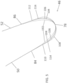
- Fig. 5 illustrates an enlarged radially inward-looking view of the trailing edge portion of the airfoil 36 of Fig. 3 within circle B.
- the enlarged portion of the airfoil trailing edge 46 of Fig. 5 illustrates elliptical contouring of the airfoil 36 at the trailing edge 46, assuming various ellipse a/b ratios.
- Fig. 5 illustrates a first elliptical curvature 102 which tangentially diverges from each of the pressure side 50 and the suction side 52 at the first and second transition points 84, 86.
- the a/b of the first elliptical curvature 102 is 3.0.
- FIG. 5 also illustrates a second elliptical curvature 104 which tangentially diverges from each of the pressure side 50 and the suction side 52 at a third transition point 110 disposed on the pressure side 50 and a fourth transition point 112 disposed on the suction side 52.
- the a/b of the second elliptical curvature 104 is 2.0.
- Fig. 5 also illustrates a third elliptical curvature 106 which tangentially diverges from each of the pressure side 50 and the suction side 52 at a fifth transition point 114 disposed on the pressure side 50 and a sixth transition point 116 disposed on the suction side 52.
- the a/b of the third elliptical curvature 106 is 1.5.
- Fig. 5 also illustrates an airfoil trailing edge 46 with circular curvature 106 which may be considered as the "baseline" configuration.
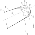
- Fig. 6 illustrates an enlarged radially inward-looking view of the trailing edge portion of the airfoil 36 of Fig. 3 within circle B.
- the enlarged portion of the airfoil trailing edge 46 of Fig. 6 illustrates elliptical contouring only on the suction side 52 of the airfoil 36 at the trailing edge 46, assuming various ellipse a/b ratios.
- a first elliptical curvature 102a with an a/b ratio of 3.0 tapers the suction side 52 from a second transition point 86 to the airfoil trailing edge tip 78.
- Fig. 6 also illustrates the baseline circular curvature 108 at the trailing edge tip 78. For the various elliptical curvatures, as the a/b ratio decreases, the transition point from linear to elliptical moves closer to the trailing edge tip 78.
- Fig. 7 illustrates an enlarged radially inward-looking view of the trailing edge portion of the airfoil 36 of Fig. 3 within circle B.
- the enlarged portion of the airfoil trailing edge 46 of Fig. 7 illustrates elliptical contouring only on the pressure side 50 of the airfoil 36 at the trailing edge 46, assuming various ellipse a/b ratios.
- a first elliptical curvature 102b with an a/b ratio of 3.0 tapers the pressure side 52 from a first transition point 84 to the airfoil trailing edge tip 78.
- a second elliptical curvature 104b with an a/b ratio of 2.0 tapers the pressure side 50 from a third transition point 110 to the airfoil trailing edge tip 78.
- a third elliptical curvature 106b with an a/b ratio of 1.5 tapers the pressure side 50 from a fifth transition point 114 to the airfoil trailing edge tip 78.
- Fig. 7 also illustrates the baseline circular curvature 108 at the trailing edge tip 78. For the various elliptical curvatures, as the a/b ratio decreases, the transition point from linear to elliptical moves closer to the trailing edge tip 78.
- elliptical tapering is disposed only on one side of the airfoil (pressure side 50 or suction side 52).
- pressure side 50 or suction side 52 there may remain an aerodynamic benefit to taper only one of the sides. Due to the magnitude of the aerodynamic benefit of tapering only the pressure side 50 versus tapering only the suction side 52, as well as the ability to provide the required cooling to each of the pressure side 50 and the suction side 52 at the trailing edge 46, it may become apparent that tapering one side provides an advantage over tapering the other side. On the other hand, it may instead be beneficial to taper both sides, but to a lesser degree, for example at a lesser a/b ratio (i.e., instead of tapering only one side at a higher a/b ratio).
- Fig. 8 illustrates an enlarged radially inward-looking view of the trailing edge portion of the airfoil 36 of Fig. 3 within circle B according to an embodiment of the present invention.
- the enlarged portion of the airfoil trailing edge 46 of Fig. 8 illustrates elliptical contouring at the trailing edge 46, assuming various ellipse skew angles.
- the skew angle 126 is defined as an offset between the airfoil camber line 124 and the major axis 58 (not shown) of the ellipse 72 (not shown) that defines the elliptical contouring. (See also Fig. 3 ).
- a first elliptical contouring 118 represents an ellipse 72 that has been rotated at a skew angle of 1 degree, relative to the camber line 124.
- a second elliptical contouring 120 represents an ellipse 72 (not shown) that has been rotated at a skew angle of 3 degrees, relative to the camber line 124.
- a third elliptical contouring 122 represents an ellipse 72 (not shown) that has been rotated at a skew angle of 6 degrees, relative to the camber line 124. All three of the elliptical curvatures illustrated in Fig.
- the third elliptical contouring 122 which is skewed at an angle of 6 degrees relative to the camber line 124, includes a first transition point 84 along the pressure side 50 and a second transition point 86 along the suction side.
- the first transition point 84 is much closer to the trailing edge tip 78, than the second transition point 86. In the embodiment of Fig. 8 , the first transition point 84 is less than half the upstream distance (i.e., relative to the direction of the camber line 124) from the trailing edge tip 78 as is the second transition point 86.
- Each of the first and second transition points 84, 86 represent the transition between the linear and elliptical portions of the airfoil 36 pressure and suction sides 50, 52.
- the baseline circular curvature 108 at the airfoil leading edge 46 is also illustrated in Fig. 8 .
- Fig. 9 illustrates an enlarged radially inward-looking view of the trailing edge portion of the airfoil 36 of Fig. 3 within circle B.
- the enlarged portion of the airfoil trailing edge 46 of Fig. 9 illustrates a hybrid embodiment with elliptical contouring along the pressure side 50 and suction side 52, and circular curvature at the trailing edge tip 78.
- the first elliptical portion 98 on the airfoil pressure side 50 tapers the trailing edge 46 from a first transition point 84 toward the airfoil trailing edge tip 78.
- the second elliptical portion 100 on the airfoil suction side 52 tapers the trailing edge 46 from a second transition point 86 toward the airfoil trailing edge tip 78.
- Each of the first and second transition points 84, 86 represent the transition between the linear and elliptical portions of the airfoil 36 pressure and suction sides 50, 52.
- Each of the first and second elliptical portions 98, 100 correspond to an ellipse 72 (not shown) with an a/b ratio of 3.0.
- the baseline circular curvature 108 at the airfoil leading edge 46 illustrated in Fig. 9 defines a baseline diameter.
- a first tip circle 128 tangentially intersects both the first elliptical portion 98 and the second elliptical portion 100.
- the first tip circle 128 has a diameter that is 80% of the baseline diameter.
- a second tip circle 130 tangentially intersects both the first elliptical portion 98 and the second elliptical portion 100.
- the second tip circle 130 has a diameter that is 60% of the baseline diameter.
- an elliptical tip portion 132 would be truncated and/or removed at the airfoil trailing edge tip 78.
- the first and second tip circles 128, 130 allow for the ease of machining and/or drilling cooling holes as well as other trailing edge features. As the diameter of the first and second tip circles 128, 130 increases, the ease of manufacture may increase, but the efficiency of the airfoil 36 may decrease.
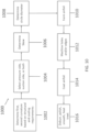
- Fig. 10 illustrates a method 1000 of manufacturing an airfoil 36 according to the embodiments disclosed herein.
- the method includes determining the first and second elliptical curvatures to be used, as well as cooling requirements at the trailing edge 46.
- the method includes selecting the location(s) for applying the contouring and/or elliptical tapering, where the locations may include the airfoil pressure side 50 or the suction side 52 or both.
- the method 100 includes determining what skew angle 126 to use, if any, where a positive skew angle 126 may correspond to biasing the ellipse 72 toward a pressure side 50 and a negative skew angle 126 may correspond to biasing the ellipse 72 toward a suction side 52.
- the method 1000 includes determining the diameter of the tip circle 128, 130 to be used.
- the method 1000 includes forming the airfoil 36. Forming the airfoil 36 may include using investment casting, forging, additive manufacturing, other processes and/or hybrid methods.
- Forming the airfoil 36 may also include forming any elliptical and/or circular contouring at the trailing edge 46 as well as forming any cooling holes, other cooling passages, and/or other trailing edge features. Alternatively forming cooling holes, other cooling features and the elliptical and circular contouring at the trailing edge 46 may be included at step 1012 via post-forming machining processes such as drilling, electrical discharge machining (EDM), laser ablation, milling, as well as other processes.
- EDM electrical discharge machining
- the airfoil 36 may be coated with a coating such as thermal barrier coating (TBC), environmental barrier coating (EBC), bond coats and other types of coatings.
- the method 1000 may include post-processing and/or finishing steps such as deburring, polishing, surface smoothing, sanding, heat treating as well as other processes. Aspects according to the embodiments disclosed herein may omit one of more steps of the method 1000. Similarly, the embodiments disclosed herein of method 1000 may include other steps and may include performing the steps in a different order.
- Fig. 11 illustrates an enlarged radially inward-looking view of the trailing edge portion of the airfoil 36 of Fig. 3 within circle B.
- the enlarged portion of the airfoil trailing edge 46 of Fig. 11 illustrates a hybrid embodiment with elliptical contouring along the pressure side 50 and suction side 52, and circular curvature at the trailing edge tip 78.
- the pressure side 50 transitions from a pressure side linear portion 50a to a first elliptical portion 98 at a first transition point 84.
- the suction side 52 transitions from a suction side linear portion 52a to a second elliptical portion 100 at a second transition point 86.
- the first elliptical portion 98 transitions to a circular tip portion 128 at a first tip transition point 136 while the second elliptical portion 100 transitions to the circular tip portion 128 at a second tip transition point 134.
- each of the first and second transition points are equidistant to the trailing edge 78, which is aligned with a camber line 126 (not shown) since the skew angle is 0 degrees, which does not correspond to the invention as claimed.
- the first and second elliptical portions 98, 100 may be defined by an ellipse 72 (not shown) with an a/b ratio from about 1.1 to about 5.
- the first and second elliptical portions 98, 100 may be defined by an ellipse 72 (not shown) with an a/b ratio from about 1.3 to about 4. In other embodiments, the first and second elliptical portions 98, 100 may be defined by an ellipse 72 (not shown) with an a/b ratio from about 1.5 to about 3.5. In other embodiments, the first and second elliptical portions 98, 100 may be defined by an ellipse 72 (not shown) with an a/b ratio from about 2.0 to about 3.0.
- first and second elliptical portions 98, 100 may be defined by an ellipse 72 with a/b ratios in other ranges and subranges as those mentioned above, including embodiments in which the first elliptical portion 98 is defined by an ellipse with a different a/b ratio than that of the second elliptical portion 100.
- the trailing edge portion 46 may also include at least one coating 138 (TBC, EBC, bond coat, etc) disposed on the first and second elliptical portions 98, 100, on the circular tip portion 128, as well as elsewhere on the airfoil 36.
- a thickness of the coating 138 may vary to form the curvature of the first and/or second elliptical portions 98, 100 as well as the curvature of the circular tip portion 128.
- the coating 138 disposed on the airfoil 36 may increase or decrease in thickness as the leading edge portion 46 transitions from the pressure side and suction side linear portions 50a, 52a to the first and second elliptical portions 98, 100 to the circular tip portion 128.
- the metallic and/or superalloy material with which the airfoil 36 may be formed may similarly be contoured in concert with the thickness of the coating 138 such that the profile of the finished airfoil 36, which includes both the material with which the airfoil 36 was formed as well as any coating 138 disposed thereon, transitions from linear portions to one or more elliptical portions to at least one circular portion at the trailing edge tip 78. Stated otherwise, the aerodynamic benefits discussed herein are based on the outermost surfaces and profile of the airfoil 36, regardless of whether the outermost surfaces include the material from which the airfoil 36 is formed or coating 138 disposed thereon.
- the desired airfoil profile may be beneficial to form the desired airfoil profile by varying the thickness of the coating 138 as the airfoil 36 transitions from the pressure side and suction side linear portions 50a, 52a to the first and second elliptical portions 98, 100 to the circular tip portion 128.
- the airfoil 36 may also be formed in the geometries and/or shapes described herein from ceramic and/or ceramic matrix composite (CMC) materials, and may be coated or uncoated. CMC airfoils 36, shaped according to the present embodiments, would have similar aerodynamic benefits to similarly shaped metallic airfoils.
- the embodiments disclosed herein may include circular tip portions 128 that have a diameter that is about 5%, 10%, 20%, 40%, 60%, 80%, 90%, and 95%, as well as other percentages of the diameter of the baseline circular tip 108 shown in Figures 5-9 .
- the present embodiments may include circular tip portions 128 that have a diameter that is between about 55% and about 85% of the baseline circular tip 108.
- the embodiments disclosed herein may include circular tip portions 128 that have a diameter that is between about 60% and about 80% of the baseline circular tip 108.
- the embodiments disclosed herein may include circular tip portions 128 that have a diameter that is between about 60% and about 95% of the baseline circular tip 108.
- the invention includes other than 0 degrees skew angles from about -10 degrees to about 10 degrees, from about -8 degrees to about 8 degrees, from about -6 degrees to about 6 degrees, from about -4 degrees to about 4 degrees, from about -3 degrees to about 3 degrees, from about -1 degree to about 1 degree, and in other ranges and subranges, where a positive skew angle biases the elliptical tapering toward the pressure side 50 and a negative skew angle biases the elliptical tapering toward the suction side 52.
- the invention includes other than 0 degrees skew angles from about -6 degrees to about -3 degrees or from about 3 degrees to about 6 degrees, or from about 1 degree to about 8 degrees or from about -8 degrees to about -1 degrees.
- the embodiments disclosed herein may include elliptical tapering along both a pressure side 50 and a suction side 52 in equal amounts, along only a suction side 52, along only a pressure side 50, and along both a pressure side 50 and a suction side 52 in different amounts.
- the embodiments presented herein produce a smaller, lower-loss wake by locally decreasing the blockage at the trailing edge 46 of the airfoil 36 without substantially impacting the upstream airfoil thickness or the ability to drill trailing edge 46 cooling holes.
- a nominal circular trailing edge is replaced by an elliptical transition that blends the original airfoil surface to a smaller trailing edge circle.
- Employing a hybrid trialing edge including elliptical transitions at the pressure and suction sides 50, 52 along with a circular tip may improve the profile loss via smaller effective trailing edge blockage and improved airfoil base pressure.
- a smaller wake produced by the trailing edge of the embodiments disclosed herein also benefits downstream airfoils via reduced unsteady loss.
- the impact to airfoil thickness where internal cavities and cooling features reside is minimally impacted. Blending the ellipse back to a circular end minimizes discharge hole drilling concerns. Benefits of the embodiments disclosed herein may also include a reduced aerodynamic loss with minimal impact to mechanical design versus a traditional airfoil designed to the same final trailing edge circle diameter.
- All cooled airfoils are expected to benefit from the application of this hybrid elliptical-circular approach.
- unsteady losses in downstream airfoils may also improve due to the smaller velocity defect (wake) produced by the hybrid elliptical-circular trailing edge.
- Linear tapering, piecewise linear tapering (i.e., multiple linear segments), hyperbolic tapering, quadratic tapering, and/or other forms of geometric tapering at the trailing edge 46 may also improve the airfoil aerodynamics via reduced profile loss et al.
- elliptical tapering represents an enhanced gradual transition for increasing the curvature of the airfoil 36 from the linear portions at the pressure side and suction side 50, 52 moving toward the trailing edge tip 78.
Description
- The invention relates to turbine airfoils and more specifically to airfoil trailing edges.
- Airfoils of finite thickness produce a wake. The loss associated with this wake is proportional to the trailing edge diameter. While designing to a thinner trailing edge diameter is aerodynamically desirable, the presence of internal cooling flow cavities and trailing edge cooling holes limit the reduction in thickness that can be practically achieved. Flow attachment, the finite thickness of the airfoil trailing edge, combined with the boundary layers that form on the suction and pressure surfaces of the airfoil, form a wake region characterized by a velocity deficit and loss generation. As the width of this defect region increases, the total loss of the airfoil increases. Cooled turbine airfoils require internal chambers to supply cooling flow to various locations along the airfoil. As part of a typical cooling scheme, holes are drilled through the end of the trailing edge to the internal chamber to provide local cooling to the trailing edge. The desire to locate the internal chamber near the trailing edge, and the diameter of the trailing edge holes, are important factors that lead to large trailing edge diameters for cooled airfoils, and hence wide, high-loss wakes.
- In order to minimize loss, small trailing edge diameter may be employed. Using a traditionally designed circular trailing edge, reducing the trailing edge diameter significantly reduces the airfoil thickness far upstream of the trailing edge, which may impact the ability to design the cooling system, as internal Mach numbers for the cooling flow increases (lowering effectiveness), and the distance of the internal chamber to the trailing edge increases.
-
DE 10 2016 222789 A1 ,US 2015/233253 A1 ,EP 3 231 996 A1 , andWO 2010/057627 A1 each disclose an airfoil of a compressor blade or a turbine blade comprising an airfoil body including a trailing edge having the features of the preamble ofindependent claim 1.US 2017/370222 A1 discloses a method of manufacturing an airfoil and forming ejection slots in the airfoil trailing edge. - In accordance with an aspect of the invention an airfoil includes:
an airfoil body extending from a radially inner root portion to a radially outer tip portion, extending from a pressure side to a suction side, and from a leading edge to a trailing edge portion; wherein the trailing edge portion includes: a linear pressure side portion; a linear suction side portion; a trailing edge tip portion; and at least one elliptical portion disposed between the trailing edge tip portion and at least one of the linear pressure side portion and the linear suction side portion. The trailing edge tip portion comprises a circular trailing edge tip portion disposed directly downstream of the at least one elliptical portion and defined by a circle that tangentially overlaps with the at least one elliptical portion in the vicinity of the trailing edge tip. The at least one elliptical portion is defined by an ellipse having a skew angle between -10 degrees and 10 degrees and other than 0 degrees, wherein the skew angle is the angle between a major axis (a) of the ellipse (72) and a camber line (124) of the airfoil. - In accordance with another aspect of the invention a method of forming an airfoil includes: determining an elliptical curvature of at least one elliptical portion of an airfoil trailing edge, the at least one elliptical portion disposed between a trailing edge tip portion and at least one of a linear pressure side portion along an airfoil pressure side (50) and a linear suction side portion of an airfoil suction side, wherein the elliptical curvature is defined by an ellipse having an a/b ratio between about 1.1 and about 5.0, where "a" is representative of a length of a major axis of the ellipse, and where "b" is representative of a length of a minor axis of the ellipse; determing a skew angle of the elliptical portion, wherein the skew angle is defined as the angle between the major axis of the ellipse and a camber line of the airfoil, wherein the skew angle is between -10 degrees and 10 degrees and other than 0 degrees; determining a diameter of a circular trailing edge tip portion of the trailing edge tip portion, the circular trailing edge tip portion disposed directly downstream of the at least one elliptical portion and defined by a circle that tangentially overlaps with the at least one elliptical portion in the vicinity of the trailing edge tip; and forming the airfoil.
- In accordance with another aspect of the embodiments disclosed herein, a gas turbine engine includes: a compressor section; a combustor section; and a turbine section, wherein the turbine section includes at least one airfoil, the at least one airfoil being configured as described above.
- These and other features, aspects, and advantages of the embodiments disclosed herein will become better understood when the following detailed description is read with reference to the accompanying drawings in which like characters represent like parts throughout the drawings, wherein:
-
FIG. 1 is a schematic representation of a gas turbine engine in an industrial application; -
FIG. 2 is a side view of a turbine airfoil; -
FIG. 3 is top radially inward-looking view of a turbine airfoil; -
Fig. 4 is an enlarged radially inward-looking view of the trailing edge portion of the airfoil; -
FIG. 5 is an enlarged radially inward-looking view of the trailing edge portion of the airfoil; -
FIG. 6 is an enlarged radially inward-looking view of the trailing edge portion of the airfoil; -
Fig. 7 is an enlarged radially inward-looking view of the trailing edge portion of the airfoil; -
Fig. 8 is an enlarged radially inward-looking view of the trailing edge portion of the airfoil; -
Fig. 9 is an enlarged radially inward-looking view of the trailing edge portion of the airfoil; -
Fig. 10 illustrates a method of forming an airfoil; and -
Fig. 11 is an enlarged radially inward-looking view of the trailing edge portion of the airfoil, the trailing edge portion as such being not configured according to the invention as claimed. - Unless otherwise indicated, the drawings provided herein are meant to illustrate features of embodiments of the disclosure. These features are believed to be applicable in a wide variety of systems comprising one or more embodiments of the disclosure. As such, the drawings are not meant to include all conventional features known by those of ordinary skill in the art to be required for the practice of the embodiments disclosed herein.
- In the following specification and the claims, reference will be made to a number of terms, which shall be defined to have the following meanings.
- The singular forms "a", "an", and "the" include plural references unless the context clearly dictates otherwise.
- "Optional" or "optionally" means that the subsequently described event or circumstance may or may not occur, and that the description includes instances where the event occurs and instances where it does not.
- Approximating language, as used herein throughout the specification and claims, may be applied to modify any quantitative representation that could permissibly vary without resulting in a change in the basic function to which it is related. Accordingly, a value modified by a term or terms, such as "about" and "substantially", are not to be limited to the precise value specified. In at least some instances, the approximating language may correspond to the precision of an instrument for measuring the value. Here and throughout the specification and claims, range limitations may be combined and/or interchanged, such ranges are identified and include all the sub-ranges contained therein unless context or language indicates otherwise.
- As used herein, the term "axial" refers to a direction aligned with a central axis or shaft of the gas turbine engine or alternatively the central axis of a propulsion engine and/or internal combustion engine. An axially forward end of the gas turbine engine is the end proximate the fan and/or compressor inlet where air enters the gas turbine engine. An axially aft end of the gas turbine engine is the end of the gas turbine proximate the engine exhaust where low pressure combustion gases exit the engine via the low pressure (LP) turbine. In non-turbine engines, axially aft is toward the exhaust and axially forward is toward the inlet.
- As used herein, the term "circumferential" refers to a direction or directions around (and tangential to) the circumference of an annulus of a combustor, or for example the circle defined by the swept area of the turbine blades. As used herein, the terms "circumferential" and "tangential" are synonymous.
- As used herein, the term "radial" refers to a direction moving outwardly away from the central axis of the gas turbine, or alternatively the central axis of a propulsion engine. A "radially inward" direction is aligned toward the central axis moving toward decreasing radii. A "radially outward" direction is aligned away from the central axis moving toward increasing radii.
- Referring now to the drawings, wherein like numerals refer to like components,
Fig. 1 illustrates an example of agas turbine 10 which may incorporate various aspects of the embodiments disclosed herein. As shown, thegas turbine 10 generally includes acompressor section 12 having aninlet 14 disposed at an upstream end of thegas turbine 10, and acasing 16 that at least partially surrounds thecompressor section 12. Thegas turbine 10 further includes acombustion section 18 having at least onecombustor 20 downstream from thecompressor section 12, and aturbine section 22 downstream from thecombustion section 18. As shown, thecombustion section 18 may include a plurality of thecombustors 20. Ashaft 24 extends axially through thegas turbine 10.Fig. 1 illustrates the radial 94, axial 92 andcircumferential directions 90. - In operation,
air 26 is drawn into theinlet 14 of thecompressor section 12 and is progressively compressed to providecompressed air 28 to thecombustion section 18. The compressedair 28 flows into thecombustion section 18 and is mixed with fuel in thecombustor 20 to form a combustible mixture. The combustible mixture is burned in thecombustor 20, thereby generating ahot gas 30 that flows from thecombustor 20 across afirst stage 32 ofturbine nozzles 34 and into theturbine section 22. The turbine section generally includes one or more rows ofrotor blades 36 axially separated by an adjacent row of theturbine nozzles 34. Therotor blades 36 are coupled to therotor shaft 24 via a rotor disk. Therotor shaft 24 rotates about an engine centerline CL. Aturbine casing 38 at least partially encases therotor blades 36 and theturbine nozzles 34. Each or some of the rows ofrotor blades 36 may be concentrically surrounded by ashroud block assembly 40 that is disposed within theturbine casing 38. Thehot gas 30 rapidly expands as it flows through theturbine section 22. Thermal and/or kinetic energy is transferred from thehot gas 30 to each stage of therotor blades 36, thereby causing theshaft 24 to rotate and produce mechanical work. Theshaft 24 may be coupled to a load such as a generator (not shown) so as to produce electricity. In addition, or in the alternative, theshaft 24 may be used to drive thecompressor section 12 of the gas turbine. -
Fig. 2 provides an enlarged cross section side view of an exemplary turbine rotor blade orairfoil 36, which extends from an axially forward leading edge 44 to an axiallyaft trailing edge 46 and from a radiallyinward root 48 to a radially outer tip 42. Theairfoil 36 includes aplatform 50 defining a radially inner boundary of a hot gas path. - Airfoils composed of superalloy materials such as nickel-based superalloys and other metallic superalloys may be formed using investment casting, additive manufacturing and other techniques, which produces the desired material properties for operation within a
turbine section 22 of agas turbine engine 10. However, even with superalloy materials, turbine airfoils often still need to be cooled. Internal air-cooled passageways are often formed with airfoils to provide sufficient cooling to the airfoil. For example, internal cooling channels and flow circuits of anairfoil 36 may be formed using investment casting, additive manufacturing and/or via machining processes such as electrical discharge machining (EDM). -
Fig. 3 illustrates a top (radially inward looking) view of a cross-section ofairfoil 36 taken along line A-A shown inFig. 2 . The airfoil extends from a leading edge 44 to a trailingedge 46 and from apressures side 50 to asuction side 52 and may include at least onecentral cavity 64 extending radially through the airfoil body portion 37. A leadingedge feed cavity 62 extends radially through theairfoil 36 and receives cooling air from the airfoil root portion 48 (not shown). Cooling air travels through at least onecross-over hole 66 from the leadingedge feed cavity 62 into a leadingedge shower head 68 which distributes cooling air to the exterior of theairfoil 36 at the leading edge 44 via a plurality of cooling passages (not shown). Theairfoil 36 also includes at least one trailingedge feed cavity 70. The airfoil may also include a plurality of large perimeter radial cooling passages 54 aligned along thesuction side 52 of theairfoil 36, as well as a plurality of smaller perimeterradial cooling passages 56 aligned along thepressure side 50 of theairfoil 36. The airfoil may also include other numbers of cooling passages and arrangements including cooling passages with cross sections of different shapes and aligned in different orientations including axially and circumferentially. Theairfoil 36 may also include other airfoil cooling, thermal management and/or structural architectures than those shown inFig. 3 . Film cooling holes (not shown) are often placed around the outer periphery of the airfoil. For example, film cooling holes (not shown) are often placed along the leading edge, the trailing edge, the suction side and the pressure side. Cooling air flows through film cooling holes (not shown) from one or moreinternal airfoil passages airfoil 36. -
Fig. 4 illustrates an enlarged radially inward-looking view of the trailing edge portion of theairfoil 36 ofFig. 3 within circle B. The enlarged portion of theairfoil trailing edge 46 ofFig. 4 illustrates theairfoil pressure side 50 and thesuction side 52. Thepressure side 50 andsuction side 52 approach the trailingedge 46, and gradually converge towards each other. Each of thepressure side 50 andsuction side 52 include linear portions (50a and 52a respectively) which are substantially linear with zero or near-zero curvature, as they approach the trailingedge 46. The near-zero curvature of the linear or substantially linear pressure sidelinear portion 50a and suction side linear portion 52a is defined by the airfoil design and may vary from one airfoil design to the next. With conventional airfoils, each of thepressure side 50 andsuction side 52 transition to anominal semicircle 80 at first and secondnominal transitions diameter 76, extending across thenominal semicircle 80, and extending from thepressure side 50 to thesuction side 52. With conventional airfoils, the linear portions of thepressure side 50 andsuction side 52 transition directly to thenominal semicircle 80 at first and secondnominal transitions - Referring still to
Fig. 4 , theairfoil 36 of the embodiments disclosed herein includes an elliptical transition from the linear portions of thepressure side 50 andsuction side 52 to a trailingedge tip 78. A firstelliptical portion 98 extends from afirst transition point 84 on thepressure side 50 to thetip 78 of the trailingedge 46. A secondelliptical portion 100 extends from asecond transition point 86 on thesuction side 52 to thetip 78 of the trailingedge 46. The first andsecond transition points suction side elliptical portions elliptical portions ellipse 72, which itself is defined by amajor axis 58, and aminor axis 60. Themajor axis 58 may also be represented by the variable "a" while the minor axis may also be represented by the variable "b." The "pointiness" or elongation of theellipse 72 can be characterized using the ratio of the length of themajor axis 58 divided by the length of theminor axis 60, which is also known as the a/b ratio. Themajor axis 58 may be oriented at afirst angle 62 which is defined in terms of theaxial direction 92 such that themajor axis 58 of theellipse 72 is aligned with a camber line of the airfoil 36 (and thus does not conform to the invention as claimed), where the camber line is the mid-point between theairfoil pressure side 50 and theairfoil suction side 52 at any point between the leading edge 44 (not shown) and the trailingedge 46. Stated otherwise, the camber line of the airfoil may be defined as the set of points that are equidistant between thepressure side 50 and thesuction side 52. Each of the first andsecond transition points edge tip 78 than) the first and secondnominal transitions - Still referring to
Fig. 4 , theairfoil 36 includes a circular trailing edge portion defined by acircle 82 that tangentially overlaps with each of the first and secondelliptical portions edge tip 78. Thecircle 82 may have acircle diameter 74 that is less than thesemicircular diameter 76 of the nominal trailing edge. Thecircle 82 defines the curvature of the trailingedge 46 at the trailingedge tip 78. Stated otherwise, the curvature of theairfoil 36 at the trailingedge tip 78 is circular rather than elliptical, causing the trailingedge tip 78 to be more rounded than it would have been with an elliptical curvature. The elliptical contouring of theairfoil 36 along thepressure side 50 andsuction side 52 approaching the trailingedge 46 reduces the trailing edge pressure losses resulting in more efficient flow past theairfoil 36 which in turn increases the turbine efficiency. Stated otherwise, elliptically tapering theairfoil 36 along thepressure side 50 andsuction side 52 approaching the trailingedge 46 results in a "thinning" of the airfoil which in turn makes the airfoil more aerodynamic. The circular curvature at the trailingedge tip 78, makes it easier to perform machining operations such as drilling (i.e., via electrical discharge machining (EDM), for example) trailing edge cooling holes for two reasons. Firstly, a circle has constant curvature resulting in drilling operations that may be controlled precisely regardless of where along the circular curvature the drilling operations occur (as compared to an ellipse, which has constantly varying curvature). Secondly, the overall curvature of the trailingedge 46 at thetip 78 may be reduced with a circular shape versus an elliptical one, again resulting in simplified machining. -
Fig. 5 illustrates an enlarged radially inward-looking view of the trailing edge portion of theairfoil 36 ofFig. 3 within circle B. The enlarged portion of theairfoil trailing edge 46 ofFig. 5 illustrates elliptical contouring of theairfoil 36 at the trailingedge 46, assuming various ellipse a/b ratios.Fig. 5 illustrates a firstelliptical curvature 102 which tangentially diverges from each of thepressure side 50 and thesuction side 52 at the first andsecond transition points elliptical curvature 102 is 3.0.Fig. 5 also illustrates a secondelliptical curvature 104 which tangentially diverges from each of thepressure side 50 and thesuction side 52 at athird transition point 110 disposed on thepressure side 50 and afourth transition point 112 disposed on thesuction side 52. The a/b of the secondelliptical curvature 104 is 2.0.Fig. 5 also illustrates a thirdelliptical curvature 106 which tangentially diverges from each of thepressure side 50 and thesuction side 52 at afifth transition point 114 disposed on thepressure side 50 and asixth transition point 116 disposed on thesuction side 52. The a/b of the thirdelliptical curvature 106 is 1.5.Fig. 5 also illustrates anairfoil trailing edge 46 withcircular curvature 106 which may be considered as the "baseline" configuration. - Still referring to
Fig. 5 , as the a/b ratio of thecurvature trailing edge 46 increases, the transition point moves further away from the trailingedge tip 78. Stated otherwise, with higher a/b ratios, the elliptical tapering of theairfoil 36 at the trailingedge 46 occurs earlier and further away from the trailingedge tip 78, resulting in anarrower airfoil 36 at the trailingedge 46. The narrower the trailingedge 46, the more aerodynamic the airfoil 36 (i.e., the trailing edge losses are lower). However, with airfoils that are narrower at the trailingedge 46, mechanical stresses may increase. In addition, there is less area and/or volume available for disposing cooling channels, holes and passageways therebetween. Furthermore, due to limits in manufacturing processes associated with the size various cooling features can be made within acceptable repeatability and tolerance requirements, the cooling features cannot necessarily be simply scaled down to smaller sizes to accommodate anarrower trailing edge 46. Therefore, due to manufacturing, cooling and/or stress-related constraints, there is likely an upper limit to the a/b ratio that can be employed, even though the higher a/b ratio designs may yield higher efficiency turbine airfoils. -
Fig. 6 illustrates an enlarged radially inward-looking view of the trailing edge portion of theairfoil 36 ofFig. 3 within circle B. The enlarged portion of theairfoil trailing edge 46 ofFig. 6 illustrates elliptical contouring only on thesuction side 52 of theairfoil 36 at the trailingedge 46, assuming various ellipse a/b ratios. A first elliptical curvature 102a with an a/b ratio of 3.0 tapers thesuction side 52 from asecond transition point 86 to the airfoil trailingedge tip 78. A second elliptical curvature 104a with an a/b ratio of 2.0 tapers thesuction side 52 from afourth transition point 112 to the airfoil trailingedge tip 78. A third elliptical curvature 106a with an a/b ratio of 1.5 tapers thesuction side 52 from asixth transition point 116 to the airfoil trailingedge tip 78.Fig. 6 also illustrates the baselinecircular curvature 108 at the trailingedge tip 78. For the various elliptical curvatures, as the a/b ratio decreases, the transition point from linear to elliptical moves closer to the trailingedge tip 78. -
Fig. 7 illustrates an enlarged radially inward-looking view of the trailing edge portion of theairfoil 36 ofFig. 3 within circle B. The enlarged portion of theairfoil trailing edge 46 ofFig. 7 illustrates elliptical contouring only on thepressure side 50 of theairfoil 36 at the trailingedge 46, assuming various ellipse a/b ratios. A firstelliptical curvature 102b with an a/b ratio of 3.0 tapers thepressure side 52 from afirst transition point 84 to the airfoil trailingedge tip 78. A secondelliptical curvature 104b with an a/b ratio of 2.0 tapers thepressure side 50 from athird transition point 110 to the airfoil trailingedge tip 78. A thirdelliptical curvature 106b with an a/b ratio of 1.5 tapers thepressure side 50 from afifth transition point 114 to the airfoil trailingedge tip 78.Fig. 7 also illustrates the baselinecircular curvature 108 at the trailingedge tip 78. For the various elliptical curvatures, as the a/b ratio decreases, the transition point from linear to elliptical moves closer to the trailingedge tip 78. For each of the embodiments ofFigures 6 and 7 , elliptical tapering is disposed only on one side of the airfoil (pressure side 50 or suction side 52). With airfoil designs in which there is not enough space to taper both thepressure side 50 and thesuction side 52, there may remain an aerodynamic benefit to taper only one of the sides. Due to the magnitude of the aerodynamic benefit of tapering only thepressure side 50 versus tapering only thesuction side 52, as well as the ability to provide the required cooling to each of thepressure side 50 and thesuction side 52 at the trailingedge 46, it may become apparent that tapering one side provides an advantage over tapering the other side. On the other hand, it may instead be beneficial to taper both sides, but to a lesser degree, for example at a lesser a/b ratio (i.e., instead of tapering only one side at a higher a/b ratio). -
Fig. 8 illustrates an enlarged radially inward-looking view of the trailing edge portion of theairfoil 36 ofFig. 3 within circle B according to an embodiment of the present invention. The enlarged portion of theairfoil trailing edge 46 ofFig. 8 illustrates elliptical contouring at the trailingedge 46, assuming various ellipse skew angles. Theskew angle 126 is defined as an offset between theairfoil camber line 124 and the major axis 58 (not shown) of the ellipse 72 (not shown) that defines the elliptical contouring. (See alsoFig. 3 ). Each of the elliptical contourings illustrated inFig. 8 have been rotated or tilted toward theairfoil pressure side 50 at acertain skew angle 126. A firstelliptical contouring 118 represents anellipse 72 that has been rotated at a skew angle of 1 degree, relative to thecamber line 124. A secondelliptical contouring 120 represents an ellipse 72 (not shown) that has been rotated at a skew angle of 3 degrees, relative to thecamber line 124. A thirdelliptical contouring 122 represents an ellipse 72 (not shown) that has been rotated at a skew angle of 6 degrees, relative to thecamber line 124. All three of the elliptical curvatures illustrated inFig. 8 correspond to an a/b ration of 3.0. Skewing theellipse 72 relative to thecamber line 124 may be beneficial when biasing the elliptical contouring toward thepressure side 50 or thesuction side 52 is desired. When faced with being able to contour only thepressure side 50 or the suction side 52 (due to cooling, mechanical stress, aerodynamic, and other factors) using a skewed approach may also be considered as a viable alternative option. As illustrated inFig. 8 , the thirdelliptical contouring 122, which is skewed at an angle of 6 degrees relative to thecamber line 124, includes afirst transition point 84 along thepressure side 50 and asecond transition point 86 along the suction side. Because of the 6-degree skew angle 126 toward the pressure side, thefirst transition point 84 is much closer to the trailingedge tip 78, than thesecond transition point 86. In the embodiment ofFig. 8 , thefirst transition point 84 is less than half the upstream distance (i.e., relative to the direction of the camber line 124) from the trailingedge tip 78 as is thesecond transition point 86. Each of the first andsecond transition points airfoil 36 pressure andsuction sides circular curvature 108 at theairfoil leading edge 46 is also illustrated inFig. 8 . -
Fig. 9 illustrates an enlarged radially inward-looking view of the trailing edge portion of theairfoil 36 ofFig. 3 within circle B. The enlarged portion of theairfoil trailing edge 46 ofFig. 9 illustrates a hybrid embodiment with elliptical contouring along thepressure side 50 andsuction side 52, and circular curvature at the trailingedge tip 78. As illustrated inFig. 9 , the firstelliptical portion 98 on theairfoil pressure side 50 tapers the trailingedge 46 from afirst transition point 84 toward the airfoil trailingedge tip 78. The secondelliptical portion 100 on theairfoil suction side 52 tapers the trailingedge 46 from asecond transition point 86 toward the airfoil trailingedge tip 78. Each of the first andsecond transition points airfoil 36 pressure andsuction sides elliptical portions circular curvature 108 at theairfoil leading edge 46 illustrated inFig. 9 defines a baseline diameter. Afirst tip circle 128 tangentially intersects both the firstelliptical portion 98 and the secondelliptical portion 100. Thefirst tip circle 128 has a diameter that is 80% of the baseline diameter. Asecond tip circle 130 tangentially intersects both the firstelliptical portion 98 and the secondelliptical portion 100. Thesecond tip circle 130 has a diameter that is 60% of the baseline diameter. By employing one of the first and second tip circles 128, 130, anelliptical tip portion 132 would be truncated and/or removed at the airfoil trailingedge tip 78. As discussed above, the first and second tip circles 128, 130 allow for the ease of machining and/or drilling cooling holes as well as other trailing edge features. As the diameter of the first and second tip circles 128, 130 increases, the ease of manufacture may increase, but the efficiency of theairfoil 36 may decrease. Thus, it is advantageous to select a tip circle diameter corresponding to the smallest diameter that still allows acceptable manufacturability. Accordingly, it may be possible to achieve both larger a/b ratios and smaller tip circle diameters with larger airfoils as compared to smaller airfoils. -
Fig. 10 illustrates amethod 1000 of manufacturing anairfoil 36 according to the embodiments disclosed herein. Atstep 1002, the method includes determining the first and second elliptical curvatures to be used, as well as cooling requirements at the trailingedge 46. Atstep 1004, the method includes selecting the location(s) for applying the contouring and/or elliptical tapering, where the locations may include theairfoil pressure side 50 or thesuction side 52 or both. Atstep 1006, themethod 100 includes determining whatskew angle 126 to use, if any, where apositive skew angle 126 may correspond to biasing theellipse 72 toward apressure side 50 and anegative skew angle 126 may correspond to biasing theellipse 72 toward asuction side 52. Atstep 1008, themethod 1000 includes determining the diameter of thetip circle method 1000 includes forming theairfoil 36. Forming theairfoil 36 may include using investment casting, forging, additive manufacturing, other processes and/or hybrid methods. Forming theairfoil 36 may also include forming any elliptical and/or circular contouring at the trailingedge 46 as well as forming any cooling holes, other cooling passages, and/or other trailing edge features. Alternatively forming cooling holes, other cooling features and the elliptical and circular contouring at the trailingedge 46 may be included atstep 1012 via post-forming machining processes such as drilling, electrical discharge machining (EDM), laser ablation, milling, as well as other processes. Atstep 1014, theairfoil 36 may be coated with a coating such as thermal barrier coating (TBC), environmental barrier coating (EBC), bond coats and other types of coatings. Atstep 1016, themethod 1000 may include post-processing and/or finishing steps such as deburring, polishing, surface smoothing, sanding, heat treating as well as other processes. Aspects according to the embodiments disclosed herein may omit one of more steps of themethod 1000. Similarly, the embodiments disclosed herein ofmethod 1000 may include other steps and may include performing the steps in a different order. -
Fig. 11 illustrates an enlarged radially inward-looking view of the trailing edge portion of theairfoil 36 ofFig. 3 within circle B. The enlarged portion of theairfoil trailing edge 46 ofFig. 11 illustrates a hybrid embodiment with elliptical contouring along thepressure side 50 andsuction side 52, and circular curvature at the trailingedge tip 78. As illustrated inFig. 11 , thepressure side 50 transitions from a pressure sidelinear portion 50a to a firstelliptical portion 98 at afirst transition point 84. Thesuction side 52 transitions from a suction side linear portion 52a to a secondelliptical portion 100 at asecond transition point 86. The firstelliptical portion 98 transitions to acircular tip portion 128 at a firsttip transition point 136 while the secondelliptical portion 100 transitions to thecircular tip portion 128 at a secondtip transition point 134. In the embodiment ofFig. 11 , each of the first and second transition points are equidistant to the trailingedge 78, which is aligned with a camber line 126 (not shown) since the skew angle is 0 degrees, which does not correspond to the invention as claimed. The first and secondelliptical portions elliptical portions elliptical portions elliptical portions elliptical portions ellipse 72 with a/b ratios in other ranges and subranges as those mentioned above, including embodiments in which the firstelliptical portion 98 is defined by an ellipse with a different a/b ratio than that of the secondelliptical portion 100. - Referring still to
Fig. 11 , the trailingedge portion 46 may also include at least one coating 138 (TBC, EBC, bond coat, etc) disposed on the first and secondelliptical portions circular tip portion 128, as well as elsewhere on theairfoil 36. A thickness of thecoating 138 may vary to form the curvature of the first and/or secondelliptical portions circular tip portion 128. For example, thecoating 138 disposed on theairfoil 36 may increase or decrease in thickness as theleading edge portion 46 transitions from the pressure side and suction sidelinear portions 50a, 52a to the first and secondelliptical portions circular tip portion 128. The metallic and/or superalloy material with which theairfoil 36 may be formed may similarly be contoured in concert with the thickness of thecoating 138 such that the profile of thefinished airfoil 36, which includes both the material with which theairfoil 36 was formed as well as anycoating 138 disposed thereon, transitions from linear portions to one or more elliptical portions to at least one circular portion at the trailingedge tip 78. Stated otherwise, the aerodynamic benefits discussed herein are based on the outermost surfaces and profile of theairfoil 36, regardless of whether the outermost surfaces include the material from which theairfoil 36 is formed orcoating 138 disposed thereon. As such, in some embodiments, it may be beneficial to form the desired airfoil profile by varying the thickness of thecoating 138 as theairfoil 36 transitions from the pressure side and suction sidelinear portions 50a, 52a to the first and secondelliptical portions circular tip portion 128. Theairfoil 36 may also be formed in the geometries and/or shapes described herein from ceramic and/or ceramic matrix composite (CMC) materials, and may be coated or uncoated. CMC airfoils 36, shaped according to the present embodiments, would have similar aerodynamic benefits to similarly shaped metallic airfoils. - The embodiments disclosed herein may include
circular tip portions 128 that have a diameter that is about 5%, 10%, 20%, 40%, 60%, 80%, 90%, and 95%, as well as other percentages of the diameter of the baselinecircular tip 108 shown inFigures 5-9 . For example, the present embodiments may includecircular tip portions 128 that have a diameter that is between about 55% and about 85% of the baselinecircular tip 108. Similarly, the embodiments disclosed herein may includecircular tip portions 128 that have a diameter that is between about 60% and about 80% of the baselinecircular tip 108. Similarly, the embodiments disclosed herein may includecircular tip portions 128 that have a diameter that is between about 60% and about 95% of the baselinecircular tip 108. The invention includes other than 0 degrees skew angles from about -10 degrees to about 10 degrees, from about -8 degrees to about 8 degrees, from about -6 degrees to about 6 degrees, from about -4 degrees to about 4 degrees, from about -3 degrees to about 3 degrees, from about -1 degree to about 1 degree, and in other ranges and subranges, where a positive skew angle biases the elliptical tapering toward thepressure side 50 and a negative skew angle biases the elliptical tapering toward thesuction side 52. For example, the invention includes other than 0 degrees skew angles from about -6 degrees to about -3 degrees or from about 3 degrees to about 6 degrees, or from about 1 degree to about 8 degrees or from about -8 degrees to about -1 degrees. The embodiments disclosed herein may include elliptical tapering along both apressure side 50 and asuction side 52 in equal amounts, along only asuction side 52, along only apressure side 50, and along both apressure side 50 and asuction side 52 in different amounts. - The embodiments presented herein produce a smaller, lower-loss wake by locally decreasing the blockage at the trailing
edge 46 of theairfoil 36 without substantially impacting the upstream airfoil thickness or the ability to drill trailingedge 46 cooling holes. A nominal circular trailing edge is replaced by an elliptical transition that blends the original airfoil surface to a smaller trailing edge circle. Employing a hybrid trialing edge including elliptical transitions at the pressure andsuction sides - All cooled airfoils, particularly those that implement trailing edge discharge cooling flow, are expected to benefit from the application of this hybrid elliptical-circular approach. In addition to reducing the profile loss of the airfoil to which the new trailing edge is applied, unsteady losses in downstream airfoils may also improve due to the smaller velocity defect (wake) produced by the hybrid elliptical-circular trailing edge. Linear tapering, piecewise linear tapering (i.e., multiple linear segments), hyperbolic tapering, quadratic tapering, and/or other forms of geometric tapering at the trailing
edge 46 may also improve the airfoil aerodynamics via reduced profile loss et al. However, elliptical tapering represents an enhanced gradual transition for increasing the curvature of theairfoil 36 from the linear portions at the pressure side andsuction side edge tip 78. - While only certain features of the invention have been illustrated and described herein, many modifications and changes will occur to those skilled in the art. It is, therefore, to be understood that the appended claims are intended to cover all such modifications and changes as fall within the true spirit of the invention.
- This written description uses examples to disclose the embodiments disclosed herein, including the best mode, and also to enable any person skilled in the art to practice the embodiments disclosed herein, including making and using any devices or systems and performing any incorporated methods. The patentable scope of the disclosure is defined by the claims, and may include other examples that occur to those skilled in the art. Such other examples are intended to be within the scope of the claims if they include structural elements that do not differ from the literal language of the claims, or if they include equivalent structural elements with insubstantial differences from the literal languages of the claims.
Claims (14)
- An airfoil comprising:an airfoil body (36) extending from a radially inner root portion (48) to a radially outer tip portion (42), the airfoil body (36) extending from a pressure side (50) to a suction side (52), the airfoil body (36) extending from a leading edge (44) to a trailing edge portion (46);the trailing edge portion (46) comprising:a linear pressure side portion (50a);a linear suction side portion (52a);a trailing edge tip portion (78); andat least one elliptical portion (98, 100) disposed between the trailing edge tip portion (78) and at least one of the linear pressure side portion (50a) and the linear suction side portion (52a);characterized in thatthe trailing edge tip portion (78) comprises a circular trailing edge tip portion (128) disposed directly downstream of the at least one elliptical portion (98, 100) and defined by a circle (82) that tangentially overlaps with the at least one elliptical portion (98, 100) in the vicinity of the trailing edge tip (78); andthe at least one elliptical portion is defined by an ellipse (72) having a skew angle (126) between -10 degrees and 10 degrees but within this range other than 0 degrees, wherein the skew angle is the angle between a major axis (a) of the ellipse (72) and a camber line (124) of the airfoil.
- The airfoil of claim 1, wherein the at least one elliptical portion (98, 100) is disposed along the pressure side (50), the suction side (52), or both the pressure side (50) and the suction side (52).
- The airfoil of claim 1 or 2, wherein a diameter (74) of the circular trailing edge tip portion (128) is between 10% and 90% of a diameter (76) of a baseline circular tip portion (108).
- The airfoil of claim 1, wherein the at least one elliptical portion (98, 100) is defined by an ellipse (72) having an a/b ratio between 1.1 and 5.0, wherein "a" is representative of a length of the major axis (58) of the ellipse (72), and wherein "b" is representative of a length of a minor axis (60) of the ellipse (72).
- The airfoil of claim 4, wherein the at least one elliptical portion (98, 100) further comprises:a first elliptical portion (98) disposed on the pressure side (50); anda second elliptical portion (100) disposed on the suction side (52);wherein the airfoil further comprises:a first transition point (84) disposed on the pressure side (50), the first transition point (84) defining a first transition between the pressure side linear portion (50a) and the first elliptical portion (98); anda second transition point (86) disposed on the suction side (52), the second transition point (86) defining a second transition between the suction side linear portion (52a) and the second elliptical portion (100).
- The airfoil of claim 5, wherein the trailing edge tip portion (78) further comprises:a first tip transition point (136) disposed along the pressure side (50), the first tip transition point (136) defining a transition between the first elliptical portion (98) and the circular trailing edge tip portion (128); anda second tip transition point (134) disposed along the suction side (52), the second tip transition point (134) defining a transition between the second elliptical portion (100) and the circular trailing edge tip portion (128).
- The airfoil of claim 5, further comprising a trailing edge tip disposed at the downstream portion of the trailing edge tip portion (78),
wherein the first transition point (84) is less than half the upstream distance from the trailing edge tip as the second transition point (86). - The airfoil of claim 1, wherein the airfoil body (36) further comprises at least one coating (138), the at least one coating (138) comprising at least one of a thermal barriar coating, an environmental barrier coating, and a bond coat,
wherein a thickness of the at least one coating (138) varies to form the at least one elliptical portion (98, 100). - The airfoil of claim 1, further comprising at least one cooling hole, the at least one cooling hole disposed within the trailing edge portion (46).
- The airfoil of claim 7, whereina diameter (74) of the circular trailing edge tip portion (128) is between 55% and 85% of a diameter (76) of a baseline circular tip portion (108); andthe skew angle (126) is between 3 degrees and 6 degrees.
- A method (1000) of forming an airfoil (36) of any of claims 1 to 10, the method comprising:determining (1002) an elliptical curvature of at least one elliptical portion (98, 100) of an airfoil trailing edge (46), the at least one elliptical portion (98, 100) disposed between a trailing edge tip portion (78) and at least one of a linear pressure side portion (50a) along an airfoil pressure side (50) and a linear suction side portion (52a) of an airfoil suction side (52), wherein the elliptical curvature is defined by an ellipse (72) having an a/b ratio between 1.1 and 5.0, wherein "a" is representative of a length of a major axis (58) of the ellipse (72), and wherein "b" is representative of a length of a minor axis (60) of the ellipse (72);determining (1006) a skew angle (126) of the at least one elliptical portion (98, 100), wherein the skew angle (126) is defined as an angle between the major axis (58) of the ellipse (72) and a camber line (124) of the airfoil (36), wherein the skew angle (126) is between -10 degrees and 10 degrees but within this range other than 0 degrees;determining (1008) a diameter (74) of a circular trailing edge tip portion (128) of the trailing edge tip portion (78), the circular trailing edge tip portion (128) disposed directly downstream of the at least one elliptical portion (98, 100) and defined by a circle (82) that tangentially overlaps with the at least one elliptical portion (98, 100) in the vicinity of the trailing edge tip (78); andforming (1010) the airfoil (36).
- The method of claim 11, wherein forming (1010) the airfoil (36) comprises forming the airfoil via one of additive manufacturing and investment casting.
- The method of claim 12, further comprising at least one of drilling cooling holes into the airfoil (36), coating the airfoil (36), deburring the airfoil (36), polishing the airfoil (36), sanding the airfoil (36), surface smoothing the airfoil (36), and heat treating the airfoil (36).
- A gas turbine engine (10) comprising:a compressor section (12);a combustor section (18); anda turbine section (22), the turbine section comprising at least one airfoil (36), the at least one airfoil (36) being defined by any one of claims 1 to 10 .
Applications Claiming Priority (1)
| Application Number | Priority Date | Filing Date | Title |
|---|---|---|---|
| PCT/US2018/050537 WO2020055387A1 (en) | 2018-09-12 | 2018-09-12 | Hybrid elliptical-circular trailing edge for a turbine airfoil |
Publications (3)
| Publication Number | Publication Date |
|---|---|
| EP3850192A1 EP3850192A1 (en) | 2021-07-21 |
| EP3850192A4 EP3850192A4 (en) | 2022-06-01 |
| EP3850192B1 true EP3850192B1 (en) | 2023-12-27 |
Family
ID=69777776
Family Applications (1)
| Application Number | Title | Priority Date | Filing Date |
|---|---|---|---|
| EP18933708.2A Active EP3850192B1 (en) | 2018-09-12 | 2018-09-12 | Hybrid elliptical-circular trailing edge for a turbine airfoil |
Country Status (4)
| Country | Link |
|---|---|
| US (1) | US20210215050A1 (en) |
| EP (1) | EP3850192B1 (en) |
| JP (1) | JP7467416B2 (en) |
| WO (1) | WO2020055387A1 (en) |
Families Citing this family (4)
| Publication number | Priority date | Publication date | Assignee | Title |
|---|---|---|---|---|
| US11078799B2 (en) * | 2019-11-26 | 2021-08-03 | General Electric Company | Turbomachine rotor blade with an airfoil having a variable elliptical trailing edge |
| US11814965B2 (en) * | 2021-11-10 | 2023-11-14 | General Electric Company | Turbomachine blade trailing edge cooling circuit with turn passage having set of obstructions |
| US11840939B1 (en) | 2022-06-08 | 2023-12-12 | General Electric Company | Gas turbine engine with an airfoil |
| US11952912B2 (en) | 2022-08-24 | 2024-04-09 | General Electric Company | Turbine engine airfoil |
Family Cites Families (15)
| Publication number | Priority date | Publication date | Assignee | Title |
|---|---|---|---|---|
| DE10039642C2 (en) * | 2000-08-14 | 2002-06-13 | Honda Motor Co Ltd | Turbine blade airfoil and turbine blade for an axial flow turbine |
| US6682301B2 (en) * | 2001-10-05 | 2004-01-27 | General Electric Company | Reduced shock transonic airfoil |
| WO2003033880A1 (en) * | 2001-10-10 | 2003-04-24 | Hitachi, Ltd. | Turbine blade |
| US7442444B2 (en) * | 2005-06-13 | 2008-10-28 | General Electric Company | Bond coat for silicon-containing substrate for EBC and processes for preparing same |
| JP2010110795A (en) * | 2008-11-07 | 2010-05-20 | General Electric Co <Ge> | Method for producing gas turbine component using integrated type disposable core and shell die |
| GB0821429D0 (en) * | 2008-11-24 | 2008-12-31 | Rolls Royce Plc | A method for optimising the shape of an aerofoil |
| JP5351637B2 (en) * | 2009-07-09 | 2013-11-27 | 三菱重工業株式会社 | Wing body and rotating machine |
| US20130224034A1 (en) * | 2009-07-09 | 2013-08-29 | Mitsubishi Heavy Industries, Ltd. | Blade body and rotary machine |
| EP2703600B1 (en) * | 2011-04-28 | 2024-01-17 | IHI Corporation | Turbine blade |
| JP5999348B2 (en) * | 2012-10-31 | 2016-09-28 | 株式会社Ihi | Turbine blade |
| WO2015191041A1 (en) * | 2014-06-10 | 2015-12-17 | Siemens Energy, Inc. | Trailing edge insert for an airfoil within a gas turbine engine |
| US9970302B2 (en) * | 2015-06-15 | 2018-05-15 | General Electric Company | Hot gas path component trailing edge having near wall cooling features |
| EP3231996B1 (en) * | 2016-04-11 | 2020-06-17 | Rolls-Royce plc | A blade for an axial flow machine |
| US10815782B2 (en) * | 2016-06-24 | 2020-10-27 | General Electric Company | Methods for repairing airfoil trailing edges to include ejection slots therein |
| DE102016222789A1 (en) * | 2016-11-18 | 2018-05-24 | Bosch Mahle Turbo Systems Gmbh & Co. Kg | Impeller for an exhaust gas turbocharger |
-
2018
- 2018-09-12 JP JP2021509171A patent/JP7467416B2/en active Active
- 2018-09-12 EP EP18933708.2A patent/EP3850192B1/en active Active
- 2018-09-12 US US17/273,533 patent/US20210215050A1/en active Pending
- 2018-09-12 WO PCT/US2018/050537 patent/WO2020055387A1/en unknown
Also Published As
| Publication number | Publication date |
|---|---|
| EP3850192A4 (en) | 2022-06-01 |
| WO2020055387A1 (en) | 2020-03-19 |
| JP2022510749A (en) | 2022-01-28 |
| JP7467416B2 (en) | 2024-04-15 |
| US20210215050A1 (en) | 2021-07-15 |
| EP3850192A1 (en) | 2021-07-21 |
Similar Documents
| Publication | Publication Date | Title |
|---|---|---|
| EP3850192B1 (en) | Hybrid elliptical-circular trailing edge for a turbine airfoil | |
| US8043063B2 (en) | Intentionally mistuned integrally bladed rotor | |
| EP2343435B1 (en) | Engine component | |
| US9394796B2 (en) | Turbine component and methods of assembling the same | |
| US20190085705A1 (en) | Component for a turbine engine with a film-hole | |
| EP1873353A2 (en) | High coverage cooling hole shape | |
| US8052395B2 (en) | Air cooled bucket for a turbine | |
| US10907648B2 (en) | Airfoil with maximum thickness distribution for robustness | |
| EP2497905B1 (en) | Turbine bucket for use in gas turbine engines and methods for fabricating the same | |
| CN111441829B (en) | Turbine engine component with cooling holes | |
| EP2418357A1 (en) | Turbine airfoil and method for thermal barrier coating | |
| US10563519B2 (en) | Engine component with cooling hole | |
| US11927110B2 (en) | Component for a turbine engine with a cooling hole | |
| US20200141247A1 (en) | Component for a turbine engine with a film hole | |
| JP7242290B2 (en) | Two-part cooling passages for airfoils | |
| CN112343665B (en) | Engine component with cooling holes | |
| CN110735664B (en) | Component for a turbine engine having cooling holes | |
| EP3441566B1 (en) | Airfoil with distribution of thickness maxima for providing robustness | |
| US11840939B1 (en) | Gas turbine engine with an airfoil | |
| CN116085055A (en) | Component with cooling channels for a turbine engine | |
| US20210079799A1 (en) | Nozzle assembly for turbine engine |
Legal Events
| Date | Code | Title | Description |
|---|---|---|---|
| STAA | Information on the status of an ep patent application or granted ep patent |
Free format text: STATUS: THE INTERNATIONAL PUBLICATION HAS BEEN MADE |
|
| PUAI | Public reference made under article 153(3) epc to a published international application that has entered the european phase |
Free format text: ORIGINAL CODE: 0009012 |
|
| STAA | Information on the status of an ep patent application or granted ep patent |
Free format text: STATUS: REQUEST FOR EXAMINATION WAS MADE |
|
| 17P | Request for examination filed |
Effective date: 20210303 |
|
| AK | Designated contracting states |
Kind code of ref document: A1 Designated state(s): AL AT BE BG CH CY CZ DE DK EE ES FI FR GB GR HR HU IE IS IT LI LT LU LV MC MK MT NL NO PL PT RO RS SE SI SK SM TR |
|
| DAV | Request for validation of the european patent (deleted) | ||
| DAX | Request for extension of the european patent (deleted) | ||
| A4 | Supplementary search report drawn up and despatched |
Effective date: 20220503 |
|
| RIC1 | Information provided on ipc code assigned before grant |
Ipc: F01D 5/28 20060101ALI20220427BHEP Ipc: F01D 5/18 20060101ALI20220427BHEP Ipc: F01D 5/14 20060101AFI20220427BHEP |
|
| GRAP | Despatch of communication of intention to grant a patent |
Free format text: ORIGINAL CODE: EPIDOSNIGR1 |
|
| STAA | Information on the status of an ep patent application or granted ep patent |
Free format text: STATUS: GRANT OF PATENT IS INTENDED |
|
| GRAJ | Information related to disapproval of communication of intention to grant by the applicant or resumption of examination proceedings by the epo deleted |
Free format text: ORIGINAL CODE: EPIDOSDIGR1 |
|
| STAA | Information on the status of an ep patent application or granted ep patent |
Free format text: STATUS: REQUEST FOR EXAMINATION WAS MADE |
|
| INTG | Intention to grant announced |
Effective date: 20230511 |
|
| INTC | Intention to grant announced (deleted) | ||
| GRAP | Despatch of communication of intention to grant a patent |
Free format text: ORIGINAL CODE: EPIDOSNIGR1 |
|
| STAA | Information on the status of an ep patent application or granted ep patent |
Free format text: STATUS: GRANT OF PATENT IS INTENDED |
|
| INTG | Intention to grant announced |
Effective date: 20230801 |
|
| GRAS | Grant fee paid |
Free format text: ORIGINAL CODE: EPIDOSNIGR3 |
|
| GRAA | (expected) grant |
Free format text: ORIGINAL CODE: 0009210 |
|
| STAA | Information on the status of an ep patent application or granted ep patent |
Free format text: STATUS: THE PATENT HAS BEEN GRANTED |
|
| RAP1 | Party data changed (applicant data changed or rights of an application transferred) |
Owner name: GENERAL ELECTRIC TECHNOLOGY GMBH |
|
| AK | Designated contracting states |
Kind code of ref document: B1 Designated state(s): AL AT BE BG CH CY CZ DE DK EE ES FI FR GB GR HR HU IE IS IT LI LT LU LV MC MK MT NL NO PL PT RO RS SE SI SK SM TR |
|
| REG | Reference to a national code |
Ref country code: GB Ref legal event code: FG4D |
|
| REG | Reference to a national code |
Ref country code: CH Ref legal event code: EP |
|
| REG | Reference to a national code |
Ref country code: DE Ref legal event code: R096 Ref document number: 602018063463 Country of ref document: DE |
|
| REG | Reference to a national code |
Ref country code: IE Ref legal event code: FG4D |
|
| PG25 | Lapsed in a contracting state [announced via postgrant information from national office to epo] |
Ref country code: GR Free format text: LAPSE BECAUSE OF FAILURE TO SUBMIT A TRANSLATION OF THE DESCRIPTION OR TO PAY THE FEE WITHIN THE PRESCRIBED TIME-LIMIT Effective date: 20240328 |
|
| REG | Reference to a national code |
Ref country code: LT Ref legal event code: MG9D |
|
| PG25 | Lapsed in a contracting state [announced via postgrant information from national office to epo] |
Ref country code: LT Free format text: LAPSE BECAUSE OF FAILURE TO SUBMIT A TRANSLATION OF THE DESCRIPTION OR TO PAY THE FEE WITHIN THE PRESCRIBED TIME-LIMIT Effective date: 20231227 |