EP3850159B1 - Steuerung der bewegung einer freitragenden struktur einer offshore-plattform - Google Patents
Steuerung der bewegung einer freitragenden struktur einer offshore-plattform Download PDFInfo
- Publication number
- EP3850159B1 EP3850159B1 EP19783159.7A EP19783159A EP3850159B1 EP 3850159 B1 EP3850159 B1 EP 3850159B1 EP 19783159 A EP19783159 A EP 19783159A EP 3850159 B1 EP3850159 B1 EP 3850159B1
- Authority
- EP
- European Patent Office
- Prior art keywords
- skidding
- support
- longitudinal
- target position
- displacement
- Prior art date
- Legal status (The legal status is an assumption and is not a legal conclusion. Google has not performed a legal analysis and makes no representation as to the accuracy of the status listed.)
- Active
Links
Images

Classifications
-
- E—FIXED CONSTRUCTIONS
- E02—HYDRAULIC ENGINEERING; FOUNDATIONS; SOIL SHIFTING
- E02B—HYDRAULIC ENGINEERING
- E02B17/00—Artificial islands mounted on piles or like supports, e.g. platforms on raisable legs or offshore constructions; Construction methods therefor
- E02B17/0017—Means for protecting offshore constructions
-
- E—FIXED CONSTRUCTIONS
- E02—HYDRAULIC ENGINEERING; FOUNDATIONS; SOIL SHIFTING
- E02B—HYDRAULIC ENGINEERING
- E02B17/00—Artificial islands mounted on piles or like supports, e.g. platforms on raisable legs or offshore constructions; Construction methods therefor
- E02B17/02—Artificial islands mounted on piles or like supports, e.g. platforms on raisable legs or offshore constructions; Construction methods therefor placed by lowering the supporting construction to the bottom, e.g. with subsequent fixing thereto
- E02B17/021—Artificial islands mounted on piles or like supports, e.g. platforms on raisable legs or offshore constructions; Construction methods therefor placed by lowering the supporting construction to the bottom, e.g. with subsequent fixing thereto with relative movement between supporting construction and platform
-
- E—FIXED CONSTRUCTIONS
- E21—EARTH OR ROCK DRILLING; MINING
- E21B—EARTH OR ROCK DRILLING; OBTAINING OIL, GAS, WATER, SOLUBLE OR MELTABLE MATERIALS OR A SLURRY OF MINERALS FROM WELLS
- E21B15/00—Supports for the drilling machine, e.g. derricks or masts
- E21B15/003—Supports for the drilling machine, e.g. derricks or masts adapted to be moved on their substructure, e.g. with skidding means; adapted to drill a plurality of wells
-
- E—FIXED CONSTRUCTIONS
- E21—EARTH OR ROCK DRILLING; MINING
- E21B—EARTH OR ROCK DRILLING; OBTAINING OIL, GAS, WATER, SOLUBLE OR MELTABLE MATERIALS OR A SLURRY OF MINERALS FROM WELLS
- E21B15/00—Supports for the drilling machine, e.g. derricks or masts
- E21B15/02—Supports for the drilling machine, e.g. derricks or masts specially adapted for underwater drilling
-
- E—FIXED CONSTRUCTIONS
- E21—EARTH OR ROCK DRILLING; MINING
- E21B—EARTH OR ROCK DRILLING; OBTAINING OIL, GAS, WATER, SOLUBLE OR MELTABLE MATERIALS OR A SLURRY OF MINERALS FROM WELLS
- E21B41/00—Equipment or details not covered by groups E21B15/00 - E21B40/00
-
- G—PHYSICS
- G05—CONTROLLING; REGULATING
- G05B—CONTROL OR REGULATING SYSTEMS IN GENERAL; FUNCTIONAL ELEMENTS OF SUCH SYSTEMS; MONITORING OR TESTING ARRANGEMENTS FOR SUCH SYSTEMS OR ELEMENTS
- G05B15/00—Systems controlled by a computer
- G05B15/02—Systems controlled by a computer electric
-
- E—FIXED CONSTRUCTIONS
- E02—HYDRAULIC ENGINEERING; FOUNDATIONS; SOIL SHIFTING
- E02B—HYDRAULIC ENGINEERING
- E02B17/00—Artificial islands mounted on piles or like supports, e.g. platforms on raisable legs or offshore constructions; Construction methods therefor
- E02B2017/0056—Platforms with supporting legs
Definitions
- the invention relates to a method for controlling movement of a cantilever structure of an offshore platform, such as a jack-up platform or a self-elevating vessel or a semi-submersible, and to a system and a platform for carrying out such a method.
- Mobile offshore platforms can for example be operated to drill for hydrocarbons or to install offshore structures.
- a drilling floor and drilling derrick are usually placed on an end of a cantilever structure such that when the cantilever structure is retracted, the drill floor and the derrick are substantially within the bounds of the floating platform, for example in the form of a buoyant hull.
- the platform can be moved from one drilling location to another, usually by being towed, or, in some embodiment, self-propelled.
- the platform is elevated above the sea level such that it is generally clear from waves. This can be done typically by lowering legs of the jack-up platform to the seabed and jacking up the platform along the legs which are then supported by the seabed.
- the cantilever structure can be extended out of the platform, such that the drilling center is outside the platform and a well can be approached and/or drilled and constructed in that position. This can be over open water or over a fixed structure positioned on the seabed.
- Movement of the cantilever structure can be in X direction (longitudinal direction of the cantilever), Y direction (horizontal perpendicular to the X direction), in psi direction (rotation about a vertical axis), or any combination thereof.
- this object is achieved by providing a method according to claim 1.
- the invention can also be embodied in a control system according to claim 10 and in a computer program product according to claim 12. Particular embodiments of the invention are set forth in the dependent claims.
- the forces transferred via the aft and forward supports will change, more in particular, the aft support loads may change from tension loads to compression loads and the forward support loads may change from compression to tension loads. If, for instance, the center of gravity of the cantilever is located forwardly of the forward supports, the aft supports will be loaded in upward direction, which upward (tension) forces add, in downward direction (compression), to the forces to which the forward supports, which also carry the full weight of the cantilever, are subjected in that situation.
- the cantilever is partially retracted or extended such that the center of gravity of the cantilever and any items carried thereby becomes located between the forward and aft supports, the downward forces exerted by the cantilever are distributed over the forward and aft supports, so that the sum of the exerted loads is reduced and more evenly distributed.
- a movement from a starting position to a target position involves for instance movement in X and Y directions
- it is preferred to carry out the movement in the Y direction after the cantilever has been displaced in X direction between the current starting position and the target position if the forces transferred via the supports are lower and/or better distributed after the displacement in the X-direction.
- the forces transferred via the supports are higher and/or less well distributed after the displacement in the X-direction, it is preferred to carry out the movement in the Y direction before the cantilever has been displaced in X direction.
- the forces transferred via the supports become lower and/or better distributed and, after a first portion of the displacement in X-direction has been completed, during a second portion of the displacement in X-direction, the forces transferred via the supports become higher and/or less well distributed.
- first the first portion of the displacement in X-direction is carried out, subsequently the displacement in Y-direction is carried out with lowest and/or optimally distributed forces transferred via the supports, and finally the second portion of the displacement in X-direction completing displacement towards the target position is carried out.
- the sensitivity of wear as a function of forces transferred, the distribution of remaining wear capacity over the supports and the locations of the starting position and the target position it can be advantageous to move longitudinally via intermediate positions further forward or aft than both the current starting position and the target position, in which intermediate positions the forces exerted via the supports are further reduced or better distributed compared with the forces exerted via the supports in a range of positions in X direction between the current starting position and the target position. Then, the skidding distance of the low wear trajectory in X-direction will be longer than the corresponding skidding distance in X-direction of the shortest trajectory. This can be more than compensated for by reduced wear and power consumption during displacement in Y-direction.
- Whether this requirement is met can be determined by determining whether an integral of the support wear over the longitudinal and transverse displacements is lower than an integral of the support wear over the longitudinal and transverse displacements without the extra longitudinal skidding displacement away from the target position.
- the support wear loads can be calculated from a wear function of wear and support force and from determined support load forces exerted via the supports.
- the exerted force per support as a function of the cantilever position can be calculated, measured or calculated by extrapolation or interpolation from measurements of the loads in various positions.
- parameters defining the weight and the location of the center of gravity of the cantilever, the position of the cantilever, weight and the location of the center(s) of gravity of item(s) carried by the cantilever and the locations of the supports are stored into a control system.
- load sensors at the supports can be used.
- the measured forces can be used for calibrating the parameters defining the weight and the location of the center of gravity of the cantilever.
- the system can also incorporate one or more sensors of various items on/in the cantilever, e.g. a position indicator, a mud tank level indicator and/or a load sensor.
- Data and parameters indicative of the forces exerted via the supports can also be received from an external system, e.g. an Operational Support System.
- Control of the cantilever movement may also take into account boundaries within which movements of the cantilever should remain confined, as is disclosed in Dutch patent application 2 018 499 .
- the trajectory may be determined in accordance with load parameters reflecting wear sensitivity as a function of exerted force and maintenance costs of various supports and drives.
- load parameters reflecting wear sensitivity as a function of exerted force and maintenance costs of various supports and drives.
- the wear function for each support may be adapted in response to a calculated or measured wear of that support or of the relevant skidding body of that support, so that adapted support wear is increased in response to remaining operational wear capacity of that support or skidding body being reduced. More in particular, adapted support wear may be expressed as a fraction of remaining operational wear capacity.
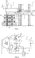
- Figs. 1 and 2 show an example of an offshore platform in the form of a jack-up platform 1 with a cantilever structure 2 projecting substantially horizontally from a platform hull 6 of the jack-up platform 1.
- the jack-up platform 1 according to the present example has three legs 3, 4, 5 carrying the platform hull 6, which is displaceable in vertical direction along the legs 3, 4, 5.
- the number of legs may also be different, e.g. one, two, four, five, six or more legs.
- a cabin 7 accommodating control facilities, machinery and providing shelter or housing for a crew is arranged on the platform hull 6 at a forward side opposite of an aft side from which the cantilever structure 2 projects.
- the cantilever structure 2 projects aft from an aft side of the vessel.
- the cantilever structure may also project generally horizontally from another side of the vessel.
- the control facilities may also be positioned elsewhere, e.g. on the cantilever or on the deck of the platform, or portable remote control may be used.
- the cantilever structure 2 is composed of a cantilever guide 8 and a cantilever 12 guided thereby.
- the cantilever guide 8 is in the form of a skidding system having a fixed part in the form of transverse rails 9 fixedly mounted to the platform hull 6 of the jack-up platform 1 and a movable part 10, guided for guided movement relative to the fixed part 9.
- the movable part 10 of the cantilever guide 8 is formed by longitudinal rails 10 that are part of the elongated cantilever 12. In the present example two rails are provided, but other numbers of rails and/or other longitudinal guides and/or traction providing structures are also conceivable.
- Supports 11A-11D are guided by the rails 9 for guided displacement along the rails 9 so that the cantilever 12 is displaceable in substantially horizontal, transverse directions Y of the transverse rails 9, between extreme port and starboard positions.
- the cantilever 12 is guided to move over the supports 11A-11D by its longitudinal rails 10 guided by the supports 11A-11D, along a trajectory in substantially horizontal longitudinal X direction between a most proximal position and a most distal position while the supports 11A-11D are held stationary relative to the transverse rails 9.
- Displacement in other selected directions can be achieved by combination of movement of the supports 11A-11D along the transverse rails 9 and movement of the cantilever 12 with its longitudinal rails 10 over the supports 11A-11D.
- Each support 11A-11D has a skidding body guided by a longitudinal rail 10 and a skidding body guided by a transverse rail 9.
- During displacement in X-direction support loads determine wear of the skidding bodies guided by the longitudinal rails 10 and during displacement in Y-direction support loads determine wear of the skidding bodies guided by the transverse rails 9 occurs.
- For displacement in X-direction support loads are relevant for the skidding bodies guided by the longitudinal rails 10 and for displacement in Y-direction support loads are relevant for the skidding bodies guided by the transverse rails 9.
- the supports 11A-11D may also be mutually connected forming parts of a common intermediate member of the cantilever guide.
- a so-called X-Y cantilever skidding system is used that allows movement of the cantilever 12 in longitudinal (X) directions and transverse (Y) directions.
- Other cantilever guide arrangements can be provided for instance a guide arrangement allowing movement in X and Psi directions, i.e. allowing longitudinal and horizontal pivotal angular movement. Many variants are possible, such as a guide allowing movement in X and Y directions as well as pivotal Psi movement.
- the cantilever 12 projects from the fixed part 9 of the cantilever guide 8 and, in this example, has a drilling platform 13 carrying a drilling tower 14 at a distal end of the cantilever structure 2 for instance for performing drilling and other operations such as plugging wells 91-96 performed over a fixed platform 90.
- the cantilever structure may also carry a different well drilling or intervention facility, such as a crane or other equipment for performing operations such as well construction, maintenance, work over, plug and abandonment and/or installation of wind turbine or other natural energy converting installations.
- the cantilever structure 2 may also comprise a secondary cantilever carrying any of said facilities.
- Free space for the movement of the cantilever 12 can be limited due to the presence of boundary limiting elements, such as jack-up platform legs 3-5 including their related jacking houses and/or other items, such as accommodation housing 7, projecting upwardly from or arranged on top of the platform hull 6. Free space may also be limited by an adjacent fixed structure, such as fixed platform.
- boundary limiting elements such as jack-up platform legs 3-5 including their related jacking houses and/or other items, such as accommodation housing 7, projecting upwardly from or arranged on top of the platform hull 6.
- Free space may also be limited by an adjacent fixed structure, such as fixed platform.
- the cantilever structure 2 is preferably retracted further inboard than in the distal position and sea-fastened.
- the cantilever 12 and any facilities mounted thereto are preferably completely inboard of the platform, but a, preferably small, portion of the cantilever and/or of any facilities mounted thereto may still project outside of the platform 1.
- a theoretical maximum operational envelope 22 in top plan view of the area potentially occupied by the cantilever structure 2 is shown.
- the theoretical maximum operational envelope 22 is determined by maximum reach of the movement system, such as the X-Y skidding system of the embodiment of fig. 1 and fig. 2 .
- the boundary model contains only boundary limiting information about the maximum reach of the movement system, defining the boundaries of movement of the cantilever, resulting in the maximum theoretical operational envelope.
- the maximum reach is therefore substantially rectangular. It is to be understood that the maximum operational envelope determined by the maximum reach of the movement system can have different shapes depending on the movement system and the presence of boundary limiting elements.
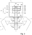
- FIG. 3 the platform 6 is more schematically represented and two of its legs 3, 4 are shown.
- a reference point 23 of the cantilever 12 is shown.
- the reference point 23 is constituted by a drilling axis of the drilling tower 14.
- the following drives are provided: movement of the cantilever 12 relative to the platform 6 in X-directions cantilever X-drives 32A-32D movement of the cantilever 12 relative to the platform 6 in Y-directions cantilever Y-drives 33A-33D
- the cantilever 12 As movement of the cantilever 12 is often intended to bring the drilling tower 14 in a desired position, e.g. above a well center of a jacket platform, it is for the operator convenient to have the drilling tower 14 as the reference point. This may also be visualized as such onto the interface accessible for the operator. In this example, the drilling axis 23 can be moved within the boundary envelope 24.
- movement may automatically be controlled to be restricted to movement within the boundary envelope 24 as is described in Dutch patent application 2 018 499 .
- a conventional approach would be, to control the drives 32A-32D and 33A-33D to first skid the cantilever 12 in X-direction along the guides 10 so that the drilling axis 23 moves along trajectory 36A and to subsequently skid the cantilever 12 transversely along the guides 9 in the Y-direction so that the drilling axis 23 moves along trajectory 36B to the target position 23B.
- the cantilever 12 would first be skidded in Y-direction along the guides 9 so that the drilling axis 23 moves along trajectory 36A' and subsequently be skidded longitudinally along the guides 10 in the X-direction so that the drilling axis 23 moves along trajectory 36B' to the target position 23B.
- a line 35 indicates positions of the drilling axis 23 that are associated to positions in which the cantilever 12 including items and other loads carried thereby, such as a drilling tower and a drilling floor is balanced relative to a line centrally between the guides 9, so that forces transferred via the supports 11A-11D are low and most evenly distributed.
- skidding of the cantilever 12 in Y-direction along the guides 9 entails a small and most evenly distributed amount of wear per unit of distance of displacement.
- the position in X-direction in which wear per unit of skidding displacement is most evenly distributed may be located further forward or aft.
- a trajectory is determined by applying a method represented by the flow chart shown in Fig. 4 .
- current position data representing a current position 23A of the drilling axis 23 of the cantilever structure 2 and target position data representing a target position of the drilling axis are read by the control system (steps 50 and 51).
- the current position may for instance be read from position sensors of the cantilever or be copied from target position data of a previous displacement.
- the new target position data may for instance be inputted by an operator or read from a system in which successive positions of the drilling axis have been stored previously.
- position dependent support load data associating support loads to a plurality of positions of the drilling axis 23 are read (step 52). These data may for instance be represented by a map associating co-ordinates of positions in that map to support loads.
- a standard or initial trajectory for displacement from the current, starting position 23A to the target position 23B is determined (step 53).
- the initially determined trajectory may for example be a trajectory formed by displacement 36A in X-direction followed by displacement 36B in Y-direction. This displacement involves skidding of the cantilever 12 in X-direction in which the guides 10 move along associated ones of the supports 11A-11D and, subsequently, skidding in Y-direction in which the supports 11A-11D skid along associated ones of the guides 9.
- a low wear trajectory 37 from the current position 23A to the target position 23B is determined from the current position data, the target position data and the position dependent support load data (step 54) and then movement of the cantilever structure 2 is controlled by controlling cantilever skidding drives 32A-32D-and 33A-33D to follow that trajectory (step 55).
- the low wear trajectory is composed of sections 37A-37C in which skidding along different guides 9, 10 is carried out sequentially.
- Movement along a first section 37A of the trajectory is achieved by skidding the cantilever in X-direction towards a position in which the drilling axis 23 is on line 35, where forces are distributed evenly between, on the one hand, aft supports 11A and 11B and, on the other hand, forward supports 11C and 11D. In that intermediate position, forces are also evenly distributed between the guide rails 9.
- movement along a third section 37C of the trajectory is achieved by skidding the guide rails 10 along the supports 11A-11D in X-direction until the cantilever 12 reaches the required position in X-direction corresponding to the X coordinate of the target position 23B as well, so the drilling axis 23 reaches the target position 23B.
- skidding movements that result in lowering support loads and/or an even distribution of support loads are carried out first, then skidding with reduced and/or evenly distributed support loads is carried out and then skidding for a final approach of the target position is carried out, wear of the skidding pads and/or skidding rollers is reduced and or more evenly distributed, so that maintenance intervals of the skidding pads and/or skidding rollers can be extended. Also, reduced support loads during skidding reduce the amount of power that is required for skidding and/or allow faster skidding.
- the support loads may be forces exerted via the supports, but may alternatively be loads expressed in terms of support wear, or more specifically wear of skidding bodies wear, such as skidding pads and/or skidding rollers. Such wear loads can be calculated from a wear function and support forces exerted via said supports. Thus, differences in resistance to wear of different guides and/or of different supports guided thereby may be taken into account when determining optimal intermediate skidding positions. Also wear loads can be expressed in relation to remaining wear capacity for shifting further wear from skidding bodies that are worn to a relatively large extent, to skidding bodies that are worn to a relatively small extent. The extent to which skidding bodies are worn can for instance be determined from historic wear load data and displacements, from measurements of the skidding bodies and/or from signals from (partial) wear sensors.
- Such a wear function may be a non linear function which is progressive, at least beyond a given support force level.
- the position dependent support load data may be calculated from a cantilever center of gravity position, cantilever weight, cantilever load weight, cantilever load center of gravity and support positions or be calculated by extrapolation or interpolation of measured support forces in at least two different positions.
- the mounting may be permanently fixed or removably or releasably fixed, the latter allowing dismounting or adjustment of the mounting position.
- the cantilever structure In the retracted position, the cantilever structure may be fully retracted within a top plan view contour of the jack-up platform or project horizontally outside of that contour, but less far than in the distal position.
- the secondary cantilever in the retracted position, may be fully retracted in the longitudinal direction relative to the primary cantilever or project horizontally in longitudinal direction beyond the primary cantilever, but less far than in the distal position.
Landscapes
- Engineering & Computer Science (AREA)
- Life Sciences & Earth Sciences (AREA)
- Geology (AREA)
- Mining & Mineral Resources (AREA)
- Physics & Mathematics (AREA)
- General Engineering & Computer Science (AREA)
- Mechanical Engineering (AREA)
- Geochemistry & Mineralogy (AREA)
- General Life Sciences & Earth Sciences (AREA)
- Fluid Mechanics (AREA)
- Environmental & Geological Engineering (AREA)
- Civil Engineering (AREA)
- Structural Engineering (AREA)
- General Physics & Mathematics (AREA)
- Automation & Control Theory (AREA)
- Earth Drilling (AREA)
Claims (12)
- Verfahren zum Steuern der Bewegung einer Auslegerstruktur (2) einer Offshore-Plattform (1), wie einer Hubplattform oder eines selbsthebenden Schiffs, wobei die Auslegerstruktur (2) in einer Längsrichtung (X) langgestreckt und mit einem Rumpf (6) der Plattform (1) über Stützen (11A-D) und Schlittenführungen (9, 10) gekoppelt ist, wobei die Stützen (11A-D) und die Schlittenführungen (9, 10) für eine geführte Schlittenverschiebung der Stützen (11A-D) entlang zugeordneter Schlittenführungen (9, 10) angeordnet sind, wobei das Verfahren umfasst:- Lesen von aktuellen Positionsdaten, die eine aktuelle Position (23A) eines Elements auf oder an der Auslegerstruktur (2) darstellen;- Lesen von Zielpositionsdaten, die eine Zielposition (23B) des Elements darstellen;- Lesen von positionsabhängigen Stützlastdaten, die Stützlasten wenigstens mehreren Positionen des Elements zuordnen;- Bestimmen, aus den aktuellen Positionsdaten und den Zielpositionsdaten, von Verschiebungen, die zum Verschieben des Elements zu der Zielposition (23B) erforderlich sind, einschließlich einer Längsschlittenverschiebung (36A) von ersten der Stützen (11A-D) des Auslegers (12) in der Längsrichtung (X) und einer Querschlittenverschiebung (36B) von zweiten der Stützen (11A-D) des Auslegers in einer horizontalen Richtung quer zu der Längsrichtung;- Bestimmen von Stützlasten aus den positionsabhängigen Stützlastdaten während der bestimmten Längsschlittenverschiebung (36A);- Bestimmen einer verschleißarmen Bahn (37) des Elements von der aktuellen Position (23A) zu der Zielposition (23B), in der, wenn und solange eine Summe von Stützlasten oder eine höchste Stützlast während der Längsschlittenverschiebung (36A) in Richtung der Zielposition (23B) abnimmt, die Längsschlittenverschiebung (36A) in Richtung der Zielposition (23B) der Querschlittenverschiebung (36B) vorausgeht, und, wenn eine Summe von Stützlasten oder eine höchste Stützlast während der Längsschlittenverschiebung (36A) in Richtung der Zielposition (23B) zunimmt, die Querschlittenverschiebung (36B) in Richtung der Zielposition (23B) der Längsschlittenverschiebung (36A) vorausgeht; und- Steuern der Bewegung der Auslegerstruktur (2) entsprechend der verschleiß armen Bahn (37).
- Verfahren nach Anspruch 1, das ferner eine
Längsschlittenverschiebung von der Zielposition (23B) weg umfasst, die der Querschlittenverschiebung (36B) vorausgeht, wenn die Stützlasten während der Längsschlittenverschiebung von der Zielposition (23B) weg geringer sind als die Stützlasten während der Längsschlittenverschiebung (36A) in Richtung der Zielposition (23B). - Verfahren nach Anspruch 2, ferner umfassend eine Längsschlittenverschiebung weg von der Zielposition, die der Querschlittenverschiebung (36B) vorausgeht, wenn ein Integral aus Stützverschleiß über die Längs- und Querverschiebungen geringer ist als ein Integral aus Stützverschleiß über die Längs- und Querverschiebungen ohne die Längsschlittenverschiebung weg von der Zielposition, wobei der Stützverschleiß aus einer Funktion des Verschleißes und der Stützkraft und aus bestimmten Stützlastkräften, die über die Stützen (11A-D) ausgeübt werden, berechnet wird.
- Verfahren nach Anspruch 3, wobei die Verschleißfunktion eine nicht lineare Funktion ist, die wenigstens über einem bestimmten Stützkraftniveau progressiv ist.
- Verfahren nach Anspruch 3 oder 4, ferner umfassend das Anpassen der Verschleißfunktion für jede Stütze (11A-D) oder jeden Schlittenkörper (9, 10) als Reaktion auf einen berechneten oder gemessenen Verschleiß dieser Stütze (11A-D) oder dieses Schlittenkörpers (9, 10), so dass der angepasste Stützenverschleiß als Reaktion auf eine verbleibende operative Verschleißkapazität dieser Stütze (11A-D) oder dieses Schlittenkörpers (9, 10), die verringert wird, erhöht wird.
- Verfahren nach Anspruch 5, wobei der angepasste Stützen- oder Schlittenkörperverschleiß als Bruchteil der verbleibenden operativen Verschleißkapazität ausgedrückt wird.
- Verfahren nach einem der vorhergehenden Ansprüche, wobei die positionsabhängigen Stützlastdaten eine Karte der Positionen des Elements und der zugeordneten Stützlasten darstellen.
- Verfahren nach einem der vorhergehenden Ansprüche, wobei die positionsabhängigen Stützlastdaten aus einer Ausleger-Schwerpunktposition, einem Auslegergewicht, einem Auslegerlastgewicht, einem Auslegerlastschwerpunkt und Stützpositionen berechnet werden.
- Verfahren nach einem der Ansprüche 1 bis 4, wobei die positionsabhängigen Stützlastdaten durch Extrapolation oder Interpolation von gemessenen Stützkräften berechnet werden.
- System zum Steuern der Bewegung einer Auslegerstruktur (2) einer Offshore-Plattform (1), wie einer Hubplattform oder eines selbsthebenden Schiffes, wobei die Auslegerstruktur (2) in einer Längsrichtung (X) langgestreckt und mit einem Rumpf (6) der Plattform (1) über Stützen (11A-D) und Schlittenführungen (9,10) gekoppelt ist, wobei die Stützen (11A-D) und die Schlittenführungen (9,10) für eine geführte Schlittenverschiebung der Stützen (11A-D) entlang zugeordneter Schlittenführungen (9, 10) angeordnet sind, wobei das System angeordnet ist zum:- Lesen von aktuellen Positionsdaten, die eine aktuelle Position (23A) eines Elements auf oder an der Auslegerstruktur (2) darstellen;- Lesen von Zielpositionsdaten, die eine Zielposition (23B) des Elements darstellen;- Lesen von positionsabhängigen Stützlastdaten, die Stützlasten wenigstens mehreren Positionen des Elements zuordnen;- Bestimmen, aus den aktuellen Positionsdaten und den Zielpositionsdaten, von Verschiebungen, die zum Verschieben des Elements zu der Zielposition (23B) erforderlich sind, einschließlich einer Längsschlittenverschiebung (36A) von ersten der Stützen (11A-D) des Auslegers (12) in der Längsrichtung (X) und einer Querschlittenverschiebung (36B) von zweiten der Stützen (11A-D) des Auslegers (12) in einer horizontalen Richtung quer zu der Längsrichtung;- Bestimmen von Stützlasten aus den positionsabhängigen Stützlastdaten während der bestimmten Längsschlittenverschiebung (36A);- Bestimmen einer verschleißarmen Bahn (37) des Elements von der aktuellen Position (23A) zu der Zielposition (23B), in der, wenn und solange eine Summe von Stützlasten oder eine höchste Stützlast während der Längsschlittenverschiebung (36A) in Richtung der Zielposition (23B) abnimmt, die Längsschlittenverschiebung (36A) in Richtung der Zielposition (23B) der Querschlittenverschiebung (36B) vorausgeht, und, wenn eine Summe von Stützlasten oder eine höchste Stützlast während der Längsschlittenverschiebung (36A) in Richtung der Zielposition (23B) zunimmt, die Querschlittenverschiebung (36B) in Richtung der Zielposition (23B) der Längsschlittenverschiebung (36A) vorausgeht; und- Steuern der Bewegung der Auslegerstruktur (2) entsprechend der verschleiß armen Bahn (37).
- Offshore-Plattform (1) umfassend ein System nach Anspruch 10.
- Computerprogrammprodukt in computerausführbarer Form, das, wenn es von einem Computer ausgeführt wird, angeordnet ist zum:Steuern der Bewegung einer Auslegerstruktur (2) einer Offshore-Plattform (1), wie einer Hubplattform oder eines selbsthebenden Schiffes, wobei die Auslegerstruktur (2) in einer Längsrichtung (X) langgestreckt und mit einem Rumpf (6) der Plattform (1) über Stützen (11A-D) und Schlittenführungen (9, 10) gekoppelt ist, wobei die Stützen (11A-D) und die Schlittenführungen (9, 10) für eine geführte Schlittenverschiebung der Stützen (11A-D) entlang zugeordneter Schlittenführungen (9, 10) angeordnet sind, wobei das Verfahren umfasst:- Lesen von aktuellen Positionsdaten, die eine aktuelle Position (23A) eines Elements auf oder an der Auslegerstruktur darstellen;- Lesen von Zielpositionsdaten, die eine Zielposition (23B) des Elements darstellen;- Lesen von positionsabhängigen Stützlastdaten, die Stützlasten wenigstens mehreren Positionen des Elements zuordnen;- Bestimmen, aus den aktuellen Positionsdaten und den Zielpositionsdaten, von Verschiebungen, die zum Verschieben des Elements zu der Zielposition (23B) erforderlich sind, einschließlich einer Längsschlittenverschiebung (36A) von ersten der Stützen (11A-D) des Auslegers (2) in der Längsrichtung (X) und einer Querschlittenverschiebung (36B) von zweiten der Stützen (11A-D) des Auslegers (2) in einer horizontalen Richtung quer zu der Längsrichtung;- Bestimmen von Stützlasten aus den positionsabhängigen Stützlastdaten während der bestimmten Längsschlittenverschiebung (36A);- Bestimmen einer verschleißarmen Bahn (37) des Elements von der aktuellen Position (23A) zu der Zielposition (23B), in der, wenn und solange eine Summe von Stützlasten oder eine höchste Stützlast während der Längsschlittenverschiebung (36A) in Richtung der Zielposition (23B) abnimmt, die Längsschlittenverschiebung (36A) in Richtung der Zielposition (23B) der Querschlittenverschiebung (36B) vorausgeht, und, wenn eine Summe von Stützlasten oder eine höchste Stützlast während der Längsschlittenverschiebung (36A) in Richtung der Zielposition (23B) zunimmt, die Querschlittenverschiebung (36B) in Richtung der Zielposition (23B) der Längsschlittenverschiebung (36A) vorausgeht; und- Steuern der Bewegung der Auslegerstruktur (2) entsprechend der verschleiß armen Bahn (37).
Applications Claiming Priority (2)
| Application Number | Priority Date | Filing Date | Title |
|---|---|---|---|
| NL2021625A NL2021625B1 (en) | 2018-09-13 | 2018-09-13 | Controlling movement of a cantilever structure of an offshore platform |
| PCT/NL2019/050592 WO2020055250A1 (en) | 2018-09-13 | 2019-09-12 | Controlling movement of a cantilever structure of an offshore platform |
Publications (2)
| Publication Number | Publication Date |
|---|---|
| EP3850159A1 EP3850159A1 (de) | 2021-07-21 |
| EP3850159B1 true EP3850159B1 (de) | 2022-12-28 |
Family
ID=64316939
Family Applications (1)
| Application Number | Title | Priority Date | Filing Date |
|---|---|---|---|
| EP19783159.7A Active EP3850159B1 (de) | 2018-09-13 | 2019-09-12 | Steuerung der bewegung einer freitragenden struktur einer offshore-plattform |
Country Status (5)
| Country | Link |
|---|---|
| US (1) | US11702812B2 (de) |
| EP (1) | EP3850159B1 (de) |
| DK (1) | DK3850159T3 (de) |
| NL (1) | NL2021625B1 (de) |
| WO (1) | WO2020055250A1 (de) |
Families Citing this family (1)
| Publication number | Priority date | Publication date | Assignee | Title |
|---|---|---|---|---|
| WO2016178576A2 (en) * | 2015-05-04 | 2016-11-10 | Gustomsc Resources B.V. | Drilling installation; handling system, method for independent operations |
Family Cites Families (19)
| Publication number | Priority date | Publication date | Assignee | Title |
|---|---|---|---|---|
| US3753552A (en) * | 1971-03-25 | 1973-08-21 | Fyron Jackson Inc | Displacement control system for hoist apparatus |
| US4516882A (en) * | 1982-06-11 | 1985-05-14 | Fluor Subsea Services, Inc. | Method and apparatus for conversion of semi-submersible platform to tension leg platform for conducting offshore well operations |
| NL1006889C2 (nl) | 1997-08-29 | 1999-03-02 | Marine Structure Consul | Boorinstallatie. |
| US6745852B2 (en) * | 2002-05-08 | 2004-06-08 | Anadarko Petroleum Corporation | Platform for drilling oil and gas wells in arctic, inaccessible, or environmentally sensitive locations |
| FR2865484B1 (fr) * | 2004-01-28 | 2006-05-19 | Technip France | Structure de transport, d'installation et de demantelement des elements d'une plate-forme petroliere fixe et procedes de mise en oeuvre d'une telle structure. |
| MY148240A (en) * | 2005-12-14 | 2013-03-29 | Gustomsc Resources Bv | Dual draft vessel |
| US20120027523A1 (en) * | 2010-07-29 | 2012-02-02 | GeoSea N.V. | Device and method for assembling a structure at sea |
| EP2823105B1 (de) * | 2012-03-06 | 2016-09-07 | Itrec B.V. | Offshore-system mit einem bohrgestell und einem ausleger |
| CA2890121A1 (en) * | 2012-11-06 | 2014-05-15 | DOGRA, Erik | Ship breaking down arrangement and method therefore |
| US9695565B2 (en) * | 2013-11-07 | 2017-07-04 | Zentech, Inc. | Jackup pedestal crane installation and operation, movable along a guide |
| NL2013409B1 (en) | 2014-09-03 | 2016-09-27 | Fugro N V | Spatial positioning of offshore structures. |
| NL2014407B1 (en) * | 2015-03-06 | 2016-10-13 | Gustomsc Resources Bv | Monohull drillship. |
| US20180044872A1 (en) * | 2015-03-09 | 2018-02-15 | Noble Drilling Services Inc. | Jackup drilling unit having material storage in jacking legs |
| WO2016178576A2 (en) * | 2015-05-04 | 2016-11-10 | Gustomsc Resources B.V. | Drilling installation; handling system, method for independent operations |
| EP3307955B1 (de) * | 2015-06-12 | 2022-11-30 | GustoMSC B.V. | Offshore-struktur, tragelement, gleitkufe, verfahren zum bewegen eines auslegers |
| WO2017095676A1 (en) * | 2015-12-01 | 2017-06-08 | Rowan Companies, Inc. | Dual operational rig |
| WO2018052283A1 (en) * | 2016-09-19 | 2018-03-22 | Gustomsc Resources B.V. | Extendable boom with a locking system and method for operating an extendable boom of a crane |
| NL2018499B1 (en) | 2017-03-10 | 2018-09-21 | Gustomsc Resources Bv | Method for monitoring movement of a cantilever structure of an offshore platform, monitoring system, offshore platform |
| NL2021708B1 (en) * | 2018-09-25 | 2020-05-07 | Gustomsc Resources Bv | Method for stabilizing a jack-up platform unit |
-
2018
- 2018-09-13 NL NL2021625A patent/NL2021625B1/en active
-
2019
- 2019-09-12 US US17/198,966 patent/US11702812B2/en active Active
- 2019-09-12 EP EP19783159.7A patent/EP3850159B1/de active Active
- 2019-09-12 DK DK19783159.7T patent/DK3850159T3/da active
- 2019-09-12 WO PCT/NL2019/050592 patent/WO2020055250A1/en not_active Ceased
Also Published As
| Publication number | Publication date |
|---|---|
| WO2020055250A1 (en) | 2020-03-19 |
| NL2021625B1 (en) | 2020-05-06 |
| EP3850159A1 (de) | 2021-07-21 |
| US11702812B2 (en) | 2023-07-18 |
| US20210388568A1 (en) | 2021-12-16 |
| DK3850159T3 (da) | 2023-02-20 |
Similar Documents
| Publication | Publication Date | Title |
|---|---|---|
| US11142287B2 (en) | System and method for compensation of motions of a floating vessel | |
| US6491477B2 (en) | Self-elevating drilling unit | |
| US7886845B2 (en) | Method and system for monitoring auxiliary operations on mobile drilling units and their application to improving drilling unit efficiency | |
| CA2828749C (en) | A cantilever system and method of use | |
| KR101691968B1 (ko) | 해양구조물의 스퍼드캔 안착위치 결정 장치 및 방법 | |
| KR20100087094A (ko) | 드릴링 장치를 리그에 설치하여 드릴링 작업을 준비하는 방법 | |
| de Araújo Neto et al. | Numerical evaluation of a subsea equipment installation method designed to avoid resonant responses | |
| US11702812B2 (en) | Controlling movement of a cantilever structure of an offshore platform | |
| CN101806053A (zh) | 自升式钻井平台悬臂梁的整体安装方法 | |
| NL2014726B1 (en) | Cantilever system for an offshore platform. | |
| CN201183947Y (zh) | 水上静力触探机 | |
| KR101665329B1 (ko) | 해양 작업 설치선의 레그 시스템 | |
| GB2150516A (en) | Marine vessels and moonpool structures therein | |
| KR20160022533A (ko) | 데릭 구조물의 승강 장치 및 이를 포함하는 시추선 | |
| KR20140122794A (ko) | 상하동요 보상장치 및 이를 구비한 시추선 | |
| US20180044872A1 (en) | Jackup drilling unit having material storage in jacking legs | |
| KR20190000193A (ko) | 도크를 이용한 데릭 로드 테스트 방법 | |
| KR20110094895A (ko) | 데릭 승강 구조 및 이를 포함하는 시추선 | |
| KR20120018892A (ko) | 유압식 선체 고정장치를 갖춘 해상 플랫폼 | |
| CN107991012B (zh) | 半潜式坐底平台底部冲刷淘空监测方法 | |
| KR101864748B1 (ko) | 해양구조물 | |
| WO2011059918A1 (en) | Tender assisted drilling spar | |
| KR20160062492A (ko) | 해양구조물의 히브모션 보상 제어시스템, 제어방법, 및 그 제어시스템을 갖는 해양구조물 | |
| KR20180113304A (ko) | 해양구조물 | |
| KR20170048837A (ko) | 캔틸레버 데릭 시스템 및 이를 가지는 해양 플랜트 |
Legal Events
| Date | Code | Title | Description |
|---|---|---|---|
| STAA | Information on the status of an ep patent application or granted ep patent |
Free format text: STATUS: UNKNOWN |
|
| STAA | Information on the status of an ep patent application or granted ep patent |
Free format text: STATUS: THE INTERNATIONAL PUBLICATION HAS BEEN MADE |
|
| PUAI | Public reference made under article 153(3) epc to a published international application that has entered the european phase |
Free format text: ORIGINAL CODE: 0009012 |
|
| STAA | Information on the status of an ep patent application or granted ep patent |
Free format text: STATUS: REQUEST FOR EXAMINATION WAS MADE |
|
| 17P | Request for examination filed |
Effective date: 20210413 |
|
| AK | Designated contracting states |
Kind code of ref document: A1 Designated state(s): AL AT BE BG CH CY CZ DE DK EE ES FI FR GB GR HR HU IE IS IT LI LT LU LV MC MK MT NL NO PL PT RO RS SE SI SK SM TR |
|
| DAV | Request for validation of the european patent (deleted) | ||
| DAX | Request for extension of the european patent (deleted) | ||
| GRAP | Despatch of communication of intention to grant a patent |
Free format text: ORIGINAL CODE: EPIDOSNIGR1 |
|
| STAA | Information on the status of an ep patent application or granted ep patent |
Free format text: STATUS: GRANT OF PATENT IS INTENDED |
|
| INTG | Intention to grant announced |
Effective date: 20220223 |
|
| GRAJ | Information related to disapproval of communication of intention to grant by the applicant or resumption of examination proceedings by the epo deleted |
Free format text: ORIGINAL CODE: EPIDOSDIGR1 |
|
| STAA | Information on the status of an ep patent application or granted ep patent |
Free format text: STATUS: REQUEST FOR EXAMINATION WAS MADE |
|
| GRAP | Despatch of communication of intention to grant a patent |
Free format text: ORIGINAL CODE: EPIDOSNIGR1 |
|
| STAA | Information on the status of an ep patent application or granted ep patent |
Free format text: STATUS: GRANT OF PATENT IS INTENDED |
|
| INTC | Intention to grant announced (deleted) | ||
| INTG | Intention to grant announced |
Effective date: 20220719 |
|
| GRAS | Grant fee paid |
Free format text: ORIGINAL CODE: EPIDOSNIGR3 |
|
| GRAA | (expected) grant |
Free format text: ORIGINAL CODE: 0009210 |
|
| STAA | Information on the status of an ep patent application or granted ep patent |
Free format text: STATUS: THE PATENT HAS BEEN GRANTED |
|
| AK | Designated contracting states |
Kind code of ref document: B1 Designated state(s): AL AT BE BG CH CY CZ DE DK EE ES FI FR GB GR HR HU IE IS IT LI LT LU LV MC MK MT NL NO PL PT RO RS SE SI SK SM TR |
|
| REG | Reference to a national code |
Ref country code: GB Ref legal event code: FG4D |
|
| REG | Reference to a national code |
Ref country code: CH Ref legal event code: EP |
|
| REG | Reference to a national code |
Ref country code: AT Ref legal event code: REF Ref document number: 1540545 Country of ref document: AT Kind code of ref document: T Effective date: 20230115 |
|
| REG | Reference to a national code |
Ref country code: IE Ref legal event code: FG4D |
|
| REG | Reference to a national code |
Ref country code: DE Ref legal event code: R096 Ref document number: 602019023733 Country of ref document: DE |
|
| REG | Reference to a national code |
Ref country code: NL Ref legal event code: FP |
|
| REG | Reference to a national code |
Ref country code: DK Ref legal event code: T3 Effective date: 20230213 |
|
| REG | Reference to a national code |
Ref country code: NO Ref legal event code: T2 Effective date: 20221228 |
|
| REG | Reference to a national code |
Ref country code: LT Ref legal event code: MG9D |
|
| PG25 | Lapsed in a contracting state [announced via postgrant information from national office to epo] |
Ref country code: SE Free format text: LAPSE BECAUSE OF FAILURE TO SUBMIT A TRANSLATION OF THE DESCRIPTION OR TO PAY THE FEE WITHIN THE PRESCRIBED TIME-LIMIT Effective date: 20221228 Ref country code: LT Free format text: LAPSE BECAUSE OF FAILURE TO SUBMIT A TRANSLATION OF THE DESCRIPTION OR TO PAY THE FEE WITHIN THE PRESCRIBED TIME-LIMIT Effective date: 20221228 Ref country code: FI Free format text: LAPSE BECAUSE OF FAILURE TO SUBMIT A TRANSLATION OF THE DESCRIPTION OR TO PAY THE FEE WITHIN THE PRESCRIBED TIME-LIMIT Effective date: 20221228 |
|
| REG | Reference to a national code |
Ref country code: AT Ref legal event code: MK05 Ref document number: 1540545 Country of ref document: AT Kind code of ref document: T Effective date: 20221228 |
|
| PG25 | Lapsed in a contracting state [announced via postgrant information from national office to epo] |
Ref country code: RS Free format text: LAPSE BECAUSE OF FAILURE TO SUBMIT A TRANSLATION OF THE DESCRIPTION OR TO PAY THE FEE WITHIN THE PRESCRIBED TIME-LIMIT Effective date: 20221228 Ref country code: LV Free format text: LAPSE BECAUSE OF FAILURE TO SUBMIT A TRANSLATION OF THE DESCRIPTION OR TO PAY THE FEE WITHIN THE PRESCRIBED TIME-LIMIT Effective date: 20221228 Ref country code: HR Free format text: LAPSE BECAUSE OF FAILURE TO SUBMIT A TRANSLATION OF THE DESCRIPTION OR TO PAY THE FEE WITHIN THE PRESCRIBED TIME-LIMIT Effective date: 20221228 Ref country code: GR Free format text: LAPSE BECAUSE OF FAILURE TO SUBMIT A TRANSLATION OF THE DESCRIPTION OR TO PAY THE FEE WITHIN THE PRESCRIBED TIME-LIMIT Effective date: 20230329 |
|
| P01 | Opt-out of the competence of the unified patent court (upc) registered |
Effective date: 20230516 |
|
| PG25 | Lapsed in a contracting state [announced via postgrant information from national office to epo] |
Ref country code: SM Free format text: LAPSE BECAUSE OF FAILURE TO SUBMIT A TRANSLATION OF THE DESCRIPTION OR TO PAY THE FEE WITHIN THE PRESCRIBED TIME-LIMIT Effective date: 20221228 Ref country code: RO Free format text: LAPSE BECAUSE OF FAILURE TO SUBMIT A TRANSLATION OF THE DESCRIPTION OR TO PAY THE FEE WITHIN THE PRESCRIBED TIME-LIMIT Effective date: 20221228 Ref country code: PT Free format text: LAPSE BECAUSE OF FAILURE TO SUBMIT A TRANSLATION OF THE DESCRIPTION OR TO PAY THE FEE WITHIN THE PRESCRIBED TIME-LIMIT Effective date: 20230428 Ref country code: ES Free format text: LAPSE BECAUSE OF FAILURE TO SUBMIT A TRANSLATION OF THE DESCRIPTION OR TO PAY THE FEE WITHIN THE PRESCRIBED TIME-LIMIT Effective date: 20221228 Ref country code: EE Free format text: LAPSE BECAUSE OF FAILURE TO SUBMIT A TRANSLATION OF THE DESCRIPTION OR TO PAY THE FEE WITHIN THE PRESCRIBED TIME-LIMIT Effective date: 20221228 Ref country code: CZ Free format text: LAPSE BECAUSE OF FAILURE TO SUBMIT A TRANSLATION OF THE DESCRIPTION OR TO PAY THE FEE WITHIN THE PRESCRIBED TIME-LIMIT Effective date: 20221228 Ref country code: AT Free format text: LAPSE BECAUSE OF FAILURE TO SUBMIT A TRANSLATION OF THE DESCRIPTION OR TO PAY THE FEE WITHIN THE PRESCRIBED TIME-LIMIT Effective date: 20221228 |
|
| PG25 | Lapsed in a contracting state [announced via postgrant information from national office to epo] |
Ref country code: SK Free format text: LAPSE BECAUSE OF FAILURE TO SUBMIT A TRANSLATION OF THE DESCRIPTION OR TO PAY THE FEE WITHIN THE PRESCRIBED TIME-LIMIT Effective date: 20221228 Ref country code: PL Free format text: LAPSE BECAUSE OF FAILURE TO SUBMIT A TRANSLATION OF THE DESCRIPTION OR TO PAY THE FEE WITHIN THE PRESCRIBED TIME-LIMIT Effective date: 20221228 Ref country code: IS Free format text: LAPSE BECAUSE OF FAILURE TO SUBMIT A TRANSLATION OF THE DESCRIPTION OR TO PAY THE FEE WITHIN THE PRESCRIBED TIME-LIMIT Effective date: 20230428 Ref country code: AL Free format text: LAPSE BECAUSE OF FAILURE TO SUBMIT A TRANSLATION OF THE DESCRIPTION OR TO PAY THE FEE WITHIN THE PRESCRIBED TIME-LIMIT Effective date: 20221228 |
|
| REG | Reference to a national code |
Ref country code: DE Ref legal event code: R097 Ref document number: 602019023733 Country of ref document: DE |
|
| PLBE | No opposition filed within time limit |
Free format text: ORIGINAL CODE: 0009261 |
|
| STAA | Information on the status of an ep patent application or granted ep patent |
Free format text: STATUS: NO OPPOSITION FILED WITHIN TIME LIMIT |
|
| 26N | No opposition filed |
Effective date: 20230929 |
|
| PG25 | Lapsed in a contracting state [announced via postgrant information from national office to epo] |
Ref country code: SI Free format text: LAPSE BECAUSE OF FAILURE TO SUBMIT A TRANSLATION OF THE DESCRIPTION OR TO PAY THE FEE WITHIN THE PRESCRIBED TIME-LIMIT Effective date: 20221228 |
|
| REG | Reference to a national code |
Ref country code: DE Ref legal event code: R119 Ref document number: 602019023733 Country of ref document: DE |
|
| REG | Reference to a national code |
Ref country code: CH Ref legal event code: PL |
|
| PG25 | Lapsed in a contracting state [announced via postgrant information from national office to epo] |
Ref country code: LU Free format text: LAPSE BECAUSE OF NON-PAYMENT OF DUE FEES Effective date: 20230912 |
|
| REG | Reference to a national code |
Ref country code: BE Ref legal event code: MM Effective date: 20230930 |
|
| PG25 | Lapsed in a contracting state [announced via postgrant information from national office to epo] |
Ref country code: LU Free format text: LAPSE BECAUSE OF NON-PAYMENT OF DUE FEES Effective date: 20230912 Ref country code: IT Free format text: LAPSE BECAUSE OF FAILURE TO SUBMIT A TRANSLATION OF THE DESCRIPTION OR TO PAY THE FEE WITHIN THE PRESCRIBED TIME-LIMIT Effective date: 20221228 Ref country code: MC Free format text: LAPSE BECAUSE OF FAILURE TO SUBMIT A TRANSLATION OF THE DESCRIPTION OR TO PAY THE FEE WITHIN THE PRESCRIBED TIME-LIMIT Effective date: 20221228 |
|
| REG | Reference to a national code |
Ref country code: IE Ref legal event code: MM4A |
|
| PG25 | Lapsed in a contracting state [announced via postgrant information from national office to epo] |
Ref country code: IE Free format text: LAPSE BECAUSE OF NON-PAYMENT OF DUE FEES Effective date: 20230912 |
|
| PG25 | Lapsed in a contracting state [announced via postgrant information from national office to epo] |
Ref country code: CH Free format text: LAPSE BECAUSE OF NON-PAYMENT OF DUE FEES Effective date: 20230930 |
|
| PG25 | Lapsed in a contracting state [announced via postgrant information from national office to epo] |
Ref country code: IE Free format text: LAPSE BECAUSE OF NON-PAYMENT OF DUE FEES Effective date: 20230912 Ref country code: FR Free format text: LAPSE BECAUSE OF NON-PAYMENT OF DUE FEES Effective date: 20230930 Ref country code: DE Free format text: LAPSE BECAUSE OF NON-PAYMENT OF DUE FEES Effective date: 20240403 Ref country code: CH Free format text: LAPSE BECAUSE OF NON-PAYMENT OF DUE FEES Effective date: 20230930 |
|
| PG25 | Lapsed in a contracting state [announced via postgrant information from national office to epo] |
Ref country code: BE Free format text: LAPSE BECAUSE OF NON-PAYMENT OF DUE FEES Effective date: 20230930 |
|
| PG25 | Lapsed in a contracting state [announced via postgrant information from national office to epo] |
Ref country code: BG Free format text: LAPSE BECAUSE OF FAILURE TO SUBMIT A TRANSLATION OF THE DESCRIPTION OR TO PAY THE FEE WITHIN THE PRESCRIBED TIME-LIMIT Effective date: 20221228 |
|
| PG25 | Lapsed in a contracting state [announced via postgrant information from national office to epo] |
Ref country code: BG Free format text: LAPSE BECAUSE OF FAILURE TO SUBMIT A TRANSLATION OF THE DESCRIPTION OR TO PAY THE FEE WITHIN THE PRESCRIBED TIME-LIMIT Effective date: 20221228 |
|
| PG25 | Lapsed in a contracting state [announced via postgrant information from national office to epo] |
Ref country code: CY Free format text: LAPSE BECAUSE OF FAILURE TO SUBMIT A TRANSLATION OF THE DESCRIPTION OR TO PAY THE FEE WITHIN THE PRESCRIBED TIME-LIMIT; INVALID AB INITIO Effective date: 20190912 |
|
| PG25 | Lapsed in a contracting state [announced via postgrant information from national office to epo] |
Ref country code: HU Free format text: LAPSE BECAUSE OF FAILURE TO SUBMIT A TRANSLATION OF THE DESCRIPTION OR TO PAY THE FEE WITHIN THE PRESCRIBED TIME-LIMIT; INVALID AB INITIO Effective date: 20190912 |
|
| PGFP | Annual fee paid to national office [announced via postgrant information from national office to epo] |
Ref country code: NL Payment date: 20250704 Year of fee payment: 7 |
|
| PGFP | Annual fee paid to national office [announced via postgrant information from national office to epo] |
Ref country code: DK Payment date: 20250911 Year of fee payment: 7 |
|
| PGFP | Annual fee paid to national office [announced via postgrant information from national office to epo] |
Ref country code: NO Payment date: 20250909 Year of fee payment: 7 |
|
| PGFP | Annual fee paid to national office [announced via postgrant information from national office to epo] |
Ref country code: GB Payment date: 20250703 Year of fee payment: 7 |
|
| PG25 | Lapsed in a contracting state [announced via postgrant information from national office to epo] |
Ref country code: TR Free format text: LAPSE BECAUSE OF FAILURE TO SUBMIT A TRANSLATION OF THE DESCRIPTION OR TO PAY THE FEE WITHIN THE PRESCRIBED TIME-LIMIT Effective date: 20221228 |