EP3849920B1 - Plastic aerosol bottle - Google Patents
Plastic aerosol bottle Download PDFInfo
- Publication number
- EP3849920B1 EP3849920B1 EP19765729.9A EP19765729A EP3849920B1 EP 3849920 B1 EP3849920 B1 EP 3849920B1 EP 19765729 A EP19765729 A EP 19765729A EP 3849920 B1 EP3849920 B1 EP 3849920B1
- Authority
- EP
- European Patent Office
- Prior art keywords
- container
- notably
- bottle
- thickness
- neck
- Prior art date
- Legal status (The legal status is an assumption and is not a legal conclusion. Google has not performed a legal analysis and makes no representation as to the accuracy of the status listed.)
- Active
Links
Images

Classifications
-
- B—PERFORMING OPERATIONS; TRANSPORTING
- B65—CONVEYING; PACKING; STORING; HANDLING THIN OR FILAMENTARY MATERIAL
- B65D—CONTAINERS FOR STORAGE OR TRANSPORT OF ARTICLES OR MATERIALS, e.g. BAGS, BARRELS, BOTTLES, BOXES, CANS, CARTONS, CRATES, DRUMS, JARS, TANKS, HOPPERS, FORWARDING CONTAINERS; ACCESSORIES, CLOSURES, OR FITTINGS THEREFOR; PACKAGING ELEMENTS; PACKAGES
- B65D83/00—Containers or packages with special means for dispensing contents
- B65D83/14—Containers for dispensing liquid or semi-liquid contents by internal gaseous pressure, i.e. aerosol containers comprising propellant
- B65D83/38—Details of the container body
-
- B—PERFORMING OPERATIONS; TRANSPORTING
- B65—CONVEYING; PACKING; STORING; HANDLING THIN OR FILAMENTARY MATERIAL
- B65D—CONTAINERS FOR STORAGE OR TRANSPORT OF ARTICLES OR MATERIALS, e.g. BAGS, BARRELS, BOTTLES, BOXES, CANS, CARTONS, CRATES, DRUMS, JARS, TANKS, HOPPERS, FORWARDING CONTAINERS; ACCESSORIES, CLOSURES, OR FITTINGS THEREFOR; PACKAGING ELEMENTS; PACKAGES
- B65D1/00—Rigid or semi-rigid containers having bodies formed in one piece, e.g. by casting metallic material, by moulding plastics, by blowing vitreous material, by throwing ceramic material, by moulding pulped fibrous material or by deep-drawing operations performed on sheet material
- B65D1/02—Bottles or similar containers with necks or like restricted apertures, designed for pouring contents
- B65D1/0223—Bottles or similar containers with necks or like restricted apertures, designed for pouring contents characterised by shape
- B65D1/0261—Bottom construction
- B65D1/0276—Bottom construction having a continuous contact surface, e.g. Champagne-type bottom
-
- B—PERFORMING OPERATIONS; TRANSPORTING
- B29—WORKING OF PLASTICS; WORKING OF SUBSTANCES IN A PLASTIC STATE IN GENERAL
- B29C—SHAPING OR JOINING OF PLASTICS; SHAPING OF MATERIAL IN A PLASTIC STATE, NOT OTHERWISE PROVIDED FOR; AFTER-TREATMENT OF THE SHAPED PRODUCTS, e.g. REPAIRING
- B29C2949/00—Indexing scheme relating to blow-moulding
- B29C2949/07—Preforms or parisons characterised by their configuration
- B29C2949/076—Preforms or parisons characterised by their configuration characterised by the shape
- B29C2949/0768—Preforms or parisons characterised by their configuration characterised by the shape characterised by the shape of specific parts of preform
- B29C2949/077—Preforms or parisons characterised by their configuration characterised by the shape characterised by the shape of specific parts of preform characterised by the neck
- B29C2949/0772—Closure retaining means
- B29C2949/0776—Closure retaining means not containing threads
-
- B—PERFORMING OPERATIONS; TRANSPORTING
- B29—WORKING OF PLASTICS; WORKING OF SUBSTANCES IN A PLASTIC STATE IN GENERAL
- B29C—SHAPING OR JOINING OF PLASTICS; SHAPING OF MATERIAL IN A PLASTIC STATE, NOT OTHERWISE PROVIDED FOR; AFTER-TREATMENT OF THE SHAPED PRODUCTS, e.g. REPAIRING
- B29C2949/00—Indexing scheme relating to blow-moulding
- B29C2949/07—Preforms or parisons characterised by their configuration
- B29C2949/081—Specified dimensions, e.g. values or ranges
- B29C2949/0811—Wall thickness
- B29C2949/0813—Wall thickness of the neck
-
- B—PERFORMING OPERATIONS; TRANSPORTING
- B29—WORKING OF PLASTICS; WORKING OF SUBSTANCES IN A PLASTIC STATE IN GENERAL
- B29C—SHAPING OR JOINING OF PLASTICS; SHAPING OF MATERIAL IN A PLASTIC STATE, NOT OTHERWISE PROVIDED FOR; AFTER-TREATMENT OF THE SHAPED PRODUCTS, e.g. REPAIRING
- B29C2949/00—Indexing scheme relating to blow-moulding
- B29C2949/07—Preforms or parisons characterised by their configuration
- B29C2949/081—Specified dimensions, e.g. values or ranges
- B29C2949/0811—Wall thickness
- B29C2949/0816—Wall thickness of the flange
-
- B—PERFORMING OPERATIONS; TRANSPORTING
- B29—WORKING OF PLASTICS; WORKING OF SUBSTANCES IN A PLASTIC STATE IN GENERAL
- B29L—INDEXING SCHEME ASSOCIATED WITH SUBCLASS B29C, RELATING TO PARTICULAR ARTICLES
- B29L2031/00—Other particular articles
- B29L2031/712—Containers; Packaging elements or accessories, Packages
- B29L2031/7158—Bottles
Definitions
- the present invention relates to pressurized bottles, also known as aerosol bottles, the container of which is made of plastics material.
- the patent application FR 3 047 234 discloses a pressurized bottle having a container made of plastics material comprising a body that extends along a longitudinal axis and a neck that is integral with the body, the body having a portion with a substantially frustoconical shape extending over more than a third of the total height of the container.
- EP 0 653 982 discloses a method of making a polyester container having an enhanced level of crystallinity in the sidewall while maintaining a low level of crystallinity in a thickened base portion.
- the container is used as a refillable container which can withstand higher caustic wash temperatures and exhibits reduced flavor carryover, or as a hot-fill container.
- a sidewall-forming section of a preform is initially expanded, heated to contract and crystallize the same, and then reexpanded; a base-forming portion of the preform is shielded from the heat treatment and is expanded either before or after the heat treatment step.
- US 5 083 685 discloses a vessel for aerosol made of a synthetic resin.
- a plastic aerosol bottle should comply with regulations. Tests on a plastic aerosol bottle containing a liquefied gas are generally more difficult to satisfy than those relating to plastic aerosol bottles containing a compressed gas.
- the tests make it possible to verify that the plastic pressurized bottle is able to resist an operating pressure of generally several bar on account of the presence of a pressurized gas, notably a pressurized liquefied gas, inside it.
- a pressurized gas notably a pressurized liquefied gas
- This resistance has to be verified at a relatively high temperature in order to ensure safety in use.
- the bottle can be filled under vacuum, this ensures squeeze resistance when the reduced pressure is at a maximum, before filling is started.
- the bottle also has to be resistant to impacts, notably to being dropped at different temperatures.
- the regulatory tests to be carried out are thus drop tests, after 6 h at 55°C, after 24 h at -18°C and after 3 months at 40°C, the hot air test of 5 h at 75°C, the water bath at 54°C, two-month compatibility tests at room temperature and at 45°C, and a test pressure test and a bursting pressure test.
- a six-month test at room temperature and a three-year test at room temperature for verifying predictivity may also be mentioned.
- the invention aims to provide a bottle made of plastics material that meets all of these constraints in a satisfactory manner.
- the invention meets this need by virtue of a pressurized bottle having a container made of plastics according to claim 1.
- the minimum quantity of material associated with the thickness of the container in the indicated areas nevertheless gives the bottle mechanical strength that allows it to successfully undergo the abovementioned tests, with or without compressed air and water.
- the aerosol bottle can notably resist the ejection of the aerosol valve during the critical hot air test at 75°C.
- the bottle can remain stable after passing through a water bath at 54°C.
- These minimum thicknesses also allow the bottle not to craze after various tests.
- the minimum quantity of material i.e. the minimum thickness
- the minimum thickness is preferred for the various portions of the bottle, this minimum thickness being chosen, as indicated, so as to allow the bottle to successfully undergo the various regulatory tests.
- the container preferably has a thickness of at least 0.4 mm, notably at least 0.5 mm or 0.55 mm, or at least 0.60 mm or at least 0.65 mm, preferably a thickness between 0.4 mm and 0.80 mm, better between 0.60 mm and 0.80 mm, in a second portion with a height of at least 8 mm, for example a height of at least 10 mm, that is situated, starting from the upper end of the neck, at a distance of between 40% and 64% of the total height of the container.
- a thickness value at this location on the container makes it possible to avoid the deformation of the body of the container during the water bath test at 54°C.
- the container advantageously has a thickness of at least 0.4 mm, notably at least 0.5 mm, notably at least 0.55 mm or at least 0.6 mm, preferably a thickness between 0.4 mm and 0.69 mm, better between 0.55 mm and 0.69 mm in a third portion with a height of at least 8 mm that is situated, starting from the upper end of the neck, at a distance of between 65% and 91% of the total height of the container.
- a thickness value at this location on the container makes it possible to avoid any breakage of the container during the drop test and also to avoid any deformation of the bottom of the container during the water bath test at 54°C.
- the container preferably has a thickness of at least 0.6 mm, notably at least 0.65 mm, notably at least 0.7 mm, preferably a thickness between 0.6 mm and 0.81 mm, better between 0.65 mm and 0.81 mm in a fourth portion that is situated, starting from the upper end of the neck, at a distance of between 92% and 98% of the total height of the container. This makes it possible to successfully undergo the hot air test and the drop test.
- Such a minimum thickness value at this location on the container makes it possible to avoid any breakage of the container during the drop test and also to avoid any deformation of the bottom of the container during the water bath test at 54°C.
- the body of the container may have a bottom that is designed to allow the container to stand vertically on a horizontal flat surface, the bottom comprising a downwardly concave indentation, the lower end of the body extending around this indentation, notably following a bottom line of circular contour that forms the lower end of the body.
- the concave indentation preferably has a crown at the center of which the thickness is at least 2.5 mm, notably at least 2.7 mm, for example a thickness equal to 2.5 mm, or a thickness comprised in the range between 2.5 mm and 3.13 mm.
- the thickness of the container halfway between the lower end of the body and the crown of the indentation may be equal to at least 1.8 mm, notably to at least 2 mm, preferably a thickness between 1.8 mm and 2.5 mm, for example a thickness equal to 1.8 mm. It is preferable for the thickness at this location to be uniform so as to avoid any asymmetric deformation of the container.
- the shape of the bottom and the minimum thickness of the bottom including the indentation make it possible to have resistance under pressure and to avoid asymmetric deformation of the bottle, and make it possible to successfully undergo the drop tests and the temperature tests, in particular the test in a water bath at 54°C.
- the height of the first portion or of each of the first, second and/or third portions, over which the thickness of the container is measured is preferably equal to 10 mm.
- said height is identical for each of the first, second and/or third portions.
- the body advantageously has a part with a substantially frustoconical, notably rectilinear, shape.
- This frustoconical shape is preferably flared downwardly for the stability of the container set down vertically on a horizontal flat surface.
- the first, second and third portions may be situated within said part with a substantially frustoconical shape.
- the neck has two rings that define an annular groove between one another, namely an upper ring and a supporting lower ring, the thickness of the neck in a portion substantially parallel to the longitudinal axis situated under the lower ring being at least 1.06 mm, for example at least 2.7 mm, notably at least 2.9 mm, preferably a thickness between 1.06 mm and 2.9 mm.
- the upper ring of the neck advantageously serves to crimp a dispensing valve cup and the lower ring, situated therebeneath, may serve to transport the container along production and/or filling lines.
- the neck may be joined to the body by a shoulder, the thickness of the container at the junction between the neck and the shoulder being at least 2 mm, notably at least 2.4 mm, preferably a thickness between 2 mm and 3 mm, preferably between 2 mm and 2.5 mm.
- the neck may be at least partially crystallized, notably above the shoulder and to a distance of around 2 mm below the supporting lower ring.
- the plastics material of the container advantageously includes at least one polymer chosen from the group consisting of PET or PETP (polyethylene terephthalate), PEN (polyethylene naphthalate), PCT (polycyclohexylenedimethylene terephthalate), recycled polymers, notably referred to as PCR (post-consumer recycled) polymers, in particular recycled PET, bioPET (biological polyethylene terephthalate), PP (polypropylene), PE (polyethylene), PEF (polyethylene furanoate), PET-G/PCT-G (glycolized polyethylene terephthalate/glycolized polycyclohexylenedimethylene terephthalate), PET with glass fibers, PC (polycarbonate), POM (polyoxymethylene), SMMA (styrene methyl methacrylate), PMMA (polymethyl methacrylate), SAN (styrene acrylonitrile), PBT (polybutadiene terephthalate),
- the container may contain a cosmetic product or the like.
- the container may contain a liquefied or compressed gas, with an overpressure of between 1 and 13 bar (10 5 and 13.10 5 Pa) at 20°C.
- the bottle may have a dispensing system for dispensing the cosmetic product contained in the container, being provided with an actuating member that the user can press in order to dispense the product through at least one outlet orifice, for example in the form of a spray, a foam, a gel or a cream.
- the dispensing system has for example a dispensing head bearing the actuating member and a cup, fastened to the container, bearing a valve with a hollow control stem to be controlled by being depressed or tilted.
- the bottle may also have a system of the Bag-on-Valve (BoV) type, forming an aerosol valve with a welded bag.
- BoV Bag-on-Valve
- the product is placed inside the bag while the propellant is filled into the space between the bag and the container.
- the product is dispensed by the propellant by simply pressing the bag.
- the actuating member is depressed, the product is extracted from the bag by the propellant, this creating the distribution notably in the form of a spray, cream or gel.
- the pressurized bottle 1 shown in the figures has a container 3 containing the product to be dispensed, for example a cosmetic product to be sprayed, and a dispensing system 2 mounted on the container 3.
- the dispensing system 2 can be realized in various ways, being provided with an actuating member 4 (visible notably in figures 2 and 3 ) that the user can press in order to dispense the product through at least one outlet orifice, for example in the form of a spray.
- an actuating member 4 visible notably in figures 2 and 3
- the user can press in order to dispense the product through at least one outlet orifice, for example in the form of a spray.
- the dispensing system 2 has a dispensing head bearing the actuating member 4 and a valve 7 with a hollow control stem 9 to be controlled by being depressed or tilted, having a cup 6 and shown schematically in figure 3 .
- the product contained in the container 3 leaves the valve stem 9 when the latter is actuated, and then reaches the outlet orifice of the dispensing head through one or more internal ducts thereof.
- the container 3 has a body 10 formed as a single piece that extends along a longitudinal axis X and is extended at its upper end by a neck 20, the entire container 3 made up of the body 10 and the neck 20 being made of thermoplastic material, for example PET.
- the formation of the container 3 may include the blow molding of a preform within a mold, in a manner known per se.
- the thermoplastic material of which the container 3 is made is for example transparent, at least in the region of the body 10.
- the neck 20 is at least partially concealed by a removable protective cap 8, which is fastened to the container for example by snap-fastening.
- the neck of the bottle may be concealed by a cup of the bottle, which is fastened to the cup of the valve.
- the body 10 has a frustoconical shape over a major part 11 of its height.
- the lower part 14 of the body 10 is rounded as far as a lower end 30 of the container that is formed at the bottom 15 of the container 3.
- the bottom 15 of the container 3 has an indentation 16, of outwardly concave shape, defined by a frustoconical wall 18 that converges towards the inside of the container.
- the frustoconical wall 18 is attached to a crown 19 of the indentation 16, forming in this example a substantially flat wall, which bears at its center 25 the trace of the injection point of the preform used to produce the container 3 by injection blow molding or compression blow molding.
- the container 3 has on its inside an annular groove 28 around the frustoconical wall 18, in which the end of a dip tube connected to the dispensing system 2 can extend if need be, this tube not being shown in figure 3 .
- This annular groove 28 forms the, substantially circular, bottom line 29, which is in contact with the horizontal surface on which the bottle 1 stands when it is positioned vertically.
- This bottom line 29, which forms the, closed, lower end 30 of the container 3, is referred to as the "standing line”.
- the neck 20 of the container 3 has an, open, upper end with an upper ring 21 that allows the dispensing system 2 to be attached and more particularly the cup 6 to be crimped.
- the neck 20 also has a lower ring 26, which can serve to transport the container along production and/or filling lines, and can be referred to as support ring or supporting lower ring.
- the neck 20 is crystallized over at least a part of its height, in the example illustrated as far as around 2 mm below the supporting lower ring 26. In a variant, the neck 20 is not crystallized.
- the upper ring 21 and lower ring 26 define a groove 70 between one another, the role of said groove being to allow the crimping pliers for the cup 6 to be fitted under the upper ring 21.
- the container 3 has a thickness e 1 of at least 1.06 mm in a first portion 40 with a height h 1 of 10 mm that is situated, starting from the upper end 22 of the neck, at a distance d 1 of between 10% and 40% of the total height H of the container 3.
- the height H measured between the upper end 22 and the lower end 30, is equal to 131 mm.
- the distance d 1 is equal to 20 mm, the first portion 40 therefore extending over a height ranging from 20 mm to 30 mm from the upper end 22.
- This minimum thickness e 1 makes it possible, during the hot air test at 75°C, to avoid ejection of the aerosol valve.
- the container 3 furthermore has, at the lower end 30 of the body 10, a minimum thickness e 5 of 2 mm, at the bottom line 29, as can be seen in figure 7 .
- the thickness e 5 is chosen so as to make it possible to have a container bottom which does not deform in an asymmetric manner and thus to maintain a bottle that is stable and not tilted with respect to the vertical.
- the volume of the container 3 in this example is 140 ml.
- the container 3 also has the following features.
- This minimum thickness e 2 makes it possible to have no problems during the vacuum test or during sleeve fitting, and possibly to avoid the deformation of the body of the container in the water bath test at 54°C.
- the container 3 has a thickness e 4 of at least 0.7 mm in a fourth portion 43 that is situated, starting from the upper end 22 of the neck 20, at a distance d 4 of between 92% and 98% of the total height H of the container 3.
- the fourth portion 43 does not have a significant height and is limited substantially to a line, as illustrated.
- the distance d 4 is equal to 126 mm in this example. This minimum thickness e 4 makes it possible to avoid any breakage of the container during the drop test or any deformation in the water bath at 54°C.
- the thickness ee is at least 2.7 mm.
- the thickness e 7 of the container 3 halfway between the lower end 30 of the body 10 and the crown 19 of the indentation 18 is equal to at least 2 mm. It is important for the thickness e 7 to be uniform around the circular perimeter of the indentation 18 in order to avoid asymmetric deformation of the container there.
- the height h 1 , h 2 and h 3 of the first, second and third portions, respectively, is identical for each of the portions and equal to 10 mm. It would not constitute a departure from the scope of the invention if this height were lower or higher, being at least 8 mm, or if the heights of the portions were different from one another.
- the variation in thickness of the container within the first, second and third portions is at most 20% in this example. This is a tolerance that makes it possible to ensure that there is not excessive variation in thickness within one and the same portion.
- first, second and third portions are situated mainly in the part 11 with a substantially frustoconical shape.
- the thickness e 8 thereof in a portion 44 parallel to the longitudinal axis X situated under the lower ring 26, as can be seen in figure 6 is at least 2.9 mm.
- the neck 20 is joined to the body 10 by a shoulder 45, the thickness e 9 of the container at the junction 46 between the neck 20 and the shoulder 45 being at least 2.4 mm.
- Container volume H d 1 d 2 d 3 d 4 110 ml 105.1 mm 20 mm 47 mm 77.6 mm 100.1 mm 210 ml 166.5 mm 20 mm 86.5 mm 139 mm 161.5 mm 110 ml 102.3 mm 20 mm 47 mm 74.8 mm 97.3 mm 210 ml 165.3 mm 20 mm 86.5 mm 137.8 mm 160.3 mm 210 ml 166.7 mm 20 mm 86.5 mm 139.2 mm 161.7 mm
- the thickness e 1 may be at least 0.9 mm
- the thickness e 2 may be at least 0.5 mm
- the thickness e 3 may be at least 0.5 mm
- the thickness e 4 may be at least 0.6 mm
- the thickness e 5 may be at least 1.4 mm
- the thickness e 6 may be at least 2.5 mm
- the thickness e 7 may be at least 1.8 mm
- the thickness e 8 may be at least 2.7 mm
- the thickness e 9 may be at least 2 mm, without departing from the scope of the invention.
- the height h 1 is equal to 6 mm and the heights h 2 and h 3 are equal to 10 mm.
Landscapes
- Engineering & Computer Science (AREA)
- Mechanical Engineering (AREA)
- Ceramic Engineering (AREA)
- Chemical & Material Sciences (AREA)
- Dispersion Chemistry (AREA)
- Containers Having Bodies Formed In One Piece (AREA)
- Containers And Packaging Bodies Having A Special Means To Remove Contents (AREA)
- Blow-Moulding Or Thermoforming Of Plastics Or The Like (AREA)
- Disintegrating Or Milling (AREA)
Description
- The present invention relates to pressurized bottles, also known as aerosol bottles, the container of which is made of plastics material.
- The
patent application FR 3 047 234 -
EP 0 653 982US 5 083 685 discloses a vessel for aerosol made of a synthetic resin. - A plastic aerosol bottle should comply with regulations. Tests on a plastic aerosol bottle containing a liquefied gas are generally more difficult to satisfy than those relating to plastic aerosol bottles containing a compressed gas.
- The tests make it possible to verify that the plastic pressurized bottle is able to resist an operating pressure of generally several bar on account of the presence of a pressurized gas, notably a pressurized liquefied gas, inside it. This resistance has to be verified at a relatively high temperature in order to ensure safety in use. Furthermore, since the bottle can be filled under vacuum, this ensures squeeze resistance when the reduced pressure is at a maximum, before filling is started. The bottle also has to be resistant to impacts, notably to being dropped at different temperatures.
- The regulatory tests to be carried out are thus drop tests, after 6 h at 55°C, after 24 h at -18°C and after 3 months at 40°C, the hot air test of 5 h at 75°C, the water bath at 54°C, two-month compatibility tests at room temperature and at 45°C, and a test pressure test and a bursting pressure test. A six-month test at room temperature and a three-year test at room temperature for verifying predictivity may also be mentioned.
- The invention aims to provide a bottle made of plastics material that meets all of these constraints in a satisfactory manner.
- The invention meets this need by virtue of a pressurized bottle having a container made of plastics according to
claim 1. - The minimum quantity of material associated with the thickness of the container in the indicated areas nevertheless gives the bottle mechanical strength that allows it to successfully undergo the abovementioned tests, with or without compressed air and water. The aerosol bottle can notably resist the ejection of the aerosol valve during the critical hot air test at 75°C. The bottle can remain stable after passing through a water bath at 54°C. These minimum thicknesses also allow the bottle not to craze after various tests. By virtue of these thicknesses, notably that of the lower end of the body, the bottom does not reverse, notably at a pressure of 8 bar, nor does it deform, for example by sagging of the bottom of the bottle, at the lower end of the body, in contact with a support. Advantageously, the minimum quantity of material, i.e. the minimum thickness, is preferred for the various portions of the bottle, this minimum thickness being chosen, as indicated, so as to allow the bottle to successfully undergo the various regulatory tests.
- The container preferably has a thickness of at least 0.4 mm, notably at least 0.5 mm or 0.55 mm, or at least 0.60 mm or at least 0.65 mm, preferably a thickness between 0.4 mm and 0.80 mm, better between 0.60 mm and 0.80 mm, in a second portion with a height of at least 8 mm, for example a height of at least 10 mm, that is situated, starting from the upper end of the neck, at a distance of between 40% and 64% of the total height of the container. Such a thickness value at this location on the container makes it possible to avoid the deformation of the body of the container during the water bath test at 54°C. It also makes it possible to successfully undergo the vacuum test and to be compatible with the sleeve fitting method, which consists in shrinking a film around the bottle using various techniques, for example using infrared, steam or hot air, without causing a change in dimensions over the exposure times for the infrared and the hot air and below the Tg for the steam.
- The container advantageously has a thickness of at least 0.4 mm, notably at least 0.5 mm, notably at least 0.55 mm or at least 0.6 mm, preferably a thickness between 0.4 mm and 0.69 mm, better between 0.55 mm and 0.69 mm in a third portion with a height of at least 8 mm that is situated, starting from the upper end of the neck, at a distance of between 65% and 91% of the total height of the container. Such a thickness value at this location on the container makes it possible to avoid any breakage of the container during the drop test and also to avoid any deformation of the bottom of the container during the water bath test at 54°C.
- The container preferably has a thickness of at least 0.6 mm, notably at least 0.65 mm, notably at least 0.7 mm, preferably a thickness between 0.6 mm and 0.81 mm, better between 0.65 mm and 0.81 mm in a fourth portion that is situated, starting from the upper end of the neck, at a distance of between 92% and 98% of the total height of the container. This makes it possible to successfully undergo the hot air test and the drop test.
- Such a minimum thickness value at this location on the container makes it possible to avoid any breakage of the container during the drop test and also to avoid any deformation of the bottom of the container during the water bath test at 54°C.
- The body of the container may have a bottom that is designed to allow the container to stand vertically on a horizontal flat surface, the bottom comprising a downwardly concave indentation, the lower end of the body extending around this indentation, notably following a bottom line of circular contour that forms the lower end of the body.
- In this case, the concave indentation preferably has a crown at the center of which the thickness is at least 2.5 mm, notably at least 2.7 mm, for example a thickness equal to 2.5 mm, or a thickness comprised in the range between 2.5 mm and 3.13 mm.
- Still when there is an indentation, the thickness of the container halfway between the lower end of the body and the crown of the indentation may be equal to at least 1.8 mm, notably to at least 2 mm, preferably a thickness between 1.8 mm and 2.5 mm, for example a thickness equal to 1.8 mm. It is preferable for the thickness at this location to be uniform so as to avoid any asymmetric deformation of the container.
- The shape of the bottom and the minimum thickness of the bottom including the indentation make it possible to have resistance under pressure and to avoid asymmetric deformation of the bottle, and make it possible to successfully undergo the drop tests and the temperature tests, in particular the test in a water bath at 54°C.
- The height of the first portion or of each of the first, second and/or third portions, over which the thickness of the container is measured, is preferably equal to 10 mm. Advantageously, said height is identical for each of the first, second and/or third portions.
- The variation in thickness of the container within the first portion or each of the first, second and/or third portions may be at most 20% to 40%, notably 25% to 40%, for example 25% to 30%. This means that there is no difference in thickness, longitudinally and radially, within the portion in question, over its entire height and around its entire circumference, between the smallest thickness measured and the largest thickness measured, which is 20% (or a percentage between 20% and 40%) greater than the smallest thickness. Thus, for a smallest thickness measured of 1 mm and for a percentage of 20%, the greatest thickness measured on the portion in question must not, according to this condition, be greater than 1 mm + 20% * 1 mm= 1.2 mm.
- The body advantageously has a part with a substantially frustoconical, notably rectilinear, shape. This frustoconical shape is preferably flared downwardly for the stability of the container set down vertically on a horizontal flat surface. In this case, the first, second and third portions may be situated within said part with a substantially frustoconical shape.
- The neck has two rings that define an annular groove between one another, namely an upper ring and a supporting lower ring, the thickness of the neck in a portion substantially parallel to the longitudinal axis situated under the lower ring being at least 1.06 mm, for example at least 2.7 mm, notably at least 2.9 mm, preferably a thickness between 1.06 mm and 2.9 mm.
- The upper ring of the neck advantageously serves to crimp a dispensing valve cup and the lower ring, situated therebeneath, may serve to transport the container along production and/or filling lines.
- The neck may be joined to the body by a shoulder, the thickness of the container at the junction between the neck and the shoulder being at least 2 mm, notably at least 2.4 mm, preferably a thickness between 2 mm and 3 mm, preferably between 2 mm and 2.5 mm.
- The neck may be at least partially crystallized, notably above the shoulder and to a distance of around 2 mm below the supporting lower ring.
- The plastics material of the container advantageously includes at least one polymer chosen from the group consisting of PET or PETP (polyethylene terephthalate), PEN (polyethylene naphthalate), PCT (polycyclohexylenedimethylene terephthalate), recycled polymers, notably referred to as PCR (post-consumer recycled) polymers, in particular recycled PET, bioPET (biological polyethylene terephthalate), PP (polypropylene), PE (polyethylene), PEF (polyethylene furanoate), PET-G/PCT-G (glycolized polyethylene terephthalate/glycolized polycyclohexylenedimethylene terephthalate), PET with glass fibers, PC (polycarbonate), POM (polyoxymethylene), SMMA (styrene methyl methacrylate), PMMA (polymethyl methacrylate), SAN (styrene acrylonitrile), PBT (polybutadiene terephthalate), PA6 (polyamide 6), PA12 (polyamide 12), PEEK (polyether ether ketone), PPO (polyphenylene oxide), PSU (polysulfone), filled polymers, notably with mineral fillers and/or glass fibers, and mixtures thereof.
- The container may contain a cosmetic product or the like.
- The container may contain a liquefied or compressed gas, with an overpressure of between 1 and 13 bar (105 and 13.105 Pa) at 20°C.
- The bottle may have a dispensing system for dispensing the cosmetic product contained in the container, being provided with an actuating member that the user can press in order to dispense the product through at least one outlet orifice, for example in the form of a spray, a foam, a gel or a cream. The dispensing system has for example a dispensing head bearing the actuating member and a cup, fastened to the container, bearing a valve with a hollow control stem to be controlled by being depressed or tilted.
- The bottle may also have a system of the Bag-on-Valve (BoV) type, forming an aerosol valve with a welded bag. In this case, the product is placed inside the bag while the propellant is filled into the space between the bag and the container. The product is dispensed by the propellant by simply pressing the bag. When the actuating member is depressed, the product is extracted from the bag by the propellant, this creating the distribution notably in the form of a spray, cream or gel.
- The invention may be better understood from reading the following detailed description of nonlimiting exemplary embodiments thereof and from studying the appended drawing, in which:
-
Figure 1 schematically shows an elevation view of a pressurized bottle according to the invention, -
Figure 2 shows a top view of the pressurized bottle infigure 1 , -
Figure 3 is a schematic longitudinal section through the bottle infigure 1 with a protective cap, -
Figure 4 is a schematic elevation view of the container of the bottle infigure 1 , -
Figure 5 is an enlarged schematic and perspective view of an upper part of the container infigure 4 , -
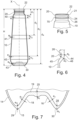
Figure 6 is a view in partial longitudinal cross section of the upper part of the container infigure 4 , and -
Figure 7 is a schematic view in longitudinal section of a lower part of the container infigure 4 . - The
pressurized bottle 1 shown in the figures has acontainer 3 containing the product to be dispensed, for example a cosmetic product to be sprayed, and adispensing system 2 mounted on thecontainer 3. - The
dispensing system 2 can be realized in various ways, being provided with an actuating member 4 (visible notably infigures 2 and 3 ) that the user can press in order to dispense the product through at least one outlet orifice, for example in the form of a spray. - The
dispensing system 2 has a dispensing head bearing the actuatingmember 4 and avalve 7 with a hollow control stem 9 to be controlled by being depressed or tilted, having acup 6 and shown schematically infigure 3 . - The product contained in the
container 3 leaves thevalve stem 9 when the latter is actuated, and then reaches the outlet orifice of the dispensing head through one or more internal ducts thereof. - The
container 3 has abody 10 formed as a single piece that extends along a longitudinal axis X and is extended at its upper end by aneck 20, theentire container 3 made up of thebody 10 and theneck 20 being made of thermoplastic material, for example PET. The formation of thecontainer 3 may include the blow molding of a preform within a mold, in a manner known per se. The thermoplastic material of which thecontainer 3 is made is for example transparent, at least in the region of thebody 10. - When not in use, the
neck 20 is at least partially concealed by a removableprotective cap 8, which is fastened to the container for example by snap-fastening. The neck of the bottle may be concealed by a cup of the bottle, which is fastened to the cup of the valve. - The
body 10 has a frustoconical shape over amajor part 11 of its height. Thelower part 14 of thebody 10 is rounded as far as alower end 30 of the container that is formed at the bottom 15 of thecontainer 3. - As can be seen in
figure 3 , the bottom 15 of thecontainer 3 has anindentation 16, of outwardly concave shape, defined by afrustoconical wall 18 that converges towards the inside of the container. - The
frustoconical wall 18 is attached to acrown 19 of theindentation 16, forming in this example a substantially flat wall, which bears at itscenter 25 the trace of the injection point of the preform used to produce thecontainer 3 by injection blow molding or compression blow molding. - The
container 3 has on its inside anannular groove 28 around thefrustoconical wall 18, in which the end of a dip tube connected to thedispensing system 2 can extend if need be, this tube not being shown infigure 3 . Thisannular groove 28 forms the, substantially circular,bottom line 29, which is in contact with the horizontal surface on which thebottle 1 stands when it is positioned vertically. Thisbottom line 29, which forms the, closed,lower end 30 of thecontainer 3, is referred to as the "standing line". - The
neck 20 of thecontainer 3 has an, open, upper end with anupper ring 21 that allows thedispensing system 2 to be attached and more particularly thecup 6 to be crimped. Theneck 20 also has alower ring 26, which can serve to transport the container along production and/or filling lines, and can be referred to as support ring or supporting lower ring. In this example, theneck 20 is crystallized over at least a part of its height, in the example illustrated as far as around 2 mm below the supportinglower ring 26. In a variant, theneck 20 is not crystallized. - The
upper ring 21 andlower ring 26 define agroove 70 between one another, the role of said groove being to allow the crimping pliers for thecup 6 to be fitted under theupper ring 21. - In the example illustrated, and as can be seen in
figure 4 , thecontainer 3 has a thickness e1 of at least 1.06 mm in a first portion 40 with a height h1 of 10 mm that is situated, starting from theupper end 22 of the neck, at a distance d1 of between 10% and 40% of the total height H of thecontainer 3. In the example illustrated, the height H, measured between theupper end 22 and thelower end 30, is equal to 131 mm. The distance d1 is equal to 20 mm, the first portion 40 therefore extending over a height ranging from 20 mm to 30 mm from theupper end 22. This minimum thickness e1 makes it possible, during the hot air test at 75°C, to avoid ejection of the aerosol valve. - The
container 3 furthermore has, at thelower end 30 of thebody 10, a minimum thickness e5 of 2 mm, at thebottom line 29, as can be seen infigure 7 . - These minimum thickness characteristics at these locations on the container make it possible to successfully undergo regulatory tests, notably those referred to as "hot air tests". In particular, the thickness e5 is chosen so as to make it possible to have a container bottom which does not deform in an asymmetric manner and thus to maintain a bottle that is stable and not tilted with respect to the vertical.
- The volume of the
container 3 in this example is 140 ml. - In the example illustrated, the
container 3 also has the following features. - The
container 3 has a thickness e2 of at least 0.55 mm in asecond portion 41 with a height h2 of 10 mm that is situated, starting from theupper end 22 of theneck 20, at a distance d2 of between 40% and 64% of the total height H of thecontainer 3, in this case at a distance d2 = 61 mm. This minimum thickness e2 makes it possible to have no problems during the vacuum test or during sleeve fitting, and possibly to avoid the deformation of the body of the container in the water bath test at 54°C. - The
container 3 has a thickness e3 of at least 0.55 mm in a third portion 42 with a height h2 of 10 mm that is situated, starting from theupper end 22 of theneck 20, at a distance d3 of between 65% and 91% of the total height H of thecontainer 3, in this case at a distance d3 = 103.5 mm. This makes it possible to successfully undergo the drop test and to avoid significant deformations during the passage through the water bath at 54°C. - The
container 3 has a thickness e4 of at least 0.7 mm in afourth portion 43 that is situated, starting from theupper end 22 of theneck 20, at a distance d4 of between 92% and 98% of the total height H of thecontainer 3. Thefourth portion 43 does not have a significant height and is limited substantially to a line, as illustrated. The distance d4 is equal to 126 mm in this example. This minimum thickness e4 makes it possible to avoid any breakage of the container during the drop test or any deformation in the water bath at 54°C. - Referring to
figure 7 , at thecenter 25 of thecrown 19 of theindentation 18, the thickness ee is at least 2.7 mm. The thickness e7 of thecontainer 3 halfway between thelower end 30 of thebody 10 and thecrown 19 of theindentation 18 is equal to at least 2 mm. It is important for the thickness e7 to be uniform around the circular perimeter of theindentation 18 in order to avoid asymmetric deformation of the container there. - In this example, the height h1, h2 and h3 of the first, second and third portions, respectively, is identical for each of the portions and equal to 10 mm. It would not constitute a departure from the scope of the invention if this height were lower or higher, being at least 8 mm, or if the heights of the portions were different from one another.
- The variation in thickness of the container within the first, second and third portions is at most 20% in this example. This is a tolerance that makes it possible to ensure that there is not excessive variation in thickness within one and the same portion.
- It should be noted that the first, second and third portions are situated mainly in the
part 11 with a substantially frustoconical shape. - As far as the
neck 20 is concerned, the thickness e8 thereof in aportion 44 parallel to the longitudinal axis X situated under thelower ring 26, as can be seen infigure 6 , is at least 2.9 mm. - Furthermore, the
neck 20 is joined to thebody 10 by ashoulder 45, the thickness e9 of the container at thejunction 46 between theneck 20 and theshoulder 45 being at least 2.4 mm. - The invention is not limited to the example which has just been described.
- In the following text, by way of nonlimiting indication, further values of distances di, d2, d3 and d4 for further containers with different volumes and total heights can be found, the heights hi, h2 and h3 remaining unchanged, as do the corresponding minimum thicknesses.
Container volume H d1 d2 d3 d4 110 ml 105.1 mm 20 mm 47 mm 77.6 mm 100.1 mm 210 ml 166.5 mm 20 mm 86.5 mm 139 mm 161.5 mm 110 ml 102.3 mm 20 mm 47 mm 74.8 mm 97.3 mm 210 ml 165.3 mm 20 mm 86.5 mm 137.8 mm 160.3 mm 210 ml 166.7 mm 20 mm 86.5 mm 139.2 mm 161.7 mm - The thickness e1 may be at least 0.9 mm, the thickness e2 may be at least 0.5 mm, the thickness e3 may be at least 0.5 mm, the thickness e4 may be at least 0.6 mm, the thickness e5 may be at least 1.4 mm, the thickness e6 may be at least 2.5 mm, the thickness e7 may be at least 1.8 mm, the thickness e8 may be at least 2.7 mm and the thickness e9 may be at least 2 mm, without departing from the scope of the invention.
- In a particular embodiment, the height h1 is equal to 6 mm and the heights h2 and h3 are equal to 10 mm.
Claims (15)
- A pressurized bottle (1) having a container (3) made of plastics material, comprising:- a body (10), formed as a single piece, that extends along a longitudinal axis (X) and has a lower end (30),- a neck (20) that is integral with the body (10) and has an upper end (22), the total height (H) of the container (3) being measured between the lower end (30) of the body (10) and the upper end (22) of the neck (20),wherein the container (3) has a thickness (e1) of at least 0.65 mm, preferably at least 0.9 mm, preferably between 0.65 mm and 1.13 mm, preferably between 0.9 mm and 1.13 mm, in a first portion (40) with a height (h1) of at least 6 mm, notably at least 8 mm, that is situated, starting from the upper end (22) of the neck (20), at a distance (d1) of between 10% and 40% of the total height (H) of the container (3), and in that the container (3) has, at the lower end (30) of the body, a thickness (e5) of at least 1.1 mm, notably at least 1.4 mm, preferably a thickness between 1.1 mm and 2 mm, preferably between 1.4 mm and 1.8 mm,characterized in that the neck (20) has two rings (21, 26) that define an annular groove (70) between one another, namely an upper ring (21) and a supporting lower ring (26), a thickness (e8) of the neck (20) in a portion substantially parallel to the longitudinal axis (X) situated under the lower ring (26) being at least 1.06 mm.
- The bottle (1) as claimed in claim 1, wherein the container (3) has a thickness (e2) of at least 0.4 mm, notably at least 0.5 mm or at least 0.6 mm, notably at least 0.65 mm, preferably between 0.4 mm and 0.8 mm, preferably between 0.6 mm and 0.8 mm, in a second portion (41) with a height (h2) of at least 8 mm that is situated, starting from the upper end (22) of the neck (20), at a distance (d2) of between 40% and 64% of the total height (H) of the container (3).
- The bottle (1) as claimed in either of the preceding claims, wherein the container (3) has a thickness (e3) of at least 0.4 mm , notably at least 0.5 mm, notably at least 0.55 mm or at least 0.6 mm, preferably between 0.4 mm and 0.69 mm, preferably between 0.55 mm and 0.69 mm, in a third portion (42) with a height (h3) of at least 8 mm that is situated, starting from the upper end (22) of the neck (20), at a distance (d3) of between 65% and 91% of the total height (H) of the container (3).
- The bottle (1) as claimed in any one of the preceding claims, wherein the container (3) has a thickness (e4) of at least 0.6 mm, notably at least 0.65 mm, notably at least 0.7 mm, preferably between 0.6 mm and 0.81 mm, preferably between 0.65 mm and 0.81 mm in a fourth portion (43) that is situated, starting from the upper end (22) of the neck (20), at a distance (d4) of between 92% and 98% of the total height (H) of the container (3).
- The bottle (1) as claimed in any one of the preceding claims, wherein the body (10) of the container (3) has a bottom (15) that is designed to allow the container (3) to stand on a horizontal flat surface, the bottom (15) comprising a downwardly concave indentation (18), the lower end (30) of the body extending around this indentation (18), notably following a bottom line (29) of circular contour that forms the lower end (30) of the body (10), wherein the concave indentation (18) has preferably a crown (19) at the center (25) of which the thickness (e6) is at least 2.5 mm, notably at least 2.7 mm, notably equal to 2.5 mm.
- The bottle (1) as claimed in claim 5, wherein a thickness (e7) of the container (3) halfway between the lower end (30) of the body (10) and the crown (19) of the indentation (18) is equal to at least 1.8 mm, notably to at least 2 mm, preferably between 1.8 mm and 2.5 mm.
- The bottle (1) as claimed in claims 2 and 3 or in any one of claims 4 to 6, when claims 4 to 6 depend on claims 2 and 3, wherein the height (h1) of the first portion (40), the height (h2) of the second portion (41) and/or the height (h3) of the third portion (42) is equal to 10 mm.
- The bottle (1) as claimed in claims 2 and 3 or in any one of claims 4 to 7, when claims 4 to 7 depend on claims 2 and 3, wherein said height (h1) of the first portion (40), said height (h2) of the second portion (41) and/or said height (h3) of the third portion (42) are identical.
- The bottle (1) as claimed in claims 2 and 3 or in any one of claims 4 to 8, when claims 4 to 8 depend on claims 2 and 3, wherein a variation in thickness of the container (3) within the first portion (40) or each of the first, second and/or third portions (40; 41; 42) is at most 20% to 40%.
- The bottle (1) as claimed in any one of the preceding claims, wherein the body (10) has a part (11) with a substantially frustoconical shape.
- The bottle (1) as claimed in the preceding claim and claim 2 and 3, wherein said first, second and third portions (40, 41, 42) are mainly situated in said part (11) with a substantially frustoconical shape.
- The bottle (1) as claimed in any one of the preceding claims, wherein the thickness (e8) of the neck (20) in the portion substantially parallel to the longitudinal axis (X) situated under the lower ring (26) is at least 2.7 mm, notably at least 2.9 mm, preferably between 1.06 mm and 2.9 mm.
- The bottle (1) as claimed in any one of the preceding claims, wherein the neck (20) is joined to the body (10) by a shoulder (45), the thickness (e9) of the container (3) at a junction (46) between the neck (20) and the shoulder (45) being at least 2 mm, notably at least 2.4 mm.
- The bottle (1) as claimed in any one of the preceding claims, wherein the neck (20) is at least partially crystallized.
- The bottle (1) as claimed in any one of the preceding claims, wherein the plastics material includes at least one polymer chosen from the group consisting of PET or PETP, PEN, PCT, recycled polymers, notably referred to as PCR polymers, in particular recycled PET, bioPET, PP, PE, PEF, PET-G/PCT-G, PET with glass fibers, PC, POM, SMMA, PMMA, SAN, PBT, PA6, PA12, PEEK, PPO, PSU, filled polymers, notably with mineral fillers and/or glass fibers, and mixtures thereof.
Applications Claiming Priority (2)
| Application Number | Priority Date | Filing Date | Title |
|---|---|---|---|
| FR1858130A FR3085671B1 (en) | 2018-09-11 | 2018-09-11 | PLASTIC AEROSOL BOTTLE |
| PCT/EP2019/074109 WO2020053210A1 (en) | 2018-09-11 | 2019-09-10 | Plastic aerosol bottle |
Publications (3)
| Publication Number | Publication Date |
|---|---|
| EP3849920A1 EP3849920A1 (en) | 2021-07-21 |
| EP3849920C0 EP3849920C0 (en) | 2024-03-20 |
| EP3849920B1 true EP3849920B1 (en) | 2024-03-20 |
Family
ID=65201364
Family Applications (1)
| Application Number | Title | Priority Date | Filing Date |
|---|---|---|---|
| EP19765729.9A Active EP3849920B1 (en) | 2018-09-11 | 2019-09-10 | Plastic aerosol bottle |
Country Status (6)
| Country | Link |
|---|---|
| EP (1) | EP3849920B1 (en) |
| JP (1) | JP7321274B2 (en) |
| KR (1) | KR102663373B1 (en) |
| ES (1) | ES2988926T3 (en) |
| FR (1) | FR3085671B1 (en) |
| WO (1) | WO2020053210A1 (en) |
Families Citing this family (2)
| Publication number | Priority date | Publication date | Assignee | Title |
|---|---|---|---|---|
| KR102516370B1 (en) * | 2020-05-14 | 2023-03-30 | 남경수 | Beverage container |
| US20250042172A1 (en) * | 2023-08-04 | 2025-02-06 | Canon Kabushiki Kaisha | Liquid storage bottle |
Citations (3)
| Publication number | Priority date | Publication date | Assignee | Title |
|---|---|---|---|---|
| WO1994001269A1 (en) | 1992-07-07 | 1994-01-20 | Continental Pet Technologies, Inc. | Method of forming container with high-crystallinity sidewall and low-clystallinity base |
| JPH07242222A (en) | 1994-02-28 | 1995-09-19 | Nissei Asb Mach Co Ltd | Pressure / heat resistant bottle |
| WO2017133996A1 (en) | 2016-02-02 | 2017-08-10 | L'oreal | Pressurized bottle made of plastics material |
Family Cites Families (9)
| Publication number | Priority date | Publication date | Assignee | Title |
|---|---|---|---|---|
| GB8917171D0 (en) * | 1989-07-27 | 1989-09-13 | Hoechst Celanese Plastics Ltd | Aerosol container top of plastics |
| US5083685A (en) * | 1990-06-28 | 1992-01-28 | Mitsui Toatsu Chemicals, Inc. | Vessel for aerosol |
| US5281387A (en) * | 1992-07-07 | 1994-01-25 | Continental Pet Technologies, Inc. | Method of forming a container having a low crystallinity |
| US5586695A (en) * | 1993-10-07 | 1996-12-24 | Labus; Rainer H. | Sprayed liquid dispensing apparatus |
| JP2002029581A (en) | 2000-07-14 | 2002-01-29 | Mandom Corp | Plastic container for aerosol product, and aerosol product using the same |
| JP2002037362A (en) | 2000-07-28 | 2002-02-06 | Daizo:Kk | Pressurized product |
| US7303087B2 (en) * | 2003-12-16 | 2007-12-04 | S. C. Johnson & Son, Inc. | Pressurized plastic bottle with reinforced neck and shoulder for dispensing an aerosol |
| WO2007140407A2 (en) * | 2006-05-31 | 2007-12-06 | The Clorox Company | Ergonomic plastic aerosol container |
| US20160264344A1 (en) * | 2011-07-08 | 2016-09-15 | S. C. Johnson & Son, Inc. | Stable Pressurized System Including Plastic Container And Active(s)-Containing Composition |
-
2018
- 2018-09-11 FR FR1858130A patent/FR3085671B1/en active Active
-
2019
- 2019-09-10 ES ES19765729T patent/ES2988926T3/en active Active
- 2019-09-10 KR KR1020217006717A patent/KR102663373B1/en active Active
- 2019-09-10 JP JP2021537504A patent/JP7321274B2/en active Active
- 2019-09-10 WO PCT/EP2019/074109 patent/WO2020053210A1/en not_active Ceased
- 2019-09-10 EP EP19765729.9A patent/EP3849920B1/en active Active
Patent Citations (3)
| Publication number | Priority date | Publication date | Assignee | Title |
|---|---|---|---|---|
| WO1994001269A1 (en) | 1992-07-07 | 1994-01-20 | Continental Pet Technologies, Inc. | Method of forming container with high-crystallinity sidewall and low-clystallinity base |
| JPH07242222A (en) | 1994-02-28 | 1995-09-19 | Nissei Asb Mach Co Ltd | Pressure / heat resistant bottle |
| WO2017133996A1 (en) | 2016-02-02 | 2017-08-10 | L'oreal | Pressurized bottle made of plastics material |
Also Published As
| Publication number | Publication date |
|---|---|
| ES2988926T3 (en) | 2024-11-22 |
| KR20210041043A (en) | 2021-04-14 |
| JP2022511989A (en) | 2022-02-01 |
| EP3849920C0 (en) | 2024-03-20 |
| FR3085671A1 (en) | 2020-03-13 |
| JP7321274B2 (en) | 2023-08-04 |
| EP3849920A1 (en) | 2021-07-21 |
| FR3085671B1 (en) | 2022-07-29 |
| WO2020053210A1 (en) | 2020-03-19 |
| KR102663373B1 (en) | 2024-05-03 |
Similar Documents
| Publication | Publication Date | Title |
|---|---|---|
| CN109476414B (en) | Aerosol Dispenser | |
| JP2619688B2 (en) | Blow molding preform and blow molding method using the same | |
| JP6110511B2 (en) | Self-foldable blow molded plastic thin container | |
| CN110225867B (en) | Plastic bottle for pressurized dispensing systems | |
| US5772056A (en) | Plastic blow molded container | |
| EP3375593B1 (en) | Method for forming a container with a plastic liner and fibre-based shell by blow molding, preform and container | |
| EP2355969B1 (en) | Method of making plastic container having a deep-inset base | |
| CA2766426A1 (en) | Panelless hot-fill plastic bottle | |
| EP3849920B1 (en) | Plastic aerosol bottle | |
| CN116062276B (en) | Mold bottom for manufacturing a container comprising an arched bottom with reinforcing protrusions | |
| US9290280B2 (en) | Method for producing a container intended to contain a substance to be dispensed by an airless pump, and a container produced by the method | |
| EP3257768A1 (en) | Container provided with a convex invertible diaphragm | |
| WO2017133996A1 (en) | Pressurized bottle made of plastics material | |
| US20070045221A1 (en) | Plastic container having a ring-shaped reinforcement and method of making same | |
| US10486892B1 (en) | Packages and arrays of packages for plastic aerosol dispensers | |
| US12390969B2 (en) | Method for manufacturing an injection-molded article, in particular a bottle preform | |
| CH711621A1 (en) | Preform for producing a plastic container in a stretch blow molding process. | |
| US11453154B2 (en) | Method of manufacturing liquid container | |
| CN111315552A (en) | Aerosol dispenser, polygonal crimp ring outer container therefor, and preform therefor |
Legal Events
| Date | Code | Title | Description |
|---|---|---|---|
| STAA | Information on the status of an ep patent application or granted ep patent |
Free format text: STATUS: UNKNOWN |
|
| STAA | Information on the status of an ep patent application or granted ep patent |
Free format text: STATUS: THE INTERNATIONAL PUBLICATION HAS BEEN MADE |
|
| PUAI | Public reference made under article 153(3) epc to a published international application that has entered the european phase |
Free format text: ORIGINAL CODE: 0009012 |
|
| STAA | Information on the status of an ep patent application or granted ep patent |
Free format text: STATUS: REQUEST FOR EXAMINATION WAS MADE |
|
| 17P | Request for examination filed |
Effective date: 20210308 |
|
| AK | Designated contracting states |
Kind code of ref document: A1 Designated state(s): AL AT BE BG CH CY CZ DE DK EE ES FI FR GB GR HR HU IE IS IT LI LT LU LV MC MK MT NL NO PL PT RO RS SE SI SK SM TR |
|
| DAV | Request for validation of the european patent (deleted) | ||
| DAX | Request for extension of the european patent (deleted) | ||
| STAA | Information on the status of an ep patent application or granted ep patent |
Free format text: STATUS: EXAMINATION IS IN PROGRESS |
|
| 17Q | First examination report despatched |
Effective date: 20221221 |
|
| RAP3 | Party data changed (applicant data changed or rights of an application transferred) |
Owner name: L'OREAL |
|
| GRAP | Despatch of communication of intention to grant a patent |
Free format text: ORIGINAL CODE: EPIDOSNIGR1 |
|
| STAA | Information on the status of an ep patent application or granted ep patent |
Free format text: STATUS: GRANT OF PATENT IS INTENDED |
|
| RIC1 | Information provided on ipc code assigned before grant |
Ipc: B29L 31/00 20060101ALN20231127BHEP Ipc: B65D 1/02 20060101ALI20231127BHEP Ipc: B65D 83/38 20060101AFI20231127BHEP |
|
| INTG | Intention to grant announced |
Effective date: 20231211 |
|
| GRAS | Grant fee paid |
Free format text: ORIGINAL CODE: EPIDOSNIGR3 |
|
| GRAA | (expected) grant |
Free format text: ORIGINAL CODE: 0009210 |
|
| STAA | Information on the status of an ep patent application or granted ep patent |
Free format text: STATUS: THE PATENT HAS BEEN GRANTED |
|
| AK | Designated contracting states |
Kind code of ref document: B1 Designated state(s): AL AT BE BG CH CY CZ DE DK EE ES FI FR GB GR HR HU IE IS IT LI LT LU LV MC MK MT NL NO PL PT RO RS SE SI SK SM TR |
|
| REG | Reference to a national code |
Ref country code: GB Ref legal event code: FG4D |
|
| REG | Reference to a national code |
Ref country code: CH Ref legal event code: EP |
|
| REG | Reference to a national code |
Ref country code: IE Ref legal event code: FG4D |
|
| REG | Reference to a national code |
Ref country code: DE Ref legal event code: R096 Ref document number: 602019048636 Country of ref document: DE |
|
| U01 | Request for unitary effect filed |
Effective date: 20240418 |
|
| U07 | Unitary effect registered |
Designated state(s): AT BE BG DE DK EE FI FR IT LT LU LV MT NL PT SE SI Effective date: 20240424 |
|
| PG25 | Lapsed in a contracting state [announced via postgrant information from national office to epo] |
Ref country code: GR Free format text: LAPSE BECAUSE OF FAILURE TO SUBMIT A TRANSLATION OF THE DESCRIPTION OR TO PAY THE FEE WITHIN THE PRESCRIBED TIME-LIMIT Effective date: 20240621 |
|
| PG25 | Lapsed in a contracting state [announced via postgrant information from national office to epo] |
Ref country code: RS Free format text: LAPSE BECAUSE OF FAILURE TO SUBMIT A TRANSLATION OF THE DESCRIPTION OR TO PAY THE FEE WITHIN THE PRESCRIBED TIME-LIMIT Effective date: 20240620 Ref country code: HR Free format text: LAPSE BECAUSE OF FAILURE TO SUBMIT A TRANSLATION OF THE DESCRIPTION OR TO PAY THE FEE WITHIN THE PRESCRIBED TIME-LIMIT Effective date: 20240320 |
|
| PG25 | Lapsed in a contracting state [announced via postgrant information from national office to epo] |
Ref country code: RS Free format text: LAPSE BECAUSE OF FAILURE TO SUBMIT A TRANSLATION OF THE DESCRIPTION OR TO PAY THE FEE WITHIN THE PRESCRIBED TIME-LIMIT Effective date: 20240620 Ref country code: NO Free format text: LAPSE BECAUSE OF FAILURE TO SUBMIT A TRANSLATION OF THE DESCRIPTION OR TO PAY THE FEE WITHIN THE PRESCRIBED TIME-LIMIT Effective date: 20240620 Ref country code: HR Free format text: LAPSE BECAUSE OF FAILURE TO SUBMIT A TRANSLATION OF THE DESCRIPTION OR TO PAY THE FEE WITHIN THE PRESCRIBED TIME-LIMIT Effective date: 20240320 Ref country code: GR Free format text: LAPSE BECAUSE OF FAILURE TO SUBMIT A TRANSLATION OF THE DESCRIPTION OR TO PAY THE FEE WITHIN THE PRESCRIBED TIME-LIMIT Effective date: 20240621 |
|
| U20 | Renewal fee for the european patent with unitary effect paid |
Year of fee payment: 6 Effective date: 20240807 |
|
| PG25 | Lapsed in a contracting state [announced via postgrant information from national office to epo] |
Ref country code: IS Free format text: LAPSE BECAUSE OF FAILURE TO SUBMIT A TRANSLATION OF THE DESCRIPTION OR TO PAY THE FEE WITHIN THE PRESCRIBED TIME-LIMIT Effective date: 20240720 |
|
| PG25 | Lapsed in a contracting state [announced via postgrant information from national office to epo] |
Ref country code: SM Free format text: LAPSE BECAUSE OF FAILURE TO SUBMIT A TRANSLATION OF THE DESCRIPTION OR TO PAY THE FEE WITHIN THE PRESCRIBED TIME-LIMIT Effective date: 20240320 |
|
| PG25 | Lapsed in a contracting state [announced via postgrant information from national office to epo] |
Ref country code: CZ Free format text: LAPSE BECAUSE OF FAILURE TO SUBMIT A TRANSLATION OF THE DESCRIPTION OR TO PAY THE FEE WITHIN THE PRESCRIBED TIME-LIMIT Effective date: 20240320 |
|
| PG25 | Lapsed in a contracting state [announced via postgrant information from national office to epo] |
Ref country code: PL Free format text: LAPSE BECAUSE OF FAILURE TO SUBMIT A TRANSLATION OF THE DESCRIPTION OR TO PAY THE FEE WITHIN THE PRESCRIBED TIME-LIMIT Effective date: 20240320 |
|
| PG25 | Lapsed in a contracting state [announced via postgrant information from national office to epo] |
Ref country code: SK Free format text: LAPSE BECAUSE OF FAILURE TO SUBMIT A TRANSLATION OF THE DESCRIPTION OR TO PAY THE FEE WITHIN THE PRESCRIBED TIME-LIMIT Effective date: 20240320 |
|
| PG25 | Lapsed in a contracting state [announced via postgrant information from national office to epo] |
Ref country code: SM Free format text: LAPSE BECAUSE OF FAILURE TO SUBMIT A TRANSLATION OF THE DESCRIPTION OR TO PAY THE FEE WITHIN THE PRESCRIBED TIME-LIMIT Effective date: 20240320 Ref country code: SK Free format text: LAPSE BECAUSE OF FAILURE TO SUBMIT A TRANSLATION OF THE DESCRIPTION OR TO PAY THE FEE WITHIN THE PRESCRIBED TIME-LIMIT Effective date: 20240320 Ref country code: RO Free format text: LAPSE BECAUSE OF FAILURE TO SUBMIT A TRANSLATION OF THE DESCRIPTION OR TO PAY THE FEE WITHIN THE PRESCRIBED TIME-LIMIT Effective date: 20240320 Ref country code: PL Free format text: LAPSE BECAUSE OF FAILURE TO SUBMIT A TRANSLATION OF THE DESCRIPTION OR TO PAY THE FEE WITHIN THE PRESCRIBED TIME-LIMIT Effective date: 20240320 Ref country code: IS Free format text: LAPSE BECAUSE OF FAILURE TO SUBMIT A TRANSLATION OF THE DESCRIPTION OR TO PAY THE FEE WITHIN THE PRESCRIBED TIME-LIMIT Effective date: 20240720 Ref country code: CZ Free format text: LAPSE BECAUSE OF FAILURE TO SUBMIT A TRANSLATION OF THE DESCRIPTION OR TO PAY THE FEE WITHIN THE PRESCRIBED TIME-LIMIT Effective date: 20240320 |
|
| REG | Reference to a national code |
Ref country code: ES Ref legal event code: FG2A Ref document number: 2988926 Country of ref document: ES Kind code of ref document: T3 Effective date: 20241122 |
|
| REG | Reference to a national code |
Ref country code: DE Ref legal event code: R026 Ref document number: 602019048636 Country of ref document: DE |
|
| PLBI | Opposition filed |
Free format text: ORIGINAL CODE: 0009260 |
|
| PLAB | Opposition data, opponent's data or that of the opponent's representative modified |
Free format text: ORIGINAL CODE: 0009299OPPO |
|
| PLAX | Notice of opposition and request to file observation + time limit sent |
Free format text: ORIGINAL CODE: EPIDOSNOBS2 |
|
| 26 | Opposition filed |
Opponent name: ALPLA WERKE ALWIN LEHNER GMBH & CO KG Effective date: 20241220 |
|
| R26 | Opposition filed (corrected) |
Opponent name: ALPLA WERKE ALWIN LEHNER GMBH & CO KG Effective date: 20241220 |
|
| PG25 | Lapsed in a contracting state [announced via postgrant information from national office to epo] |
Ref country code: MC Free format text: LAPSE BECAUSE OF FAILURE TO SUBMIT A TRANSLATION OF THE DESCRIPTION OR TO PAY THE FEE WITHIN THE PRESCRIBED TIME-LIMIT Effective date: 20240320 |
|
| REG | Reference to a national code |
Ref country code: CH Ref legal event code: PL |
|
| PLBB | Reply of patent proprietor to notice(s) of opposition received |
Free format text: ORIGINAL CODE: EPIDOSNOBS3 |
|
| PG25 | Lapsed in a contracting state [announced via postgrant information from national office to epo] |
Ref country code: CH Free format text: LAPSE BECAUSE OF NON-PAYMENT OF DUE FEES Effective date: 20240930 |
|
| PG25 | Lapsed in a contracting state [announced via postgrant information from national office to epo] |
Ref country code: IE Free format text: LAPSE BECAUSE OF NON-PAYMENT OF DUE FEES Effective date: 20240910 |
|
| U20 | Renewal fee for the european patent with unitary effect paid |
Year of fee payment: 7 Effective date: 20250807 |
|
| U1N | Appointed representative for the unitary patent procedure changed after the registration of the unitary effect |
Representative=s name: IPSILON; FR |
|
| PGFP | Annual fee paid to national office [announced via postgrant information from national office to epo] |
Ref country code: GB Payment date: 20250703 Year of fee payment: 7 |
|
| PG25 | Lapsed in a contracting state [announced via postgrant information from national office to epo] |
Ref country code: CY Free format text: LAPSE BECAUSE OF FAILURE TO SUBMIT A TRANSLATION OF THE DESCRIPTION OR TO PAY THE FEE WITHIN THE PRESCRIBED TIME-LIMIT; INVALID AB INITIO Effective date: 20190910 |
|
| PGFP | Annual fee paid to national office [announced via postgrant information from national office to epo] |
Ref country code: ES Payment date: 20251015 Year of fee payment: 7 |
|
| PG25 | Lapsed in a contracting state [announced via postgrant information from national office to epo] |
Ref country code: HU Free format text: LAPSE BECAUSE OF FAILURE TO SUBMIT A TRANSLATION OF THE DESCRIPTION OR TO PAY THE FEE WITHIN THE PRESCRIBED TIME-LIMIT; INVALID AB INITIO Effective date: 20190910 |