EP3849784B1 - Positioning profiles for pultrusions in wind blade spar caps - Google Patents
Positioning profiles for pultrusions in wind blade spar caps Download PDFInfo
- Publication number
- EP3849784B1 EP3849784B1 EP18933064.0A EP18933064A EP3849784B1 EP 3849784 B1 EP3849784 B1 EP 3849784B1 EP 18933064 A EP18933064 A EP 18933064A EP 3849784 B1 EP3849784 B1 EP 3849784B1
- Authority
- EP
- European Patent Office
- Prior art keywords
- spar cap
- feature
- locating
- shear web
- bond gap
- Prior art date
- Legal status (The legal status is an assumption and is not a legal conclusion. Google has not performed a legal analysis and makes no representation as to the accuracy of the status listed.)
- Active
Links
Images






Classifications
-
- F—MECHANICAL ENGINEERING; LIGHTING; HEATING; WEAPONS; BLASTING
- F03—MACHINES OR ENGINES FOR LIQUIDS; WIND, SPRING, OR WEIGHT MOTORS; PRODUCING MECHANICAL POWER OR A REACTIVE PROPULSIVE THRUST, NOT OTHERWISE PROVIDED FOR
- F03D—WIND MOTORS
- F03D13/00—Assembly, mounting or commissioning of wind motors; Arrangements specially adapted for transporting wind motor components
- F03D13/10—Assembly of wind motors; Arrangements for erecting wind motors
-
- B—PERFORMING OPERATIONS; TRANSPORTING
- B29—WORKING OF PLASTICS; WORKING OF SUBSTANCES IN A PLASTIC STATE IN GENERAL
- B29C—SHAPING OR JOINING OF PLASTICS; SHAPING OF MATERIAL IN A PLASTIC STATE, NOT OTHERWISE PROVIDED FOR; AFTER-TREATMENT OF THE SHAPED PRODUCTS, e.g. REPAIRING
- B29C65/00—Joining or sealing of preformed parts, e.g. welding of plastics materials; Apparatus therefor
- B29C65/48—Joining or sealing of preformed parts, e.g. welding of plastics materials; Apparatus therefor using adhesives, i.e. using supplementary joining material; solvent bonding
-
- B—PERFORMING OPERATIONS; TRANSPORTING
- B29—WORKING OF PLASTICS; WORKING OF SUBSTANCES IN A PLASTIC STATE IN GENERAL
- B29C—SHAPING OR JOINING OF PLASTICS; SHAPING OF MATERIAL IN A PLASTIC STATE, NOT OTHERWISE PROVIDED FOR; AFTER-TREATMENT OF THE SHAPED PRODUCTS, e.g. REPAIRING
- B29C65/00—Joining or sealing of preformed parts, e.g. welding of plastics materials; Apparatus therefor
- B29C65/78—Means for handling the parts to be joined, e.g. for making containers or hollow articles, e.g. means for handling sheets, plates, web-like materials, tubular articles, hollow articles or elements to be joined therewith; Means for discharging the joined articles from the joining apparatus
- B29C65/7802—Positioning the parts to be joined, e.g. aligning, indexing or centring
- B29C65/7805—Positioning the parts to be joined, e.g. aligning, indexing or centring the parts to be joined comprising positioning features
- B29C65/7814—Positioning the parts to be joined, e.g. aligning, indexing or centring the parts to be joined comprising positioning features in the form of inter-cooperating positioning features, e.g. tenons and mortises
-
- B—PERFORMING OPERATIONS; TRANSPORTING
- B29—WORKING OF PLASTICS; WORKING OF SUBSTANCES IN A PLASTIC STATE IN GENERAL
- B29C—SHAPING OR JOINING OF PLASTICS; SHAPING OF MATERIAL IN A PLASTIC STATE, NOT OTHERWISE PROVIDED FOR; AFTER-TREATMENT OF THE SHAPED PRODUCTS, e.g. REPAIRING
- B29C65/00—Joining or sealing of preformed parts, e.g. welding of plastics materials; Apparatus therefor
- B29C65/78—Means for handling the parts to be joined, e.g. for making containers or hollow articles, e.g. means for handling sheets, plates, web-like materials, tubular articles, hollow articles or elements to be joined therewith; Means for discharging the joined articles from the joining apparatus
- B29C65/7802—Positioning the parts to be joined, e.g. aligning, indexing or centring
- B29C65/782—Positioning the parts to be joined, e.g. aligning, indexing or centring by setting the gap between the parts to be joined
- B29C65/7823—Positioning the parts to be joined, e.g. aligning, indexing or centring by setting the gap between the parts to be joined by using distance pieces, i.e. by using spacers positioned between the parts to be joined and forming a part of the joint
- B29C65/7829—Positioning the parts to be joined, e.g. aligning, indexing or centring by setting the gap between the parts to be joined by using distance pieces, i.e. by using spacers positioned between the parts to be joined and forming a part of the joint said distance pieces being integral with at least one of the parts to be joined
-
- B—PERFORMING OPERATIONS; TRANSPORTING
- B29—WORKING OF PLASTICS; WORKING OF SUBSTANCES IN A PLASTIC STATE IN GENERAL
- B29C—SHAPING OR JOINING OF PLASTICS; SHAPING OF MATERIAL IN A PLASTIC STATE, NOT OTHERWISE PROVIDED FOR; AFTER-TREATMENT OF THE SHAPED PRODUCTS, e.g. REPAIRING
- B29C66/00—General aspects of processes or apparatus for joining preformed parts
- B29C66/01—General aspects dealing with the joint area or with the area to be joined
- B29C66/05—Particular design of joint configurations
- B29C66/10—Particular design of joint configurations particular design of the joint cross-sections
- B29C66/11—Joint cross-sections comprising a single joint-segment, i.e. one of the parts to be joined comprising a single joint-segment in the joint cross-section
- B29C66/114—Single butt joints
- B29C66/1142—Single butt to butt joints
-
- B—PERFORMING OPERATIONS; TRANSPORTING
- B29—WORKING OF PLASTICS; WORKING OF SUBSTANCES IN A PLASTIC STATE IN GENERAL
- B29C—SHAPING OR JOINING OF PLASTICS; SHAPING OF MATERIAL IN A PLASTIC STATE, NOT OTHERWISE PROVIDED FOR; AFTER-TREATMENT OF THE SHAPED PRODUCTS, e.g. REPAIRING
- B29C66/00—General aspects of processes or apparatus for joining preformed parts
- B29C66/01—General aspects dealing with the joint area or with the area to be joined
- B29C66/05—Particular design of joint configurations
- B29C66/10—Particular design of joint configurations particular design of the joint cross-sections
- B29C66/13—Single flanged joints; Fin-type joints; Single hem joints; Edge joints; Interpenetrating fingered joints; Other specific particular designs of joint cross-sections not provided for in groups B29C66/11 - B29C66/12
- B29C66/131—Single flanged joints, i.e. one of the parts to be joined being rigid and flanged in the joint area
-
- B—PERFORMING OPERATIONS; TRANSPORTING
- B29—WORKING OF PLASTICS; WORKING OF SUBSTANCES IN A PLASTIC STATE IN GENERAL
- B29C—SHAPING OR JOINING OF PLASTICS; SHAPING OF MATERIAL IN A PLASTIC STATE, NOT OTHERWISE PROVIDED FOR; AFTER-TREATMENT OF THE SHAPED PRODUCTS, e.g. REPAIRING
- B29C66/00—General aspects of processes or apparatus for joining preformed parts
- B29C66/01—General aspects dealing with the joint area or with the area to be joined
- B29C66/32—Measures for keeping the burr form under control; Avoiding burr formation; Shaping the burr
- B29C66/322—Providing cavities in the joined article to collect the burr
-
- B—PERFORMING OPERATIONS; TRANSPORTING
- B29—WORKING OF PLASTICS; WORKING OF SUBSTANCES IN A PLASTIC STATE IN GENERAL
- B29C—SHAPING OR JOINING OF PLASTICS; SHAPING OF MATERIAL IN A PLASTIC STATE, NOT OTHERWISE PROVIDED FOR; AFTER-TREATMENT OF THE SHAPED PRODUCTS, e.g. REPAIRING
- B29C66/00—General aspects of processes or apparatus for joining preformed parts
- B29C66/50—General aspects of joining tubular articles; General aspects of joining long products, i.e. bars or profiled elements; General aspects of joining single elements to tubular articles, hollow articles or bars; General aspects of joining several hollow-preforms to form hollow or tubular articles
- B29C66/51—Joining tubular articles, profiled elements or bars; Joining single elements to tubular articles, hollow articles or bars; Joining several hollow-preforms to form hollow or tubular articles
- B29C66/52—Joining tubular articles, bars or profiled elements
- B29C66/524—Joining profiled elements
-
- B—PERFORMING OPERATIONS; TRANSPORTING
- B29—WORKING OF PLASTICS; WORKING OF SUBSTANCES IN A PLASTIC STATE IN GENERAL
- B29C—SHAPING OR JOINING OF PLASTICS; SHAPING OF MATERIAL IN A PLASTIC STATE, NOT OTHERWISE PROVIDED FOR; AFTER-TREATMENT OF THE SHAPED PRODUCTS, e.g. REPAIRING
- B29C66/00—General aspects of processes or apparatus for joining preformed parts
- B29C66/50—General aspects of joining tubular articles; General aspects of joining long products, i.e. bars or profiled elements; General aspects of joining single elements to tubular articles, hollow articles or bars; General aspects of joining several hollow-preforms to form hollow or tubular articles
- B29C66/51—Joining tubular articles, profiled elements or bars; Joining single elements to tubular articles, hollow articles or bars; Joining several hollow-preforms to form hollow or tubular articles
- B29C66/53—Joining single elements to tubular articles, hollow articles or bars
- B29C66/532—Joining single elements to the wall of tubular articles, hollow articles or bars
-
- B—PERFORMING OPERATIONS; TRANSPORTING
- B29—WORKING OF PLASTICS; WORKING OF SUBSTANCES IN A PLASTIC STATE IN GENERAL
- B29C—SHAPING OR JOINING OF PLASTICS; SHAPING OF MATERIAL IN A PLASTIC STATE, NOT OTHERWISE PROVIDED FOR; AFTER-TREATMENT OF THE SHAPED PRODUCTS, e.g. REPAIRING
- B29C66/00—General aspects of processes or apparatus for joining preformed parts
- B29C66/50—General aspects of joining tubular articles; General aspects of joining long products, i.e. bars or profiled elements; General aspects of joining single elements to tubular articles, hollow articles or bars; General aspects of joining several hollow-preforms to form hollow or tubular articles
- B29C66/51—Joining tubular articles, profiled elements or bars; Joining single elements to tubular articles, hollow articles or bars; Joining several hollow-preforms to form hollow or tubular articles
- B29C66/54—Joining several hollow-preforms, e.g. half-shells, to form hollow articles, e.g. for making balls, containers; Joining several hollow-preforms, e.g. half-cylinders, to form tubular articles
-
- B—PERFORMING OPERATIONS; TRANSPORTING
- B29—WORKING OF PLASTICS; WORKING OF SUBSTANCES IN A PLASTIC STATE IN GENERAL
- B29C—SHAPING OR JOINING OF PLASTICS; SHAPING OF MATERIAL IN A PLASTIC STATE, NOT OTHERWISE PROVIDED FOR; AFTER-TREATMENT OF THE SHAPED PRODUCTS, e.g. REPAIRING
- B29C66/00—General aspects of processes or apparatus for joining preformed parts
- B29C66/50—General aspects of joining tubular articles; General aspects of joining long products, i.e. bars or profiled elements; General aspects of joining single elements to tubular articles, hollow articles or bars; General aspects of joining several hollow-preforms to form hollow or tubular articles
- B29C66/51—Joining tubular articles, profiled elements or bars; Joining single elements to tubular articles, hollow articles or bars; Joining several hollow-preforms to form hollow or tubular articles
- B29C66/54—Joining several hollow-preforms, e.g. half-shells, to form hollow articles, e.g. for making balls, containers; Joining several hollow-preforms, e.g. half-cylinders, to form tubular articles
- B29C66/543—Joining several hollow-preforms, e.g. half-shells, to form hollow articles, e.g. for making balls, containers; Joining several hollow-preforms, e.g. half-cylinders, to form tubular articles joining more than two hollow-preforms to form said hollow articles
-
- B—PERFORMING OPERATIONS; TRANSPORTING
- B29—WORKING OF PLASTICS; WORKING OF SUBSTANCES IN A PLASTIC STATE IN GENERAL
- B29C—SHAPING OR JOINING OF PLASTICS; SHAPING OF MATERIAL IN A PLASTIC STATE, NOT OTHERWISE PROVIDED FOR; AFTER-TREATMENT OF THE SHAPED PRODUCTS, e.g. REPAIRING
- B29C66/00—General aspects of processes or apparatus for joining preformed parts
- B29C66/50—General aspects of joining tubular articles; General aspects of joining long products, i.e. bars or profiled elements; General aspects of joining single elements to tubular articles, hollow articles or bars; General aspects of joining several hollow-preforms to form hollow or tubular articles
- B29C66/61—Joining from or joining on the inside
-
- B—PERFORMING OPERATIONS; TRANSPORTING
- B29—WORKING OF PLASTICS; WORKING OF SUBSTANCES IN A PLASTIC STATE IN GENERAL
- B29C—SHAPING OR JOINING OF PLASTICS; SHAPING OF MATERIAL IN A PLASTIC STATE, NOT OTHERWISE PROVIDED FOR; AFTER-TREATMENT OF THE SHAPED PRODUCTS, e.g. REPAIRING
- B29C66/00—General aspects of processes or apparatus for joining preformed parts
- B29C66/50—General aspects of joining tubular articles; General aspects of joining long products, i.e. bars or profiled elements; General aspects of joining single elements to tubular articles, hollow articles or bars; General aspects of joining several hollow-preforms to form hollow or tubular articles
- B29C66/63—Internally supporting the article during joining
- B29C66/636—Internally supporting the article during joining using a support which remains in the joined object
-
- B—PERFORMING OPERATIONS; TRANSPORTING
- B29—WORKING OF PLASTICS; WORKING OF SUBSTANCES IN A PLASTIC STATE IN GENERAL
- B29C—SHAPING OR JOINING OF PLASTICS; SHAPING OF MATERIAL IN A PLASTIC STATE, NOT OTHERWISE PROVIDED FOR; AFTER-TREATMENT OF THE SHAPED PRODUCTS, e.g. REPAIRING
- B29C66/00—General aspects of processes or apparatus for joining preformed parts
- B29C66/70—General aspects of processes or apparatus for joining preformed parts characterised by the composition, physical properties or the structure of the material of the parts to be joined; Joining with non-plastics material
- B29C66/72—General aspects of processes or apparatus for joining preformed parts characterised by the composition, physical properties or the structure of the material of the parts to be joined; Joining with non-plastics material characterised by the structure of the material of the parts to be joined
- B29C66/721—Fibre-reinforced materials
-
- B—PERFORMING OPERATIONS; TRANSPORTING
- B29—WORKING OF PLASTICS; WORKING OF SUBSTANCES IN A PLASTIC STATE IN GENERAL
- B29C—SHAPING OR JOINING OF PLASTICS; SHAPING OF MATERIAL IN A PLASTIC STATE, NOT OTHERWISE PROVIDED FOR; AFTER-TREATMENT OF THE SHAPED PRODUCTS, e.g. REPAIRING
- B29C66/00—General aspects of processes or apparatus for joining preformed parts
- B29C66/70—General aspects of processes or apparatus for joining preformed parts characterised by the composition, physical properties or the structure of the material of the parts to be joined; Joining with non-plastics material
- B29C66/72—General aspects of processes or apparatus for joining preformed parts characterised by the composition, physical properties or the structure of the material of the parts to be joined; Joining with non-plastics material characterised by the structure of the material of the parts to be joined
- B29C66/721—Fibre-reinforced materials
- B29C66/7214—Fibre-reinforced materials characterised by the length of the fibres
- B29C66/72141—Fibres of continuous length
-
- B—PERFORMING OPERATIONS; TRANSPORTING
- B29—WORKING OF PLASTICS; WORKING OF SUBSTANCES IN A PLASTIC STATE IN GENERAL
- B29C—SHAPING OR JOINING OF PLASTICS; SHAPING OF MATERIAL IN A PLASTIC STATE, NOT OTHERWISE PROVIDED FOR; AFTER-TREATMENT OF THE SHAPED PRODUCTS, e.g. REPAIRING
- B29C66/00—General aspects of processes or apparatus for joining preformed parts
- B29C66/70—General aspects of processes or apparatus for joining preformed parts characterised by the composition, physical properties or the structure of the material of the parts to be joined; Joining with non-plastics material
- B29C66/73—General aspects of processes or apparatus for joining preformed parts characterised by the composition, physical properties or the structure of the material of the parts to be joined; Joining with non-plastics material characterised by the intensive physical properties of the material of the parts to be joined, by the optical properties of the material of the parts to be joined, by the extensive physical properties of the parts to be joined, by the state of the material of the parts to be joined or by the material of the parts to be joined being a thermoplastic or a thermoset
- B29C66/737—General aspects of processes or apparatus for joining preformed parts characterised by the composition, physical properties or the structure of the material of the parts to be joined; Joining with non-plastics material characterised by the intensive physical properties of the material of the parts to be joined, by the optical properties of the material of the parts to be joined, by the extensive physical properties of the parts to be joined, by the state of the material of the parts to be joined or by the material of the parts to be joined being a thermoplastic or a thermoset characterised by the state of the material of the parts to be joined
- B29C66/7375—General aspects of processes or apparatus for joining preformed parts characterised by the composition, physical properties or the structure of the material of the parts to be joined; Joining with non-plastics material characterised by the intensive physical properties of the material of the parts to be joined, by the optical properties of the material of the parts to be joined, by the extensive physical properties of the parts to be joined, by the state of the material of the parts to be joined or by the material of the parts to be joined being a thermoplastic or a thermoset characterised by the state of the material of the parts to be joined uncured, partially cured or fully cured
- B29C66/73755—General aspects of processes or apparatus for joining preformed parts characterised by the composition, physical properties or the structure of the material of the parts to be joined; Joining with non-plastics material characterised by the intensive physical properties of the material of the parts to be joined, by the optical properties of the material of the parts to be joined, by the extensive physical properties of the parts to be joined, by the state of the material of the parts to be joined or by the material of the parts to be joined being a thermoplastic or a thermoset characterised by the state of the material of the parts to be joined uncured, partially cured or fully cured the to-be-joined area of at least one of the parts to be joined being fully cured, i.e. fully cross-linked, fully vulcanized
- B29C66/73756—General aspects of processes or apparatus for joining preformed parts characterised by the composition, physical properties or the structure of the material of the parts to be joined; Joining with non-plastics material characterised by the intensive physical properties of the material of the parts to be joined, by the optical properties of the material of the parts to be joined, by the extensive physical properties of the parts to be joined, by the state of the material of the parts to be joined or by the material of the parts to be joined being a thermoplastic or a thermoset characterised by the state of the material of the parts to be joined uncured, partially cured or fully cured the to-be-joined area of at least one of the parts to be joined being fully cured, i.e. fully cross-linked, fully vulcanized the to-be-joined areas of both parts to be joined being fully cured
-
- B—PERFORMING OPERATIONS; TRANSPORTING
- B29—WORKING OF PLASTICS; WORKING OF SUBSTANCES IN A PLASTIC STATE IN GENERAL
- B29C—SHAPING OR JOINING OF PLASTICS; SHAPING OF MATERIAL IN A PLASTIC STATE, NOT OTHERWISE PROVIDED FOR; AFTER-TREATMENT OF THE SHAPED PRODUCTS, e.g. REPAIRING
- B29C66/00—General aspects of processes or apparatus for joining preformed parts
- B29C66/70—General aspects of processes or apparatus for joining preformed parts characterised by the composition, physical properties or the structure of the material of the parts to be joined; Joining with non-plastics material
- B29C66/73—General aspects of processes or apparatus for joining preformed parts characterised by the composition, physical properties or the structure of the material of the parts to be joined; Joining with non-plastics material characterised by the intensive physical properties of the material of the parts to be joined, by the optical properties of the material of the parts to be joined, by the extensive physical properties of the parts to be joined, by the state of the material of the parts to be joined or by the material of the parts to be joined being a thermoplastic or a thermoset
- B29C66/739—General aspects of processes or apparatus for joining preformed parts characterised by the composition, physical properties or the structure of the material of the parts to be joined; Joining with non-plastics material characterised by the intensive physical properties of the material of the parts to be joined, by the optical properties of the material of the parts to be joined, by the extensive physical properties of the parts to be joined, by the state of the material of the parts to be joined or by the material of the parts to be joined being a thermoplastic or a thermoset characterised by the material of the parts to be joined being a thermoplastic or a thermoset
- B29C66/7394—General aspects of processes or apparatus for joining preformed parts characterised by the composition, physical properties or the structure of the material of the parts to be joined; Joining with non-plastics material characterised by the intensive physical properties of the material of the parts to be joined, by the optical properties of the material of the parts to be joined, by the extensive physical properties of the parts to be joined, by the state of the material of the parts to be joined or by the material of the parts to be joined being a thermoplastic or a thermoset characterised by the material of the parts to be joined being a thermoplastic or a thermoset characterised by the material of at least one of the parts being a thermoset
- B29C66/73941—General aspects of processes or apparatus for joining preformed parts characterised by the composition, physical properties or the structure of the material of the parts to be joined; Joining with non-plastics material characterised by the intensive physical properties of the material of the parts to be joined, by the optical properties of the material of the parts to be joined, by the extensive physical properties of the parts to be joined, by the state of the material of the parts to be joined or by the material of the parts to be joined being a thermoplastic or a thermoset characterised by the material of the parts to be joined being a thermoplastic or a thermoset characterised by the material of at least one of the parts being a thermoset characterised by the materials of both parts being thermosets
-
- B—PERFORMING OPERATIONS; TRANSPORTING
- B29—WORKING OF PLASTICS; WORKING OF SUBSTANCES IN A PLASTIC STATE IN GENERAL
- B29C—SHAPING OR JOINING OF PLASTICS; SHAPING OF MATERIAL IN A PLASTIC STATE, NOT OTHERWISE PROVIDED FOR; AFTER-TREATMENT OF THE SHAPED PRODUCTS, e.g. REPAIRING
- B29C66/00—General aspects of processes or apparatus for joining preformed parts
- B29C66/90—Measuring or controlling the joining process
- B29C66/97—Checking completion of joining or correct joining by using indications on at least one of the joined parts
- B29C66/972—Checking completion of joining or correct joining by using indications on at least one of the joined parts by extrusion of molten material
-
- B—PERFORMING OPERATIONS; TRANSPORTING
- B29—WORKING OF PLASTICS; WORKING OF SUBSTANCES IN A PLASTIC STATE IN GENERAL
- B29D—PRODUCING PARTICULAR ARTICLES FROM PLASTICS OR FROM SUBSTANCES IN A PLASTIC STATE
- B29D99/00—Subject matter not provided for in other groups of this subclass
- B29D99/0025—Producing blades or the like, e.g. blades for turbines, propellers, or wings
-
- F—MECHANICAL ENGINEERING; LIGHTING; HEATING; WEAPONS; BLASTING
- F03—MACHINES OR ENGINES FOR LIQUIDS; WIND, SPRING, OR WEIGHT MOTORS; PRODUCING MECHANICAL POWER OR A REACTIVE PROPULSIVE THRUST, NOT OTHERWISE PROVIDED FOR
- F03D—WIND MOTORS
- F03D1/00—Wind motors with rotation axis substantially parallel to the air flow entering the rotor
- F03D1/06—Rotors
- F03D1/0608—Rotors characterised by their aerodynamic shape
- F03D1/0633—Rotors characterised by their aerodynamic shape of the blades
-
- F—MECHANICAL ENGINEERING; LIGHTING; HEATING; WEAPONS; BLASTING
- F03—MACHINES OR ENGINES FOR LIQUIDS; WIND, SPRING, OR WEIGHT MOTORS; PRODUCING MECHANICAL POWER OR A REACTIVE PROPULSIVE THRUST, NOT OTHERWISE PROVIDED FOR
- F03D—WIND MOTORS
- F03D1/00—Wind motors with rotation axis substantially parallel to the air flow entering the rotor
- F03D1/06—Rotors
- F03D1/0608—Rotors characterised by their aerodynamic shape
- F03D1/0633—Rotors characterised by their aerodynamic shape of the blades
- F03D1/0641—Rotors characterised by their aerodynamic shape of the blades of the section profile of the blades, i.e. aerofoil profile
-
- F—MECHANICAL ENGINEERING; LIGHTING; HEATING; WEAPONS; BLASTING
- F03—MACHINES OR ENGINES FOR LIQUIDS; WIND, SPRING, OR WEIGHT MOTORS; PRODUCING MECHANICAL POWER OR A REACTIVE PROPULSIVE THRUST, NOT OTHERWISE PROVIDED FOR
- F03D—WIND MOTORS
- F03D1/00—Wind motors with rotation axis substantially parallel to the air flow entering the rotor
- F03D1/06—Rotors
- F03D1/065—Rotors characterised by their construction elements
- F03D1/0675—Rotors characterised by their construction elements of the blades
-
- F—MECHANICAL ENGINEERING; LIGHTING; HEATING; WEAPONS; BLASTING
- F03—MACHINES OR ENGINES FOR LIQUIDS; WIND, SPRING, OR WEIGHT MOTORS; PRODUCING MECHANICAL POWER OR A REACTIVE PROPULSIVE THRUST, NOT OTHERWISE PROVIDED FOR
- F03D—WIND MOTORS
- F03D80/00—Details, components or accessories not provided for in groups F03D1/00 - F03D17/00
-
- B—PERFORMING OPERATIONS; TRANSPORTING
- B29—WORKING OF PLASTICS; WORKING OF SUBSTANCES IN A PLASTIC STATE IN GENERAL
- B29C—SHAPING OR JOINING OF PLASTICS; SHAPING OF MATERIAL IN A PLASTIC STATE, NOT OTHERWISE PROVIDED FOR; AFTER-TREATMENT OF THE SHAPED PRODUCTS, e.g. REPAIRING
- B29C65/00—Joining or sealing of preformed parts, e.g. welding of plastics materials; Apparatus therefor
- B29C65/48—Joining or sealing of preformed parts, e.g. welding of plastics materials; Apparatus therefor using adhesives, i.e. using supplementary joining material; solvent bonding
- B29C65/4805—Joining or sealing of preformed parts, e.g. welding of plastics materials; Apparatus therefor using adhesives, i.e. using supplementary joining material; solvent bonding characterised by the type of adhesives
- B29C65/483—Reactive adhesives, e.g. chemically curing adhesives
-
- B—PERFORMING OPERATIONS; TRANSPORTING
- B29—WORKING OF PLASTICS; WORKING OF SUBSTANCES IN A PLASTIC STATE IN GENERAL
- B29C—SHAPING OR JOINING OF PLASTICS; SHAPING OF MATERIAL IN A PLASTIC STATE, NOT OTHERWISE PROVIDED FOR; AFTER-TREATMENT OF THE SHAPED PRODUCTS, e.g. REPAIRING
- B29C66/00—General aspects of processes or apparatus for joining preformed parts
- B29C66/01—General aspects dealing with the joint area or with the area to be joined
- B29C66/05—Particular design of joint configurations
- B29C66/10—Particular design of joint configurations particular design of the joint cross-sections
- B29C66/11—Joint cross-sections comprising a single joint-segment, i.e. one of the parts to be joined comprising a single joint-segment in the joint cross-section
- B29C66/112—Single lapped joints
-
- B—PERFORMING OPERATIONS; TRANSPORTING
- B29—WORKING OF PLASTICS; WORKING OF SUBSTANCES IN A PLASTIC STATE IN GENERAL
- B29C—SHAPING OR JOINING OF PLASTICS; SHAPING OF MATERIAL IN A PLASTIC STATE, NOT OTHERWISE PROVIDED FOR; AFTER-TREATMENT OF THE SHAPED PRODUCTS, e.g. REPAIRING
- B29C66/00—General aspects of processes or apparatus for joining preformed parts
- B29C66/70—General aspects of processes or apparatus for joining preformed parts characterised by the composition, physical properties or the structure of the material of the parts to be joined; Joining with non-plastics material
- B29C66/71—General aspects of processes or apparatus for joining preformed parts characterised by the composition, physical properties or the structure of the material of the parts to be joined; Joining with non-plastics material characterised by the composition of the plastics material of the parts to be joined
-
- B—PERFORMING OPERATIONS; TRANSPORTING
- B29—WORKING OF PLASTICS; WORKING OF SUBSTANCES IN A PLASTIC STATE IN GENERAL
- B29C—SHAPING OR JOINING OF PLASTICS; SHAPING OF MATERIAL IN A PLASTIC STATE, NOT OTHERWISE PROVIDED FOR; AFTER-TREATMENT OF THE SHAPED PRODUCTS, e.g. REPAIRING
- B29C66/00—General aspects of processes or apparatus for joining preformed parts
- B29C66/70—General aspects of processes or apparatus for joining preformed parts characterised by the composition, physical properties or the structure of the material of the parts to be joined; Joining with non-plastics material
- B29C66/72—General aspects of processes or apparatus for joining preformed parts characterised by the composition, physical properties or the structure of the material of the parts to be joined; Joining with non-plastics material characterised by the structure of the material of the parts to be joined
- B29C66/721—Fibre-reinforced materials
- B29C66/7212—Fibre-reinforced materials characterised by the composition of the fibres
-
- B—PERFORMING OPERATIONS; TRANSPORTING
- B29—WORKING OF PLASTICS; WORKING OF SUBSTANCES IN A PLASTIC STATE IN GENERAL
- B29C—SHAPING OR JOINING OF PLASTICS; SHAPING OF MATERIAL IN A PLASTIC STATE, NOT OTHERWISE PROVIDED FOR; AFTER-TREATMENT OF THE SHAPED PRODUCTS, e.g. REPAIRING
- B29C70/00—Shaping composites, i.e. plastics material comprising reinforcements, fillers or preformed parts, e.g. inserts
- B29C70/04—Shaping composites, i.e. plastics material comprising reinforcements, fillers or preformed parts, e.g. inserts comprising reinforcements only, e.g. self-reinforcing plastics
- B29C70/28—Shaping operations therefor
- B29C70/40—Shaping or impregnating by compression not applied
- B29C70/50—Shaping or impregnating by compression not applied for producing articles of indefinite length, e.g. prepregs, sheet moulding compounds [SMC] or cross moulding compounds [XMC]
- B29C70/52—Pultrusion, i.e. forming and compressing by continuously pulling through a die
-
- B—PERFORMING OPERATIONS; TRANSPORTING
- B29—WORKING OF PLASTICS; WORKING OF SUBSTANCES IN A PLASTIC STATE IN GENERAL
- B29L—INDEXING SCHEME ASSOCIATED WITH SUBCLASS B29C, RELATING TO PARTICULAR ARTICLES
- B29L2031/00—Other particular articles
- B29L2031/08—Blades for rotors, stators, fans, turbines or the like, e.g. screw propellers
- B29L2031/082—Blades, e.g. for helicopters
- B29L2031/085—Wind turbine blades
-
- F—MECHANICAL ENGINEERING; LIGHTING; HEATING; WEAPONS; BLASTING
- F05—INDEXING SCHEMES RELATING TO ENGINES OR PUMPS IN VARIOUS SUBCLASSES OF CLASSES F01-F04
- F05B—INDEXING SCHEME RELATING TO WIND, SPRING, WEIGHT, INERTIA OR LIKE MOTORS, TO MACHINES OR ENGINES FOR LIQUIDS COVERED BY SUBCLASSES F03B, F03D AND F03G
- F05B2230/00—Manufacture
- F05B2230/20—Manufacture essentially without removing material
- F05B2230/23—Manufacture essentially without removing material by permanently joining parts together
-
- F—MECHANICAL ENGINEERING; LIGHTING; HEATING; WEAPONS; BLASTING
- F05—INDEXING SCHEMES RELATING TO ENGINES OR PUMPS IN VARIOUS SUBCLASSES OF CLASSES F01-F04
- F05B—INDEXING SCHEME RELATING TO WIND, SPRING, WEIGHT, INERTIA OR LIKE MOTORS, TO MACHINES OR ENGINES FOR LIQUIDS COVERED BY SUBCLASSES F03B, F03D AND F03G
- F05B2230/00—Manufacture
- F05B2230/60—Assembly methods
- F05B2230/604—Assembly methods using positioning or alignment devices for aligning or centering, e.g. pins
-
- F—MECHANICAL ENGINEERING; LIGHTING; HEATING; WEAPONS; BLASTING
- F05—INDEXING SCHEMES RELATING TO ENGINES OR PUMPS IN VARIOUS SUBCLASSES OF CLASSES F01-F04
- F05B—INDEXING SCHEME RELATING TO WIND, SPRING, WEIGHT, INERTIA OR LIKE MOTORS, TO MACHINES OR ENGINES FOR LIQUIDS COVERED BY SUBCLASSES F03B, F03D AND F03G
- F05B2240/00—Components
- F05B2240/20—Rotors
- F05B2240/30—Characteristics of rotor blades, i.e. of any element transforming dynamic fluid energy to or from rotational energy and being attached to a rotor
-
- Y—GENERAL TAGGING OF NEW TECHNOLOGICAL DEVELOPMENTS; GENERAL TAGGING OF CROSS-SECTIONAL TECHNOLOGIES SPANNING OVER SEVERAL SECTIONS OF THE IPC; TECHNICAL SUBJECTS COVERED BY FORMER USPC CROSS-REFERENCE ART COLLECTIONS [XRACs] AND DIGESTS
- Y02—TECHNOLOGIES OR APPLICATIONS FOR MITIGATION OR ADAPTATION AGAINST CLIMATE CHANGE
- Y02E—REDUCTION OF GREENHOUSE GAS [GHG] EMISSIONS, RELATED TO ENERGY GENERATION, TRANSMISSION OR DISTRIBUTION
- Y02E10/00—Energy generation through renewable energy sources
- Y02E10/70—Wind energy
- Y02E10/72—Wind turbines with rotation axis in wind direction
-
- Y—GENERAL TAGGING OF NEW TECHNOLOGICAL DEVELOPMENTS; GENERAL TAGGING OF CROSS-SECTIONAL TECHNOLOGIES SPANNING OVER SEVERAL SECTIONS OF THE IPC; TECHNICAL SUBJECTS COVERED BY FORMER USPC CROSS-REFERENCE ART COLLECTIONS [XRACs] AND DIGESTS
- Y02—TECHNOLOGIES OR APPLICATIONS FOR MITIGATION OR ADAPTATION AGAINST CLIMATE CHANGE
- Y02P—CLIMATE CHANGE MITIGATION TECHNOLOGIES IN THE PRODUCTION OR PROCESSING OF GOODS
- Y02P70/00—Climate change mitigation technologies in the production process for final industrial or consumer products
- Y02P70/50—Manufacturing or production processes characterised by the final manufactured product
Definitions
- the disclosed subject matter relates to a system, and corresponding method, of manufacturing large scale composite structures, e.g. wind turbine blades.
- These large scale composite structures are typically formed from a two-piece mold which, once the blade halves are molded, require a complex mold closure process to complete fabrication.
- the present disclosure provides structural elements, e.g. spar caps, with a profile having various features which facilitate both placement and assembly of other components, e.g. shear web.
- Wind turbine blades generally comprise a hollow blade shell made primarily of composite materials, such as glass-fiber reinforced plastic.
- the blade shell is typically made up of two half shells, a lower pressure-side shell and an upper suction-side shell, which are molded separately in respective female half molds, before being bonded together along flanges at the leading and trailing edges of the blade. This method of manufacturing a blade is illustrated schematically in FIG. 1a .
- FIG. 1 a this shows a mold 10 for a wind turbine blade divided into two half molds, an upper suction-side mold 10 a and a lower pressure-side mold 10 b , which are arranged side by side in an open configuration of the mold.
- a pressure side blade shell 12 a is supported on a mold surface 14 a of the lower mold 10 a and a suction side blade shell 12 b is supported on a mold surface 14 b of the upper mold 10 b .
- the shells 12 a, 12 b are each made up of a plurality of glass-fiber fabric layers, which are bonded together by cured resin.
- shear webs 16 are bonded to an inner surface 17 of the windward blade shell 12 a .
- the shear webs 16 are longitudinally-extending structures that bridge the two half shells 12 a, 12 b of the blade and serve to transfer shear loads from the blade to the wind turbine hub in use.
- the shear webs 16 each comprise a web 18 having a lower edge 19 comprising a first longitudinally-extending mounting flange 20 and an upper edge 21 comprising a second longitudinally-extending mounting flange 22.
- a problem can arise when the mold 10 is closed whereby the shear webs 16 may move slightly relative to the upper shell 12b.
- the shear webs 16 may move slightly under their own weight during mold closing or they may be dislodged by contact with the upper shell 12b.
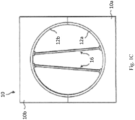
- the concave curvature of the upper shell 12b also has a tendency to force the shear webs 16 together slightly, as shown in FIG. 1C .
- Such movement of the shear webs 16 during mold closing may result in the shear webs 16 being bonded to the upper shell 12b at a sub-optimal position.
- WO2018/149526 A1 describes a method for producing a wind turbine blade including a connection between the shear web and the blade shell.
- US 2012/027612 A1 describes an alternative wind turbine blade shear web connection assembly.
- US 2004/011927 A1 describes a method for joining composite structural members.
- US 2015/0336368 A1 describes a method for applying adhesive in rotorcraft connection joints.
- the disclosed subject matter includes a spar cap according to claim 1.
- the present disclosure includes a method of forming a wind turbine blade component according to claim 9.
- the method includes engaging the shear web with the locating feature by positioning the shear web between first and second locating features of the spar cap and engaging the shear web with the bond gap feature by positioning the shear web on top of the bond gap feature of the spar cap. Additionally, an adhesive can be applied proximate the bond gap feature of the spar cap, wherein the adhesive is guided towards the locating feature.
- Figs. 2-12 an exemplary embodiment of the system in accordance with the disclosed subject matter is shown in Figs. 2-12 and is designated generally by reference character 1000. Similar reference numerals (differentiated by the leading numeral) may be provided among the various views and Figures presented herein to denote functionally corresponding, but not necessarily identical structures.
- a blade may include one or more longitudinally extending structural components configured to provide increased stiffness, buckling resistance and/or strength to the blade.
- the blade may include a pair of longitudinally extending spar caps 100 configured to be engaged against the opposing inner surfaces of the pressure and suction sides of the blade, respectively.
- one or more shear webs 120 may be disposed between the spar caps so as to form a beam-like configuration.
- the spar caps may generally be designed to control the bending stresses and/or other loads acting on the blade in a generally spanwise direction (a direction parallel to the span of the blade) during operation of a wind turbine.
- the spar caps may also be designed to withstand the spanwise compression occurring during operation of the wind turbine.
- the spar caps of the present disclosure can be constructed of a plurality of pultruded members grouped together to form a first portion of the spar caps.
- the pultruded members may be formed by impregnating a plurality of fibers (e.g. glass or carbon fibers) with a resin and curing the impregnated fibers.
- the fibers may be impregnated with the resin using any suitable means known in the art.
- the resin may include any suitable resin material, including but not limited to polyester, polyurethane, polybutylene terephthalate (PBT), polyethylene terephthalate (PET), vinyl ester, epoxy, or similar.
- the pultruded members separate into one or more pultruded member bundles as the spar cap approaches the blade root so as to form a second portion of the spar cap.
- the spar cap 100 is constructed of a plurality of pultruded members grouped together to form one or more layers.
- the layers may be stacked atop one another and joined together using any suitable means, for example, by vacuum infusing the members together or by bonding the members together via an adhesive, a semi-preg material, a pre-preg material, or similar.
- the methods and systems described herein facilitate obtaining uniform thickness of a profile segment of a spar cap and limiting/preventing undulations along a length of the reinforcing fibers of the profile segment, thereby increasing the alignment of the reinforcing fibers in the spar cap.
- the methods and systems described herein further facilitate increasing a load bearing characteristic of individual reinforcing fibers in a spar cap such that, to achieve a given load bearing characteristic for the entire spar cap, less reinforcing fibers are used and the mass of the spar cap is reduced.
- the methods and systems described herein facilitate using less expensive reinforcing fibers, such as carbon fibers, when fabricating a spar cap, thereby reducing a material cost and a labor cost associated with fabricating a spar cap.
- the methods and systems described herein facilitate reducing a cost associated with fabricating a wind turbine, while increasing the useful life of the wind turbine.
- pultrusion generally encompass reinforced materials (e.g. fibers or woven or braided strands) that are impregnated with a resin and pulled through a stationary die such that the resin cures or undergoes polymerization.
- the process of manufacturing pultruded members is typically characterized by a continuous process of composite materials that produces composite parts having a constant cross-section.
- the pultruded members as described herein may be used to construct various other rotor blade components, in addition to the spar cap.
- the pultruded members may be used to construct the shear web, or any other rotor blade component that can benefit from being constructed of a pultruded parts as described herein.
- a spar cap 100 is pultruded with a profile that includes locating feature 102 and a bond gap feature 103 on a "top" surface (i.e. the surface that will engage the shear web member, as discussed in further detail below).
- the locating feature(s) 102a,b secure proper cross-wise location of the shear web structure to the spar cap during assembly, and mold closure.
- the bond gap feature 103 establishes a minimum bod gap space or thickness for the adhesive that joins the shear web structure of the wind blade to the spar cap during assembly.
- the locating feature(s) 102a,b are configured as a protrusion that extends, upwardly from the top surface 101 of the spar cap, a greater distance than the bond gap feature 103.
- the locating feature(s) can be shaped as generally rectangular structures having planar inner surfaces configured to matingly engage the shear web 120 upon insertion of the web within the spar cap 100.
- the locating feature(s) 102 can extend up the shear web 120 a distance equal to or greater than the thickness/height of the flange, if present as some shear webs can be formed without a flange, on the shear web (as shown in Fig. 3 ).
- the inner surface of the locating features 102 can include depth markings to indicate the distance the shear web is inserted within the locating feature, thereby allowing an operator to visually confirm the desired depth (and thus stabilization and reinforcement) is achieved prior to, and/or after, applying adhesive.
- the outer edges of the locating features 102a,b can be chamfered or rounded so as to provide smoothed arcuate surfaces to reduce risk of injury to personnel and/or damage to other components during manufacture and assembly of the blade.
- the locating features 102 can be symmetrically disposed about a central axis of the spar cap 100.
- the locating feature(s) 102 can be integrally formed with the spar cap 100 and extending along the or length of the spar cap. Due to this integral structure formed via pultrusion, no additional components are needed for guiding/locating the shear web 120 during coupling to the spar cap, which is advantageous in that it avoids excess complexity, weight and costs.
- a bond gap feature 103 is provided for establishing and maintaining a space or gap between the shear web 120 and the upper surface of the spar cap 101.
- the bond gap feature 103 is a protrusion disposed between, and equidistant from, the locating features 102a,b.
- the bond gap feature 103 can be a single protrusion with an apex or pointed top, as shown.
- a the bond gap feature 103 can be a series of protrusions or "bumps" which form a path for channeling the adhesive towards the locating features 102a,b and/or along the span of the spar cap, as described in more detail below.
- the bond gap feature 103 extends away from the surface of the spar cap 101 a distance which is less than the distance in which locating features 102a,b extend.
- the bond gap feature 103 and locating feature 102a,b can be sized to extend the same distance, e.g. the entire length, along the spar cap and/or blade span. However, if desired, the bond gap feature 103 can extend different distances along the spar cap and/or blade span.
- the bond gap feature 103 can be formed with varying sizes and shapes.
- the bond gap feature 103 has a uniform size and shape along the spar cap span, and is integrally formed with the spar cap.
- the bond gap feature 103 cannot be dislodged or displaced with respect to the spar cap. Accordingly, assembly of the shear web is simplified, as well as performed more precisely, since these features can serve as reference points/frames for the global geometry of various other components forming the blade.
- an adhesive is applied within the region defined between the locating features 102a,b to facilitate assembly of the shear web to the spar cap.
- the integrity of this union is critical to fatigue life and blade performance as the forces exerted on the blade during operation are transmitted through this shear web and spar cap union. Accordingly, ensuring sufficient space is maintained between the bottom of the shear web 120 and the spar cap 101 is essential for providing a "pocket" or gap for the adhesive to reside and permanently couple the shear web 120 and spar cap 100.
- the shear web 120 is positioned within the blade mold, e.g. lowered into contact with the bond gap feature(s) 103, and positioned between the locating features 102a,b.
- the adhesive is (at least partially) applied prior to moving the shear web 120 into engagement with the spar cap bond gap 103 and locating features 102a,b.
- the adhesive can be applied after engagement of the shear web and spar cap. In such subsequent adhesive application, the adhesive can be dispensed from one end of the spar cap, with the bond gap feature 103 having a channel or series of protrusions for guiding the adhesive along the span of the spar cap.
- the gap formed by the bond gap feature 103 allows for easy visual confirmation that sufficient adhesive has been applied to fill the entire void or cavity formed between the shear web 120 and the spar cap 101.
- the bond gap feature 103 can be formed with a shape, e.g. triangular as shown in Figure 3 , which also guides or diverts the adhesive towards the locating features 102a,b. Accordingly, the bond gap feature 103 provides a non-stress riser shape of the adhesive line at the edge of the shear web 103 and the spar cap 100 location.
- shear web 120 is depicted in the exemplary embodiments, additional shear webs can be employed within the scope of the present disclosure.
- shear web 120 is depicted as an I-beam construction in Fig. 3
- alternative shear web configurations can be employed, e.g. split beams having generally a U-shape or V-shape construction, if so desired.
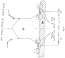
- Figure 4 depicts a box style, or double, shear web configuration, in accordance with the disclosed subject matter.
- the spar cap 100 is formed with a first set of locating features 102a,b, for engagement with the first web/flange of the shear web, and a second set of locating features 104a,b, for engagement with the second web/flange of the shear web.
- a first bond gap feature 103 is provided for engagement with the first web/flange of the shear web
- a second bond gap feature 105 is provided for engagement with the second web/flange of the shear web.
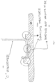
- FIG. 5 Another exemplary embodiment is depicted in Figure 5 , which show a C-shaped shear web has a first "leg” which engages a vertical surface of the locating feature 102b and a second "leg” which engages a vertical surface of the locating feature 102a, with the bottom of the shear web engaging the bond gap feature 103.
- This construction allows for secure and accurate placement of the shear web relative to the spar cap, without need for any additional points of reference for measurement, nor any additional components (e.g. clamps, brackets, screws, etc.) for securing the shear web to the spar cap.
- a guide is provided for applying and directing the adhesive, e.g. paste, to facilitate assembly of the spar cap 100 and shear web 120.
- the guide is configured as a paste shoe 200.
- the paste shoe guide 200 can include a registration feature for engaging the spar cap locating feature 102.
- the paste shoe guide 200 can include a laterally extending flange 202 which matingly receives the location feature 102 of the spar cap to secure the two components and prevent relative movement therebetween. This engagement, and restriction of relative movement, provides a uniform and defined cavity or "pocket" for receiving a predetermined amount of adhesive, as further described herein.
- the paste shoe guide 200 includes protruding feet 204 for contacting the spar cap 100.
- the paste shoe 200 can include conduits and ports for dispensing of adhesive within the paste shoe confines. After sufficient adhesive has been applied within the confines of the paste shoe 200, the paste shoe can be removed and the shear web can be installed in place. In some embodiments the paste shoe 200 extends along the entire span of the spar cap; in other embodiments the paste shoe can be a number of shoes which are distributed at select location(s) along the blade span.
- the paste shoe guide provides is the reduction in variation of adhesive application. Instead of manually marking a line to identify the paste application locations, the paste shoe guide ensures the proper amount of adhesive is applied, as well as shapes or directs the adhesive to occupy appropriate locations (e.g. shear web heel) thereby forming a secure union between components.
- a skin locator feature can be incorporated into the spar cap formation process.
- the spar cap can be formed, e.g. pultruded, with a feature that allows for engagement with the blade skin.
- the spar cap can be formed with a feature 110 for matingly receiving a complimentary feature in the blade skin.
- the skin locator feature 110 is shown as a recess, configured to receive a complimentary protrusion 310 formed on the blade skin, though the male/female arrangement of these features can be reversed, if so desired.
- the skin locator feature 110 can be formed at a single location (e.g. center, as shown in Figure 7 ) of the spar cap, or at multiple locations on the spar cap surface 101.
- the skin locator feature is advantageous in that it allows for rapid and accurate location/registration of the spar cap relative to the blade skin during layup of the blade skin segments. This avoids the need to employ fixtures of the external mold as the point of reference (which can be inaccurate and vary with different manufacturing cycles, and blade geometries). Additionally, the skin locator feature allows for rapid identification of locating parts directly featured on the spar cap and skin, while reducing error and providing instant visual confirmation of proper engagement.
- the spar caps can be formed as discrete elements which are coupled to the blade skin. In other embodiments, the spar caps are formed as components which are woven or blended into the blade skin so as to form an integral coupling.
- a caul plate 200 can be employed which includes a locator feature 202.
- the caul plate locator feature 202 engages the spar cap locating feature 102.
- the caul plate locator feature 202 can include a releasable coupling, e.g. screw or pin, for retaining the caul plate and spar cap in engagement during subsequent assembly processes.
- the caul plate locator feature 202 can engage the spar cap locating feature 102, such that the caul plate is restricted from movement/dislodgement, thereby permitting the caul plate 200 to remain present and securely engaged during the infusion process.
- adhesive can be guided or directed to completely fill the void proximate the heel of the shear web.
- the spar cap locating feature 102 forms a vertical wall which serves as a damn during application of adhesive within the bond gap between the spar cap 100 and shear web 120. This dam forces the adhesive to travel up along the vertical wall of spar cap locating feature 102, to completely fill the void or pocket, including the region proximate the transition radius of the shear web heel.
- the adhesive can be applied until it extends above the spar cap locating feature 102, thereby providing an immediate visual confirmation that the appropriate amount of adhesive has been applied.
- reference to "above”, “below”, “top”, “bottom”, etc. herein is relative and non-limiting as the structures and techniques described herein are equally applicable to spar caps formed on the suction side and pressure side of a blade.
Landscapes
- Engineering & Computer Science (AREA)
- Mechanical Engineering (AREA)
- Life Sciences & Earth Sciences (AREA)
- Sustainable Development (AREA)
- Sustainable Energy (AREA)
- Chemical & Material Sciences (AREA)
- Combustion & Propulsion (AREA)
- General Engineering & Computer Science (AREA)
- Physics & Mathematics (AREA)
- Fluid Mechanics (AREA)
- Wind Motors (AREA)
- Moulding By Coating Moulds (AREA)
Description
- The disclosed subject matter relates to a system, and corresponding method, of manufacturing large scale composite structures, e.g. wind turbine blades. These large scale composite structures are typically formed from a two-piece mold which, once the blade halves are molded, require a complex mold closure process to complete fabrication.
- Particularly, the present disclosure provides structural elements, e.g. spar caps, with a profile having various features which facilitate both placement and assembly of other components, e.g. shear web.
- Wind turbine blades generally comprise a hollow blade shell made primarily of composite materials, such as glass-fiber reinforced plastic. The blade shell is typically made up of two half shells, a lower pressure-side shell and an upper suction-side shell, which are molded separately in respective female half molds, before being bonded together along flanges at the leading and trailing edges of the blade. This method of manufacturing a blade is illustrated schematically in
FIG. 1a . - Referring to
FIG. 1 a, this shows amold 10 for a wind turbine blade divided into two half molds, an upper suction-side mold 10 a and a lower pressure-side mold 10 b, which are arranged side by side in an open configuration of the mold. A pressureside blade shell 12 a is supported on amold surface 14 a of thelower mold 10 a and a suctionside blade shell 12 b is supported on amold surface 14 b of theupper mold 10 b. Theshells - After forming the
shells respective mold halves shear webs 16 are bonded to aninner surface 17 of thewindward blade shell 12 a. Theshear webs 16 are longitudinally-extending structures that bridge the twohalf shells FIG. 1a, theshear webs 16 each comprise aweb 18 having alower edge 19 comprising a first longitudinally-extendingmounting flange 20 and anupper edge 21 comprising a second longitudinally-extendingmounting flange 22. Adhesive such as epoxy is applied along thesemounting flanges 22 in order to bond theshear webs 16 to therespective half shells - As shown in
FIG. 1b , once theshear webs 16 have been bonded to theupper blade shell 12a, adhesive is applied along the second (upper)mounting flanges 22 of theshear webs 16, and along the leadingedge 24 andtrailing edge 26 of theblade shells upper mold 10b, including theupper blade shell 12b, is then lifted, turned and placed on top of thelower blade mold 10a in order to bond the twoblade half shells trailing edges shear webs 16 to aninner surface 28 of theupper blade shell 12b. The step of placing one mold half on top of the other is referred to as closing the mold. - Referring now to
FIG. 1C , a problem can arise when themold 10 is closed whereby theshear webs 16 may move slightly relative to theupper shell 12b. For example, theshear webs 16 may move slightly under their own weight during mold closing or they may be dislodged by contact with theupper shell 12b. The concave curvature of theupper shell 12b also has a tendency to force theshear webs 16 together slightly, as shown inFIG. 1C . Such movement of theshear webs 16 during mold closing may result in theshear webs 16 being bonded to theupper shell 12b at a sub-optimal position. - Furthermore, there are various techniques which require employing permanent fixtures to guide the shear webs during mold closure. An example of which is provided in
U.S. Patent Publication No. 2017/0151711 . However, use of such permanent fixtures adversely impact the blade weight, as well as increasing design complexity and costs. -
WO2018/149526 A1 describes a method for producing a wind turbine blade including a connection between the shear web and the blade shell.US 2012/027612 A1 describes an alternative wind turbine blade shear web connection assembly.US 2004/011927 A1 describes a method for joining composite structural members.US 2015/0336368 A1 describes a method for applying adhesive in rotorcraft connection joints. - However, there remains a need for an efficient and economic method and system for providing guidance and bonding of the shear webs during the assembly phase of wind turbine devices that ensure proper placement of the shear web, without impacting the structure of the product.
- The purpose and advantages of the disclosed subject matter will be set forth in and apparent from the description that follows, as well as will be learned by practice of the disclosed subject matter. Additional advantages of the disclosed subject matter will be realized and attained by the methods and systems particularly pointed out in the written description and claims hereof, as well as from the appended drawings.
- To achieve these and other advantages and in accordance with the purpose of the disclosed subject matter, as embodied and broadly described, the disclosed subject matter includes a spar cap according to claim 1.
- Additionally, the present disclosure includes a method of forming a wind turbine blade component according to claim 9.
- In some embodiments the method includes engaging the shear web with the locating feature by positioning the shear web between first and second locating features of the spar cap and engaging the shear web with the bond gap feature by positioning the shear web on top of the bond gap feature of the spar cap. Additionally, an adhesive can be applied proximate the bond gap feature of the spar cap, wherein the adhesive is guided towards the locating feature.
- It is to be understood that both the foregoing general description and the following detailed description are exemplary and are intended to provide further explanation of the disclosed subject matter claimed.
- The accompanying drawings, which are incorporated in and constitute part of this specification, are included to illustrate and provide a further understanding of the method and system of the disclosed subject matter. Together with the description, the drawings serve to explain the principles of the disclosed subject matter.
- A detailed description of various aspects, features, and embodiments of the subject matter described herein is provided with reference to the accompanying drawings, which are briefly described below. The drawings are illustrative and are not necessarily drawn to scale, with some components and features being exaggerated for clarity. The drawings illustrate various aspects and features of the present subject matter and may illustrate one or more embodiment(s) or example(s) of the present subject matter in whole or in part.
-
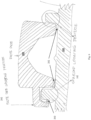
Figs. 1A-C depict cross-sectional views of a conventional wind turbine blade mold and manufacturing method. -
Figs. 2 and11-12 are cross-sectional views of spar cap profile in accordance with an embodiment of the present disclosure. -
Figs. 3-5 are a cross-sectional views of a various shear web geometries, positioned within the spar cap profile in accordance with an embodiment of the present disclosure. -
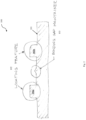
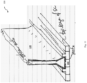
Fig. 6 is a cross-section of a adhesive guide shoe engaged with the spar cap profile in accordance with an embodiment of the present disclosure. -
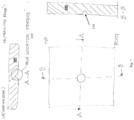
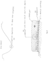
Figs. 7-10 are a cross-sectional views of a various spar cap geometries in accordance with the present disclosure. - Reference will now be made in detail to exemplary embodiments of the disclosed subject matter, an example of which is illustrated in the accompanying drawings. The method and corresponding steps of the disclosed subject matter will be described in conjunction with the detailed description of the system.
- The methods and systems presented herein may be used for large structure construction. The disclosed subject matter is particularly suited for construction of wind turbine blades. For purpose of explanation and illustration, and not limitation, an exemplary embodiment of the system in accordance with the disclosed subject matter is shown in
Figs. 2-12 and is designated generally by reference character 1000. Similar reference numerals (differentiated by the leading numeral) may be provided among the various views and Figures presented herein to denote functionally corresponding, but not necessarily identical structures. - A blade may include one or more longitudinally extending structural components configured to provide increased stiffness, buckling resistance and/or strength to the blade. For example, the blade may include a pair of longitudinally extending spar caps 100 configured to be engaged against the opposing inner surfaces of the pressure and suction sides of the blade, respectively. Additionally, one or more
shear webs 120 may be disposed between the spar caps so as to form a beam-like configuration. The spar caps may generally be designed to control the bending stresses and/or other loads acting on the blade in a generally spanwise direction (a direction parallel to the span of the blade) during operation of a wind turbine. Similarly, the spar caps may also be designed to withstand the spanwise compression occurring during operation of the wind turbine. - The spar caps of the present disclosure can be constructed of a plurality of pultruded members grouped together to form a first portion of the spar caps. In certain embodiments, the pultruded members may be formed by impregnating a plurality of fibers (e.g. glass or carbon fibers) with a resin and curing the impregnated fibers. The fibers may be impregnated with the resin using any suitable means known in the art. Further, the resin may include any suitable resin material, including but not limited to polyester, polyurethane, polybutylene terephthalate (PBT), polyethylene terephthalate (PET), vinyl ester, epoxy, or similar. Further, as shown, the pultruded members separate into one or more pultruded member bundles as the spar cap approaches the blade root so as to form a second portion of the spar cap.
- More specifically, the
spar cap 100 is constructed of a plurality of pultruded members grouped together to form one or more layers. Thus, the layers may be stacked atop one another and joined together using any suitable means, for example, by vacuum infusing the members together or by bonding the members together via an adhesive, a semi-preg material, a pre-preg material, or similar. - The methods and systems described herein facilitate obtaining uniform thickness of a profile segment of a spar cap and limiting/preventing undulations along a length of the reinforcing fibers of the profile segment, thereby increasing the alignment of the reinforcing fibers in the spar cap. The methods and systems described herein further facilitate increasing a load bearing characteristic of individual reinforcing fibers in a spar cap such that, to achieve a given load bearing characteristic for the entire spar cap, less reinforcing fibers are used and the mass of the spar cap is reduced. Additionally, the methods and systems described herein facilitate using less expensive reinforcing fibers, such as carbon fibers, when fabricating a spar cap, thereby reducing a material cost and a labor cost associated with fabricating a spar cap. As such, the methods and systems described herein facilitate reducing a cost associated with fabricating a wind turbine, while increasing the useful life of the wind turbine.
- As shown in
Fig. 2 , a series of locating elements/features are crated into pultrusion profiles of the spar caps of wind turbine blades. The reference to "pultrusion" or similar generally encompass reinforced materials (e.g. fibers or woven or braided strands) that are impregnated with a resin and pulled through a stationary die such that the resin cures or undergoes polymerization. As such, the process of manufacturing pultruded members is typically characterized by a continuous process of composite materials that produces composite parts having a constant cross-section. It should also be understood that the pultruded members as described herein may be used to construct various other rotor blade components, in addition to the spar cap. For example, in certain embodiments, the pultruded members may be used to construct the shear web, or any other rotor blade component that can benefit from being constructed of a pultruded parts as described herein. - In the exemplary embodiment shown, a
spar cap 100 is pultruded with a profile that includes locatingfeature 102 and a bond gap feature 103 on a "top" surface (i.e. the surface that will engage the shear web member, as discussed in further detail below). The locating feature(s) 102a,b secure proper cross-wise location of the shear web structure to the spar cap during assembly, and mold closure. Thebond gap feature 103 establishes a minimum bod gap space or thickness for the adhesive that joins the shear web structure of the wind blade to the spar cap during assembly. - In some embodiments, the locating feature(s) 102a,b are configured as a protrusion that extends, upwardly from the
top surface 101 of the spar cap, a greater distance than thebond gap feature 103. The locating feature(s) can be shaped as generally rectangular structures having planar inner surfaces configured to matingly engage theshear web 120 upon insertion of the web within thespar cap 100. The locating feature(s) 102 can extend up the shear web 120 a distance equal to or greater than the thickness/height of the flange, if present as some shear webs can be formed without a flange, on the shear web (as shown inFig. 3 ). The greater the distance locating features 102 extend, the greater the degree of engagement and support with theshear web 120. In some embodiments, the inner surface of the locating features 102 can include depth markings to indicate the distance the shear web is inserted within the locating feature, thereby allowing an operator to visually confirm the desired depth (and thus stabilization and reinforcement) is achieved prior to, and/or after, applying adhesive. Also, the outer edges of the locating features 102a,b can be chamfered or rounded so as to provide smoothed arcuate surfaces to reduce risk of injury to personnel and/or damage to other components during manufacture and assembly of the blade. Additionally, the locating features 102 can be symmetrically disposed about a central axis of thespar cap 100. - The locating feature(s) 102 can be integrally formed with the
spar cap 100 and extending along the or length of the spar cap. Due to this integral structure formed via pultrusion, no additional components are needed for guiding/locating theshear web 120 during coupling to the spar cap, which is advantageous in that it avoids excess complexity, weight and costs. - In accordance with another aspect of the disclosure, a
bond gap feature 103 is provided for establishing and maintaining a space or gap between theshear web 120 and the upper surface of thespar cap 101. In the exemplary embodiment shown, thebond gap feature 103 is a protrusion disposed between, and equidistant from, the locating features 102a,b. The bond gap feature 103 can be a single protrusion with an apex or pointed top, as shown. Additionally or alternatively, in some embodiments a the bond gap feature 103 can be a series of protrusions or "bumps" which form a path for channeling the adhesive towards the locatingfeatures 102a,b and/or along the span of the spar cap, as described in more detail below. Typically, thebond gap feature 103 extends away from the surface of the spar cap 101 a distance which is less than the distance in which locating features 102a,b extend. Thebond gap feature 103 and locatingfeature 102a,b can be sized to extend the same distance, e.g. the entire length, along the spar cap and/or blade span. However, if desired, the bond gap feature 103 can extend different distances along the spar cap and/or blade span. - The bond gap feature 103 can be formed with varying sizes and shapes. In some embodiments, the
bond gap feature 103 has a uniform size and shape along the spar cap span, and is integrally formed with the spar cap. Thus, similarly to the locating features 102a,b, the bond gap feature 103 cannot be dislodged or displaced with respect to the spar cap. Accordingly, assembly of the shear web is simplified, as well as performed more precisely, since these features can serve as reference points/frames for the global geometry of various other components forming the blade. - In operation, an adhesive is applied within the region defined between the locating
features 102a,b to facilitate assembly of the shear web to the spar cap. As noted above, the integrity of this union is critical to fatigue life and blade performance as the forces exerted on the blade during operation are transmitted through this shear web and spar cap union. Accordingly, ensuring sufficient space is maintained between the bottom of theshear web 120 and thespar cap 101 is essential for providing a "pocket" or gap for the adhesive to reside and permanently couple theshear web 120 andspar cap 100. - The
shear web 120 is positioned within the blade mold, e.g. lowered into contact with the bond gap feature(s) 103, and positioned between the locatingfeatures 102a,b. In some embodiments, the adhesive is (at least partially) applied prior to moving theshear web 120 into engagement with the sparcap bond gap 103 and locatingfeatures 102a,b. Additionally or alternatively, the adhesive can be applied after engagement of the shear web and spar cap. In such subsequent adhesive application, the adhesive can be dispensed from one end of the spar cap, with the bond gap feature 103 having a channel or series of protrusions for guiding the adhesive along the span of the spar cap. Also, the gap formed by thebond gap feature 103 allows for easy visual confirmation that sufficient adhesive has been applied to fill the entire void or cavity formed between theshear web 120 and thespar cap 101. Similarly, the bond gap feature 103 can be formed with a shape, e.g. triangular as shown inFigure 3 , which also guides or diverts the adhesive towards the locatingfeatures 102a,b. Accordingly, thebond gap feature 103 provides a non-stress riser shape of the adhesive line at the edge of theshear web 103 and thespar cap 100 location. - Although only a
single shear web 120 is depicted in the exemplary embodiments, additional shear webs can be employed within the scope of the present disclosure. Furthermore, although theshear web 120 is depicted as an I-beam construction inFig. 3 , alternative shear web configurations can be employed, e.g. split beams having generally a U-shape or V-shape construction, if so desired. - For example,
Figure 4 depicts a box style, or double, shear web configuration, in accordance with the disclosed subject matter. In such embodiments thespar cap 100 is formed with a first set of locatingfeatures 102a,b, for engagement with the first web/flange of the shear web, and a second set of locatingfeatures 104a,b, for engagement with the second web/flange of the shear web. Additionally, a firstbond gap feature 103 is provided for engagement with the first web/flange of the shear web, and a secondbond gap feature 105 is provided for engagement with the second web/flange of the shear web. - Another exemplary embodiment is depicted in
Figure 5 , which show a C-shaped shear web has a first "leg" which engages a vertical surface of the locatingfeature 102b and a second "leg" which engages a vertical surface of the locatingfeature 102a, with the bottom of the shear web engaging thebond gap feature 103. This construction allows for secure and accurate placement of the shear web relative to the spar cap, without need for any additional points of reference for measurement, nor any additional components (e.g. clamps, brackets, screws, etc.) for securing the shear web to the spar cap. - In accordance with another aspect of the disclosure, a guide is provided for applying and directing the adhesive, e.g. paste, to facilitate assembly of the
spar cap 100 andshear web 120. - In the exemplary embodiment shown in
Figure 6 , the guide is configured as apaste shoe 200. Thepaste shoe guide 200 can include a registration feature for engaging the sparcap locating feature 102. For example, thepaste shoe guide 200 can include a laterally extendingflange 202 which matingly receives thelocation feature 102 of the spar cap to secure the two components and prevent relative movement therebetween. This engagement, and restriction of relative movement, provides a uniform and defined cavity or "pocket" for receiving a predetermined amount of adhesive, as further described herein. Additionally, in some embodiments thepaste shoe guide 200 includes protruding feet 204 for contacting thespar cap 100. - In some embodiments the
paste shoe 200 can include conduits and ports for dispensing of adhesive within the paste shoe confines. After sufficient adhesive has been applied within the confines of thepaste shoe 200, the paste shoe can be removed and the shear web can be installed in place. In some embodiments thepaste shoe 200 extends along the entire span of the spar cap; in other embodiments the paste shoe can be a number of shoes which are distributed at select location(s) along the blade span. - Among the advantages the paste shoe guide provides is the reduction in variation of adhesive application. Instead of manually marking a line to identify the paste application locations, the paste shoe guide ensures the proper amount of adhesive is applied, as well as shapes or directs the adhesive to occupy appropriate locations (e.g. shear web heel) thereby forming a secure union between components.
- In accordance with another aspect of the disclosure, a skin locator feature can be incorporated into the spar cap formation process. In the exemplary embodiment shown in
Figures 7-8 , the spar cap can be formed, e.g. pultruded, with a feature that allows for engagement with the blade skin. For instance, the spar cap can be formed with afeature 110 for matingly receiving a complimentary feature in the blade skin. For purpose of illustration and not limitation, theskin locator feature 110 is shown as a recess, configured to receive acomplimentary protrusion 310 formed on the blade skin, though the male/female arrangement of these features can be reversed, if so desired. - The
skin locator feature 110 can be formed at a single location (e.g. center, as shown inFigure 7 ) of the spar cap, or at multiple locations on thespar cap surface 101. The skin locator feature is advantageous in that it allows for rapid and accurate location/registration of the spar cap relative to the blade skin during layup of the blade skin segments. This avoids the need to employ fixtures of the external mold as the point of reference (which can be inaccurate and vary with different manufacturing cycles, and blade geometries). Additionally, the skin locator feature allows for rapid identification of locating parts directly featured on the spar cap and skin, while reducing error and providing instant visual confirmation of proper engagement. - In some embodiments the spar caps can be formed as discrete elements which are coupled to the blade skin. In other embodiments, the spar caps are formed as components which are woven or blended into the blade skin so as to form an integral coupling.
- In accordance with another aspect of the disclosure, a
caul plate 200 can be employed which includes alocator feature 202. In the exemplary embodiment shown inFigure 9 , the caulplate locator feature 202 engages the sparcap locating feature 102. In some embodiment, the caulplate locator feature 202 can include a releasable coupling, e.g. screw or pin, for retaining the caul plate and spar cap in engagement during subsequent assembly processes. For example, the caulplate locator feature 202 can engage the sparcap locating feature 102, such that the caul plate is restricted from movement/dislodgement, thereby permitting thecaul plate 200 to remain present and securely engaged during the infusion process. - In accordance with another aspect of the disclosure, adhesive can be guided or directed to completely fill the void proximate the heel of the shear web. In the exemplary embodiment shown in
Figure 10 , the sparcap locating feature 102 forms a vertical wall which serves as a damn during application of adhesive within the bond gap between thespar cap 100 andshear web 120. This dam forces the adhesive to travel up along the vertical wall of sparcap locating feature 102, to completely fill the void or pocket, including the region proximate the transition radius of the shear web heel. The adhesive can be applied until it extends above the sparcap locating feature 102, thereby providing an immediate visual confirmation that the appropriate amount of adhesive has been applied. It should be noted, that reference to "above", "below", "top", "bottom", etc. herein is relative and non-limiting as the structures and techniques described herein are equally applicable to spar caps formed on the suction side and pressure side of a blade. - Accordingly, the present disclosure provides numerous advantages and improvements over conventional blade structures and manufacturing techniques, including:
- Eliminates the need for massive gantries to locate the shear web and hold it in position during location and bonding;
- Avoids manual shaping of the glue line to eliminate stress riser shape and "crash condition" bond line between the shear web and spar cap, and makes assessment of bond line adhesive amounts easier and less likely to be flawed;
- Provides complete filling of shear web heel without adding/bonding secondary parts to re-direct the adhesive squeeze out;
- Provides point of reference with respect to blade components, rather than external mold frame, thereby the reference features can remain inside the vacuum bagging;
- Provides spar cap locating fixture to be integral to spar cap, eliminates possibilities of sliding/movement during lay-up process.
- While the disclosed subject matter is described herein in terms of certain preferred embodiments, those skilled in the art will recognize that various modifications and improvements may be made to the disclosed subject matter without departing from the scope thereof. Moreover, although individual features of one embodiment of the disclosed subject matter may be discussed herein or shown in the drawings of the one embodiment and not in other embodiments, it should be apparent that individual features of one embodiment may be combined with one or more features of another embodiment or features from a plurality of embodiments.
- In addition to the specific embodiments claimed below, the disclosed subject matter is also directed to other embodiments having any other possible combination of the dependent features claimed below and those disclosed above. As such, the particular features presented in the dependent claims and disclosed above can be combined with each other in other manners within the scope of the disclosed subject matter such that the disclosed subject matter should be recognized as also specifically directed to other embodiments having any other possible combinations. Thus, the foregoing description of specific embodiments of the disclosed subject matter has been presented for purposes of illustration and description. It is not intended to be exhaustive or to limit the disclosed subject matter to those embodiments disclosed.
- It will be apparent to those skilled in the art that various modifications and variations can be made in the method and system of the disclosed subject matter without departing from the scope of the appended claims.
Claims (15)
- A spar cap (100) comprising:a first surface (101) and a second surface defining a thickness therebetween;at least one locating feature (102) disposed on the first surface (101), the at least one locating feature (102) extending vertically from the first surface (101) of the spar cap (100);at least one bond gap feature (103) formed as a protrusion and disposed on the first surface (101), the bond gap feature (103) maintaining a space between a shear web (120) and the first surface (101) of the spar cap;the locating feature(s) and bond gap feature(s) integrally formed with the first surface (101) of the spar cap (100) and fixed relative to the first surface (101) of the spar cap (100); andwherein the vertical wall of the at least one of the locating feature(s) and bond gap feature(s) is configured to engage the shear web.
- The spar cap (100) of claim 1, wherein the at least one locating feature (102) is a protrusion.
- The spar cap (100) of claim 1, wherein a bond gap feature protrudes a first distance from the first surface, and a locating feature protrudes a second distance from the first surface.
- The spar cap (100) of claim 1, further comprising a plurality of locating features (102) symmetrically disposed about a central axis of the spar cap (100).
- The spar cap (100) of claim 1, further comprising first and second locating features (102a, 102b) with a bond gap feature (103) disposed therebetween.
- The spar cap (100) of claim 1, wherein the bond gap feature (103) is configured to engage a bottom surface of the shear web (120).
- The spar cap (100) of claim 1, wherein the locating feature (102) is configured to engage a side surface of the shear web (120).
- The spar cap (100) of claim 1, wherein the bond gap feature (103) extends along the length of the blade span; and
the locating feature (102) extends along the length of the blade span. - A method of forming a wind turbine blade component comprising:forming a spar cap (100) with a first surface (101) and a second surface defining a thickness therebetween;forming at least one locating feature (102) on the first surface (101), the at least one locating feature (102) extending vertically from the first surface (101) of the spar cap (100);forming at least one bond gap feature (103) as a protrusion on the first surface (101), the at least one bond gap feature (102) extending vertically from the first surface (101) of the spar cap (100), the bond gap feature (103) configured to engage a shear web (120) and maintain a space between the shear web and the first surface (101) of the spar cap;the locating feature(s) and bond gap feature(s) integrally formed with the first surface (101) of the spar cap (100) and fixed relative to the first surface (101) of the spar cap (100);wherein at least one of the locating feature(s) and bond gap feature(s) is configured to engage the shear web (120); andcontacting the spar cap (100) with a paste shoe guide (200), the paste shoe guide (200) having a registration feature with a laterally extending flange (202) for engaging the at least one spar cap locating feature (102), and protruding feet for contacting the first surface (101) of the spar cap (100).
- The method of claim 9, wherein the forming includes pultrusion.
- The method of claim 9, wherein at least one of the locating feature (102) is a protrusion.
- The method of claim 9, further comprising removing the paste shoe guide (200) and engaging a shear web (120) with the locating feature (102) of the spar cap (100) by positioning the shear web (120) between first and second locating features (102a, 102b) of the spar cap (100).
- The method of claim 9, further comprising removing the paste shoe guide (200) and engaging a shear web (120) with the bond gap feature (103) of the spar cap (100) by positioning the shear web (120) on top of the bond gap feature (103) of the spar cap (100).
- The method of claim 9, further comprising applying an adhesive proximate the bond gap feature (103) of the spar cap (100), wherein adhesive is guided towards the locating feature (102).
- The method of claim 9, wherein the locating feature (102) and bond gap feature (103) are formed to extend along the length of the blade span.
Applications Claiming Priority (2)
| Application Number | Priority Date | Filing Date | Title |
|---|---|---|---|
| US201862729501P | 2018-09-11 | 2018-09-11 | |
| PCT/US2018/050673 WO2020055396A1 (en) | 2018-09-11 | 2018-09-12 | Positioning profiles for pultrusions in wind blade spar caps |
Publications (3)
| Publication Number | Publication Date |
|---|---|
| EP3849784A1 EP3849784A1 (en) | 2021-07-21 |
| EP3849784A4 EP3849784A4 (en) | 2022-06-08 |
| EP3849784B1 true EP3849784B1 (en) | 2025-04-30 |
Family
ID=69720634
Family Applications (1)
| Application Number | Title | Priority Date | Filing Date |
|---|---|---|---|
| EP18933064.0A Active EP3849784B1 (en) | 2018-09-11 | 2018-09-12 | Positioning profiles for pultrusions in wind blade spar caps |
Country Status (8)
| Country | Link |
|---|---|
| US (2) | US11041478B2 (en) |
| EP (1) | EP3849784B1 (en) |
| JP (1) | JP6993542B2 (en) |
| CN (1) | CN112912235B (en) |
| DK (1) | DK3849784T3 (en) |
| ES (1) | ES3033561T3 (en) |
| MX (1) | MX2021002823A (en) |
| WO (1) | WO2020055396A1 (en) |
Families Citing this family (11)
| Publication number | Priority date | Publication date | Assignee | Title |
|---|---|---|---|---|
| CN109641408A (en) * | 2016-06-28 | 2019-04-16 | 维斯塔斯风力系统有限公司 | Manufacturing method of wind turbine blade |
| US11761421B2 (en) * | 2017-11-10 | 2023-09-19 | Vestas Wind Systems A/S | Wind turbine blade manufacture |
| JP6993542B2 (en) | 2018-09-11 | 2022-02-04 | ティーピーアイ コンポジッツ,インコーポレーティッド | Alignment profile for pultrusion of wind blade spur caps |
| US11840038B2 (en) * | 2018-12-03 | 2023-12-12 | Vestas Wind Systems A/S | Wind turbine blade manufacture |
| CN111844791B (en) * | 2020-07-03 | 2025-07-11 | 白银中科宇能科技有限公司 | A wind turbine blade positioning and pressing device |
| CN111775456A (en) * | 2020-07-07 | 2020-10-16 | 株洲时代新材料科技股份有限公司 | Manufacturing method of concave main beam wind power blade and concave main beam wind power blade |
| EP4174310B1 (en) * | 2021-10-27 | 2026-03-25 | LM Wind Power A/S | Segmented wind turbine blade |
| CN114211797B (en) * | 2021-11-24 | 2024-01-23 | 东方电气风电股份有限公司 | Wind turbine blade web rapid bonding structure and rapid prototyping method |
| US12240195B2 (en) | 2021-12-01 | 2025-03-04 | Vestas Wind Systems A/S | Wind turbine blade shear webs |
| CN114379113B (en) * | 2021-12-31 | 2023-12-29 | 天津爱思达航天科技有限公司 | I-beam forming die and forming process |
| US20250091298A1 (en) * | 2023-09-20 | 2025-03-20 | B/E Aerospace, Inc. | Joints for composite laminated panels and beams |
Family Cites Families (28)
| Publication number | Priority date | Publication date | Assignee | Title |
|---|---|---|---|---|
| US6945727B2 (en) * | 2002-07-19 | 2005-09-20 | The Boeing Company | Apparatuses and methods for joining structural members, such as composite structural members |
| US7393488B2 (en) * | 2005-05-25 | 2008-07-01 | The Boeing Company | Methods of joining structures and joints formed thereby |
| EP1754589B1 (en) * | 2005-08-17 | 2015-10-14 | General Electric Company | Use of continuous laminates, in particular suitable as a spar cap or another part of a wind energy turbine rotor blade |
| US7670527B2 (en) * | 2006-05-09 | 2010-03-02 | Lockheed Martin Corporation | Failsafe injected adhesive joint |
| WO2008104174A2 (en) * | 2007-02-27 | 2008-09-04 | Vestas Wind Systems A/S | A strengthening structure for a wind turbine blade, a wind turbine blade, a method for assembling a wind turbine blade and use hereof. |
| EP2357357B1 (en) * | 2009-10-01 | 2016-11-09 | Vestas Wind Systems A/S | Wind turbine blade |
| US7922454B1 (en) * | 2010-10-29 | 2011-04-12 | General Electric Company | Joint design for rotor blade segments of a wind turbine |
| CN103261021B (en) * | 2010-12-28 | 2016-01-20 | 贝尔直升机泰克斯特龙公司 | Multidirectional Load Connection System |
| US8235671B2 (en) * | 2011-07-19 | 2012-08-07 | General Electric Company | Wind turbine blade shear web connection assembly |
| US8393871B2 (en) * | 2011-07-19 | 2013-03-12 | General Electric Company | Wind turbine blade shear web connection assembly |
| BR112014002704A2 (en) * | 2011-08-05 | 2015-04-22 | Tecsis Tecnologia E Sist S Avançados S A | Windmill blade tip segment and mounting method |
| US9932958B2 (en) * | 2012-12-20 | 2018-04-03 | Vestas Wind Systems A/S | Turbine blade shear web alignment |
| JP6169465B2 (en) * | 2013-10-02 | 2017-07-26 | 三菱重工業株式会社 | Joints and aircraft structures |
| US20150152838A1 (en) | 2013-12-02 | 2015-06-04 | General Electric Company | Spar caps-shear web assembly configuration for wind turbine blades, and methods thereof |
| EP3137281B1 (en) | 2014-05-01 | 2021-08-04 | LM WP Patent Holding A/S | A system and method of manufacturing a wind turbine blade |
| US9713917B2 (en) * | 2014-05-21 | 2017-07-25 | Bell Helicopter Textron Inc. | Adhesive application in rotorcraft connection joints |
| US20150369211A1 (en) * | 2014-06-19 | 2015-12-24 | General Electric Company | Wind blade tip joint |
| GB2527587A (en) | 2014-06-27 | 2015-12-30 | Vestas Wind Sys As | Improvements relating to wind turbine blade manufacture |
| GB2529439A (en) * | 2014-08-20 | 2016-02-24 | Vestas Wind Sys As | Improvements relating to wind turbine blade manufacture |
| GB2535697A (en) * | 2015-02-17 | 2016-08-31 | Vestas Wind Sys As | Improvements relating to wind turbine blade manufacture |
| WO2016189051A1 (en) * | 2015-05-28 | 2016-12-01 | Lm Wp Patent Holding A/S | Wind turbine blade with a trailing edge spacing section |
| DK3329118T3 (en) * | 2015-07-28 | 2019-10-07 | Vestas Wind Sys As | IMPROVEMENTS IN THE WINDOW EXPERIENCE |
| US10422315B2 (en) * | 2015-09-01 | 2019-09-24 | General Electric Company | Pultruded components for a shear web of a wind turbine rotor blade |
| CN109641408A (en) * | 2016-06-28 | 2019-04-16 | 维斯塔斯风力系统有限公司 | Manufacturing method of wind turbine blade |
| US10690111B2 (en) | 2016-12-02 | 2020-06-23 | General Electric Company | Wind turbine rotor blade |
| WO2018149526A1 (en) * | 2017-02-17 | 2018-08-23 | Siemens Wind Power A/S | A wind turbine blade, a wind turbine and a method for producing a wind turbine blade |
| DK3501810T3 (en) * | 2017-12-22 | 2022-07-04 | Siemens Gamesa Renewable Energy As | Pultruded fiber composite strips with corrugated profiles for spar caps for wind turbine blades |
| JP6993542B2 (en) | 2018-09-11 | 2022-02-04 | ティーピーアイ コンポジッツ,インコーポレーティッド | Alignment profile for pultrusion of wind blade spur caps |
-
2018
- 2018-09-12 JP JP2021537439A patent/JP6993542B2/en active Active
- 2018-09-12 EP EP18933064.0A patent/EP3849784B1/en active Active
- 2018-09-12 CN CN201880098799.9A patent/CN112912235B/en not_active Expired - Fee Related
- 2018-09-12 US US16/129,362 patent/US11041478B2/en active Active
- 2018-09-12 DK DK18933064.0T patent/DK3849784T3/en active
- 2018-09-12 WO PCT/US2018/050673 patent/WO2020055396A1/en not_active Ceased
- 2018-09-12 ES ES18933064T patent/ES3033561T3/en active Active
- 2018-09-12 MX MX2021002823A patent/MX2021002823A/en unknown
-
2021
- 2021-06-21 US US17/353,316 patent/US11598309B2/en active Active
Also Published As
| Publication number | Publication date |
|---|---|
| US20200080542A1 (en) | 2020-03-12 |
| DK3849784T3 (en) | 2025-05-19 |
| CN112912235A (en) | 2021-06-04 |
| CN112912235B (en) | 2022-05-27 |
| EP3849784A1 (en) | 2021-07-21 |
| JP2021532309A (en) | 2021-11-25 |
| ES3033561T3 (en) | 2025-08-05 |
| MX2021002823A (en) | 2021-08-11 |
| US11598309B2 (en) | 2023-03-07 |
| US20210340949A1 (en) | 2021-11-04 |
| EP3849784A4 (en) | 2022-06-08 |
| JP6993542B2 (en) | 2022-02-04 |
| US11041478B2 (en) | 2021-06-22 |
| WO2020055396A1 (en) | 2020-03-19 |
Similar Documents
| Publication | Publication Date | Title |
|---|---|---|
| US11598309B2 (en) | Positioning profiles for pultrusions in wind blade spar caps | |
| CN107107487B (en) | Fabrication of I-Shaped Shear Webs | |
| CN107708982B (en) | Reinforcing structures for wind turbine blades | |
| US9599094B2 (en) | Method of manufacturing an aerodynamic shell part for a wind turbine blade | |
| CN111246992B (en) | Wind turbine blade comprising a root structure with adaptive positioning of pultruded elements | |
| CN110167751A (en) | Reinforcement structure for wind turbine blade | |
| CN113665142A (en) | Shear web mold system including variable mold plates | |
| EP3548261B1 (en) | Method and system for manufacturing a shear web for a wind turbine blade | |
| US10953611B2 (en) | Blade mould for manufacturing a blade shell part of a wind turbine blade and related method | |
| EP3623614A1 (en) | A shear web with a core for a wind turbine blade | |
| EP3183454B1 (en) | A reinforced wind turbine blade component | |
| EP3573803B1 (en) | Method and apparatus for assembling a reinforcement web for use in a wind turbine blade | |
| EP3027892A1 (en) | A blade for a wind turbine and a method for manufacturing a blade for a wind turbine | |
| US9932109B2 (en) | Method of fabricating a spar for a blade, a method of fabricating a blade, and a blade | |
| US20250100237A1 (en) | Mold assembly for infusing a spar cap and related methods | |
| US11884027B2 (en) | Wind turbine blade mold with built-in high precision geometric references on B-surface |
Legal Events
| Date | Code | Title | Description |
|---|---|---|---|
| STAA | Information on the status of an ep patent application or granted ep patent |
Free format text: STATUS: THE INTERNATIONAL PUBLICATION HAS BEEN MADE |
|
| PUAI | Public reference made under article 153(3) epc to a published international application that has entered the european phase |
Free format text: ORIGINAL CODE: 0009012 |
|
| STAA | Information on the status of an ep patent application or granted ep patent |
Free format text: STATUS: REQUEST FOR EXAMINATION WAS MADE |
|
| 17P | Request for examination filed |
Effective date: 20210329 |
|
| AK | Designated contracting states |
Kind code of ref document: A1 Designated state(s): AL AT BE BG CH CY CZ DE DK EE ES FI FR GB GR HR HU IE IS IT LI LT LU LV MC MK MT NL NO PL PT RO RS SE SI SK SM TR |
|
| DAV | Request for validation of the european patent (deleted) | ||
| DAX | Request for extension of the european patent (deleted) | ||
| A4 | Supplementary search report drawn up and despatched |
Effective date: 20220506 |
|
| RIC1 | Information provided on ipc code assigned before grant |
Ipc: B29C 65/78 20060101ALN20220429BHEP Ipc: B29C 65/52 20060101ALN20220429BHEP Ipc: B63H 1/26 20060101ALI20220429BHEP Ipc: B29C 65/48 20060101AFI20220429BHEP |
|
| GRAP | Despatch of communication of intention to grant a patent |
Free format text: ORIGINAL CODE: EPIDOSNIGR1 |
|
| STAA | Information on the status of an ep patent application or granted ep patent |
Free format text: STATUS: GRANT OF PATENT IS INTENDED |
|
| RIC1 | Information provided on ipc code assigned before grant |
Ipc: B29C 65/78 20060101ALN20241108BHEP Ipc: B29C 65/52 20060101ALN20241108BHEP Ipc: B63H 1/26 20060101ALI20241108BHEP Ipc: B29C 65/48 20060101AFI20241108BHEP |
|
| INTG | Intention to grant announced |
Effective date: 20241129 |
|
| GRAS | Grant fee paid |
Free format text: ORIGINAL CODE: EPIDOSNIGR3 |
|
| GRAA | (expected) grant |
Free format text: ORIGINAL CODE: 0009210 |
|
| STAA | Information on the status of an ep patent application or granted ep patent |
Free format text: STATUS: THE PATENT HAS BEEN GRANTED |
|
| AK | Designated contracting states |
Kind code of ref document: B1 Designated state(s): AL AT BE BG CH CY CZ DE DK EE ES FI FR GB GR HR HU IE IS IT LI LT LU LV MC MK MT NL NO PL PT RO RS SE SI SK SM TR |
|
| REG | Reference to a national code |
Ref country code: CH Ref legal event code: EP Ref country code: GB Ref legal event code: FG4D |
|
| REG | Reference to a national code |
Ref country code: DE Ref legal event code: R096 Ref document number: 602018081636 Country of ref document: DE |
|
| REG | Reference to a national code |
Ref country code: DK Ref legal event code: T3 Effective date: 20250515 |
|
| REG | Reference to a national code |
Ref country code: IE Ref legal event code: FG4D |
|
| REG | Reference to a national code |
Ref country code: ES Ref legal event code: FG2A Ref document number: 3033561 Country of ref document: ES Kind code of ref document: T3 Effective date: 20250805 |
|
| REG | Reference to a national code |
Ref country code: NL Ref legal event code: MP Effective date: 20250430 |
|
| REG | Reference to a national code |
Ref country code: AT Ref legal event code: MK05 Ref document number: 1789656 Country of ref document: AT Kind code of ref document: T Effective date: 20250430 |
|
| PG25 | Lapsed in a contracting state [announced via postgrant information from national office to epo] |
Ref country code: FI Free format text: LAPSE BECAUSE OF FAILURE TO SUBMIT A TRANSLATION OF THE DESCRIPTION OR TO PAY THE FEE WITHIN THE PRESCRIBED TIME-LIMIT Effective date: 20250430 Ref country code: PT Free format text: LAPSE BECAUSE OF FAILURE TO SUBMIT A TRANSLATION OF THE DESCRIPTION OR TO PAY THE FEE WITHIN THE PRESCRIBED TIME-LIMIT Effective date: 20250901 |
|
| PGFP | Annual fee paid to national office [announced via postgrant information from national office to epo] |
Ref country code: DK Payment date: 20250925 Year of fee payment: 8 Ref country code: DE Payment date: 20250929 Year of fee payment: 8 |
|
| REG | Reference to a national code |
Ref country code: LT Ref legal event code: MG9D |
|
| PG25 | Lapsed in a contracting state [announced via postgrant information from national office to epo] |
Ref country code: NO Free format text: LAPSE BECAUSE OF FAILURE TO SUBMIT A TRANSLATION OF THE DESCRIPTION OR TO PAY THE FEE WITHIN THE PRESCRIBED TIME-LIMIT Effective date: 20250730 Ref country code: GR Free format text: LAPSE BECAUSE OF FAILURE TO SUBMIT A TRANSLATION OF THE DESCRIPTION OR TO PAY THE FEE WITHIN THE PRESCRIBED TIME-LIMIT Effective date: 20250731 |
|
| PG25 | Lapsed in a contracting state [announced via postgrant information from national office to epo] |
Ref country code: PL Free format text: LAPSE BECAUSE OF FAILURE TO SUBMIT A TRANSLATION OF THE DESCRIPTION OR TO PAY THE FEE WITHIN THE PRESCRIBED TIME-LIMIT Effective date: 20250430 Ref country code: NL Free format text: LAPSE BECAUSE OF FAILURE TO SUBMIT A TRANSLATION OF THE DESCRIPTION OR TO PAY THE FEE WITHIN THE PRESCRIBED TIME-LIMIT Effective date: 20250430 |
|
| PGFP | Annual fee paid to national office [announced via postgrant information from national office to epo] |
Ref country code: TR Payment date: 20250822 Year of fee payment: 8 |
|
| PG25 | Lapsed in a contracting state [announced via postgrant information from national office to epo] |
Ref country code: BG Free format text: LAPSE BECAUSE OF FAILURE TO SUBMIT A TRANSLATION OF THE DESCRIPTION OR TO PAY THE FEE WITHIN THE PRESCRIBED TIME-LIMIT Effective date: 20250430 |
|
| PG25 | Lapsed in a contracting state [announced via postgrant information from national office to epo] |
Ref country code: HR Free format text: LAPSE BECAUSE OF FAILURE TO SUBMIT A TRANSLATION OF THE DESCRIPTION OR TO PAY THE FEE WITHIN THE PRESCRIBED TIME-LIMIT Effective date: 20250430 |
|
| PG25 | Lapsed in a contracting state [announced via postgrant information from national office to epo] |
Ref country code: AT Free format text: LAPSE BECAUSE OF FAILURE TO SUBMIT A TRANSLATION OF THE DESCRIPTION OR TO PAY THE FEE WITHIN THE PRESCRIBED TIME-LIMIT Effective date: 20250430 |
|
| PG25 | Lapsed in a contracting state [announced via postgrant information from national office to epo] |
Ref country code: RS Free format text: LAPSE BECAUSE OF FAILURE TO SUBMIT A TRANSLATION OF THE DESCRIPTION OR TO PAY THE FEE WITHIN THE PRESCRIBED TIME-LIMIT Effective date: 20250731 |
|
| PG25 | Lapsed in a contracting state [announced via postgrant information from national office to epo] |
Ref country code: IS Free format text: LAPSE BECAUSE OF FAILURE TO SUBMIT A TRANSLATION OF THE DESCRIPTION OR TO PAY THE FEE WITHIN THE PRESCRIBED TIME-LIMIT Effective date: 20250830 |
|
| PG25 | Lapsed in a contracting state [announced via postgrant information from national office to epo] |
Ref country code: LV Free format text: LAPSE BECAUSE OF FAILURE TO SUBMIT A TRANSLATION OF THE DESCRIPTION OR TO PAY THE FEE WITHIN THE PRESCRIBED TIME-LIMIT Effective date: 20250430 |
|
| PG25 | Lapsed in a contracting state [announced via postgrant information from national office to epo] |
Ref country code: SM Free format text: LAPSE BECAUSE OF FAILURE TO SUBMIT A TRANSLATION OF THE DESCRIPTION OR TO PAY THE FEE WITHIN THE PRESCRIBED TIME-LIMIT Effective date: 20250430 |
|
| PG25 | Lapsed in a contracting state [announced via postgrant information from national office to epo] |
Ref country code: CZ Free format text: LAPSE BECAUSE OF FAILURE TO SUBMIT A TRANSLATION OF THE DESCRIPTION OR TO PAY THE FEE WITHIN THE PRESCRIBED TIME-LIMIT Effective date: 20250430 |
|
| PG25 | Lapsed in a contracting state [announced via postgrant information from national office to epo] |
Ref country code: EE Free format text: LAPSE BECAUSE OF FAILURE TO SUBMIT A TRANSLATION OF THE DESCRIPTION OR TO PAY THE FEE WITHIN THE PRESCRIBED TIME-LIMIT Effective date: 20250430 |
|
| PG25 | Lapsed in a contracting state [announced via postgrant information from national office to epo] |
Ref country code: RO Free format text: LAPSE BECAUSE OF FAILURE TO SUBMIT A TRANSLATION OF THE DESCRIPTION OR TO PAY THE FEE WITHIN THE PRESCRIBED TIME-LIMIT Effective date: 20250430 Ref country code: SK Free format text: LAPSE BECAUSE OF FAILURE TO SUBMIT A TRANSLATION OF THE DESCRIPTION OR TO PAY THE FEE WITHIN THE PRESCRIBED TIME-LIMIT Effective date: 20250430 |
|
| PG25 | Lapsed in a contracting state [announced via postgrant information from national office to epo] |
Ref country code: IT Free format text: LAPSE BECAUSE OF FAILURE TO SUBMIT A TRANSLATION OF THE DESCRIPTION OR TO PAY THE FEE WITHIN THE PRESCRIBED TIME-LIMIT Effective date: 20250430 |
|
| PGFP | Annual fee paid to national office [announced via postgrant information from national office to epo] |
Ref country code: ES Payment date: 20251001 Year of fee payment: 8 |
|
| REG | Reference to a national code |
Ref country code: DE Ref legal event code: R097 Ref document number: 602018081636 Country of ref document: DE |
|
| PLBE | No opposition filed within time limit |
Free format text: ORIGINAL CODE: 0009261 |
|
| STAA | Information on the status of an ep patent application or granted ep patent |
Free format text: STATUS: NO OPPOSITION FILED WITHIN TIME LIMIT |
|
| REG | Reference to a national code |
Ref country code: CH Ref legal event code: L10 Free format text: ST27 STATUS EVENT CODE: U-0-0-L10-L00 (AS PROVIDED BY THE NATIONAL OFFICE) Effective date: 20260311 |
|
| 26N | No opposition filed |
Effective date: 20260202 |
|
| REG | Reference to a national code |
Ref country code: CH Ref legal event code: H13 Free format text: ST27 STATUS EVENT CODE: U-0-0-H10-H13 (AS PROVIDED BY THE NATIONAL OFFICE) Effective date: 20260504 |