EP3849480B1 - Convex ostomy barrier and method of forming convex ostomy barriers of various softness - Google Patents
Convex ostomy barrier and method of forming convex ostomy barriers of various softness Download PDFInfo
- Publication number
- EP3849480B1 EP3849480B1 EP19773690.3A EP19773690A EP3849480B1 EP 3849480 B1 EP3849480 B1 EP 3849480B1 EP 19773690 A EP19773690 A EP 19773690A EP 3849480 B1 EP3849480 B1 EP 3849480B1
- Authority
- EP
- European Patent Office
- Prior art keywords
- convex
- ring
- convex insert
- barrier
- insert
- Prior art date
- Legal status (The legal status is an assumption and is not a legal conclusion. Google has not performed a legal analysis and makes no representation as to the accuracy of the status listed.)
- Active
Links
Images

Classifications
-
- A—HUMAN NECESSITIES
- A61—MEDICAL OR VETERINARY SCIENCE; HYGIENE
- A61F—FILTERS IMPLANTABLE INTO BLOOD VESSELS; PROSTHESES; DEVICES PROVIDING PATENCY TO, OR PREVENTING COLLAPSING OF, TUBULAR STRUCTURES OF THE BODY, e.g. STENTS; ORTHOPAEDIC, NURSING OR CONTRACEPTIVE DEVICES; FOMENTATION; TREATMENT OR PROTECTION OF EYES OR EARS; BANDAGES, DRESSINGS OR ABSORBENT PADS; FIRST-AID KITS
- A61F5/00—Orthopaedic methods or devices for non-surgical treatment of bones or joints; Nursing devices ; Anti-rape devices
- A61F5/44—Devices worn by the patient for reception of urine, faeces, catamenial or other discharge; Colostomy devices
- A61F5/445—Colostomy, ileostomy or urethrostomy devices
- A61F5/448—Means for attaching bag to seal ring
-
- A—HUMAN NECESSITIES
- A61—MEDICAL OR VETERINARY SCIENCE; HYGIENE
- A61F—FILTERS IMPLANTABLE INTO BLOOD VESSELS; PROSTHESES; DEVICES PROVIDING PATENCY TO, OR PREVENTING COLLAPSING OF, TUBULAR STRUCTURES OF THE BODY, e.g. STENTS; ORTHOPAEDIC, NURSING OR CONTRACEPTIVE DEVICES; FOMENTATION; TREATMENT OR PROTECTION OF EYES OR EARS; BANDAGES, DRESSINGS OR ABSORBENT PADS; FIRST-AID KITS
- A61F5/00—Orthopaedic methods or devices for non-surgical treatment of bones or joints; Nursing devices ; Anti-rape devices
- A61F5/44—Devices worn by the patient for reception of urine, faeces, catamenial or other discharge; Colostomy devices
- A61F5/445—Colostomy, ileostomy or urethrostomy devices
- A61F2005/4483—Convex pressure ring
Definitions
- Ostomy pouches for collecting bodily waste are used by individuals who have had surgery such as a colostomy, ileostomy, or urostomy.
- Two common types of ostomy pouch systems are available, to wit, a one-piece pouch system and a two-piece pouch system.
- an ostomy barrier is permanently attached to a pouch.
- the entire pouch system including the ostomy barrier is removed when a user wants to replace the pouch.
- Ostomy barriers are configured to seal against peristomal skin surfaces and protect the peristomal surfaces from exposure to stomal effluent.
- the topography of stomas and peristomal surfaces surrounding stomas varies among patients, and sealing an ostomy appliance against such different peristomal surfaces and stomas remain as an area for further improvements.
- a person having a stoma that is flush or recessed may find that applying external support or pressure from a barrier in the peristomal region aids in directing the discharge of effluent from the stoma directly into the ostomy pouch. Accordingly, the effectiveness of an adhesive seal between the ostomy barrier and the peristomal skin surface (i.e., a seal formed by the adhesive layer) may be prolonged.
- the present disclosure provides an improved flexible convex barrier and a method of making convex barriers of various softness/hardness according to various embodiments.
- WO2018093815A2 discloses a convex ostomy barrier includes a skin barrier, an inlet opening for receiving a stoma, and a convex insert.
- the convex insert includes an inner flange, an outer flange, and a middle portion arranged therebetween.
- the middle portion includes a pouch side surface for attaching a flange, a core-out portion configured to improve the flexibility of the convex insert, and a skin barrier support structure for supporting the skin barrier.
- the present disclosure provides a convex ostomy barrier for attaching an ostomy appliance to a peristomal skin surrounding a stoma according to claim 1, and a method of making convex ostomy barriers of various softness/hardness according to claim 6.
- Advantageous features are provided in dependent claims.
- a convex ostomy barrier for attaching an ostomy appliance to a peristomal skin surrounding a stoma as set out in claim 1 is provided.
- the convex insert may include a core-out portion configured to receive the ring.
- the ring may be arranged in the core-out portion of the convex insert to form the convex insert system having a convex ring-like body.
- the convex insert may include an inner flange, a middle portion including the core-out portion, and an outer flange. The inner flange and the outer flange may be connected by the middle portion and arranged in different axial planes, wherein the convex insert system is configured to support the skin barrier on a body-side surface.
- the convex insert may include a radial wall radially extending from the outer flange toward the inlet opening and an axial wall extending axially from the radial wall in a body-side direction, wherein the core-out portion is defined by the radial wall and the axial wall on a body-side.
- the inner flange may extend from the axial wall toward the inlet opening, and wherein the outer flange, the middle portion, and the inner flange provides a step-like protrusion in the body-side direction.
- the convex ostomy barrier may be configured for a two-piece ostomy pouch system comprising a flange including a coupling ring.
- the flange may be attached to a pouch-side surface of the radial wall of the convex insert.
- the convex ostomy barrier of any of the foregoing embodiments may be configured such that the convex ostomy barrier of various softness/hardness may be provided by using different rings in the convex insert system.
- the convex ostomy barrier may be configured to have a first softness/hardness by incorporating the convex insert system formed from the convex insert and the ring having a first characteristic, or configured to have a second softness/hardness different than the first softness/hardness by incorporating the convex insert system formed from the convex insert and the ring having a second characteristic.
- the step of providing a convex insert and plurality of rings may include the step of providing the convex insert including a core-out portion configured to receive one of the plurality of rings.
- the step of assembling the convex insert and the selected ring may comprise arranging the selected ring in the core-out portion of the convex insert to form the convex insert system having a convex ring-like body.
- the convex insert may include an inner flange, a middle portion including the core-out portion, and an outer flange, wherein the inner flange and the outer flange are connected by the middle portion and arranged in different axial planes.
- the convex insert system may be configured to support the skin barrier on a body-side surface.
- the convex insert may include a radial wall radially extending from the outer flange toward the inlet opening and an axial wall extending axially from the radial wall in a body-side direction, wherein the core-out portion is defined by the radial wall and the axial wall on a body-side.
- the inner flange may extend from the axial wall toward the inlet opening, wherein the outer flange, the middle portion, and the inner flange provide a step-like protrusion in the body-side direction.
- the method of any of the foregoing embodiments may further include the step of providing a flange including a coupling ring, wherein the flange is attached to a pouch-side surface of the radial wall of the convex insert.
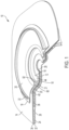
- a convex ostomy barrier 10 according to an embodiment is shown with a portion removed and viewed from a pouch-side to illustrate a layered construction of the convex ostomy barrier 10.
- the convex ostomy barrier 10 may be configured for a two-piece pouch system, and may generally comprise a skin barrier 12, a flange 16, a convex insert system 18, release liners 24, 26, and an inlet opening 28 for receiving a stoma.
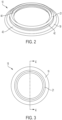
- FIGS. 2-5 are illustrations of the convex insert system 18 including a convex insert 19 and a ring 21 according to an embodiment.
- the convex insert 19 and the ring 21 may be configured to be assembled together to form the convex insert system 18 having a convex ring-like shaped body.
- the convex insert system 18 may be configured to provide the convexity of the convex ostomy barrier 10 to apply pressure around the peristomal area when the convex ostomy barrier 10 is attached to a user.
- the softness/hardness of the convex ostomy system 18 may be determined by the combined softness/hardness of the convex insert 19 and the ring 21. As such, the softness/hardness of the convex ostomy system 18 may be easily altered or controlled by incorporating a ring 21 having a different softness/hardness. Such a feature may provide significant cost savings since convex ostomy barriers 10 of various convexity hardness/softness may be manufactured by making and incorporating rings 21 of various softness/hardness, instead of making convex inserts of various softness/hardness.
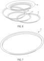
- the convex insert 19 is illustrated with three rings 21, 21', 21".
- Each of the rings 21, 21', 21" may be configured to have a different softness/hardness.
- a convex insert system prepared by assembling the convex insert 19 and the ring 21 may provide a first softness/hardness
- a convex insert system prepared by assembling the convex insert 19 and the ring 21' may provide a second softness/hardness that is different from the first softness/hardness
- a convex insert system prepared by assembling the convex insert 19 and the ring 21" may provide a third softness/hardness that is different from the first or second softness/hardness.
- the convex insert 19 may be configured to protrude axially toward a body-side direction and configured to receive the ring 21 as shown in FIGS. 2-5 .
- the convex insert 19 may include an outer flange 40, a middle portion 42, and an inner flange 44, and a radial wall 60 providing a generally flat pouch-side surface 64 on a pouch-side of the convex insert 19 for attachment of the flange 16.
- the outer flange 40 may include a concave body-side surface 50, which is configured to conform to a curved contour of a lower base portion 20 of a convex portion of the skin barrier 12.
- the radial wall 60 including the pouch-side surface 64 may be arranged in the middle portion 42.
- the middle portion 42 also may include a core-out portion 54 configured to receive the ring 21.
- the core-out portion 54 may be defined by the radial wall 60, which may radially extend from the outer flange 40 toward the inlet opening 28, and an axial wall 62, which may axially extend from the radial wall 60 toward a body-side direction.
- the inner flange 44 may radially extend from the axial wall 62 toward the inlet opening 28.
- the middle portion 42 may be configured to provide a step-like axial protrusion in the body-side direction from the outer flange 40 to the inner flange 44.
- the ring 21 may have a relatively thin ring-like body as shown in FIGS. 6 and 7 .
- the ring 21 may be configured such that the pouch-side of the ring 21 may fit in the core-out portion 54 of the convex insert 19 as best shown in FIGS. 4B60 and 5.
- the ring 21 may include a radial pouch-side surface 70 and an axial pouch-side surface 72, and a sloped body-side surface 74.
- the radial pouch-side surface 70 When received in the core-out portion 54 of the convex insert 19, the radial pouch-side surface 70 may be arranged adjacent the radial wall 60 of the convex insert 19 and the axial pouch-side surface 72 may be arranged adjacent the axial wall 72 of the convex insert 19.
- the body-side surface of the inner flange 44 of the convex insert 19, the sloped body-side surface 74 of the ring 21, and the body-side surface of the outer flange 49 of the convex insert 19 may form a generally continuous body-side surface of the convex insert system 18 as shown in FIG. 5 .
- the convex insert 19 and the ring 21 may be formed from the same or different materials. Suitable materials for the convex insert 19 and the ring 21 may include, but are not limited to, polymeric materials, rubber, silicone, and metallic materials.
- the convex insert 19 and the ring 21 may be formed from a heat sealable thermoplastic material, such as ethylene vinyl acetate (EVA), thermoplastic elastomer, or thermoplastic urethane.
- EVA ethylene vinyl acetate
- thermoplastic elastomer thermoplastic urethane
- the convex insert 19 and the ring 21 may be formed from a foam or silicone.
- the convex insert system 18 is used in the convex ostomy barrier 10 for a two-piece pouch system, which may include the flange 16 having a body-side coupling ring 22 for attaching an ostomy pouch.
- the convex insert system 18 including the convex insert 19 and the ring 21 may be used in a convex ostomy barrier for a one-piece pouch system.
- the body-side coupling ring 22 may be configured to mate with a pouch-side coupling ring (not shown), such that the ostomy pouch may be mechanically secured to the ostomy barrier 10 when the coupling rings are engaged with each other.
- the flange 16 may be attached to the convex insert 19 via a flange film 30.
- the flange 16 is attached to a pouch-side surface of the flange film 30 proximate an outer periphery of the flange film 30.
- the convex insert 19 may be attached to a body-side surface of the flange film 30 proximate an inner peripheral portion of the flange film 30, such that the flange 16 and the convex insert 19 are attached on the opposite surfaces of the flange film 30 at opposite ends.
- Such a configuration provides a floating flange feature, in which a user may insert his/her finger between the flange 16 and the convex insert 19 to facilitate engagement of the coupling rings to attach a pouch to the ostomy barrier 10.
- the skin barrier 12 may be arranged on the body-side surface of the ostomy barrier 10 for attachment to a user.
- the inlet opening 28 may be defined by an inner periphery of the skin barrier 12 for receiving a stoma (not shown.)
- the skin barrier 12 may be formed from a suitable medical-grade adhesive that can adhesively secure the ostomy barrier 10 to a patient's skin in the peristomal region, such as a hydrocolloid adhesive composition.
- the ostomy barrier 10 may also include a tape 14 including an adhesive layer 32 and a backing layer 34.
- the skin barrier 12 may include a backing layer 36 laminated on the pouch-side surface of the skin barrier 12.
- the backing layer 36 may be formed from a suitable heat sealable polymeric material, such that the backing layer 36 may be heat sealed to the tape 14.
- the skin barrier 12 is attached to a portion of the adhesive layer 32 proximate the inlet opening 28 with the backing layer 36 therebetween.
- an outer peripheral portion of the adhesive layer 32 may be attached to a user surrounding the skin barrier 12 to provide additional security.
- the ostomy barrier 10 may not include the tape 14.
- the skin barrier 12 may be the only means for attaching the ostomy barrier 10 to a user.
- the convex insert system 18 may be attached to the backing layer 34 of the tape 14 to provide a convexity to the skin barrier 12. In other embodiments, the convex insert system 18 may be attached to a pouch-side surface of the skin barrier 12.
- the flange film 30 may be attached to the pouch-side surface 64 of the convex insert 19 to secure the flange 16.
- the flange film 30 may be heat sealed to the pouch-side surface 64 of the convex insert 19.
- the body-side surfaces of the outer flange 40 of the convex insert 19, the sloped body-side surface 74 of the ring 21, and the body-side surface of the inner flange 44 of the convex insert 19 may be in contact with the tape 14, wherein at least some portions of which are attached to the backing layer 34.
- the body-side surface of the outer flange 40 may be heat sealed to the backing layer 34 of the tape 14.
- an adhesive may be provided on the body-side surface of the convex insert system 18 for attachment to the tape 14.
- a release liner may be provided to cover the skin barrier 12 and the tape 14.
- the release liner 24 is provided to cover an outer peripheral portion of the tape 14, and the release liner 26 is provided to cover the entire body-side surface of the ostomy barrier 10 including the skin barrier 12 and the tape 14.
- the release liner 26 may be removed first for attachment of the skin barrier 12 to peristomal skin, and the release liner 24 may be removed subsequently to expose the tape 14 for further attachment to user's skin.
Landscapes
- Health & Medical Sciences (AREA)
- Epidemiology (AREA)
- Nursing (AREA)
- Orthopedic Medicine & Surgery (AREA)
- Engineering & Computer Science (AREA)
- Biomedical Technology (AREA)
- Heart & Thoracic Surgery (AREA)
- Vascular Medicine (AREA)
- Life Sciences & Earth Sciences (AREA)
- Animal Behavior & Ethology (AREA)
- General Health & Medical Sciences (AREA)
- Public Health (AREA)
- Veterinary Medicine (AREA)
- Orthopedics, Nursing, And Contraception (AREA)
Description
- The following description generally relates to ostomy appliances, and in particular, to an ostomy barrier.
- Ostomy pouches for collecting bodily waste are used by individuals who have had surgery such as a colostomy, ileostomy, or urostomy. Two common types of ostomy pouch systems are available, to wit, a one-piece pouch system and a two-piece pouch system. In a one-piece pouch system, an ostomy barrier is permanently attached to a pouch. In such a one-piece pouch system, the entire pouch system including the ostomy barrier is removed when a user wants to replace the pouch.
- In a two-piece pouch system, a pouch and an ostomy barrier are provided as two separate devices. The two-piece pouch system typically includes a pair of coupling rings, one of which is fixedly attached to the ostomy barrier, while the other is attached to the pouch. The coupling rings are configured to mate with each other, such that the pouch may be securely and removeably attached to the ostomy barrier by engaging the coupling rings together. In use, the ostomy barrier is first attached to a user, and the pouch is secured to the faceplate by engaging the coupling rings together. Thus, two-piece pouch systems allow a user to remove and replace a pouch without removing the ostomy barrier from the user. This can help to reduce the discomfort and irritation associated with removing skin barrier adhesive from user's skin
- Ostomy barriers are configured to seal against peristomal skin surfaces and protect the peristomal surfaces from exposure to stomal effluent. However, the topography of stomas and peristomal surfaces surrounding stomas varies among patients, and sealing an ostomy appliance against such different peristomal surfaces and stomas remain as an area for further improvements. A person having a stoma that is flush or recessed may find that applying external support or pressure from a barrier in the peristomal region aids in directing the discharge of effluent from the stoma directly into the ostomy pouch. Accordingly, the effectiveness of an adhesive seal between the ostomy barrier and the peristomal skin surface (i.e., a seal formed by the adhesive layer) may be prolonged.
- The present disclosure provides an improved flexible convex barrier and a method of making convex barriers of various softness/hardness according to various embodiments.
-
WO2018093815A2 discloses a convex ostomy barrier includes a skin barrier, an inlet opening for receiving a stoma, and a convex insert. The convex insert includes an inner flange, an outer flange, and a middle portion arranged therebetween. The middle portion includes a pouch side surface for attaching a flange, a core-out portion configured to improve the flexibility of the convex insert, and a skin barrier support structure for supporting the skin barrier. - The present disclosure provides a convex ostomy barrier for attaching an ostomy appliance to a peristomal skin surrounding a stoma according to claim 1, and a method of making convex ostomy barriers of various softness/hardness according to claim 6. Advantageous features are provided in dependent claims.
- In one aspect, a convex ostomy barrier for attaching an ostomy appliance to a peristomal skin surrounding a stoma as set out in claim 1 is provided.
- In an embodiment, the convex insert may include a core-out portion configured to receive the ring. In such an embodiment, the ring may be arranged in the core-out portion of the convex insert to form the convex insert system having a convex ring-like body. The convex insert may include an inner flange, a middle portion including the core-out portion, and an outer flange. The inner flange and the outer flange may be connected by the middle portion and arranged in different axial planes, wherein the convex insert system is configured to support the skin barrier on a body-side surface. In an embodiment, the convex insert may include a radial wall radially extending from the outer flange toward the inlet opening and an axial wall extending axially from the radial wall in a body-side direction, wherein the core-out portion is defined by the radial wall and the axial wall on a body-side. The inner flange may extend from the axial wall toward the inlet opening, and wherein the outer flange, the middle portion, and the inner flange provides a step-like protrusion in the body-side direction.
- In some embodiments, the convex ostomy barrier may be configured for a two-piece ostomy pouch system comprising a flange including a coupling ring. The flange may be attached to a pouch-side surface of the radial wall of the convex insert.
- The convex ostomy barrier of any of the foregoing embodiments may be configured such that the convex ostomy barrier of various softness/hardness may be provided by using different rings in the convex insert system. For example, the convex ostomy barrier may be configured to have a first softness/hardness by incorporating the convex insert system formed from the convex insert and the ring having a first characteristic, or configured to have a second softness/hardness different than the first softness/hardness by incorporating the convex insert system formed from the convex insert and the ring having a second characteristic.
- In another aspect, a method of making convex ostomy barriers of various softness/hardness as set out in claim 6 is provided.
- In an embodiment, the plurality of the rings may include a first ring having a first characteristic and a second ring having a second characteristic. The convex insert may be assembled with the first ring to form a first convex insert system for a first convex ostomy barrier, or the convex insert may be assembled with the second ring to form a second convex insert system for a second convex ostomy barrier, wherein the first convex ostomy barrier has a first softness/hardness and the second convex ostomy barrier has a second softness/hardness that is different than the first softness/hardness.
- In some embodiments, the step of providing a convex insert and plurality of rings may include the step of providing the convex insert including a core-out portion configured to receive one of the plurality of rings. In such embodiments, the step of assembling the convex insert and the selected ring may comprise arranging the selected ring in the core-out portion of the convex insert to form the convex insert system having a convex ring-like body. The convex insert may include an inner flange, a middle portion including the core-out portion, and an outer flange, wherein the inner flange and the outer flange are connected by the middle portion and arranged in different axial planes. The convex insert system may be configured to support the skin barrier on a body-side surface.
- In an embodiment, the convex insert may include a radial wall radially extending from the outer flange toward the inlet opening and an axial wall extending axially from the radial wall in a body-side direction, wherein the core-out portion is defined by the radial wall and the axial wall on a body-side. The inner flange may extend from the axial wall toward the inlet opening, wherein the outer flange, the middle portion, and the inner flange provide a step-like protrusion in the body-side direction.
- The method of any of the foregoing embodiments may further include the step of providing a flange including a coupling ring, wherein the flange is attached to a pouch-side surface of the radial wall of the convex insert.
- Other aspects, objectives and advantages will become more apparent from the following detailed description when taken in conjunction with the accompanying drawings.
- The benefits and advantages of the present embodiments will become more readily apparent to those of ordinary skill in the relevant art after reviewing the following detailed description and accompanying drawings, wherein:
-
FIG. 1 is a perspective view of a convex ostomy barrier including a convex insert system according to an embodiment with a portion removed to illustrate its layered structure; -
FIG. 2 is a perspective view of a convex insert system including a convex insert and a ring according to an embodiment; -
FIG. 3 is a schematic top view of the convex insert system ofFIG. 2 ; -
FIGS. 4A and 4B are schematic cross sectional views of the convex insert system ofFIG. 3 taken along 4-4; -
FIG. 5 is a schematic cross sectional view of the convex insert system ofFIGS. 4A and 4B showing the ring received in the convex insert; -
FIG. 6 is a perspective view of a convex insert and a plurality of rings according to an embodiment; and -
FIG. 7 is a perspective view of one of the rings ofFIG. 6 . - While the present disclosure is susceptible of embodiment in various forms, there is shown in the drawings and will hereinafter be described a presently preferred embodiment with the understanding that the present disclosure is to be considered an exemplification and is not intended to limit the disclosure to the specific embodiment illustrated.
- Referring to
FIG. 1 , aconvex ostomy barrier 10 according to an embodiment is shown with a portion removed and viewed from a pouch-side to illustrate a layered construction of theconvex ostomy barrier 10. Theconvex ostomy barrier 10 may be configured for a two-piece pouch system, and may generally comprise askin barrier 12, a flange 16, aconvex insert system 18,release liners -
FIGS. 2-5 are illustrations of theconvex insert system 18 including aconvex insert 19 and aring 21 according to an embodiment. Theconvex insert 19 and thering 21 may be configured to be assembled together to form theconvex insert system 18 having a convex ring-like shaped body. The convexinsert system 18 may be configured to provide the convexity of theconvex ostomy barrier 10 to apply pressure around the peristomal area when theconvex ostomy barrier 10 is attached to a user. - The softness/hardness of the
convex ostomy system 18 may be determined by the combined softness/hardness of theconvex insert 19 and thering 21. As such, the softness/hardness of theconvex ostomy system 18 may be easily altered or controlled by incorporating aring 21 having a different softness/hardness. Such a feature may provide significant cost savings sinceconvex ostomy barriers 10 of various convexity hardness/softness may be manufactured by making and incorporatingrings 21 of various softness/hardness, instead of making convex inserts of various softness/hardness. - In
FIG. 6 , theconvex insert 19 is illustrated with threerings rings convex insert 19 and thering 21 may provide a first softness/hardness, and a convex insert system prepared by assembling theconvex insert 19 and the ring 21' may provide a second softness/hardness that is different from the first softness/hardness, and a convex insert system prepared by assembling theconvex insert 19 and thering 21" may provide a third softness/hardness that is different from the first or second softness/hardness. - The
convex insert 19 may be configured to protrude axially toward a body-side direction and configured to receive thering 21 as shown inFIGS. 2-5 . Theconvex insert 19 may include anouter flange 40, a middle portion 42, and aninner flange 44, and aradial wall 60 providing a generally flat pouch-side surface 64 on a pouch-side of theconvex insert 19 for attachment of the flange 16. Theouter flange 40 may include a concave body-side surface 50, which is configured to conform to a curved contour of a lower base portion 20 of a convex portion of theskin barrier 12. Theradial wall 60 including the pouch-side surface 64 may be arranged in the middle portion 42. The middle portion 42 also may include a core-out portion 54 configured to receive thering 21. The core-out portion 54 may be defined by theradial wall 60, which may radially extend from theouter flange 40 toward theinlet opening 28, and anaxial wall 62, which may axially extend from theradial wall 60 toward a body-side direction. Theinner flange 44 may radially extend from theaxial wall 62 toward theinlet opening 28. The middle portion 42 may be configured to provide a step-like axial protrusion in the body-side direction from theouter flange 40 to theinner flange 44. - The
ring 21 may have a relatively thin ring-like body as shown inFIGS. 6 and 7 . Thering 21 may be configured such that the pouch-side of thering 21 may fit in the core-out portion 54 of theconvex insert 19 as best shown in FIGS. 4B60
and 5. In an embodiment, thering 21 may include a radial pouch-side surface 70 and an axial pouch-side surface 72, and a sloped body-side surface 74. When received in the core-out portion 54 of theconvex insert 19, the radial pouch-side surface 70 may be arranged adjacent theradial wall 60 of theconvex insert 19 and the axial pouch-side surface 72 may be arranged adjacent the axial wall 72 of theconvex insert 19. In such an embodiment, the body-side surface of theinner flange 44 of theconvex insert 19, the sloped body-side surface 74 of thering 21, and the body-side surface of the outer flange 49 of theconvex insert 19 may form a generally continuous body-side surface of theconvex insert system 18 as shown inFIG. 5 . - The
convex insert 19 and thering 21 may be formed from the same or different materials. Suitable materials for theconvex insert 19 and thering 21 may include, but are not limited to, polymeric materials, rubber, silicone, and metallic materials. For example, theconvex insert 19 and thering 21 may be formed from a heat sealable thermoplastic material, such as ethylene vinyl acetate (EVA), thermoplastic elastomer, or thermoplastic urethane. In another example, theconvex insert 19 and thering 21 may be formed from a foam or silicone. - In
FIG. 1 , theconvex insert system 18 is used in theconvex ostomy barrier 10 for a two-piece pouch system, which may include the flange 16 having a body-side coupling ring 22 for attaching an ostomy pouch. In other embodiments, theconvex insert system 18 including theconvex insert 19 and thering 21 may be used in a convex ostomy barrier for a one-piece pouch system. The body-side coupling ring 22 may be configured to mate with a pouch-side coupling ring (not shown), such that the ostomy pouch may be mechanically secured to theostomy barrier 10 when the coupling rings are engaged with each other. The flange 16 may be attached to theconvex insert 19 via aflange film 30. In the embodiment ofFIG. 1 , the flange 16 is attached to a pouch-side surface of theflange film 30 proximate an outer periphery of theflange film 30. Theconvex insert 19 may be attached to a body-side surface of theflange film 30 proximate an inner peripheral portion of theflange film 30, such that the flange 16 and theconvex insert 19 are attached on the opposite surfaces of theflange film 30 at opposite ends. Such a configuration provides a floating flange feature, in which a user may insert his/her finger between the flange 16 and theconvex insert 19 to facilitate engagement of the coupling rings to attach a pouch to theostomy barrier 10. - The
skin barrier 12 may be arranged on the body-side surface of theostomy barrier 10 for attachment to a user. Theinlet opening 28 may be defined by an inner periphery of theskin barrier 12 for receiving a stoma (not shown.) Theskin barrier 12 may be formed from a suitable medical-grade adhesive that can adhesively secure theostomy barrier 10 to a patient's skin in the peristomal region, such as a hydrocolloid adhesive composition. - The
ostomy barrier 10 may also include atape 14 including anadhesive layer 32 and abacking layer 34. In some embodiments, theskin barrier 12 may include a backing layer 36 laminated on the pouch-side surface of theskin barrier 12. The backing layer 36 may be formed from a suitable heat sealable polymeric material, such that the backing layer 36 may be heat sealed to thetape 14. - In the embodiment of
FIG. 1 , theskin barrier 12 is attached to a portion of theadhesive layer 32 proximate the inlet opening 28 with the backing layer 36 therebetween. In such an embodiment, an outer peripheral portion of theadhesive layer 32 may be attached to a user surrounding theskin barrier 12 to provide additional security. - The
adhesive layer 32 of thetape 14 may be formed from a suitable medical adhesive, such as an acrylic adhesive. Thebacking layer 34 may be formed from a suitable material, such as a nonwoven material or a thin polymeric film. - In other embodiments, the
ostomy barrier 10 may not include thetape 14. In such an embodiment, theskin barrier 12 may be the only means for attaching theostomy barrier 10 to a user. - In the embodiment of
FIG. 1 , theconvex insert system 18 may be attached to thebacking layer 34 of thetape 14 to provide a convexity to theskin barrier 12. In other embodiments, theconvex insert system 18 may be attached to a pouch-side surface of theskin barrier 12. - In the embodiment of
FIG. 1 , theflange film 30 may be attached to the pouch-side surface 64 of theconvex insert 19 to secure the flange 16. For example, theflange film 30 may be heat sealed to the pouch-side surface 64 of theconvex insert 19. As shown inFIG. 1 , the body-side surfaces of theouter flange 40 of theconvex insert 19, the sloped body-side surface 74 of thering 21, and the body-side surface of theinner flange 44 of theconvex insert 19 may be in contact with thetape 14, wherein at least some portions of which are attached to thebacking layer 34. For example, the body-side surface of theouter flange 40 may be heat sealed to thebacking layer 34 of thetape 14. In another example, an adhesive may be provided on the body-side surface of theconvex insert system 18 for attachment to thetape 14. - A release liner may be provided to cover the
skin barrier 12 and thetape 14. In the embodiment ofFIG. 1 , therelease liner 24 is provided to cover an outer peripheral portion of thetape 14, and therelease liner 26 is provided to cover the entire body-side surface of theostomy barrier 10 including theskin barrier 12 and thetape 14. In use, therelease liner 26 may be removed first for attachment of theskin barrier 12 to peristomal skin, and therelease liner 24 may be removed subsequently to expose thetape 14 for further attachment to user's skin. - In the present disclosure, the words "a" or "an" are to be taken to include both the singular and the plural. Conversely, any reference to plural items shall, where appropriate, include the singular.
- From the foregoing it will be observed that numerous modifications and variations can be effectuated without departing from the scope of the present invention. It is to be understood that no limitation with respect to the specific embodiments illustrated is intended or should be inferred. The disclosure is intended to cover by the appended claims all such modifications as fall within the scope of the claims.
Claims (11)
- A convex ostomy barrier (10) for attaching an ostomy appliance to a peristomal skin surrounding a stoma, the convex ostomy barrier comprising:a skin barrier (12) formed from a skin friendly adhesive;an inlet opening (28) for receiving a stoma; anda convex insert system (18) arranged adjacent the skin barrier and configured to provide a convex body-side contour of the convex ostomy barrier, wherein the convex insert system includes a convex insert (19) and a plurality of rings (21, 21', 21") including a first ring having a first characteristic and a second ring having a second characteristic, wherein the convex insert and one of the plurality of rings are configured to be assembled together to form the convex insert system, wherein the convex ostomy barrier (10) is configured to have a first softness/hardness comprising the convex insert system formed from the convex insert (19) and the first ring (21), wherein the convex ostomy barrier (10) is configured to have a second softness/hardness comprising the convex insert system formed from the convex insert (19) and the second ring (21'); wherein the first softness/hardness is different from the second softness/hardness and the first characteristic is different from the second characteristic.
- The convex ostomy barrier (10) of claim 1, wherein the convex insert (19) includes a portion (54) configured to receive the ring (21, 21', 21"), wherein the ring is arranged in the portion (54) configured to receive the ring (21, 21', 21") of the convex insert to form the convex insert system having a convex ring like body.
- The convex ostomy barrier (10) of claim 2, wherein the convex insert comprises an inner flange (44), a middle portion (42) including the portion (54) configured to receive the ring (21, 21', 21"), and an outer flange (40), wherein the inner flange and the outer flange are connected by the middle portion and arranged in different axial planes, wherein the convex insert system is configured to support the skin barrier on a body-side surface.
- The convex ostomy barrier (10) of claim 3, wherein the convex insert includes a radial wall (60) radially extending from the outer flange toward the inlet opening, and an axial wall (62) extending axially from the radial wall in a body-side direction, wherein the portion (54) configured to receive the ring (21, 21', 21") is defined by the radial wall and the axial wall on a body-side, wherein the inner flange (44) extends from the axial wall toward the inlet opening, and wherein the outer flange (40), the middle portion (42), and the inner flange (44) provides a step-like protrusion in the body-side direction.
- The convex ostomy barrier (10) of any of claims 1-4, further comprising a flange (16) including a coupling ring (22), wherein the flange is attached to a pouch-side surface of the radial wall of the convex insert.
- A method of making convex ostomy barriers (10) of various softness/hardness, comprising the steps of:providing a convex insert (19) and a plurality of rings (21, 21', 21"), wherein the convex insert is configured to be assembled with one of the plurality of the rings to form a convex insert system (18), wherein each of the rings (21, 21', 21") has a different characteristic;selecting one of the plurality of the rings (21, 21', 21");assembling the convex insert (19) and the selected ring together to form the convex insert system (18); andattaching a skin barrier (12) to a body-side surface of the convex insert system;wherein the skin barrier is formed from a skin friendly adhesive;characterised in that the selected ring is selected according to a desired hardness/softness of a convex ostomy barrier.
- The method of claim 6, wherein the plurality of the rings (21, 21', 21") includes a first ring having a first characteristic, a second ring having a second characteristic, wherein the convex insert (19) is assembled with the first ring to form a first convex insert system for a first convex ostomy barrier; wherein the convex insert (19) is assembled with the second ring to form a second convex insert system for a second convex ostomy barrier; wherein the first convex ostomy barrier has a first softness/hardness, and the second convex ostomy barrier has a second softness/hardness, wherein the first softness/hardness is different than the second softness/hardness.
- The method of any of claims 6-7 wherein the step of providing a convex insert (19) and plurality of rings (21, 21', 21") comprises providing the convex insert including a portion (54) configured to receive the ring (21, 21', 21") which is configured to receive one of the plurality of rings, wherein the step of assembling the convex insert and the selected ring comprises arranging the selected ring in the portion (54) configured to receive the ring (21, 21', 21") of the convex insert to form the convex insert system (18) having a convex ring like body.
- The method of claim 8, wherein the convex insert comprises an inner flange (44), a middle portion (42) including the portion (54) configured to receive the ring (21, 21', 21"), and an outer flange (40), wherein the inner flange and the outer flange are connected by the middle portion and arranged in different axial planes, wherein the convex insert system is configured to support the skin barrier (12) on a body-side surface.
- The method of claim 9, wherein the convex insert (19) includes a radial wall (60) radially extending from the outer flange toward the inlet opening, and an axial wall (62) extending axially from the radial wall in a body-side direction, wherein the portion (54) configured to receive the ring (21, 21', 21")is defined by the radial wall and the axial wall on a body-side, wherein the inner flange extends from the axial wall toward the inlet opening, and wherein the outer flange, the middle portion, and the inner flange provide a step-like protrusion in the body-side direction.
- The method of claim 10, further comprising the step of providing a flange (16) including a coupling ring (22), wherein the flange is attached to a pouch-side surface of the radial wall of the convex insert.
Priority Applications (1)
| Application Number | Priority Date | Filing Date | Title |
|---|---|---|---|
| EP25158076.7A EP4534051A3 (en) | 2018-09-12 | 2019-09-11 | Convex ostomy barrier and method of forming convex ostomy barriers of various softness |
Applications Claiming Priority (2)
| Application Number | Priority Date | Filing Date | Title |
|---|---|---|---|
| US201862730109P | 2018-09-12 | 2018-09-12 | |
| PCT/US2019/050607 WO2020055998A1 (en) | 2018-09-12 | 2019-09-11 | Convex ostomy barrier and method of forming convex ostomy barriers of various softness |
Related Child Applications (2)
| Application Number | Title | Priority Date | Filing Date |
|---|---|---|---|
| EP25158076.7A Division EP4534051A3 (en) | 2018-09-12 | 2019-09-11 | Convex ostomy barrier and method of forming convex ostomy barriers of various softness |
| EP25158076.7A Division-Into EP4534051A3 (en) | 2018-09-12 | 2019-09-11 | Convex ostomy barrier and method of forming convex ostomy barriers of various softness |
Publications (2)
| Publication Number | Publication Date |
|---|---|
| EP3849480A1 EP3849480A1 (en) | 2021-07-21 |
| EP3849480B1 true EP3849480B1 (en) | 2025-04-02 |
Family
ID=68051997
Family Applications (2)
| Application Number | Title | Priority Date | Filing Date |
|---|---|---|---|
| EP19773690.3A Active EP3849480B1 (en) | 2018-09-12 | 2019-09-11 | Convex ostomy barrier and method of forming convex ostomy barriers of various softness |
| EP25158076.7A Pending EP4534051A3 (en) | 2018-09-12 | 2019-09-11 | Convex ostomy barrier and method of forming convex ostomy barriers of various softness |
Family Applications After (1)
| Application Number | Title | Priority Date | Filing Date |
|---|---|---|---|
| EP25158076.7A Pending EP4534051A3 (en) | 2018-09-12 | 2019-09-11 | Convex ostomy barrier and method of forming convex ostomy barriers of various softness |
Country Status (7)
| Country | Link |
|---|---|
| US (2) | US12048642B2 (en) |
| EP (2) | EP3849480B1 (en) |
| AU (1) | AU2019338387B2 (en) |
| DK (1) | DK3849480T3 (en) |
| HU (1) | HUE071753T2 (en) |
| LT (1) | LT3849480T (en) |
| WO (1) | WO2020055998A1 (en) |
Families Citing this family (17)
| Publication number | Priority date | Publication date | Assignee | Title |
|---|---|---|---|---|
| CA2683868A1 (en) | 2007-04-24 | 2008-11-06 | Bristol-Myers Squibb Company | Closure system for a drainable pouch |
| CA2689582C (en) | 2007-06-12 | 2016-08-09 | Convatec Technologies Inc. | Ostomy appliance |
| US10285847B2 (en) | 2011-09-29 | 2019-05-14 | Convatec Technologies Inc. | Ostomy pouch with filtering system |
| KR20160147898A (en) | 2014-04-24 | 2016-12-23 | 컨바텍 테크놀러지스 인크 | Ostomy pouch filter system |
| MX2020004744A (en) | 2017-11-09 | 2020-08-13 | 11 Health And Tech Limited | Ostomy monitoring system and method. |
| USD893514S1 (en) | 2018-11-08 | 2020-08-18 | 11 Health And Technologies Limited | Display screen or portion thereof with graphical user interface |
| AR116065A1 (en) | 2019-02-06 | 2021-03-31 | Consejo Nacional De Investigaciones Cientificas Y Tecn Conicet | NEUTRON DETECTOR AND GAMMA RADIATION USING A CHERENKOV DETECTOR IN WATER |
| EP3692956A1 (en) * | 2019-02-07 | 2020-08-12 | ConvaTec Technologies Inc. | Adjustable convex ostomy device |
| CN114007558B (en) | 2019-04-25 | 2024-08-02 | 康沃特克科技公司 | Ostomy wafer with adhesive and foam layer combined, ostomy device comprising such an ostomy wafer and method of application |
| JP7458416B2 (en) | 2019-04-25 | 2024-03-29 | コンバテック・テクノロジーズ・インコーポレイテッド | Ostomy wafer incorporating adhesive, ostomy device including ostomy wafer, and method of contacting ostomy wafer and ostomy device |
| US11679020B2 (en) | 2019-04-25 | 2023-06-20 | Convatec Technologies, Inc. | Perforated chamber ostomy wafers, ostomy devices including the same, and methods of applying ostomy wafers and ostomy devices |
| AU2021361238A1 (en) | 2020-10-15 | 2023-05-25 | Convatec Technologies Inc. | Ostomy systems and methods |
| US12258692B2 (en) * | 2022-03-01 | 2025-03-25 | Elc Management Llc | Cosmetic sheet masks for improved product delivery |
| WO2024050157A1 (en) * | 2022-09-01 | 2024-03-07 | Hollister Incorporated | Ostomy appliance with customizable barrier ring for localized convex support |
| AU2023248157B1 (en) * | 2022-09-01 | 2023-12-14 | Hollister Incorporated | Ostomy appliance with customizable barrier ring for localized convex support |
| AU2023219842B1 (en) * | 2022-09-01 | 2023-10-05 | Hollister Incorporated | Ostomy appliance for providing customized and localized convex support |
| WO2025151316A1 (en) * | 2024-01-08 | 2025-07-17 | Hollister Incorporated | Ostomy barrier appliance including floating convex insert |
Citations (6)
| Publication number | Priority date | Publication date | Assignee | Title |
|---|---|---|---|---|
| WO1993018725A1 (en) | 1992-03-20 | 1993-09-30 | Coloplast A/S | A convex ring |
| EP0415282B1 (en) * | 1989-08-28 | 1995-11-08 | E.R. SQUIBB & SONS, INC. | Ostomy device with convex adhesive faceplate and protective shield and method for fabricating same |
| WO1999030653A1 (en) | 1997-12-18 | 1999-06-24 | Bristol-Myers Squibb Company | Convex insert system for an ostomy appliance |
| US20030088219A1 (en) | 2001-11-05 | 2003-05-08 | Metz Michael A | Snap-in insert for convex ostomy faceplate |
| WO2018067539A1 (en) | 2016-10-03 | 2018-04-12 | Hollister Incorporated | Adjustable convexity ostomy barrier |
| WO2018093815A2 (en) | 2016-11-15 | 2018-05-24 | Hollister Incorporated | Convex ostomy barrier |
Family Cites Families (6)
| Publication number | Priority date | Publication date | Assignee | Title |
|---|---|---|---|---|
| GB1553450A (en) * | 1977-04-18 | 1979-09-26 | Squibb & Sons Inc | Ostomy bag |
| FI67297C (en) * | 1983-06-30 | 1985-03-11 | Hantaaki Oy | FISTELPAOSE |
| DK172791B1 (en) * | 1997-05-26 | 1999-07-19 | Coloplast As | An ostomy appliance |
| GB9929517D0 (en) * | 1999-12-13 | 2000-02-09 | Bristol Myers Squibb Co | Ostomy coupling |
| EP2002811A1 (en) * | 2007-06-12 | 2008-12-17 | BioTap A/S | Coupling device and drainage assembly for collecting bodily waste excreted from a body drainage exit, and method of using the coupling and drainage assembly |
| EP3692956A1 (en) * | 2019-02-07 | 2020-08-12 | ConvaTec Technologies Inc. | Adjustable convex ostomy device |
-
2019
- 2019-09-11 HU HUE19773690A patent/HUE071753T2/en unknown
- 2019-09-11 WO PCT/US2019/050607 patent/WO2020055998A1/en not_active Ceased
- 2019-09-11 EP EP19773690.3A patent/EP3849480B1/en active Active
- 2019-09-11 US US17/263,039 patent/US12048642B2/en active Active
- 2019-09-11 DK DK19773690.3T patent/DK3849480T3/en active
- 2019-09-11 EP EP25158076.7A patent/EP4534051A3/en active Pending
- 2019-09-11 LT LTEPPCT/US2019/050607T patent/LT3849480T/en unknown
- 2019-09-11 AU AU2019338387A patent/AU2019338387B2/en active Active
-
2024
- 2024-06-28 US US18/758,303 patent/US20240350296A1/en active Pending
Patent Citations (6)
| Publication number | Priority date | Publication date | Assignee | Title |
|---|---|---|---|---|
| EP0415282B1 (en) * | 1989-08-28 | 1995-11-08 | E.R. SQUIBB & SONS, INC. | Ostomy device with convex adhesive faceplate and protective shield and method for fabricating same |
| WO1993018725A1 (en) | 1992-03-20 | 1993-09-30 | Coloplast A/S | A convex ring |
| WO1999030653A1 (en) | 1997-12-18 | 1999-06-24 | Bristol-Myers Squibb Company | Convex insert system for an ostomy appliance |
| US20030088219A1 (en) | 2001-11-05 | 2003-05-08 | Metz Michael A | Snap-in insert for convex ostomy faceplate |
| WO2018067539A1 (en) | 2016-10-03 | 2018-04-12 | Hollister Incorporated | Adjustable convexity ostomy barrier |
| WO2018093815A2 (en) | 2016-11-15 | 2018-05-24 | Hollister Incorporated | Convex ostomy barrier |
Non-Patent Citations (1)
| Title |
|---|
| ANONYMOUS: "characteristic (definition)", MERRIAM-WEBSTER, 1 January 2025 (2025-01-01), XP093355961, Retrieved from the Internet <URL:https://www.merriam-webster.com/dictionary/characteristic> |
Also Published As
| Publication number | Publication date |
|---|---|
| AU2019338387A1 (en) | 2021-02-18 |
| WO2020055998A1 (en) | 2020-03-19 |
| CA3108574A1 (en) | 2020-03-19 |
| US20210307952A1 (en) | 2021-10-07 |
| DK3849480T3 (en) | 2025-04-22 |
| EP4534051A3 (en) | 2025-06-11 |
| US20240350296A1 (en) | 2024-10-24 |
| AU2019338387B2 (en) | 2024-07-18 |
| LT3849480T (en) | 2025-05-26 |
| EP3849480A1 (en) | 2021-07-21 |
| EP4534051A2 (en) | 2025-04-09 |
| HUE071753T2 (en) | 2025-09-28 |
| US12048642B2 (en) | 2024-07-30 |
Similar Documents
| Publication | Publication Date | Title |
|---|---|---|
| EP3849480B1 (en) | Convex ostomy barrier and method of forming convex ostomy barriers of various softness | |
| AU2017359661B2 (en) | Convex ostomy barrier | |
| AU2017362258B2 (en) | Ostomy barrier | |
| AU2017339905B2 (en) | Adjustable convexity ostomy barrier | |
| EP2496193B1 (en) | Seal for an ostomy appliance | |
| EP2768442B1 (en) | Attachment mechanism for ostomy bags | |
| EP3445296B1 (en) | Ostomy barrier | |
| CA3108574C (en) | Convex ostomy barrier and method of forming convex ostomy barriers of various softness | |
| US12097142B2 (en) | Ostomy appliance with customizable barrier ring for localized convex support | |
| GB2311469A (en) | Ostomy bag and coupling element | |
| AU2024288291A1 (en) | Convex ostomy barrier with flexible support convexity | |
| WO2025259495A1 (en) | Concave barrier ring or strip |
Legal Events
| Date | Code | Title | Description |
|---|---|---|---|
| STAA | Information on the status of an ep patent application or granted ep patent |
Free format text: STATUS: UNKNOWN |
|
| STAA | Information on the status of an ep patent application or granted ep patent |
Free format text: STATUS: THE INTERNATIONAL PUBLICATION HAS BEEN MADE |
|
| PUAI | Public reference made under article 153(3) epc to a published international application that has entered the european phase |
Free format text: ORIGINAL CODE: 0009012 |
|
| STAA | Information on the status of an ep patent application or granted ep patent |
Free format text: STATUS: REQUEST FOR EXAMINATION WAS MADE |
|
| 17P | Request for examination filed |
Effective date: 20210127 |
|
| AK | Designated contracting states |
Kind code of ref document: A1 Designated state(s): AL AT BE BG CH CY CZ DE DK EE ES FI FR GB GR HR HU IE IS IT LI LT LU LV MC MK MT NL NO PL PT RO RS SE SI SK SM TR |
|
| DAV | Request for validation of the european patent (deleted) | ||
| DAX | Request for extension of the european patent (deleted) | ||
| STAA | Information on the status of an ep patent application or granted ep patent |
Free format text: STATUS: EXAMINATION IS IN PROGRESS |
|
| 17Q | First examination report despatched |
Effective date: 20230117 |
|
| P01 | Opt-out of the competence of the unified patent court (upc) registered |
Effective date: 20230520 |
|
| GRAP | Despatch of communication of intention to grant a patent |
Free format text: ORIGINAL CODE: EPIDOSNIGR1 |
|
| STAA | Information on the status of an ep patent application or granted ep patent |
Free format text: STATUS: GRANT OF PATENT IS INTENDED |
|
| GRAS | Grant fee paid |
Free format text: ORIGINAL CODE: EPIDOSNIGR3 |
|
| GRAA | (expected) grant |
Free format text: ORIGINAL CODE: 0009210 |
|
| STAA | Information on the status of an ep patent application or granted ep patent |
Free format text: STATUS: THE PATENT HAS BEEN GRANTED |
|
| INTG | Intention to grant announced |
Effective date: 20250210 |
|
| AK | Designated contracting states |
Kind code of ref document: B1 Designated state(s): AL AT BE BG CH CY CZ DE DK EE ES FI FR GB GR HR HU IE IS IT LI LT LU LV MC MK MT NL NO PL PT RO RS SE SI SK SM TR |
|
| REG | Reference to a national code |
Ref country code: GB Ref legal event code: FG4D |
|
| REG | Reference to a national code |
Ref country code: CH Ref legal event code: EP |
|
| REG | Reference to a national code |
Ref country code: DK Ref legal event code: T3 Effective date: 20250414 |
|
| REG | Reference to a national code |
Ref country code: IE Ref legal event code: FG4D Ref country code: NL Ref legal event code: FP |
|
| REG | Reference to a national code |
Ref country code: DE Ref legal event code: R096 Ref document number: 602019068132 Country of ref document: DE |
|
| REG | Reference to a national code |
Ref country code: SE Ref legal event code: TRGR |
|
| REG | Reference to a national code |
Ref country code: AT Ref legal event code: MK05 Ref document number: 1780569 Country of ref document: AT Kind code of ref document: T Effective date: 20250402 |
|
| REG | Reference to a national code |
Ref country code: HU Ref legal event code: AG4A Ref document number: E071753 Country of ref document: HU |
|
| PG25 | Lapsed in a contracting state [announced via postgrant information from national office to epo] |
Ref country code: PT Free format text: LAPSE BECAUSE OF FAILURE TO SUBMIT A TRANSLATION OF THE DESCRIPTION OR TO PAY THE FEE WITHIN THE PRESCRIBED TIME-LIMIT Effective date: 20250804 Ref country code: ES Free format text: LAPSE BECAUSE OF FAILURE TO SUBMIT A TRANSLATION OF THE DESCRIPTION OR TO PAY THE FEE WITHIN THE PRESCRIBED TIME-LIMIT Effective date: 20250402 Ref country code: FI Free format text: LAPSE BECAUSE OF FAILURE TO SUBMIT A TRANSLATION OF THE DESCRIPTION OR TO PAY THE FEE WITHIN THE PRESCRIBED TIME-LIMIT Effective date: 20250402 |
|
| PGFP | Annual fee paid to national office [announced via postgrant information from national office to epo] |
Ref country code: DE Payment date: 20250929 Year of fee payment: 7 Ref country code: LT Payment date: 20250819 Year of fee payment: 7 Ref country code: DK Payment date: 20250925 Year of fee payment: 7 |
|
| PG25 | Lapsed in a contracting state [announced via postgrant information from national office to epo] |
Ref country code: NO Free format text: LAPSE BECAUSE OF FAILURE TO SUBMIT A TRANSLATION OF THE DESCRIPTION OR TO PAY THE FEE WITHIN THE PRESCRIBED TIME-LIMIT Effective date: 20250702 Ref country code: GR Free format text: LAPSE BECAUSE OF FAILURE TO SUBMIT A TRANSLATION OF THE DESCRIPTION OR TO PAY THE FEE WITHIN THE PRESCRIBED TIME-LIMIT Effective date: 20250703 |
|
| PG25 | Lapsed in a contracting state [announced via postgrant information from national office to epo] |
Ref country code: PL Free format text: LAPSE BECAUSE OF FAILURE TO SUBMIT A TRANSLATION OF THE DESCRIPTION OR TO PAY THE FEE WITHIN THE PRESCRIBED TIME-LIMIT Effective date: 20250402 |
|
| PGFP | Annual fee paid to national office [announced via postgrant information from national office to epo] |
Ref country code: NL Payment date: 20250926 Year of fee payment: 7 |
|
| PG25 | Lapsed in a contracting state [announced via postgrant information from national office to epo] |
Ref country code: BG Free format text: LAPSE BECAUSE OF FAILURE TO SUBMIT A TRANSLATION OF THE DESCRIPTION OR TO PAY THE FEE WITHIN THE PRESCRIBED TIME-LIMIT Effective date: 20250402 |
|
| PGFP | Annual fee paid to national office [announced via postgrant information from national office to epo] |
Ref country code: HU Payment date: 20250822 Year of fee payment: 7 Ref country code: GB Payment date: 20250929 Year of fee payment: 7 |
|
| PG25 | Lapsed in a contracting state [announced via postgrant information from national office to epo] |
Ref country code: HR Free format text: LAPSE BECAUSE OF FAILURE TO SUBMIT A TRANSLATION OF THE DESCRIPTION OR TO PAY THE FEE WITHIN THE PRESCRIBED TIME-LIMIT Effective date: 20250402 |
|
| PG25 | Lapsed in a contracting state [announced via postgrant information from national office to epo] |
Ref country code: AT Free format text: LAPSE BECAUSE OF FAILURE TO SUBMIT A TRANSLATION OF THE DESCRIPTION OR TO PAY THE FEE WITHIN THE PRESCRIBED TIME-LIMIT Effective date: 20250402 |
|
| PGFP | Annual fee paid to national office [announced via postgrant information from national office to epo] |
Ref country code: FR Payment date: 20250925 Year of fee payment: 7 |
|
| PGFP | Annual fee paid to national office [announced via postgrant information from national office to epo] |
Ref country code: SE Payment date: 20250927 Year of fee payment: 7 |
|
| PG25 | Lapsed in a contracting state [announced via postgrant information from national office to epo] |
Ref country code: RS Free format text: LAPSE BECAUSE OF FAILURE TO SUBMIT A TRANSLATION OF THE DESCRIPTION OR TO PAY THE FEE WITHIN THE PRESCRIBED TIME-LIMIT Effective date: 20250702 |
|
| PGFP | Annual fee paid to national office [announced via postgrant information from national office to epo] |
Ref country code: IE Payment date: 20250929 Year of fee payment: 7 |
|
| PG25 | Lapsed in a contracting state [announced via postgrant information from national office to epo] |
Ref country code: IS Free format text: LAPSE BECAUSE OF FAILURE TO SUBMIT A TRANSLATION OF THE DESCRIPTION OR TO PAY THE FEE WITHIN THE PRESCRIBED TIME-LIMIT Effective date: 20250802 |
|
| PG25 | Lapsed in a contracting state [announced via postgrant information from national office to epo] |
Ref country code: LV Free format text: LAPSE BECAUSE OF FAILURE TO SUBMIT A TRANSLATION OF THE DESCRIPTION OR TO PAY THE FEE WITHIN THE PRESCRIBED TIME-LIMIT Effective date: 20250402 |
|
| REG | Reference to a national code |
Ref country code: DE Ref legal event code: R026 Ref document number: 602019068132 Country of ref document: DE |
|
| PLBI | Opposition filed |
Free format text: ORIGINAL CODE: 0009260 |
|
| REG | Reference to a national code |
Ref country code: CH Ref legal event code: L10 Free format text: ST27 STATUS EVENT CODE: U-0-0-L10-L00 (AS PROVIDED BY THE NATIONAL OFFICE) Effective date: 20251231 |
|
| PLBI | Opposition filed |
Free format text: ORIGINAL CODE: 0009260 |
|
| PG25 | Lapsed in a contracting state [announced via postgrant information from national office to epo] |
Ref country code: SM Free format text: LAPSE BECAUSE OF FAILURE TO SUBMIT A TRANSLATION OF THE DESCRIPTION OR TO PAY THE FEE WITHIN THE PRESCRIBED TIME-LIMIT Effective date: 20250402 |
|
| REG | Reference to a national code |
Ref country code: CH Ref legal event code: L10 Free format text: ST27 STATUS EVENT CODE: U-0-0-L10-L00 (AS PROVIDED BY THE NATIONAL OFFICE) Effective date: 20260114 |
|
| PLAX | Notice of opposition and request to file observation + time limit sent |
Free format text: ORIGINAL CODE: EPIDOSNOBS2 |
|
| PG25 | Lapsed in a contracting state [announced via postgrant information from national office to epo] |
Ref country code: CZ Free format text: LAPSE BECAUSE OF FAILURE TO SUBMIT A TRANSLATION OF THE DESCRIPTION OR TO PAY THE FEE WITHIN THE PRESCRIBED TIME-LIMIT Effective date: 20250402 |
|
| PG25 | Lapsed in a contracting state [announced via postgrant information from national office to epo] |
Ref country code: EE Free format text: LAPSE BECAUSE OF FAILURE TO SUBMIT A TRANSLATION OF THE DESCRIPTION OR TO PAY THE FEE WITHIN THE PRESCRIBED TIME-LIMIT Effective date: 20250402 |
|
| PG25 | Lapsed in a contracting state [announced via postgrant information from national office to epo] |
Ref country code: RO Free format text: LAPSE BECAUSE OF FAILURE TO SUBMIT A TRANSLATION OF THE DESCRIPTION OR TO PAY THE FEE WITHIN THE PRESCRIBED TIME-LIMIT Effective date: 20250402 Ref country code: SK Free format text: LAPSE BECAUSE OF FAILURE TO SUBMIT A TRANSLATION OF THE DESCRIPTION OR TO PAY THE FEE WITHIN THE PRESCRIBED TIME-LIMIT Effective date: 20250402 |
|
| 26 | Opposition filed |
Opponent name: COLOPLAST A/S Effective date: 20251222 |
|
| PG25 | Lapsed in a contracting state [announced via postgrant information from national office to epo] |
Ref country code: IT Free format text: LAPSE BECAUSE OF FAILURE TO SUBMIT A TRANSLATION OF THE DESCRIPTION OR TO PAY THE FEE WITHIN THE PRESCRIBED TIME-LIMIT Effective date: 20250402 |
|
| 26 | Opposition filed |
Opponent name: SALTS HEALTHCARE LIMITED Effective date: 20260102 |