EP3849129B1 - Techniken zur anpassung von direktzugriffszeitline und -timing - Google Patents
Techniken zur anpassung von direktzugriffszeitline und -timing Download PDFInfo
- Publication number
- EP3849129B1 EP3849129B1 EP21159358.7A EP21159358A EP3849129B1 EP 3849129 B1 EP3849129 B1 EP 3849129B1 EP 21159358 A EP21159358 A EP 21159358A EP 3849129 B1 EP3849129 B1 EP 3849129B1
- Authority
- EP
- European Patent Office
- Prior art keywords
- numerology
- time
- random access
- uplink transmission
- base station
- Prior art date
- Legal status (The legal status is an assumption and is not a legal conclusion. Google has not performed a legal analysis and makes no representation as to the accuracy of the status listed.)
- Active
Links
Images







Classifications
-
- H—ELECTRICITY
- H04—ELECTRIC COMMUNICATION TECHNIQUE
- H04L—TRANSMISSION OF DIGITAL INFORMATION, e.g. TELEGRAPHIC COMMUNICATION
- H04L5/00—Arrangements affording multiple use of the transmission path
- H04L5/003—Arrangements for allocating sub-channels of the transmission path
- H04L5/0053—Allocation of signalling, i.e. of overhead other than pilot signals
-
- H—ELECTRICITY
- H04—ELECTRIC COMMUNICATION TECHNIQUE
- H04W—WIRELESS COMMUNICATION NETWORKS
- H04W56/00—Synchronisation arrangements
- H04W56/001—Synchronization between nodes
-
- H—ELECTRICITY
- H04—ELECTRIC COMMUNICATION TECHNIQUE
- H04L—TRANSMISSION OF DIGITAL INFORMATION, e.g. TELEGRAPHIC COMMUNICATION
- H04L27/00—Modulated-carrier systems
- H04L27/26—Systems using multi-frequency codes
- H04L27/2601—Multicarrier modulation systems
- H04L27/2647—Arrangements specific to the receiver only
- H04L27/2655—Synchronisation arrangements
- H04L27/2666—Acquisition of further OFDM parameters, e.g. bandwidth, subcarrier spacing, or guard interval length
-
- H—ELECTRICITY
- H04—ELECTRIC COMMUNICATION TECHNIQUE
- H04L—TRANSMISSION OF DIGITAL INFORMATION, e.g. TELEGRAPHIC COMMUNICATION
- H04L5/00—Arrangements affording multiple use of the transmission path
- H04L5/0091—Signalling for the administration of the divided path, e.g. signalling of configuration information
- H04L5/0092—Indication of how the channel is divided
-
- H—ELECTRICITY
- H04—ELECTRIC COMMUNICATION TECHNIQUE
- H04W—WIRELESS COMMUNICATION NETWORKS
- H04W56/00—Synchronisation arrangements
- H04W56/004—Synchronisation arrangements compensating for timing error of reception due to propagation delay
- H04W56/0045—Synchronisation arrangements compensating for timing error of reception due to propagation delay compensating for timing error by altering transmission time
-
- H—ELECTRICITY
- H04—ELECTRIC COMMUNICATION TECHNIQUE
- H04W—WIRELESS COMMUNICATION NETWORKS
- H04W56/00—Synchronisation arrangements
- H04W56/0055—Synchronisation arrangements determining timing error of reception due to propagation delay
-
- H—ELECTRICITY
- H04—ELECTRIC COMMUNICATION TECHNIQUE
- H04W—WIRELESS COMMUNICATION NETWORKS
- H04W74/00—Wireless channel access
- H04W74/08—Non-scheduled access, e.g. ALOHA
- H04W74/0833—Random access procedures, e.g. with 4-step access
-
- H—ELECTRICITY
- H04—ELECTRIC COMMUNICATION TECHNIQUE
- H04W—WIRELESS COMMUNICATION NETWORKS
- H04W74/00—Wireless channel access
- H04W74/002—Transmission of channel access control information
- H04W74/006—Transmission of channel access control information in the downlink, i.e. towards the terminal
Definitions
- the following relates generally to wireless communications, and more specifically to random access timeline and timing adjustment techniques.
- Wireless communications systems are widely deployed to provide various types of communication content such as voice, video, packet data, messaging, broadcast, and so on. These systems may be capable of supporting communication with multiple users by sharing the available system resources (e.g., time, frequency, and power).
- Examples of such multiple-access systems include fourth generation (4G) systems such as Long Term Evolution (LTE) systems, LTE-Advanced (LTE-A) systems, or LTE-A Pro systems, and fifth generation (5G) systems which may be referred to as New Radio (NR) systems.
- 4G systems such as Long Term Evolution (LTE) systems, LTE-Advanced (LTE-A) systems, or LTE-A Pro systems
- 5G systems which may be referred to as New Radio (NR) systems.
- a wireless multiple-access communications system may include a number of base stations or network access nodes, each simultaneously supporting communication for multiple communication devices, which may be otherwise known as user equipment (UE).
- UE user equipment
- a base station may transmit a downlink transmission to a UE and in response, the UE may transmit an uplink transmission.
- the UE may experience delays related to processing the downlink transmission and preparing the uplink transmission for transmission to the base station. These delays may vary based on UE capability, transmission types, amount of data received or transmitted, etc.
- the time gap between a received downlink transmission may be fixed based on a number of symbols or slots. However, the symbol duration and the slot duration may vary based on the numerology.
- WO 2018/021867 A1 discloses a method for receiving a reference signal (RS) by a user equipment (UE) in a wireless communication system, comprising: receiving a first RS through a first antenna port, and receiving a second RS through a second antenna port assumed to be quasi co-located (QCL) with the first antenna port, wherein the first and second antenna ports are QCL-assumed with respect to at least one QCL parameter, and the at least one QCL parameter may include a receiving beam-related parameter.
- RS reference signal
- UE user equipment
- WO 2017/088898 A1 discloses a method for beamforming training, comprising: transmitting, by a network node, common control signaling via a plurality of beams periodically according to a predetermined beam sweeping pattern, and transmitting, via a set of one or more beams in each of one or more sequential time-domain resources, an aperiodic downlink sounding burst to at least one user device to allow the at least one user device to perform beamforming training.
- the described techniques relate to improved methods, systems, devices, or apparatuses that support random access timeline and timing adjustment techniques.
- the described techniques provide for determining a minimum time gap between a downlink transmission and an uplink transmission.
- a minimum time gap between a downlink transmission and an uplink transmission may be specified based on a downlink decoding time, an uplink transmission preparation time, or a higher layer processing latency, each of which may depend on a numerology.
- Numerology may refer to a given subcarrier spacing (SCS) (i.e., the bandwidth between each tone or subcarrier in the frequency domain), symbol duration (i.e., the time interval designated as a single time resource), number of tones within a carrier (i.e., the number of subcarriers spanning a given component carrier (CC) for wireless communication), the number of symbols spanning a frame, subframe, slot, mini-slot, or any other time interval of the wireless network.
- the minimum time gap between reception of a physical downlink control channel (PDCCH) order and transmission of a random access channel (RACH) preamble (e.g., Msg1) may be determined or calculated based on one or more numerologies.
- the minimum time gap between reception of a timing advance (TA) command and a time-adjusted uplink transmission in response to the TA command may be determined or calculated based on one or more numerologies.
- TA timing advance
- the minimum time gap may be determined by a user equipment (UE) so as to allow the UE enough time to process the downlink transmission and generate the uplink transmission in response to the downlink transmission.
- the duration of the minimum time gap may be based on a downlink decoding time (N1), an uplink transmission preparation time (N2), or a higher layer processing latency (L2), each of which may depend on a numerology.
- the downlink transmission may be a transmission on physical downlink control channel (PDCCH) that orders a UE to start a random access channel (RACH) procedure (i.e., PDCCH order).
- PDCCH physical downlink control channel
- RACH random access channel
- the uplink response transmission may be a RACH preamble (e.g., Msg1), and the UE may wait a minimum time gap to process the RACH order and generate the RACH preamble.
- the downlink transmission may be a timing advance (TA) command.
- TA timing advance
- a UE may adjust its uplink transmission timing based on the TA command to align the uplink transmission timings at a base station. In such a case, the UE may wait a minimum time gap before applying the TA command to uplink transmissions.
- N1 may be based on a numerology associated with PDCCH, a numerology associated with the downlink bandwidth part where PDCCH is received, any numerology configured by a higher layer solely to determine the minimum time gap, or any default numerology (e.g., a numerology associated with a 15 kilohertz (kHz) subcarrier spacing (SCS)).
- N2 may be defined based on a numerology associated with a RACH preamble, a numerology associated with the uplink bandwidth part where a physical RACH (PRACH) is transmitted, any numerology configured by a higher layer solely to determine the minimum time gap, or any default numerology (e.g., a numerology associated with a 15 kHz SCS).
- PRACH physical RACH
- N1 and N2 may be associated with a numerology for which N1 and N2 are not defined (e.g., a numerology associated with a 1.25 kHz SCS or a 5 kHz SCS). In such a case, N1 and N2 may be defined according to a default numerology (e.g., a numerology associated with a 15 kHz SCS). In some instances, L2 may be defined according to a numerology associated with a higher layer processing latency. L2 may have a fixed duration across all numerologies (e.g., 0.5 milliseconds (ms)).
- ms milliseconds
- the minimum time gap may be based on N1, N2, and L2.
- the minimum time gap may be the duration of N1 only, the duration of N2 only, the duration of N1 + N2, the duration of N1 + N2 + L2, or the maximum value (e.g., in absolute time) of N1 and N2.
- FIG. 1 illustrates an example of a wireless communications system 100 in accordance with various aspects of the present disclosure.
- the wireless communications system 100 includes base stations 105, UEs 115, and a core network 130.
- the wireless communications system 100 may be a Long Term Evolution (LTE) network, an LTE-Advanced (LTE-A) network, an LTE-A Pro network, or a New Radio (NR) network.
- LTE Long Term Evolution
- LTE-A LTE-Advanced
- LTE-A Pro LTE-A Pro
- NR New Radio
- wireless communications system 100 may support enhanced broadband communications, ultra-reliable (e.g., mission critical) communications, low latency communications, or communications with low-cost and low-complexity devices.
- ultra-reliable e.g., mission critical
- Base stations 105 may wirelessly communicate with UEs 115 via one or more base station antennas.
- Base stations 105 described herein may include or may be referred to by those skilled in the art as a base transceiver station, a radio base station, an access point, a radio transceiver, a NodeB, an eNodeB (eNB), a next-generation NodeB or giga-NodeB (either of which may be referred to as a gNB), a Home NodeB, a Home eNodeB, or some other suitable terminology.
- Wireless communications system 100 may include base stations 105 of different types (e.g., macro or small cell base stations 105).
- the UEs 115 described herein may be able to communicate with various types of base stations 105 and network equipment including macro eNBs, small cell eNBs, gNBs, relay base stations 105, and the like.
- Each base station 105 may be associated with a particular geographic coverage area 110 in which communications with various UEs 115 is supported. Each base station 105 may provide communication coverage for a respective geographic coverage area 110 via communication links 125, and communication links 125 between a base station 105 and a UE 115 may utilize one or more carriers. Communication links 125 shown in wireless communications system 100 may include uplink transmissions from a UE 115 to a base station 105, or downlink transmissions from a base station 105 to a UE 115. Downlink transmissions may also be called forward link transmissions while uplink transmissions may also be called reverse link transmissions.
- the geographic coverage area 110 for a base station 105 may be divided into sectors making up only a portion of the geographic coverage area 110, and each sector may be associated with a cell.
- each base station 105 may provide communication coverage for a macro cell, a small cell, a hot spot, or other types of cells, or various combinations thereof.
- a base station 105 may be movable and therefore provide communication coverage for a moving geographic coverage area 110.
- different geographic coverage areas 110 associated with different technologies may overlap, and overlapping geographic coverage areas 110 associated with different technologies may be supported by the same base station 105 or by different base stations 105.
- the wireless communications system 100 may include, for example, a heterogeneous LTE/LTE-A/LTE-A Pro or NR network in which different types of base stations 105 provide coverage for various geographic coverage areas 110.
- UEs 115 may be dispersed throughout the wireless communications system 100, and each UE 115 may be stationary or mobile.
- a UE 115 may also be referred to as a mobile device, a wireless device, a remote device, a handheld device, or a subscriber device, or some other suitable terminology, where the "device” may also be referred to as a unit, a station, a terminal, or a client.
- a UE 115 may also be a personal electronic device such as a cellular phone, a personal digital assistant (PDA), a tablet computer, a laptop computer, or a personal computer.
- PDA personal digital assistant
- a UE 115 may also refer to a wireless local loop (WLL) station, an Internet of Things (IoT) device, an Internet of Everything (IoE) device, or an MTC device, or the like, which may be implemented in various articles such as appliances, vehicles, meters, or the like.
- WLL wireless local loop
- IoT Internet of Things
- IoE Internet of Everything
- MTC massive machine type communications
- Some UEs 115 may be low cost or low complexity devices, and may provide for automated communication between machines (e.g., via Machine-to-Machine (M2M) communication).
- M2M communication or MTC may refer to data communication technologies that allow devices to communicate with one another or a base station 105 without human intervention.
- M2M communication or MTC may include communications from devices that integrate sensors or meters to measure or capture information and relay that information to a central server or application program that can make use of the information or present the information to humans interacting with the program or application.
- Some UEs 115 may be designed to collect information or enable automated behavior of machines. Examples of applications for MTC devices include smart metering, inventory monitoring, water level monitoring, equipment monitoring, healthcare monitoring, wildlife monitoring, weather and geological event monitoring, fleet management and tracking, remote security sensing, physical access control, and transaction-based business charging.
- Some UEs 115 may be configured to employ operating modes that reduce power consumption, such as half-duplex communications (e.g., a mode that supports one-way communication via transmission or reception, but not transmission and reception simultaneously). In some examples half-duplex communications may be performed at a reduced peak rate. Other power conservation techniques for UEs 115 include entering a power saving "deep sleep" mode when not engaging in active communications, or operating over a limited bandwidth (e.g., according to narrowband communications). In some cases, UEs 115 may be designed to support critical functions (e.g., mission critical functions), and a wireless communications system 100 may be configured to provide ultra-reliable communications for these functions.
- critical functions e.g., mission critical functions
- a UE 115 may also be able to communicate directly with other UEs 115 (e.g., using a peer-to-peer (P2P) or device-to-device (D2D) protocol).
- P2P peer-to-peer
- D2D device-to-device
- One or more of a group of UEs 115 utilizing D2D communications may be within the geographic coverage area 110 of a base station 105.
- Other UEs 115 in such a group may be outside the geographic coverage area 110 of a base station 105, or be otherwise unable to receive transmissions from a base station 105.
- groups of UEs 115 communicating via D2D communications may utilize a one-to-many (1:M) system in which each UE 115 transmits to every other UE 115 in the group.
- a base station 105 facilitates the scheduling of resources for D2D communications.
- D2D communications are carried out between UEs 115 without the involvement of a base station
- Base stations 105 may communicate with the core network 130 and with one another. For example, base stations 105 may interface with the core network 130 through backhaul links 132 (e.g., via an S1 or other interface). Base stations 105 may communicate with one another over backhaul links 134 (e.g., via an X2 or other interface) either directly (e.g., directly between base stations 105) or indirectly (e.g., via core network 130).
- backhaul links 132 e.g., via an S1 or other interface
- backhaul links 134 e.g., via an X2 or other interface
- the core network 130 may provide user authentication, access authorization, tracking, Internet Protocol (IP) connectivity, and other access, routing, or mobility functions.
- the core network 130 may be an evolved packet core (EPC), which may include at least one mobility management entity (MME), at least one serving gateway (S-GW), and at least one Packet Data Network (PDN) gateway (P-GW).
- the MME may manage non-access stratum (e.g., control plane) functions such as mobility, authentication, and bearer management for UEs 115 served by base stations 105 associated with the EPC.
- User IP packets may be transferred through the S-GW, which itself may be connected to the P-GW.
- the P-GW may provide IP address allocation as well as other functions.
- the P-GW may be connected to the network operators IP services.
- the operators IP services may include access to the Internet, Intranet(s), an IP Multimedia Subsystem (IMS), or a Packet-Switched (PS) Streaming Service.
- IMS IP Multimedia Subsystem
- At least some of the network devices may include subcomponents such as an access network entity, which may be an example of an access node controller (ANC).
- an access network entity may communicate with UEs 115 through a number of other access network transmission entities, which may be referred to as a radio head, a smart radio head, or a transmission reception point (TRP).
- TRP transmission reception point
- various functions of each access network entity or base station 105 may be distributed across various network devices (e.g., radio heads and ANCs) or consolidated into a single network device (e.g., a base station 105).
- Wireless communications system 100 may operate using one or more frequency bands, typically in the range of 300 megahertz (MHz) to 300 gigahertz (GHz).
- MHz megahertz
- GHz gigahertz
- UHF ultra-high frequency
- the region from 300 MHz to 3 GHz is known as the ultra-high frequency (UHF) region or decimeter band, since the wavelengths range from approximately one decimeter to one meter in length.
- UHF waves may be blocked or redirected by buildings and environmental features. However, the waves may penetrate structures sufficiently for a macro cell to provide service to UEs 115 located indoors. Transmission of UHF waves may be associated with smaller antennas and shorter range (e.g., less than 100 kilometers (km)) compared to transmission using the smaller frequencies and longer waves of the high frequency (HF) or very high frequency (VHF) portion of the spectrum below 300 MHz.
- HF high frequency
- VHF very high frequency
- Wireless communications system 100 may also operate in a super high frequency (SHF) region using frequency bands from 3 GHz to 30 GHz, also known as the centimeter band.
- SHF region includes bands such as the 5 GHz industrial, scientific, and medical (ISM) bands, which may be used opportunistically by devices that can tolerate interference from other users.
- ISM bands 5 GHz industrial, scientific, and medical bands
- wireless communications system 100 may utilize both licensed and unlicensed radio frequency spectrum bands.
- wireless communications system 100 may employ License Assisted Access (LAA), LTE-Unlicensed (LTE-U) radio access technology, or NR technology in an unlicensed band such as the 5 GHz ISM band.
- LAA License Assisted Access
- LTE-U LTE-Unlicensed
- NR NR technology
- an unlicensed band such as the 5 GHz ISM band.
- wireless devices such as base stations 105 and UEs 115 may employ listen-before-talk (LBT) procedures to ensure a frequency channel is clear before transmitting data.
- LBT listen-before-talk
- operations in unlicensed bands may be based on a CA configuration in conjunction with CCs operating in a licensed band (e.g., LAA).
- Operations in unlicensed spectrum may include downlink transmissions, uplink transmissions, peer-to-peer transmissions, or a combination of these.
- Duplexing in unlicensed spectrum may be based on frequency division duplexing (FDD), time division duplexing (TDD), or a combination of both.
- FDD frequency division duplexing
- TDD time division duplexing
- base station 105 or UE 115 may be equipped with multiple antennas, which may be used to employ techniques such as transmit diversity, receive diversity, multiple-input multiple-output (MIMO) communications, or beamforming.
- wireless communications system 100 may use a transmission scheme between a transmitting device (e.g., a base station 105) and a receiving device (e.g., a UE 115), where the transmitting device is equipped with multiple antennas and the receiving devices are equipped with one or more antennas.
- MIMO communications may employ multipath signal propagation to increase the spectral efficiency by transmitting or receiving multiple signals via different spatial layers, which may be referred to as spatial multiplexing.
- the multiple signals may, for example, be transmitted by the transmitting device via different antennas or different combinations of antennas. Likewise, the multiple signals may be received by the receiving device via different antennas or different combinations of antennas.
- Each of the multiple signals may be referred to as a separate spatial stream, and may carry bits associated with the same data stream (e.g., the same codeword) or different data streams.
- Different spatial layers may be associated with different antenna ports used for channel measurement and reporting.
- MIMO techniques include single-user MIMO (SU-MIMO) where multiple spatial layers are transmitted to the same receiving device, and multiple-user MIMO (MU-MIMO) where multiple spatial layers are transmitted to multiple devices.
- SU-MIMO single-user MIMO
- MU-MIMO multiple-user MIMO
- a base station 105 may use multiple antennas or antenna arrays to conduct beamforming operations for directional communications with a UE 115. For instance, some signals (e.g., synchronization signals, reference signals, beam selection signals, or other control signals) may be transmitted by a base station 105 multiple times in different directions, which may include a signal being transmitted according to different beamforming weight sets associated with different directions of transmission. Transmissions in different beam directions may be used to identify (e.g., by the base station 105 or a receiving device, such as a UE 115) a beam direction for subsequent transmission and/or reception by the base station 105.
- some signals e.g., synchronization signals, reference signals, beam selection signals, or other control signals
- Transmissions in different beam directions may be used to identify (e.g., by the base station 105 or a receiving device, such as a UE 115) a beam direction for subsequent transmission and/or reception by the base station 105.
- Some signals may be transmitted by a base station 105 in a single beam direction (e.g., a direction associated with the receiving device, such as a UE 115).
- the beam direction associated with transmissions along a single beam direction may be determined based at least in part on a signal that was transmitted in different beam directions.
- a UE 115 may receive one or more of the signals transmitted by the base station 105 in different directions, and the UE 115 may report to the base station 105 an indication of the signal it received with a highest signal quality, or an otherwise acceptable signal quality.
- a receiving device may try multiple receive beams when receiving various signals from the base station 105, such as synchronization signals, reference signals, beam selection signals, or other control signals.
- a receiving device may try multiple receive directions by receiving via different antenna subarrays, by processing received signals according to different antenna subarrays, by receiving according to different receive beamforming weight sets applied to signals received at a plurality of antenna elements of an antenna array, or by processing received signals according to different receive beamforming weight sets applied to signals received at a plurality of antenna elements of an antenna array, any of which may be referred to as "listening" according to different receive beams or receive directions.
- a receiving device may use a single receive beam to receive along a single beam direction (e.g., when receiving a data signal).
- the single receive beam may be aligned in a beam direction determined based at least in part on listening according to different receive beam directions (e.g., a beam direction determined to have a highest signal strength, highest signal-to-noise ratio, or otherwise acceptable signal quality based at least in part on listening according to multiple beam directions).
- wireless communications system 100 may be a packet-based network that operate according to a layered protocol stack.
- PDCP Packet Data Convergence Protocol
- a Radio Link Control (RLC) layer may in some cases perform packet segmentation and reassembly to communicate over logical channels.
- RLC Radio Link Control
- a Medium Access Control (MAC) layer may perform priority handling and multiplexing of logical channels into transport channels.
- the MAC layer may also use hybrid automatic repeat request (HARQ) to provide retransmission at the MAC layer to improve link efficiency.
- HARQ hybrid automatic repeat request
- the Radio Resource Control (RRC) protocol layer may provide establishment, configuration, and maintenance of an RRC connection between a UE 115 and a base station 105 or core network 130 supporting radio bearers for user plane data.
- RRC Radio Resource Control
- PHY Physical
- UEs 115 and base stations 105 may support retransmissions of data to increase the likelihood that data is received successfully.
- HARQ feedback is one technique of increasing the likelihood that data is received correctly over a communication link 125.
- HARQ may include a combination of error detection (e.g., using a cyclic redundancy check (CRC)), forward error correction (FEC), and retransmission (e.g., automatic repeat request (ARQ)).
- FEC forward error correction
- ARQ automatic repeat request
- HARQ may improve throughput at the MAC layer in poor radio conditions (e.g., signal-to-noise conditions).
- a wireless device may support same-slot HARQ feedback, where the device may provide HARQ feedback in a specific slot for data received in a previous symbol in the slot. In other cases, the device may provide HARQ feedback in a subsequent slot, or according to some other time interval.
- the radio frames may be identified by a system frame number (SFN) ranging from 0 to 1023.
- SFN system frame number
- Each frame may include 10 subframes numbered from 0 to 9, and each subframe may have a duration of 1 ms.
- a subframe may be further divided into 2 slots each having a duration of 0.5 ms, and each slot may contain 6 or 7 modulation symbol periods (e.g., depending on the length of the cyclic prefix prepended to each symbol period). Excluding the cyclic prefix, each symbol period may contain 2048 sampling periods.
- a subframe may be the smallest scheduling unit of the wireless communications system 100, and may be referred to as a transmission time interval (TTI).
- TTI transmission time interval
- a smallest scheduling unit of the wireless communications system 100 may be shorter than a subframe or may be dynamically selected (e.g., in bursts of shortened TTIs (sTTIs) or in selected component carriers (CCs) using sTTIs).
- carrier refers to a set of radio frequency spectrum resources having a defined physical layer structure for supporting communications over a communication link 125.
- a carrier of a communication link 125 may include a portion of a radio frequency spectrum band that is operated according to physical layer channels for a given radio access technology.
- Each physical layer channel may carry user data, control information, or other signaling.
- a carrier may be associated with a pre-defined frequency channel (e.g., an E-UTRA absolute radio frequency channel number (EARFCN)), and may be positioned according to a channel raster for discovery by UEs 115.
- E-UTRA absolute radio frequency channel number E-UTRA absolute radio frequency channel number
- the organizational structure of the carriers may be different for different radio access technologies (LTE, LTE-A, LTE-A Pro, NR, etc.). For example, communications over a carrier may be organized according to TTIs or slots, each of which may include user data as well as control information or signaling to support decoding the user data.
- a carrier may also include dedicated acquisition signaling (e.g., synchronization signals or system information, etc.) and control signaling that coordinates operation for the carrier.
- acquisition signaling e.g., synchronization signals or system information, etc.
- control signaling that coordinates operation for the carrier.
- a carrier may also have acquisition signaling or control signaling that coordinates operations for other carriers.
- Physical channels may be multiplexed on a carrier according to various techniques.
- a physical control channel and a physical data channel may be multiplexed on a downlink carrier, for example, using time division multiplexing (TDM) techniques, frequency division multiplexing (FDM) techniques, or hybrid TDM-FDM techniques.
- control information transmitted in a physical control channel may be distributed between different control regions in a cascaded manner (e.g., between a common control region or common search space and one or more UE-specific control regions or UE-specific search spaces).
- some UEs 115 may be configured for operation using a narrowband protocol type that is associated with a predefined portion or range (e.g., set of subcarriers or resource blocks (RBs)) within a carrier (e.g., "in-band" deployment of a narrowband protocol type).
- a narrowband protocol type that is associated with a predefined portion or range (e.g., set of subcarriers or resource blocks (RBs)) within a carrier (e.g., "in-band" deployment of a narrowband protocol type).
- a resource element may include one symbol period (e.g., a duration of one modulation symbol) and one subcarrier, where the symbol period and SCS are inversely related.
- the number of bits carried by each resource element may depend on the modulation scheme (e.g., the order of the modulation scheme).
- the more resource elements that a UE 115 receives and the higher the order of the modulation scheme the higher the data rate may be for the UE 115.
- a wireless communications resource may refer to a combination of a radio frequency spectrum resource, a time resource, and a spatial resource (e.g., spatial layers), and the use of multiple spatial layers may further increase the data rate for communications with a UE 115.
- Devices of the wireless communications system 100 may have a hardware configuration that supports communications over a particular carrier bandwidth, or may be configurable to support communications over one of a set of carrier bandwidths.
- the wireless communications system 100 may include base stations 105 and/or UEs that can support simultaneous communications via carriers associated with more than one different carrier bandwidth.
- Wireless communications system 100 may support communication with a UE 115 on multiple cells or carriers, a feature which may be referred to as carrier aggregation or multi-carrier operation.
- a UE 115 may be configured with multiple downlink CCs and one or more uplink CCs according to a carrier aggregation configuration.
- Carrier aggregation may be used with both FDD and TDD CCs.
- wireless communications system 100 may utilize enhanced CCs (eCCs).
- eCC may be characterized by one or more features including wider carrier or frequency channel bandwidth, shorter symbol duration, shorter TTI duration, or modified control channel configuration.
- an eCC may be associated with a carrier aggregation configuration or a dual connectivity configuration (e.g., when multiple serving cells have a suboptimal or non-ideal backhaul link).
- An eCC may also be configured for use in unlicensed spectrum or shared spectrum (e.g., where more than one operator is allowed to use the spectrum).
- An eCC characterized by wide carrier bandwidth may include one or more segments that may be utilized by UEs 115 that are not capable of monitoring the whole carrier bandwidth or are otherwise configured to use a limited carrier bandwidth (e.g., to conserve power).
- Wireless communications systems such as an NR system may utilize any combination of licensed, shared, and unlicensed spectrum bands, among others.
- the flexibility of eCC symbol duration and SCS may allow for the use of eCC across multiple spectrums.
- NR shared spectrum may increase spectrum utilization and spectral efficiency, specifically through dynamic vertical (e.g., across frequency) and horizontal (e.g., across time) sharing of resources.
- a base station 105 may transmit a downlink message to a UE 115, and the UE 115 may transmit an uplink transmission in response.
- the UE 115 may wait a minimum time gap.
- a minimum time gap between a downlink transmission and an uplink transmission may be specified based on a downlink decoding time, an uplink transmission preparation time, and a higher layer processing latency, each of which may depend on a numerology.
- Numerology may refer to a given SCS (i.e., the bandwidth between each tone or subcarrier in the frequency domain), symbol duration (i.e., the time interval designated as a single time resource), number of tones within a carrier (i.e., the number of subcarriers spanning a given CC for wireless communication), the number of symbols spanning a frame, subframe, slot, mini-slot, or any other time interval of the wireless network.
- SCS i.e., the bandwidth between each tone or subcarrier in the frequency domain
- symbol duration i.e., the time interval designated as a single time resource
- number of tones within a carrier i.e., the number of subcarriers spanning a given CC for wireless communication
- the number of symbols spanning a frame, subframe, slot, mini-slot or any other time interval of the wireless network.
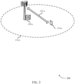
- FIG. 2 illustrates an example of a wireless communications system 200 that supports random access timeline and timing adjustment techniques in accordance with various aspects of the present disclosure.
- wireless communications system 200 may implement aspects of wireless communications system 100.
- Wireless communications system 200 includes a base station 105-a supporting communication with a UE 115-a within coverage area 110-a.
- Base station 105-a and UE 115-a may be examples of the corresponding devices described with reference to FIG. 1 .
- base station 105-a and UE 115-a may exchange messages (e.g., data, control, RACH messages) over communication link 125-a.
- Base station 105-a may perform a downlink transmission that prompts an uplink transmission by UE 115-a in response to the downlink message.
- UE 115-a may wait a minimum time gap before performing the uplink transmission in response to the downlink transmission, which may allow UE 115-a to process the downlink transmission and generate the uplink transmission.
- the duration of the minimum time gap may depend on a downlink decoding time (N1), an uplink transmission preparation time (N2), or a higher layer processing time (L2), each of which may depend on a data numerology.
- wireless communications system 200 may be an NR system that supports multiple numerologies for wireless communication.
- a numerology associated with a higher SCS e.g., 30 kHz, 60 kHz, 120 kHz, 240 kHz, or 480 kHz
- the minimum time gap may utilize a higher number of slots during various portions of the RACH procedure when compared to a numerology associated with a lower tone spacing (e.g., 7.5 kHz, 15 kHz).
- the numerology for a given downlink decoding time N1 or uplink transmission preparation time N2 may be selected by base station 105-a and the numerology may be the same for all UEs 115 (e.g., UE 115-a) attempting to perform an uplink transmission to base station 105-a in response to a downlink transmission by base station 105-a.
- the numerology for a downlink decoding time N1 or an uplink transmission preparation time N2 may be UE-specific.
- the numerology for an uplink transmission preparation time at UE 115-a may be selected based on capabilities of the UE 115-a or channel conditions.
- the numerology for a given downlink decoding time N1 or uplink transmission preparation time N2 may be determined by UE 115-a.
- aspects of the minimum time gap may be determined in accordance with a required timing of base station 105-a, UE 115-a, or both.
- the minimum time gap, N1, N2, and L2 may be expressed in terms of absolute time without correlation to the numerology selected by base station 105-a.
- the minimum time gap, N1, N2, or L2 may be indicated to the UE 115-a (e.g., from base station 105-a) via a random access response message (e.g., a random access response (RAR) grant transmitted via PDCCH, a RAR payload transmitted via a physical downlink shared channel (PDSCH)) or via control or system information (e.g., PDCCH signaling, master information block (MIB) within physical broadcast channel (PBCH), minimum system information block (MSIB), remaining system information (RMSI), or one or more system information blocks (SIBs)).
- RAR random access response
- PDSCH physical downlink shared channel
- control or system information e.g., PDCCH signaling, master information block (MIB) within physical broadcast channel (PBCH), minimum system information block (MSIB), remaining system information (RMSI), or one or more system information blocks (SIBs)
- MIB master information block
- MSIB minimum system information block
- RMSIB remaining system
- base station 105-a and UE 115-a may determine values associated with the minimum time gap a priori in accordance with protocols of wireless communications system 200 (e.g., Standards protocols). In yet other examples, UE 115-a may determine the minimum time gap based on N1, N2, and L2.
- the minimum time gap is determined based on N1, N2, and L2.
- the minimum time gap may be the duration of N1 only, the duration of N2 only, the duration of N1 + N2, the duration of N1 + N2 + L2, or the maximum value (e.g., in absolute time) of N1 and N2
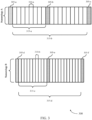
- FIG. 3 illustrates an example of a transmission timing 300 that supports random access timeline and timing adjustment techniques in accordance with various aspects of the present disclosure.
- transmission timing 300 may implement aspects of wireless communications system 100 and 200 as described with reference to FIGs. 1 and 2 .
- Transmission timing 300 may depend on Numerology A or Numerology B, each shown having multiple symbols 305 associated with a given symbol duration 310.
- An indication of transmission timing 300 may be transmitted by a base station 105 to a UE 115.
- the indication may convey a number of slots or symbols to use in determining the minimum time gap between the base station 105 and the UE 115.
- the UE 115 may determine transmission timing 300 (e.g., based on N1, N2, L2, or any combination thereof).
- a base station 105 may transmit a downlink message via PDCCH which orders a UE 115 to start a RACH procedure (i.e., PDCCH order).
- the UE 115 may wait a minimum time gap 315 before transmitting a RACH message so that the UE 115 is able to process the PDCCH order and generate the RACH message.
- the UE 115 may determine minimum time gap 315 based on downlink decoding time N1, uplink transmission preparation time N2, and higher layer processing time L2, each of which may depend on a data numerology.
- the UE 115 may transmit a RACH message (e.g., Msg1) to the base station 105.
- the RACH message may include a RACH preamble, which may be included in a PRACH signal, and a random access radio network temporary identity (RA-RNTI) associated with the UE 115.
- RA-RNTI random access radio network temporary identity
- a base station 105 may transmit a PDCCH order during symbol 305-a to a UE 115.
- the UE 115 may wait a minimum time gap 315-a before transmitting a RACH preamble in symbol 305-b.
- the minimum time gap 315-a may be based on N1, N2, and L2, each of which may depend on a numerology.
- N1 may be defined with respect to a first data numerology.
- N1 may be defined based on a numerology associated with PDCCH, a numerology associated with the downlink bandwidth part where PDCCH is received, any numerology configured by a higher layer solely to determine the minimum time gap, or any default numerology (e.g., a numerology associated with a 15 kHz SCS).
- N1 may be associated with Numerology A of transmission timing 300, where the length of N1 may be based on Tables 1 and 2 below, where Tables 1 and 2 correspond to a first and a second processing capability of a UE 115, respectively: Table 1 ⁇ DL N1 [symbols] No Additional DM-RS Configured Additional DM-RS Configured 0 8 13 1 10 13 2 17 20 3 20 24 Table 2 ⁇ DL N1 [symbols] No Additional DM-RS Configured Additional DM-RS Configured 0 [2.5 - 4] [12] 1 [2.5 - 6] [12]
- N2 may be defined with respect to the first numerology. For instance, N2 may be defined based on a numerology associated with a RACH preamble, a numerology associated with the uplink bandwidth part where PRACH is transmitted, any numerology configured by a higher layer solely to determine the minimum time gap, or any default numerology (e.g., a numerology associated with a 15 kHz SCS).
- N2 may be associated with Numerology A of transmission timing 300, where the length of N2 may be based on Tables 3 and 4 below, where Tables 3 and 4 correspond to a first and a second processing capability of a UE 115, respectively: Table 3 ⁇ DL N 2 [symbols] 0 10 1 12 2 23 3 36 Table 4 ⁇ DL N 2 [symbols] 0 [2.5-6] 1 [2.5-6]
- the SCS corresponding to Numerology A may be found by multiplying a base SCS (e.g., 15 kHz) by 2 ⁇ DL .
- the downlink decoding time N1 may be 8 symbols in length, as shown in Table 1, when no additional demodulation reference signal (DMRS) is needed.
- uplink transmission preparation time N2 may be 10 symbols, as shown in Table 3.
- a second numerology e.g., Numerology B
- ⁇ DL 1
- the SCS is 30 kHz (15 kHz ⁇ 2 1
- the UE 115 may have a first processing capability that defines N1 according to Table 1 and N2 according to Table 3.
- the symbol duration 310 associated with the second numerology may be shorter than the symbol duration associated with the first numerology (e.g., symbol duration 310-a), thus resulting in the UE 115 requiring more symbols 305 to decode a downlink transmission (e.g., a PDCCH order) and prepare uplink transmission (e.g., a RACH preamble).
- a downlink transmission e.g., a PDCCH order
- uplink transmission e.g., a RACH preamble
- N1 and/or N2 may correspond to a numerology for which N1 and/or N2 are not defined (e.g., a numerology associated with a 1.25 kHz SCS or a 5 kHz SCS).
- N1 or N2 may be defined according to a default numerology (e.g., a numerology associated with a 15 kHz SCS).
- the default numerology may be band specific.
- the default numerology may be a numerology associated with a 15 kHz SCS when the UE 115 operates in a sub-6 GHz frequency spectrum band
- the default numerology may be a numerology associated with a 60 kHz SCS when the UE 115 operates in an over-6 GHz frequency spectrum band.
- L2 may be defined according to the processing latency associated with decoding higher layer signaling (e.g., MAC layer). In other examples, L2 may have a fixed duration in absolute time (e.g., 0.5 ms) such that L2 has the same duration for all numerologies.
- higher layer signaling e.g., MAC layer
- L2 may have a fixed duration in absolute time (e.g., 0.5 ms) such that L2 has the same duration for all numerologies.
- the UE 115 may determine a minimum time gap 315 based on N1, N2, and L2.
- a minimum time gap 315 may be the same duration as N1 only.
- N1 may be associated with Numerology A such that N1 is 8 symbols long.
- the resulting a minimum time gap 315-a may separate a PDCCH order received in symbol 305-a with a RACH preamble transmitted in symbol 305-b by 8 symbols.
- a minimum time gap may be the same duration as N1 + N2, for example.
- N1 and N2 may be associated with Numerology A such that N1 is 8 symbols in length and N2 is 10 symbols in length.
- the resulting minimum time gap 315-b may separate a PDCCH order received in symbol 305-a with a RACH preamble transmitted in symbol 305-c by 18 symbols.
- N1 may be associated with Numerology B such that N1 is 10 symbols long.
- the resulting minimum time gap 315-c may separate a PDCCH order received in symbol 305-d with a RACH preamble transmitted in symbol 305-e by 10 symbols.
- a minimum time gap may be the same duration as N1 + N2, for example.
- N1 and N2 may be associated with Numerology B such that N1 is 10 symbols in length and N2 is 12 symbols in length.
- the resulting minimum time gap 315-d may separate a PDCCH order received in symbol 305-d with a RACH preamble transmitted in symbol 305-f by 22 symbols.
- the minimum time gap 315 may be defined as the maximum (or minimum) time duration of N1 and N2.
- N1 and N2 may correspond to the same numerology (e.g., Numerology A). As described above, N1 may have a length of 8 symbols, and N2 may have a length of 10 symbols when N1 and N2 correspond to Numerology A. Because N1 and N2 both correspond to Numerology A, each symbol 305 of N1 and N2 will have the same symbol duration 310-a. In such a case, because N2 has more symbols than N1, and thus a longer duration in time, a minimum time gap 315 may be defined as the same length as N2 (e.g., 10 symbols), thus separating a PDCCH order and RACH preamble by 10 symbols.
- N1 and N2 may correspond to different numerologies (e.g., Numerology A and Numerology B). In such a case, N1 and N2 may be defined based on the numerology corresponding to the lowest SCS (and, thus, the longest symbol duration 310). As described above, N1 may correspond to a first numerology (e.g., Numerology A) and N2 may correspond to a second numerology (e.g., Numerology B), where the second numerology corresponds to a higher SCS than the first numerology. In such a case, a UE 115 may determine to define N1 and N2 based on the first numerology, which may maximize the time duration of N1 and N2.
- numerologies e.g., Numerology A and Numerology B
- the UE 115 may utilize a minimum time gap 315, which is based on N1 and N2, that will have a long enough duration to account for processing delays and transmission preparation times. Further, each of N1 and N2 may be defined based on different numerologies. In such a case, a UE 115 may decide to define N1 and N2 based on the numerology corresponding to the lowest SCS, thus ensuring that N1 and N2 may be long enough in duration to account for processing delays and transmission preparation time.
- the minimum time gap may be determined based on a first SCS associated with a first numerology (e.g., Numerology A) and the RACH preamble may be transmitted with a second SCS associated with a second numerology (e.g., Numerology B).
- a first numerology e.g., Numerology A
- a second numerology e.g., Numerology B
- a base station 105 may send a downlink transmission that contains a TA command to a UE 115, where the TA command may adjust the uplink transmission timing at the UE 115 to align with the transmission timing at the base station 105.
- the TA command may be conveyed in a MAC-CE, which may be included in PDSCH.
- the UE 115 may wait a minimum time gap 315 before applying the TA command to uplink transmissions.
- the length of the minimum time gap 315 may be based on N1, N2, and L2, each of which may be determined in a similar manner as described above.
- a UE 115 may determine the length of N1 according to Table 1 and length of N2 according to Table 3.
- N1 and N2 when associated with a given numerology (e.g., Numerology A), N1 and N2 may be defined as 8 and 10 symbols in length, respectively.
- a minimum time gap 315 may have the same length as N1 + N2, for example, which may result in a minimum time gap 315 of 18 symbols (e.g., minimum time gap 315-c).
- the UE 115 may apply the TA command to uplink transmissions that are transmitted at or after symbol 305-c, which is 18 symbols (i.e., the duration of the minimum time gap 315-c) after the downlink transmission carrying the TA command is received (e.g., at symbol 305-a). Prior to the end of the minimum time gap, the UE 115 may still send uplink transmissions to the base station 105, but these uplink transmissions may not be adjusted according to the TA command received from the base station 105.
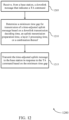
- FIG. 4 illustrates an example of a process flow 400 that supports random access timeline and timing adjustment techniques in accordance with various aspects of the present disclosure.
- process flow 400 may implement aspects of wireless communications systems 100 and 200 with reference to FIGs. 1 and 2 .
- base station 105-b may transmit, to UE 115-b, a control channel message including an indication to perform a random access procedure.
- the control channel message may include a PDCCH order.
- UE 115-b may receive the control channel message according to a first numerology corresponding to a first SCS that is different from a second SCS associated with a second numerology.
- the second numerology may be configured by a higher layer.
- the second numerology is a default numerology.
- the default numerology may be associated with an SCS of 15 kHz.
- the default numerology may be band specific.
- UE 115-b may determine a minimum time gap for transmission of a random access preamble based at least in part on a downlink transmission decoding time, an uplink transmission preparation time, a layer 2 processing time, or a combination thereof. UE 115-b may determine the minimum time gap based solely on the uplink transmission preparation time.
- UE 115-b may calculate the downlink transmission decoding time based at least in part on a numerology associated with the control channel message, a numerology associated with data in a downlink bandwidth part of the control channel message, a numerology for the minimum time gap configured by a higher layer, or a default numerology.
- the default numerology may be associated with an SCS of 15 kHz.
- UE 115-b may calculate the uplink transmission preparation time based at least in part on a numerology associated with the random access preamble, a numerology associated with data in an uplink bandwidth part of a channel used for the random access preamble, a numerology for the minimum time gap configured by a higher layer, or a default numerology.
- the default numerology may be associated with an SCS of 15 kHz.
- the layer 2 processing time may be associated with a MAC latency time.
- UE 115-b may determine that a transmission numerology for the random access preamble is undefined for calculation of the uplink transmission preparation time. In such cases, UE 115-b may select the default numerology for calculating the uplink transmission preparation time based at least in part on determining that the transmission numerology for the random access preamble is undefined. In some cases, the default numerology may be band specific.
- UE 115-b may receive, from base station 105-b, a message indicating a number of symbols corresponding to at least one of the downlink transmission decoding time, the uplink transmission preparation time, the layer 2 processing time, or a combination thereof.
- UE 115-b may identify a first number of symbols based at least in part on a first numerology associated with the downlink transmission decoding time and a second number of symbols based at least in part on a second numerology associated with the uplink transmission preparation time. UE 115-b may determine the minimum time gap based at least in part on a minimum of the first number of symbols and the second number of symbols.
- UE 115-b may determine the minimum time gap based at least in part on the downlink transmission decoding time, the uplink transmission preparation time, a combination of the downlink transmission decoding time and the uplink transmission preparation time, a maximum of the downlink transmission decoding time and the uplink transmission preparation time, a minimum of the downlink transmission decoding time and the uplink transmission preparation time, or the layer 2 processing time.
- UE 115-b may transmit the random access preamble to the base station 105-b in response to the control channel message based at least in part on the minimum time gap. In some examples, UE 115-b may transmit the random access preamble to the base station 105-b after the minimum time gap.
- the minimum time gap, downlink transmission decoding time, uplink transmission preparation time, and layer 2 processing time may be based at least in part on a first numerology.
- the random access preamble may be transmitted with a second numerology different from the first numerology.
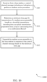
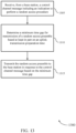
- FIG. 5 illustrates an example of a process flow 500 that supports random access timeline and timing adjustment techniques in accordance with various aspects of the present disclosure.
- process flow 500 may implement aspects of wireless communications systems 100 and 200 with reference to FIGs. 1 and 2 .
- base station 105-c may transmit, to UE 115-c, a downlink message that indicates a TA command.
- the downlink message may include a medium access control MAC-CE that conveys the TA command.
- the downlink message may be transmitted via a PDSCH.
- UE 115-c may determine a minimum time gap for transmission of a time-adjusted uplink message based at least in part on a downlink transmission decoding time, an uplink transmission preparation time, a layer 2 processing time, or a combination thereof. UE 115-c may determine the minimum time gap based at least in part on a summation of the downlink transmission decoding time, the uplink transmission preparation time, and the layer 2 processing time.
- UE 115-c may calculate the downlink transmission decoding time based at least in part on a numerology associated with the downlink message, a numerology associated with data in a downlink bandwidth part of the downlink message, a numerology for the minimum time gap configured by a higher layer, or a default numerology.
- the default numerology may be associated with an SCS of 15 kHz.
- UE 115-c may calculate the uplink transmission preparation time based at least in part on a numerology associated with the time-adjusted uplink message, a numerology associated with data in an uplink bandwidth part of a channel used for the time-adjusted uplink message, or a numerology for the minimum time gap configured by a higher layer.
- UE 115-c may identify a first number of symbols based at least in part on a first numerology associated with the downlink transmission decoding time and a second number of symbols based at least in part on a second numerology associated with the uplink transmission preparation time. UE 115-c may determine the minimum time gap based at least in part on a minimum of the first number of symbols and the second number of symbols.
- UE 115-c may receive, from base station 105-c, a message indicating a number of symbols corresponding to at least one of the downlink transmission decoding time, the uplink transmission preparation time, the layer 2 processing time, or a combination thereof.
- UE 115-c may determine the minimum time gap based at least in part on the downlink transmission decoding time, the uplink transmission preparation time, a combination of the downlink transmission decoding time and the uplink transmission preparation time, a maximum of the downlink transmission decoding time and the uplink transmission preparation time, a minimum of the downlink transmission decoding time and the uplink transmission preparation time, or the layer 2 processing time.
- UE 115-c may transmit the time-adjusted uplink message to the base station 105-c in response to the TA command based at least in part on the minimum time gap.
- UE 115-c may transmit the time-adjusted uplink message to the base station after the minimum time gap.
- UE 115-c may transmit an uplink message according to a previous time adjustment during the minimum time gap.
- the minimum time gap, downlink transmission decoding time, uplink transmission preparation time, and layer 2 processing time may be based at least in part on a first numerology.
- the time-adjusted transmission may be transmitted with a second numerology different from the first numerology.
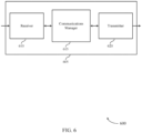
- FIG. 6 shows a block diagram 600 of a device 605 that supports random access timeline and timing adjustment techniques in accordance with aspects of the present disclosure.
- Device 605 may be an example of aspects of a UE 115 as described herein.
- Device 605 may include receiver 610, communications manager 615, and transmitter 620.
- Device 605 may also include a processor. Each of these components may be in communication with one another (e.g., via one or more buses).
- Receiver 610 may receive information such as packets, user data, or control information associated with various information channels (e.g., control channels, data channels, and information related to random access timeline and timing adjustment techniques, etc.). Information may be passed on to other components of the device 605.
- the receiver 610 may be an example of aspects of the transceiver 935 described with reference to FIG. 9 .
- the receiver 610 may utilize a single antenna or a set of antennas.
- Communications manager 615 may be an example of aspects of the communications manager 915 described with reference to FIG. 9 .
- Communications manager 615 and/or at least some of its various sub-components may be implemented in hardware, software executed by a processor, firmware, or any combination thereof. If implemented in software executed by a processor, the functions of the communications manager 615 and/or at least some of its various sub-components may be executed by a general-purpose processor, a digital signal processor (DSP), an application-specific integrated circuit (ASIC), a field-programmable gate array (FPGA) or other programmable logic device, discrete gate or transistor logic, discrete hardware components, or any combination thereof designed to perform the functions described in the present disclosure.
- DSP digital signal processor
- ASIC application-specific integrated circuit
- FPGA field-programmable gate array
- the communications manager 615 and/or at least some of its various sub-components may be physically located at various positions, including being distributed such that portions of functions are implemented at different physical locations by one or more physical devices.
- communications manager 615 and/or at least some of its various sub-components may be a separate and distinct component in accordance with various aspects of the present disclosure.
- communications manager 615 and/or at least some of its various sub-components may be combined with one or more other hardware components, including but not limited to an input/output (I/O) component, a transceiver, a network server, another computing device, one or more other components described in the present disclosure, or a combination thereof in accordance with various aspects of the present disclosure.
- I/O input/output
- Communications manager 615 may receive, from a base station 105, a control channel message including an indication to perform a random access procedure, determine a minimum time gap for transmission of a random access preamble based on a downlink transmission decoding time, an uplink transmission preparation time, a layer 2 processing time, or a combination thereof, and transmit the random access preamble to the base station 105 in response to the control channel message based on the minimum time gap. In some cases, communications manager 615 may determine a minimum time gap for transmission of a random access preamble based on an uplink transmission preparation time.
- the communications manager 615 may also receive, from a base station 105, a control channel message including an indication to perform a random access procedure, determine a minimum time gap for transmission of a random access preamble based on a first numerology, and transmit the random access preamble to the base station 105 in response to the control channel message based on the minimum time gap, where the random access preamble is transmitted with a second numerology different from the first numerology.
- the communications manager 615 may also receive, from a base station 105, a downlink message that indicates a TA command, determine a minimum time gap for transmission of a time-adjusted uplink message based on a downlink transmission decoding time, an uplink transmission preparation time, a layer 2 processing time, or a combination thereof, and transmit the time-adjusted uplink message to the base station 105 in response to the TA command based on the minimum time gap. In some cases, communications manager 615 may determine the minimum time gap for transmission of a time-adjusted uplink message based on a downlink transmission decoding time, an uplink transmission preparation time, or a combination thereof.
- Transmitter 620 may transmit signals generated by other components of the device 605.
- the transmitter 620 may be collocated with a receiver 610 in a transceiver module.
- the transmitter 620 may be an example of aspects of the transceiver 935 described with reference to FIG. 9 .
- the transmitter 620 may utilize a single antenna or a set of antennas.
- FIG. 7 shows a block diagram 700 of a device 705 that supports random access timeline and timing adjustment techniques in accordance with aspects of the present disclosure.
- Device 705 may be an example of aspects of a device 605 or a UE 115 as described with reference to FIG. 6 .
- Device 705 may include receiver 710, communications manager 715, and transmitter 720.
- Device 705 may also include a processor. Each of these components may be in communication with one another (e.g., via one or more buses).
- Receiver 710 may receive information such as packets, user data, or control information associated with various information channels (e.g., control channels, data channels, and information related to random access timeline and timing adjustment techniques, etc.). Information may be passed on to other components of the device 705.
- the receiver 710 may be an example of aspects of the transceiver 935 described with reference to FIG. 9 .
- the receiver 710 may utilize a single antenna or a set of antennas.
- Communications manager 715 may be an example of aspects of the communications manager 915 described with reference to FIG. 9 . Communications manager 715 may also include reception component 725, time gap component 730, and transmission component 735.
- Reception component 725 may receive, from a base station 105, a control channel message including an indication to perform a random access procedure, receive, from the base station 105, a message indicating a number of symbols corresponding to at least one of the downlink transmission decoding time, the uplink transmission preparation time, the layer 2 processing time, or a combination thereof.
- Reception component 725 may receive the control channel message according to the first numerology corresponding to a first SCS that is different from a second SCS associated with the second numerology.
- Reception component 725 may receive, from a base station 105, a downlink message that indicates a TA command, and receive the downlink message via a PDSCH.
- the control channel message includes a PDCCH order.
- the downlink message includes a MAC-CE that conveys the TA command.
- Time gap component 730 may determine a minimum time gap for transmission of a random access preamble based on a downlink transmission decoding time, an uplink transmission preparation time, a layer 2 processing time, or a combination thereof. In some cases, time gap component 730 may determine a minimum time gap for transmission of a random access preamble based on an uplink transmission preparation time. Time gap component 730 may determine the minimum time gap based on a numerology and a number of symbols associated with the random access preamble. Time gap component 730 may determine the minimum time gap based on a minimum of the first number of symbols and the second number of symbols.
- Time gap component 730 may determine the minimum time gap based on the downlink transmission decoding time, the uplink transmission preparation time, a combination of the downlink transmission decoding time and the uplink transmission preparation time, a maximum of the downlink transmission decoding time and the uplink transmission preparation time, a minimum of the downlink transmission decoding time and the uplink transmission preparation time, or the layer 2 processing time.
- Time gap component 730 may determine a minimum time gap for transmission of a random access preamble based on a first numerology, determine a minimum time gap for transmission of a time-adjusted uplink message based on a downlink transmission decoding time, an uplink transmission preparation time, a layer 2 processing time, or a combination thereof and determine the minimum time gap based on a summation of the downlink transmission decoding time, the uplink transmission preparation time, and the layer 2 processing time.
- the layer 2 processing time is associated with a MAC latency time.
- Transmission component 735 may transmit the random access preamble to the base station 105 in response to the control channel message based on the minimum time gap and transmit the random access preamble to the base station 105 after the minimum time gap. Transmission component 735 may transmit the random access preamble to the base station 105 in response to the control channel message based on the minimum time gap, where the random access preamble is transmitted with a second numerology different from the first numerology. Transmission component 735 may transmit the time-adjusted uplink message to the base station 105 in response to the TA command based on the minimum time gap. Transmission component 735 may transmit the time-adjusted uplink message to the base station 105 after the minimum time gap and transmit an uplink message according to a previous time adjustment during the minimum time gap.
- the second numerology is configured by a higher layer. In some examples, the second numerology is a default numerology. In some aspects, the default numerology is associated with an SCS of 15 kHz. In some aspects, the default numerology is band specific.
- FIG. 8 shows a block diagram 800 of a communications manager 815 that supports random access timeline and timing adjustment techniques in accordance with aspects of the present disclosure.
- the communications manager 815 may be an example of aspects of a communications manager 615, a communications manager 715, or a communications manager 915 described with reference to FIGs. 6 , 7 , and 9 .
- the communications manager 815 may include reception component 820, time gap component 825, transmission component 830, calculation component 835, and symbol identifier 840. Each of these modules may communicate, directly or indirectly, with one another (e.g., via one or more buses).
- Reception component 820 may receive, from a base station 105, a control channel message including an indication to perform a random access procedure.
- Reception component 820 may receive, from the base station 105, a message indicating a number of symbols corresponding to at least one of the downlink transmission decoding time, the uplink transmission preparation time, the layer 2 processing time, or a combination thereof.
- Reception component 820 may receive the control channel message according to the first numerology corresponding to a first SCS that is different from a second SCS associated with the second numerology.
- Reception component 820 may receive, from a base station 105, a downlink message that indicates a TA command and receive the downlink message via a PDSCH.
- the control channel message includes a PDCCH order.
- the downlink message includes a MAC-CE that conveys the TA command.
- Time gap component 825 may determine a minimum time gap for transmission of a random access preamble based on a downlink transmission decoding time, an uplink transmission preparation time, a layer 2 processing time, or a combination thereof. In some cases, time gap component 825 may determine a minimum time gap for transmission of a random access preamble based on an uplink transmission preparation time. Time gap component 825 may determine the minimum time gap based on a numerology and a number of symbols associated with the random access preamble.
- Time gap component 825 may determine the minimum time gap based on a minimum of the first number of symbols and the second number of symbols and determine the minimum time gap based on the downlink transmission decoding time, the uplink transmission preparation time, a combination of the downlink transmission decoding time and the uplink transmission preparation time, a maximum of the downlink transmission decoding time and the uplink transmission preparation time, a minimum of the downlink transmission decoding time and the uplink transmission preparation time, or the layer 2 processing time.
- Time gap component 825 may determine a minimum time gap for transmission of a random access preamble based on a first numerology. Time gap component 825 may determine a minimum time gap for transmission of a time-adjusted uplink message based on a downlink transmission decoding time, an uplink transmission preparation time, a layer 2 processing time, or a combination thereof, and determine the minimum time gap based on a summation of the downlink transmission decoding time, the uplink transmission preparation time, and the layer 2 processing time. In some cases, the layer 2 processing time is associated with a MAC latency time.
- Transmission component 830 may transmit the random access preamble to the base station 105 in response to the control channel message based on the minimum time gap. Transmission component 830 may transmit the random access preamble to the base station 105 after the minimum time gap. Transmission component 830 may transmit the random access preamble to the base station 105 in response to the control channel message based on the minimum time gap, where the random access preamble is transmitted with a second numerology different from the first numerology.
- Transmission component 830 may transmit the time-adjusted uplink message to the base station 105 in response to the TA command based on the minimum time gap. Transmission component 830 may transmit the time-adjusted uplink message to the base station 105 after the minimum time gap and transmit an uplink message according to a previous time adjustment during the minimum time gap.
- the second numerology is configured by a higher layer. In some examples, the second numerology is a default numerology. In some aspects, the default numerology is associated with an SCS of 15 kHz. In some aspects, the default numerology is band specific.
- Calculation component 835 may calculate the downlink transmission decoding time based on a numerology associated with the control channel message, a numerology associated with data in a downlink bandwidth part of the control channel message, a numerology for the minimum time gap configured by a higher layer, or a default numerology.
- the default numerology is band specific.
- Calculation component 835 may calculate the uplink transmission preparation time based on a numerology associated with the random access preamble, a numerology associated with data in an uplink bandwidth part of a channel used for the random access preamble, a numerology for the minimum time gap configured by a higher layer, or a default numerology. Calculation component 835 may determine that a transmission numerology for the random access preamble is undefined for calculation of the uplink transmission preparation time and select the default numerology for calculating the uplink transmission preparation time based on determining that the transmission numerology for the random access preamble is undefined.
- Calculation component 835 may calculate the uplink transmission preparation time based on a numerology associated with the time-adjusted uplink message, a numerology associated with data in an uplink bandwidth part of a channel used for the time-adjusted uplink message, or a numerology for the minimum time gap configured by a higher layer. Calculation component 835 may determine that a transmission numerology for the time-adjusted uplink message is undefined for calculation of the uplink transmission preparation time and calculate the downlink transmission decoding time based on a numerology associated with the downlink message, a numerology associated with data in a downlink bandwidth part of the downlink message, or a numerology for the minimum time gap configured by a higher layer.
- Symbol identifier 840 may identify a first number of symbols based on a first numerology associated with the downlink transmission decoding time and identify a second number of symbols based on a second numerology associated with the uplink transmission preparation time. Symbol identifier 840 may identify a first time duration based at least in part on a first numerology associated with the downlink transmission decoding time and identify a second time duration based at least in part on a second numerology associated with the uplink transmission preparation time.
- Time gap component 825 may determine the minimum time gap based at least in part on a maximum of the first time duration and the second time duration.
- Processor 920 may include an intelligent hardware device, (e.g., a general-purpose processor, a DSP, a central processing unit (CPU), a microcontroller, an ASIC, an FPGA or other programmable logic device, a discrete gate or transistor logic component, a discrete hardware component, or any combination thereof).
- processor 920 may be configured to operate a memory array using a memory controller.
- a memory controller may be integrated into processor 920.
- Processor 920 may be configured to execute computer-readable instructions stored in a memory to perform various functions (e.g., functions or tasks supporting random access timeline and timing adjustment techniques).
- Memory 925 may include random access memory (RAM) and read only memory (ROM).
- the memory 925 may store computer-readable, computer-executable software 930 including instructions that, when executed, cause the processor to perform various functions described herein.
- the memory 925 may contain, among other things, a basic I/O system (BIOS) which may control basic hardware or software operation such as the interaction with peripheral components or devices.
- BIOS basic I/O system
- Software 930 may include code to implement aspects of the present disclosure, including code to support random access timeline and timing adjustment techniques.
- Software 930 may be stored in a non-transitory computer-readable medium such as system memory or other memory. In some cases, the software 930 may not be directly executable by the processor but may cause a computer (e.g., when compiled and executed) to perform functions described herein.
- Transceiver 935 may communicate bi-directionally, via one or more antennas, wired, or wireless links as described above.
- the transceiver 935 may represent a wireless transceiver and may communicate bi-directionally with another wireless transceiver.
- the transceiver 935 may also include a modem to modulate the packets and provide the modulated packets to the antennas for transmission, and to demodulate packets received from the antennas.
- the device 905 may include a single antenna 940, or the device 905 may have more than one antenna 940, which may be capable of concurrently transmitting or receiving multiple wireless transmissions.
- I/O controller 945 may manage input and output signals for device 905. I/O controller 945 may also manage peripherals not integrated into device 905. In some cases, I/O controller 945 may represent a physical connection or port to an external peripheral. In some cases, I/O controller 945 may utilize an operating system such as iOS ® , ANDROID ® , MS-DOS ® , MS-WINDOWS ® , OS/2 ® , UNIX ® , LINUX ® , or another known operating system. In other cases, I/O controller 945 may represent or interact with a modem, a keyboard, a mouse, a touchscreen, or a similar device. In some cases, I/O controller 945 may be implemented as part of a processor. In some cases, a user may interact with device 905 via I/O controller 945 or via hardware components controlled by I/O controller 945.
- FIG. 10 shows a flowchart illustrating a method 1000 for random access timeline and timing adjustment techniques in accordance with aspects of the present disclosure.
- the operations of method 1000 may be implemented by a UE 115 or its components as described herein.
- the operations of method 1000 may be performed by a communications manager as described with reference to FIGs. 6 through 9 .
- a UE 115 may execute a set of codes to control the functional elements of the device to perform the functions described below. Additionally or alternatively, the UE 115 may perform aspects of the functions described below using special-purpose hardware.
- the UE 115 may receive, from a base station 105, a control channel message including an indication to perform a random access procedure.
- the operations of 1005 may be performed according to the methods described herein. In certain examples, aspects of the operations of 1005 may be performed by a reception component as described with reference to FIGs. 6 through 9 .
- the UE 115 may determine a minimum time gap for transmission of a random access preamble based at least in part on a downlink transmission decoding time, an uplink transmission preparation time, a layer 2 processing time, or a combination thereof.
- the operations of 1010 may be performed according to the methods described herein. In certain examples, aspects of the operations of 1010 may be performed by a time gap component as described with reference to FIGs. 6 through 9 .
- the UE 115 may transmit the random access preamble to the base station 105 in response to the control channel message based at least in part on the minimum time gap.
- the operations of 1015 may be performed according to the methods described herein. In certain examples, aspects of the operations of 1015 may be performed by a transmission component as described with reference to FIGs. 6 through 9 .
- FIG. 11 shows a flowchart illustrating a method 1100 for random access timeline and timing adjustment techniques in accordance with aspects of the present disclosure.
- the operations of method 1100 may be implemented by a UE 115 or its components as described herein.
- the operations of method 1100 may be performed by a communications manager as described with reference to FIGs. 6 through 9 .
- a UE 115 may execute a set of codes to control the functional elements of the device to perform the functions described below. Additionally or alternatively, the UE 115 may perform aspects of the functions described below using special-purpose hardware.
- the UE 115 may receive, from a base station 105, a control channel message including an indication to perform a random access procedure.
- the operations of 1105 may be performed according to the methods described herein. In certain examples, aspects of the operations of 1105 may be performed by a reception component as described with reference to FIGs. 6 through 9 .
- the UE 115 may determine a minimum time gap for transmission of a random access preamble based at least in part on a first numerology.
- the operations of 1110 may be performed according to the methods described herein. In certain examples, aspects of the operations of 1110 may be performed by a time gap component as described with reference to FIGs. 6 through 9 .
- the UE 115 may transmit the random access preamble to the base station in response to the control channel message based at least in part on the minimum time gap, where the random access preamble is transmitted with a second numerology different from the first numerology.
- the operations of 1115 may be performed according to the methods described herein. In certain examples, aspects of the operations of 1115 may be performed by a transmission component as described with reference to FIGs. 6 through 9 .
- FIG. 12 shows a flowchart illustrating a method 1200 for random access timeline and timing adjustment techniques in accordance with aspects of the present disclosure.
- the operations of method 1200 may be implemented by a UE 115 or its components as described herein.
- the operations of method 1200 may be performed by a communications manager as described with reference to FIGs. 6 through 9 .
- a UE 115 may execute a set of codes to control the functional elements of the device to perform the functions described below. Additionally or alternatively, the UE 115 may perform aspects of the functions described below using special-purpose hardware.
- the UE 115 may receive, from a base station 105, a downlink message that indicates a TA command.
- the operations of 1205 may be performed according to the methods described herein. In certain examples, aspects of the operations of 1205 may be performed by a reception component as described with reference to FIGs. 6 through 9 .
- the UE 115 may determine a minimum time gap for transmission of a time-adjusted uplink message based at least in part on a downlink transmission decoding time, an uplink transmission preparation time, a layer 2 processing time, or a combination thereof.
- the operations of 1210 may be performed according to the methods described herein. In certain examples, aspects of the operations of 1210 may be performed by a time gap component as described with reference to FIGs. 6 through 9 .
- the UE 115 may transmit the time-adjusted uplink message to the base station 105 in response to the TA command based at least in part on the minimum time gap.
- the operations of 1215 may be performed according to the methods described herein. In certain examples, aspects of the operations of 1215 may be performed by a transmission component as described with reference to FIGs. 6 through 9 .
- FIG. 13 shows a flowchart illustrating a method 1300 for random access timeline and timing adjustment techniques in accordance with aspects of the present disclosure.
- the operations of method 1300 may be implemented by a UE 115 or its components as described herein.
- the operations of method 1300 may be performed by a communications manager as described with reference to FIGs. 6 through 9 .
- a UE 115 may execute a set of codes to control the functional elements of the device to perform the functions described below. Additionally or alternatively, the UE 115 may perform aspects of the functions described below using special-purpose hardware.
- the UE 115 may receive, from a base station 105, a control channel message including an indication to perform a random access procedure.
- the operations of 1005 may be performed according to the methods described herein. In certain examples, aspects of the operations of 1005 may be performed by a reception component as described with reference to FIGs. 6 through 9 .
- the UE 115 may determine a minimum time gap for transmission of a random access preamble based at least in part on an uplink transmission preparation time.
- the operations of 1010 may be performed according to the methods described herein. In certain examples, aspects of the operations of 1010 may be performed by a time gap component as described with reference to FIGs. 6 through 9 .
- the UE 115 may transmit the random access preamble to the base station 105 in response to the control channel message based at least in part on the minimum time gap.
- the operations of 1015 may be performed according to the methods described herein. In certain examples, aspects of the operations of 1015 may be performed by a transmission component as described with reference to FIGs. 6 through 9 .
- FIG. 14 shows a flowchart illustrating a method 1200 for random access timeline and timing adjustment techniques in accordance with aspects of the present disclosure.
- the operations of method 1200 may be implemented by a UE 115 or its components as described herein.
- the operations of method 1200 may be performed by a communications manager as described with reference to FIGs. 6 through 9 .
- a UE 115 may execute a set of codes to control the functional elements of the device to perform the functions described below. Additionally or alternatively, the UE 115 may perform aspects of the functions described below using special-purpose hardware.
- the UE 115 may receive, from a base station 105, a downlink message that indicates a TA command.
- the operations of 1205 may be performed according to the methods described herein. In certain examples, aspects of the operations of 1205 may be performed by a reception component as described with reference to FIGs. 6 through 9 .
- the UE 115 may determine a minimum time gap for transmission of a time-adjusted uplink message based at least in part on a downlink transmission decoding time, an uplink transmission preparation time, or a combination thereof.
- the operations of 1210 may be performed according to the methods described herein. In certain examples, aspects of the operations of 1210 may be performed by a time gap component as described with reference to FIGs. 6 through 9 .
- the UE 115 may transmit the time-adjusted uplink message to the base station 105 in response to the TA command based at least in part on the minimum time gap.
- the operations of 1215 may be performed according to the methods described herein. In certain examples, aspects of the operations of 1215 may be performed by a transmission component as described with reference to FIGs. 6 through 9 .
- CDMA code division multiple access
- TDMA time division multiple access
- FDMA frequency division multiple access
- OFDMA orthogonal frequency division multiple access
- SC-FDMA single carrier frequency division multiple access
- a CDMA system may implement a radio technology such as CDMA2000, Universal Terrestrial Radio Access (UTRA), etc.
- CDMA2000 covers IS-2000, IS-95, and IS-856 standards.
- IS-2000 Releases may be commonly referred to as CDMA2000 1X, 1X, etc.
- IS-856 TIA-856) is commonly referred to as CDMA2000 1xEV-DO, High Rate Packet Data (HRPD), etc.
- UTRA includes Wideband CDMA (WCDMA) and other variants of CDMA.
- a TDMA system may implement a radio technology such as Global System for Mobile Communications (GSM).
- GSM Global System for Mobile Communications
- An OFDMA system may implement a radio technology such as Ultra Mobile Broadband (UMB), Evolved UTRA (E-UTRA), Institute of Electrical and Electronics Engineers (IEEE) 802.11 (Wi-Fi), IEEE 802.16 (WiMAX), IEEE 802.20, Flash-OFDM, etc.
- UMB Ultra Mobile Broadband
- E-UTRA Evolved UTRA
- IEEE Institute of Electrical and Electronics Engineers
- Wi-Fi Wi-Fi
- WiMAX IEEE 802.16
- IEEE 802.20 Flash-OFDM
- UTRA and E-UTRA are part of Universal Mobile Telecommunications System (UMTS).
- LTE, LTE-A, and LTE-A Pro are releases of UMTS that use E-UTRA.
- UTRA, E-UTRA, UMTS, LTE, LTE-A, LTE-A Pro, NR, and GSM are described in documents from the organization named "3rd Generation Partnership Project" (3GPP).
- CDMA2000 and UMB are described in documents from an organization named "3rd Generation Partnership Project 2" (3GPP2).
- 3GPP2 3rd Generation Partnership Project 2
- the techniques described herein may be used for the systems and radio technologies mentioned above as well as other systems and radio technologies. While aspects of an LTE, LTE-A, LTE-A Pro, or NR system may be described for purposes of example, and LTE, LTE-A, LTE-A Pro, or NR terminology may be used in much of the description, the techniques described herein are applicable beyond LTE, LTE-A, LTE-A Pro, or NR applications.
- a macro cell generally covers a relatively large geographic area (e.g., several kilometers in radius) and may allow unrestricted access by UEs 115 with service subscriptions with the network provider.
- a small cell may be associated with a lower-powered base station 105, as compared with a macro cell, and a small cell may operate in the same or different (licensed, unlicensed, etc.) frequency bands as macro cells.
- Small cells may include pico cells, femto cells, and micro cells according to various examples.
- a pico cell for example, may cover a small geographic area and may allow unrestricted access by UEs 115 with service subscriptions with the network provider.
- a femto cell may also cover a small geographic area (e.g., a home) and may provide restricted access by UEs 115 having an association with the femto cell (e.g., UEs 115 in a closed subscriber group (CSG), UEs 115 for users in the home, and the like).
- An eNB for a macro cell may be referred to as a macro eNB.
- An eNB for a small cell may be referred to as a small cell eNB, a pico eNB, a femto eNB, or a home eNB.
- An eNB may support one or multiple (e.g., two, three, four, and the like) cells, and may also support communications using one or multiple CCs.
- the wireless communications system 100 or systems described herein may support synchronous or asynchronous operation.
- the base stations 105 may have similar frame timing, and transmissions from different base stations 105 may be approximately aligned in time.
- the base stations 105 may have different frame timing, and transmissions from different base stations 105 may not be aligned in time.
- the techniques described herein may be used for either synchronous or asynchronous operations.
- Information and signals described herein may be represented using any of a variety of different technologies and techniques.
- data, instructions, commands, information, signals, bits, symbols, and chips that may be referenced throughout the above description may be represented by voltages, currents, electromagnetic waves, magnetic fields or particles, optical fields or particles, or any combination thereof.
- a general-purpose processor may be a microprocessor, but in the alternative, the processor may be any conventional processor, controller, microcontroller, or state machine.
- a processor may also be implemented as a combination of computing devices (e.g., a combination of a DSP and a microprocessor, multiple microprocessors, one or more microprocessors in conjunction with a DSP core, or any other such configuration).
- the functions described herein may be implemented in hardware, software executed by a processor, firmware, or any combination thereof. If implemented in software executed by a processor, the functions may be stored on or transmitted over as one or more instructions or code on a computer-readable medium. Other examples and implementations are within the scope of the disclosure and appended claims. For example, due to the nature of software, functions described above can be implemented using software executed by a processor, hardware, firmware, hardwiring, or combinations of any of these. Features implementing functions may also be physically located at various positions, including being distributed such that portions of functions are implemented at different physical locations.
- Computer-readable media includes both non-transitory computer storage media and communication media including any medium that facilitates transfer of a computer program from one place to another.
- a non-transitory storage medium may be any available medium that can be accessed by a general purpose or special purpose computer.
- non-transitory computer-readable media may include RAM, ROM, electrically erasable programmable ROM (EEPROM), flash memory, compact disk (CD) ROM or other optical disk storage, magnetic disk storage or other magnetic storage devices, or any other non-transitory medium that can be used to carry or store desired program code means in the form of instructions or data structures and that can be accessed by a general-purpose or special-purpose computer, or a general-purpose or special-purpose processor.
- any connection is properly termed a computer-readable medium.
- the software is transmitted from a website, server, or other remote source using a coaxial cable, fiber optic cable, twisted pair, digital subscriber line (DSL), or wireless technologies such as infrared, radio, and microwave
- the coaxial cable, fiber optic cable, twisted pair, DSL, or wireless technologies such as infrared, radio, and microwave are included in the definition of medium.
- Disk and disc include CD, laser disc, optical disc, digital versatile disc (DVD), floppy disk and Blu-ray disc where disks usually reproduce data magnetically, while discs reproduce data optically with lasers. Combinations of the above are also included within the scope of computer-readable media.
Landscapes
- Engineering & Computer Science (AREA)
- Signal Processing (AREA)
- Computer Networks & Wireless Communication (AREA)
- Mobile Radio Communication Systems (AREA)
Claims (14)
- Verfahren (1300) für drahtlose Kommunikation, umfassend:Empfangen (1305) einer Steuerkanalnachricht von einer Basisstation, die eine Anzeige zur Durchführung eines Zufallszugriffsverfahrens umfasst;Bestimmen (1310) einer minimalen Zeitlücke für die Übertragung einer Zufallszugriffspräambel zumindest teilweise auf der Grundlage einer Vorbereitungszeit für die Übertragung in der Aufwärtsrichtung, wobei die Vorbereitungszeit für die Übertragung in der Aufwärtsrichtung eine Verzögerung ist, die sich auf die Vorbereitung der Übertragung in der Aufwärtsrichtung für die Übertragung zur Basisstation bezieht;Berechnen der Aufwärtsstrecken-Übertragungsvorbereitungszeit zumindest teilweise auf der Grundlage einer Numerologie, die mit der Zufallszugriffs-Präambel assoziiert ist, einer Numerologie, die mit Daten in einem Aufwärtsstrecken-Bandbreitenteil eines für die Zufallszugriffs-Präambel verwendeten Kanals assoziiert ist, einer Numerologie für die von einer höheren Schicht konfigurierte minimale Zeitlücke oder einer Standard-Numerologie, wobei die Standard-Numerologie mit einem Unterträgerabstand von 15 Kilohertz, kHz, assoziiert ist und bandspezifisch ist; undÜbertragen (1315) der Zufallszugriffs-Präambel an die Basisstation als Antwort auf die Steuerkanalnachricht, die zumindest teilweise auf dem minimalen Zeitabstand basiert.
- Verfahren nach Anspruch 1, ferner umfassend:
Bestimmen der minimalen Zeitlücke allein auf der Grundlage der Vorbereitungszeit für die Übertragung in der Aufwärtsrichtung. - Verfahren nach Anspruch 1, ferner umfassend:Bestimmen der minimalen Zeitlücke zumindest teilweise auf der Grundlage einer Abwärtsstrecken-Übertragungsdekodierzeit, einer Schicht-2-Verarbeitungszeit oder einer Kombination davon; undBerechnen der Abwärtsstrecken-Übertragungsdekodierzeit zumindest teilweise auf der Grundlage einer Numerologie, die der Steuerkanalnachricht zugeordnet ist, einer Numerologie, die Daten in einem Abwärtsstrecken-Bandbreitenteil der Steuerkanalnachricht zugeordnet ist, einer Numerologie für die minimale Zeitlücke, die von einer höheren Schicht konfiguriert wird, oder einer Standard-Numerologie.
- Verfahren nach Anspruch 1, ferner umfassend:Bestimmen, dass eine Übertragungsnumerologie für die Präambel mit wahlfreiem Zugriff für die Berechnung der Vorbereitungszeit für die Übertragung in der Aufwärtsrichtung undefiniert ist; undAuswählen der Standardnumerologie zum Berechnen der Aufwärtsübertragungsvorbereitungszeit zumindest teilweise auf der Grundlage der Feststellung, dass die Übertragungsnumerologie für die Zufallszugriffspräambel undefiniert ist.
- Verfahren nach Anspruch 3, ferner umfassend:Identifizieren einer ersten Zeitdauer, die zumindest teilweise auf einer ersten Numerologie basiert, die mit der Dekodierzeit der Abwärtsstrecken-Übertragung verbunden ist;Identifizieren einer zweiten Zeitdauer, die zumindest teilweise auf einer zweiten Numerologie basiert, die mit der Vorbereitungszeit für die Aufwärtsstrecken-Übertragung verbunden ist; undBestimmen der minimalen Zeitlücke zumindest teilweise auf der Grundlage eines Maximums aus der ersten Zeitdauer und der zweiten Zeitdauer.
- Verfahren nach Anspruch 3, ferner umfassend:Identifizieren einer ersten Anzahl von Symbolen zumindest teilweise auf der Grundlage einer ersten Numerologie, die mit der Dekodierzeit der Abwärtsstrecken-Übertragung verbunden ist;Identifizieren einer zweiten Anzahl von Symbolen zumindest teilweise auf der Grundlage einer zweiten Numerologie, die mit der Vorbereitungszeit der Aufwärtsübertragung verbunden ist; undBestimmen der minimalen Zeitlücke zumindest teilweise auf der Grundlage eines Minimums aus der ersten Anzahl von Symbolen und der zweiten Anzahl von Symbolen.
- Verfahren nach Anspruch 3, ferner umfassend:
Bestimmen der minimalen Zeitlücke zumindest teilweise auf der Grundlage der Dekodierzeit für die Abwärtsstrecken-Übertragung, der Vorbereitungszeit für die Aufwärtsstrecken-Übertragung, einer Kombination aus der Dekodierzeit für die Abwärtsstrecken-Übertragung und der Vorbereitungszeit für die Aufwärtsstrecken-Übertragung, einem Maximum aus der Dekodierzeit für die Abwärtsstrecken-Übertragung und der Vorbereitungszeit für die Aufwärtsstrecken-Übertragung, einem Minimum aus der Dekodierzeit für die Abwärtsstrecken-Übertragung und der Vorbereitungszeit für die Aufwärtsstrecken-Übertragung oder der Schicht-2-Verarbeitungszeit. - Verfahren nach Anspruch 1, ferner umfassend:
Empfangen einer Nachricht von der Basisstation, die eine Anzahl von Symbolen angibt, die mindestens einer Dekodierzeit für die Abwärtsstrecken-Übertragung, der Vorbereitungszeit für die Aufwärtsstrecken-Übertragung, einer Verarbeitungszeit der Schicht 2 oder einer Kombination davon entspricht. - Verfahren nach Anspruch 1, ferner umfassend:
Übertragen der Zufallszugriffspräambel an die Basisstation nach dem minimalen Zeitabstand. - Verfahren nach Anspruch 3, wobei die Schicht-2-Verarbeitungszeit mit einer Medienzugriffskontrolle-, MAC-, Latenzzeit verbunden ist.
- Verfahren nach Anspruch 1, wobei die Steuerkanalnachricht einen physikalischen Abwärtsstrecken-Kontrollkanalbefehl, PDCCH, umfasst.
- Vorrichtung (700; 705) für drahtlose Kommunikation, aufweisend:Mittel (710; 725) zum Empfangen einer Steuerkanalnachricht von einer Basisstation, die eine Angabe zur Durchführung eines Zufallszugriffsverfahrens enthält;Mittel (730) zum Bestimmen einer minimalen Zeitlücke für die Übertragung einer Zufallszugriffspräambel, die zumindest teilweise auf einer Vorbereitungszeit für die Übertragung in der Aufwärtsrichtung basiert, wobei die Vorbereitungszeit für die Übertragung in der Aufwärtsrichtung eine Verzögerung ist, die sich auf die Vorbereitung der Übertragung in der Aufwärtsrichtung für die Übertragung zur Basisstation bezieht;Mittel zum Berechnen der Vorbereitungszeit für die Aufwärtsstrecken-Übertragung zumindest teilweise auf der Grundlage einer Numerologie, die mit der Zufallszugriffs-Präambel verknüpft ist, einer Numerologie, die mit Daten in einem Aufwärtsstrecken-Bandbreitenteil eines für die Zufallszugriffs-Präambel verwendeten Kanals verknüpft ist, einer Numerologie für die von einer höheren Schicht konfigurierte minimale Zeitlücke oder einer Standard-Numerologie, wobei die Standard-Numerologie mit einem Unterträgerabstand von 15 Kilohertz, kHz, verknüpft und bandspezifisch ist; undMittel (720; 735) zum Übertragen der Zufallszugriffs-Präambel an die Basisstation als Reaktion auf die Steuerkanalnachricht, die zumindest teilweise auf der minimalen Zeitlücke basiert.
- Vorrichtung für drahtlose Kommunikation nach Anspruch 12, ferner aufweisend:
Mittel zum Bestimmen der minimalen Zeitlücke allein auf der Grundlage der Vorbereitungszeit für die Übertragung in der Aufwärtsrichtung. - Computerprogramm mit Befehlen, die, wenn sie auf mindestens einem Prozessor ausgeführt werden, den Prozessor veranlassen, das Verfahren nach einem der Ansprüche 1 bis 11 auszuführen.
Applications Claiming Priority (4)
| Application Number | Priority Date | Filing Date | Title |
|---|---|---|---|
| US201862710485P | 2018-02-16 | 2018-02-16 | |
| US16/250,801 US10959268B2 (en) | 2018-02-16 | 2019-01-17 | Random access timeline and timing adjustment techniques |
| EP19704149.4A EP3753172B1 (de) | 2018-02-16 | 2019-01-22 | Techniken zur anpassung von direktzugriffszeitline und -timing |
| PCT/US2019/014486 WO2019160651A1 (en) | 2018-02-16 | 2019-01-22 | Random access timeline and timing adjustment techniques |
Related Parent Applications (2)
| Application Number | Title | Priority Date | Filing Date |
|---|---|---|---|
| EP19704149.4A Division-Into EP3753172B1 (de) | 2018-02-16 | 2019-01-22 | Techniken zur anpassung von direktzugriffszeitline und -timing |
| EP19704149.4A Division EP3753172B1 (de) | 2018-02-16 | 2019-01-22 | Techniken zur anpassung von direktzugriffszeitline und -timing |
Publications (3)
| Publication Number | Publication Date |
|---|---|
| EP3849129A1 EP3849129A1 (de) | 2021-07-14 |
| EP3849129C0 EP3849129C0 (de) | 2023-11-15 |
| EP3849129B1 true EP3849129B1 (de) | 2023-11-15 |
Family
ID=67618355
Family Applications (4)
| Application Number | Title | Priority Date | Filing Date |
|---|---|---|---|
| EP19704149.4A Active EP3753172B1 (de) | 2018-02-16 | 2019-01-22 | Techniken zur anpassung von direktzugriffszeitline und -timing |
| EP22195359.9A Active EP4123951B1 (de) | 2018-02-16 | 2019-01-22 | Techniken zur anpassung von direktzugriffszeitline und -timing |
| EP21159373.6A Active EP3846377B1 (de) | 2018-02-16 | 2019-01-22 | Techniken zur anpassung von direktzugriffszeitline und -timing |
| EP21159358.7A Active EP3849129B1 (de) | 2018-02-16 | 2019-01-22 | Techniken zur anpassung von direktzugriffszeitline und -timing |
Family Applications Before (3)
| Application Number | Title | Priority Date | Filing Date |
|---|---|---|---|
| EP19704149.4A Active EP3753172B1 (de) | 2018-02-16 | 2019-01-22 | Techniken zur anpassung von direktzugriffszeitline und -timing |
| EP22195359.9A Active EP4123951B1 (de) | 2018-02-16 | 2019-01-22 | Techniken zur anpassung von direktzugriffszeitline und -timing |
| EP21159373.6A Active EP3846377B1 (de) | 2018-02-16 | 2019-01-22 | Techniken zur anpassung von direktzugriffszeitline und -timing |
Country Status (4)
| Country | Link |
|---|---|
| US (1) | US10959268B2 (de) |
| EP (4) | EP3753172B1 (de) |
| CN (1) | CN111713066B (de) |
| WO (1) | WO2019160651A1 (de) |
Families Citing this family (8)
| Publication number | Priority date | Publication date | Assignee | Title |
|---|---|---|---|---|
| CN114586461B (zh) | 2019-10-26 | 2025-02-25 | 高通股份有限公司 | 上行链路发送(ul tx)准备时间 |
| EP4104371A1 (de) * | 2020-02-14 | 2022-12-21 | Telefonaktiebolaget Lm Ericsson (Publ) | Verfahren zur unterstützung von schnell schaltbaren uplink-übertragungen über träger |
| US11576213B2 (en) * | 2020-02-24 | 2023-02-07 | Qualcomm Incorporated | Random access channel transmission procedures in higher bands |
| CN113811001B (zh) * | 2020-06-16 | 2024-10-01 | 维沃移动通信有限公司 | 基本时间单元的处理方法、装置及电子设备 |
| US12438678B2 (en) * | 2020-08-05 | 2025-10-07 | Apple Inc. | System and methods for PDCCH monitoring in new radio |
| CN114501668B (zh) * | 2020-10-23 | 2023-11-17 | 展讯半导体(南京)有限公司 | 用于物理随机接入信道的消息传输方法及装置、存储介质、终端、基站 |
| US12396036B2 (en) | 2021-08-05 | 2025-08-19 | Qualcomm Incorporated | PDCCH ordered random access channel procedure for reduced capability user equipment |
| US20230147159A1 (en) * | 2021-11-11 | 2023-05-11 | Qualcomm Incorporated | Time gaps for segment-based uplink transmissions in non-terrestrial networks |
Family Cites Families (17)
| Publication number | Priority date | Publication date | Assignee | Title |
|---|---|---|---|---|
| JP5169442B2 (ja) * | 2008-04-25 | 2013-03-27 | 富士通株式会社 | 無線基地局、移動局および通信方法 |
| EP2445280B1 (de) * | 2008-06-02 | 2014-09-24 | Fujitsu Limited | Zeiteinstellungsverfahren, Benutzerendgerät, Basisstation und mobiles Kommunikationssystem |
| US8494572B2 (en) * | 2008-06-24 | 2013-07-23 | Qualcomm Incorporated | Method and apparatus for power control of first data transmission in random access procedure of FDMA communication system |
| US8842567B2 (en) * | 2010-04-28 | 2014-09-23 | Lg Electronics Inc. | Method and apparatus for performing random access procedures in a wireless communication system |
| KR102073027B1 (ko) * | 2011-04-05 | 2020-02-04 | 삼성전자 주식회사 | 반송파 집적 기술을 사용하는 무선통신시스템에서 복수 개의 타임 정렬 타이머 운용 방법 및 장치 |
| WO2017088898A1 (en) | 2015-11-23 | 2017-06-01 | Nokia Solutions And Networks Oy | User device beamforming training in wireless networks |
| CN108476117B (zh) * | 2016-01-11 | 2021-11-05 | 索尼公司 | 一种发送或接收数据的方法、通信装置、基础设施设备 |
| US11540320B2 (en) * | 2016-01-15 | 2022-12-27 | Ntt Docomo, Inc. | User terminal, radio base station and radio communication method |
| JP2019518392A (ja) | 2016-06-15 | 2019-06-27 | コンヴィーダ ワイヤレス, エルエルシー | 新しい無線のための許可不要アップリンク伝送 |
| AU2017284729B2 (en) | 2016-06-15 | 2020-03-05 | Lg Electronics Inc. | Method and apparatus for transmitting and receiving wireless signal in wireless communication system |
| EP4425856A3 (de) | 2016-07-28 | 2024-11-20 | LG Electronics Inc. | Verfahren zum empfangen eines referenzsignals in einem drahtloskommunikationssystem und vorrichtung dafür |
| US10433343B2 (en) * | 2016-07-28 | 2019-10-01 | Asustek Computer Inc. | Method and apparatus for improving random access procedure in a wireless communication system |
| CN107666722A (zh) * | 2016-07-28 | 2018-02-06 | 华硕电脑股份有限公司 | 改善无线系统的随机接入程序的消息3传送的方法及设备 |
| US10673672B2 (en) * | 2016-09-30 | 2020-06-02 | Motorola Mobility Llc | Method and apparatus for synchronization signals and random access for flexible radio communication |
| US11310756B2 (en) * | 2017-01-09 | 2022-04-19 | Nokia Technologies Oy | Flexible indication of transmission timing |
| EP3582572A4 (de) * | 2017-02-09 | 2020-12-30 | LG Electronics Inc. -1- | Verfahren zum senden und empfangen von uplink-signalen zwischen einem endgerät und einer basisstation in einem drahtloskommunikationssystem und vorrichtung zur unterstützung davon |
| WO2019139442A1 (en) * | 2018-01-12 | 2019-07-18 | Innovative Technology Lab Co., Ltd. | Apparatus and method for performing random access in wireless communication system |
-
2019
- 2019-01-17 US US16/250,801 patent/US10959268B2/en active Active
- 2019-01-22 EP EP19704149.4A patent/EP3753172B1/de active Active
- 2019-01-22 EP EP22195359.9A patent/EP4123951B1/de active Active
- 2019-01-22 EP EP21159373.6A patent/EP3846377B1/de active Active
- 2019-01-22 CN CN201980012925.9A patent/CN111713066B/zh active Active
- 2019-01-22 WO PCT/US2019/014486 patent/WO2019160651A1/en not_active Ceased
- 2019-01-22 EP EP21159358.7A patent/EP3849129B1/de active Active
Also Published As
| Publication number | Publication date |
|---|---|
| EP4123951C0 (de) | 2025-11-05 |
| EP3849129C0 (de) | 2023-11-15 |
| EP3846377A1 (de) | 2021-07-07 |
| EP3753172B1 (de) | 2022-11-02 |
| CN111713066A (zh) | 2020-09-25 |
| US20190261422A1 (en) | 2019-08-22 |
| CN111713066B (zh) | 2023-03-31 |
| WO2019160651A1 (en) | 2019-08-22 |
| EP3849129A1 (de) | 2021-07-14 |
| US10959268B2 (en) | 2021-03-23 |
| EP3753172A1 (de) | 2020-12-23 |
| EP3846377B1 (de) | 2023-03-01 |
| EP4123951B1 (de) | 2025-11-05 |
| EP4123951A1 (de) | 2023-01-25 |
Similar Documents
| Publication | Publication Date | Title |
|---|---|---|
| EP3738387B1 (de) | Bestimmung einer anzahl von rach-präambel-nachrichten zur übertragung | |
| EP3900249B1 (de) | Quasi-kollokationsrücksetzung für ein benutzergerät, das einen einzigen aktiven übertragungskonfigurationsanzeigezustand unterstützt | |
| WO2020102254A1 (en) | Configuring transmission configuration indication states on an initial control resource set | |
| WO2020092197A1 (en) | Multiple msg1 for pdcch ordered rach | |
| EP3849129B1 (de) | Techniken zur anpassung von direktzugriffszeitline und -timing | |
| EP4708760A2 (de) | Präambel für demodulationsreferenzsignalzuordnung für direktzugriffsprozeduren | |
| EP3682585B1 (de) | Techniken zur signalisierung von burst-set-mustern von synchronisationssignalen | |
| EP3850899B1 (de) | Wiederverwendung einer kontrollkanalressource im zusammenhang mit einem erstzugriff | |
| WO2019033876A1 (en) | CONFIGURATIONS FOR TRANSMITTING RANDOM ACCESS PREAMBLE MESSAGES | |
| EP4492881A2 (de) | Annahme einer standard-psy-co-lokalisierung zur auslösung eines trägerübergreifenden referenzsignals | |
| AU2020276531B2 (en) | Two-step random access channel configuration | |
| WO2020102490A1 (en) | Transmission configuration indication state ordering for an initial control resource set | |
| EP4091368B1 (de) | Breitband-steuersignalübertragung | |
| WO2019099271A1 (en) | Demodulation reference signal transmission | |
| EP3909335B1 (de) | Konfiguration von uplink-steuerkanalressourcen für die kommunikation in einem gemeinsam genutzten funkfrequenzspektrum | |
| EP3777432A1 (de) | Signalisierung zur anzeige von standorten eines dedizierten direktzugriffskanalbereichs in einer zeitdomäne | |
| WO2020168113A1 (en) | On demand system information triggering | |
| WO2020171954A1 (en) | Wakeup signaling in an unlicensed radio frequency spectrum band |
Legal Events
| Date | Code | Title | Description |
|---|---|---|---|
| PUAI | Public reference made under article 153(3) epc to a published international application that has entered the european phase |
Free format text: ORIGINAL CODE: 0009012 |
|
| STAA | Information on the status of an ep patent application or granted ep patent |
Free format text: STATUS: REQUEST FOR EXAMINATION WAS MADE |
|
| 17P | Request for examination filed |
Effective date: 20210225 |
|
| AC | Divisional application: reference to earlier application |
Ref document number: 3753172 Country of ref document: EP Kind code of ref document: P |
|
| AK | Designated contracting states |
Kind code of ref document: A1 Designated state(s): AL AT BE BG CH CY CZ DE DK EE ES FI FR GB GR HR HU IE IS IT LI LT LU LV MC MK MT NL NO PL PT RO RS SE SI SK SM TR |
|
| GRAP | Despatch of communication of intention to grant a patent |
Free format text: ORIGINAL CODE: EPIDOSNIGR1 |
|
| STAA | Information on the status of an ep patent application or granted ep patent |
Free format text: STATUS: GRANT OF PATENT IS INTENDED |
|
| INTG | Intention to grant announced |
Effective date: 20230607 |
|
| GRAS | Grant fee paid |
Free format text: ORIGINAL CODE: EPIDOSNIGR3 |
|
| GRAA | (expected) grant |
Free format text: ORIGINAL CODE: 0009210 |
|
| STAA | Information on the status of an ep patent application or granted ep patent |
Free format text: STATUS: THE PATENT HAS BEEN GRANTED |
|
| AC | Divisional application: reference to earlier application |
Ref document number: 3753172 Country of ref document: EP Kind code of ref document: P |
|
| AK | Designated contracting states |
Kind code of ref document: B1 Designated state(s): AL AT BE BG CH CY CZ DE DK EE ES FI FR GB GR HR HU IE IS IT LI LT LU LV MC MK MT NL NO PL PT RO RS SE SI SK SM TR |
|
| REG | Reference to a national code |
Ref country code: CH Ref legal event code: EP Ref country code: GB Ref legal event code: FG4D |
|
| REG | Reference to a national code |
Ref country code: DE Ref legal event code: R096 Ref document number: 602019041735 Country of ref document: DE |
|
| REG | Reference to a national code |
Ref country code: IE Ref legal event code: FG4D |
|
| U01 | Request for unitary effect filed |
Effective date: 20231204 |
|
| U07 | Unitary effect registered |
Designated state(s): AT BE BG DE DK EE FI FR IT LT LU LV MT NL PT SE SI Effective date: 20231208 |
|
| U20 | Renewal fee for the european patent with unitary effect paid |
Year of fee payment: 6 Effective date: 20231219 |
|
| PG25 | Lapsed in a contracting state [announced via postgrant information from national office to epo] |
Ref country code: GR Free format text: LAPSE BECAUSE OF FAILURE TO SUBMIT A TRANSLATION OF THE DESCRIPTION OR TO PAY THE FEE WITHIN THE PRESCRIBED TIME-LIMIT Effective date: 20240216 |
|
| PG25 | Lapsed in a contracting state [announced via postgrant information from national office to epo] |
Ref country code: IS Free format text: LAPSE BECAUSE OF FAILURE TO SUBMIT A TRANSLATION OF THE DESCRIPTION OR TO PAY THE FEE WITHIN THE PRESCRIBED TIME-LIMIT Effective date: 20240315 |
|
| PG25 | Lapsed in a contracting state [announced via postgrant information from national office to epo] |
Ref country code: ES Free format text: LAPSE BECAUSE OF FAILURE TO SUBMIT A TRANSLATION OF THE DESCRIPTION OR TO PAY THE FEE WITHIN THE PRESCRIBED TIME-LIMIT Effective date: 20231115 |
|
| PG25 | Lapsed in a contracting state [announced via postgrant information from national office to epo] |
Ref country code: IS Free format text: LAPSE BECAUSE OF FAILURE TO SUBMIT A TRANSLATION OF THE DESCRIPTION OR TO PAY THE FEE WITHIN THE PRESCRIBED TIME-LIMIT Effective date: 20240315 Ref country code: GR Free format text: LAPSE BECAUSE OF FAILURE TO SUBMIT A TRANSLATION OF THE DESCRIPTION OR TO PAY THE FEE WITHIN THE PRESCRIBED TIME-LIMIT Effective date: 20240216 Ref country code: ES Free format text: LAPSE BECAUSE OF FAILURE TO SUBMIT A TRANSLATION OF THE DESCRIPTION OR TO PAY THE FEE WITHIN THE PRESCRIBED TIME-LIMIT Effective date: 20231115 |
|
| PG25 | Lapsed in a contracting state [announced via postgrant information from national office to epo] |
Ref country code: RS Free format text: LAPSE BECAUSE OF FAILURE TO SUBMIT A TRANSLATION OF THE DESCRIPTION OR TO PAY THE FEE WITHIN THE PRESCRIBED TIME-LIMIT Effective date: 20231115 Ref country code: PL Free format text: LAPSE BECAUSE OF FAILURE TO SUBMIT A TRANSLATION OF THE DESCRIPTION OR TO PAY THE FEE WITHIN THE PRESCRIBED TIME-LIMIT Effective date: 20231115 Ref country code: NO Free format text: LAPSE BECAUSE OF FAILURE TO SUBMIT A TRANSLATION OF THE DESCRIPTION OR TO PAY THE FEE WITHIN THE PRESCRIBED TIME-LIMIT Effective date: 20240215 Ref country code: HR Free format text: LAPSE BECAUSE OF FAILURE TO SUBMIT A TRANSLATION OF THE DESCRIPTION OR TO PAY THE FEE WITHIN THE PRESCRIBED TIME-LIMIT Effective date: 20231115 |
|
| PG25 | Lapsed in a contracting state [announced via postgrant information from national office to epo] |
Ref country code: CZ Free format text: LAPSE BECAUSE OF FAILURE TO SUBMIT A TRANSLATION OF THE DESCRIPTION OR TO PAY THE FEE WITHIN THE PRESCRIBED TIME-LIMIT Effective date: 20231115 |
|
| PG25 | Lapsed in a contracting state [announced via postgrant information from national office to epo] |
Ref country code: SK Free format text: LAPSE BECAUSE OF FAILURE TO SUBMIT A TRANSLATION OF THE DESCRIPTION OR TO PAY THE FEE WITHIN THE PRESCRIBED TIME-LIMIT Effective date: 20231115 |
|
| PG25 | Lapsed in a contracting state [announced via postgrant information from national office to epo] |
Ref country code: SM Free format text: LAPSE BECAUSE OF FAILURE TO SUBMIT A TRANSLATION OF THE DESCRIPTION OR TO PAY THE FEE WITHIN THE PRESCRIBED TIME-LIMIT Effective date: 20231115 Ref country code: SK Free format text: LAPSE BECAUSE OF FAILURE TO SUBMIT A TRANSLATION OF THE DESCRIPTION OR TO PAY THE FEE WITHIN THE PRESCRIBED TIME-LIMIT Effective date: 20231115 Ref country code: RO Free format text: LAPSE BECAUSE OF FAILURE TO SUBMIT A TRANSLATION OF THE DESCRIPTION OR TO PAY THE FEE WITHIN THE PRESCRIBED TIME-LIMIT Effective date: 20231115 Ref country code: CZ Free format text: LAPSE BECAUSE OF FAILURE TO SUBMIT A TRANSLATION OF THE DESCRIPTION OR TO PAY THE FEE WITHIN THE PRESCRIBED TIME-LIMIT Effective date: 20231115 |
|
| REG | Reference to a national code |
Ref country code: DE Ref legal event code: R097 Ref document number: 602019041735 Country of ref document: DE |
|
| PG25 | Lapsed in a contracting state [announced via postgrant information from national office to epo] |
Ref country code: MC Free format text: LAPSE BECAUSE OF FAILURE TO SUBMIT A TRANSLATION OF THE DESCRIPTION OR TO PAY THE FEE WITHIN THE PRESCRIBED TIME-LIMIT Effective date: 20231115 |
|
| PG25 | Lapsed in a contracting state [announced via postgrant information from national office to epo] |
Ref country code: MC Free format text: LAPSE BECAUSE OF FAILURE TO SUBMIT A TRANSLATION OF THE DESCRIPTION OR TO PAY THE FEE WITHIN THE PRESCRIBED TIME-LIMIT Effective date: 20231115 |
|
| REG | Reference to a national code |
Ref country code: CH Ref legal event code: PL |
|
| PLBE | No opposition filed within time limit |
Free format text: ORIGINAL CODE: 0009261 |
|
| STAA | Information on the status of an ep patent application or granted ep patent |
Free format text: STATUS: NO OPPOSITION FILED WITHIN TIME LIMIT |
|
| PG25 | Lapsed in a contracting state [announced via postgrant information from national office to epo] |
Ref country code: CH Free format text: LAPSE BECAUSE OF NON-PAYMENT OF DUE FEES Effective date: 20240131 |
|
| 26N | No opposition filed |
Effective date: 20240819 |
|
| PG25 | Lapsed in a contracting state [announced via postgrant information from national office to epo] |
Ref country code: CH Free format text: LAPSE BECAUSE OF NON-PAYMENT OF DUE FEES Effective date: 20240131 |
|
| U20 | Renewal fee for the european patent with unitary effect paid |
Year of fee payment: 7 Effective date: 20241218 |
|
| PG25 | Lapsed in a contracting state [announced via postgrant information from national office to epo] |
Ref country code: CY Free format text: LAPSE BECAUSE OF FAILURE TO SUBMIT A TRANSLATION OF THE DESCRIPTION OR TO PAY THE FEE WITHIN THE PRESCRIBED TIME-LIMIT; INVALID AB INITIO Effective date: 20190122 |
|
| PG25 | Lapsed in a contracting state [announced via postgrant information from national office to epo] |
Ref country code: HU Free format text: LAPSE BECAUSE OF FAILURE TO SUBMIT A TRANSLATION OF THE DESCRIPTION OR TO PAY THE FEE WITHIN THE PRESCRIBED TIME-LIMIT; INVALID AB INITIO Effective date: 20190122 |
|
| PG25 | Lapsed in a contracting state [announced via postgrant information from national office to epo] |
Ref country code: TR Free format text: LAPSE BECAUSE OF FAILURE TO SUBMIT A TRANSLATION OF THE DESCRIPTION OR TO PAY THE FEE WITHIN THE PRESCRIBED TIME-LIMIT Effective date: 20231115 |
|
| PGFP | Annual fee paid to national office [announced via postgrant information from national office to epo] |
Ref country code: GB Payment date: 20251211 Year of fee payment: 8 |
|
| PGFP | Annual fee paid to national office [announced via postgrant information from national office to epo] |
Ref country code: IE Payment date: 20251216 Year of fee payment: 8 |
|
| U20 | Renewal fee for the european patent with unitary effect paid |
Year of fee payment: 8 Effective date: 20251217 |