EP3849115B1 - Procédé et dispositif de transmission de données - Google Patents
Procédé et dispositif de transmission de données Download PDFInfo
- Publication number
- EP3849115B1 EP3849115B1 EP19873491.5A EP19873491A EP3849115B1 EP 3849115 B1 EP3849115 B1 EP 3849115B1 EP 19873491 A EP19873491 A EP 19873491A EP 3849115 B1 EP3849115 B1 EP 3849115B1
- Authority
- EP
- European Patent Office
- Prior art keywords
- data
- node
- modulation symbol
- modulation
- real number
- Prior art date
- Legal status (The legal status is an assumption and is not a legal conclusion. Google has not performed a legal analysis and makes no representation as to the accuracy of the status listed.)
- Active
Links
- 238000000034 method Methods 0.000 title claims description 119
- 238000013507 mapping Methods 0.000 claims description 136
- 238000004891 communication Methods 0.000 claims description 75
- 238000007781 pre-processing Methods 0.000 claims description 11
- 238000004590 computer program Methods 0.000 claims description 9
- 230000006870 function Effects 0.000 description 47
- 238000012545 processing Methods 0.000 description 42
- 238000010586 diagram Methods 0.000 description 36
- 230000015654 memory Effects 0.000 description 26
- 230000000875 corresponding effect Effects 0.000 description 20
- 238000013461 design Methods 0.000 description 11
- 238000005516 engineering process Methods 0.000 description 10
- 238000013139 quantization Methods 0.000 description 7
- 239000004065 semiconductor Substances 0.000 description 7
- 229910044991 metal oxide Inorganic materials 0.000 description 5
- 150000004706 metal oxides Chemical class 0.000 description 5
- 230000005540 biological transmission Effects 0.000 description 4
- 230000010363 phase shift Effects 0.000 description 4
- 230000011664 signaling Effects 0.000 description 3
- 101000741965 Homo sapiens Inactive tyrosine-protein kinase PRAG1 Proteins 0.000 description 2
- 102100038659 Inactive tyrosine-protein kinase PRAG1 Human genes 0.000 description 2
- 229910000577 Silicon-germanium Inorganic materials 0.000 description 2
- 230000003190 augmentative effect Effects 0.000 description 2
- 230000001413 cellular effect Effects 0.000 description 2
- 230000000295 complement effect Effects 0.000 description 2
- 239000013256 coordination polymer Substances 0.000 description 2
- 125000004122 cyclic group Chemical group 0.000 description 2
- 230000007774 longterm Effects 0.000 description 2
- 230000009466 transformation Effects 0.000 description 2
- JBRZTFJDHDCESZ-UHFFFAOYSA-N AsGa Chemical compound [As]#[Ga] JBRZTFJDHDCESZ-UHFFFAOYSA-N 0.000 description 1
- 235000008694 Humulus lupulus Nutrition 0.000 description 1
- 206010042135 Stomatitis necrotising Diseases 0.000 description 1
- LEVVHYCKPQWKOP-UHFFFAOYSA-N [Si].[Ge] Chemical compound [Si].[Ge] LEVVHYCKPQWKOP-UHFFFAOYSA-N 0.000 description 1
- 238000013459 approach Methods 0.000 description 1
- 238000013473 artificial intelligence Methods 0.000 description 1
- 238000006243 chemical reaction Methods 0.000 description 1
- 239000003795 chemical substances by application Substances 0.000 description 1
- 230000001276 controlling effect Effects 0.000 description 1
- 230000001419 dependent effect Effects 0.000 description 1
- 230000004069 differentiation Effects 0.000 description 1
- 230000009977 dual effect Effects 0.000 description 1
- 230000002708 enhancing effect Effects 0.000 description 1
- 230000007274 generation of a signal involved in cell-cell signaling Effects 0.000 description 1
- 201000008585 noma Diseases 0.000 description 1
- 230000003287 optical effect Effects 0.000 description 1
- 239000013307 optical fiber Substances 0.000 description 1
- 239000007787 solid Substances 0.000 description 1
- XLYOFNOQVPJJNP-UHFFFAOYSA-N water Substances O XLYOFNOQVPJJNP-UHFFFAOYSA-N 0.000 description 1
Images


Classifications
-
- H—ELECTRICITY
- H04—ELECTRIC COMMUNICATION TECHNIQUE
- H04L—TRANSMISSION OF DIGITAL INFORMATION, e.g. TELEGRAPHIC COMMUNICATION
- H04L27/00—Modulated-carrier systems
- H04L27/26—Systems using multi-frequency codes
- H04L27/2601—Multicarrier modulation systems
- H04L27/2626—Arrangements specific to the transmitter only
- H04L27/2627—Modulators
-
- H—ELECTRICITY
- H04—ELECTRIC COMMUNICATION TECHNIQUE
- H04L—TRANSMISSION OF DIGITAL INFORMATION, e.g. TELEGRAPHIC COMMUNICATION
- H04L27/00—Modulated-carrier systems
- H04L27/32—Carrier systems characterised by combinations of two or more of the types covered by groups H04L27/02, H04L27/10, H04L27/18 or H04L27/26
- H04L27/34—Amplitude- and phase-modulated carrier systems, e.g. quadrature-amplitude modulated carrier systems
- H04L27/3405—Modifications of the signal space to increase the efficiency of transmission, e.g. reduction of the bit error rate, bandwidth, or average power
-
- H—ELECTRICITY
- H04—ELECTRIC COMMUNICATION TECHNIQUE
- H04L—TRANSMISSION OF DIGITAL INFORMATION, e.g. TELEGRAPHIC COMMUNICATION
- H04L1/00—Arrangements for detecting or preventing errors in the information received
- H04L1/0001—Systems modifying transmission characteristics according to link quality, e.g. power backoff
- H04L1/0023—Systems modifying transmission characteristics according to link quality, e.g. power backoff characterised by the signalling
- H04L1/0028—Formatting
- H04L1/0031—Multiple signaling transmission
-
- H—ELECTRICITY
- H04—ELECTRIC COMMUNICATION TECHNIQUE
- H04L—TRANSMISSION OF DIGITAL INFORMATION, e.g. TELEGRAPHIC COMMUNICATION
- H04L1/00—Arrangements for detecting or preventing errors in the information received
- H04L1/12—Arrangements for detecting or preventing errors in the information received by using return channel
- H04L1/16—Arrangements for detecting or preventing errors in the information received by using return channel in which the return channel carries supervisory signals, e.g. repetition request signals
- H04L1/18—Automatic repetition systems, e.g. Van Duuren systems
- H04L1/1867—Arrangements specially adapted for the transmitter end
- H04L1/1893—Physical mapping arrangements
-
- H—ELECTRICITY
- H04—ELECTRIC COMMUNICATION TECHNIQUE
- H04L—TRANSMISSION OF DIGITAL INFORMATION, e.g. TELEGRAPHIC COMMUNICATION
- H04L27/00—Modulated-carrier systems
- H04L27/32—Carrier systems characterised by combinations of two or more of the types covered by groups H04L27/02, H04L27/10, H04L27/18 or H04L27/26
- H04L27/34—Amplitude- and phase-modulated carrier systems, e.g. quadrature-amplitude modulated carrier systems
-
- H—ELECTRICITY
- H04—ELECTRIC COMMUNICATION TECHNIQUE
- H04L—TRANSMISSION OF DIGITAL INFORMATION, e.g. TELEGRAPHIC COMMUNICATION
- H04L5/00—Arrangements affording multiple use of the transmission path
- H04L5/0001—Arrangements for dividing the transmission path
- H04L5/0026—Division using four or more dimensions
-
- H—ELECTRICITY
- H04—ELECTRIC COMMUNICATION TECHNIQUE
- H04L—TRANSMISSION OF DIGITAL INFORMATION, e.g. TELEGRAPHIC COMMUNICATION
- H04L1/00—Arrangements for detecting or preventing errors in the information received
- H04L1/0001—Systems modifying transmission characteristics according to link quality, e.g. power backoff
- H04L1/0002—Systems modifying transmission characteristics according to link quality, e.g. power backoff by adapting the transmission rate
- H04L1/0003—Systems modifying transmission characteristics according to link quality, e.g. power backoff by adapting the transmission rate by switching between different modulation schemes
-
- H—ELECTRICITY
- H04—ELECTRIC COMMUNICATION TECHNIQUE
- H04L—TRANSMISSION OF DIGITAL INFORMATION, e.g. TELEGRAPHIC COMMUNICATION
- H04L1/00—Arrangements for detecting or preventing errors in the information received
- H04L1/0001—Systems modifying transmission characteristics according to link quality, e.g. power backoff
- H04L1/0009—Systems modifying transmission characteristics according to link quality, e.g. power backoff by adapting the channel coding
-
- H—ELECTRICITY
- H04—ELECTRIC COMMUNICATION TECHNIQUE
- H04L—TRANSMISSION OF DIGITAL INFORMATION, e.g. TELEGRAPHIC COMMUNICATION
- H04L1/00—Arrangements for detecting or preventing errors in the information received
- H04L1/12—Arrangements for detecting or preventing errors in the information received by using return channel
- H04L1/16—Arrangements for detecting or preventing errors in the information received by using return channel in which the return channel carries supervisory signals, e.g. repetition request signals
- H04L1/1607—Details of the supervisory signal
- H04L1/1671—Details of the supervisory signal the supervisory signal being transmitted together with control information
-
- H—ELECTRICITY
- H04—ELECTRIC COMMUNICATION TECHNIQUE
- H04W—WIRELESS COMMUNICATION NETWORKS
- H04W72/00—Local resource management
- H04W72/20—Control channels or signalling for resource management
- H04W72/23—Control channels or signalling for resource management in the downlink direction of a wireless link, i.e. towards a terminal
-
- H—ELECTRICITY
- H04—ELECTRIC COMMUNICATION TECHNIQUE
- H04W—WIRELESS COMMUNICATION NETWORKS
- H04W88/00—Devices specially adapted for wireless communication networks, e.g. terminals, base stations or access point devices
- H04W88/02—Terminal devices
- H04W88/04—Terminal devices adapted for relaying to or from another terminal or user
Definitions
- This application relates to the field of communication technologies, and in particular, to a data sending method and an apparatus.
- a conventional data forwarding manner includes decoding forwarding (decoding forwarding, DF).
- DF decoding forwarding
- a forwarding node needs to demodulate and decode the data, and then determine, depending on whether the decoding is correct, whether to forward the data. If the decoding is correct, the forwarding node may encode and modulate decoded data again, and send, to a next receiving node, the decoded data on which the encoding and modulation have been performed.
- a main problem of the DF manner is that, in the DF manner, when a forwarding node incorrectly decodes data of a previous sending node, the forwarding node cannot forward the data, thereby reducing forwarding performance. Therefore, how to design data sending to improve the forwarding performance becomes an urgent problem to be resolved.
- US 2011/044379 A1 discloses an approach to relaying signals.
- a signal is received over a communication link and demodulated.
- Soft symbols are estimated based on probability information corresponding to the demodulated signal.
- the demodulated signal is remodulated based on the soft symbols.
- a relay signal is output based on the remodulated signal.
- CN 101 431 357 A discloses a scheme for data transmission.
- a system carries out resource unit mapping on a modulation symbol which comprises data to be sent and reference signals and is distributed on an antenna terminal of an appointed type.
- Antenna terminal mapping is carried out on the modulation symbol obtained after the resource unit mapping.
- Orthogonal frequency division multiplexing signal generation is carried out on signals obtained after the antenna terminal mapping, and the signals are sent through a physical antenna.
- Embodiments of this application provide a data sending method and an apparatus.
- FIG. 1 is a schematic structural diagram of a communications system.
- the communications system includes one or more network devices (where for clarity, a network device 10 and a network device 20 are shown in the figure), and one or more terminal devices that communicate with the one or more network devices.
- a terminal device 11 and a terminal device 12 communicate with the network device 10
- a terminal device 21 and a terminal device 22 communicate with the network device 20.
- the technologies described in the embodiments of the present invention may be used in various communications systems, for example, 2G, 3G, 4G, 4.5G, and 5G communications systems, a system in which a plurality of communications systems are integrated, or a future evolved network.
- the communications systems include, for example, a long term evolution (long term evolution, LTE) system, a new radio (new radio, NR) system, a wireless fidelity (wireless-fidelity, WiFi) system, a cellular system related to the 3rd generation partnership project (3rd generation partnership project, 3GPP), and another communications system of this type.
- FIG. 2 is a schematic diagram of an example of a possible architecture of a communications system.
- a network device in a radio access network RAN is a base station (such as a gNB) with an architecture in which a centralized unit (centralized unit, CU) and a distributed unit (distributed unit, DU) are separated.
- the RAN may be connected to a core network (for example, an LTE core network or a 5G core network).
- a CU and a DU may be understood as division of the base station from a logical function perspective.
- the CU and the DU may be physically separated or physically deployed together.
- a plurality of DUs may share one CU.
- One DU may alternatively be connected to a plurality of CUs (not shown in the figure).
- the CU and the DU may be connected by using an interface, for example, an F1 interface.
- the CU and the DU may be obtained through division based on protocol layers of a wireless network. For example, functions of a packet data convergence protocol (packet data convergence protocol, PDCP) layer and a radio resource control (radio resource control, RRC) layer are distributed to the CU, but functions of a radio link control (radio link control, RLC) layer, a media access control (media access control, MAC) layer, and a physical (physical) layer are distributed to the DU.
- PDCP packet data convergence protocol
- RRC radio resource control
- processing functions of the CU and the DU may alternatively be divided in another manner.
- the CU or the DU may be divided to have functions of more protocol layers.
- the CU or the DU may alternatively be divided to have some processing functions of protocol layers.
- some functions of the RLC layer and functions of a protocol layer above the RLC layer are distributed to the CU, and remaining functions of the RLC layer and functions of a protocol layer below the RLC layer are distributed to on the DU.
- functions of the CU or the DU may alternatively be divided based on a service type or another system requirement.
- a network architecture shown in FIG. 2 may be used for a 5G communications system, and may alternatively share one or more components or resources with an LTE system.
- the CU may alternatively have one or more functions of the core network.
- One or more CUs may be disposed together, or may be disposed separately.
- the CUs may be disposed on a network side for centralized management.
- the DU may have a plurality of radio frequency functions, and the radio frequency functions may be remotely set.
- the function of the CU may be implemented by one entity, or may be used to further separate a control plane (CP) and a user plane (UP).
- CP control plane
- UP user plane
- the control plane of the CU (CU-CP) and the user plane of the CU (CU-UP) may be implemented by different function entities, and the CU-CP and the CU-UP may be coupled to the DU to jointly implement a function of the base station.
- the network device may be any device having a wireless transceiver function.
- the network device includes but is not limited to: an evolved NodeB (NodeB or eNB or e-NodeB, evolved NodeB) in LTE, a base station (gNodeB or gNB) or a transceiver point (transmission receiving point/transmission reception point, TRP) in NR, a base station that subsequently evolves in 3GPP, an access node in a Wi-Fi system, a wireless relay node, a wireless backhaul node, or the like.
- the base station may be a macro base station, a micro base station, a picocell base station, a small cell, a relay station, a balloon station, or the like.
- a plurality of base stations may support the aforementioned networks of a same technology, or may support the aforementioned networks of different technologies.
- the base station may include one or more co-site or non-co-site TRPs.
- the network device may alternatively be a radio controller, a CU, and/or a DU in a cloud radio access network (cloud radio access network, CRAN) scenario.
- the network device may alternatively be a server, a wearable device, a vehicle-mounted device, or the like.
- An example in which the network device is a base station is used for description below.
- the plurality of network devices may be base stations of a same type or base stations of different types.
- the base station may communicate with a terminal device, or may communicate with a terminal device via a relay station.
- the terminal device may communicate with a plurality of base stations using different technologies.
- the terminal device may communicate with a base station supporting an LTE network, may communicate with a base station supporting a 5G network, and may further support a dual connection to a base station in an LTE network and a base station in a 5G network.
- the terminal is a device having a wireless transceiver function.
- the terminal may be deployed on land, indoor or outdoor, or may be hand-held, wearable, or vehicle-mounted; may be deployed on a water surface (for example, on a ship); or may be deployed in the air (for example, on an airplane, a balloon, or a satellite).
- the terminal may be a mobile phone (mobile phone), a tablet computer (Pad), a computer with a wireless transceiver function, a virtual reality (virtual reality, VR) terminal device, an augmented reality (augmented reality, AR) terminal device, a wireless terminal in industrial control (industrial control), a vehicle-mounted terminal device, a wireless terminal in self driving (self driving), a wireless terminal in remote medical (remote medical), a wireless terminal in a smart grid (smart grid), a wireless terminal in transportation safety (transportation safety), a wireless terminal in a smart city (smart city), a wireless terminal in a smart home (smart home), a wearable terminal device, or the like.
- An application scenario is not limited in the embodiments of this application.
- the terminal sometimes may also be referred to as a terminal device, user equipment (user equipment, UE), an access terminal device, a vehicle-mounted terminal, an industrial control terminal, a UE unit, a UE station, a mobile station, a remote station, a remote terminal device, a mobile device, a UE terminal device, a terminal device, a wireless communications device, a UE agent, a UE apparatus, or the like.
- the terminal may be fixed or movable.
- the embodiments of this application are applicable to a multi-hop data sending scenario.
- FIG. 3A is used as an example.
- FIG. 3A shows a possible data sending scenario to which an embodiment of this application is applicable.
- FIG. 3A schematically shows three nodes: a source node (namely, an S node), a relay node (namely, an R1 node, which may also be referred to as a forwarding node), and a destination node (namely, a D node).
- the S node expects to send target data to the D node.
- the data sending scenario schematically shown in FIG. 3A may be understood as a two-hop data sending scenario, to be specific, a first hop is from the S node to the R1 node, and a second hop is from the R1 node to the D node.
- FIG. 3B is used as an example.
- FIG. 3B shows another possible data sending scenario to which an embodiment of this application is applicable.
- FIG. 3B schematically shows four nodes: a source node (namely, an S node), two relay nodes (namely, an R1 node and an R2 node, which may also be referred to as two forwarding nodes), and a destination node (namely, a D node).
- the S node expects to send target data to the D node.
- the S node needs to first send the target data to the R1 node and/or the R2 node, and then the R1 node and/or the R2 node forward and/or forwards the target data to the D node.
- the data sending scenario schematically shown in FIG.
- 3B may be understood as a two-hop data sending scenario, to be specific, a first hop is from the S node to the R1 node and/or the R2 node, and a second hop is from the R1 node and/or the R2 node to the D node.
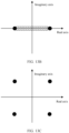
- FIG. 3C is used as an example.
- FIG. 3C shows another possible data sending scenario to which an embodiment of this application is applicable.
- FIG. 3C schematically shows four nodes: a source node (namely, an S node), two relay nodes (namely, an R1 node and an R2 node, which may also be referred to as two forwarding nodes), and a destination node (namely, a D node).
- the S node expects to send target data to the D node.
- the S node needs to first send the target data to the R1 node, the R1 node forwards the target data to the R2 node, and then the R2 node forwards the target data to the D node.
- the data sending scenario schematically shown in FIG.
- 3C may be understood as a three-hop data sending scenario, to be specific, a first hop is from the S node to the R1 node, and a second hop is from the R1 node to the R2 node, and a third hop is from the R2 node to the D node.
- FIG. 3D is used as an example.
- FIG. 3D shows another possible data sending scenario to which an embodiment of this application is applicable.
- FIG. 3C schematically shows five nodes: a source node (namely, an S node), three relay nodes (namely, an R1 node, an R2 node, and an R3 node, which may also be referred to as three forwarding nodes), and a destination node (namely, a D node).
- the S node expects to send target data to the D node.
- the S node needs to first send the target data to the R1 node, the R1 node forwards the target data to the R2 node and/or the R3 node, and then the R2 node and/or the R3 node forward/forwards the target data to the D node.
- the data sending scenario schematically shown in FIG.
- 3D may be understood as a three-hop data sending scenario, to be specific, a first hop is from the S node to the R1 node, and a second hop is from the R1 node to the R2 node and/or the R3 node, and a third hop is from the R2 node and/or the R3 node to the D node.
- FIG. 3A to FIG. 3D are merely used as examples, and a quantity of hops and a quantity of relay nodes in a multi-hop data sending scenario are not limited in the embodiments of this application.
- the source node may be a network device or a terminal
- the relay node may be a network device or a terminal
- the destination node may be a network device or a terminal.
- the embodiments of this application may also be used in a single-hop data sending scenario (to be specific, the target data is sent from a source node to a destination node).
- the forwarding node in the foregoing multi-hop data sending scenario needs to forward data to a next receiving node (where the next receiving node may be another forwarding node, or may be a destination node).
- a manner in which the forwarding node forwards the data includes decoding forwarding (decoding forwarding, DF).
- DF decoding forwarding
- a forwarding node demodulates and decodes the data, and then determines, depending on whether the decoding is correct, whether to forward the data. If the decoding is correct, the forwarding node may encode and modulate decoded data again, and send the data to a next receiving node. If the decoding is incorrect, the forwarding node does not forward the data.
- data generated through soft modulation is sent, so that when a forwarding node incorrectly decodes data of a previous sending node, the forwarding node can still forward the data, thereby improving forwarding performance.
- FIG. 4 is a schematic flowchart of a data sending method according to an embodiment of this application. It may be understood that data sent according to the data sending method in this embodiment of this application may be data including control information, may be data including service information, or may be data including both control information and service information. As shown in FIG. 4 , the method in this embodiment may include the following parts.
- Part 400 A node generates a modulation symbol based on first data and/or second data, where the modulation symbol satisfies a mapping relationship with the first data and/or the second data.
- the first data includes one or more first real numbers, and the first real number is greater than 0 and less than 1.
- the second data includes one or more second real numbers, and the second real number is greater than -1 and less than 1. That a node generates a modulation symbol based on first data and/or second data may also be understood as that the node inputs the first data and/or the second data to generate the modulation symbol.
- Part 410 The node preprocesses the modulation symbol to obtain fourth data, where the preprocessing includes one or more of layer mapping, antenna port mapping, precoding, or transform precoding.
- the foregoing preprocessing may be understood as a processing operation that needs to be completed before the modulation symbol is mapped to a physical resource.
- the node maps the fourth data to the physical resource, and sends the fourth data on the physical resource.
- the physical resource may include one or more of a time domain resource, a frequency domain resource, a code domain resource, or a space domain resource.
- the time domain resource included in the physical resource may include at least one frame, at least one subframe, at least one slot, at least one mini-slot (mini-slot), or at least one time domain symbol.
- the frequency domain resource included in the physical resource may include at least one carrier (carrier), at least one component carrier (component carrier, CC), at least one bandwidth part (bandwidth part, BWP), at least one resource block group (resource block group, RBG), at least one physical resource block group (physical resource-block group, PRG), at least one resource block (resource block, RB), or at least one subcarrier (sub-carrier, SC).
- the space domain resource included in the physical resource may include at least one beam, at least one port, at least one antenna port, or at least one layer/space layer.
- the code domain resource included in the physical resource may include at least one orthogonal cover code (orthogonal cover code, OCC), or at least one non-orthogonal multiple access (non-orthogonal multiple access, NOMA) code.
- FIG. 4 may be understood as a method for performing soft modulation and sending a modulation symbol generated through soft modulation.
- FIG. 5 is a schematic block diagram of performing soft modulation and sending a modulation symbol generated through soft modulation according to an embodiment of this application.
- a soft modulation process is as follows: Soft information is input for modulation and a modulation symbol is output. It may be understood that, in this embodiment of this application, the modulation symbol obtained through soft modulation is also referred to as a soft modulation symbol sometimes.
- the soft modulation symbol is preprocessed (where a preprocessing process includes one or more of layer mapping, antenna port mapping, precoding, or transform precoding) to obtain to-be-sent data, the to-be-sent data is mapped to a physical resource (that is, resource mapping is performed), and the to-be-sent data is sent on the physical resource.
- the soft information schematically shown in FIG. 5 may be soft information directly obtained by a forwarding node in a process of demodulating or decoding data of a previous sending node, or may be soft information further obtained after soft information directly obtained in a demodulation or decoding process is processed.
- the soft information directly obtained in the data demodulation process may represent reliability of a modulation bit obtained through demodulation, and the soft information directly obtained in the data decoding process may represent reliability of a system bit and a check bit obtained through decoding.
- the forwarding node may still perform modulation (namely, soft modulation) on the soft information obtained in the demodulation and/or decoding process (where the soft information may be soft information directly obtained in the demodulation and/or decoding process, or may be the soft information further obtained after the soft information directly obtained in the demodulation and/or decoding process is processed), to obtain the soft modulation symbol, and then forward the soft modulation symbol generated through soft modulation, thereby improving forwarding performance.
- modulation namely, soft modulation
- the first data and/or the second data in part 400 may be understood as the soft information in FIG. 5 .
- the first data includes one or more first real numbers, and the first real number is greater than 0 and less than 1.
- the first real number may also be referred to as soft bit information (namely, a possible form of the soft information schematically shown in FIG. 5 ).
- a value of common bit information is 0 or 1, but the soft bit information in this embodiment of this application is a real number value between 0 and 1.
- the second data includes one or more second real numbers, and the second real number is greater than -1 and less than 1.
- the second real number may also be referred to as soft symbol information (namely, a possible form of the soft information schematically shown in FIG. 5 ).
- a value of common symbol information is -1 or 1, but the soft symbol information in this embodiment of this application is a real number value between -1 and 1.
- mapping relationship may be understood as a mapping relationship implemented by a modulation module in FIG. 5 .
- the modulation symbol satisfies a mapping relationship with the first data.
- the mapping relationship may be understood as a mapping relationship that the modulation symbol satisfies with the first data when the modulation module in FIG. 5 uses a binary phase shift keying (binary phase shift keying, BPSK) modulation scheme.
- BPSK binary phase shift keying
- the node inputs the first real number b ⁇ 0 based on the mapping relationship, and generates a complex number modulation symbol Q ⁇ .
- the soft modulation may be implemented by using the BPSK modulation scheme, thereby reducing implementation complexity of the soft modulation.
- the mapping relationship may be understood as a mapping relationship that the modulation symbol satisfies with the first data when the modulation module in FIG. 5 uses a quadrature phase shift keying (quadrature phase shift keying, QPSK) modulation scheme.
- the node inputs the first real numbers b ⁇ 0 and b ⁇ 1 based on the mapping relationship, and generates a complex number modulation symbol Q ⁇ .
- the soft modulation may be implemented by using the QPSK modulation scheme, thereby reducing the implementation complexity of the soft modulation.
- the mapping relationship may be understood as a mapping relationship that the modulation symbol satisfies with the first data when the modulation module in FIG. 5 uses a 16 quadrature amplitude modulation (16 quadrature amplitude modulation, 16QAM) modulation scheme.
- the node inputs the first real numbers b ⁇ 0 , b ⁇ 1 , b ⁇ 2 , and b ⁇ 3 based on the mapping relationship, and generates a complex number modulation symbol Q ⁇ . It may be understood that a value relationship between the first real numbers b ⁇ 0 , b ⁇ 1 , b ⁇ 2 , and b ⁇ 3 is not limited in this application. According to the foregoing example method, the soft modulation may be implemented by using the 16QAM modulation scheme, thereby reducing the implementation complexity of the soft modulation.
- the mapping relationship may be understood as a mapping relationship that the modulation symbol satisfies with the first data when the modulation module in FIG. 5 uses a 64 quadrature amplitude modulation (64 quadrature amplitude modulation, 64QAM) modulation scheme.
- the node inputs the first real numbers b ⁇ 0 , b ⁇ 1 , b ⁇ 2 , b ⁇ 3 , b ⁇ 4 , and b ⁇ 5 based on the mapping relationship, and generates a complex number modulation symbol Q ⁇ .
- a value relationship between the first real numbers b ⁇ 0 , b ⁇ 1 , b ⁇ 2 , b ⁇ 3 , b ⁇ 4 , and b ⁇ 5 is not limited in this application.
- the soft modulation may be implemented by using the 64QAM modulation scheme, thereby reducing the implementation complexity of the soft modulation.
- mapping relationship in the foregoing implementation may alternatively be a mapping relationship that the modulation symbol satisfies with the first data and that corresponds to another modulation scheme.
- the another modulation scheme may be 256QAM, 512QAM, 1024QAM, or pi/2-BPSK. This is not limited in this embodiment of this application.
- the modulation symbol satisfies a mapping relationship with the second data.
- the mapping relationship may be understood as a mapping relationship that the modulation symbol satisfies with the second data when the modulation module in FIG. 5 uses the BPSK modulation scheme.
- the node inputs the second real number ⁇ 0 based on the mapping relationship, and generates a complex number modulation symbol Q ⁇ .
- the soft modulation may be implemented by using the BPSK modulation scheme, thereby reducing the implementation complexity of the soft modulation.
- the mapping relationship may be understood as a mapping relationship that the modulation symbol satisfies with the second data when the modulation module in FIG. 5 uses the QPSK modulation scheme.
- the node inputs the second real numbers ⁇ 0 and ⁇ 1 based on the mapping relationship, and generates a complex number modulation symbol Q ⁇ . It may be understood that ⁇ 0 may not be equal to ⁇ 1 , or may be equal to ⁇ 1 .
- a value relationship between the second real numbers ⁇ 0 and ⁇ 1 is not limited in this application.
- the soft modulation may be implemented by using the QPSK modulation scheme, thereby reducing the implementation complexity of the soft modulation.
- the mapping relationship may be understood as a mapping relationship that the modulation symbol satisfies with the second data when the modulation module in FIG. 5 uses the 16QAM modulation scheme.
- the node inputs the second real numbers ⁇ 0 , ⁇ 1 , ⁇ 2 , and ⁇ 3 based on the mapping relationship, and generates a complex number modulation symbol Q ⁇ . It may be understood that a value relationship between the second real numbers ⁇ 0 , ⁇ 1 , ⁇ 2 , and ⁇ 3 is not limited in this application. According to the foregoing example method, the soft modulation may be implemented by using the 16QAM modulation scheme, thereby reducing the implementation complexity of the soft modulation.
- the mapping relationship may be understood as a mapping relationship that the modulation symbol satisfies with the second data when the modulation module in FIG. 5 uses the 64QAM modulation scheme.
- the node inputs the second real numbers ⁇ 0 , ⁇ 1 , ⁇ 2 , ⁇ 3 , ⁇ 4 , and ⁇ 5 based on the mapping relationship, and generates a complex number modulation symbol Q ⁇ . It may be understood that a value relationship between the second real numbers ⁇ 0 , ⁇ 1 , ⁇ 2 , ⁇ 3 , ⁇ 4 , and ⁇ 5 is not limited in this application. According to the foregoing example method, the soft modulation may be implemented by using the 64QAM modulation scheme, thereby reducing the implementation complexity of the soft modulation.
- mapping relationship in the foregoing implementation may alternatively be a mapping relationship that the modulation symbol satisfies with the second data and that corresponds to another modulation scheme.
- the another modulation scheme may be 256QAM, 512QAM, 1024QAM, or pi/2-BPSK. This is not limited in this embodiment of this application.
- the modulation symbol satisfies a mapping relationship with the first data and the second data.
- the mapping relationship may be understood as a mapping relationship that the modulation symbol satisfies with the first data and the second data when the modulation module in FIG. 5 uses the QPSK modulation scheme.
- the node inputs the first real number b ⁇ 0 and the second real number ⁇ 0 based on the mapping relationship, and generates a complex number modulation symbol Q ⁇ .
- ⁇ 0 may not be equal to b ⁇ 0 , or may be equal to b ⁇ 0 .
- a value relationship between the first real number b ⁇ 0 and the second real number ⁇ 0 is not limited in this application.
- the soft modulation may be implemented by using the QPSK modulation scheme, thereby reducing the implementation complexity of the soft modulation.
- the mapping relationship may be understood as a mapping relationship that the modulation symbol satisfies with the first data and the second data when the modulation module in FIG. 5 uses the 16QAM modulation scheme.
- the node inputs the first real numbers b ⁇ 0 and b ⁇ 1 and the second real numbers ⁇ 2 and ⁇ 3 based on the mapping relationship, and generates a complex number modulation symbol Q ⁇ . It may be understood that a value relationship between the first real numbers b ⁇ 0 and b ⁇ 1 and the second real numbers ⁇ 2 and ⁇ 3 is not limited in this application. According to the foregoing example method, the soft modulation may be implemented by using the 16QAM modulation scheme, thereby reducing the implementation complexity of the soft modulation.
- the mapping relationship in the foregoing implementation may alternatively be a mapping relationship that the modulation symbol satisfies with the first data and the second data and that corresponds to another modulation scheme.
- the another modulation scheme may be BPSK, 64QAM, 256QAM, 512QAM, 1024QAM, or pi/2-BPSK. This is not limited in this embodiment of this application.
- specific locations of the first data and the second data in the mapping relationship are not limited in the foregoing implementation. Both the first data and the second data fall within the protection scope of the embodiments of this application, provided that both the first data and the second data exist in the mapping relationship.
- the first data may further include one or more third real numbers, and the third real number is equal to 0 or 1.
- the second data may further include one or more fourth real numbers, and the fourth real number is equal to -1 or 1.
- the first data includes one or more of the foregoing first real numbers and one or more of the third foregoing real numbers, and the first data may be considered as soft bit information (namely, a possible form of the soft information schematically shown in FIG. 5 ).
- the second data includes one or more of the foregoing second real numbers and one or more of the foregoing fourth real numbers, and the second data may be considered as soft symbol information (namely, a possible form of the soft information schematically shown in FIG. 5 ).
- the modulation symbol satisfies a mapping relationship with the first data that includes one or more of the foregoing first real numbers and one or more of the foregoing third real numbers.
- b ⁇ 0 is the first real number and b ⁇ 1 is the third real number
- b ⁇ 0 is the third real number
- b ⁇ 1 is the first real number.
- the mapping relationship may be understood as a mapping relationship that the modulation symbol satisfies with the first data when the modulation module in FIG. 5 uses the QPSK modulation scheme.
- the node inputs the first data b ⁇ 0 and b ⁇ 1 based on the mapping relationship, and generates a complex number modulation symbol Q ⁇ .
- the soft modulation may be implemented by using the QPSK modulation scheme, thereby reducing the implementation complexity of the soft modulation.
- b ⁇ 0 and b ⁇ 1 are the first real numbers and b ⁇ 2 and b ⁇ 3 are the third real numbers, or b ⁇ 0 and b ⁇ 1 are the third real numbers and b ⁇ 2 and b ⁇ 3 are the first real numbers.
- the mapping relationship may be understood as a mapping relationship that the modulation symbol satisfies with the first data when the modulation module in FIG. 5 uses the 16QAM modulation scheme.
- the node inputs the first data b ⁇ 0 , b ⁇ 1 , b ⁇ 2 , and b ⁇ 3 based on the mapping relationship, and generates a complex number modulation symbol Q ⁇ .
- the soft modulation may be implemented by using the 16QAM modulation scheme, thereby reducing the implementation complexity of the soft modulation.
- b ⁇ 0 , b ⁇ 1 , and b ⁇ 2 are the first real numbers and b ⁇ 3 , b ⁇ 4 , and b ⁇ 5 are the third real numbers, or b ⁇ 0 , b ⁇ 1 , and b ⁇ 2 are the third real numbers and b ⁇ 3 , b ⁇ 4 , and b ⁇ 5 are the first real numbers. It may be understood that, in the foregoing six real numbers b ⁇ 0 , b ⁇ 1 , b ⁇ 2 , b ⁇ 3 , b ⁇ 4 , and b ⁇ 5 , specifically which real numbers are first real numbers and which real numbers are third real numbers are not limited in this embodiment of this application.
- the mapping relationship may be understood as a mapping relationship that the modulation symbol satisfies with the first data when the modulation module in FIG. 5 uses the 64QAM modulation scheme.
- the node inputs the first data b ⁇ 0 , b ⁇ 1 , b ⁇ 2 , b ⁇ 3 , b ⁇ 4 , and b ⁇ 5 based on the mapping relationship, and generates a complex number modulation symbol Q ⁇ .
- the soft modulation may be implemented by using the 64QAM modulation scheme, thereby reducing the implementation complexity of the soft modulation.
- mapping relationship in the foregoing implementation may alternatively be a mapping relationship that the modulation symbol satisfies with the first data and that corresponds to another modulation scheme.
- the another modulation scheme may be 256QAM, 512QAM, or 1024QAM. This is not limited in this embodiment of this application.
- the modulation symbol satisfies a mapping relationship with the second data that includes one or more of the foregoing second real numbers and one or more of the foregoing fourth real numbers.
- ⁇ 0 is the second real number and ⁇ 1 is the fourth real number, or ⁇ 0 is the fourth real number and ⁇ 1 is the second real number.
- the mapping relationship may be understood as a mapping relationship that the modulation symbol satisfies with the second data when the modulation module in FIG. 5 uses the QPSK modulation scheme.
- the node inputs the second data ⁇ 0 and ⁇ 1 based on the mapping relationship, and generates a complex number modulation symbol Q ⁇ .
- the soft modulation may be implemented by using the QPSK modulation scheme, thereby reducing the implementation complexity of the soft modulation.
- ⁇ 0 and ⁇ 1 are the second real numbers and ⁇ 2 and ⁇ 3 are the fourth real numbers, or ⁇ 0 and ⁇ 1 are the fourth real numbers and ⁇ 2 and ⁇ 3 are the second real numbers.
- the mapping relationship may be understood as a mapping relationship that the modulation symbol satisfies with the second data when the modulation module in FIG. 5 uses the 16QAM modulation scheme.
- the node inputs the second data ⁇ 0 , ⁇ 1 , ⁇ 2 , and ⁇ 3 based on the mapping relationship, and generates a complex number modulation symbol Q ⁇ .
- the soft modulation may be implemented by using the 16QAM modulation scheme, thereby reducing the implementation complexity of the soft modulation.
- ⁇ 0 , ⁇ 1 , and ⁇ 2 are the second real numbers and ⁇ 3 , ⁇ 4 , and ⁇ 5 are the fourth real numbers, or ⁇ 0 , ⁇ 1 , and ⁇ 2 are the fourth real numbers and ⁇ 3 , ⁇ 4 , and ⁇ 5 are the second real numbers.
- the mapping relationship may be understood as a mapping relationship that the modulation symbol satisfies with the second data when the modulation module in FIG.
- the soft modulation may be implemented by using the 64QAM modulation scheme, thereby reducing the implementation complexity of the soft modulation.
- mapping relationship in the foregoing implementation may alternatively be a mapping relationship that the modulation symbol satisfies with the second data and that corresponds to another modulation scheme.
- the another modulation scheme may be 256QAM, 512QAM, or 1024QAM. This is not limited in this embodiment of this application.
- a node generates a modulation symbol based on first data and second data, where the modulation symbol satisfies a mapping relationship with the first data and the second data, the first data includes one or more first real numbers, the first real number is greater than 0 and less than 1, the second data includes one or more fourth real numbers, and the fourth real number is equal to -1 or 1.
- a node generates a modulation symbol based on first data and second data, where the modulation symbol satisfies a mapping relationship with the first data and the second data, the first data includes one or more third real numbers, the third real number is equal to 0 or 1, the second data includes one or more second real numbers, and the second real number is greater than -1 and less than 1.
- a node generates a modulation symbol based on first data and second data, where the modulation symbol satisfies a mapping relationship with the first data and the second data, the first data includes one or more first real numbers, the first real number is greater than 0 and less than 1, the second data includes one or more second real numbers and one or more fourth real numbers, the second real number is greater than -1 and less than 1, and the fourth real number is equal to -1 or 1.
- a node generates a modulation symbol based on first data and second data, where the modulation symbol satisfies a mapping relationship with the first data and the second data, the first data includes one or more first real numbers and one or more third real numbers, the first real number is greater than 0 and less than 1, the third real number is equal to 0 or 1, the second data includes one or more second real numbers, and the second real number is greater than -1 and less than 1.
- a node generates a modulation symbol based on first data and second data, where the modulation symbol satisfies a mapping relationship with the first data and the second data, the first data includes one or more first real numbers and one or more third real numbers, the first real number is greater than 0 and less than 1, the third real number is equal to 0 or 1, the second data includes one or more second real numbers and one or more fourth real numbers, the second real number is greater than -1 and less than 1, and the fourth real number is equal to -1 or 1.
- mapping relationship in the foregoing 400a to 400e may be understood as a mapping relationship implemented by the modulation module in FIG. 5 .
- mapping relationship For specific descriptions of the mapping relationship, refer to the descriptions of the mapping relationship in the foregoing part 400. Details are not described herein again.
- the node may obtain the first data and/or the second data based on third data.
- the third data may be understood as original soft information obtained by the node by demodulating or decoding data of a previous sending node.
- the third data includes one or more fifth real numbers, and a value range of the fifth real number is from A to B. It may be understood that a range from A to B is generally greater than a range from 0 to 1 or a range from -1 to 1. For example, A indicates negative infinity and B indicates positive infinity, or A indicates -30 and B indicates 30. Specific values of A and B are not limited in this embodiment of this application.
- original soft information for example, a value range from negative infinity to positive infinity
- original soft information may be compressed to be within a range from 0 to 1, so that complexity of a subsequent operation (for example, modulation) can be reduced.
- the node quantizes the third data to obtain the first data.
- the third data may be quantized by using the table schematically shown in Table 1, to obtain the first data.
- the left column in Table 1 schematically shows several value intervals of the third data L (which may also be understood as a fifth real number included in the third data), where A and B respectively represent a lower limit value and an upper limit value of L, c k represents a positive real number, - c k represents a negative real number, k is an integer greater than or equal to 0 and less than or equal to N, [ a , b ] represents that the value interval is greater than or equal to a and less than or equal to b, and [ a , b ) represents that a value interval is greater than or equal to a and less than b.
- the right column in Table 1 schematically shows several values of the first data b ⁇ i (which may also be understood as a first real number or a third real number included in the first data), where d l represents a real number greater than or equal to 0 and less than or equal to 1, and l is an integer greater than or equal to 0 and less than or equal to 2N.
- the node obtains the third data L, determines a value interval, in the left column of Table 1, within which a value of the third data L falls, and determines that a value, in the right column of Table 1, corresponding to the value interval is a value, of the first data b ⁇ i , obtained after the third data L is quantized.
- Table 1 schematically shows only a possible representation form of a correspondence between the third data L and the first data b ⁇ i .
- a specific representation form of the correspondence between the third data L and the first data b ⁇ i is not limited in this embodiment of this application, and another possible representation form of the correspondence also falls within the protection scope of the embodiments of this application.
- the value intervals of the third data L schematically shown in Table 1 may be obtained by evenly dividing an interval [A, B ], or may be obtained by unevenly dividing the interval [A, B ] . This is not limited in this embodiment of this application.
- original soft information for example, a value range from negative infinity to positive infinity
- original soft information may be compressed to be within a range from 0 to 1 in a simple manner of quantization, so that the forwarding node does not need to perform a complex operation, and complexity of a subsequent operation (for example, modulation) can be reduced.
- Table 1 Value interval of the third data L (which may also be understood as a fifth real number included in the third data) Value of the first data b ⁇ i (which may also be understood as a first real number or a third real number included in the first data) [ c N , B ] d 2 N [ c N -1 , c N ) d 2 N -1 ... ... [- c N , - c N -1 ) d 1 [ A , - c N ) d 0
- original soft information for example, a value range from negative infinity to positive infinity
- original soft information may be compressed to be within a range from -1 to 1, so that complexity of a subsequent operation (for example, modulation) can be reduced.
- the node quantizes the third data to obtain the second data.
- the third data may be quantized by using the table schematically shown in Table 2, to obtain the second data.
- the left column in Table 2 schematically shows several value intervals of the third data L (which may also be understood as a fifth real number included in the third data), where A' and B' respectively represent a lower limit value and an upper limit value of L, c k ′ represents a positive real number, ⁇ c k ′ represents a negative real number, k is an integer greater than 0 and less than or equal to N, [ a' , b' ] represents that the value interval is greater than or equal to a' and less than or equal to b', and [ a' , b' ) represents that a value interval is greater than or equal to a' and less than b'.
- the right column in Table 2 schematically shows several values of the second data ⁇ i (which may also be understood as a second real number or a fourth real number included in the second data), where d l ′ represents a real number greater than or equal to 0 and less than or equal to 1, ⁇ d l ′ represents a real number greater than or equal to -1 and less than or equal to 0, and l is an integer greater than or equal to 0 and less than or equal to N'.
- the node obtains the third data L, determines a value interval, in the left column of Table 2, within which a value of the third data L falls, and determines that a value, in the right column of Table 2, corresponding to the value interval is a value, of the second data ⁇ i , obtained after the third data L is quantized.
- Table 2 schematically shows only a possible representation form of a correspondence between the third data L and the second data ⁇ i .
- a specific representation form of the correspondence between the third data L and the second data ⁇ i is not limited in this embodiment of this application, and another possible representation form of the correspondence also falls within the protection scope of the embodiments of this application.
- the value intervals of the third data L schematically shown in Table 2 may be obtained by evenly dividing an interval [ A' , B ' ] , or may be obtained by unevenly dividing the interval [ A' , B' ].
- original soft information for example, a value range from negative infinity to positive infinity
- original soft information that is obtained by the forwarding node and that has a large value range may be compressed to be within a range from -1 to 1 in a simple manner of quantization, so that the forwarding node does not need to perform a complex operation, and complexity of a subsequent operation (for example, modulation) can be reduced.
- Table 2 Value interval of the third data L (which may also be understood as a fifth real number included in the third data) Value of the second data ⁇ i (which may also be understood as a second real number or a fourth real number included in the second data) c N ′ ′ , B ′ d N ′ ′ c N ′ ⁇ 1 ′ c N ′ ′ d N ′ ⁇ 1 ′ ... ... c 1 ′ c 2 ′ d 1 ′ ⁇ c 1 ′ , c 1 ′ d 0 ′ ⁇ c 2 ′ , ⁇ c 1 ′ ⁇ d 1 ′ ... ...
- original soft information for example, a value range from negative infinity to positive infinity
- original soft information may be compressed to be within a range from 0 to 1 and a range from -1 to 1, so that complexity of a subsequent operation (for example, modulation) can be reduced.
- the node quantizes the third data to obtain the first data and the second data.
- the tables schematically shown in Table 1 and Table 2 may be used to quantize the third data to obtain the first data and the second data.
- Table 1 and Table 2 For a specific quantization process, refer to the foregoing descriptions of Table 1 and Table 2. Details are not described herein again.
- original soft information for example, a value range from negative infinity to positive infinity
- original soft information that is obtained by the forwarding node and that has a large value range
- the table schematically shown in Table 1 may be used to quantize the third data to obtain the first data. For a specific quantization process, refer to the foregoing descriptions of Table 1.
- original soft information for example, a value range from negative infinity to positive infinity
- original soft information may be compressed to be within a range from 0 to 1 and a range from -1 to 1, so that the forwarding node does not need to perform a complex operation, and complexity of a subsequent operation (for example, modulation) can be reduced.
- the table schematically shown in Table 2 may be used to quantize the third data to obtain the second data.
- original soft information for example, a value range from negative infinity to positive infinity
- original soft information may be compressed to be within a range from 0 to 1 and a range from -1 to 1, so that the forwarding node does not need to perform a complex operation, and complexity of a subsequent operation (for example, modulation) can be reduced.
- the node may enable or disable the foregoing soft modulation operation.
- the node receives control information, and determines, based on the control information, to generate the modulation symbol based on the first data and/or the second data.
- the control information may be understood as having a function of controlling the enabling or disabling of the foregoing soft modulation. If the control information indicates a node to use the soft modulation, the node modulates the first data and/or the second data according to the foregoing soft modulation method in this embodiment of this application, to generate the modulation symbol (which may be understood as a soft modulation symbol).
- the node modulates a common bit (which may be understood as a hard bit, namely, 0 or 1) and/or a common symbol (which may be understood as a hard symbol, namely, -1 or 1), to generate a common modulation symbol (which may be understood as a hard modulation symbol).
- a common bit which may be understood as a hard bit, namely, 0 or 1
- a common symbol which may be understood as a hard symbol, namely, -1 or 1
- the node can be notified to use a proper modulation scheme, thereby improving robustness of data sending.
- the control information may be included in a physical layer message/information or a higher layer message/information.
- the control information may be included in a physical layer message/information.
- the physical layer message/information may be, for example, downlink control information (downlink control information, DCI) from a network device, or may be, for example, sidelink control information (sidelink control information, SCI) or uplink control information (uplink control information, UCI) from a terminal.
- DCI downlink control information
- SCI sidelink control information
- UCI uplink control information
- control information may be included in a higher layer message/information
- the higher layer message/information may be, for example, a media access control (media access control, MAC) layer message or a radio resource control (radio resource control, RRC) layer message from the network device or the terminal.
- media access control media access control
- RRC radio resource control
- FIG. 6 is a flowchart of the implementation.
- a node receives control information. If the control information indicates a first status, the node performs hard modulation (performs part 610, to be specific, the node modulates a common bit and/or a common symbol to generate a common modulation symbol). If the control information indicates a second status, the node performs soft modulation (performs part 620, to be specific, the node modulates the foregoing first data and/or second data to generate a soft modulation symbol).
- control information includes modulation scheme indication information
- the modulation scheme indication information indicates the first status or the second status.
- the modulation scheme indication information includes at least one bit, the first status is indicated when a value of the at least one bit is a first value, the second status is indicated when a value of the at least one bit is a second value, and the first value is different from the second value.
- the modulation scheme indication information includes one bit, a value "0" of the bit indicates the first status, and a value "1" of the bit indicates the second status.
- a value "1" of the bit indicates the first status
- a value "0" of the bit indicates the second status. It may be understood that the implementation of the modulation scheme indication information may be considered as that the modulation scheme indication information explicitly indicates the first status or the second status.
- the control information includes a newly added data field (where for example, the data field may be referred to as a modulation scheme indication field) used to carry the modulation scheme indication information, and the node may obtain the modulation scheme indication information by parsing bit data carried in the data field.
- a modulation scheme indication field used to carry the modulation scheme indication information
- an existing data field in the control information is reused to carry the modulation scheme indication information.
- the existing data field is reused to carry the modulation scheme indication information, so that no bit of the control information needs to be newly added, thereby reducing indication overheads.
- one or more bits in a modulation and coding scheme (modulation coding scheme, MCS) indication field in the DCI or the SCI may be reused to carry the modulation scheme indication information.
- one or more bits in a BWP indication field in the DCI or the SCI may be reused to carry the modulation scheme indication information.
- one or more bits in a reserved field in the DCI or the SCI may be reused to carry the modulation scheme indication information.
- one or more bits in an MCS indication field in the DCI or the SCI and one or more bits in a BWP indication field in the DCI or the SCI may be reused to carry the modulation scheme indication information.
- one or more bits in an MCS indication field in the DCI or the SCI and one or more bits in a reserved field in the DCI or the SCI may be reused to carry the modulation scheme indication information.
- one or more bits in a BWP indication field in the DCI or the SCI and one or more bits in a reserved field in the DCI or the SCI may be reused to carry the modulation scheme indication information.
- one or more bits in an MCS indication field in the DCI or the SCI, one or more bits in a BWP indication field in the DCI or the SCI, and one or more bits in a reserved field in the DCI or the SCI may be reused to carry the modulation scheme indication information.
- one or more bits in an acknowledgment indication field (for example, a data field carrying an acknowledgment (acknowledgement, ACK)/a negative acknowledgment (negative acknowledgment, NACK)) in the DCI, the UCI, or the SCI may be reused to carry the modulation scheme indication information.
- an acknowledgment indication field for example, a data field carrying an acknowledgment (acknowledgement, ACK)/a negative acknowledgment (negative acknowledgment, NACK)
- ACK acknowledgment
- NACK negative acknowledgment
- the modulation scheme indication information includes a bit sequence, the bit sequence is used to scramble the control information, the first status is indicated when the bit sequence is a first bit sequence, the second status is indicated when the bit sequence is a second bit sequence, and the first bit sequence is different from the second bit sequence. That the first bit sequence is different from the second bit sequence may also be understood as that an initial value of the first bit sequence is different from an initial value of the second bit sequence, or that a parameter of an initial value of the first bit sequence is different from a parameter of an initial value of the second bit sequence. It may be understood that the implementation of the modulation scheme indication information may be considered as that the modulation scheme indication information implicitly indicates the first status or the second status. In the implementation, the modulation scheme indication information is implicitly included in the scrambling sequence of the control information, so that no bit of the control information needs to be newly added, thereby reducing indication overheads.
- the modulation scheme indication information includes a physical resource, the control information is mapped to the physical resource, the first status is indicated when the physical resource is a first physical resource, the second status is indicated when the physical resource is a second physical resource, and the first physical resource is different from the second physical resource. It may be understood that the implementation of the modulation scheme indication information may be considered as that the modulation scheme indication information implicitly indicates the first status or the second status. In the implementation, the modulation scheme indication information is implicitly included in the physical resource that carries the control information, so that no bit of the control information needs to be newly added, thereby reducing indication overheads.
- the control information includes the modulation scheme indication information and identification information that is of the node, the identification information of the node indicates the node, and the modulation scheme indication information indicates the first status or the second status.
- the identification information of the node indicates the node. The node receives the control information, and parses out the identification information of the node from the control information, to learn that the control information is sent to the node.
- the identification information of the node may also indicate a group of nodes, the group of nodes includes a plurality of nodes, and any one or more of the plurality of nodes receive the control information and parse out the identification information of the node from the control information, to learn that the control information is sent to the one or more nodes.
- the identification information of the node includes at least one bit, and the node may obtain the identification information of the node by parsing a value of the at least one bit.
- the identification information of the node may be an identifier or an index of the node, and the identifier or the index is used to indicate the node.
- the identification information of the node may alternatively be one or more bits in some bits in a bitmap, and the node is indicated by using the one or more bits in the bits. It may be understood that the implementation may be considered as that the identification information of the node explicitly indicates the node.
- the control information includes a newly added data field (where for example, the data field may be referred to as a node indication field) used to carry the identification information of the node, and the node may obtain the identification information of the node by parsing bit data carried in the data field.
- an existing data field in the control information is reused to carry the identification information of the node.
- the existing data field is reused to carry the identification information of the node, so that no bit of the control information needs to be newly added, thereby reducing indication overheads.
- one or more bits in an MCS indication field in the DCI or the SCI may be reused to carry the identification information of the node.
- one or more bits in a BWP indication field in the DCI or the SCI may be reused to carry the identification information of the node.
- one or more bits in a reserved field in the DCI or the SCI may be reused to carry the identification information of the node.
- one or more bits in an MCS indication field in the DCI or the SCI and one or more bits in a BWP indication field in the DCI or the SCI may be reused to carry the identification information of the node.
- one or more bits in an MCS indication field in the DCI or the SCI and one or more bits in a reserved field in the DCI or the SCI may be reused to carry the identification information of the node.
- one or more bits in a BWP indication field in the DCI or the SCI and one or more bits in a reserved field in the DCI or the SCI may be reused to carry the identification information of the node.
- one or more bits in an MCS indication field in the DCI or the SCI, one or more bits in a BWP indication field in the DCI or the SCI, and one or more bits in a reserved field in the DCI or the SCI may be reused to carry the identification information of the node.
- one or more bits in an acknowledgment indication field for example, a data field carrying an ACK/a NACK
- the DCI, the UCI, or the SCI may be reused to carry the identification information of the node.
- the identification information of the node includes a bit sequence, the bit sequence is used to scramble the control information, and the node may obtain the identification information of the node by parsing the bit sequence. It may be understood that the implementation may be considered as that the identification information of the node implicitly indicates the node. In the implementation, the identification information of the node is implicitly included in the scrambling sequence of the control information, so that no bit of the control information needs to be newly added, thereby reducing indication overheads.
- the identification information of the node includes a physical resource, the control information is mapped to the physical resource, and the node may obtain the identification information of the node by receiving the control information on the physical resource. It may be understood that the implementation may be considered as that the identification information of the node implicitly indicates the node. In the implementation, the identification information of the node is implicitly included in the physical resource that carries the control information, so that no bit of the control information needs to be newly added, thereby reducing indication overheads.
- FIG. 7 is a flowchart of the implementation.
- a node determines whether control information is received. If the node does not receive the control information, the node performs hard modulation (performs part 710, to be specific, the node modulates a common bit and/or a common symbol to generate a common modulation symbol).
- the node performs soft modulation (performs part 720, to be specific, the node modulates the foregoing first data and/or second data to generate a soft modulation symbol). It may be understood that locations of part 710 and part 720 in FIG. 7 may alternatively be interchanged, to be specific, the node may perform soft modulation (perform part 720, to be specific, the node modulates the foregoing first data and/or second data to generate a soft modulation symbol) when the control information is not received, or perform hard modulation (perform part 710, to be specific, the node modulates a common bit and/or a common symbol to generate a common modulation symbol) when the control information is received.
- the control information includes identification information of the node, and the identification information of the node indicates the node.
- the control information includes modulation scheme indication information, and the modulation scheme indication information indicates the node to perform soft modulation (where it may be understood that the modulation scheme indication information may alternatively indicate the node to perform hard modulation).
- the modulation scheme indication information may alternatively indicate the node to perform hard modulation.
- the control information includes modulation scheme indication information and identification information that is of the node, the identification information of the node indicates the node, and the modulation scheme indication information indicates the node to perform soft modulation (where it may be understood that the modulation scheme indication information may alternatively indicate the node to perform hard modulation).
- modulation scheme indication information refer to the descriptions of the modulation scheme indication information in the implementation schematically shown in FIG. 6 .
- identification information of the node refer to the descriptions of the identification information of the node in the implementation schematically shown in FIG. 6 . Details are not described herein again.
- the sender of the control information is an upper-level node of the node.
- the upper-level node of the node may be understood as a previous-hop node or a previous-several-hop node of the node.
- FIG. 8A shows an example in which the sender of the control information is an upper-level node of the node.
- an R1 node is a node that receives the control information
- an S node is a node that sends the control information
- the S node is a previous-hop node of the R1 node.
- FIG. 8B shows another example in which the sender of the control information is an upper-level node of the node.
- an R1 node and an R2 node are nodes that receive the control information
- an S node is a node that sends the control information
- the S node is a previous-hop node of the R1 node and the R2 node.
- FIG. 8C shows another example in which the sender of the control information is an upper-level node of the node.
- an R2 node is a node that receives the control information
- an S node is a node that sends the control information
- the S node is a previous-two-hop node of the R2 node.
- FIG. 8D shows another example in which the sender of the control information is an upper-level node of the node.
- an R2 node and an R3 node are nodes that receive the control information
- an S node is a node that sends the control information
- the S node is a previous-two-hop node of the R2 node and the R3 node.
- FIG. 8E shows another example in which the sender of the control information is an upper-level node of the node.
- an R2 node is a node that receives the control information
- an R1 node is a node that sends the control information
- the R1 node is a previous-hop node of the R2 node.
- FIG. 8F shows another example in which the sender of the control information is an upper-level node of the node.
- an R2 node and an R3 node are nodes that receive the control information
- an R1 node is a node that sends the control information
- the R1 node is a previous-hop node of the R2 node and the R3 node.
- the upper-level node of the node may send, in any one of the following cases to the node, the control information used to indicate the node to enable soft modulation:
- the sender of the control information is a same-level node of the node.
- the same-level node of the node may be understood as a same-hop node of the node.
- FIG. 9A shows an example in which the sender of the control information is a same-level node of the node.
- an R1 node is a node that receives the control information
- an R2 node is a node that sends the control information
- the R2 node and the R1 node are same-hop nodes.
- FIG. 9B shows another example in which the sender of the control information is a same-level node of the node.
- an R2 node is a node that receives the control information
- an R3 node is a node that sends the control information
- the R2 node and the R3 node are same-hop nodes.
- FIG. 9C shows another example in which the sender of the control information is a same-level node of the node.
- an S1 node is a node that receives the control information
- an S2 node is a node that sends the control information
- the S1 node and the S2 node are same-hop nodes.
- the same-level node of the node may send, in any one of the following cases to the node, the control information used to indicate the node to enable soft modulation:
- the same-level node of the node may send, in any one of the following cases to the node, the control information used to indicate the node to disable the soft modulation (that is, enable the hard modulation):
- the sender of the control information is a lower-level node of the node.
- the lower-level node of the node may be understood as a next-hop node or a next-several-hop node of the node.
- FIG. 10A shows an example in which the sender of the control information is a lower-level node of the node.
- an R1 node is a node that receives the control information
- a D node is a node that sends the control information
- the D node is a next-hop node of the R1 node.
- FIG. 10B shows another example in which the sender of the control information is a lower-level node of the node.
- an R1 node and an R2 node are nodes that receive the control information
- a D node is a node that sends the control information
- the D node is a next-hop node of the R1 node and the R2 node.
- FIG. 10C shows another example in which the sender of the control information is a lower-level node of the node.
- an R1 node is a node that receives the control information
- a D node is a node that sends the control information
- the D node is a next-two-hop node of the R1 node.
- FIG. 10D shows another example in which the sender of the control information is a lower-level node of the node.
- an R1 node and an R2 node are nodes that receive the control information
- a D node is a node that sends the control information
- the D node is a next-two-hop node of the R1 node and the R2 node.
- FIG. 10E shows another example in which the sender of the control information is a lower-level node of the node.
- an R1 node is a node that receives the control information
- an R2 node is a node that sends the control information
- the R2 node is a next-hop node of the R1 node.
- FIG. 10F shows another example in which the sender of the control information is a lower-level node of the node.
- an R1 node and an R2 node are nodes that receive the control information
- an R3 node is a node that sends the control information
- the R3 node is a next-hop node of the R1 node and the R2 node.
- the lower-level node of the node may send, in any one of the following cases to the node, the control information used to indicate the node to enable soft modulation:
- the node receives control information, and determines, based on the control information and a code check result, to generate the modulation symbol based on the first data and/or the second data.
- the implementation may be understood as that, based on the control information, the node further needs to enable or disable the foregoing soft modulation with reference to the code check result.
- the code check may be cyclic redundancy check (cyclic redundancy check, CRC) of data, or may be scrambling code check of data, or may be other code check of data. This is not limited in this embodiment of this application.
- the node modulates, according to the foregoing soft modulation method in the embodiments of this application, the first data and/or the second data, to generate the modulation symbol (which may be understood as a soft modulation symbol).
- the node modulates a common bit (which may be understood as a hard bit, namely, 0 or 1) and/or a common symbol (which may be understood as a hard symbol, namely, -1 or 1), to generate a common modulation symbol (which may be understood as a hard modulation symbol).
- a common bit which may be understood as a hard bit, namely, 0 or 1
- a common symbol which may be understood as a hard symbol, namely, -1 or 1
- the node when hard modulation and soft modulation coexist, the node can be notified of an available modulation scheme, and at the same time, the node can determine, according to a code check result of data, a modulation scheme to be used, thereby further enhancing robustness of data sending.
- the modulation symbol in part 400 of FIG. 4 may alternatively be obtained in another implementation, to be specific, the node obtains the modulation symbol based on third data, where the third data is original soft information obtained by the node by demodulating or decoding data of a previous sending node.
- FIG. 11 is a flowchart of a method performed by the node in the implementation. The flowchart includes part 1100, part 1110, and part 1120.
- Part 1100 Input third data, to generate fifth data.
- the third data includes one or more fifth real numbers L ( b i ), where i is an integer greater than 0 and less than I+1, and a value of I may be understood as a quantity of the fifth real numbers.
- the value of I is equal to a quantity of bits required for generating a hard modulation symbol. For example, when BPSK is used, the value of I is 1 (indicating that one bit is required for generating one BPSK modulation symbol). When QPSK is used, the value of I is 2 (indicating that two bits are required for generating one QPSK modulation symbol). When 16QAM is used, the value of I is 4 (indicating that four bits are required for generating a 16QAM modulation symbol).
- Part 1110 Input the fifth data, to generate sixth data.
- E is an integer greater than 0 and less than E+1, and a value of E may be understood as a quantity of the seventh real numbers.
- the value of E is equal to a quantity of all possible hard modulation symbols corresponding to a modulation scheme (which may also be understood as a quantity of modulation constellation points corresponding to hard modulation symbols).
- the value of E is 2 (where BPSK modulation has a total of two modulation constellation points); when QPSK is used, the value of E is 4 (where QPSK modulation has a total of four modulation constellation points); when 16QAM is used, the value of E is 16 (where 16QAM modulation has a total of 16 modulation constellation points); and when 64QAM is used, the value of E is 64 (where 64QAM modulation has a total of 64 modulation constellation points).
- the seventh real number P ( Q e ) included in the sixth data may be understood as a probability of generating an e th hard modulation symbol Q e in a modulation scheme.
- Part 1120 Input the sixth data and seventh data to generate a modulation symbol.
- the modulation symbol is a soft modulation symbol, and may also be considered as a first complex number.
- the seventh data includes one or more second complex numbers Q e , and Q e may be considered as an e th hard modulation symbol in a modulation scheme.
- QPSK soft modulation symbol generation uses QPSK soft modulation symbol generation as an example to describe the foregoing process.
- the third data includes two fifth real numbers L ( b 1 ) and L ( b 2 ). Based on the descriptions in part 1100, the two fifth real numbers L ( b 1 ) and L ( b 2 ) are input, to generate fifth data including four sixth real numbers.
- the four seventh real numbers are P ( Q 1 ), P ( Q 2 ), P ( Q 3 ), and P ( Q 4 ), where Q 1 , Q 2 , Q 3 , and Q 4 respectively represent four modulation constellation points (which may also be understood as hard modulation symbols) corresponding to QPSK hard modulation. Referring to a QPSK modulation constellation diagram schematically shown in FIG.
- a modulation constellation point in the top-right corner is Q 1
- a modulation constellation point in the bottom-right corner is Q 2
- a modulation constellation point in the bottom-left corner is Q 3
- a modulation constellation point in the top-left corner is Q 4 .
- part 1120 four seventh real numbers P ( Q 1 ), P ( Q 2 ), P ( Q 3 ), and P ( Q 4 ) included in the sixth data and four second complex numbers Q 1 , Q 2 , Q 3 , and Q 4 included in the seventh data are input, to generate a first complex number Q ⁇ (namely, a soft modulation symbol), where Q ⁇ satisfies the following equation with P ( Q 1 ), P ( Q 2 ), P ( Q 3 ), and P ( Q 4 ), and Q 1 , Q 2 , Q 3 , and Q 4 :
- Q e ⁇ P Q e Q 1 ⁇ P Q 1 + Q 2 ⁇ P Q 2 + Q 3 ⁇ P Q 3 + Q 4 ⁇ P Q 4 .
- the implementation schematically shown in FIG. 4 in this application may be understood as a simplified implementation of the implementation schematically shown in FIG. 11 .
- the two implementations may be implemented independently, or may be mutually referenced.
- selection of a quantization value refer to the fifth data or the sixth data obtained in the implementation schematically shown in FIG. 11 .
- FIG. 12 is a schematic diagram of performance comparison between a data sending method and a DF data sending method according to an embodiment of this application. It can be learned from FIG. 12 that, in comparison with the DF forwarding method, the data sending method (namely, soft information forwarding schematically shown in FIG. 12 ) provided in this embodiment of this application can reduce a block error rate, thereby improving forwarding performance.
- more possible modulation constellation points can be generated on a complex plane.
- BPSK modulation scheme is used as an example.
- BPSK hard modulation can generate only one of two constellation points on a real axis of a complex plane (as shown in FIG. 13A ).
- BPSK soft modulation can generate two constellation points on the real axis of the complex plane, and any constellation point on a connection line between the two constellation points (as shown in FIG. 13B , where any constellation point on the connection line between the two constellation points is indicated in a shadow of slashes).
- QPSK hard modulation can generate only one of four constellation points on a complex plane (as shown in FIG. 13C ).
- QPSK soft modulation can generate four constellation points on the complex plane, and any constellation point on a plane including the four constellation points (as shown in FIG. 13D , where any constellation point on the plane including the four constellation points is indicated in a shadow of slashes).
- 16QAM hard modulation can generate only one of 16 constellation points on a complex plane (as shown in FIG. 13E ).
- 16QAM soft modulation can generate 16 constellation points on the complex plane, and any constellation point on a plane including constellation points, in four corners, in the 16 constellation points (as shown in FIG. 13F , where any constellation point on the plane including the constellation points in the four corners is indicated in a shadow of slashes).
- FIG. 13B schematic diagrams of the modulation constellation points that are provided in the embodiments of this application and that are schematically shown in FIG. 13B , FIG. 13D , and FIG. 13F are also applicable to other modulation schemes, for example, 64QAM, 256QAM, 512QAM, 1024QAM, and pi/2-BPSK.
- soft modulation and hard modulation are merely names of two different modulation schemes in the embodiments of this application, and do not affect the protection scope of the embodiments of this application, as defined by the appended claims.
- the correspondences shown in the foregoing tables may be configured, or may be predefined. Values of the indication information in the tables are merely examples, and other values may be configured. This is not limited in this application. When a correspondence between indication information and each parameter is configured, not all the correspondences shown in the tables need to be configured. For example, in the foregoing tables, correspondences shown in some rows may not be configured. For another example, proper transformation and adjustments such as splitting and combination may be performed based on the foregoing tables. Names of the parameters shown in titles of the foregoing tables may alternatively be other names that can be understood by a communications device, and values or representation manners of the parameters may alternatively be other values or representation manners that can be understood by the communications device.
- another data structure such as an array, a queue, a container, a stack, a linear table, a pointer, a linked list, a tree, a graph, a structure, a class, a pile, or a hash table, may be used.
- Default in this application may be understood as “tacitly approved” or "preset”.
- a default value in this application is a predefined value, a tacitly approved value, or a preset value.
- the non-default value in this application is a value other than the foregoing default value. It may be understood that a specific value of the default value is not limited in this application.
- Predefine mentioned this application may be understood as “define”, “predefine”, “store”, “pre-store”, “pre-negotiate”, “pre-configure”, “solidify”, or “pre-burn”.
- the relay node in this application may also be sometimes referred to as a forwarding node, and this does not affect understanding of a technical meaning of the relay node.
- mapping relationship with b (which may also be understood as a functional relationship) does not forcibly require that a accurately satisfy the mapping relationship with b.
- a value a' accurately satisfies the mapping relationship with the value b
- a value a obtained after an operation of floating-point removal, rounding, or rounding off is performed on the value a'
- a satisfies the mapping relationship with b may alternatively be that a and b satisfy a mapping relationship obtained after equivalent transformation is performed on the mapping relationship. This is not limited in the embodiments of this application.
- mapping manner may be implemented by using a formula, or the mapping manner may be implemented in a form of a table, or the mapping manner may be implemented in another manner. This is not limited in the embodiments of this application.
- the methods implemented by the communications device in the foregoing method embodiments may alternatively be implemented by a component (for example, an integrated circuit or a chip) that can be used in the communications device.
- an embodiment of this application further provides a corresponding communications apparatus (which may also be referred to as a communications device).
- the communications apparatus includes a corresponding module configured to perform each part in the foregoing embodiments.
- the module may be software, hardware, or a combination of software and hardware.
- FIG. 14 is a schematic structural diagram of a communications apparatus.
- the communications apparatus 1400 may be the network device 10 or 20 in FIG. 1 , or may be the terminal device 11, 12, 21, or 22 in FIG. 1 . It may be understood that the network device and the terminal schematically shown in FIG. 1 may also be referred to as nodes.
- the communications apparatus may be configured to implement the methods that correspond to the communications device (which may also be referred to as a node) and that are described in the foregoing method embodiments. For details, refer to the descriptions in the foregoing method embodiments.
- the communications apparatus 1400 may include one or more processors 1401.
- the processor 1401 may also be referred to as a processing unit, and may implement a control function.
- the processor 1401 may be a general-purpose processor, a dedicated processor, or the like.
- the processor 1401 may be a baseband processor or a central processing unit.
- the baseband processor may be configured to process a communication protocol and communications data.
- the central processing unit may be configured to: control a communications apparatus (for example, a base station, a baseband chip, a DU, or a CU), execute a software program, and process data of the software program.
- the processor 1401 may also store an instruction and/or data 1403.
- the instruction and/or data 1403 may be run by the processor, so that the communications apparatus 1400 performs the methods that correspond to the communications device and that are described in the foregoing method embodiments.
- the processor 1401 may include a transceiver unit configured to implement a receiving function and a sending function.
- the transceiver unit may be a transceiver circuit or an interface.
- a circuit or an interface configured to implement the receiving function and a circuit or an interface configured to implement the sending function may be separated or may be integrated together.
- the communications apparatus 1400 may include a circuit, and the circuit may implement the sending, receiving, or communication function in the foregoing method embodiments.
- the communications apparatus 1400 may include one or more memories 1402.
- the memory stores an instruction 1404, and the instruction may be run on the processor, so that the communications apparatus 1400 performs a method described in the foregoing method embodiments.
- the memory may further store data.
- the processor may further store an instruction and/or data.
- the processor and the memory may be separately disposed, or may be integrated together. For example, various correspondences described in the foregoing method embodiments may be stored in the memory, or may be stored in the processor.
- the communications apparatus 1400 may further include a transceiver 1405 and/or an antenna 1406.
- the processor 1401 may be referred to as a processing unit, and controls the communications apparatus (a terminal or a network device).
- the transceiver 1405 may be referred to as a transceiver unit, a transceiver machine, a transceiver circuit, a transceiver, or the like, and is configured to implement receiving and sending functions of the communications apparatus.
- a communications apparatus 1400 may include a processor 1401 and a transceiver 1405.
- the processor 1401 generates a modulation symbol based on first data and/or second data, where the modulation symbol satisfies a mapping relationship with the first data and/or the second data.
- the first data includes one or more first real numbers, and the first real number is greater than 0 and less than 1.
- the second data includes one or more second real numbers, and the second real number is greater than -1 and less than 1.
- the processor 1401 preprocesses the modulation symbol to obtain fourth data, where the preprocessing includes one or more of layer mapping, antenna port mapping, precoding, or transform precoding.
- the processor 1401 maps the fourth data to a physical resource, and the transceiver 1405 sends the fourth data on the physical resource.
- the processor and the transceiver described in this application may be implemented on an integrated circuit (integrated circuit, IC), an analog IC, a radio frequency integrated circuit RFIC, a hybrid signal IC, an application-specific integrated circuit (application specific integrated circuit, ASIC), a printed circuit board (printed circuit board, PCB), an electronic device, or the like.
- integrated circuit integrated circuit, IC
- analog IC analog IC
- radio frequency integrated circuit RFIC radio frequency integrated circuit
- RFIC radio frequency integrated circuit
- hybrid signal IC an application-specific integrated circuit (application specific integrated circuit, ASIC), a printed circuit board (printed circuit board, PCB), an electronic device, or the like.
- ASIC application specific integrated circuit
- PCB printed circuit board
- the processor and the transceiver may alternatively be manufactured by using various IC process technologies, for example, a complementary metal oxide semiconductor (complementary metal oxide semiconductor, CMOS), an n-type metal oxide semiconductor (nMetal-oxide-semiconductor, NMOS), a P-type metal oxide semiconductor (positive channel metal oxide semiconductor, PMOS), a bipolar junction transistor (Bipolar Junction Transistor, BJT), a bipolar CMOS (BiCMOS), silicon germanium (SiGe), and gallium arsenide (GaAs).
- CMOS complementary metal oxide semiconductor
- NMOS n-type metal oxide semiconductor
- PMOS positive channel metal oxide semiconductor
- BJT bipolar junction transistor
- BiCMOS bipolar CMOS
- SiGe silicon germanium
- GaAs gallium arsenide
- the communications apparatus is described by using the network device or the terminal as an example.
- a scope of the communications apparatus described in this application is not limited to the example, and the structure of the communications apparatus may not be limited by FIG. 14 .
- the communications apparatus may be an independent device or may be a part of a relatively large device.
- the device may be:
- FIG. 15 is a schematic structural diagram of a terminal.
- the terminal is applicable to the system shown in FIG. 1 .
- FIG. 15 shows only main components of the terminal.
- the terminal 1500 includes a processor, a memory, a control circuit, an antenna, and an input/output apparatus.
- the processor is mainly configured to: process a communications protocol and communications data, control the entire terminal, execute a software program, and process data of the software program.
- the memory is mainly configured to store the software program and the data.
- a radio frequency circuit is mainly configured to: perform conversion between a baseband signal and a radio frequency signal, and process the radio frequency signal.
- the antenna is mainly configured to receive and send a radio frequency signal in a form of an electromagnetic wave.
- the input/output apparatus such as a touchscreen, a display, or a keyboard is mainly configured to: receive data entered by a user, and output data to the user.
- the processor may read a software program stored in a storage unit, parse and execute an instruction of the software program, and process data of the software program.
- the processor outputs a baseband signal to a radio frequency circuit.
- the radio frequency circuit obtains a radio frequency signal and sends the radio frequency signal to the outside through an antenna in a form of an electromagnetic wave.
- the radio frequency circuit receives the radio frequency signal by using the antenna, further converts the radio frequency signal into a baseband signal, and outputs the baseband signal to the processor, and the processor converts the baseband signal into data and processes the data.
- FIG. 15 shows only one memory and one processor.
- An actual terminal may include a plurality of processors and a plurality of memories.
- the memory may also be referred to as a storage medium, a storage device, or the like. This is not limited in this embodiment of the present invention.
- the processor may include a baseband processor and a central processing unit.
- the baseband processor is mainly configured to process the communications protocol and the communications data
- the central processing unit is mainly configured to: control the entire terminal, execute the software program, and process the data of the software program. Functions of the baseband processor and the central processing unit are integrated into the processor in FIG. 15 .
- the baseband processor and the central processing unit each may be an independent processor, and are interconnected by using a technology such as a bus.
- the terminal may include a plurality of baseband processors to adapt to different network standards, and the terminal may include a plurality of central processing units to enhance a processing capability of the terminal.
- the components in the terminal may be connected by using various buses.
- the baseband processor may also be expressed as a baseband processing circuit or a baseband processing chip.
- the central processing unit may also be expressed as a central processing circuit or a central processing chip.
- a function of processing the communication protocol and the communication data may be built in the processor, or may be stored in the storage unit in a form of a software program.
- the processor executes the software program to implement a baseband processing function.
- the antenna and the control circuit that have receiving and sending functions may be considered as a transceiver unit 1511 of the terminal 1500, and the processor having a processing function may be considered as a processing unit 1512 of the terminal 1500.
- the terminal 1500 includes the transceiver unit 1511 and the processing unit 1512.
- the transceiver unit may also be referred to as a transceiver, a transceiver machine, a transceiver apparatus, or the like.
- a component that is in the transceiver unit 1511 and that is configured to implement a reception function may be considered as a receiving unit
- a component that is in the transceiver unit 1511 and that is configured to implement a transmission function may be considered as a sending unit
- the transceiver unit 1511 includes the receiving unit and the sending unit.
- the receiving unit may also be referred to as a receiver machine, a receiver, a receive circuit, or the like
- the sending unit may be referred to as a transmitter machine, a transmitter, a transmit circuit, or the like.
- the receiving unit and the sending unit may be integrated into one unit, or may be a plurality of units independent of each other.
- the receiving unit and the sending unit may be located at one geographical location, or may be scattered at a plurality of geographical locations.
- the communications apparatus may be a terminal (for example, a terminal in the system shown in FIG. 1 ) or a component (for example, an integrated circuit or a chip) of a terminal.
- the communications apparatus may be a network device (where for example, the communications apparatus is a base station device that can be used in the system in FIG. 1 ) or a component (for example, an integrated circuit or a chip) of a network device.
- the communications apparatus may be another communications module, configured to implement an operation corresponding to the communications device in the method embodiments of this application.
- the communications apparatus 1600 may include a processing module 1602 (a processing unit).
- the communications apparatus may further include a transceiver module 1601 (a transceiver unit) and a storage module 1603 (a storage unit).
- one or more modules in FIG. 16 may be implemented by one or more processors, or may be implemented by one or more processors and one or more memories, or may be implemented by one or more processors and one or more transceivers, or may be implemented by one or more processors, one or more memories, and one or more transceivers.
- the processor, the memory, and the transceiver may be separately disposed, or may be integrated together.
- the communications apparatus has a function of implementing the terminal described in the embodiments of this application.
- the communications apparatus includes modules, units, or means (means) that are of the terminal and that correspond to the steps performed by the terminal described in the embodiments of this application, and the functions, units, or means (means) may be implemented by software, may be implemented by hardware, or may be implemented by hardware executing corresponding software.
- the functions, units, or means (means) may be implemented by software, may be implemented by hardware, or may be implemented by hardware executing corresponding software.
- the communications apparatus has a function of implementing the network device described in the embodiments of this application.
- the communications apparatus includes modules, units, or means (means) corresponding to the steps performed by the network device described in the embodiments of this application, and the functions, units, or means (means) may be implemented by using software, may be implemented by hardware, or may be implemented by hardware executing corresponding software.
- the functions, units, or means (means) may be implemented by using software, may be implemented by hardware, or may be implemented by hardware executing corresponding software.
- modules in the communications apparatus 1600 in this embodiment of this application may be configured to perform the method described in FIG. 4 in the embodiments of this application.
- the processing module 1602 generates a modulation symbol based on first data and/or second data, where the modulation symbol satisfies a mapping relationship with the first data and/or the second data.
- the first data includes one or more first real numbers, and the first real number is greater than 0 and less than 1.
- the second data includes one or more second real numbers, and the second real number is greater than -1 and less than 1.
- the processing module 1602 preprocesses the modulation symbol to obtain fourth data, where the preprocessing includes one or more of layer mapping, antenna port mapping, precoding, or transform precoding.
- the processing module 1602 maps the fourth data to a physical resource, and the transceiver module 1601 sends the fourth data on the physical resource.
- That the processing module 1602 generates a modulation symbol based on first data and/or second data may also be understood as inputting the first data and/or the second data to generate the modulation symbol.
- data generated through soft modulation is sent, so that when a forwarding node incorrectly decodes data of a previous sending node, the forwarding node can still forward the data, thereby improving forwarding performance.
- mapping relationship that the modulation symbol satisfies with the first data and/or the second data is one of the following:
- the first data further includes one or more third real numbers, and the third real number is equal to 0 or 1.
- the second data further includes one or more fourth real numbers, and the fourth real number is equal to -1 or 1.
- the mapping relationship that the modulation symbol satisfies with the first data and/or the second data is one of the following:
- the soft modulation may be implemented by using a modulation scheme of BPSK, QPSK, 16QAM, or 64QAM, thereby reducing implementation complexity of the soft modulation.
- the processing module 1602 quantizes the third data to obtain the first data and/or the second data.
- original soft information obtained by the forwarding node and that has a relatively large value range may be mapped to an interval with a relatively small value range, so that modulation complexity can be reduced.
- the processing module 1602 obtains the first data and/or the second data based on the third data.
- the transceiver module 1601 receives control information, and the processing module 1602 determines, based on the control information, to generate the modulation symbol based on the first data and/or the second data. Further optionally, the processing module 1602 further determines, based on a code check result, to generate the modulation symbol based on the first data and/or the second data.
- the control information includes modulation scheme indication information and/or identification information of the communications device 1600. The identification information of the communications device 1600 indicates the communications device 1600, and the modulation scheme indication information indicates to generate the modulation symbol based on the first data and/or the second data.
- control information is included in one or more of a reserved field, a modulation and coding scheme indication field, or a bandwidth part (BWP) indication field in downlink control information (DCI).
- DCI downlink control information
- the modules in the communications apparatus 1600 in this embodiment of this application may be further configured to perform the method described in FIG. 11 in the embodiments of this application.
- the modules in the communications apparatus 1600 in this embodiment of this application may be further configured to perform the method described in FIG. 11 in the embodiments of this application.
- some optional features in the embodiments of this application may be independently implemented without depending on another feature, for example, a solution on which the optional features are currently based, to resolve a corresponding technical problem and achieve a corresponding effect.
- the optional features are combined with other features based on requirements.
- an apparatus provided in the embodiments of this application may also correspondingly implement these features or functions. Details are not described herein.
- a processing unit configured to perform these technologies at a communications apparatus (for example, a base station, a terminal, a network entity, or a chip) may be implemented in one or more general purpose processors, a digital signal processor (DSP), a digital signal processing device (DSPD), an application-specific integrated circuit (ASIC), a programmable logic device (PLD), a field-programmable gate array (FPGA), or another programmable logic apparatus, a discrete gate or transistor logic, a discrete hardware component, or any combination thereof.
- the general-purpose processor may be a microprocessor.
- the general-purpose processor may alternatively be any conventional processor, controller, microcontroller, or state machine.
- the processor may also be implemented by a combination of computing apparatuses, such as a digital signal processor and a microprocessor, a plurality of microprocessors, one or more microprocessors in combination with a digital signal processor core, or any other similar configuration.
- At least one (piece, or type) of a, b, or c may indicate: a, b, c, a-b, a-c, b-c, or a-b-c, where a, b, and c may be singular or plural.
- the memory may be a RAM memory, a flash memory, a ROM memory, an EPROM memory, an EEPROM memory, a register, a hard disk, a removable magnetic disk, a CD-ROM, or a storage medium of any other form in the art.
- the memory may connect to a processor, so that the processor may read information from the memory and write information to the memory.
- the memory may alternatively be integrated into a processor.
- the processor and the memory may be disposed in an ASIC, and the ASIC may be disposed in a terminal.
- the processor and the memory may alternatively be disposed in different components of the terminal.
- All or some of the foregoing embodiments may be implemented by software, hardware, firmware, or any combination thereof.
- software is used to implement the embodiments, all or some of the embodiments may be implemented in a form of a computer program product.
- the computer program product includes one or more computer instructions.
- the computer may be a general-purpose computer, a dedicated computer, a computer network, or another programmable apparatus.
- the computer instructions may be stored in a computer-readable storage medium or may be transmitted from a computer-readable storage medium to another computer-readable storage medium.
- the computer instructions may be transmitted from one website, computer, server, or data center to another website, computer, server, or data center in a wired (for example, a coaxial cable, an optical fiber, or a digital subscriber line (DSL)) or wireless (for example, infrared, radio, or microwave) manner.
- the computer-readable storage medium may be any usable medium accessible to a computer, or a data packet storage device, such as a server or a data packet center, integrating one or more usable media.
- the usable medium may be a magnetic medium (for example, a floppy disk, a hard disk, or a magnetic tape), an optical medium (for example, a DVD), a semiconductor medium (for example, a solid-state drive Solid State Disk (SSD)), or the like.
- a magnetic medium for example, a floppy disk, a hard disk, or a magnetic tape
- an optical medium for example, a DVD
- a semiconductor medium for example, a solid-state drive Solid State Disk (SSD)
Landscapes
- Engineering & Computer Science (AREA)
- Signal Processing (AREA)
- Computer Networks & Wireless Communication (AREA)
- Quality & Reliability (AREA)
- Mobile Radio Communication Systems (AREA)
- Digital Transmission Methods That Use Modulated Carrier Waves (AREA)
Claims (15)
- Procédé d'envoi de données, comprenant :la génération (400), par un noeud de transfert, d'un symbole de modulation sur la base de premières données et/ou de deuxièmes données reçues d'un noeud d'envoi, le symbole de modulation satisfaisant une relation de mappage avec les premières données et/ou les deuxièmes données ;les premières données comprennent un ou plusieurs premiers nombres réels, et le premier nombre réel est supérieur à 0 et inférieur à 1 ; etles deuxièmes données comprennent un ou plusieurs deuxièmes nombres réels, et le deuxième nombre réel est supérieur à -1 et inférieur à 1 ;le prétraitement (410), par le noeud, du symbole de modulation pour obtenir des quatrièmes données, le prétraitement comprenant un mappage de couche, et/ou un mappage de port d'antenne, et/ou un précodage et/ou un précodage de transformée ; etle mappage (420), par le noeud, des quatrièmes données sur une ressource physique, et l'envoi des quatrièmes données sur la ressource physique,dans lequel la relation de mappage est l'une des suivantes :


- Procédé selon la revendication 1, dans lequel la génération, par un noeud, d'un symbole de modulation sur la base des premières données et/ou des deuxièmes données comprend : l'entrée des premières données et/ou des deuxièmes données, et la génération du symbole de modulation.
- Procédé selon la revendication 1 ou 2, dans lequel le procédé comprend en outre :l'obtention, par le noeud, des premières données et/ou des deuxièmes données sur la base des troisièmes données, dans lequelles troisièmes données et les premières données satisfont b̃i = eL /(1 + eL ), L représente les troisièmes données, et b̃i représente les premières données ; etles troisièmes données et les deuxièmes données satisfont ãi = -tanh(L/2), L représente les troisièmes données, et ãi représente les deuxièmes données.
- Procédé selon la revendication 1 ou 2, dans lequel le procédé comprend en outre :
la quantification, par le noeud, des troisièmes données pour obtenir les premières données et/ou les deuxièmes données. - Procédé d'envoi de données, comprenant :la génération (400), par un noeud de transfert, d'un symbole de modulation sur la base des premières données et/ou des deuxièmes données reçues d'un noeud d'envoi, le symbole de modulation satisfaisant une relation de mappage avec les premières données et/ou les deuxièmes données ;les premières données comprennent un ou plusieurs premiers nombres réels, et le premier nombre réel est supérieur à 0 et inférieur à 1 ; etles deuxièmes données comprennent un ou plusieurs deuxièmes nombres réels, et le deuxième nombre réel est supérieur à -1 et inférieur à 1 ;le prétraitement (410), par le noeud, du symbole de modulation pour obtenir des quatrièmes données, le prétraitement comprenant le mappage de couche, et/ou le mappage de port d'antenne, et/ou le précodage et/ou le précodage de transformée ; etle mappage (420), par le noeud, des quatrièmes données à une ressource physique, et l'envoi des quatrièmes données sur la ressource physique, dans lequelles premières données comprennent en outre un ou plusieurs troisièmes nombres réels, et le troisième nombre réel est égal à 0 ou égal à 1 ; etles deuxièmes données comprennent en outre un ou plusieurs quatrièmes nombres réels, et le quatrième nombre réel est égal à -1 ou égal à 1, etdans lequel la relation de mappage est l'une des suivantes :


- Procédé selon la revendication 5, le procédé comprenant en outre :l'obtention, par le noeud, des premières données et/ou des deuxièmes données sur la base des troisièmes données, dans lequelles troisièmes données et les premières données satisfont b̃i = eL /(1 + eL ), L sont les troisièmes données, et b̃i sont les premières données ; etles troisièmes données et les deuxièmes données satisfont ãi = -tanh(L/2), L sont les troisièmes données, et ãi sont les deuxièmes données.
- Procédé selon la revendication 6, dans lequel le procédé comprend en outre :
la quantification, par le noeud, des troisièmes données pour obtenir les premières données et/ou les deuxièmes données. - Procédé d'envoi de données, comprenant :la génération (400), par un noeud de transmission, d'un symbole de modulation sur la base de premières données et/ou de deuxièmes données reçues d'un noeud d'envoi, le symbole de modulation satisfaisant une relation de mappage avec les premières données et/ou les deuxièmes données ;les premières données comprennent un ou plusieurs premiers nombres réels, et le premier nombre réel est supérieur à 0 et inférieur à 1 ; etles deuxièmes données comprennent un ou plusieurs deuxièmes nombres réels, et le deuxième nombre réel est supérieur à -1 et inférieur à 1 ;le prétraitement (410), par le noeud, du symbole de modulation pour obtenir des quatrièmes données, le prétraitement comprenant un mappage de couche, et/ou un mappage de port d'antenne, et/ou un précodage et/ou un précodage de transformée ; etle mappage (420), par le noeud, des quatrièmes données sur une ressource physique, et l'envoi des quatrièmes données sur la ressource physique,le procédé comprenant en outre :l'obtention, par le noeud, des premières données et/ou des deuxièmes données sur la base des troisièmes données, dans lequelles troisièmes données et les premières données satisfaisant b̃i = eL /(1 + eL ), L représente les troisièmes données, et b̃ i représente les premières données ; etles troisièmes données et les deuxièmes données satisfaisant ãi = -tanh(L/2), L représente les troisièmes données, et ãi représente les deuxièmes données.
- Procédé selon la revendication 8, dans lequel le procédé comprend en outre : la réception (600), par le noeud, d'informations de commande, et la détermination, sur la base des informations de commande, du fait de générer le symbole de modulation sur la base des premières données et/ou des deuxièmes données.
- Procédé selon la revendication 9, dans lequel la détermination, par le noeud sur la base des informations de commande, pour générer le symbole de modulation sur la base des premières données et/ou des deuxièmes données comprend : la détermination, par le noeud sur la base des informations de commande et d'un résultat de la vérification de code, du fait de générer le symbole de modulation sur la base des premières données et/ou des deuxièmes données.
- Procédé selon la revendication 9 ou 10, dans lequel les informations de commande comprennent des informations d'indication de schéma de modulation et/ou des informations d'identification du nœud, les informations d'identification du noeud indiquent le noeud et les informations d'indication de schéma de modulation indiquent qu'il faut générer le symbole de modulation sur la base des premières données et/ou des deuxièmes données.
- Procédé selon l'une quelconque des revendications 9 à 11, dans lequel les informations de commande sont comprises dans un champ réservé, et/ou un champ d'indication de schéma de modulation et de codage, et/ou un champ d'indication de partie de bande passante, BWP, dans les informations de commande de liaison descendante, DCI.
- Appareil de communication, dans lequel l'appareil de communication est configuré pour réaliser le procédé selon l'une quelconque des revendications 1 à 12.
- Support de stockage lisible par ordinateur, dans lequel le support de stockage stocke un programme ou une instruction, et lorsque le programme d'ordinateur ou l'instruction est exécuté, un ordinateur réalise le procédé selon l'une quelconque des revendications 1 à 12.
- Produit-programme d'ordinateur, dans lequel le produit-programme d'ordinateur comprend un code de programme d'ordinateur, et lorsque le code de programme d'ordinateur est exécuté sur un ordinateur, l'ordinateur met en oeuvre le procédé selon l'une quelconque des revendications 1 à 12.
Applications Claiming Priority (2)
| Application Number | Priority Date | Filing Date | Title |
|---|---|---|---|
| CN201811224548.9A CN111082893B (zh) | 2018-10-19 | 2018-10-19 | 数据发送的方法及装置 |
| PCT/CN2019/107833 WO2020078182A1 (fr) | 2018-10-19 | 2019-09-25 | Procédé et dispositif de transmission de données |
Publications (3)
| Publication Number | Publication Date |
|---|---|
| EP3849115A1 EP3849115A1 (fr) | 2021-07-14 |
| EP3849115A4 EP3849115A4 (fr) | 2021-11-24 |
| EP3849115B1 true EP3849115B1 (fr) | 2023-11-01 |
Family
ID=70283249
Family Applications (1)
| Application Number | Title | Priority Date | Filing Date |
|---|---|---|---|
| EP19873491.5A Active EP3849115B1 (fr) | 2018-10-19 | 2019-09-25 | Procédé et dispositif de transmission de données |
Country Status (4)
| Country | Link |
|---|---|
| US (1) | US11431541B2 (fr) |
| EP (1) | EP3849115B1 (fr) |
| CN (1) | CN111082893B (fr) |
| WO (1) | WO2020078182A1 (fr) |
Families Citing this family (2)
| Publication number | Priority date | Publication date | Assignee | Title |
|---|---|---|---|---|
| JP7003245B2 (ja) * | 2019-01-23 | 2022-01-20 | エルジー エレクトロニクス インコーポレイティド | Nr v2xのサイドリンク制御情報の送信 |
| WO2024092793A1 (fr) * | 2022-11-04 | 2024-05-10 | 华为技术有限公司 | Procédé d'indication de configuration et appareil de communication |
Citations (1)
| Publication number | Priority date | Publication date | Assignee | Title |
|---|---|---|---|---|
| WO2011116831A1 (fr) * | 2010-03-26 | 2011-09-29 | Nokia Siemens Networks Oy | Traitement de signaux relais dans des communications sans fil |
Family Cites Families (23)
| Publication number | Priority date | Publication date | Assignee | Title |
|---|---|---|---|---|
| US7787524B2 (en) * | 2005-03-03 | 2010-08-31 | Panasonic Corporation | Wireless communication apparatus |
| CN101431357B (zh) * | 2007-11-08 | 2012-11-07 | 电信科学技术研究院 | 一种数据传输的方法和装置 |
| WO2009104039A1 (fr) * | 2008-02-21 | 2009-08-27 | Nokia Corporation | Procédé et appareil pour la mise en place un relais de transmission à l'aide d'une estimation de symboles non stricts |
| KR20110132598A (ko) * | 2009-03-16 | 2011-12-08 | 인터디지탈 패튼 홀딩스, 인크 | 반송파 집적 및 클러스터된 dft를 갖는 업링크 mimo용 데이터 및 제어 다중화 |
| US8340202B2 (en) * | 2010-03-11 | 2012-12-25 | Telefonaktiebolaget Lm Ericsson (Publ) | Method and apparatus for efficient soft modulation for gray-mapped QAM symbols |
| US8867548B2 (en) * | 2010-03-22 | 2014-10-21 | Lg Electronics Inc. | Method and user equipment for transmitting uplink control information |
| FR2964003A1 (fr) * | 2010-08-19 | 2012-02-24 | France Telecom | Procede et dispositif de relayage dans un reseau de communication |
| US8934581B2 (en) | 2012-04-24 | 2015-01-13 | Telefonaktiebolaget L M Ericsson (Publ) | Method and apparatus for soft symbol processing in a communication receiver |
| US9503203B2 (en) | 2013-06-11 | 2016-11-22 | Intel Corporation | Wireless interference cancellation |
| US9148253B2 (en) | 2013-09-16 | 2015-09-29 | Futurewei Technologies, Inc. | System and method for user equipment cooperation |
| FR3015815A1 (fr) * | 2013-12-20 | 2015-06-26 | Orange | Procede de transmission d'un signal numerique pour un systeme marc a plusieurs relais half-duplex dynamiques,produit programme et dispositif relais correspondants |
| CN105308894B (zh) * | 2014-02-20 | 2018-11-20 | 华为技术有限公司 | 一种数据传输方法,及发射装置 |
| FR3023102A1 (fr) * | 2014-06-27 | 2016-01-01 | Orange | Procede de transmission dynamique et selectif fd-dsdf d'un signal numerique pour un systeme mamrc avec plusieurs relais full-duplex, produit programme et dispositif relais correspondants |
| FR3029375A1 (fr) * | 2014-11-28 | 2016-06-03 | Orange | Procede et dispositif de relayage souple et selectif ssdf |
| CN106612135B (zh) * | 2015-10-19 | 2021-07-27 | 北京三星通信技术研究有限公司 | 基于多载波空间调制的信号发送方法、接收方法和装置 |
| CN106612136A (zh) * | 2015-10-20 | 2017-05-03 | 电信科学技术研究院 | 一种下行数据传输方法、设备及系统 |
| CN106961404A (zh) * | 2016-01-11 | 2017-07-18 | 中兴通讯股份有限公司 | 一种发射信号处理方法及装置 |
| FR3053193A1 (fr) * | 2016-06-23 | 2017-12-29 | Orange | Procede de transmission dynamique et selectif fd-dsdf d'un signal numerique pour un systeme marc/mamrc avec relais full-duplex et une voie de retour limitee, produit programme et dispositif relais correspondants |
| US10680749B2 (en) * | 2017-07-01 | 2020-06-09 | Intel Corporation | Early-termination of decoding convolutional codes |
| JP6999801B2 (ja) * | 2017-11-03 | 2022-01-19 | オッポ広東移動通信有限公司 | 伝送パラメータ確定方法、端末装置とネットワーク装置 |
| US11423282B2 (en) * | 2018-10-30 | 2022-08-23 | Huawei Technologies Co., Ltd. | Autoencoder-based generative adversarial networks for text generation |
| CN111245560B (zh) * | 2018-11-29 | 2024-01-05 | 华为技术有限公司 | 数据发送的方法及装置 |
| KR20200089588A (ko) * | 2019-01-17 | 2020-07-27 | 삼성전자주식회사 | 전자 장치 및 이의 제어 방법 |
-
2018
- 2018-10-19 CN CN201811224548.9A patent/CN111082893B/zh active Active
-
2019
- 2019-09-25 WO PCT/CN2019/107833 patent/WO2020078182A1/fr unknown
- 2019-09-25 EP EP19873491.5A patent/EP3849115B1/fr active Active
-
2021
- 2021-04-16 US US17/232,430 patent/US11431541B2/en active Active
Patent Citations (1)
| Publication number | Priority date | Publication date | Assignee | Title |
|---|---|---|---|---|
| WO2011116831A1 (fr) * | 2010-03-26 | 2011-09-29 | Nokia Siemens Networks Oy | Traitement de signaux relais dans des communications sans fil |
Also Published As
| Publication number | Publication date |
|---|---|
| CN111082893B (zh) | 2024-04-26 |
| EP3849115A4 (fr) | 2021-11-24 |
| CN111082893A (zh) | 2020-04-28 |
| US11431541B2 (en) | 2022-08-30 |
| US20210234743A1 (en) | 2021-07-29 |
| EP3849115A1 (fr) | 2021-07-14 |
| WO2020078182A1 (fr) | 2020-04-23 |
Similar Documents
| Publication | Publication Date | Title |
|---|---|---|
| EP3890409A1 (fr) | Procédé de réglage de puissance et appareil de réglage de puissance | |
| US10863578B2 (en) | Data transmission method, device and system | |
| EP3847777B1 (fr) | Appareil de signalisation de messages de commande pour interface fronthaul | |
| US11864024B2 (en) | Method for wireless communication and apparatus | |
| US20230089990A1 (en) | Capability information reporting method and apparatus | |
| US11431541B2 (en) | Data sending method and apparatus | |
| US20210288847A1 (en) | Data sending method and apparatus | |
| CN113517948A (zh) | 数据处理方法、装置及系统 | |
| WO2022141106A1 (fr) | Procédé et dispositif de transmissions répétées de canal de données | |
| CN111371532B (zh) | 信息传输方法及装置 | |
| US20240040573A1 (en) | Information transmission method, apparatus, and system | |
| CN113660056B (zh) | 信息传输方法、装置及存储介质 | |
| EP4373188A1 (fr) | Procédé de fonctionnement de terminal dans un système de communication sans fil, et dispositif l'utilisant | |
| CN113170476B (zh) | 一种通信方法及装置 | |
| EP4373187A1 (fr) | Procédé de fonctionnement d'un terminal dans un système de communication sans fil et dispositif utilisant ledit procédé | |
| US20230397017A1 (en) | Techniques for energy signal generation and interference cancelation | |
| US20220015098A1 (en) | Communication method and apparatus | |
| US20230319814A1 (en) | Downlink relay for passive internet of things communication | |
| WO2023035251A1 (fr) | Procédé de communication sans fil et dispositif de communication | |
| WO2023212634A1 (fr) | Blocs d'informations de système et conceptions d'informations de commande de liaison descendante ultra-compactes pour des améliorations de réseau non terrestres | |
| CN117397351A (zh) | 用于无线通信的节点中的方法和装置 | |
| CN116368879A (zh) | 被用于无线通信的节点的方法及装置 | |
| CN116868658A (zh) | 被用于无线通信的节点的方法和装置 | |
| CN117121620A (zh) | 用于无线通信的节点中的方法和装置 | |
| CN117376071A (zh) | 调制编码的方法和装置 |
Legal Events
| Date | Code | Title | Description |
|---|---|---|---|
| STAA | Information on the status of an ep patent application or granted ep patent |
Free format text: STATUS: THE INTERNATIONAL PUBLICATION HAS BEEN MADE |
|
| PUAI | Public reference made under article 153(3) epc to a published international application that has entered the european phase |
Free format text: ORIGINAL CODE: 0009012 |
|
| STAA | Information on the status of an ep patent application or granted ep patent |
Free format text: STATUS: REQUEST FOR EXAMINATION WAS MADE |
|
| 17P | Request for examination filed |
Effective date: 20210407 |
|
| AK | Designated contracting states |
Kind code of ref document: A1 Designated state(s): AL AT BE BG CH CY CZ DE DK EE ES FI FR GB GR HR HU IE IS IT LI LT LU LV MC MK MT NL NO PL PT RO RS SE SI SK SM TR |
|
| A4 | Supplementary search report drawn up and despatched |
Effective date: 20211022 |
|
| RIC1 | Information provided on ipc code assigned before grant |
Ipc: H04W 88/04 20090101ALI20211018BHEP Ipc: H04L 27/34 20060101ALI20211018BHEP Ipc: H04L 1/00 20060101AFI20211018BHEP |
|
| DAV | Request for validation of the european patent (deleted) | ||
| DAX | Request for extension of the european patent (deleted) | ||
| GRAP | Despatch of communication of intention to grant a patent |
Free format text: ORIGINAL CODE: EPIDOSNIGR1 |
|
| RIC1 | Information provided on ipc code assigned before grant |
Ipc: H04W 88/04 20090101ALI20230424BHEP Ipc: H04L 27/34 20060101ALI20230424BHEP Ipc: H04L 1/00 20060101AFI20230424BHEP |
|
| STAA | Information on the status of an ep patent application or granted ep patent |
Free format text: STATUS: GRANT OF PATENT IS INTENDED |
|
| INTG | Intention to grant announced |
Effective date: 20230601 |
|
| GRAS | Grant fee paid |
Free format text: ORIGINAL CODE: EPIDOSNIGR3 |
|
| GRAA | (expected) grant |
Free format text: ORIGINAL CODE: 0009210 |
|
| STAA | Information on the status of an ep patent application or granted ep patent |
Free format text: STATUS: THE PATENT HAS BEEN GRANTED |
|
| AK | Designated contracting states |
Kind code of ref document: B1 Designated state(s): AL AT BE BG CH CY CZ DE DK EE ES FI FR GB GR HR HU IE IS IT LI LT LU LV MC MK MT NL NO PL PT RO RS SE SI SK SM TR |
|
| REG | Reference to a national code |
Ref country code: GB Ref legal event code: FG4D |
|
| REG | Reference to a national code |
Ref country code: CH Ref legal event code: EP |
|
| REG | Reference to a national code |
Ref country code: DE Ref legal event code: R096 Ref document number: 602019040806 Country of ref document: DE |
|
| REG | Reference to a national code |
Ref country code: IE Ref legal event code: FG4D |
|
| REG | Reference to a national code |
Ref country code: LT Ref legal event code: MG9D |
|
| REG | Reference to a national code |
Ref country code: NL Ref legal event code: MP Effective date: 20231101 |
|
| PG25 | Lapsed in a contracting state [announced via postgrant information from national office to epo] |
Ref country code: GR Free format text: LAPSE BECAUSE OF FAILURE TO SUBMIT A TRANSLATION OF THE DESCRIPTION OR TO PAY THE FEE WITHIN THE PRESCRIBED TIME-LIMIT Effective date: 20240202 |
|
| PG25 | Lapsed in a contracting state [announced via postgrant information from national office to epo] |
Ref country code: IS Free format text: LAPSE BECAUSE OF FAILURE TO SUBMIT A TRANSLATION OF THE DESCRIPTION OR TO PAY THE FEE WITHIN THE PRESCRIBED TIME-LIMIT Effective date: 20240301 |
|
| PG25 | Lapsed in a contracting state [announced via postgrant information from national office to epo] |
Ref country code: LT Free format text: LAPSE BECAUSE OF FAILURE TO SUBMIT A TRANSLATION OF THE DESCRIPTION OR TO PAY THE FEE WITHIN THE PRESCRIBED TIME-LIMIT Effective date: 20231101 |
|
| REG | Reference to a national code |
Ref country code: AT Ref legal event code: MK05 Ref document number: 1628433 Country of ref document: AT Kind code of ref document: T Effective date: 20231101 |
|
| PG25 | Lapsed in a contracting state [announced via postgrant information from national office to epo] |
Ref country code: NL Free format text: LAPSE BECAUSE OF FAILURE TO SUBMIT A TRANSLATION OF THE DESCRIPTION OR TO PAY THE FEE WITHIN THE PRESCRIBED TIME-LIMIT Effective date: 20231101 |
|
| PG25 | Lapsed in a contracting state [announced via postgrant information from national office to epo] |
Ref country code: AT Free format text: LAPSE BECAUSE OF FAILURE TO SUBMIT A TRANSLATION OF THE DESCRIPTION OR TO PAY THE FEE WITHIN THE PRESCRIBED TIME-LIMIT Effective date: 20231101 |
|
| PG25 | Lapsed in a contracting state [announced via postgrant information from national office to epo] |
Ref country code: ES Free format text: LAPSE BECAUSE OF FAILURE TO SUBMIT A TRANSLATION OF THE DESCRIPTION OR TO PAY THE FEE WITHIN THE PRESCRIBED TIME-LIMIT Effective date: 20231101 |
|
| PG25 | Lapsed in a contracting state [announced via postgrant information from national office to epo] |
Ref country code: NL Free format text: LAPSE BECAUSE OF FAILURE TO SUBMIT A TRANSLATION OF THE DESCRIPTION OR TO PAY THE FEE WITHIN THE PRESCRIBED TIME-LIMIT Effective date: 20231101 Ref country code: LT Free format text: LAPSE BECAUSE OF FAILURE TO SUBMIT A TRANSLATION OF THE DESCRIPTION OR TO PAY THE FEE WITHIN THE PRESCRIBED TIME-LIMIT Effective date: 20231101 Ref country code: IS Free format text: LAPSE BECAUSE OF FAILURE TO SUBMIT A TRANSLATION OF THE DESCRIPTION OR TO PAY THE FEE WITHIN THE PRESCRIBED TIME-LIMIT Effective date: 20240301 Ref country code: GR Free format text: LAPSE BECAUSE OF FAILURE TO SUBMIT A TRANSLATION OF THE DESCRIPTION OR TO PAY THE FEE WITHIN THE PRESCRIBED TIME-LIMIT Effective date: 20240202 Ref country code: ES Free format text: LAPSE BECAUSE OF FAILURE TO SUBMIT A TRANSLATION OF THE DESCRIPTION OR TO PAY THE FEE WITHIN THE PRESCRIBED TIME-LIMIT Effective date: 20231101 Ref country code: BG Free format text: LAPSE BECAUSE OF FAILURE TO SUBMIT A TRANSLATION OF THE DESCRIPTION OR TO PAY THE FEE WITHIN THE PRESCRIBED TIME-LIMIT Effective date: 20240201 Ref country code: AT Free format text: LAPSE BECAUSE OF FAILURE TO SUBMIT A TRANSLATION OF THE DESCRIPTION OR TO PAY THE FEE WITHIN THE PRESCRIBED TIME-LIMIT Effective date: 20231101 Ref country code: PT Free format text: LAPSE BECAUSE OF FAILURE TO SUBMIT A TRANSLATION OF THE DESCRIPTION OR TO PAY THE FEE WITHIN THE PRESCRIBED TIME-LIMIT Effective date: 20240301 |