EP3849047A1 - Electric construction machine - Google Patents
Electric construction machine Download PDFInfo
- Publication number
- EP3849047A1 EP3849047A1 EP19858614.1A EP19858614A EP3849047A1 EP 3849047 A1 EP3849047 A1 EP 3849047A1 EP 19858614 A EP19858614 A EP 19858614A EP 3849047 A1 EP3849047 A1 EP 3849047A1
- Authority
- EP
- European Patent Office
- Prior art keywords
- power
- electric power
- demanded
- electrically driven
- allowable
- Prior art date
- Legal status (The legal status is an assumption and is not a legal conclusion. Google has not performed a legal analysis and makes no representation as to the accuracy of the status listed.)
- Granted
Links
Images


Classifications
-
- B—PERFORMING OPERATIONS; TRANSPORTING
- B60—VEHICLES IN GENERAL
- B60L—PROPULSION OF ELECTRICALLY-PROPELLED VEHICLES; SUPPLYING ELECTRIC POWER FOR AUXILIARY EQUIPMENT OF ELECTRICALLY-PROPELLED VEHICLES; ELECTRODYNAMIC BRAKE SYSTEMS FOR VEHICLES IN GENERAL; MAGNETIC SUSPENSION OR LEVITATION FOR VEHICLES; MONITORING OPERATING VARIABLES OF ELECTRICALLY-PROPELLED VEHICLES; ELECTRIC SAFETY DEVICES FOR ELECTRICALLY-PROPELLED VEHICLES
- B60L15/00—Methods, circuits, or devices for controlling the traction-motor speed of electrically-propelled vehicles
- B60L15/32—Control or regulation of multiple-unit electrically-propelled vehicles
- B60L15/38—Control or regulation of multiple-unit electrically-propelled vehicles with automatic control
-
- B—PERFORMING OPERATIONS; TRANSPORTING
- B60—VEHICLES IN GENERAL
- B60L—PROPULSION OF ELECTRICALLY-PROPELLED VEHICLES; SUPPLYING ELECTRIC POWER FOR AUXILIARY EQUIPMENT OF ELECTRICALLY-PROPELLED VEHICLES; ELECTRODYNAMIC BRAKE SYSTEMS FOR VEHICLES IN GENERAL; MAGNETIC SUSPENSION OR LEVITATION FOR VEHICLES; MONITORING OPERATING VARIABLES OF ELECTRICALLY-PROPELLED VEHICLES; ELECTRIC SAFETY DEVICES FOR ELECTRICALLY-PROPELLED VEHICLES
- B60L50/00—Electric propulsion with power supplied within the vehicle
- B60L50/50—Electric propulsion with power supplied within the vehicle using propulsion power supplied by batteries or fuel cells
- B60L50/53—Electric propulsion with power supplied within the vehicle using propulsion power supplied by batteries or fuel cells in combination with an external power supply, e.g. from overhead contact lines
-
- B—PERFORMING OPERATIONS; TRANSPORTING
- B60—VEHICLES IN GENERAL
- B60L—PROPULSION OF ELECTRICALLY-PROPELLED VEHICLES; SUPPLYING ELECTRIC POWER FOR AUXILIARY EQUIPMENT OF ELECTRICALLY-PROPELLED VEHICLES; ELECTRODYNAMIC BRAKE SYSTEMS FOR VEHICLES IN GENERAL; MAGNETIC SUSPENSION OR LEVITATION FOR VEHICLES; MONITORING OPERATING VARIABLES OF ELECTRICALLY-PROPELLED VEHICLES; ELECTRIC SAFETY DEVICES FOR ELECTRICALLY-PROPELLED VEHICLES
- B60L53/00—Methods of charging batteries, specially adapted for electric vehicles; Charging stations or on-board charging equipment therefor; Exchange of energy storage elements in electric vehicles
- B60L53/10—Methods of charging batteries, specially adapted for electric vehicles; Charging stations or on-board charging equipment therefor; Exchange of energy storage elements in electric vehicles characterised by the energy transfer between the charging station and the vehicle
- B60L53/11—DC charging controlled by the charging station, e.g. mode 4
-
- B—PERFORMING OPERATIONS; TRANSPORTING
- B60—VEHICLES IN GENERAL
- B60L—PROPULSION OF ELECTRICALLY-PROPELLED VEHICLES; SUPPLYING ELECTRIC POWER FOR AUXILIARY EQUIPMENT OF ELECTRICALLY-PROPELLED VEHICLES; ELECTRODYNAMIC BRAKE SYSTEMS FOR VEHICLES IN GENERAL; MAGNETIC SUSPENSION OR LEVITATION FOR VEHICLES; MONITORING OPERATING VARIABLES OF ELECTRICALLY-PROPELLED VEHICLES; ELECTRIC SAFETY DEVICES FOR ELECTRICALLY-PROPELLED VEHICLES
- B60L53/00—Methods of charging batteries, specially adapted for electric vehicles; Charging stations or on-board charging equipment therefor; Exchange of energy storage elements in electric vehicles
- B60L53/10—Methods of charging batteries, specially adapted for electric vehicles; Charging stations or on-board charging equipment therefor; Exchange of energy storage elements in electric vehicles characterised by the energy transfer between the charging station and the vehicle
- B60L53/14—Conductive energy transfer
-
- B—PERFORMING OPERATIONS; TRANSPORTING
- B60—VEHICLES IN GENERAL
- B60L—PROPULSION OF ELECTRICALLY-PROPELLED VEHICLES; SUPPLYING ELECTRIC POWER FOR AUXILIARY EQUIPMENT OF ELECTRICALLY-PROPELLED VEHICLES; ELECTRODYNAMIC BRAKE SYSTEMS FOR VEHICLES IN GENERAL; MAGNETIC SUSPENSION OR LEVITATION FOR VEHICLES; MONITORING OPERATING VARIABLES OF ELECTRICALLY-PROPELLED VEHICLES; ELECTRIC SAFETY DEVICES FOR ELECTRICALLY-PROPELLED VEHICLES
- B60L53/00—Methods of charging batteries, specially adapted for electric vehicles; Charging stations or on-board charging equipment therefor; Exchange of energy storage elements in electric vehicles
- B60L53/60—Monitoring or controlling charging stations
- B60L53/63—Monitoring or controlling charging stations in response to network capacity
-
- B—PERFORMING OPERATIONS; TRANSPORTING
- B60—VEHICLES IN GENERAL
- B60L—PROPULSION OF ELECTRICALLY-PROPELLED VEHICLES; SUPPLYING ELECTRIC POWER FOR AUXILIARY EQUIPMENT OF ELECTRICALLY-PROPELLED VEHICLES; ELECTRODYNAMIC BRAKE SYSTEMS FOR VEHICLES IN GENERAL; MAGNETIC SUSPENSION OR LEVITATION FOR VEHICLES; MONITORING OPERATING VARIABLES OF ELECTRICALLY-PROPELLED VEHICLES; ELECTRIC SAFETY DEVICES FOR ELECTRICALLY-PROPELLED VEHICLES
- B60L9/00—Electric propulsion with power supply external to the vehicle
-
- E—FIXED CONSTRUCTIONS
- E02—HYDRAULIC ENGINEERING; FOUNDATIONS; SOIL SHIFTING
- E02F—DREDGING; SOIL-SHIFTING
- E02F9/00—Component parts of dredgers or soil-shifting machines, not restricted to one of the kinds covered by groups E02F3/00 - E02F7/00
- E02F9/20—Drives; Control devices
- E02F9/2004—Control mechanisms, e.g. control levers
-
- E—FIXED CONSTRUCTIONS
- E02—HYDRAULIC ENGINEERING; FOUNDATIONS; SOIL SHIFTING
- E02F—DREDGING; SOIL-SHIFTING
- E02F9/00—Component parts of dredgers or soil-shifting machines, not restricted to one of the kinds covered by groups E02F3/00 - E02F7/00
- E02F9/20—Drives; Control devices
- E02F9/2025—Particular purposes of control systems not otherwise provided for
- E02F9/2054—Fleet management
-
- E—FIXED CONSTRUCTIONS
- E02—HYDRAULIC ENGINEERING; FOUNDATIONS; SOIL SHIFTING
- E02F—DREDGING; SOIL-SHIFTING
- E02F9/00—Component parts of dredgers or soil-shifting machines, not restricted to one of the kinds covered by groups E02F3/00 - E02F7/00
- E02F9/20—Drives; Control devices
- E02F9/2058—Electric or electro-mechanical or mechanical control devices of vehicle sub-units
- E02F9/2062—Control of propulsion units
- E02F9/207—Control of propulsion units of the type electric propulsion units, e.g. electric motors or generators
-
- E—FIXED CONSTRUCTIONS
- E02—HYDRAULIC ENGINEERING; FOUNDATIONS; SOIL SHIFTING
- E02F—DREDGING; SOIL-SHIFTING
- E02F9/00—Component parts of dredgers or soil-shifting machines, not restricted to one of the kinds covered by groups E02F3/00 - E02F7/00
- E02F9/20—Drives; Control devices
- E02F9/22—Hydraulic or pneumatic drives
- E02F9/2221—Control of flow rate; Load sensing arrangements
- E02F9/2225—Control of flow rate; Load sensing arrangements using pressure-compensating valves
- E02F9/2228—Control of flow rate; Load sensing arrangements using pressure-compensating valves including an electronic controller
-
- E—FIXED CONSTRUCTIONS
- E02—HYDRAULIC ENGINEERING; FOUNDATIONS; SOIL SHIFTING
- E02F—DREDGING; SOIL-SHIFTING
- E02F9/00—Component parts of dredgers or soil-shifting machines, not restricted to one of the kinds covered by groups E02F3/00 - E02F7/00
- E02F9/20—Drives; Control devices
- E02F9/22—Hydraulic or pneumatic drives
- E02F9/2246—Control of prime movers, e.g. depending on the hydraulic load of work tools
-
- E—FIXED CONSTRUCTIONS
- E02—HYDRAULIC ENGINEERING; FOUNDATIONS; SOIL SHIFTING
- E02F—DREDGING; SOIL-SHIFTING
- E02F9/00—Component parts of dredgers or soil-shifting machines, not restricted to one of the kinds covered by groups E02F3/00 - E02F7/00
- E02F9/20—Drives; Control devices
- E02F9/22—Hydraulic or pneumatic drives
- E02F9/2264—Arrangements or adaptations of elements for hydraulic drives
- E02F9/2267—Valves or distributors
-
- E—FIXED CONSTRUCTIONS
- E02—HYDRAULIC ENGINEERING; FOUNDATIONS; SOIL SHIFTING
- E02F—DREDGING; SOIL-SHIFTING
- E02F9/00—Component parts of dredgers or soil-shifting machines, not restricted to one of the kinds covered by groups E02F3/00 - E02F7/00
- E02F9/20—Drives; Control devices
- E02F9/22—Hydraulic or pneumatic drives
- E02F9/2264—Arrangements or adaptations of elements for hydraulic drives
- E02F9/2271—Actuators and supports therefor and protection therefor
-
- E—FIXED CONSTRUCTIONS
- E02—HYDRAULIC ENGINEERING; FOUNDATIONS; SOIL SHIFTING
- E02F—DREDGING; SOIL-SHIFTING
- E02F9/00—Component parts of dredgers or soil-shifting machines, not restricted to one of the kinds covered by groups E02F3/00 - E02F7/00
- E02F9/20—Drives; Control devices
- E02F9/22—Hydraulic or pneumatic drives
- E02F9/2278—Hydraulic circuits
- E02F9/2285—Pilot-operated systems
-
- H—ELECTRICITY
- H02—GENERATION; CONVERSION OR DISTRIBUTION OF ELECTRIC POWER
- H02J—ELECTRIC POWER NETWORKS; CIRCUIT ARRANGEMENTS OR SYSTEMS FOR SUPPLYING OR DISTRIBUTING ELECTRIC POWER; SYSTEMS FOR STORING ELECTRIC ENERGY
- H02J13/00—Circuit arrangements for providing remote monitoring or remote control of equipment in a power distribution network
-
- H—ELECTRICITY
- H02—GENERATION; CONVERSION OR DISTRIBUTION OF ELECTRIC POWER
- H02J—ELECTRIC POWER NETWORKS; CIRCUIT ARRANGEMENTS OR SYSTEMS FOR SUPPLYING OR DISTRIBUTING ELECTRIC POWER; SYSTEMS FOR STORING ELECTRIC ENERGY
- H02J3/00—Circuit arrangements for AC mains or AC distribution networks
- H02J3/12—Arrangements for adjusting voltage in AC networks by changing a characteristic of the network load
- H02J3/14—Arrangements for adjusting voltage in AC networks by changing a characteristic of the network load by switching loads on to, or off from, the networks, e.g. progressively balanced loading
-
- H—ELECTRICITY
- H02—GENERATION; CONVERSION OR DISTRIBUTION OF ELECTRIC POWER
- H02J—ELECTRIC POWER NETWORKS; CIRCUIT ARRANGEMENTS OR SYSTEMS FOR SUPPLYING OR DISTRIBUTING ELECTRIC POWER; SYSTEMS FOR STORING ELECTRIC ENERGY
- H02J7/00—Circuit arrangements for charging or discharging batteries or for supplying loads from batteries
- H02J7/02—Circuit arrangements for charging or discharging batteries or for supplying loads from batteries for charging batteries from AC mains by converters
-
- H—ELECTRICITY
- H02—GENERATION; CONVERSION OR DISTRIBUTION OF ELECTRIC POWER
- H02P—CONTROL OR REGULATION OF ELECTRIC MOTORS, ELECTRIC GENERATORS OR DYNAMO-ELECTRIC CONVERTERS; CONTROLLING TRANSFORMERS, REACTORS OR CHOKE COILS
- H02P29/00—Arrangements for regulating or controlling electric motors, appropriate for both AC and DC motors
- H02P29/10—Arrangements for regulating or controlling electric motors, appropriate for both AC and DC motors for preventing overspeed or under speed
-
- B—PERFORMING OPERATIONS; TRANSPORTING
- B60—VEHICLES IN GENERAL
- B60L—PROPULSION OF ELECTRICALLY-PROPELLED VEHICLES; SUPPLYING ELECTRIC POWER FOR AUXILIARY EQUIPMENT OF ELECTRICALLY-PROPELLED VEHICLES; ELECTRODYNAMIC BRAKE SYSTEMS FOR VEHICLES IN GENERAL; MAGNETIC SUSPENSION OR LEVITATION FOR VEHICLES; MONITORING OPERATING VARIABLES OF ELECTRICALLY-PROPELLED VEHICLES; ELECTRIC SAFETY DEVICES FOR ELECTRICALLY-PROPELLED VEHICLES
- B60L2200/00—Type of vehicles
- B60L2200/40—Working vehicles
-
- B—PERFORMING OPERATIONS; TRANSPORTING
- B60—VEHICLES IN GENERAL
- B60L—PROPULSION OF ELECTRICALLY-PROPELLED VEHICLES; SUPPLYING ELECTRIC POWER FOR AUXILIARY EQUIPMENT OF ELECTRICALLY-PROPELLED VEHICLES; ELECTRODYNAMIC BRAKE SYSTEMS FOR VEHICLES IN GENERAL; MAGNETIC SUSPENSION OR LEVITATION FOR VEHICLES; MONITORING OPERATING VARIABLES OF ELECTRICALLY-PROPELLED VEHICLES; ELECTRIC SAFETY DEVICES FOR ELECTRICALLY-PROPELLED VEHICLES
- B60L2220/00—Electrical machine types; Structures or applications thereof
- B60L2220/40—Electrical machine applications
- B60L2220/42—Electrical machine applications with use of more than one motor
-
- B—PERFORMING OPERATIONS; TRANSPORTING
- B60—VEHICLES IN GENERAL
- B60L—PROPULSION OF ELECTRICALLY-PROPELLED VEHICLES; SUPPLYING ELECTRIC POWER FOR AUXILIARY EQUIPMENT OF ELECTRICALLY-PROPELLED VEHICLES; ELECTRODYNAMIC BRAKE SYSTEMS FOR VEHICLES IN GENERAL; MAGNETIC SUSPENSION OR LEVITATION FOR VEHICLES; MONITORING OPERATING VARIABLES OF ELECTRICALLY-PROPELLED VEHICLES; ELECTRIC SAFETY DEVICES FOR ELECTRICALLY-PROPELLED VEHICLES
- B60L2240/00—Control parameters of input or output; Target parameters
- B60L2240/40—Drive Train control parameters
- B60L2240/42—Drive Train control parameters related to electric machines
- B60L2240/421—Speed
-
- E—FIXED CONSTRUCTIONS
- E02—HYDRAULIC ENGINEERING; FOUNDATIONS; SOIL SHIFTING
- E02F—DREDGING; SOIL-SHIFTING
- E02F3/00—Dredgers; Soil-shifting machines
- E02F3/04—Dredgers; Soil-shifting machines mechanically-driven
- E02F3/28—Dredgers; Soil-shifting machines mechanically-driven with digging tools mounted on a dipper- or bucket-arm, i.e. there is either one arm or a pair of arms, e.g. dippers, buckets
- E02F3/30—Dredgers; Soil-shifting machines mechanically-driven with digging tools mounted on a dipper- or bucket-arm, i.e. there is either one arm or a pair of arms, e.g. dippers, buckets with a dipper-arm pivoted on a cantilever beam, i.e. boom
- E02F3/32—Dredgers; Soil-shifting machines mechanically-driven with digging tools mounted on a dipper- or bucket-arm, i.e. there is either one arm or a pair of arms, e.g. dippers, buckets with a dipper-arm pivoted on a cantilever beam, i.e. boom working downwardly and towards the machine, e.g. with backhoes
-
- E—FIXED CONSTRUCTIONS
- E02—HYDRAULIC ENGINEERING; FOUNDATIONS; SOIL SHIFTING
- E02F—DREDGING; SOIL-SHIFTING
- E02F3/00—Dredgers; Soil-shifting machines
- E02F3/04—Dredgers; Soil-shifting machines mechanically-driven
- E02F3/28—Dredgers; Soil-shifting machines mechanically-driven with digging tools mounted on a dipper- or bucket-arm, i.e. there is either one arm or a pair of arms, e.g. dippers, buckets
- E02F3/36—Component parts
- E02F3/42—Drives for dippers, buckets, dipper-arms or bucket-arms
- E02F3/425—Drive systems for dipper-arms, backhoes or the like
-
- E—FIXED CONSTRUCTIONS
- E02—HYDRAULIC ENGINEERING; FOUNDATIONS; SOIL SHIFTING
- E02F—DREDGING; SOIL-SHIFTING
- E02F9/00—Component parts of dredgers or soil-shifting machines, not restricted to one of the kinds covered by groups E02F3/00 - E02F7/00
- E02F9/20—Drives; Control devices
- E02F9/22—Hydraulic or pneumatic drives
- E02F9/2278—Hydraulic circuits
- E02F9/2292—Systems with two or more pumps
-
- G—PHYSICS
- G05—CONTROLLING; REGULATING
- G05B—CONTROL OR REGULATING SYSTEMS IN GENERAL; FUNCTIONAL ELEMENTS OF SUCH SYSTEMS; MONITORING OR TESTING ARRANGEMENTS FOR SUCH SYSTEMS OR ELEMENTS
- G05B15/00—Systems controlled by a computer
- G05B15/02—Systems controlled by a computer electric
-
- G—PHYSICS
- G05—CONTROLLING; REGULATING
- G05B—CONTROL OR REGULATING SYSTEMS IN GENERAL; FUNCTIONAL ELEMENTS OF SUCH SYSTEMS; MONITORING OR TESTING ARRANGEMENTS FOR SUCH SYSTEMS OR ELEMENTS
- G05B19/00—Program-control systems
- G05B19/02—Program-control systems electric
-
- G—PHYSICS
- G05—CONTROLLING; REGULATING
- G05B—CONTROL OR REGULATING SYSTEMS IN GENERAL; FUNCTIONAL ELEMENTS OF SUCH SYSTEMS; MONITORING OR TESTING ARRANGEMENTS FOR SUCH SYSTEMS OR ELEMENTS
- G05B2219/00—Program-control systems
- G05B2219/20—Pc systems
- G05B2219/26—Pc applications
- G05B2219/2639—Energy management, use maximum of cheap power, keep peak load low
-
- H—ELECTRICITY
- H02—GENERATION; CONVERSION OR DISTRIBUTION OF ELECTRIC POWER
- H02J—ELECTRIC POWER NETWORKS; CIRCUIT ARRANGEMENTS OR SYSTEMS FOR SUPPLYING OR DISTRIBUTING ELECTRIC POWER; SYSTEMS FOR STORING ELECTRIC ENERGY
- H02J2105/00—Networks for supplying or distributing electric power characterised by their spatial reach or by the load
- H02J2105/30—Networks for supplying or distributing electric power characterised by their spatial reach or by the load the load networks being external to vehicles, i.e. exchanging power with vehicles
- H02J2105/33—Networks for supplying or distributing electric power characterised by their spatial reach or by the load the load networks being external to vehicles, i.e. exchanging power with vehicles exchanging power with road vehicles
- H02J2105/37—Networks for supplying or distributing electric power characterised by their spatial reach or by the load the load networks being external to vehicles, i.e. exchanging power with vehicles exchanging power with road vehicles exchanging power with electric vehicles [EV] or with hybrid electric vehicles [HEV]
-
- H—ELECTRICITY
- H02—GENERATION; CONVERSION OR DISTRIBUTION OF ELECTRIC POWER
- H02J—ELECTRIC POWER NETWORKS; CIRCUIT ARRANGEMENTS OR SYSTEMS FOR SUPPLYING OR DISTRIBUTING ELECTRIC POWER; SYSTEMS FOR STORING ELECTRIC ENERGY
- H02J2105/00—Networks for supplying or distributing electric power characterised by their spatial reach or by the load
- H02J2105/50—Networks for supplying or distributing electric power characterised by their spatial reach or by the load for selectively controlling the operation of the loads
- H02J2105/52—Networks for supplying or distributing electric power characterised by their spatial reach or by the load for selectively controlling the operation of the loads for limitation of the power consumption in the networks or in one section of the networks, e.g. load shedding or peak shaving
- H02J2105/53—Networks for supplying or distributing electric power characterised by their spatial reach or by the load for selectively controlling the operation of the loads for limitation of the power consumption in the networks or in one section of the networks, e.g. load shedding or peak shaving for partial power limitation, e.g. entering degraded or current limitation modes
-
- H—ELECTRICITY
- H02—GENERATION; CONVERSION OR DISTRIBUTION OF ELECTRIC POWER
- H02J—ELECTRIC POWER NETWORKS; CIRCUIT ARRANGEMENTS OR SYSTEMS FOR SUPPLYING OR DISTRIBUTING ELECTRIC POWER; SYSTEMS FOR STORING ELECTRIC ENERGY
- H02J2207/00—Details of circuit arrangements for charging or discharging batteries or supplying loads from batteries
- H02J2207/40—Details of circuit arrangements for charging or discharging batteries or supplying loads from batteries adapted for charging from various sources, e.g. AC, DC or multivoltage
-
- H—ELECTRICITY
- H02—GENERATION; CONVERSION OR DISTRIBUTION OF ELECTRIC POWER
- H02P—CONTROL OR REGULATION OF ELECTRIC MOTORS, ELECTRIC GENERATORS OR DYNAMO-ELECTRIC CONVERTERS; CONTROLLING TRANSFORMERS, REACTORS OR CHOKE COILS
- H02P27/00—Arrangements or methods for the control of AC motors characterised by the kind of supply voltage
- H02P27/04—Arrangements or methods for the control of AC motors characterised by the kind of supply voltage using variable-frequency supply voltage, e.g. inverter or converter supply voltage
- H02P27/06—Arrangements or methods for the control of AC motors characterised by the kind of supply voltage using variable-frequency supply voltage, e.g. inverter or converter supply voltage using DC to AC converters or inverters
-
- Y—GENERAL TAGGING OF NEW TECHNOLOGICAL DEVELOPMENTS; GENERAL TAGGING OF CROSS-SECTIONAL TECHNOLOGIES SPANNING OVER SEVERAL SECTIONS OF THE IPC; TECHNICAL SUBJECTS COVERED BY FORMER USPC CROSS-REFERENCE ART COLLECTIONS [XRACs] AND DIGESTS
- Y02—TECHNOLOGIES OR APPLICATIONS FOR MITIGATION OR ADAPTATION AGAINST CLIMATE CHANGE
- Y02B—CLIMATE CHANGE MITIGATION TECHNOLOGIES RELATED TO BUILDINGS, e.g. HOUSING, HOUSE APPLIANCES OR RELATED END-USER APPLICATIONS
- Y02B70/00—Technologies for an efficient end-user side electric power management and consumption
- Y02B70/30—Systems integrating technologies related to power network operation and communication or information technologies for improving the carbon footprint of the management of residential or tertiary loads, i.e. smart grids as climate change mitigation technology in the buildings sector, including also the last stages of power distribution and the control, monitoring or operating management systems at local level
- Y02B70/3225—Demand response systems, e.g. load shedding, peak shaving
-
- Y—GENERAL TAGGING OF NEW TECHNOLOGICAL DEVELOPMENTS; GENERAL TAGGING OF CROSS-SECTIONAL TECHNOLOGIES SPANNING OVER SEVERAL SECTIONS OF THE IPC; TECHNICAL SUBJECTS COVERED BY FORMER USPC CROSS-REFERENCE ART COLLECTIONS [XRACs] AND DIGESTS
- Y02—TECHNOLOGIES OR APPLICATIONS FOR MITIGATION OR ADAPTATION AGAINST CLIMATE CHANGE
- Y02E—REDUCTION OF GREENHOUSE GAS [GHG] EMISSIONS, RELATED TO ENERGY GENERATION, TRANSMISSION OR DISTRIBUTION
- Y02E60/00—Enabling technologies; Technologies with a potential or indirect contribution to GHG emissions mitigation
-
- Y—GENERAL TAGGING OF NEW TECHNOLOGICAL DEVELOPMENTS; GENERAL TAGGING OF CROSS-SECTIONAL TECHNOLOGIES SPANNING OVER SEVERAL SECTIONS OF THE IPC; TECHNICAL SUBJECTS COVERED BY FORMER USPC CROSS-REFERENCE ART COLLECTIONS [XRACs] AND DIGESTS
- Y02—TECHNOLOGIES OR APPLICATIONS FOR MITIGATION OR ADAPTATION AGAINST CLIMATE CHANGE
- Y02P—CLIMATE CHANGE MITIGATION TECHNOLOGIES IN THE PRODUCTION OR PROCESSING OF GOODS
- Y02P90/00—Enabling technologies with a potential contribution to greenhouse gas [GHG] emissions mitigation
- Y02P90/60—Electric or hybrid propulsion means for production processes
-
- Y—GENERAL TAGGING OF NEW TECHNOLOGICAL DEVELOPMENTS; GENERAL TAGGING OF CROSS-SECTIONAL TECHNOLOGIES SPANNING OVER SEVERAL SECTIONS OF THE IPC; TECHNICAL SUBJECTS COVERED BY FORMER USPC CROSS-REFERENCE ART COLLECTIONS [XRACs] AND DIGESTS
- Y02—TECHNOLOGIES OR APPLICATIONS FOR MITIGATION OR ADAPTATION AGAINST CLIMATE CHANGE
- Y02T—CLIMATE CHANGE MITIGATION TECHNOLOGIES RELATED TO TRANSPORTATION
- Y02T10/00—Road transport of goods or passengers
- Y02T10/60—Other road transportation technologies with climate change mitigation effect
- Y02T10/64—Electric machine technologies in electromobility
-
- Y—GENERAL TAGGING OF NEW TECHNOLOGICAL DEVELOPMENTS; GENERAL TAGGING OF CROSS-SECTIONAL TECHNOLOGIES SPANNING OVER SEVERAL SECTIONS OF THE IPC; TECHNICAL SUBJECTS COVERED BY FORMER USPC CROSS-REFERENCE ART COLLECTIONS [XRACs] AND DIGESTS
- Y02—TECHNOLOGIES OR APPLICATIONS FOR MITIGATION OR ADAPTATION AGAINST CLIMATE CHANGE
- Y02T—CLIMATE CHANGE MITIGATION TECHNOLOGIES RELATED TO TRANSPORTATION
- Y02T10/00—Road transport of goods or passengers
- Y02T10/60—Other road transportation technologies with climate change mitigation effect
- Y02T10/70—Energy storage systems for electromobility, e.g. batteries
-
- Y—GENERAL TAGGING OF NEW TECHNOLOGICAL DEVELOPMENTS; GENERAL TAGGING OF CROSS-SECTIONAL TECHNOLOGIES SPANNING OVER SEVERAL SECTIONS OF THE IPC; TECHNICAL SUBJECTS COVERED BY FORMER USPC CROSS-REFERENCE ART COLLECTIONS [XRACs] AND DIGESTS
- Y02—TECHNOLOGIES OR APPLICATIONS FOR MITIGATION OR ADAPTATION AGAINST CLIMATE CHANGE
- Y02T—CLIMATE CHANGE MITIGATION TECHNOLOGIES RELATED TO TRANSPORTATION
- Y02T10/00—Road transport of goods or passengers
- Y02T10/60—Other road transportation technologies with climate change mitigation effect
- Y02T10/7072—Electromobility specific charging systems or methods for batteries, ultracapacitors, supercapacitors or double-layer capacitors
-
- Y—GENERAL TAGGING OF NEW TECHNOLOGICAL DEVELOPMENTS; GENERAL TAGGING OF CROSS-SECTIONAL TECHNOLOGIES SPANNING OVER SEVERAL SECTIONS OF THE IPC; TECHNICAL SUBJECTS COVERED BY FORMER USPC CROSS-REFERENCE ART COLLECTIONS [XRACs] AND DIGESTS
- Y02—TECHNOLOGIES OR APPLICATIONS FOR MITIGATION OR ADAPTATION AGAINST CLIMATE CHANGE
- Y02T—CLIMATE CHANGE MITIGATION TECHNOLOGIES RELATED TO TRANSPORTATION
- Y02T90/00—Enabling technologies or technologies with a potential or indirect contribution to GHG emissions mitigation
- Y02T90/10—Technologies relating to charging of electric vehicles
- Y02T90/12—Electric charging stations
-
- Y—GENERAL TAGGING OF NEW TECHNOLOGICAL DEVELOPMENTS; GENERAL TAGGING OF CROSS-SECTIONAL TECHNOLOGIES SPANNING OVER SEVERAL SECTIONS OF THE IPC; TECHNICAL SUBJECTS COVERED BY FORMER USPC CROSS-REFERENCE ART COLLECTIONS [XRACs] AND DIGESTS
- Y02—TECHNOLOGIES OR APPLICATIONS FOR MITIGATION OR ADAPTATION AGAINST CLIMATE CHANGE
- Y02T—CLIMATE CHANGE MITIGATION TECHNOLOGIES RELATED TO TRANSPORTATION
- Y02T90/00—Enabling technologies or technologies with a potential or indirect contribution to GHG emissions mitigation
- Y02T90/10—Technologies relating to charging of electric vehicles
- Y02T90/14—Plug-in electric vehicles
-
- Y—GENERAL TAGGING OF NEW TECHNOLOGICAL DEVELOPMENTS; GENERAL TAGGING OF CROSS-SECTIONAL TECHNOLOGIES SPANNING OVER SEVERAL SECTIONS OF THE IPC; TECHNICAL SUBJECTS COVERED BY FORMER USPC CROSS-REFERENCE ART COLLECTIONS [XRACs] AND DIGESTS
- Y02—TECHNOLOGIES OR APPLICATIONS FOR MITIGATION OR ADAPTATION AGAINST CLIMATE CHANGE
- Y02T—CLIMATE CHANGE MITIGATION TECHNOLOGIES RELATED TO TRANSPORTATION
- Y02T90/00—Enabling technologies or technologies with a potential or indirect contribution to GHG emissions mitigation
- Y02T90/10—Technologies relating to charging of electric vehicles
- Y02T90/16—Information or communication technologies improving the operation of electric vehicles
- Y02T90/167—Systems integrating technologies related to power network operation and communication or information technologies for supporting the interoperability of electric or hybrid vehicles, i.e. smartgrids as interface for battery charging of electric vehicles [EV] or hybrid vehicles [HEV]
-
- Y—GENERAL TAGGING OF NEW TECHNOLOGICAL DEVELOPMENTS; GENERAL TAGGING OF CROSS-SECTIONAL TECHNOLOGIES SPANNING OVER SEVERAL SECTIONS OF THE IPC; TECHNICAL SUBJECTS COVERED BY FORMER USPC CROSS-REFERENCE ART COLLECTIONS [XRACs] AND DIGESTS
- Y04—INFORMATION OR COMMUNICATION TECHNOLOGIES HAVING AN IMPACT ON OTHER TECHNOLOGY AREAS
- Y04S—SYSTEMS INTEGRATING TECHNOLOGIES RELATED TO POWER NETWORK OPERATION, COMMUNICATION OR INFORMATION TECHNOLOGIES FOR IMPROVING THE ELECTRICAL POWER GENERATION, TRANSMISSION, DISTRIBUTION, MANAGEMENT OR USAGE, i.e. SMART GRIDS
- Y04S10/00—Systems supporting electrical power generation, transmission or distribution
- Y04S10/12—Monitoring or controlling equipment for energy generation units, e.g. distributed energy generation [DER] or load-side generation
- Y04S10/126—Monitoring or controlling equipment for energy generation units, e.g. distributed energy generation [DER] or load-side generation the energy generation units being or involving electric vehicles [EV] or hybrid vehicles [HEV], i.e. power aggregation of EV or HEV, vehicle to grid arrangements [V2G]
-
- Y—GENERAL TAGGING OF NEW TECHNOLOGICAL DEVELOPMENTS; GENERAL TAGGING OF CROSS-SECTIONAL TECHNOLOGIES SPANNING OVER SEVERAL SECTIONS OF THE IPC; TECHNICAL SUBJECTS COVERED BY FORMER USPC CROSS-REFERENCE ART COLLECTIONS [XRACs] AND DIGESTS
- Y04—INFORMATION OR COMMUNICATION TECHNOLOGIES HAVING AN IMPACT ON OTHER TECHNOLOGY AREAS
- Y04S—SYSTEMS INTEGRATING TECHNOLOGIES RELATED TO POWER NETWORK OPERATION, COMMUNICATION OR INFORMATION TECHNOLOGIES FOR IMPROVING THE ELECTRICAL POWER GENERATION, TRANSMISSION, DISTRIBUTION, MANAGEMENT OR USAGE, i.e. SMART GRIDS
- Y04S20/00—Management or operation of end-user stationary applications or the last stages of power distribution; Controlling, monitoring or operating thereof
- Y04S20/20—End-user application control systems
- Y04S20/222—Demand response systems, e.g. load shedding, peak shaving
-
- Y—GENERAL TAGGING OF NEW TECHNOLOGICAL DEVELOPMENTS; GENERAL TAGGING OF CROSS-SECTIONAL TECHNOLOGIES SPANNING OVER SEVERAL SECTIONS OF THE IPC; TECHNICAL SUBJECTS COVERED BY FORMER USPC CROSS-REFERENCE ART COLLECTIONS [XRACs] AND DIGESTS
- Y04—INFORMATION OR COMMUNICATION TECHNOLOGIES HAVING AN IMPACT ON OTHER TECHNOLOGY AREAS
- Y04S—SYSTEMS INTEGRATING TECHNOLOGIES RELATED TO POWER NETWORK OPERATION, COMMUNICATION OR INFORMATION TECHNOLOGIES FOR IMPROVING THE ELECTRICAL POWER GENERATION, TRANSMISSION, DISTRIBUTION, MANAGEMENT OR USAGE, i.e. SMART GRIDS
- Y04S30/00—Systems supporting specific end-user applications in the sector of transportation
- Y04S30/10—Systems supporting the interoperability of electric or hybrid vehicles
- Y04S30/12—Remote or cooperative charging
Definitions
- the present invention relates to an electrically driven construction machine such as a hydraulic excavator, for example, and particularly to an electrically driven construction machine that drives a hydraulic pump by using, as a power source, an electric motor driven by electric power supplied from an external electric power supply device.
- the exhaust gas of the diesel engine generally includes particulate matter (PM) and nitrogen oxide (NOx) in large quantities as compared with an engine using another fuel such as gasoline as a power source.
- PM particulate matter
- NOx nitrogen oxide
- Patent Document 1 describes a technology related to a charging device that calculates and controls a threshold value of an output current such that electric power at a time of charging supplied to an electrically driven construction machine mounting a battery does not exceed an allowable electric power based on an electric power contracted with an electric power supplier.
- This charging device is provided with means for inputting electric power specifications (corresponding to contracted electric power in the present specification) set in an electric power receiving apparatus (corresponding to an electric power receiving facility of a commercial electric power supply in the present specification).
- Patent Document 1 JP-2010-206978-A
- Some electrically driven construction machines such as hydraulic excavators operate by driving an electric motor by electric power supplied to a machine body from an electric power distribution board provided on a work site through a feed cable, and actuating a hydraulic pump.
- the electric power distribution boards are provided in operation ranges of the respective electrically driven construction machines, and each distribution board is supplied with electric power from an electric power receiving facility (external electric power supply) of a commercial electric power supply, the electric power receiving facility being installed in the vicinity of the work site (within the premises of a factory or the like).
- the electric power receiving facility of the commercial electric power supply is installed within the premises of a factory or the like, and transforms the electric power of the commercial electric power supply in the electric utility side and supplies the transformed power to the distribution boards at respective places within the work site.
- the electric power supplied from the electric power receiving facility exceeds the electric power contracted with the electric power supplier, an excess charge, interruption of a load, or the like may occur.
- Patent Document 1 is a technology related to the charging of an electrically driven construction machine mounted with a battery.
- the technology can operate a plurality of electrically driven construction machines by a configuration in which the charging device is replaced with the electric power distribution board.
- Patent Document 1 has the following problems.
- the threshold value of an output current in Patent Document 1 is only set so that electric power supplied to one electrically driven construction machine does not exceed the allowable electric power of the electric power receiving facility (electric power receiving apparatus), and a limitation value corresponding to the demanded power of each electrically driven construction machine in the case where the plurality of electrically driven construction machines operate is not considered.
- the electrically driven construction machines differ in terms of machine body specifications, work contents, the state of the work site, a load state such as an operation rate per work time. Thus, the power demanded by each machine body differs.
- the present invention has been made in view of the problems of the above-described conventional technology. It is an object of the present invention to provide an electrically driven construction machine in which, in a case where a plurality of electrically driven construction machines operate simultaneously, it is possible to avoid exceeding the allowable electric power that can be output by the electric power receiving facility of a commercial electric power supply as an external electric power supply while distributing supplied electric power without a work imbalance between different machine bodies according to the respective demanded powers of the plurality of electrically driven construction machines thereby make it possible to perform work efficiently within an allowable electric power of the electric power receiving facility.
- an electrically driven construction machine comprising: an electric motor; a hydraulic pump driven by the electric motor; a plurality of hydraulic actuators driven by a pressurized fluid delivered from the hydraulic pump; a plurality of directional control valves that control flows of the pressurized fluid supplied from the hydraulic pump to the plurality of hydraulic actuators; and a plurality of operation devices that generate operation signals for instructing operation of the plurality of hydraulic actuators and switching the plurality of directional control valves, the electric motor being driven by an electric power from an electric power receiving facility; wherein the electrically driven construction machine further comprises: a communication device that transmits and receives data to and from other electrically driven construction machines sharing the electric power receiving facility; and a controller configured to compute an own demanded power for driving the plurality of hydraulic actuators on a basis of the operation signals of the plurality of operation devices, transmit the own demanded power to the other electrically driven construction machines through the communication device, and receive demanded powers computed in the other electrical
- the present invention in a case where a plurality of electrically driven construction machines operate simultaneously, it is possible to avoid exceeding the allowable electric power that can be output by the electric power receiving facility of a commercial electric power supply as an external electric power supply while distributing supplied electric power without a work imbalance between different machine bodies according to the respective demanded powers of the plurality of electrically driven construction machines thereby make it possible to perform work efficiently within an allowable electric power of the electric power receiving facility.
- FIG. 1 is a side view depicting a general configuration of an electrically driven hydraulic excavator in one embodiment of the present invention.
- FIG. 2 is a top view of the electrically driven hydraulic excavator.
- a front side right side in FIG. 1
- a rear side left side in FIG. 1
- a left side far side facing a paper plane of FIG. 1
- a right side near side facing the paper plane of FIG. 1
- a front side, a rear side, a left side, and a right side will be referred to simply as a front side, a rear side, a left side, and a right side.
- the electrically driven hydraulic excavator (mini-excavator having an operating mass of less than 6 tons in the present embodiment) includes: a crawler type lower track structure 1; an upper swing structure 2 swingably disposed above the lower track structure 1; a swing frame 3 constituting a lower substructure of the upper swing structure 2; a swing post 4 disposed in the front side of the swing frame 3 so as to be rotatable in a left-right direction; an articulated work device 5 coupled to the swing post 4 so as to be rotatable (elevatable) in an upward-downward direction; a canopy type cab 6 provided on the swing frame 3; and a driving battery unit mounting portion 8 provided in a rear side on the swing frame 3 and housing a battery device 7 (see FIGS. 4 to 6 to be described later).
- the lower track structure 1 includes: a track frame 9 substantially in the shape of an H as viewed from above; a left and a right driving wheel 10A and 10B rotatably supported in the vicinities of rear ends of both of the left and right sides of the track frame 9; a left and a right driven wheel (idler) 11A and 11B rotatably supported in the vicinities of front ends of both of the left and right sides of the track frame 9; and a left and a right crawler 12A and 12B respectively stretched around the driving wheels 10A and 10B and the driven wheels 11A and 11B on the left and the right.
- the left driving wheel 10A that is, the left crawler 12A
- the right driving wheel 10B that is, the right crawler 12B
- the right travelling wheel 10B is rotated by the driving of a right travelling hydraulic motor 13B.
- An earth moving blade 14 is provided at the front side of the track frame 9 so as to be capable of moving up and down.
- the blade 14 is moved up and down by extension and contraction driving of a blade hydraulic cylinder (not depicted).
- a swing wheel 15 is situated in a central portion of the track frame 9.
- the swing frame 3 is swingably provided through the swing wheel 15.
- the swing frame 3 (that is, the upper swing structure 2) is swung by the driving of a swing hydraulic motor (not depicted).
- the swing post 4 is provided at the front side of the swing frame 3 so as to be rotatable in the left-right direction.
- the swing post 4 is rotated in the left-right direction by expansion and contraction driving of a swing hydraulic cylinder (not depicted).
- the work device 5 thereby swings left and right.
- the work device 5 includes a boom 16 coupled to the swing post 4 so as to be rotatable in the upward-downward direction, an arm 17 coupled to the boom 16 so as to be rotatable in the upward-downward direction, and a bucket 18 coupled to the arm 17 so as to be rotatable in the upward-downward direction.
- the boom 16, the arm 17, and the bucket 18 are rotated in the upward-downward direction by a boom hydraulic cylinder 19, an arm hydraulic cylinder 20, and a bucket hydraulic cylinder 21.
- the bucket 18 is replaceable with an attachment (not depicted) incorporating an optional hydraulic actuator, for example.
- the cab 6 is provided with a cab seat (sitting seat) 22 in which the driver is seated.
- a left travelling control lever 23A (see FIG. 3 to be described later) and a right travelling control lever (not depicted) are provided in front of the cab seat 22, the left travelling control lever 23A and the right travelling control lever being operated by hand or foot in forward and rearward directions to instruct operations of the left and right travelling hydraulic motors 13A and 13B (that is, operations of the left and right crawlers 12A and 12B).
- An optional operating pedal (not depicted) is provided in a foot part further left of the left travelling control lever 23A, the optional operating pedal being operated in the left and right directions to instruct operation of an optional hydraulic actuator (that is, operation of an attachment).
- a swing operating pedal (not depicted) is provided in a foot part further right of the right travelling control lever, the swing operating pedal being operated in the left and right directions to instruct operation of the swing hydraulic cylinder (that is, operation of the swing post 4).
- a cross-operated arm and swing control lever 24A is provided in the left side of the cab seat 22, the arm and swing control lever 24A being operated in the forward and rearward directions to instruct operation of the arm hydraulic cylinder 20 (that is, operation of the arm 17), and being operated in the left and right directions to instruct operation of the swing hydraulic motor (that is, operation of the upper swing structure 2).
- a cross-operated boom and bucket control lever 24B is provided in the right side of the cab seat 22, the boom and bucket control lever 24B being operated in the forward-rearward direction to instruct operation of the boom hydraulic cylinder 19 (that is, operation of the boom 16), and being operated in the left-right direction to instruct operation of the bucket hydraulic cylinder 21 (that is, operation of the bucket 18).
- a blade control lever (not depicted) is provided in the right side of the cab seat 22, the blade control lever being operated in the forward-rearward direction to instruct operation of the blade hydraulic cylinder (that is, operation of the blade 14).
- a gate lock lever (not depicted) is provided in the left side of the cab seat 22 (in other words, a platform of the cab 6), the gate lock lever being operated to a lock release position (specifically a lowered position obstructing the boarding and alighting of the driver) and a lock position (specifically a raised position allowing the boarding and alighting of the driver).
- a key switch 27, a dial 28, a charge switch 29 (see FIG. 4 to be described later), and the like are provided in the right side of the cab seat 22.
- a monitor 30 is provided in front of the right side of the cab seat 22.
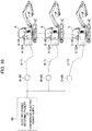
- FIG. 3 is a hydraulic circuit diagram depicting a configuration of a hydraulic drive system included in the above-described electrically driven hydraulic excavator. Incidentally, FIG. 3 depicts, as a representative, a configuration related to the left travelling hydraulic motor 13A and the boom hydraulic cylinder 19.
- the hydraulic drive system includes: an electric motor 31; a battery device 7 as a power source of the electric motor 31; an inverter 32 that drives the electric motor 31 by controlling an electric power supplied to the electric motor 31; a hydraulic pump 33 and a pilot pump 34 driven by the electric motor 31; the above-described plurality of hydraulic actuators 13A, 19, ... (hydraulic actuators other than the left travelling hydraulic motor 13A and the boom hydraulic cylinder 19 are not depicted) driven by a pressurized fluid delivered from the hydraulic pump 33; a plurality of directional control valves 36, 38, ...
- the left travelling operation device 35 has the left travelling control lever 23A.
- the flow of the pressurized fluid from the hydraulic pump 33 to the left travelling hydraulic motor 13A is controlled according to an operation in the forward-rearward direction of the control lever 23A.
- the bucket and boom operation device 37 has the boom and bucket control lever 24B.
- the flow of the pressurized fluid from the hydraulic pump 33 to the boom hydraulic cylinder 19 is controlled according to an operation in the forward-rearward direction of the control lever 24B.
- Pressure sensors 26A and 26B that detect pilot pressures (operation signals) generated by a plurality of pilot valves included in the operation device 35 are provided to a hydraulic line between the hydraulic pilot type operation device 35 and the left travelling directional control valve 36.
- pressure sensors 26C and 26D that detect pilot pressures (operation signals) generated by a plurality of pilot valves included in the operation device 37 are provided to a hydraulic line between the operation device 37 and the boom directional control valve 38. Detection signals of the pressure sensors 26A and 26B and the pressure sensors 26A and 26B are input to a controller 53 (see FIG. 4 to be described later).
- configurations of the hydraulic drive system which configurations are related to the right travelling hydraulic motor 13B, the arm hydraulic cylinder 20, the bucket hydraulic cylinder 21, the swing hydraulic motor, the swing hydraulic cylinder, and the blade hydraulic cylinder not depicted in FIG. 3 are substantially similar.
- the left travelling directional control valve 36 and the boom directional control valve 38 and the other directional control valves not depicted are of a center bypass type, and each have a center bypass passage located on a center bypass line 39.
- the center bypass passage of each directional control valve is connected in series with the center bypass line 39.
- the center bypass passage communicates when a spool of each directional control valve is at a neutral position.
- the center bypass passage is interrupted when the spool of each directional control valve is switched to a switching position in the left side or the right side in FIG. 3 .
- An upstream side of the center bypass line 39 is connected to a delivery line 40 of the hydraulic pump 33.
- a downstream side of the center bypass line 39 is connected to a tank line 41.
- a pressure sensor 25 for detecting the pressure of the delivery line 40 (delivery pressure of the hydraulic pump 33) is provided to the delivery line 40 of the hydraulic pump 33.
- a detection signal of the pressure sensor 25 is input to the controller 53 (see FIG. 4 to be described later).
- the left travelling directional control valve 36 is configured to be switched by a pilot pressure from the operation device 35.
- the operation device 35 has the above-described left travelling control lever 23A and a pair of pilot valves (not depicted) that generate a pilot pressure with the delivery pressure of the pilot pump 34 as a source pressure according to an operation in the forward-rearward direction of the control lever 23A.
- a pilot pressure generated by one pilot valve according to an amount of the operation is output to a pressure receiving portion in the right side, in FIG. 3 , of the left travelling directional control valve 36, and the left travelling directional control valve 36 is thereby switched to the switching position in the right side in FIG. 3 .
- the left travelling hydraulic motor 13A rotates in a forward direction, and the driving wheel 10 and the crawler 12 on the left rotate in the forward direction.
- a pilot pressure generated by the other pilot valve is output to a pressure receiving portion in the left side, in FIG. 3 , of the left travelling directional control valve 36 according to an amount of the operation, and the left travelling directional control valve 36 is thereby switched to the switching position in the left side in FIG. 3 . Consequently, the left travelling hydraulic motor 13A rotates in a rearward direction, and the driving wheel 10 and the crawler 12 on the left rotate in the rearward direction.
- the pilot pressures generated by the pilot valves of the operation device 35 are increased in proportion to the operation amount.
- the operation amount of the operation device 35 and the switching direction of the left travelling directional control valve 36 can be measured on the basis of the detection values of the pressure sensors 26A and 26B.
- the boom directional control valve 38 is configured to be switched by a pilot pressure from the operation device 37.
- the operation device 37 has the boom and bucket control lever 24B and a pair of pilot valves not depicted or the like that generate a pilot pressure with the delivery pressure of the pilot pump 34 as a source pressure according to an operation in the forward-rearward direction of the control lever 24B.
- a pilot pressure generated by one pilot valve according to an amount of the operation is output to a pressure receiving portion in the right side, in FIG. 3 , of the boom directional control valve 38, and the boom directional control valve 38 is thereby switched to the switching position in the right side in FIG. 3 .
- the pilot pressures generated by the pilot valves within the operation device 37 are increased in proportion to the operation amount.
- the operation amount of the operation device 37 and the switching direction of the boom directional control valve 38 can be measured from the detection values of the pressure sensors 26C and 26D.
- a delivery line 43 of the pilot pump 34 is provided with a pilot relief valve (not depicted) that holds the delivery pressure of the pilot pump 34 constant.
- the delivery line 43 of the pilot pump 34 is also provided with a lock valve 45.
- the lock valve 45 is configured to be switched according to an operation of the above-described gate lock lever.
- a lock switch 47 (see FIG. 4 to be described later) is provided which is set in a closed state when the gate lock lever is in the lock release position (lowered position), and is set in an opened state when the gate lock lever is in the lock position (raised position).
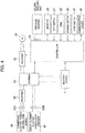
- FIG. 4 is a block diagram depicting a configuration of an electric system in one embodiment of the present invention.
- the electric system in the present embodiment has a function of supplying and charging the battery device 7 with an electric power supplied from a distribution board 48 (hereinafter referred to as a commercial electric power distribution board as appropriate) connected to an electric power receiving facility 80 (see FIG. 10 ) of a commercial electric power supply or a direct-current power rapid charger 49 and a function of operating the electrically driven hydraulic excavator by supplying electric power from the commercial electric power distribution board 48 or the battery device 7 to the electric motor 31 through the inverter 32.
- a distribution board 48 hereinafter referred to as a commercial electric power distribution board as appropriate
- an electric power receiving facility 80 see FIG. 10
- the electric system includes the monitor 30, a communication device 46, and the controller 53.
- the controller 53 is supplied with signals from the pressure sensor 25, the pressure sensors 26A and 26B, and the pressure sensors 26A and 26B, and is supplied with signals from the key switch 27, the dial 28, the charge switch 29, and the lock switch 47.
- the monitor 30 displays an action state, a state of charge (SOC) indicating a remaining capacity of the battery device 7, a present time, or the like according to input from the controller 53.
- the monitor 30 has input means such as a switch operable by a worker. By operating the input means, it is possible to send various information to the controller 53, and set necessary information in the controller 53.
- the controller 53 is also connected to the communication device 46.
- the communication device 46 is a short-range wireless communication module (wireless communication device).
- the communication device 46 serves as means for communicating with other electrically driven hydraulic excavators (here, the other electrically driven hydraulic excavators similarly include a communication device 46) connected to a same network.
- the controller 53 receives data from the other electrically driven hydraulic excavators and transmit data to the other electrically driven hydraulic excavators through the communication device 46.
- controller 53 is connected to a battery controller 59 within the battery device 7 to be described later, and monitors a battery state within the battery device 7 (see FIG. 6 to be described later).
- the inverter 32 controls a voltage applied to the electric motor 31 (more specifically, the frequency of the supplied voltage) and thereby controls the revolution speed of the electric motor 31 according to a revolution speed control command from the controller 53.
- controller 53 switches between connection and interruption of relays 54A and 54B within a changer 51 (see FIG. 5 to be described later), and thereby controls the supply of power.
- FIG. 5 is a diagram depicting a configuration of the changer 51 together with related apparatuses.
- Alternating-current power supplied from the commercial electric power distribution board 48 through a power receiving connector 52A is converted into a direct current in a rectifier 50.
- the direct current is supplied to the changer 51.
- Direct-current power supplied from the direct-current power rapid charger 49 through a power receiving connector 52B is supplied to the changer 51 as it is.
- the changer 51 has the relays 54A and 54B.
- the rectifier 50 is connected to the relay 54A.
- the power receiving connector 52B is connected to the relay 54B.
- the controller 53 turns the relay 54A on, and turns the relay 54B off, so that the electric power from the commercial electric power distribution board 48, that is, the direct-current power converted from an alternating current by the rectifier 50 is supplied to a high voltage circuit.
- the direct-current electric power from the direct-current power rapid charger 49 is supplied to the high voltage circuit by turning the relay 54A off, and turning the relay 54B on.
- the battery device 7 is connected to the high voltage circuit within the changer 51.
- FIG. 6 is a diagram depicting a configuration of the battery device 7.
- the battery device 7 includes a battery module 62 formed by connecting a plurality of battery cells 62A, 62B, ... in series with each other and the battery controller 59.
- the battery cells 62A, 62B, ... are monitored and controlled by a cell controller (not depicted) provided within the battery module 62.
- the battery controller 59 is supplied with a state quantity such as a cell voltage, or a cell temperature detected by the cell controller, and periodically transmits the state quantity to the controller 53.
- a current sensor 63 is provided in a positive electrode side of the battery module 62.
- the current sensor 63 detects an input-output current value of the battery device 7.
- the input-output current value is transmitted to the controller 53 through the battery controller 59.
- the controller 53 computes the temperature of the battery device, a total voltage, an SOC, and a supplied electric power from the information received from the battery controller 59.
- the controller 53 turns a relay 64 off, and thereby interrupts connection between the battery device 7 and the circuit.
- the computed SOC of the battery device 7 is displayed on the monitor 30 according to a display signal from the controller 53.
- the key switch 27 is formed by a key cylinder and a key that can be inserted into the key cylinder.
- the key switch 27 is configured to output a signal according to a rotational operation position (an OFF position, an ON position, or a START position) of the key.
- the dial 28 gives an instruction for a target revolution speed of the electric motor 31, and is configured to output a signal of the target revolution speed corresponding to the rotational operation position.
- the charge switch 29 gives an instruction for turning battery charge control on or off, and is configured to output a signal corresponding to an operation position thereof (an OFF position or an ON position).
- the electrically driven hydraulic excavator according to the present embodiment has two action states, that is, an operational state and a charging state.
- FIG. 7 is a table depicting the action states and action conditions of the electrically driven hydraulic excavator according to the present embodiment.
- a state in which power is supplied to the inverter 32, and the electric motor 31 and the hydraulic pump 33 are rotating will be referred to as an operation mode.
- a state in which power is supplied to the battery device 7, and the electric motor 31 is stopped, on the other hand, will be referred to as a charge mode.
- the charge mode and the operation mode will be described in the following.
- the controller 53 performs battery charge control when the controller 53 determines that the key switch 27 is at the OFF position on the basis of the voltage value of a signal from the key switch 27, the controller 53 determines that the charge switch 29 is operated to the ON position on the basis of the voltage value of a signal from the charge switch 29, and the controller 53 determines that a cable from the commercial electric power distribution board 48 or the direct-current power rapid charger 49 is connected through the power receiving connector 52A or 52B on the basis of the voltage value of a signal from a cable connection detecting circuit (not depicted).
- the controller 53 When the commercial electric power distribution board 48 is connected, the controller 53 performs control so as to set the relay 54A within the changer 51 in a closed state, and set the relay 54B within the changer 51 in an opened state. In addition, when the direct-current power rapid charger 49 is connected, the controller 53 performs control so as to set the relay 54A within the changer 51 in an opened state, and set the relay 54B within the changer 51 in a closed state. Direct-current power is supplied from the relay 54A or the relay 54B in a closed state to the battery device 7 through the high voltage circuit.
- each of the relays 54A and 54B is controlled to an opened state for safety.
- the controller 53 stops charging by controlling the relay 54A and the relay 54B to an opened state when the controller 53 determines that the charge switch 29 is operated to the OFF position on the basis of the voltage value of a signal from the charge switch 29 during charging of the battery device 7.
- the SOC of the battery device 7 exceeds a predetermined threshold value, it is determined that the battery is fully charged, and the charging is stopped by similarly controlling the relay 54A and the relay 54B to an opened state.
- the operation mode using the battery device 7 will be described.
- the controller 53 is, for example, configured to start driving the electric motor 31 by an electric power from the battery device 7 when the controller 53 determines that the key switch 27 is operated to the START position on the basis of the voltage value of a signal from the key switch 27, the controller 53 determines that the charge switch 29 is operated to the OFF position on the basis of the voltage value of a signal from the charge switch 29, and the controller 53 determines that cables from the commercial electric power distribution board 48 and the direct-current power rapid charger 49 are not connected through the power receiving connector 52A or 52B on the basis of the voltage value of a signal from the cable connection detecting circuit (not depicted).
- the driving of the electric motor 31 by the electric power from the battery device 7 may be started when it is further determined that the gate lock lever is at the lock release position on the basis of the voltage value of a signal from the lock switch 47.
- the controller 53 performs control in a direction of setting the relays 54A and 54B within the changer 51 in an opened state, and thus interrupting circuit connection to the commercial electric power distribution board 48 and the direct-current power rapid charger 49.
- the controller 53 outputs a command of the target revolution speed indicated by the dial 28 to the inverter 32.
- the inverter 32 is configured to control a voltage applied to the electric motor 31 in response to this command so that an actual revolution speed of the electric motor 31 becomes the target revolution speed.
- the controller 53 for example, outputs a stop command to the inverter 32 when the controller 53 determines that the key switch 27 is operated to the OFF position on the basis of the voltage value of a signal from the key switch 27 during the driving of the electric motor 31.
- the inverter 32 is configured to stop the electric motor 31 in response to this command.
- the controller 53 determines that the remaining battery capacity is decreased, and outputs an output limiting command to the inverter 32.
- the inverter 32 is configured to control the revolution speed of the electric motor 31 according to this command, and ultimately stop the electric motor 31 when the SOC falls below an SOC threshold value at which it is determined that there is a safety problem.
- the controller 53 is, for example, configured to start driving the electric motor 31 by an electric power from the commercial electric power distribution board 48 when the controller 53 determines that the key switch 27 is operated to the START position on the basis of the voltage value of a signal from the key switch 27, the controller 53 determines that the charge switch 29 is operated to the OFF position on the basis of the voltage value of a signal from the charge switch 29, and the controller 53 determines that the cable from the commercial electric power distribution board 48 is connected but the cable from the direct-current power rapid charger 49 is not connected through the power receiving connector 52A or 52B on the basis of the voltage value of a signal from the cable connection detecting circuit (not depicted).
- the driving of the electric motor 31 by the electric power from the commercial electric power distribution board 48 may be started when it is further determined that the gate lock lever is at the lock release position on the basis of the voltage value of a signal from the lock switch 47.
- the controller 53 performs control in a direction of connecting the commercial electric power distribution board 48 to the high voltage circuit and supplying electric power to the high voltage circuit by switching the relay 54A within the changer 51 to a closed state and switching 54B within the changer 51 to an opened state, and interrupting circuit connection to the direct-current power rapid charger 49.
- the controller 53 computes a revolution speed control command Nd on the basis of the target revolution speed indicated by the dial 28 and a motor demanded revolution speed Ndr to be described later.
- the controller 53 controls a voltage applied to the electric motor 31 by outputting the revolution speed control command Nd to the inverter 32.
- the controller 53 thereby controls the revolution speed of the electric motor 31.
- the controller 53 for example, outputs a stop command to the inverter 32 when the controller 53 determines that the key switch 27 is operated to the OFF position on the basis of the voltage value of a signal from the key switch 27 during the driving of the electric motor 31.
- the inverter 32 is configured to stop the electric motor 31 in response to this command.
- FIG. 8 is a functional block diagram depicting processing functions of the controller 53 when control of driving the electric motor 31 in a commercial electric power driving mode is performed.
- the electrically driven hydraulic excavator according to the present embodiment can supply power to the electric motor 31 from the electric power receiving facility 80 (see FIG. 10 ) of the commercial electric power supply through the distribution board 48. Therefore, the electrically driven hydraulic excavator according to the present embodiment includes a commercial electric power driving control system.
- the commercial electric power driving control system includes: the communication device 46 that transmits and receives data to and from other electrically driven construction machines sharing the electric power receiving facility; and the controller 53.
- the controller 53 has functions of computing an own demanded power Pd1 for driving the plurality of hydraulic actuators 13A, 19, ...
- the controller 53 calculates an allowable power Plim as a power limit value usable by the electric motor 31 on the basis of the own demanded power Pd1, the demanded powers Pd2, Pd3, ..., Pdn of the other electrically driven construction machines received through the communication device 46, and an allowable electric power of the electric power receiving facility 80 (see FIG. 10 ) of the commercial electric power supply, and controls the electric motor 31 such that a power consumption of the electric motor 31 does not exceed the allowable power Plim.
- the controller 53 includes a demanded power computing section 70, an internal setting recording section 71, an allowable power computing section 72, a minimum value selecting section 73, and a motor revolution speed computing section 75.
- the demanded power computing section 70 is supplied with signals from the pressure sensors 26A and 26B detecting the pilot pressures generated by the pilot valves of the operation device 35 and the pressure sensors 26C and 26D detecting the pilot pressures generated by the pilot valves of the operation device 37 and signals from pressure sensors detecting the pilot pressures generated by the pilot valves of other operation devices not depicted, and computes the own demanded power Pd1 for driving the hydraulic actuators 13A, 19, ... on the basis of the pilot pressures indicated by those signals.
- the demanded power Pd1 is sent to the allowable power computing section 72 and the minimum value selecting section 73.
- the demanded power Pd1 is also sent to the communication device 46 connected to the controller 53, and is transmitted to the other electrically driven hydraulic excavators through the communication device 46.
- the operation devices may, for example, be of an electric type.
- the operation signals are electric signals
- the demanded power computing section 70 may compute the own demanded power Pd1 directly using the electric signals input to the controller 53.
- the demanded power computing section 70 may be supplied with the detection signal of the pressure sensor 25 in addition to the operation signals, and compute the own demanded power Pd1 on the basis of the operation signals and the delivery pressure of the hydraulic pump 33.
- the internal setting recording section 71 is supplied with setting information from the monitor 30, and records the setting information therein.
- the worker inputs the allowable electric power of the electric power receiving facility 80 (see FIG. 10 ) of the commercial electric power supply, the allowable electric power being determined in advance on the basis of an electric power contracted with an electric power supplier, by operating a switch provided to the monitor 30 or the like.
- the monitor 30 outputs the allowable electric power to the internal setting recording section 71.
- the internal setting recording section 71 computes an electric power supply allowable power PSlim of the electric power receiving facility 80 by multiplying the allowable electric power by a power conversion coefficient, and records the electric power supply allowable power PSlim as setting information.
- the calculation of obtaining the electric power supply allowable power PSlim from the allowable electric power of the electric power receiving facility 80 of the commercial electric power supply may be performed in the monitor 30.
- the allowable power computing section 72 is supplied with the own demanded power Pd1 computed in the demanded power computing section 70, the electric power supply allowable power PSlim recorded in the internal setting recording section 71, and the demanded powers Pd2, Pd3, ..., Pdn from the other electrically driven hydraulic excavators, the demanded powers Pd2, Pd3, ..., Pdn being received by the communication device 46, and computes the allowable power Plim of the electric motor 31 usable by the own machine body.
- the other electrically driven hydraulic excavators that transmit and receive data by the communication devices 46 also have a controller similar to the controller 53 depicted in FIG. 8 .
- the demanded power computing sections of these controllers compute the demanded powers Pd2, Pd3, ..., Pdn of the respective machine bodies.
- the demanded power Pd1 computed in the demanded power computing section 70 depicted in FIG. 8 may be referred to as own demanded power as appropriate to be distinguished from these demanded powers Pd2, Pd3, ...., Pdn.
- the demanded power Pd1 computed by the demanded power computing section 70 and the allowable power Plim computed by the allowable power computing section 72 are guided to the minimum value selecting section 73.
- the minimum value selecting section 73 selects the value of the lower of the allowable power Plim and the demanded power Pd1 as a target demanded power Pr.
- the motor revolution speed computing section 75 is supplied with the target demanded power Pr and a signal from the pressure sensor 25 that detects a pressure P of the delivery line 40 of the hydraulic pump 33, and computes a motor demanded revolution speed Ndr on the basis of the target demanded power Pr and the pressure P.
- a target revolution speed computation table 74 is supplied with an indication signal corresponding to the rotational operation position from the dial 28, and computes a target revolution speed Nd0 of the electric motor 31 according to the indication signal of the dial 28.
- Set in the target revolution speed computation table 74 are characteristics of the target revolution speed corresponding to the indication signal (rotational operation position) of the dial 28.
- the motor demanded revolution speed Ndr of the motor revolution speed computing section 75 and the target revolution speed Nd0 computed in the target revolution speed computation table 74 are input to a minimum value selecting section 76.
- the minimum value selecting section 76 selects, as a revolution speed control command Nd, the value of the lower of the motor demanded revolution speed Ndr and the target revolution speed Nd0.
- the revolution speed control command Nd is output to the inverter 32.
- the inverter 32 controls the voltage applied to the electric motor 31 according to the revolution speed control command Nd, and thereby controls the revolution speed of the electric motor 31 so that the actual revolution speed of the electric motor 31 becomes the revolution speed control command Nd.
- FIG. 9 is a functional block diagram depicting processing functions of the demanded power computing section 70.
- the demanded power computing section 70 includes tables 77A, 77B, 77C, and 77D and a maximum value selecting section 78.
- the tables 77A, 77B, 77C, and 77D are respectively supplied with signals from the pressure sensors 26A, 26B, 26C, and 26D, and compute demanded powers Pd_a, Pd_b, Pd_c, and Pd_d.
- Set in the tables 77A, 77B, 77C, and 77D are characteristics of respective demanded powers corresponding to operation amounts of the control levers of the operation devices 35 and 37 that determine demanded actuation amounts of the hydraulic actuators 13A, 19, ... (the pilot pressures Pi_a, Pi_b, Pi_c, and Pi_d detected by the pressure sensors 26A, 26B, 26C, and 26D).
- the demanded powers Pd_a, Pd_b, Pd_c, and Pd_d corresponding to the operation amounts of the control levers are computed by referring to the pilot pressures Pi_a, Pi_b, Pi_c, and Pi_d detected by the pressure sensors 26A, 26B, 26C, and 26D in the tables 77A, 77B, 77C, and 77D. Characteristics of the demanded powers set in the tables 77A, 77B, 77C, and 77D are determined in advance for respective specifications of the machine body.
- the demanded powers Pd_a, Pd_b, Pd_c, and Pd_d computed in the tables 77A, 77B, 77C, and 77D are guided to the maximum value selecting section 78.
- a largest value of the demanded powers Pd_a, Pd_b, Pd_c, and Pd_d is selected and output as the demanded power Pd1.
- the controller 53 computes the own demanded power Pd1 in the demanded power computing section 70 on the basis of the pilot pressures Pi_a, Pi_b, Pi_c, and Pi_d detected by the plurality of pressure sensors 26A, 26B, 26C, and 26D.
- the demanded power computing section 70 may include an adding section in place of the maximum value selecting section 78, and compute the demanded power Pd1 by adding together the demanded powers Pd_a, Pd_b, Pd_c, and Pd_d.
- a first term on a right side is the electric power supply allowable power PSlim set in the internal setting recording section 71.
- a denominator is a sum of the demanded powers Pd1, Pd2, Pd3, ..., Pdn (total demanded power) of the electrically driven hydraulic excavators operating with the electric power supplied from the electric power receiving facility 80 of the same commercial electric power supply.
- the demanded powers Pd1, Pd2, Pd3, ..., Pdn are values calculated in the demanded power computing sections 70 of the controllers 53 included in the respective machine bodies of the electrically driven hydraulic excavators, and are included in data received by the communication device 46 included in each machine body.
- a numerator is the own demanded power Pd1 demanded by the electrically driven hydraulic excavator according to the present embodiment described above.
- the second term represents a ratio of the power (own demanded power) Pd1 demanded by the machine body in question to the total demanded power of the electrically driven hydraulic excavators operating with the electric power supplied from the same electric power receiving facility 80 of the commercial electric power supply.
- a result of distributing the electric power supply allowable power PSlim that can be output by the allowable electric power of the electric power receiving facility 80 of the commercial electric power supply according to the ratio of the demanded power of the electrically driven hydraulic excavator using the electric power receiving facility 80 is the allowable power Plim.
- the controller 53 computes the ratio of the own demanded power Pd1 to the total demanded power of the own demanded power Pd1 and the demanded powers Pd2, Pd3, ..., Pdn of the other electrically driven construction machines, the demanded powers Pd2, Pd3, ..., Pdn being received through the communication device 46, and computes the allowable power Plim on the basis of the allowable electric power of the electric power receiving facility 80 of the commercial electric power supply and the above-described ratio.
- the controller 53 sets the electric power supply allowable power PSlim computed on the basis of the allowable electric power of the electric power receiving facility 80 of the commercial electric power supply in the internal setting recording section 71 in advance, and computes the allowable power Plim by multiplying the electric power supply allowable power PSlim by the ratio of the own demanded power Pd1.
- the motor revolution speed computing section 75 calculates a demanded revolution speed Ndr by Equation (2) depicted below.
- Ndr 60 ⁇ 10 3 ⁇ Pr P ⁇ ⁇ m ⁇ qm
- Equation (2) ⁇ m in a denominator of a third term denotes mechanical efficiency of the hydraulic pump 33, and qm denotes a capacity of the hydraulic pump 33, that is, an amount of oil delivered per rotation of the hydraulic pump.
- the demanded revolution speed Ndr is limited between a minimum revolution speed Nmin and a maximum revolution speed Nmax determined by specifications of the electric motor 31.
- Equation (2) Pr as a numerator of the third term is the target demanded power in which the allowable electric power of the electric power receiving facility 80 (see FIG. 10 ) of the commercial electric power supply is taken into consideration, the target demanded power being selected as the value of the lower of the own demanded power Pd1 and the allowable power Plim in the minimum value selecting section 73.
- the demanded revolution speed Ndr is computed on the basis of the target demanded power Pr and the present pressure of the hydraulic pump 33, that is, the detected value P of the pressure sensor 25.
- the controller 53 selects the value of the smaller of the own demanded power Pd1 and the allowable power Plim as the target demanded power Pr in the minimum value selecting section 73, computes the demanded revolution speed Ndr of the electric motor 31 in the motor revolution speed computing section 75 on the basis of the target demanded power Pr, and controls the revolution speed of the electric motor 31 on the basis of the demanded revolution speed Ndr.
- FIG. 10 is a general configuration diagram related to operation of a plurality of electrically driven hydraulic excavators that operate with an electric power supplied from the same electric power receiving facility 80 of the commercial electric power supply.
- a feed cable A-71 is connected to a power receiving connector A-52A provided to an electrically driven hydraulic excavator A, and is supplied with power of a commercial electric power supply from a distribution board A-48.
- a feed cable B-71 is connected to a power receiving connector B-52A provided to an electrically driven hydraulic excavator B, and is supplied with the power of the commercial electric power supply from a distribution board B-48.
- a feed cable C-71 is connected to a power receiving connector C-52A provided to an electrically driven hydraulic excavator C, and is supplied with the power of the commercial electric power supply from a distribution board C-48.
- the distribution boards A-48, B-48 and C-48 are connected in parallel to the electric power receiving facility 80 of the commercial electric power supply, and is supplied with the power of the commercial electric power supply from the electric power receiving facility 80.
- a communication device A-46 included in the electrically driven hydraulic excavator A, a communication device B-46 included in the electrically driven hydraulic excavator B, and a communication device C-46 included in the electrically driven hydraulic excavator C form a wireless network, and mutually transmit and receive data input from controllers (depicted in FIG. 4 ).
- each machine body is operating in the commercial electric power operation mode, that is, operating with the electric power supplied from the same electric power receiving facility 80 of the commercial electric power supply.
- the electric power supply allowable power PSlim determined in consideration of an amount of conversion from the supplied power to the power of the electrically driven hydraulic excavator so as not to exceed the allowable electric power of the electric power receiving facility 80 is set in the internal setting recording section 71 (depicted in FIG. 8 ) of each machine body.
- the electric power supply allowable power PSlim is computed when the worker inputs the contracted electric power set in the electric power receiving facility 80 of the commercial electric power supply to the monitor 30 provided to each machine body as described above.
- the demanded power of the electrically driven hydraulic excavator A is Pd1
- the demanded power of the electrically driven hydraulic excavator B is Pd2
- the demanded power of the electrically driven hydraulic excavator C is Pd3.
- the demanded power Pd1 is sent as data to the electrically driven hydraulic excavator B and the electrically driven hydraulic excavator C through the communication device A-46.
- the demanded power Pd2 is sent to the electrically driven hydraulic excavator A and the electrically driven hydraulic excavator C through the communication device B-46
- the demanded power Pd3 is sent to the electrically driven hydraulic excavator A and the electrically driven hydraulic excavator B through the communication device C-46.
- the allowable power computing section 72 of the electrically driven hydraulic excavator A computes an allowable power Plim (A) by Equation (3) depicted below.
- Plim A PSlim ⁇ Pd 1 Pd 1 + Pd 2 + Pd 3
- the target demanded power Pr as the output of the minimum value selecting section 73 is Pd1.
- Equation (4) the allowable power Plim (B) computed by the electrically driven hydraulic excavator B and the allowable power Plim (C) computed by the electrically driven hydraulic excavator C are computed by Equation (4) depicted below.
- Plim B PSlim ⁇ Pd 2 Pd 1 + Pd 2 + Pd 3
- Plim C PSlim ⁇ Pd 3 Pd 1 + Pd 2 + Pd 3
- the target demanded powers Pr as outputs of the minimum value selecting sections 73 of the electrically driven hydraulic excavators B and C are Pd2 and Pd3, respectively.
- the motor demanded revolution speeds Ndr are determined by the demanded powers Pd1, Pd2, and Pd3, and are not limited by the allowable power Plim.
- operation is not limited by the allowable power Plim, but is performed at a demanded revolution speed corresponding to the demanded power.
- the target demanded power Pr as the output of the minimum value selecting section 73 is Plim (A).
- the target demanded powers Pr as the outputs of the minimum value selecting sections 73 are Plim (B) and Plim (C), respectively.
- the motor demanded revolution speeds Ndr are determined by the allowable powers Plim (A), Plim (B), and Plim (C), and are limited by the allowable power Plim.
- the sum of the allowable powers of the respective electrically driven hydraulic excavators is limited to the electric power supply allowable power PSlim. A situation is thus avoided in which a sum of the powers supplied to the respective machine bodies exceeds the allowable electric power of the electric power receiving facility 80 of the commercial electric power supply.
- the present embodiment in a case where a plurality of electrically driven construction machines operate simultaneously, it is possible to avoid exceeding the allowable electric power that can be output by the electric power receiving facility 80 of the commercial electric power supply as an external electric power supply while distributing supplied electric power without a work imbalance between different machine bodies according to the respective demanded powers Pd1, Pd2, Pd3, ..., Pdn of the plurality of electrically driven construction machines thereby make it possible to perform work efficiently within the allowable electric power of the electric power receiving facility 80.
- the electrically driven construction machine may be a construction machine other than a hydraulic excavator,, for example, another construction machine such as a hydraulic excavator of a wheel type, or a wheel loader.
Landscapes
- Engineering & Computer Science (AREA)
- Power Engineering (AREA)
- Civil Engineering (AREA)
- Structural Engineering (AREA)
- General Engineering & Computer Science (AREA)
- Mining & Mineral Resources (AREA)
- Transportation (AREA)
- Mechanical Engineering (AREA)
- Life Sciences & Earth Sciences (AREA)
- Sustainable Energy (AREA)
- Sustainable Development (AREA)
- Physics & Mathematics (AREA)
- Fluid Mechanics (AREA)
- Operation Control Of Excavators (AREA)
- Remote Monitoring And Control Of Power-Distribution Networks (AREA)
- Supply And Distribution Of Alternating Current (AREA)
Abstract
Description
- The present invention relates to an electrically driven construction machine such as a hydraulic excavator, for example, and particularly to an electrically driven construction machine that drives a hydraulic pump by using, as a power source, an electric motor driven by electric power supplied from an external electric power supply device.
- Many of construction machines typified by hydraulic excavators perform work by using a diesel engine as a power source, and operating hydraulic actuators by a pressurized fluid fed from a hydraulic pump coupled to the diesel engine.
- There is a problem in that the exhaust gas of the diesel engine generally includes particulate matter (PM) and nitrogen oxide (NOx) in large quantities as compared with an engine using another fuel such as gasoline as a power source.
- Accordingly, rapid progress in setting statutory regulations is being made worldwide to reduce the above-described substances included in the exhaust gas of the diesel engine stepwise.
- From such a background, there is a possibility that many construction machines operating on work sites may henceforth make a transition to electrically driven construction machines that use electricity as a power source, and do not generate the exhaust gas.
- Under such a background,
Patent Document 1 describes a technology related to a charging device that calculates and controls a threshold value of an output current such that electric power at a time of charging supplied to an electrically driven construction machine mounting a battery does not exceed an allowable electric power based on an electric power contracted with an electric power supplier. This charging device is provided with means for inputting electric power specifications (corresponding to contracted electric power in the present specification) set in an electric power receiving apparatus (corresponding to an electric power receiving facility of a commercial electric power supply in the present specification). - Patent Document 1:
JP-2010-206978-A - Some electrically driven construction machines such as hydraulic excavators operate by driving an electric motor by electric power supplied to a machine body from an electric power distribution board provided on a work site through a feed cable, and actuating a hydraulic pump.
- In a case where a plurality of such electrically driven construction machines are operated on one work site, the electric power distribution boards are provided in operation ranges of the respective electrically driven construction machines, and each distribution board is supplied with electric power from an electric power receiving facility (external electric power supply) of a commercial electric power supply, the electric power receiving facility being installed in the vicinity of the work site (within the premises of a factory or the like).
- In general, the electric power receiving facility of the commercial electric power supply is installed within the premises of a factory or the like, and transforms the electric power of the commercial electric power supply in the electric utility side and supplies the transformed power to the distribution boards at respective places within the work site. When power consumption within the work site increases, and the electric power supplied from the electric power receiving facility exceeds the electric power contracted with the electric power supplier, an excess charge, interruption of a load, or the like may occur.
- Therefore, in a case where the plurality of electrically driven construction machines are operated within the work site using the same electric power receiving facility, it is necessary to provide means for limiting a total value of electric powers supplied to the respective electrically driven construction machines through the distribution boards to an allowable electric power value or lower so as not to exceed the contracted electric power, and efficiently distributing and supplying the electric power to the plurality of electrically driven construction machines.
- The above-described
Patent Document 1 is a technology related to the charging of an electrically driven construction machine mounted with a battery. However, the technology can operate a plurality of electrically driven construction machines by a configuration in which the charging device is replaced with the electric power distribution board. When such a configuration is considered,Patent Document 1 has the following problems. - The threshold value of an output current in
Patent Document 1 is only set so that electric power supplied to one electrically driven construction machine does not exceed the allowable electric power of the electric power receiving facility (electric power receiving apparatus), and a limitation value corresponding to the demanded power of each electrically driven construction machine in the case where the plurality of electrically driven construction machines operate is not considered. The electrically driven construction machines differ in terms of machine body specifications, work contents, the state of the work site, a load state such as an operation rate per work time. Thus, the power demanded by each machine body differs. - Therefore, when appropriate electric power supply limitation according to the powers demanded by the machine bodies is not performed, a problem, for example, an imbalance in work speed between different machine bodies, a stop of a high-load machine body, or the like occurs.
- The present invention has been made in view of the problems of the above-described conventional technology. It is an object of the present invention to provide an electrically driven construction machine in which, in a case where a plurality of electrically driven construction machines operate simultaneously, it is possible to avoid exceeding the allowable electric power that can be output by the electric power receiving facility of a commercial electric power supply as an external electric power supply while distributing supplied electric power without a work imbalance between different machine bodies according to the respective demanded powers of the plurality of electrically driven construction machines thereby make it possible to perform work efficiently within an allowable electric power of the electric power receiving facility.
- In order to achieve the above-described object, according to the present invention, there is provided an electrically driven construction machine comprising: an electric motor; a hydraulic pump driven by the electric motor; a plurality of hydraulic actuators driven by a pressurized fluid delivered from the hydraulic pump; a plurality of directional control valves that control flows of the pressurized fluid supplied from the hydraulic pump to the plurality of hydraulic actuators; and a plurality of operation devices that generate operation signals for instructing operation of the plurality of hydraulic actuators and switching the plurality of directional control valves, the electric motor being driven by an electric power from an electric power receiving facility; wherein the electrically driven construction machine further comprises: a communication device that transmits and receives data to and from other electrically driven construction machines sharing the electric power receiving facility; and a controller configured to compute an own demanded power for driving the plurality of hydraulic actuators on a basis of the operation signals of the plurality of operation devices, transmit the own demanded power to the other electrically driven construction machines through the communication device, and receive demanded powers computed in the other electrically driven construction machines through the communication device, and wherein the controller is further configured to compute an allowable power usable by the electric motor on a basis of the own demanded power, demanded powers of the other electrically driven construction machines received through the communication device, and an allowable electric power of the electric power receiving facility, and control the electric motor such that a power consumption of the electric motor does not exceed the allowable power usable by the electric motor.
- In this way, by computing the own demanded power, transmitting the own demanded power to the other electrically driven construction machines through the communication device, receiving the demanded power computed in the other electrically driven construction machines through the communication device, computing the allowable power usable by the electric motor on the basis of the own demanded power, the demanded power of the other electrically driven construction machine, and the allowable electric power of the electric power receiving facility, and controlling the electric motor such that a power consumption of the electric motor does not exceed the allowable power usable by the electric motor, it is possible to, in a case where a plurality of electrically driven construction machines operate simultaneously, perform work efficiently within an allowable electric power by distributing supplied electric power without a work imbalance between different machine bodies according to the respective demanded powers of the plurality of electrically driven construction machines while avoiding exceeding the allowable electric power that can be output by power receiving facility of a commercial electric power supply.
- According to the present invention, in a case where a plurality of electrically driven construction machines operate simultaneously, it is possible to avoid exceeding the allowable electric power that can be output by the electric power receiving facility of a commercial electric power supply as an external electric power supply while distributing supplied electric power without a work imbalance between different machine bodies according to the respective demanded powers of the plurality of electrically driven construction machines thereby make it possible to perform work efficiently within an allowable electric power of the electric power receiving facility.
-
-
FIG. 1 is a side view depicting a general configuration of an electrically driven hydraulic excavator in one embodiment of the present invention. -
FIG. 2 is a top view of the same electrically driven hydraulic excavator. -
FIG. 3 is a hydraulic circuit diagram depicting a configuration of a hydraulic drive system included in the electrically driven hydraulic excavator. -
FIG. 4 is a block diagram depicting a configuration of an electric system in one embodiment of the present invention. -
FIG. 5 is a diagram depicting a configuration of a changer together with related apparatuses. -
FIG. 6 is a diagram depicting a configuration of a battery device. -
FIG. 7 is a table depicting the action states and action conditions of the electrically driven hydraulic excavator according to the present embodiment. -
FIG. 8 is a functional block diagram depicting processing functions of a controller when control of driving an electric motor in a commercial electric power driving mode is performed. -
FIG. 9 is a functional block diagram depicting processing functions of a demanded power computing section. -
FIG. 10 is a general configuration diagram related to operation of a plurality of electrically driven hydraulic excavators that operate with an electric power supplied from the same electric power receiving facility of a commercial electric power supply. - An embodiment of the present invention will be described with reference to the drawings by taking an electrically driven hydraulic excavator as an example of an application target of the present invention.
-
FIG. 1 is a side view depicting a general configuration of an electrically driven hydraulic excavator in one embodiment of the present invention.FIG. 2 is a top view of the electrically driven hydraulic excavator. Incidentally, in the present specification, a front side (right side inFIG. 1 ), a rear side (left side inFIG. 1 ), a left side (far side facing a paper plane ofFIG. 1 ), and a right side (near side facing the paper plane ofFIG. 1 ) of a driver when the driver is seated in a cab seat of the electrically driven hydraulic excavator in a state depicted inFIG. 1 will be referred to simply as a front side, a rear side, a left side, and a right side. - In
FIG. 1 andFIG. 2 , the electrically driven hydraulic excavator (mini-excavator having an operating mass of less than 6 tons in the present embodiment) includes: a crawler typelower track structure 1; anupper swing structure 2 swingably disposed above thelower track structure 1; a swing frame 3 constituting a lower substructure of theupper swing structure 2; aswing post 4 disposed in the front side of the swing frame 3 so as to be rotatable in a left-right direction; an articulatedwork device 5 coupled to theswing post 4 so as to be rotatable (elevatable) in an upward-downward direction; acanopy type cab 6 provided on the swing frame 3; and a driving batteryunit mounting portion 8 provided in a rear side on the swing frame 3 and housing a battery device 7 (seeFIGS. 4 to 6 to be described later). - The
lower track structure 1 includes: a track frame 9 substantially in the shape of an H as viewed from above; a left and a rightdriving wheel right crawler driving wheels wheels driving wheel 10A (that is, theleft crawler 12A) is rotated by the driving of a left travellinghydraulic motor 13A (seeFIG. 3 to be described later). The rightdriving wheel 10B (that is, theright crawler 12B) is rotated by the driving of a right travellinghydraulic motor 13B. - An
earth moving blade 14 is provided at the front side of the track frame 9 so as to be capable of moving up and down. Theblade 14 is moved up and down by extension and contraction driving of a blade hydraulic cylinder (not depicted). - A
swing wheel 15 is situated in a central portion of the track frame 9. The swing frame 3 is swingably provided through theswing wheel 15. The swing frame 3 (that is, the upper swing structure 2) is swung by the driving of a swing hydraulic motor (not depicted). - The
swing post 4 is provided at the front side of the swing frame 3 so as to be rotatable in the left-right direction. Theswing post 4 is rotated in the left-right direction by expansion and contraction driving of a swing hydraulic cylinder (not depicted). Thework device 5 thereby swings left and right. - The
work device 5 includes aboom 16 coupled to theswing post 4 so as to be rotatable in the upward-downward direction, anarm 17 coupled to theboom 16 so as to be rotatable in the upward-downward direction, and abucket 18 coupled to thearm 17 so as to be rotatable in the upward-downward direction. Theboom 16, thearm 17, and thebucket 18 are rotated in the upward-downward direction by a boomhydraulic cylinder 19, an armhydraulic cylinder 20, and a buckethydraulic cylinder 21. Incidentally, thebucket 18 is replaceable with an attachment (not depicted) incorporating an optional hydraulic actuator, for example. - The
cab 6 is provided with a cab seat (sitting seat) 22 in which the driver is seated. A lefttravelling control lever 23A (seeFIG. 3 to be described later) and a right travelling control lever (not depicted) are provided in front of thecab seat 22, the lefttravelling control lever 23A and the right travelling control lever being operated by hand or foot in forward and rearward directions to instruct operations of the left and right travellinghydraulic motors right crawlers control lever 23A, the optional operating pedal being operated in the left and right directions to instruct operation of an optional hydraulic actuator (that is, operation of an attachment). A swing operating pedal (not depicted) is provided in a foot part further right of the right travelling control lever, the swing operating pedal being operated in the left and right directions to instruct operation of the swing hydraulic cylinder (that is, operation of the swing post 4). - A cross-operated arm and
swing control lever 24A is provided in the left side of thecab seat 22, the arm andswing control lever 24A being operated in the forward and rearward directions to instruct operation of the arm hydraulic cylinder 20 (that is, operation of the arm 17), and being operated in the left and right directions to instruct operation of the swing hydraulic motor (that is, operation of the upper swing structure 2). A cross-operated boom andbucket control lever 24B is provided in the right side of thecab seat 22, the boom andbucket control lever 24B being operated in the forward-rearward direction to instruct operation of the boom hydraulic cylinder 19 (that is, operation of the boom 16), and being operated in the left-right direction to instruct operation of the bucket hydraulic cylinder 21 (that is, operation of the bucket 18). In addition, a blade control lever (not depicted) is provided in the right side of thecab seat 22, the blade control lever being operated in the forward-rearward direction to instruct operation of the blade hydraulic cylinder (that is, operation of the blade 14). - In addition, a gate lock lever (not depicted) is provided in the left side of the cab seat 22 (in other words, a platform of the cab 6), the gate lock lever being operated to a lock release position (specifically a lowered position obstructing the boarding and alighting of the driver) and a lock position (specifically a raised position allowing the boarding and alighting of the driver). In addition, a
key switch 27, adial 28, a charge switch 29 (seeFIG. 4 to be described later), and the like are provided in the right side of thecab seat 22. Furthermore, amonitor 30 is provided in front of the right side of thecab seat 22. -
FIG. 3 is a hydraulic circuit diagram depicting a configuration of a hydraulic drive system included in the above-described electrically driven hydraulic excavator. Incidentally,FIG. 3 depicts, as a representative, a configuration related to the left travellinghydraulic motor 13A and the boomhydraulic cylinder 19. - In
FIG. 3 , the hydraulic drive system includes: anelectric motor 31; abattery device 7 as a power source of theelectric motor 31; aninverter 32 that drives theelectric motor 31 by controlling an electric power supplied to theelectric motor 31; ahydraulic pump 33 and apilot pump 34 driven by theelectric motor 31; the above-described plurality ofhydraulic actuators hydraulic motor 13A and the boomhydraulic cylinder 19 are not depicted) driven by a pressurized fluid delivered from thehydraulic pump 33; a plurality ofdirectional control valves directional control valve 36 and a boomdirectional control valve 38 are not depicted) that control flows of the pressurized fluid supplied from thehydraulic pump 33 to the plurality ofhydraulic actuators type operation devices operation device 35 and a bucket andboom operation device 37 are not depicted) that give instructions for operation of the plurality ofhydraulic actuators directional control valves - The left travelling
operation device 35 has the left travellingcontrol lever 23A. The flow of the pressurized fluid from thehydraulic pump 33 to the left travellinghydraulic motor 13A is controlled according to an operation in the forward-rearward direction of thecontrol lever 23A. The bucket andboom operation device 37 has the boom andbucket control lever 24B. The flow of the pressurized fluid from thehydraulic pump 33 to the boomhydraulic cylinder 19 is controlled according to an operation in the forward-rearward direction of thecontrol lever 24B. -
Pressure sensors operation device 35 are provided to a hydraulic line between the hydraulic pilottype operation device 35 and the left travellingdirectional control valve 36. Similarly,pressure sensors operation device 37 are provided to a hydraulic line between theoperation device 37 and the boomdirectional control valve 38. Detection signals of thepressure sensors pressure sensors FIG. 4 to be described later). - Incidentally, configurations of the hydraulic drive system which configurations are related to the right travelling
hydraulic motor 13B, the armhydraulic cylinder 20, the buckethydraulic cylinder 21, the swing hydraulic motor, the swing hydraulic cylinder, and the blade hydraulic cylinder not depicted inFIG. 3 are substantially similar. - The left travelling
directional control valve 36 and the boomdirectional control valve 38 and the other directional control valves not depicted are of a center bypass type, and each have a center bypass passage located on acenter bypass line 39. The center bypass passage of each directional control valve is connected in series with thecenter bypass line 39. The center bypass passage communicates when a spool of each directional control valve is at a neutral position. The center bypass passage is interrupted when the spool of each directional control valve is switched to a switching position in the left side or the right side inFIG. 3 . An upstream side of thecenter bypass line 39 is connected to adelivery line 40 of thehydraulic pump 33. A downstream side of thecenter bypass line 39 is connected to atank line 41. - In addition, a
pressure sensor 25 for detecting the pressure of the delivery line 40 (delivery pressure of the hydraulic pump 33) is provided to thedelivery line 40 of thehydraulic pump 33. A detection signal of thepressure sensor 25 is input to the controller 53 (seeFIG. 4 to be described later). - The left travelling
directional control valve 36 is configured to be switched by a pilot pressure from theoperation device 35. Theoperation device 35 has the above-described left travellingcontrol lever 23A and a pair of pilot valves (not depicted) that generate a pilot pressure with the delivery pressure of thepilot pump 34 as a source pressure according to an operation in the forward-rearward direction of thecontrol lever 23A. When thecontrol lever 23A is operated, from a neutral position to the front side, for example, a pilot pressure generated by one pilot valve according to an amount of the operation is output to a pressure receiving portion in the right side, inFIG. 3 , of the left travellingdirectional control valve 36, and the left travellingdirectional control valve 36 is thereby switched to the switching position in the right side inFIG. 3 . Consequently, the left travellinghydraulic motor 13A rotates in a forward direction, and the driving wheel 10 and the crawler 12 on the left rotate in the forward direction. On the other hand, when thecontrol lever 23A is operated from the neutral position to the rear side, for example, a pilot pressure generated by the other pilot valve is output to a pressure receiving portion in the left side, inFIG. 3 , of the left travellingdirectional control valve 36 according to an amount of the operation, and the left travellingdirectional control valve 36 is thereby switched to the switching position in the left side inFIG. 3 . Consequently, the left travellinghydraulic motor 13A rotates in a rearward direction, and the driving wheel 10 and the crawler 12 on the left rotate in the rearward direction. - The pilot pressures generated by the pilot valves of the
operation device 35 are increased in proportion to the operation amount. Thus, the operation amount of theoperation device 35 and the switching direction of the left travellingdirectional control valve 36 can be measured on the basis of the detection values of thepressure sensors - The boom
directional control valve 38 is configured to be switched by a pilot pressure from theoperation device 37. Theoperation device 37 has the boom andbucket control lever 24B and a pair of pilot valves not depicted or the like that generate a pilot pressure with the delivery pressure of thepilot pump 34 as a source pressure according to an operation in the forward-rearward direction of thecontrol lever 24B. When thecontrol lever 24B is operated from a neutral position to the front side, for example, a pilot pressure generated by one pilot valve according to an amount of the operation is output to a pressure receiving portion in the right side, inFIG. 3 , of the boomdirectional control valve 38, and the boomdirectional control valve 38 is thereby switched to the switching position in the right side inFIG. 3 . Consequently, the boomhydraulic cylinder 19 is contracted, and theboom 16 is lowered. On the other hand, when thecontrol lever 24B is operated to the rear side, for example, a pilot pressure generated by the other pilot valve according to an amount of the operation is output to a pressure receiving portion in the left side, inFIG. 3 , of the boomdirectional control valve 38, and the boomdirectional control valve 38 is thereby switched to the switching position in the left side inFIG. 3 . Consequently, the boomhydraulic cylinder 19 is extended, and theboom 16 is raised. - The pilot pressures generated by the pilot valves within the
operation device 37 are increased in proportion to the operation amount. Thus, the operation amount of theoperation device 37 and the switching direction of the boomdirectional control valve 38 can be measured from the detection values of thepressure sensors - A
delivery line 43 of thepilot pump 34 is provided with a pilot relief valve (not depicted) that holds the delivery pressure of thepilot pump 34 constant. Thedelivery line 43 of thepilot pump 34 is also provided with a lock valve 45. The lock valve 45 is configured to be switched according to an operation of the above-described gate lock lever. Specifically, a lock switch 47 (seeFIG. 4 to be described later) is provided which is set in a closed state when the gate lock lever is in the lock release position (lowered position), and is set in an opened state when the gate lock lever is in the lock position (raised position). When thelock switch 47 is set in the closed state, for example, a solenoid portion of the lock valve 45 is energized through thelock switch 47, and the lock valve 45 is switched to a position in a lower side inFIG. 3 . Consequently, the delivery pressure of thepilot pump 34 is guided to theoperation devices delivery line 43 of thepilot pump 34. When thelock switch 47 is set in the opened state, on the other hand, the solenoid portion of the lock valve 45 is not energized, and the lock valve 45 is set in a neutral position in an upper side inFIG. 3 due to the biasing force of a spring. Thedelivery line 43 of thepilot pump 34 is thereby interrupted. As a result, no pilot pressure is generated even when theoperation devices -
FIG. 4 is a block diagram depicting a configuration of an electric system in one embodiment of the present invention. The electric system in the present embodiment has a function of supplying and charging thebattery device 7 with an electric power supplied from a distribution board 48 (hereinafter referred to as a commercial electric power distribution board as appropriate) connected to an electric power receiving facility 80 (seeFIG. 10 ) of a commercial electric power supply or a direct-current powerrapid charger 49 and a function of operating the electrically driven hydraulic excavator by supplying electric power from the commercial electricpower distribution board 48 or thebattery device 7 to theelectric motor 31 through theinverter 32. - In order to perform the above-described functions, the electric system includes the
monitor 30, acommunication device 46, and thecontroller 53. - As described earlier, the
controller 53 is supplied with signals from thepressure sensor 25, thepressure sensors pressure sensors key switch 27, thedial 28, thecharge switch 29, and thelock switch 47. - The
monitor 30 displays an action state, a state of charge (SOC) indicating a remaining capacity of thebattery device 7, a present time, or the like according to input from thecontroller 53. In addition, themonitor 30 has input means such as a switch operable by a worker. By operating the input means, it is possible to send various information to thecontroller 53, and set necessary information in thecontroller 53. - The
controller 53 is also connected to thecommunication device 46. Thecommunication device 46 is a short-range wireless communication module (wireless communication device). Thecommunication device 46 serves as means for communicating with other electrically driven hydraulic excavators (here, the other electrically driven hydraulic excavators similarly include a communication device 46) connected to a same network. Thecontroller 53 receives data from the other electrically driven hydraulic excavators and transmit data to the other electrically driven hydraulic excavators through thecommunication device 46. - In addition, the
controller 53 is connected to abattery controller 59 within thebattery device 7 to be described later, and monitors a battery state within the battery device 7 (seeFIG. 6 to be described later). - The
inverter 32 controls a voltage applied to the electric motor 31 (more specifically, the frequency of the supplied voltage) and thereby controls the revolution speed of theelectric motor 31 according to a revolution speed control command from thecontroller 53. - In addition, the
controller 53 switches between connection and interruption ofrelays FIG. 5 to be described later), and thereby controls the supply of power. -
FIG. 5 is a diagram depicting a configuration of thechanger 51 together with related apparatuses. Alternating-current power supplied from the commercial electricpower distribution board 48 through apower receiving connector 52A is converted into a direct current in arectifier 50. The direct current is supplied to thechanger 51. Direct-current power supplied from the direct-current powerrapid charger 49 through apower receiving connector 52B is supplied to thechanger 51 as it is. Thechanger 51 has therelays rectifier 50 is connected to therelay 54A. Thepower receiving connector 52B is connected to therelay 54B. Here, thecontroller 53 turns therelay 54A on, and turns therelay 54B off, so that the electric power from the commercial electricpower distribution board 48, that is, the direct-current power converted from an alternating current by therectifier 50 is supplied to a high voltage circuit. Similarly, the direct-current electric power from the direct-current powerrapid charger 49 is supplied to the high voltage circuit by turning therelay 54A off, and turning therelay 54B on. In addition, thebattery device 7 is connected to the high voltage circuit within thechanger 51. -
FIG. 6 is a diagram depicting a configuration of thebattery device 7. Thebattery device 7 includes a battery module 62 formed by connecting a plurality ofbattery cells battery controller 59. Thebattery cells battery controller 59 is supplied with a state quantity such as a cell voltage, or a cell temperature detected by the cell controller, and periodically transmits the state quantity to thecontroller 53. - In addition, a
current sensor 63 is provided in a positive electrode side of the battery module 62. Thecurrent sensor 63 detects an input-output current value of thebattery device 7. The input-output current value is transmitted to thecontroller 53 through thebattery controller 59. Thecontroller 53 computes the temperature of the battery device, a total voltage, an SOC, and a supplied electric power from the information received from thebattery controller 59. In addition, at a time of a stop of the machine body and a time of an abnormality, thecontroller 53 turns arelay 64 off, and thereby interrupts connection between thebattery device 7 and the circuit. In addition, the computed SOC of thebattery device 7 is displayed on themonitor 30 according to a display signal from thecontroller 53. - Returning to
FIG. 4 , thekey switch 27 is formed by a key cylinder and a key that can be inserted into the key cylinder. Thekey switch 27 is configured to output a signal according to a rotational operation position (an OFF position, an ON position, or a START position) of the key. Thedial 28 gives an instruction for a target revolution speed of theelectric motor 31, and is configured to output a signal of the target revolution speed corresponding to the rotational operation position. Thecharge switch 29 gives an instruction for turning battery charge control on or off, and is configured to output a signal corresponding to an operation position thereof (an OFF position or an ON position). - The electrically driven hydraulic excavator according to the present embodiment has two action states, that is, an operational state and a charging state.
-
FIG. 7 is a table depicting the action states and action conditions of the electrically driven hydraulic excavator according to the present embodiment. In the present embodiment, a state in which power is supplied to theinverter 32, and theelectric motor 31 and thehydraulic pump 33 are rotating will be referred to as an operation mode. A state in which power is supplied to thebattery device 7, and theelectric motor 31 is stopped, on the other hand, will be referred to as a charge mode. The charge mode and the operation mode will be described in the following. - The
controller 53, for example, performs battery charge control when thecontroller 53 determines that thekey switch 27 is at the OFF position on the basis of the voltage value of a signal from thekey switch 27, thecontroller 53 determines that thecharge switch 29 is operated to the ON position on the basis of the voltage value of a signal from thecharge switch 29, and thecontroller 53 determines that a cable from the commercial electricpower distribution board 48 or the direct-current powerrapid charger 49 is connected through thepower receiving connector - When the commercial electric
power distribution board 48 is connected, thecontroller 53 performs control so as to set therelay 54A within thechanger 51 in a closed state, and set therelay 54B within thechanger 51 in an opened state. In addition, when the direct-current powerrapid charger 49 is connected, thecontroller 53 performs control so as to set therelay 54A within thechanger 51 in an opened state, and set therelay 54B within thechanger 51 in a closed state. Direct-current power is supplied from therelay 54A or therelay 54B in a closed state to thebattery device 7 through the high voltage circuit. - In addition, when the commercial electric
power distribution board 48 and therapid charger 49 are connected simultaneously, each of therelays - In addition, the
controller 53, for example, stops charging by controlling therelay 54A and therelay 54B to an opened state when thecontroller 53 determines that thecharge switch 29 is operated to the OFF position on the basis of the voltage value of a signal from thecharge switch 29 during charging of thebattery device 7. - Alternatively, when the SOC of the
battery device 7, the SOC being computed by thecontroller 53, exceeds a predetermined threshold value, it is determined that the battery is fully charged, and the charging is stopped by similarly controlling therelay 54A and therelay 54B to an opened state. - The operation mode using the
battery device 7 will be described. - The
controller 53 is, for example, configured to start driving theelectric motor 31 by an electric power from thebattery device 7 when thecontroller 53 determines that thekey switch 27 is operated to the START position on the basis of the voltage value of a signal from thekey switch 27, thecontroller 53 determines that thecharge switch 29 is operated to the OFF position on the basis of the voltage value of a signal from thecharge switch 29, and thecontroller 53 determines that cables from the commercial electricpower distribution board 48 and the direct-current powerrapid charger 49 are not connected through thepower receiving connector electric motor 31 by the electric power from thebattery device 7 may be started when it is further determined that the gate lock lever is at the lock release position on the basis of the voltage value of a signal from thelock switch 47. - At this time, the
controller 53 performs control in a direction of setting therelays changer 51 in an opened state, and thus interrupting circuit connection to the commercial electricpower distribution board 48 and the direct-current powerrapid charger 49. - In addition, the
controller 53 outputs a command of the target revolution speed indicated by thedial 28 to theinverter 32. Theinverter 32 is configured to control a voltage applied to theelectric motor 31 in response to this command so that an actual revolution speed of theelectric motor 31 becomes the target revolution speed. - In addition, the
controller 53, for example, outputs a stop command to theinverter 32 when thecontroller 53 determines that thekey switch 27 is operated to the OFF position on the basis of the voltage value of a signal from thekey switch 27 during the driving of theelectric motor 31. Theinverter 32 is configured to stop theelectric motor 31 in response to this command. - Alternatively, when the SOC of the
battery device 7, the SOC being computed by thecontroller 53, falls below a predetermined threshold value, thecontroller 53 determines that the remaining battery capacity is decreased, and outputs an output limiting command to theinverter 32. There are levels of output limitation according to the SOC. Theinverter 32 is configured to control the revolution speed of theelectric motor 31 according to this command, and ultimately stop theelectric motor 31 when the SOC falls below an SOC threshold value at which it is determined that there is a safety problem. - The operation mode using an electric power supplied from the commercial electric
power distribution board 48 will next be described. - The
controller 53 is, for example, configured to start driving theelectric motor 31 by an electric power from the commercial electricpower distribution board 48 when thecontroller 53 determines that thekey switch 27 is operated to the START position on the basis of the voltage value of a signal from thekey switch 27, thecontroller 53 determines that thecharge switch 29 is operated to the OFF position on the basis of the voltage value of a signal from thecharge switch 29, and thecontroller 53 determines that the cable from the commercial electricpower distribution board 48 is connected but the cable from the direct-current powerrapid charger 49 is not connected through thepower receiving connector electric motor 31 by the electric power from the commercial electricpower distribution board 48 may be started when it is further determined that the gate lock lever is at the lock release position on the basis of the voltage value of a signal from thelock switch 47. - At this time, the
controller 53 performs control in a direction of connecting the commercial electricpower distribution board 48 to the high voltage circuit and supplying electric power to the high voltage circuit by switching therelay 54A within thechanger 51 to a closed state and switching 54B within thechanger 51 to an opened state, and interrupting circuit connection to the direct-current powerrapid charger 49. - In addition, the
controller 53 computes a revolution speed control command Nd on the basis of the target revolution speed indicated by thedial 28 and a motor demanded revolution speed Ndr to be described later. Thecontroller 53 controls a voltage applied to theelectric motor 31 by outputting the revolution speed control command Nd to theinverter 32. Thecontroller 53 thereby controls the revolution speed of theelectric motor 31. - In addition, the
controller 53, for example, outputs a stop command to theinverter 32 when thecontroller 53 determines that thekey switch 27 is operated to the OFF position on the basis of the voltage value of a signal from thekey switch 27 during the driving of theelectric motor 31. Theinverter 32 is configured to stop theelectric motor 31 in response to this command. -
FIG. 8 is a functional block diagram depicting processing functions of thecontroller 53 when control of driving theelectric motor 31 in a commercial electric power driving mode is performed. - As described above, the electrically driven hydraulic excavator according to the present embodiment can supply power to the
electric motor 31 from the electric power receiving facility 80 (seeFIG. 10 ) of the commercial electric power supply through thedistribution board 48. Therefore, the electrically driven hydraulic excavator according to the present embodiment includes a commercial electric power driving control system. The commercial electric power driving control system includes: thecommunication device 46 that transmits and receives data to and from other electrically driven construction machines sharing the electric power receiving facility; and thecontroller 53. Thecontroller 53 has functions of computing an own demanded power Pd1 for driving the plurality ofhydraulic actuators operation devices communication device 46, and receiving demanded powers Pd2, Pd3, ..., Pdn computed in the other electrically driven construction machines through thecommunication device 46. - In addition, the
controller 53 calculates an allowable power Plim as a power limit value usable by theelectric motor 31 on the basis of the own demanded power Pd1, the demanded powers Pd2, Pd3, ..., Pdn of the other electrically driven construction machines received through thecommunication device 46, and an allowable electric power of the electric power receiving facility 80 (seeFIG. 10 ) of the commercial electric power supply, and controls theelectric motor 31 such that a power consumption of theelectric motor 31 does not exceed the allowable power Plim. - By thus controlling the
electric motor 31, in a case where a plurality of electrically driven construction machines operate simultaneously, it is possible to avoid exceeding the allowable electric power that can be output by the electricpower receiving facility 80 of the commercial electric power supply as an external electric power supply while distributing supplied electric power without a work imbalance between different machine bodies according to the respective demanded powers Pd1, Pd2, Pd3, ..., Pdn of the plurality of electrically driven construction machines thereby make it possible to perform work efficiently within the allowable electric power of the electricpower receiving facility 80. - In
FIG. 8 , in order to perform the above-described functions, thecontroller 53 includes a demandedpower computing section 70, an internalsetting recording section 71, an allowablepower computing section 72, a minimumvalue selecting section 73, and a motor revolutionspeed computing section 75. - The demanded
power computing section 70 is supplied with signals from thepressure sensors operation device 35 and thepressure sensors operation device 37 and signals from pressure sensors detecting the pilot pressures generated by the pilot valves of other operation devices not depicted, and computes the own demanded power Pd1 for driving thehydraulic actuators power computing section 72 and the minimumvalue selecting section 73. The demanded power Pd1 is also sent to thecommunication device 46 connected to thecontroller 53, and is transmitted to the other electrically driven hydraulic excavators through thecommunication device 46. - Incidentally, while the present embodiment represents a case where the operation devices are of a hydraulic pilot type and the operation signals are pilot pressures, the operation devices may, for example, be of an electric type. In that case, the operation signals are electric signals, and the demanded
power computing section 70 may compute the own demanded power Pd1 directly using the electric signals input to thecontroller 53. - In addition, the demanded
power computing section 70 may be supplied with the detection signal of thepressure sensor 25 in addition to the operation signals, and compute the own demanded power Pd1 on the basis of the operation signals and the delivery pressure of thehydraulic pump 33. - The internal
setting recording section 71 is supplied with setting information from themonitor 30, and records the setting information therein. Here, the worker inputs the allowable electric power of the electric power receiving facility 80 (seeFIG. 10 ) of the commercial electric power supply, the allowable electric power being determined in advance on the basis of an electric power contracted with an electric power supplier, by operating a switch provided to themonitor 30 or the like. Themonitor 30 outputs the allowable electric power to the internalsetting recording section 71. The internalsetting recording section 71 computes an electric power supply allowable power PSlim of the electricpower receiving facility 80 by multiplying the allowable electric power by a power conversion coefficient, and records the electric power supply allowable power PSlim as setting information. Incidentally, the calculation of obtaining the electric power supply allowable power PSlim from the allowable electric power of the electricpower receiving facility 80 of the commercial electric power supply may be performed in themonitor 30. - The allowable
power computing section 72 is supplied with the own demanded power Pd1 computed in the demandedpower computing section 70, the electric power supply allowable power PSlim recorded in the internalsetting recording section 71, and the demanded powers Pd2, Pd3, ..., Pdn from the other electrically driven hydraulic excavators, the demanded powers Pd2, Pd3, ..., Pdn being received by thecommunication device 46, and computes the allowable power Plim of theelectric motor 31 usable by the own machine body. - Here, the other electrically driven hydraulic excavators that transmit and receive data by the
communication devices 46 also have a controller similar to thecontroller 53 depicted inFIG. 8 . The demanded power computing sections of these controllers compute the demanded powers Pd2, Pd3, ..., Pdn of the respective machine bodies. In the present specification, the demanded power Pd1 computed in the demandedpower computing section 70 depicted inFIG. 8 may be referred to as own demanded power as appropriate to be distinguished from these demanded powers Pd2, Pd3, ...., Pdn. - The demanded power Pd1 computed by the demanded
power computing section 70 and the allowable power Plim computed by the allowablepower computing section 72 are guided to the minimumvalue selecting section 73. The minimumvalue selecting section 73 selects the value of the lower of the allowable power Plim and the demanded power Pd1 as a target demanded power Pr. - The motor revolution
speed computing section 75 is supplied with the target demanded power Pr and a signal from thepressure sensor 25 that detects a pressure P of thedelivery line 40 of thehydraulic pump 33, and computes a motor demanded revolution speed Ndr on the basis of the target demanded power Pr and the pressure P. - A target revolution speed computation table 74 is supplied with an indication signal corresponding to the rotational operation position from the
dial 28, and computes a target revolution speed Nd0 of theelectric motor 31 according to the indication signal of thedial 28. Set in the target revolution speed computation table 74 are characteristics of the target revolution speed corresponding to the indication signal (rotational operation position) of thedial 28. - The motor demanded revolution speed Ndr of the motor revolution
speed computing section 75 and the target revolution speed Nd0 computed in the target revolution speed computation table 74 are input to a minimumvalue selecting section 76. The minimumvalue selecting section 76 selects, as a revolution speed control command Nd, the value of the lower of the motor demanded revolution speed Ndr and the target revolution speed Nd0. - The revolution speed control command Nd is output to the
inverter 32. Theinverter 32 controls the voltage applied to theelectric motor 31 according to the revolution speed control command Nd, and thereby controls the revolution speed of theelectric motor 31 so that the actual revolution speed of theelectric motor 31 becomes the revolution speed control command Nd. -
FIG. 9 is a functional block diagram depicting processing functions of the demandedpower computing section 70. The demandedpower computing section 70 includes tables 77A, 77B, 77C, and 77D and a maximumvalue selecting section 78. - The tables 77A, 77B, 77C, and 77D are respectively supplied with signals from the
pressure sensors - Set in the tables 77A, 77B, 77C, and 77D are characteristics of respective demanded powers corresponding to operation amounts of the control levers of the
operation devices hydraulic actuators pressure sensors pressure sensors - The demanded powers Pd_a, Pd_b, Pd_c, and Pd_d computed in the tables 77A, 77B, 77C, and 77D are guided to the maximum
value selecting section 78. A largest value of the demanded powers Pd_a, Pd_b, Pd_c, and Pd_d is selected and output as the demanded power Pd1. - Thus, the
controller 53 computes the own demanded power Pd1 in the demandedpower computing section 70 on the basis of the pilot pressures Pi_a, Pi_b, Pi_c, and Pi_d detected by the plurality ofpressure sensors - Incidentally, the demanded
power computing section 70 may include an adding section in place of the maximumvalue selecting section 78, and compute the demanded power Pd1 by adding together the demanded powers Pd_a, Pd_b, Pd_c, and Pd_d. - The allowable
power computing section 72 computes the allowable power Plim by Equation (1) depicted below.
[Math 1]
- In Equation (1), a first term on a right side is the electric power supply allowable power PSlim set in the internal
setting recording section 71. In a second term on the right side, a denominator is a sum of the demanded powers Pd1, Pd2, Pd3, ..., Pdn (total demanded power) of the electrically driven hydraulic excavators operating with the electric power supplied from the electricpower receiving facility 80 of the same commercial electric power supply. The demanded powers Pd1, Pd2, Pd3, ..., Pdn are values calculated in the demandedpower computing sections 70 of thecontrollers 53 included in the respective machine bodies of the electrically driven hydraulic excavators, and are included in data received by thecommunication device 46 included in each machine body. In addition, a numerator is the own demanded power Pd1 demanded by the electrically driven hydraulic excavator according to the present embodiment described above. Hence, the second term represents a ratio of the power (own demanded power) Pd1 demanded by the machine body in question to the total demanded power of the electrically driven hydraulic excavators operating with the electric power supplied from the same electricpower receiving facility 80 of the commercial electric power supply. - A result of distributing the electric power supply allowable power PSlim that can be output by the allowable electric power of the electric
power receiving facility 80 of the commercial electric power supply according to the ratio of the demanded power of the electrically driven hydraulic excavator using the electricpower receiving facility 80 is the allowable power Plim. - Thus, in the allowable
power computing section 72, thecontroller 53 computes the ratio of the own demanded power Pd1 to the total demanded power of the own demanded power Pd1 and the demanded powers Pd2, Pd3, ..., Pdn of the other electrically driven construction machines, the demanded powers Pd2, Pd3, ..., Pdn being received through thecommunication device 46, and computes the allowable power Plim on the basis of the allowable electric power of the electricpower receiving facility 80 of the commercial electric power supply and the above-described ratio. - In addition, the
controller 53 sets the electric power supply allowable power PSlim computed on the basis of the allowable electric power of the electricpower receiving facility 80 of the commercial electric power supply in the internalsetting recording section 71 in advance, and computes the allowable power Plim by multiplying the electric power supply allowable power PSlim by the ratio of the own demanded power Pd1. - The motor revolution
speed computing section 75 calculates a demanded revolution speed Ndr by Equation (2) depicted below.
[Math 2]
- In the right side of Equation (2), µm in a denominator of a third term denotes mechanical efficiency of the
hydraulic pump 33, and qm denotes a capacity of thehydraulic pump 33, that is, an amount of oil delivered per rotation of the hydraulic pump. In addition, the demanded revolution speed Ndr is limited between a minimum revolution speed Nmin and a maximum revolution speed Nmax determined by specifications of theelectric motor 31. - In Equation (2), Pr as a numerator of the third term is the target demanded power in which the allowable electric power of the electric power receiving facility 80 (see
FIG. 10 ) of the commercial electric power supply is taken into consideration, the target demanded power being selected as the value of the lower of the own demanded power Pd1 and the allowable power Plim in the minimumvalue selecting section 73. The demanded revolution speed Ndr is computed on the basis of the target demanded power Pr and the present pressure of thehydraulic pump 33, that is, the detected value P of thepressure sensor 25. - Thus, the
controller 53 selects the value of the smaller of the own demanded power Pd1 and the allowable power Plim as the target demanded power Pr in the minimumvalue selecting section 73, computes the demanded revolution speed Ndr of theelectric motor 31 in the motor revolutionspeed computing section 75 on the basis of the target demanded power Pr, and controls the revolution speed of theelectric motor 31 on the basis of the demanded revolution speed Ndr. -
FIG. 10 is a general configuration diagram related to operation of a plurality of electrically driven hydraulic excavators that operate with an electric power supplied from the same electricpower receiving facility 80 of the commercial electric power supply. - A feed cable A-71 is connected to a power receiving connector A-52A provided to an electrically driven hydraulic excavator A, and is supplied with power of a commercial electric power supply from a distribution board A-48.
- Similarly, a feed cable B-71 is connected to a power receiving connector B-52A provided to an electrically driven hydraulic excavator B, and is supplied with the power of the commercial electric power supply from a distribution board B-48. A feed cable C-71 is connected to a power receiving connector C-52A provided to an electrically driven hydraulic excavator C, and is supplied with the power of the commercial electric power supply from a distribution board C-48.
- The distribution boards A-48, B-48 and C-48 are connected in parallel to the electric
power receiving facility 80 of the commercial electric power supply, and is supplied with the power of the commercial electric power supply from the electricpower receiving facility 80. - In addition, a communication device A-46 included in the electrically driven hydraulic excavator A, a communication device B-46 included in the electrically driven hydraulic excavator B, and a communication device C-46 included in the electrically driven hydraulic excavator C form a wireless network, and mutually transmit and receive data input from controllers (depicted in
FIG. 4 ). - Incidentally, description will be made by taking the three electrically driven hydraulic excavators A, B and C for simplification.
- Suppose that each machine body is operating in the commercial electric power operation mode, that is, operating with the electric power supplied from the same electric
power receiving facility 80 of the commercial electric power supply. - In addition, suppose that the electric power supply allowable power PSlim determined in consideration of an amount of conversion from the supplied power to the power of the electrically driven hydraulic excavator so as not to exceed the allowable electric power of the electric
power receiving facility 80 is set in the internal setting recording section 71 (depicted inFIG. 8 ) of each machine body. - The electric power supply allowable power PSlim is computed when the worker inputs the contracted electric power set in the electric
power receiving facility 80 of the commercial electric power supply to themonitor 30 provided to each machine body as described above. - Suppose that the demanded power of the electrically driven hydraulic excavator A is Pd1, the demanded power of the electrically driven hydraulic excavator B is Pd2, and the demanded power of the electrically driven hydraulic excavator C is Pd3.
- The demanded power Pd1 is sent as data to the electrically driven hydraulic excavator B and the electrically driven hydraulic excavator C through the communication device A-46.
- Similarly, the demanded power Pd2 is sent to the electrically driven hydraulic excavator A and the electrically driven hydraulic excavator C through the communication device B-46, and the demanded power Pd3 is sent to the electrically driven hydraulic excavator A and the electrically driven hydraulic excavator B through the communication device C-46.
- The allowable
power computing section 72 of the electrically driven hydraulic excavator A computes an allowable power Plim (A) by Equation (3) depicted below.
[Math 3]
- According to Equation (3), Plim (A) > Pd1 when Pd1 + Pd2 + Pd3 as a sum of the demanded power Pd1 of the electrically driven hydraulic excavator A, the demanded power Pd2 of the electrically driven hydraulic excavator B, and the demanded power Pd3 of the electrically driven hydraulic excavator C is less than the electric power supply allowable power PSlim. In this case, the target demanded power Pr as the output of the minimum
value selecting section 73 is Pd1. - Similarly, the allowable power Plim (B) computed by the electrically driven hydraulic excavator B and the allowable power Plim (C) computed by the electrically driven hydraulic excavator C are computed by Equation (4) depicted below.
[Math 4]
- As in the case of the electrically driven hydraulic excavator A, the target demanded powers Pr as outputs of the minimum
value selecting sections 73 of the electrically driven hydraulic excavators B and C are Pd2 and Pd3, respectively. Thus, the motor demanded revolution speeds Ndr are determined by the demanded powers Pd1, Pd2, and Pd3, and are not limited by the allowable power Plim. - Hence, when a sum of the demanded powers of the electrically driven hydraulic excavators operating with the electric power supplied from the electric
power receiving facility 80 of the same commercial electric power supply does not exceed the allowable power PSlim in which the allowable electric power is considered, operation is not limited by the allowable power Plim, but is performed at a demanded revolution speed corresponding to the demanded power. - Plim < Pd1 when Pd1 + Pd2 + Pd3 as the sum of the demanded power Pd1 of the electrically driven hydraulic excavator A, the demanded power Pd2 of the electrically driven hydraulic excavator B, and the demanded power Pd3 of the electrically driven hydraulic excavator C exceeds the electric power supply allowable power PSlim in the allowable
power computing section 72 within the electrically driven hydraulic excavator A. Hence, the target demanded power Pr as the output of the minimumvalue selecting section 73 is Plim (A). - Similarly, also in the electrically driven hydraulic excavator B and the electrically driven hydraulic excavator C, the target demanded powers Pr as the outputs of the minimum
value selecting sections 73 are Plim (B) and Plim (C), respectively. Thus, the motor demanded revolution speeds Ndr are determined by the allowable powers Plim (A), Plim (B), and Plim (C), and are limited by the allowable power Plim. - At this time, a sum of the allowable powers of the electrically driven hydraulic excavators A, B, and C is a result of computation of Equation (5) depicted below.
[Math 5]
- Hence, the sum of the allowable powers of the respective electrically driven hydraulic excavators is limited to the electric power supply allowable power PSlim. A situation is thus avoided in which a sum of the powers supplied to the respective machine bodies exceeds the allowable electric power of the electric
power receiving facility 80 of the commercial electric power supply. - As described above, according to the present embodiment, in a case where a plurality of electrically driven construction machines operate simultaneously, it is possible to avoid exceeding the allowable electric power that can be output by the electric
power receiving facility 80 of the commercial electric power supply as an external electric power supply while distributing supplied electric power without a work imbalance between different machine bodies according to the respective demanded powers Pd1, Pd2, Pd3, ..., Pdn of the plurality of electrically driven construction machines thereby make it possible to perform work efficiently within the allowable electric power of the electricpower receiving facility 80. - It is to be noted that while description has been made of a case where the electrically driven construction machine is a hydraulic excavator of a crawler type in the foregoing embodiment, the electrically driven construction machine may be a construction machine other than a hydraulic excavator,, for example, another construction machine such as a hydraulic excavator of a wheel type, or a wheel loader.
-
- 1:
- Lower track structure
- 2:
- Upper swing structure
- 5:
- Work device
- 7:
- Battery device
- 13A, 13B:
- Travelling hydraulic motor
- 16:
- Boom
- 17:
- Arm
- 18:
- Bucket
- 19:
- Boom hydraulic cylinder
- 20:
- Arm hydraulic cylinder
- 21:
- Bucket hydraulic cylinder
- 23A:
- Travelling control lever
- 24B:
- Boom and bucket control lever
- 25:
- Pressure sensor
- 26A, 26B, 26C, 26D:
- Pressure sensor
- 27:
- Key switch
- 28:
- Dial
- 29:
- Charge switch
- 30:
- Monitor
- 31:
- Electric motor
- 32:
- Inverter
- 33:
- Hydraulic pump
- 34:
- Pilot pump
- 35:
- Left travelling operation device
- 37:
- Bucket and boom operation device
- 36:
- Left travelling directional control valve
- 38:
- Boom directional control valve
- 46:
- Communication device
- 47:
- Lock switch
- 48:
- Commercial electric power distribution board
- 49:
- Direct-current power rapid charger
- 50:
- Rectifier
- 51:
- Changer
- 52A, 52B:
- Power receiving connector
- 53:
- Controller
- 70:
- Demanded power computing section
- 71:
- Internal setting recording section
- 72:
- Allowable power computing section
- 73:
- Minimum value selecting section
- 74:
- Target revolution speed computation table
- 75:
- Motor revolution speed computing section
- 76:
- Minimum value selecting section
- 77A, 77B, 77C, 77D:
- Table
- 78:
- Maximum value selecting section
- 80:
- Electric power receiving facility
- A, B, C:
- Electrically driven hydraulic excavator (electrically driven construction machine)
- PSlim:
- Electric power supply allowable power
- Plim:
- Allowable power
- Pd1:
- (Own) demanded power
- Pr:
- Target demanded power
- Ndr:
- Motor demanded revolution speed
- Nd:
- Revolution speed control command
Claims (5)
- An electrically driven construction machine comprising:an electric motor;a hydraulic pump driven by the electric motor;a plurality of hydraulic actuators driven by a pressurized fluid delivered from the hydraulic pump;a plurality of directional control valves that control flows of the pressurized fluid supplied from the hydraulic pump to the plurality of hydraulic actuators; anda plurality of operation devices that generate operation signals for instructing operation of the plurality of hydraulic actuators and switching the plurality of directional control valves,the electric motor being driven by an electric power from an electric power receiving facility;wherein the electrically driven construction machine further comprises:a communication device that transmits and receives data to and from other electrically driven construction machines sharing the electric power receiving facility; anda controller configured to compute an own demanded power for driving the plurality of hydraulic actuators on a basis of the operation signals of the plurality of operation devices, transmit the own demanded power to the other electrically driven construction machines through the communication device, and receive demanded powers computed in the other electrically driven construction machines through the communication device, andwherein the controller is further configured to compute an allowable power usable by the electric motor on a basis of the own demanded power, demanded powers of the other electrically driven construction machines received through the communication device, and an allowable electric power of the electric power receiving facility, and control the electric motor such that a power consumption of the electric motor does not exceed the allowable power usable by the electric motor.
- The electrically driven construction machine according to claim 1, wherein
the controller is configured to compute a ratio of the own demanded power to a total demanded power of the own demanded power and the demanded powers of the other electrically driven construction machine received through the communication device, and compute the allowable power usable by the electric motor on a basis of the allowable electric power of the electric power receiving facility and the ratio. - The electrically driven construction machine according to claim 2, wherein
the controller is configured to set beforehand an electric power supply allowable power computed on a basis of the allowable electric power of the electric power receiving facility, and compute the allowable power usable by the electric motor by multiplying the electric power supply allowable power by the ratio of the own demanded power. - The electrically driven construction machine according to claim 1, wherein
the controller is configured to select a smaller value of the own demanded power and the allowable power usable by the electric motor as a target demanded power, compute a demanded revolution speed of the electric motor on a basis of the target demanded power, and control a revolution speed of the electric motor on a basis of the demanded revolution speed. - The electrically driven construction machine according to claim 1, wherein
the plurality of operation devices are of a hydraulic pilot type that generates a pilot pressure as the operation signal,
the electrically driven construction machine further comprises a plurality of pressure sensors that detect a plurality of pilot pressures generated by the plurality of operation devices, and
the controller is configured to compute the own demanded power on a basis of the plurality of pilot pressures detected by the plurality of pressure sensors.
Applications Claiming Priority (2)
| Application Number | Priority Date | Filing Date | Title |
|---|---|---|---|
| JP2018166403A JP6944426B2 (en) | 2018-09-05 | 2018-09-05 | Electric construction machinery |
| PCT/JP2019/020455 WO2020049805A1 (en) | 2018-09-05 | 2019-05-23 | Electric construction machine |
Publications (3)
| Publication Number | Publication Date |
|---|---|
| EP3849047A1 true EP3849047A1 (en) | 2021-07-14 |
| EP3849047A4 EP3849047A4 (en) | 2022-06-01 |
| EP3849047B1 EP3849047B1 (en) | 2024-07-10 |
Family
ID=69721914
Family Applications (1)
| Application Number | Title | Priority Date | Filing Date |
|---|---|---|---|
| EP19858614.1A Active EP3849047B1 (en) | 2018-09-05 | 2019-05-23 | Electric construction machine |
Country Status (6)
| Country | Link |
|---|---|
| US (1) | US11939745B2 (en) |
| EP (1) | EP3849047B1 (en) |
| JP (1) | JP6944426B2 (en) |
| KR (1) | KR102372681B1 (en) |
| CN (1) | CN111869040B (en) |
| WO (1) | WO2020049805A1 (en) |
Cited By (2)
| Publication number | Priority date | Publication date | Assignee | Title |
|---|---|---|---|---|
| IT202100030143A1 (en) * | 2021-11-29 | 2023-05-29 | Cnh Ind Italia Spa | METHOD AND CONTROL SYSTEM OF A HYDRAULIC CIRCUIT OF A WORK VEHICLE |
| IT202200026844A1 (en) * | 2022-12-27 | 2024-06-27 | Manitou Italia Srl | Energy management system in an electric telehandler. |
Families Citing this family (17)
| Publication number | Priority date | Publication date | Assignee | Title |
|---|---|---|---|---|
| CN111452629A (en) * | 2020-04-14 | 2020-07-28 | 厦门威迪思汽车设计服务有限公司 | Complete vehicle control method for pure electric engineering mechanical vehicle |
| JP7643045B2 (en) | 2021-01-12 | 2025-03-11 | コベルコ建機株式会社 | Work machine and remote operation support system |
| JP7423565B2 (en) * | 2021-02-24 | 2024-01-29 | ヤンマーホールディングス株式会社 | electric work machine |
| US12580392B2 (en) * | 2021-11-15 | 2026-03-17 | Caterpillar Paving Products Inc. | System, apparatus, and method for machine-to-machine charging at a worksite |
| JP7830807B2 (en) * | 2022-01-06 | 2026-03-17 | 住友建機株式会社 | electric excavator |
| CN114725924A (en) * | 2022-03-16 | 2022-07-08 | 三一汽车起重机械有限公司 | Power control method and device for engineering machinery and engineering machinery |
| JP7711310B2 (en) * | 2022-03-31 | 2025-07-22 | 株式会社クボタ | electric work equipment |
| WO2023189343A1 (en) * | 2022-03-31 | 2023-10-05 | 株式会社クボタ | Electric work machine |
| US20240066991A1 (en) * | 2022-08-31 | 2024-02-29 | Cnh Industrial America Llc | Charging system for an electric work vehicle and associated method |
| DE102022210817A1 (en) * | 2022-10-13 | 2024-04-18 | Putzmeister Engineering Gmbh | system |
| US12304329B2 (en) * | 2022-11-07 | 2025-05-20 | Caterpillar Inc. | Electrical architecture for battery powered machine |
| PL443645A1 (en) * | 2023-01-31 | 2024-08-05 | Zieliński Andrzej Przedsiębiorstwo Handlowo-Usługowe Elgo-Plus | Battery-mains drive system designed to power a mini-excavator |
| US12535091B2 (en) | 2023-04-20 | 2026-01-27 | Deere & Company | Prognostics in hydraulic transmission system using e-machine drive |
| KR20260036401A (en) | 2023-09-29 | 2026-03-16 | 히다치 겡키 가부시키 가이샤 | Working machine, power control method and power control system |
| WO2025070579A1 (en) * | 2023-09-29 | 2025-04-03 | 株式会社小松製作所 | Work machine and control method for work machine |
| WO2025070365A1 (en) | 2023-09-29 | 2025-04-03 | 日立建機株式会社 | Work machine, electric power control method, and electric power control system |
| US12234845B1 (en) * | 2023-11-21 | 2025-02-25 | Caterpillar Inc. | Power control system for traction and implement pump motors of electric machine |
Family Cites Families (27)
| Publication number | Priority date | Publication date | Assignee | Title |
|---|---|---|---|---|
| JPH10262305A (en) * | 1997-03-18 | 1998-09-29 | Honda Motor Co Ltd | Electric vehicle charging device |
| US6782644B2 (en) * | 2001-06-20 | 2004-08-31 | Hitachi Construction Machinery Co., Ltd. | Remote control system and remote setting system for construction machinery |
| JP2003116225A (en) * | 2001-10-09 | 2003-04-18 | Hitachi Ltd | Distributed power system |
| JP4158820B2 (en) * | 2006-07-07 | 2008-10-01 | ダイキン工業株式会社 | Electric energy control device |
| JP2010206978A (en) | 2009-03-04 | 2010-09-16 | Hitachi Constr Mach Co Ltd | Charging device for battery-driven construction machine |
| US20120022711A1 (en) * | 2009-12-10 | 2012-01-26 | Keiji Sakaguchi | Power information collecting apparatus, power measuring apparatus, power information collecting system, and power information collecting method |
| JP5703587B2 (en) * | 2010-04-14 | 2015-04-22 | コベルコ建機株式会社 | Hybrid work machine |
| EP2631373A1 (en) * | 2010-10-22 | 2013-08-28 | Hitachi Construction Machinery Co., Ltd. | Electric construction machine |
| JP2012147529A (en) * | 2011-01-07 | 2012-08-02 | Takenaka Komuten Co Ltd | Workshop power control system |
| CN103299005B (en) * | 2011-02-21 | 2015-10-21 | 日立建机株式会社 | Electric construction machine |
| KR101635653B1 (en) * | 2011-04-08 | 2016-07-01 | 현대중공업 주식회사 | Electric excavator system |
| JP6084766B2 (en) * | 2011-05-10 | 2017-02-22 | 株式会社小松製作所 | Power management system for mines |
| US8606448B2 (en) * | 2011-06-29 | 2013-12-10 | Caterpillar Inc. | System and method for managing power in machine having electric and/or hydraulic devices |
| JP5662900B2 (en) * | 2011-08-08 | 2015-02-04 | 日立建機株式会社 | Electric construction machine |
| JP5611147B2 (en) * | 2011-08-16 | 2014-10-22 | 日立建機株式会社 | Work vehicle |
| JP5409737B2 (en) * | 2011-09-22 | 2014-02-05 | 富士重工業株式会社 | Power supply system, electric vehicle, and charging adapter |
| JP5888019B2 (en) * | 2011-12-12 | 2016-03-16 | オムロン株式会社 | Control device, control method, program, and recording medium |
| JP5970898B2 (en) * | 2012-03-26 | 2016-08-17 | コベルコ建機株式会社 | Power transmission device and hybrid construction machine equipped with the same |
| JP5843690B2 (en) * | 2012-05-11 | 2016-01-13 | 三菱電機ビルテクノサービス株式会社 | Electric control device and power consumption control system |
| JP5837863B2 (en) * | 2012-08-21 | 2015-12-24 | 日立建機株式会社 | Electric construction machine |
| CN103660967A (en) * | 2012-09-24 | 2014-03-26 | 通用电气公司 | Mobile transportation equipment with improved energy supplying mechanism and mobile transportation method |
| JP6127550B2 (en) * | 2013-02-05 | 2017-05-17 | コベルコ建機株式会社 | Construction machinery |
| JP6401241B2 (en) * | 2014-03-06 | 2018-10-10 | 住友建機株式会社 | Excavator |
| EP3157792A1 (en) * | 2014-06-20 | 2017-04-26 | Parker Hannifin Corporation | Power efficiency control mechanism for a working machine |
| CN104074225B (en) * | 2014-07-08 | 2017-02-08 | 湖南机电职业技术学院 | Hydraulic excavator power adaptive control system |
| JP6247617B2 (en) * | 2014-09-12 | 2017-12-13 | 日立建機株式会社 | Construction machinery |
| US9811144B2 (en) * | 2015-02-25 | 2017-11-07 | Harnischfeger Technologies, Inc. | Industrial machine having a power control system |
-
2018
- 2018-09-05 JP JP2018166403A patent/JP6944426B2/en active Active
-
2019
- 2019-05-23 WO PCT/JP2019/020455 patent/WO2020049805A1/en not_active Ceased
- 2019-05-23 KR KR1020207023895A patent/KR102372681B1/en active Active
- 2019-05-23 CN CN201980014941.1A patent/CN111869040B/en active Active
- 2019-05-23 EP EP19858614.1A patent/EP3849047B1/en active Active
- 2019-05-23 US US16/980,669 patent/US11939745B2/en active Active
Cited By (4)
| Publication number | Priority date | Publication date | Assignee | Title |
|---|---|---|---|---|
| IT202100030143A1 (en) * | 2021-11-29 | 2023-05-29 | Cnh Ind Italia Spa | METHOD AND CONTROL SYSTEM OF A HYDRAULIC CIRCUIT OF A WORK VEHICLE |
| EP4187027A1 (en) * | 2021-11-29 | 2023-05-31 | CNH Industrial Italia S.p.A. | Method and control system of a hydraulic circuit of a work vehicle |
| IT202200026844A1 (en) * | 2022-12-27 | 2024-06-27 | Manitou Italia Srl | Energy management system in an electric telehandler. |
| EP4393866A1 (en) * | 2022-12-27 | 2024-07-03 | Manitou Italia S.r.l. | Energy management system in an electric telehandler |
Also Published As
| Publication number | Publication date |
|---|---|
| WO2020049805A1 (en) | 2020-03-12 |
| US20210025132A1 (en) | 2021-01-28 |
| JP6944426B2 (en) | 2021-10-06 |
| JP2020039239A (en) | 2020-03-12 |
| KR20200106548A (en) | 2020-09-14 |
| CN111869040B (en) | 2025-02-18 |
| US11939745B2 (en) | 2024-03-26 |
| EP3849047A4 (en) | 2022-06-01 |
| KR102372681B1 (en) | 2022-03-10 |
| EP3849047B1 (en) | 2024-07-10 |
| CN111869040A (en) | 2020-10-30 |
Similar Documents
| Publication | Publication Date | Title |
|---|---|---|
| EP3849047B1 (en) | Electric construction machine | |
| JP5778752B2 (en) | Electric construction machine | |
| EP2711470B1 (en) | Work machine | |
| KR101848947B1 (en) | Hybrid construction machine | |
| CN103718424B (en) | Electric construction machine | |
| KR102205871B1 (en) | Power storage device controllers and transmission systems, and construction machinery | |
| EP2541070B1 (en) | Hydraulic pressure control device | |
| EP2672127A1 (en) | Power regeneration device for work machine | |
| JP2013129976A (en) | Electric construction machine | |
| CN101981261A (en) | Controller of hybrid construction machine | |
| JP7430068B2 (en) | Display control device for work vehicles and work vehicles | |
| EP3666584A1 (en) | Electric-powered construction machine | |
| CN103384747A (en) | Hybrid Construction Machinery | |
| EP4299843A1 (en) | Electric work machine | |
| EP4502302A1 (en) | Work machine | |
| US20240167249A1 (en) | Electric Work Machine | |
| US10167613B2 (en) | Hydraulic drive system of construction machine | |
| JP2013160017A (en) | Power supply system and power supply method for motor-driven hydraulic construction machine | |
| JP7042033B2 (en) | Excavator | |
| US12018456B2 (en) | Construction machine | |
| EP3951092A1 (en) | Excavator | |
| US20250379538A1 (en) | Hydraulic Load Management for Electric Motor Driven Systems | |
| JP2020165273A (en) | Work machines, information processing equipment, information processing methods, programs | |
| KR20170110333A (en) | Auto idle control apparatus and method for construction machinery |
Legal Events
| Date | Code | Title | Description |
|---|---|---|---|
| STAA | Information on the status of an ep patent application or granted ep patent |
Free format text: STATUS: THE INTERNATIONAL PUBLICATION HAS BEEN MADE |
|
| PUAI | Public reference made under article 153(3) epc to a published international application that has entered the european phase |
Free format text: ORIGINAL CODE: 0009012 |
|
| STAA | Information on the status of an ep patent application or granted ep patent |
Free format text: STATUS: REQUEST FOR EXAMINATION WAS MADE |
|
| 17P | Request for examination filed |
Effective date: 20210406 |
|
| AK | Designated contracting states |
Kind code of ref document: A1 Designated state(s): AL AT BE BG CH CY CZ DE DK EE ES FI FR GB GR HR HU IE IS IT LI LT LU LV MC MK MT NL NO PL PT RO RS SE SI SK SM TR |
|
| DAV | Request for validation of the european patent (deleted) | ||
| DAX | Request for extension of the european patent (deleted) | ||
| A4 | Supplementary search report drawn up and despatched |
Effective date: 20220503 |
|
| RIC1 | Information provided on ipc code assigned before grant |
Ipc: B60L 1/00 20060101ALI20220426BHEP Ipc: H02J 13/00 20060101ALI20220426BHEP Ipc: H02J 3/14 20060101ALI20220426BHEP Ipc: E02F 9/00 20060101ALI20220426BHEP Ipc: H02J 7/02 20160101AFI20220426BHEP |
|
| GRAP | Despatch of communication of intention to grant a patent |
Free format text: ORIGINAL CODE: EPIDOSNIGR1 |
|
| STAA | Information on the status of an ep patent application or granted ep patent |
Free format text: STATUS: GRANT OF PATENT IS INTENDED |
|
| INTG | Intention to grant announced |
Effective date: 20240124 |
|
| GRAS | Grant fee paid |
Free format text: ORIGINAL CODE: EPIDOSNIGR3 |
|
| GRAA | (expected) grant |
Free format text: ORIGINAL CODE: 0009210 |
|
| STAA | Information on the status of an ep patent application or granted ep patent |
Free format text: STATUS: THE PATENT HAS BEEN GRANTED |
|
| AK | Designated contracting states |
Kind code of ref document: B1 Designated state(s): AL AT BE BG CH CY CZ DE DK EE ES FI FR GB GR HR HU IE IS IT LI LT LU LV MC MK MT NL NO PL PT RO RS SE SI SK SM TR |
|
| REG | Reference to a national code |
Ref country code: CH Ref legal event code: EP |
|
| REG | Reference to a national code |
Ref country code: DE Ref legal event code: R096 Ref document number: 602019055114 Country of ref document: DE |
|
| REG | Reference to a national code |
Ref country code: LT Ref legal event code: MG9D |
|
| REG | Reference to a national code |
Ref country code: NL Ref legal event code: MP Effective date: 20240710 |
|
| PG25 | Lapsed in a contracting state [announced via postgrant information from national office to epo] |
Ref country code: PT Free format text: LAPSE BECAUSE OF FAILURE TO SUBMIT A TRANSLATION OF THE DESCRIPTION OR TO PAY THE FEE WITHIN THE PRESCRIBED TIME-LIMIT Effective date: 20241111 |
|
| REG | Reference to a national code |
Ref country code: AT Ref legal event code: MK05 Ref document number: 1702903 Country of ref document: AT Kind code of ref document: T Effective date: 20240710 |
|
| PG25 | Lapsed in a contracting state [announced via postgrant information from national office to epo] |
Ref country code: NL Free format text: LAPSE BECAUSE OF FAILURE TO SUBMIT A TRANSLATION OF THE DESCRIPTION OR TO PAY THE FEE WITHIN THE PRESCRIBED TIME-LIMIT Effective date: 20240710 |
|
| PG25 | Lapsed in a contracting state [announced via postgrant information from national office to epo] |
Ref country code: PT Free format text: LAPSE BECAUSE OF FAILURE TO SUBMIT A TRANSLATION OF THE DESCRIPTION OR TO PAY THE FEE WITHIN THE PRESCRIBED TIME-LIMIT Effective date: 20241111 Ref country code: NL Free format text: LAPSE BECAUSE OF FAILURE TO SUBMIT A TRANSLATION OF THE DESCRIPTION OR TO PAY THE FEE WITHIN THE PRESCRIBED TIME-LIMIT Effective date: 20240710 |
|
| PG25 | Lapsed in a contracting state [announced via postgrant information from national office to epo] |
Ref country code: NO Free format text: LAPSE BECAUSE OF FAILURE TO SUBMIT A TRANSLATION OF THE DESCRIPTION OR TO PAY THE FEE WITHIN THE PRESCRIBED TIME-LIMIT Effective date: 20241010 |
|
| PG25 | Lapsed in a contracting state [announced via postgrant information from national office to epo] |
Ref country code: GR Free format text: LAPSE BECAUSE OF FAILURE TO SUBMIT A TRANSLATION OF THE DESCRIPTION OR TO PAY THE FEE WITHIN THE PRESCRIBED TIME-LIMIT Effective date: 20241011 Ref country code: PL Free format text: LAPSE BECAUSE OF FAILURE TO SUBMIT A TRANSLATION OF THE DESCRIPTION OR TO PAY THE FEE WITHIN THE PRESCRIBED TIME-LIMIT Effective date: 20240710 Ref country code: FI Free format text: LAPSE BECAUSE OF FAILURE TO SUBMIT A TRANSLATION OF THE DESCRIPTION OR TO PAY THE FEE WITHIN THE PRESCRIBED TIME-LIMIT Effective date: 20240710 |
|
| PG25 | Lapsed in a contracting state [announced via postgrant information from national office to epo] |
Ref country code: BG Free format text: LAPSE BECAUSE OF FAILURE TO SUBMIT A TRANSLATION OF THE DESCRIPTION OR TO PAY THE FEE WITHIN THE PRESCRIBED TIME-LIMIT Effective date: 20240710 |
|
| PG25 | Lapsed in a contracting state [announced via postgrant information from national office to epo] |
Ref country code: LV Free format text: LAPSE BECAUSE OF FAILURE TO SUBMIT A TRANSLATION OF THE DESCRIPTION OR TO PAY THE FEE WITHIN THE PRESCRIBED TIME-LIMIT Effective date: 20240710 |
|
| PG25 | Lapsed in a contracting state [announced via postgrant information from national office to epo] |
Ref country code: AT Free format text: LAPSE BECAUSE OF FAILURE TO SUBMIT A TRANSLATION OF THE DESCRIPTION OR TO PAY THE FEE WITHIN THE PRESCRIBED TIME-LIMIT Effective date: 20240710 Ref country code: IS Free format text: LAPSE BECAUSE OF FAILURE TO SUBMIT A TRANSLATION OF THE DESCRIPTION OR TO PAY THE FEE WITHIN THE PRESCRIBED TIME-LIMIT Effective date: 20241110 |
|
| PG25 | Lapsed in a contracting state [announced via postgrant information from national office to epo] |
Ref country code: HR Free format text: LAPSE BECAUSE OF FAILURE TO SUBMIT A TRANSLATION OF THE DESCRIPTION OR TO PAY THE FEE WITHIN THE PRESCRIBED TIME-LIMIT Effective date: 20240710 |
|
| PG25 | Lapsed in a contracting state [announced via postgrant information from national office to epo] |
Ref country code: ES Free format text: LAPSE BECAUSE OF FAILURE TO SUBMIT A TRANSLATION OF THE DESCRIPTION OR TO PAY THE FEE WITHIN THE PRESCRIBED TIME-LIMIT Effective date: 20240710 Ref country code: RS Free format text: LAPSE BECAUSE OF FAILURE TO SUBMIT A TRANSLATION OF THE DESCRIPTION OR TO PAY THE FEE WITHIN THE PRESCRIBED TIME-LIMIT Effective date: 20241010 |
|
| PG25 | Lapsed in a contracting state [announced via postgrant information from national office to epo] |
Ref country code: RS Free format text: LAPSE BECAUSE OF FAILURE TO SUBMIT A TRANSLATION OF THE DESCRIPTION OR TO PAY THE FEE WITHIN THE PRESCRIBED TIME-LIMIT Effective date: 20241010 Ref country code: PL Free format text: LAPSE BECAUSE OF FAILURE TO SUBMIT A TRANSLATION OF THE DESCRIPTION OR TO PAY THE FEE WITHIN THE PRESCRIBED TIME-LIMIT Effective date: 20240710 Ref country code: NO Free format text: LAPSE BECAUSE OF FAILURE TO SUBMIT A TRANSLATION OF THE DESCRIPTION OR TO PAY THE FEE WITHIN THE PRESCRIBED TIME-LIMIT Effective date: 20241010 Ref country code: LV Free format text: LAPSE BECAUSE OF FAILURE TO SUBMIT A TRANSLATION OF THE DESCRIPTION OR TO PAY THE FEE WITHIN THE PRESCRIBED TIME-LIMIT Effective date: 20240710 Ref country code: IS Free format text: LAPSE BECAUSE OF FAILURE TO SUBMIT A TRANSLATION OF THE DESCRIPTION OR TO PAY THE FEE WITHIN THE PRESCRIBED TIME-LIMIT Effective date: 20241110 Ref country code: HR Free format text: LAPSE BECAUSE OF FAILURE TO SUBMIT A TRANSLATION OF THE DESCRIPTION OR TO PAY THE FEE WITHIN THE PRESCRIBED TIME-LIMIT Effective date: 20240710 Ref country code: GR Free format text: LAPSE BECAUSE OF FAILURE TO SUBMIT A TRANSLATION OF THE DESCRIPTION OR TO PAY THE FEE WITHIN THE PRESCRIBED TIME-LIMIT Effective date: 20241011 Ref country code: FI Free format text: LAPSE BECAUSE OF FAILURE TO SUBMIT A TRANSLATION OF THE DESCRIPTION OR TO PAY THE FEE WITHIN THE PRESCRIBED TIME-LIMIT Effective date: 20240710 Ref country code: ES Free format text: LAPSE BECAUSE OF FAILURE TO SUBMIT A TRANSLATION OF THE DESCRIPTION OR TO PAY THE FEE WITHIN THE PRESCRIBED TIME-LIMIT Effective date: 20240710 Ref country code: BG Free format text: LAPSE BECAUSE OF FAILURE TO SUBMIT A TRANSLATION OF THE DESCRIPTION OR TO PAY THE FEE WITHIN THE PRESCRIBED TIME-LIMIT Effective date: 20240710 Ref country code: AT Free format text: LAPSE BECAUSE OF FAILURE TO SUBMIT A TRANSLATION OF THE DESCRIPTION OR TO PAY THE FEE WITHIN THE PRESCRIBED TIME-LIMIT Effective date: 20240710 |
|
| REG | Reference to a national code |
Ref country code: DE Ref legal event code: R097 Ref document number: 602019055114 Country of ref document: DE |
|
| PG25 | Lapsed in a contracting state [announced via postgrant information from national office to epo] |
Ref country code: RO Free format text: LAPSE BECAUSE OF FAILURE TO SUBMIT A TRANSLATION OF THE DESCRIPTION OR TO PAY THE FEE WITHIN THE PRESCRIBED TIME-LIMIT Effective date: 20240710 Ref country code: DK Free format text: LAPSE BECAUSE OF FAILURE TO SUBMIT A TRANSLATION OF THE DESCRIPTION OR TO PAY THE FEE WITHIN THE PRESCRIBED TIME-LIMIT Effective date: 20240710 Ref country code: SM Free format text: LAPSE BECAUSE OF FAILURE TO SUBMIT A TRANSLATION OF THE DESCRIPTION OR TO PAY THE FEE WITHIN THE PRESCRIBED TIME-LIMIT Effective date: 20240710 |
|
| PG25 | Lapsed in a contracting state [announced via postgrant information from national office to epo] |
Ref country code: EE Free format text: LAPSE BECAUSE OF FAILURE TO SUBMIT A TRANSLATION OF THE DESCRIPTION OR TO PAY THE FEE WITHIN THE PRESCRIBED TIME-LIMIT Effective date: 20240710 |
|
| PG25 | Lapsed in a contracting state [announced via postgrant information from national office to epo] |
Ref country code: CZ Free format text: LAPSE BECAUSE OF FAILURE TO SUBMIT A TRANSLATION OF THE DESCRIPTION OR TO PAY THE FEE WITHIN THE PRESCRIBED TIME-LIMIT Effective date: 20240710 |
|
| PG25 | Lapsed in a contracting state [announced via postgrant information from national office to epo] |
Ref country code: SK Free format text: LAPSE BECAUSE OF FAILURE TO SUBMIT A TRANSLATION OF THE DESCRIPTION OR TO PAY THE FEE WITHIN THE PRESCRIBED TIME-LIMIT Effective date: 20240710 Ref country code: IT Free format text: LAPSE BECAUSE OF FAILURE TO SUBMIT A TRANSLATION OF THE DESCRIPTION OR TO PAY THE FEE WITHIN THE PRESCRIBED TIME-LIMIT Effective date: 20240710 |
|
| PLBE | No opposition filed within time limit |
Free format text: ORIGINAL CODE: 0009261 |
|
| STAA | Information on the status of an ep patent application or granted ep patent |
Free format text: STATUS: NO OPPOSITION FILED WITHIN TIME LIMIT |
|
| 26N | No opposition filed |
Effective date: 20250411 |
|
| PGFP | Annual fee paid to national office [announced via postgrant information from national office to epo] |
Ref country code: DE Payment date: 20250402 Year of fee payment: 7 |
|
| PG25 | Lapsed in a contracting state [announced via postgrant information from national office to epo] |
Ref country code: SE Free format text: LAPSE BECAUSE OF FAILURE TO SUBMIT A TRANSLATION OF THE DESCRIPTION OR TO PAY THE FEE WITHIN THE PRESCRIBED TIME-LIMIT Effective date: 20240710 |
|
| REG | Reference to a national code |
Ref country code: CH Ref legal event code: H13 Free format text: ST27 STATUS EVENT CODE: U-0-0-H10-H13 (AS PROVIDED BY THE NATIONAL OFFICE) Effective date: 20251223 |
|
| PG25 | Lapsed in a contracting state [announced via postgrant information from national office to epo] |
Ref country code: LU Free format text: LAPSE BECAUSE OF NON-PAYMENT OF DUE FEES Effective date: 20250523 |
|
| PG25 | Lapsed in a contracting state [announced via postgrant information from national office to epo] |
Ref country code: CH Free format text: LAPSE BECAUSE OF NON-PAYMENT OF DUE FEES Effective date: 20250531 |
|
| REG | Reference to a national code |
Ref country code: BE Ref legal event code: MM Effective date: 20250531 |
|
| PG25 | Lapsed in a contracting state [announced via postgrant information from national office to epo] |
Ref country code: MC Free format text: LAPSE BECAUSE OF FAILURE TO SUBMIT A TRANSLATION OF THE DESCRIPTION OR TO PAY THE FEE WITHIN THE PRESCRIBED TIME-LIMIT Effective date: 20240710 |
|
| PGFP | Annual fee paid to national office [announced via postgrant information from national office to epo] |
Ref country code: GB Payment date: 20260317 Year of fee payment: 8 |
|
| PG25 | Lapsed in a contracting state [announced via postgrant information from national office to epo] |
Ref country code: IE Free format text: LAPSE BECAUSE OF NON-PAYMENT OF DUE FEES Effective date: 20250523 |
|
| PG25 | Lapsed in a contracting state [announced via postgrant information from national office to epo] |
Ref country code: BE Free format text: LAPSE BECAUSE OF NON-PAYMENT OF DUE FEES Effective date: 20250531 |
|
| PG25 | Lapsed in a contracting state [announced via postgrant information from national office to epo] |
Ref country code: FR Free format text: LAPSE BECAUSE OF NON-PAYMENT OF DUE FEES Effective date: 20250531 |