EP3848654B1 - Air conditioner having a gas-liquid separator - Google Patents
Air conditioner having a gas-liquid separator Download PDFInfo
- Publication number
- EP3848654B1 EP3848654B1 EP20202201.8A EP20202201A EP3848654B1 EP 3848654 B1 EP3848654 B1 EP 3848654B1 EP 20202201 A EP20202201 A EP 20202201A EP 3848654 B1 EP3848654 B1 EP 3848654B1
- Authority
- EP
- European Patent Office
- Prior art keywords
- refrigerant
- flow velocity
- compressor
- air conditioner
- control valve
- Prior art date
- Legal status (The legal status is an assumption and is not a legal conclusion. Google has not performed a legal analysis and makes no representation as to the accuracy of the status listed.)
- Active
Links
Images




Classifications
-
- F—MECHANICAL ENGINEERING; LIGHTING; HEATING; WEAPONS; BLASTING
- F25—REFRIGERATION OR COOLING; COMBINED HEATING AND REFRIGERATION SYSTEMS; HEAT PUMP SYSTEMS; MANUFACTURE OR STORAGE OF ICE; LIQUEFACTION SOLIDIFICATION OF GASES
- F25B—REFRIGERATION MACHINES, PLANTS OR SYSTEMS; COMBINED HEATING AND REFRIGERATION SYSTEMS; HEAT PUMP SYSTEMS
- F25B49/00—Arrangement or mounting of control or safety devices
- F25B49/02—Arrangement or mounting of control or safety devices for compression type machines, plants or systems
-
- F—MECHANICAL ENGINEERING; LIGHTING; HEATING; WEAPONS; BLASTING
- F25—REFRIGERATION OR COOLING; COMBINED HEATING AND REFRIGERATION SYSTEMS; HEAT PUMP SYSTEMS; MANUFACTURE OR STORAGE OF ICE; LIQUEFACTION SOLIDIFICATION OF GASES
- F25B—REFRIGERATION MACHINES, PLANTS OR SYSTEMS; COMBINED HEATING AND REFRIGERATION SYSTEMS; HEAT PUMP SYSTEMS
- F25B43/00—Arrangements for separating or purifying gases or liquids; Arrangements for vaporising the residuum of liquid refrigerant, e.g. by heat
- F25B43/006—Accumulators
-
- F—MECHANICAL ENGINEERING; LIGHTING; HEATING; WEAPONS; BLASTING
- F24—HEATING; RANGES; VENTILATING
- F24F—AIR-CONDITIONING; AIR-HUMIDIFICATION; VENTILATION; USE OF AIR CURRENTS FOR SCREENING
- F24F11/00—Control or safety arrangements
- F24F11/62—Control or safety arrangements characterised by the type of control or by internal processing, e.g. using fuzzy logic, adaptive control or estimation of values
- F24F11/63—Electronic processing
-
- F—MECHANICAL ENGINEERING; LIGHTING; HEATING; WEAPONS; BLASTING
- F24—HEATING; RANGES; VENTILATING
- F24F—AIR-CONDITIONING; AIR-HUMIDIFICATION; VENTILATION; USE OF AIR CURRENTS FOR SCREENING
- F24F11/00—Control or safety arrangements
- F24F11/70—Control systems characterised by their outputs; Constructional details thereof
- F24F11/80—Control systems characterised by their outputs; Constructional details thereof for controlling the temperature of the supplied air
- F24F11/83—Control systems characterised by their outputs; Constructional details thereof for controlling the temperature of the supplied air by controlling the supply of heat-exchange fluids to heat-exchangers
- F24F11/84—Control systems characterised by their outputs; Constructional details thereof for controlling the temperature of the supplied air by controlling the supply of heat-exchange fluids to heat-exchangers using valves
-
- F—MECHANICAL ENGINEERING; LIGHTING; HEATING; WEAPONS; BLASTING
- F25—REFRIGERATION OR COOLING; COMBINED HEATING AND REFRIGERATION SYSTEMS; HEAT PUMP SYSTEMS; MANUFACTURE OR STORAGE OF ICE; LIQUEFACTION SOLIDIFICATION OF GASES
- F25B—REFRIGERATION MACHINES, PLANTS OR SYSTEMS; COMBINED HEATING AND REFRIGERATION SYSTEMS; HEAT PUMP SYSTEMS
- F25B39/00—Evaporators; Condensers
-
- F—MECHANICAL ENGINEERING; LIGHTING; HEATING; WEAPONS; BLASTING
- F25—REFRIGERATION OR COOLING; COMBINED HEATING AND REFRIGERATION SYSTEMS; HEAT PUMP SYSTEMS; MANUFACTURE OR STORAGE OF ICE; LIQUEFACTION SOLIDIFICATION OF GASES
- F25B—REFRIGERATION MACHINES, PLANTS OR SYSTEMS; COMBINED HEATING AND REFRIGERATION SYSTEMS; HEAT PUMP SYSTEMS
- F25B39/00—Evaporators; Condensers
- F25B39/02—Evaporators
-
- F—MECHANICAL ENGINEERING; LIGHTING; HEATING; WEAPONS; BLASTING
- F25—REFRIGERATION OR COOLING; COMBINED HEATING AND REFRIGERATION SYSTEMS; HEAT PUMP SYSTEMS; MANUFACTURE OR STORAGE OF ICE; LIQUEFACTION SOLIDIFICATION OF GASES
- F25B—REFRIGERATION MACHINES, PLANTS OR SYSTEMS; COMBINED HEATING AND REFRIGERATION SYSTEMS; HEAT PUMP SYSTEMS
- F25B40/00—Subcoolers, desuperheaters or superheaters
-
- F—MECHANICAL ENGINEERING; LIGHTING; HEATING; WEAPONS; BLASTING
- F25—REFRIGERATION OR COOLING; COMBINED HEATING AND REFRIGERATION SYSTEMS; HEAT PUMP SYSTEMS; MANUFACTURE OR STORAGE OF ICE; LIQUEFACTION SOLIDIFICATION OF GASES
- F25B—REFRIGERATION MACHINES, PLANTS OR SYSTEMS; COMBINED HEATING AND REFRIGERATION SYSTEMS; HEAT PUMP SYSTEMS
- F25B40/00—Subcoolers, desuperheaters or superheaters
- F25B40/02—Subcoolers
-
- F—MECHANICAL ENGINEERING; LIGHTING; HEATING; WEAPONS; BLASTING
- F25—REFRIGERATION OR COOLING; COMBINED HEATING AND REFRIGERATION SYSTEMS; HEAT PUMP SYSTEMS; MANUFACTURE OR STORAGE OF ICE; LIQUEFACTION SOLIDIFICATION OF GASES
- F25B—REFRIGERATION MACHINES, PLANTS OR SYSTEMS; COMBINED HEATING AND REFRIGERATION SYSTEMS; HEAT PUMP SYSTEMS
- F25B41/00—Fluid-circulation arrangements
- F25B41/20—Disposition of valves, e.g. of on-off valves or flow control valves
- F25B41/22—Disposition of valves, e.g. of on-off valves or flow control valves between evaporator and compressor
-
- F—MECHANICAL ENGINEERING; LIGHTING; HEATING; WEAPONS; BLASTING
- F25—REFRIGERATION OR COOLING; COMBINED HEATING AND REFRIGERATION SYSTEMS; HEAT PUMP SYSTEMS; MANUFACTURE OR STORAGE OF ICE; LIQUEFACTION SOLIDIFICATION OF GASES
- F25B—REFRIGERATION MACHINES, PLANTS OR SYSTEMS; COMBINED HEATING AND REFRIGERATION SYSTEMS; HEAT PUMP SYSTEMS
- F25B41/00—Fluid-circulation arrangements
- F25B41/30—Expansion means; Dispositions thereof
- F25B41/31—Expansion valves
-
- F—MECHANICAL ENGINEERING; LIGHTING; HEATING; WEAPONS; BLASTING
- F25—REFRIGERATION OR COOLING; COMBINED HEATING AND REFRIGERATION SYSTEMS; HEAT PUMP SYSTEMS; MANUFACTURE OR STORAGE OF ICE; LIQUEFACTION SOLIDIFICATION OF GASES
- F25B—REFRIGERATION MACHINES, PLANTS OR SYSTEMS; COMBINED HEATING AND REFRIGERATION SYSTEMS; HEAT PUMP SYSTEMS
- F25B41/00—Fluid-circulation arrangements
- F25B41/30—Expansion means; Dispositions thereof
- F25B41/385—Dispositions with two or more expansion means arranged in parallel on a refrigerant line leading to the same evaporator
-
- F—MECHANICAL ENGINEERING; LIGHTING; HEATING; WEAPONS; BLASTING
- F25—REFRIGERATION OR COOLING; COMBINED HEATING AND REFRIGERATION SYSTEMS; HEAT PUMP SYSTEMS; MANUFACTURE OR STORAGE OF ICE; LIQUEFACTION SOLIDIFICATION OF GASES
- F25B—REFRIGERATION MACHINES, PLANTS OR SYSTEMS; COMBINED HEATING AND REFRIGERATION SYSTEMS; HEAT PUMP SYSTEMS
- F25B41/00—Fluid-circulation arrangements
- F25B41/40—Fluid line arrangements
-
- F—MECHANICAL ENGINEERING; LIGHTING; HEATING; WEAPONS; BLASTING
- F25—REFRIGERATION OR COOLING; COMBINED HEATING AND REFRIGERATION SYSTEMS; HEAT PUMP SYSTEMS; MANUFACTURE OR STORAGE OF ICE; LIQUEFACTION SOLIDIFICATION OF GASES
- F25B—REFRIGERATION MACHINES, PLANTS OR SYSTEMS; COMBINED HEATING AND REFRIGERATION SYSTEMS; HEAT PUMP SYSTEMS
- F25B2400/00—Component parts or details not otherwise provided for in this subclass
- F25B2400/04—Refrigeration circuit bypassing means
-
- F—MECHANICAL ENGINEERING; LIGHTING; HEATING; WEAPONS; BLASTING
- F25—REFRIGERATION OR COOLING; COMBINED HEATING AND REFRIGERATION SYSTEMS; HEAT PUMP SYSTEMS; MANUFACTURE OR STORAGE OF ICE; LIQUEFACTION SOLIDIFICATION OF GASES
- F25B—REFRIGERATION MACHINES, PLANTS OR SYSTEMS; COMBINED HEATING AND REFRIGERATION SYSTEMS; HEAT PUMP SYSTEMS
- F25B2400/00—Component parts or details not otherwise provided for in this subclass
- F25B2400/04—Refrigeration circuit bypassing means
- F25B2400/0409—Refrigeration circuit bypassing means for evaporators
-
- F—MECHANICAL ENGINEERING; LIGHTING; HEATING; WEAPONS; BLASTING
- F25—REFRIGERATION OR COOLING; COMBINED HEATING AND REFRIGERATION SYSTEMS; HEAT PUMP SYSTEMS; MANUFACTURE OR STORAGE OF ICE; LIQUEFACTION SOLIDIFICATION OF GASES
- F25B—REFRIGERATION MACHINES, PLANTS OR SYSTEMS; COMBINED HEATING AND REFRIGERATION SYSTEMS; HEAT PUMP SYSTEMS
- F25B2400/00—Component parts or details not otherwise provided for in this subclass
- F25B2400/13—Economisers
-
- F—MECHANICAL ENGINEERING; LIGHTING; HEATING; WEAPONS; BLASTING
- F25—REFRIGERATION OR COOLING; COMBINED HEATING AND REFRIGERATION SYSTEMS; HEAT PUMP SYSTEMS; MANUFACTURE OR STORAGE OF ICE; LIQUEFACTION SOLIDIFICATION OF GASES
- F25B—REFRIGERATION MACHINES, PLANTS OR SYSTEMS; COMBINED HEATING AND REFRIGERATION SYSTEMS; HEAT PUMP SYSTEMS
- F25B2400/00—Component parts or details not otherwise provided for in this subclass
- F25B2400/23—Separators
-
- F—MECHANICAL ENGINEERING; LIGHTING; HEATING; WEAPONS; BLASTING
- F25—REFRIGERATION OR COOLING; COMBINED HEATING AND REFRIGERATION SYSTEMS; HEAT PUMP SYSTEMS; MANUFACTURE OR STORAGE OF ICE; LIQUEFACTION SOLIDIFICATION OF GASES
- F25B—REFRIGERATION MACHINES, PLANTS OR SYSTEMS; COMBINED HEATING AND REFRIGERATION SYSTEMS; HEAT PUMP SYSTEMS
- F25B2500/00—Problems to be solved
- F25B2500/19—Calculation of parameters
-
- F—MECHANICAL ENGINEERING; LIGHTING; HEATING; WEAPONS; BLASTING
- F25—REFRIGERATION OR COOLING; COMBINED HEATING AND REFRIGERATION SYSTEMS; HEAT PUMP SYSTEMS; MANUFACTURE OR STORAGE OF ICE; LIQUEFACTION SOLIDIFICATION OF GASES
- F25B—REFRIGERATION MACHINES, PLANTS OR SYSTEMS; COMBINED HEATING AND REFRIGERATION SYSTEMS; HEAT PUMP SYSTEMS
- F25B2600/00—Control issues
- F25B2600/25—Control of valves
- F25B2600/2501—Bypass valves
-
- F—MECHANICAL ENGINEERING; LIGHTING; HEATING; WEAPONS; BLASTING
- F25—REFRIGERATION OR COOLING; COMBINED HEATING AND REFRIGERATION SYSTEMS; HEAT PUMP SYSTEMS; MANUFACTURE OR STORAGE OF ICE; LIQUEFACTION SOLIDIFICATION OF GASES
- F25B—REFRIGERATION MACHINES, PLANTS OR SYSTEMS; COMBINED HEATING AND REFRIGERATION SYSTEMS; HEAT PUMP SYSTEMS
- F25B2600/00—Control issues
- F25B2600/25—Control of valves
- F25B2600/2509—Economiser valves
-
- F—MECHANICAL ENGINEERING; LIGHTING; HEATING; WEAPONS; BLASTING
- F25—REFRIGERATION OR COOLING; COMBINED HEATING AND REFRIGERATION SYSTEMS; HEAT PUMP SYSTEMS; MANUFACTURE OR STORAGE OF ICE; LIQUEFACTION SOLIDIFICATION OF GASES
- F25B—REFRIGERATION MACHINES, PLANTS OR SYSTEMS; COMBINED HEATING AND REFRIGERATION SYSTEMS; HEAT PUMP SYSTEMS
- F25B2600/00—Control issues
- F25B2600/25—Control of valves
- F25B2600/2513—Expansion valves
-
- F—MECHANICAL ENGINEERING; LIGHTING; HEATING; WEAPONS; BLASTING
- F25—REFRIGERATION OR COOLING; COMBINED HEATING AND REFRIGERATION SYSTEMS; HEAT PUMP SYSTEMS; MANUFACTURE OR STORAGE OF ICE; LIQUEFACTION SOLIDIFICATION OF GASES
- F25B—REFRIGERATION MACHINES, PLANTS OR SYSTEMS; COMBINED HEATING AND REFRIGERATION SYSTEMS; HEAT PUMP SYSTEMS
- F25B2600/00—Control issues
- F25B2600/25—Control of valves
- F25B2600/2515—Flow valves
-
- F—MECHANICAL ENGINEERING; LIGHTING; HEATING; WEAPONS; BLASTING
- F25—REFRIGERATION OR COOLING; COMBINED HEATING AND REFRIGERATION SYSTEMS; HEAT PUMP SYSTEMS; MANUFACTURE OR STORAGE OF ICE; LIQUEFACTION SOLIDIFICATION OF GASES
- F25B—REFRIGERATION MACHINES, PLANTS OR SYSTEMS; COMBINED HEATING AND REFRIGERATION SYSTEMS; HEAT PUMP SYSTEMS
- F25B2700/00—Sensing or detecting of parameters; Sensors therefor
- F25B2700/13—Mass flow of refrigerants
-
- F—MECHANICAL ENGINEERING; LIGHTING; HEATING; WEAPONS; BLASTING
- F25—REFRIGERATION OR COOLING; COMBINED HEATING AND REFRIGERATION SYSTEMS; HEAT PUMP SYSTEMS; MANUFACTURE OR STORAGE OF ICE; LIQUEFACTION SOLIDIFICATION OF GASES
- F25B—REFRIGERATION MACHINES, PLANTS OR SYSTEMS; COMBINED HEATING AND REFRIGERATION SYSTEMS; HEAT PUMP SYSTEMS
- F25B2700/00—Sensing or detecting of parameters; Sensors therefor
- F25B2700/21—Temperatures
- F25B2700/2106—Temperatures of fresh outdoor air
-
- F—MECHANICAL ENGINEERING; LIGHTING; HEATING; WEAPONS; BLASTING
- F25—REFRIGERATION OR COOLING; COMBINED HEATING AND REFRIGERATION SYSTEMS; HEAT PUMP SYSTEMS; MANUFACTURE OR STORAGE OF ICE; LIQUEFACTION SOLIDIFICATION OF GASES
- F25B—REFRIGERATION MACHINES, PLANTS OR SYSTEMS; COMBINED HEATING AND REFRIGERATION SYSTEMS; HEAT PUMP SYSTEMS
- F25B2700/00—Sensing or detecting of parameters; Sensors therefor
- F25B2700/21—Temperatures
- F25B2700/2115—Temperatures of a compressor or the drive means therefor
-
- F—MECHANICAL ENGINEERING; LIGHTING; HEATING; WEAPONS; BLASTING
- F25—REFRIGERATION OR COOLING; COMBINED HEATING AND REFRIGERATION SYSTEMS; HEAT PUMP SYSTEMS; MANUFACTURE OR STORAGE OF ICE; LIQUEFACTION SOLIDIFICATION OF GASES
- F25B—REFRIGERATION MACHINES, PLANTS OR SYSTEMS; COMBINED HEATING AND REFRIGERATION SYSTEMS; HEAT PUMP SYSTEMS
- F25B2700/00—Sensing or detecting of parameters; Sensors therefor
- F25B2700/21—Temperatures
- F25B2700/2115—Temperatures of a compressor or the drive means therefor
- F25B2700/21152—Temperatures of a compressor or the drive means therefor at the discharge side of the compressor
-
- F—MECHANICAL ENGINEERING; LIGHTING; HEATING; WEAPONS; BLASTING
- F25—REFRIGERATION OR COOLING; COMBINED HEATING AND REFRIGERATION SYSTEMS; HEAT PUMP SYSTEMS; MANUFACTURE OR STORAGE OF ICE; LIQUEFACTION SOLIDIFICATION OF GASES
- F25B—REFRIGERATION MACHINES, PLANTS OR SYSTEMS; COMBINED HEATING AND REFRIGERATION SYSTEMS; HEAT PUMP SYSTEMS
- F25B2700/00—Sensing or detecting of parameters; Sensors therefor
- F25B2700/21—Temperatures
- F25B2700/2116—Temperatures of a condenser
-
- Y—GENERAL TAGGING OF NEW TECHNOLOGICAL DEVELOPMENTS; GENERAL TAGGING OF CROSS-SECTIONAL TECHNOLOGIES SPANNING OVER SEVERAL SECTIONS OF THE IPC; TECHNICAL SUBJECTS COVERED BY FORMER USPC CROSS-REFERENCE ART COLLECTIONS [XRACs] AND DIGESTS
- Y02—TECHNOLOGIES OR APPLICATIONS FOR MITIGATION OR ADAPTATION AGAINST CLIMATE CHANGE
- Y02B—CLIMATE CHANGE MITIGATION TECHNOLOGIES RELATED TO BUILDINGS, e.g. HOUSING, HOUSE APPLIANCES OR RELATED END-USER APPLICATIONS
- Y02B30/00—Energy efficient heating, ventilation or air conditioning [HVAC]
Definitions
- the present disclosure relates to a gas-liquid separator and an air conditioner including the same, and one particular embodiment relates to a gas-liquid separator for separating a gas refrigerant from a two-phase refrigerant flowing inside an evaporator and an air conditioner including the same.
- an air conditioner is a device for cooling or heating indoor air using a refrigeration cycle device that is composed of a compressor, an outdoor heat exchanger, an expansion device, and an indoor heat exchanger.
- the outdoor heat exchanger functions as a condenser
- the indoor heat exchanger functions as an evaporator
- refrigerant is circulated in the order of the compressor, the outdoor heat exchanger, the expansion device, the indoor heat exchanger, and the compressor.
- the outdoor heat exchanger functions as an evaporator
- the indoor heat exchanger functions as a condenser
- refrigerant is circulated in the order of the compressor, the indoor heat exchanger, the expansion mechanism, the outdoor heat exchanger, and the compressor.
- Related patent document 1 ( Korea Patent Application Publication No. 10-2018-0136693 ) relates to a technology for improving heating performance by reducing a refrigerant pressure loss in a cold region
- related patent document 2 Korean Patent Application Publication No. 10-2017-0031139
- related patent document 3 Korean Patent Application Publication No. 10-2018-0144475
- Korean Patent Application Publication No. 10-2018-0144475 relates to an air conditioner capable of two-stage cooling of refrigerant passing through an inner pipe by refrigerant introduced through a different path.
- EP 3 511 655 discloses a configuration in which a bypass pipe is disposed between the entrance portion of a second header and a first header and configured to bypass refrigerant. A flow control valve in the bypass controls the flow rate of the refrigerant such that gas refrigerant is directed to the bypass pipe from the second header through which refrigerant in a two-phase gas-liquid state flows.
- the flow of refrigerant through the header pipe of the second header is adjusted such that it follows an annular or churn flow pattern in which a large amount of gas refrigerant is distributed close to the center of the main tube of the first header and a large amount of liquid refrigerant is distributed close to the wall surface of the main tube of the first header which improves the refrigerant distribution in the heat transfer tubes.
- An aspect provides a technique related to a gas-liquid separator for separating a gas refrigerant from a two-phase refrigerant flowing inside an evaporator and an air conditioner including the gas-liquid separator.
- an air conditioner as defined in claim 1.
- FIG. 1 is a diagram illustrating an air conditioner including an indoor unit and an outdoor unit according to an embodiment.
- an air conditioner may include an indoor unit 10 and an outdoor unit 20.
- the indoor unit 10 is depicted as a standing type, but may be a wall-mounted type or a ceiling-mounted type.
- the indoor unit 10 is not limited to a standing type, a wall-mounted type, or a ceiling type, and may be installed indoors in any of various shapes.
- the outdoor unit 20 may be connected to the indoor unit 10 and transfer refrigerant necessary for air conditioning in the indoor unit 10 to the indoor unit 10.
- the indoor unit 10 may exchange heat between the transferred refrigerant and air, and discharge the heat-exchanged air into an indoor space.
- the indoor unit 10 and the outdoor unit 20 may be connected through a refrigerant pipe so that a refrigerant circulates through the indoor unit 10 and the outdoor unit 20 via the refrigerant pipe. Hot or cold air may be discharged into the indoor space from the indoor unit 10 that performs a heating operation or a cooling operation according to circulation of the refrigerant.
- at least one indoor unit 10 may be connected to the outdoor unit 20, and FIG. 1 shows connection between one outdoor unit 20 and one indoor unit 10 as an example.
- the indoor unit 10 and the outdoor unit 20 may be connected via a cable for communication, and hence, control commands may be transmitted or received according to a predetermined communication method.
- the indoor unit 10 may include an inlet for suctioning indoor air, and an outlet for discharging heat-exchanged air from an inside.
- the indoor unit 10 may include an air direction control apparatus provided in the outlet.
- the air direction control apparatus may open and close the outlet or may control a direction of air discharged from the outlet.
- the indoor unit 10 may control a volume of air discharged from the outlet.
- the indoor unit 10 may include a vane installed at the inlet or the outlet. The vane may open and close at least one of the inlet and the outlet, and may guide an air flow direction.
- the indoor unit 10 may further include a display for displaying an operating state and setting information of the indoor unit 10, and an input part for inputting setting data.
- the outdoor unit 20 may be operated for a cooling operation or a heating operation in response to the input operation command.
- the user may input an operation command for the air conditioner manually or through communication.
- the outdoor heat exchanger included in the outdoor unit functions as a condenser in which a gas refrigerant flowing to the outdoor heat exchanger can be condensed by outdoor air. Also, when the air conditioner is in a heating operation, the outdoor heat exchanger functions as an evaporator in which a liquid refrigerant flowing into the outdoor heat exchanger can be evaporated by outdoor air.
- the indoor unit may include an indoor heat exchanger 11 for allowing heat exchange between indoor air and a refrigerant, and an indoor blower 12 for blowing the indoor air to the indoor heat exchanger 11.
- the indoor heat exchanger included in the indoor unit functions as an evaporator in which a liquid refrigerant flowing to the indoor heat exchanger can be evaporated by indoor air.
- the indoor heat exchanger included in the indoor unit functions as a condenser in which a gas refrigerant flowing to the indoor heat exchanger can be condensed by indoor air.
- FIG. 2 is a diagram showing a system of the air conditioner of FIG. 1 according to an embodiment.
- the air conditioner may be operated by a compressor 201, a four way valve 203, a condenser 205, a flow rate control valve, a subcooler 207, an evaporator 209, and an accumulator 211.
- the indoor unit when the air conditioner is in a heating operation, the indoor unit may include the condenser 205 which corresponds to an indoor heat exchanger, and the outdoor unit may include the outdoor heat exchanger evaporator 209, the compressor 201, the four way valve 203, the subcooler 207, and the accumulator 211.
- the four way valve 203 may allow a refrigerant discharged from the compressor 201 to flow either into the outdoor heat exchanger or into the indoor heat exchanger.
- the indoor unit and the outdoor unit are merely examples, and the air conditioner is not limited thereto.
- the accumulator 211 may separate a gas refrigerant from a two-phase refrigerant that includes a liquid refrigerant and the gas refrigerant.
- the liquid refrigerant separated in the accumulator 211 may be received in a lower side of the accumulator 211, and the gas refrigerant may be received above the separated liquid refrigerant.
- the gas refrigerant separated in the accumulator 211 may flow to the compressor 201, and the liquid refrigerant separated in the accumulator 211 may remain in the accumulator 211.
- a refrigerant may pass through the compressor 201 and the indoor heat exchanger 205, expand in an electronic expansion device, and be then heat exchanged with outdoor air in the outdoor heat exchanger 209.
- a refrigerant discharged from the compressor may flow to the indoor heat exchanger 205 by the four way valve 203.
- the refrigerant condensed in the indoor heat exchanger 205 may be subcooled in the subcooler 207 and then flow to the outdoor heat exchanger 209.
- the refrigerant condensed in the indoor heat exchanger 205 may flow through a refrigerant pipe 231.
- the refrigerant may flow to the subcooler 207 through a refrigerant pipe 232.
- the refrigerant pipe 232 may be connected to the subcooler 207 to guide the refrigerant transferred from the refrigerant pipe 231 to the subcooler 207, and a refrigerant pipe 233 may guide discharge of a refrigerant which is heat-exchanged in the subcooler 207.
- the refrigerant flowing inside the refrigerant pipe 232 and the refrigerant pipe 233 will be referred to as a first refrigerant.
- the subcooler 207 can include a heat exchanger or a refrigerant passage or pipe configured to exchange heat with the refrigerant that has passed through the refrigerant pipe 231.
- the subcooler 207 can be a portion of a refrigerant pipe that carries a liquid-phase refrigerant, a gas-phase refrigerant, or both.
- An opening degree of each of a first electronic expansion valve EEV1 and a second electronic expansion valve EEV2 may be adjusted to or not to expand a refrigerant flowing therein.
- the second electronic expansion valve EEV2 may be opened, and an opening degree of the first electronic expansion valve EEV1 may be adjusted.
- the second electronic expansion valve EEV2 may be installed at a refrigerant pipe between the indoor heat exchanger 205 and the subcooler 207
- the first electronic expansion valve EEV1 may be installed at a refrigerant pipe between the outdoor heat exchanger 209 and the subcooler 207.
- a portion of the first refrigerant may be branched by a refrigerant pipe 234.
- the portion branched from the first refrigerant will be referred to as a second refrigerant.
- the second refrigerant may flow through the refrigerant pipe 234 to a third electronic expansion valve EEV3, and may flow from the electronic expansion valve EEV3 to a refrigerant pipe 235 through the subcooler 207.
- the refrigerant discharged from the subcooler 207 through a refrigerant pipe 236, which connects the subcooler 207 and the compressor 201, may flow to the compressor 201. Therefore, the refrigerant discharged from the subcooler 207 may be injected into the compressor 201.
- the first refrigerant may flow through a plurality of inner tubes inside the subcooler, and the second refrigerant may flow through an outer tube.
- the plurality of inner tubes may be arranged in the inner space of the subcooler 207, and the first refrigerant flowing inside the plurality of inner tubes may be subject to heat exchange with the second refrigerant flowing inside the outer tube.
- the second refrigerant may be expanded by the electronic expansion valve EEV3 to have a lower temperature and a lower pressure compared to the first refrigerant.
- the second refrigerant of the low temperature and the low pressure may be, while flowing inside the outer tube, heat exchanged with the first refrigerant which flows inside the plurality of inner tubes, and the first refrigerant may be subcooled.
- the first refrigerant may be heat exchanged with the indoor air, thereby being evaporated in the outdoor heat exchanger 209.
- the indoor unit when the air conditioner is in a cooling operation, the indoor unit may include an evaporator 209 which corresponds to the indoor heat exchanger, and the outdoor unit may include a condenser 205 corresponding to the outdoor heat exchanger, a compressor 201, a four way valve 203, a subcooler 207, and an accumulator 211.
- the indoor unit and the outdoor unit are merely examples, and the air conditioner is not limited thereto.
- the accumulator 211 may separate a gas refrigerant from a two-phase refrigerant that includes a liquid refrigerant and the gas refrigerant.
- the liquid refrigerant separated in the accumulator 211 may be received in a lower side of the accumulator 211, and the gas refrigerant may be received above the separated liquid refrigerant.
- the gas refrigerant separated in the accumulator 211 may flow to the compressor 201, and the liquid refrigerant separated in the accumulator 211 may remain in the accumulator 211.
- a refrigerant may pass through the compressor 201 and the outdoor heat exchanger 205, expand in an electronic expansion device, and be then heat exchanged with indoor air in the indoor heat exchanger 209.
- a refrigerant discharged from the compressor 201 may flow to the outdoor heat exchanger 205 by the four way valve 203.
- the refrigerant condensed in the outdoor heat exchanger 205 may be subcooled by the subcooler 207 and then flow to the indoor heat exchanger 209.
- the refrigerant condensed by the outdoor heat exchanger 205 may flow through the refrigerant pipe 231.
- the refrigerant expanded by the second electronic expansion valve EEV2 may flow to the subcooler 207 through the refrigerant pipe 232.
- the refrigerant pipe 232 may be connected to the subcooler 207 to guide the refrigerant transferred from the refrigerant pipe 231 to the subcooler 207, and the refrigerant pipe 233 may guide refrigerant heat-exchanged in the subcooler 207 to be discharged.
- the refrigerant flowing inside the refrigerant pipe 232 and the refrigerant pipe 233 will be referred to as a first refrigerant.
- An opening degree of each of the first electronic expansion valve EEV1 and the second electronic expansion valve EEV2 may be adjusted to or not to expand a refrigerant flowing therein.
- the first electronic expansion valve EEV1 may be opened, and an opening degree of the second electronic expansion valve EEV2 may be adjusted.
- the second electronic expansion valve EEV2 may be installed at a refrigerant pipe between the outdoor heat exchanger 205 and the subcooler 207, and the first electronic expansion valve EEV1 may be installed at a refrigerant pipe between the indoor heat exchanger 209 and the subcooler 207.
- a portion of the first refrigerant may be branched by a refrigerant pipe 234.
- the portion branched from the first refrigerant will be referred to as a second refrigerant.
- the second refrigerant may flow through the refrigerant pipe 234 to a third electronic expansion valve EEV3, and may flow from the electronic expansion valve EEV3 to a refrigerant pipe 235 through the subcooler 207.
- the refrigerant discharged from the subcooler 207 through a refrigerant pipe 236, which connects the subcooler 207 and the compressor 201, may flow to the compressor 201. Therefore, the refrigerant discharged from the subcooler 207 may be injected into the compressor 201.
- the first refrigerant may flow through a plurality of inner tubes inside the subcooler, and the second refrigerant may flow through an outer tube.
- the plurality of inner tubes may be arranged in the inner space of the subcooler 207, and the first refrigerant flowing inside the plurality of inner tubes may be subject to heat exchange with the second refrigerant flowing inside the outer tube.
- the second refrigerant may be expanded by the electronic expansion valve EEV3 to have a lower temperature and a lower pressure compared to the first refrigerant.
- the second refrigerant of the low temperature and the low pressure may be, while flowing inside the outer tube, heat exchanged with the first refrigerant which flows inside the plurality of inner tubes, and the first refrigerant may be subcooled.
- the first refrigerant may be heat exchanged with indoor air and evaporated in the indoor heat exchanger 209.
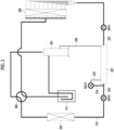
- FIG. 3 is a diagram illustrating a system of the air conditioner of FIG. 1 according to another embodiment.
- the indoor unit When the air conditioner is in a heating operation, the indoor unit may include a condenser 305 which corresponds to an indoor heat exchanger, and the outdoor unit may include an evaporator 309 which corresponds to an outdoor heat exchanger, a compressor 301, a four way valve 303, a subcooler 307, an accumulator 311.
- a refrigerant compressed by the compressor 301 may flow to the indoor heat exchanger 305 by the four way valve 303.
- the refrigerant discharged from the indoor heat exchanger 305 may flow to the subcooler 307, and refrigerant discharged from the subcooler 307 may flow to the outdoor heat exchanger 309.
- the description of FIG. 2 may be referred to.
- the evaporator which corresponds to the outdoor heat exchanger 309, may evaporate a liquid refrigerant into a gas refrigerant through heat exchange with outdoor air.
- the gas-liquid separator separates the gas refrigerant in the evaporator 309 and guides the gas refrigerant to the compressor 301.
- the gas-liquid separator includes a connection pipe 323 connected to a refrigerant pipe in the evaporator, the refrigerant pipe in which the two-phase refrigerant flows.
- the two-phase refrigerant includes the liquid refrigerant and the gas refrigerant.
- FIG. 4 may be referred to.
- the gas-liquid separator includes the connection pipe 323, a header 325, a flow rate control valve 327, and a bypass pipe 329.
- the flow rate control valve 327 which is a valve capable of controlling a flow rate of a refrigerant flowing through the bypass pipe 329, may include, for example, an electronic expansion valve (EEV) or a solenoid valve.
- the gas-liquid separator further includes a controller (not shown).
- a plurality of connection pipes 323 may be connected to the header 325, and the header 325 is connected to the bypass pipe 329 that guides a flow of a gas refrigerant to the compressor 301.
- the flow rate control valve 327 is installed at the bypass pipe 329. Specifically, when the flow rate control valve 327 is opened, the gas refrigerant flows to the compressor 301, and when the flow rate control valve 327 is closed, the gas refrigerant cannot flow to the compressor 301.
- the first preset condition may be a condition for extracting a gas refrigerant from a two-phase refrigerant flowing inside the evaporator 309
- the second preset condition may be a condition for ensuring reliability of the gas-liquid separator.
- a liquid refrigerant as well as the gas refrigerant may be included, and thus, the reliability of the air conditioner may be deteriorated.
- the opening or closing of the flow rate control valve 327 is adjusted by the controller (not shown).
- the controller adjusts the opening or closing of the flow rate control valve 327 based on relevant information. A detailed description about how to open and close the flow rate control valve 327 by the controller will be described later.
- the gas refrigerant flowing through the refrigerant pipe inside the evaporator 309 flows in the form of an annular flow
- the gas refrigerant is separated from the two-phase refrigerant through a connection pipe 323.
- the separated gas refrigerant flows to the compressor 301 through the bypass pipe 329 connected to the header 325.
- the flow rate control valve 327 is opened before the annular flow occurs, the liquid refrigerant as well as the gas refrigerant may flow to the compressor 301 through the bypass pipe 329, and thus, the reliability of the air conditioner may be deteriorated. How to maintain the reliability of the air conditioner will be hereinafter described in detail.
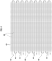
- FIG. 4 is a diagram illustrating a refrigerant pipe of an evaporator according to an embodiment.
- the evaporator which corresponds to the outdoor heat exchanger, may include a plurality of refrigerant flow channels 410, 430, and 450, through which a two-phase refrigerant flows, and a plurality of heat exchange pins 470.
- a plurality of connection pipes 323 of the gas-liquid separator may be connected to a plurality of refrigerant pipes 411, 431, and 451, and a gas refrigerant may be separated from the refrigerant pipes 411, 431, 451 and flow to the plurality of connection pipes 323.
- the plurality of refrigerant flow channels 410, 430, and 450 shown in FIG. 4 , the plurality of heat exchange pins 470, and a plurality of refrigerant straight-type pipes 490 are merely examples, and the scope of the present disclosure is not limited thereto.
- the plurality of refrigerant flow channels 410, 430, and 450 may penetrate the plurality of heat exchange pins 470.
- the plurality of heat exchange pins 470 may have through holes respectively formed therein, and the plurality of refrigerant flow channels 410, 430, and 450 may pass through the respective through holes.
- outer circumferential surfaces of the plurality of refrigerant flow channels 410, 430, and 450 may contact inner circumferential surfaces of the respective through holes.
- the plurality of heat exchange pins 470 may contact air, thereby improving heat exchange performance between a refrigerant flowing inside the plurality of refrigerant flow channels 410, 430, and 450 and air existing outside the plurality of refrigerant flow channels 410, 430, and 450.
- the plurality of heat exchange pins 470 each may be formed in a quadrilateral shape, for example.
- the plurality of heat exchange pins 470 may have one surface disposed parallel to one another.
- the plurality of connection pipes 323 of the gas-liquid separator may be installed to correspond to the plurality of refrigerant flow channels. For example, if there are ten refrigerant flow channels, the number of the connection pipes 323 may be 10 as shown in FIG. 3 , or if there are three refrigerant flow channels 410, 430, and 450, the number of the connection pipes 323 may be 3 as shown in FIG. 4 . Alternatively, at least one connection pipe 323 may correspond to one refrigerant flow channel. For example, ten connection pipes 323 of FIG. 3 may be connected to one refrigerant flow channel 410.
- the refrigerant flow channel 410 may include the plurality of refrigerant straight-type pipes 490 and a plurality of refrigerant pipes 411 and 413.
- the plurality of refrigerant straight-type pipes 490 each may be formed straight in a longitudinal direction thereof.
- the plurality of refrigerant straight-type pipes 490 each may be disposed parallel to one another.
- the plurality of refrigerant straight-type pipes 490 may pass through the plurality of heat exchange pins 470.
- the plurality of heat exchange pins 470 may have through holes respectively formed therein, and the plurality of refrigerant straight-type pipes 490 may pass through the respective through holes.
- the refrigerant pipe 413 included in the refrigerant flow channel 410 may be a U-shaped refrigerant pipe, and the refrigerant pipe 411 included in the refrigerant flow channel 410 may be an h-shaped refrigerant pipe.
- the U-shaped refrigerant pipe 413 may connect refrigerant pipes 490 adjacent to each other among the plurality of refrigerant pipes 490.
- At least one h-shaped refrigerant pipe 411 may be disposed at the refrigerant flow channel 410.
- the gas refrigerant may be separated from the two-phase refrigerant through the refrigerant pipe 411.
- the refrigerant flow channels 430 and 450 may be applied in the same manner as the refrigerant flow channels 410.
- FIG. 5 is a diagram illustrating a flow pattern of a liquid refrigerant and a gas refrigerant according to an embodiment.
- a flow pattern of a two-phase refrigerant including the liquid refrigerant and the gas refrigerant may change depending on a dryness and a flow velocity.
- the liquid refrigerant may flow along a wall surface of a refrigerant pipe and the gas refrigerant may flow inside the liquid refrigerant.
- the liquid refrigerant and the gas refrigerant may be separated.
- a flow pattern occurring when a liquid refrigerant and a gas refrigerant are separated and flow inside a refrigerant pipe may be referred to as an annular flow.
- the liquid refrigerant may flow along a wall surface of a refrigerant pipe 501 and the gas refrigerant may flow inside the liquid refrigerant.
- the gas refrigerant may flow to a header 505 through a connection pipe, and the liquid refrigerant may flow to a refrigerant pipe 503.
- a flow pattern such as the annular flow may occur when the two-phase refrigerant flows in a refrigerant pipe at a predetermined flow velocity or higher.
- FIG. 6 is a diagram illustrating a control of a flow rate control valve installed on a bypass pipe according to the embodiment.
- An air conditioner may include a compressor for compressing refrigerant, a condenser for condensing refrigerant compressed in the compressor, a subcooler for subcooling refrigerant passing through the condenser, and an evaporator for evaporating refrigerant passing through the subcooler.
- the air conditioner further includes a gas-liquid separator for separating a gas refrigerant from a two-phase refrigerant (including a liquid refrigerant and the gas refrigerant) flowing inside a refrigerant pipe of the evaporator.
- the gas-liquid separator includes a connection pipe connected to the refrigerant pipe in the evaporator, the refrigerant pipe in which the two-phase refrigerant flows, a header connected to the connection pipe, a bypass pipe connected to the header to guide a flow of the gas refrigerant to the compressor, a flow rate control valve installed on the bypass pipe to control the flow of the gas refrigerant to the compressor, and a controller (not shown).
- Opening or closing of the flow rate control valve is controlled by the controller (not shown).
- the controller adjusts the opening or closing of the flow rate control valve based on relevant information.
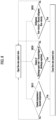
- the controller included in the gas-liquid separator controls the flow rate control valve to be opened or closed according to whether a first preset condition is satisfied in operation S610.
- the flow rate control valve may be opened in operation S620, or when a second preset condition is satisfied, the flow rate control valve may be closed in operation S640.
- the opening or closing of the flow rate control valve may be controlled according to whether the second preset condition is satisfied in operation S630.
- the flow rate control valve When the second preset condition is not satisfied, the flow rate control valve may be opened in operation S620, and when the second preset condition is satisfied, the flow rate control valve may be closed in operation S640.
- the first preset condition and the second preset condition may be related to an outside temperature, a degree of discharge superheat, a refrigerant flow velocity, and elapse of a predetermined period of time.
- a refrigerant flow velocity of a two-phase refrigerant flowing inside an evaporator is estimated in consideration of at least one of the following: a type of the compressor, a frequency of the compressor, the number of paths of the evaporator, and an outside temperature.
- the estimated refrigerant flow velocity will be referred to as a first refrigerant flow velocity.
- the first refrigerant flow velocity (kg/m2s) may be determined by Equation 1 below. N / P ⁇ A ⁇ Outside Temperature + B
- N may be determined according to a compressor type
- P may be determined as a current number of paths of the evaporator compared to 10 paths
- a and B may be statistical values determined according to a current frequency. For example, if the current number of paths of the evaporator is 12, P may be 1.2, and N may be a predetermined value according to a compressor type.
- a and B may be determined by Equation 2 below.
- A1, A2, B1, and B2 may be statistical values determined by experiments.
- A A 1 * Frequency + A 2
- B B 1 * Frequency + B 2
- a second refrigerant flow velocity may be a flow velocity of the two-phase refrigerant when flowing in the form of an annular flow in the refrigerant pipe of the evaporator, and the second refrigerant flow velocity may be determined by Equation 3 below.
- C and D may be statistical values determined by experiments. X * OutsideTemperature + D
- the controller controls the flow rate control valve to be opened so that a gas refrigerant can flow from the evaporator to the compressor.
- the controller may control the flow rate control valve to be opened, so that the gas refrigerant flows from the evaporator to the compressor.
- the controller may control the flow velocity control valve to be closed, so that the gas refrigerant is prevented from flowing to the compressor.
- the predetermined ratio which is a ratio that takes into consideration a margin between the first refrigerant flow velocity and the second refrigerant flow velocity, may be a value set for reliability.
- the predetermined ratio may be 1.1, and in the case where it is determined that reliability is ensured when the first refrigerant flow velocity is 20% greater than the second refrigerant flow velocity, the predetermined ratio may be 1.2.
- the controller may open or close the flow rate control valve according to a degree of discharge superheat.
- the degree of discharge superheat which is a difference between a discharge temperature of the compressor and a condensation temperature of a refrigerant, may be a difference between a temperature measured in the compressor and a temperature measured in the condenser.
- the controller may open the flow rate control valve and thus the gas refrigerant may flow from the evaporator to the compressor.
- the controller may close the flow rate control valve and thus the gas refrigerant may not flow from the evaporator to the compressor.
- the flow rate control valve may be opened so that gas refrigerant flows to the compressor.
- the degree of discharge superheat is measured as 13°C
- the flow rate control valve may be closed so that the gas refrigerant is prevented from flowing to the compressor.
- the opened flow rate control valve may remain open, but when the degree of discharge superheat changes from 20°C to 13°C, the opened flow rate control valve may be closed.
- the first degree of discharge superheat and the second degree of discharge superheat may be statistical values that are preset in consideration of reliability of the air conditioner.
- the flow rate control valve may not be opened.
- the preset period of time may be a statistical value that is preset in consideration of reliability of the air conditioner. For example, when 10 minutes have not elapsed since activation of the air conditioner, the flow rate control valve may not be opened. In addition, when 5 minutes have not elapsed since closing of the flow rate control valve, the flow rate control valve may not be opened.
- the flow rate control valve may be opened when the outside temperature is equal to or less than a first preset temperature, or the flow rate control valve may be closed when the outside temperature is equal to or higher than a second preset temperature.
- the second temperature may be a value determined in consideration of the first temperature and a hysteresis gap.
- the flow rate control valve may be opened when the outside temperature is 9°C, and the flow rate control valve may be closed when the outside temperature is 14°C.
- the opened flow rate control valve may remain opened, but if the outside temperature changes from 9°C to 14°C, the opened flow rate control valve may be closed.
- the flow rate control valve included in the gas-liquid separator may be opened to guide gas refrigerant to the compressor, and when a different condition is satisfied, the flow rate control valve may be closed to prevent gas refrigerant from being guided to the compressor.
- the flow rate control valve may be opened or closed.
- FIG. 7 is a diagram illustrating a control of a flow rate control valve installed on a bypass pipe according to another embodiment.
- FIGS. 6 and 7 the description of FIG. 6 described above may be referred to.
- An outside temperature in the outside of the air conditioner may be monitored.
- an operation time of the air conditioner may be monitored, and a degree of discharge superheat may be monitored based on the compressor and the condenser.
- a refrigerant flow velocity of a refrigerant flowing inside a refrigerant pipe of the air conditioner may be estimated.
- the controller may identify whether an outside temperature is less than the first temperature in operation S710, the controller may identify whether a preset period of time has elapsed since activation of the air conditioner in operation S720, the controller may identify whether a degree of discharge superheat is greater than a first preset degree of discharge superheat in operation S730, and the controller may identify whether the refrigerant flow velocity is greater than a second refrigerant flow velocity at a predetermined ratio or more relative thereto in operation S740.
- the controller may control the flow rate control valve to be opened when the outside temperature of the air conditioner is less than the first temperature, when the preset period of time has elapsed since activation of the air conditioner, when the degree of discharge superheat is greater than the first degree of discharge superheat, and when the refrigerant flow velocity is greater than the second refrigerant flow velocity at a predetermined ratio or more relative thereto.
- the controller may control the flow rate control valve to be closed when the outside temperature of the air conditioner is less than the first temperature, when the preset period of time has elapsed since activation of the air conditioner, or when the degree of discharge superheat is less than the first degree of discharge superheat.
- FIG. 8 is a diagram illustrating a control of a flow rate control valve installed on a bypass pipe according to another embodiment.
- FIGS.6 and 8 the description of FIG. 6 described above may be referred to.
- the controller may identify whether an outside temperature of the air conditioner is greater than a second temperature in operation S810. When the outside temperature of the air conditioner is greater than the second temperature, the controller may close the opened flow rate control valve. Alternatively, when the outside temperature is less than the second temperature, the controller may maintain the flow rate control valve opened.
- the controller may identify whether a degree of discharge superheat of the air conditioner is less than a second degree of discharge superheat in operation S820. When the degree of discharge superheat of the air conditioner is less than the second degree of discharge superheat, the controller may close the opened flow rate control valve. Alternatively, when the degree of discharge superheat is greater than the second degree of discharge superheat, the controller may maintain the flow rate control valve opened.
- the controller may identify whether an estimated refrigerant flow velocity of a two-phase refrigerant flowing inside a refrigerant pipe is less than the second refrigerant flow velocity at a predetermined ratio or more relative thereto in operation S830. If the estimated refrigerant flow velocity is not greater than the second refrigerant flow velocity at the predetermined ratio or more relative thereto, the controller may close the opened flow rate control valve. Alternatively, if the estimated refrigerant flow velocity is greater than the second refrigerant flow velocity at the predetermined ratio or more relative thereto, the controller may maintain the flow rate control valve opened.
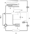
- FIG. 9 is a diagram illustrating a system of an air conditioner according to an embodiment different from the embodiment of FIG. 3 .
- the description of FIG. 3 described above may be referred to.
- the indoor unit may include a condenser 905 which corresponds to an indoor heat exchanger
- the outdoor unit may include an evaporator 909 which corresponds to an outdoor heat exchanger, a compressor 901, a four way valve 903, a subcooler 907, an accumulator 911.
- the gas-liquid separator separates the gas refrigerant in the evaporator 909 and guide the gas refrigerant to the compressor 901.
- the gas-liquid separator includes a connection pipe 913 connected to a refrigerant pipe in the evaporator, the refrigerant pipe in which the two-phase refrigerant flows.
- a plurality of connection pipes 913 may be connected to the header 915, and the header 915 is connected to the bypass pipe that guides a flow of a gas refrigerant to the compressor 901.
- the flow rate control valve 917 is installed at the bypass pipe.
- a subcooler 907 may include a first subcooler 907A and a second subcooler 907B.
- the first subcooler 907A may be a subcooler passed by a second bypass pipe, which is a refrigerant pipe connecting the compressor and the electronic expansion valve EEV3
- the second subcooler 907B may be a subcooler passed by a first bypass pipe 919 connected to the evaporator 909.
- One end of the second bypass pipe may be connected to a refrigerant pipe between the electronic expansion valve EEV2 and the subcooler 907A, and the other end of the second bypass pipe may be connected to a compressor 901.
- the description of FIG. 3 described above may be referred to.
- Refrigerant flowing inside the first bypass pipe 919 and the second bypass pipe may be subcooled by heat exchange with refrigerant flowing inside the subcoolers 907A and 907B.
- One end of the first bypass pipe 919 may be connected to a header 915, and the other end of the first bypass pipe 919 may be connected to a refrigerant pipe connecting an accumulator 911 and the compressor 901.
- the first bypass pipe 919 of FIG. 7 may pass through the second subcooler 907B, so that the refrigerant flowing inside the first bypass pipe 919 is subcooled.
- the first subcooler 907A and the second subcooler 907B may be arranged adjacent to each other in a refrigerant flow direction.
- the first subcooler 907A may be disposed behind the second subcooler 907B in the refrigerant flow direction in a heating operation of the air conditioner. That is, the second subcooler 907B may be disposed in front of the first subcooler 907A in the refrigerant flow direction in the heating operation of the air conditioner.
- the first bypass pipe 919 in which a gas refrigerant separated in the evaporator 909 flows may pass through the second subcooler 907B, so that the gas refrigerant is subcooled and flows to the compressor.
Landscapes
- Engineering & Computer Science (AREA)
- Mechanical Engineering (AREA)
- General Engineering & Computer Science (AREA)
- Physics & Mathematics (AREA)
- Thermal Sciences (AREA)
- Chemical & Material Sciences (AREA)
- Signal Processing (AREA)
- Combustion & Propulsion (AREA)
- Power Engineering (AREA)
- Fuzzy Systems (AREA)
- Mathematical Physics (AREA)
- Analytical Chemistry (AREA)
- Air Conditioning Control Device (AREA)
Description
- The present disclosure relates to a gas-liquid separator and an air conditioner including the same, and one particular embodiment relates to a gas-liquid separator for separating a gas refrigerant from a two-phase refrigerant flowing inside an evaporator and an air conditioner including the same.
- In general, an air conditioner is a device for cooling or heating indoor air using a refrigeration cycle device that is composed of a compressor, an outdoor heat exchanger, an expansion device, and an indoor heat exchanger.
- In the case of cooling indoor air, the outdoor heat exchanger functions as a condenser, the indoor heat exchanger functions as an evaporator, and refrigerant is circulated in the order of the compressor, the outdoor heat exchanger, the expansion device, the indoor heat exchanger, and the compressor.
- In the case of heating indoor air, the outdoor heat exchanger functions as an evaporator, the indoor heat exchanger functions as a condenser, and refrigerant is circulated in the order of the compressor, the indoor heat exchanger, the expansion mechanism, the outdoor heat exchanger, and the compressor.
- Related patent document 1 (
Korea Patent Application Publication No. 10-2018-0136693 Korean Patent Application Publication No. 10-2017-0031139 Korean Patent Application Publication No. 10-2018-0144475 - The pressure loss in the evaporator of the air conditioner may cause several problems. Accordingly, if a gas refrigerant is extracted from a two-phase refrigerant flowing inside the evaporator and then guided to the compressor, the efficiency of the air conditioner may be improved due to a pressure loss reduction. Thus, a technique for controlling the opening and closing of a flow rate control valve is required.
EP 3 511 655 discloses a configuration in which a bypass pipe is disposed between the entrance portion of a second header and a first header and configured to bypass refrigerant. A flow control valve in the bypass controls the flow rate of the refrigerant such that gas refrigerant is directed to the bypass pipe from the second header through which refrigerant in a two-phase gas-liquid state flows. As a result, the flow of refrigerant through the header pipe of the second header is adjusted such that it follows an annular or churn flow pattern in which a large amount of gas refrigerant is distributed close to the center of the main tube of the first header and a large amount of liquid refrigerant is distributed close to the wall surface of the main tube of the first header which improves the refrigerant distribution in the heat transfer tubes. - An aspect provides a technique related to a gas-liquid separator for separating a gas refrigerant from a two-phase refrigerant flowing inside an evaporator and an air conditioner including the gas-liquid separator. It will be appreciated by persons skilled in the art that the objects that could be achieved with the present disclosure are not limited to what has been particularly described hereinabove and the above and other objects that the present disclosure could achieve will be more clearly understood from the following detailed description.
- According to the present invention, there is provided an air conditioner as defined in claim 1.
- Specific details of other embodiments are included in the detailed description and drawings.
- The above and other aspects, features, and advantages of certain embodiments will be more apparent from the following detailed description taken in conjunction with the accompanying drawings, in which:
-
FIG. 1 is a diagram illustrating an air conditioner including an indoor unit and an outdoor unit according to an embodiment; -
FIG. 2 is a diagram showing a system of the air conditioner ofFIG. 1 according to an embodiment; -
FIG. 3 is a diagram illustrating a system of the air conditioner ofFIG. 1 according to another embodiment; -
FIG. 4 is a diagram illustrating a refrigerant pipe of an evaporator according to an embodiment; -
FIG. 5 is a diagram illustrating a flow pattern of a liquid refrigerant and a gas refrigerant according to an embodiment; -
FIG. 6 is a diagram illustrating a control of a flow rate control valve installed on a bypass pipe according to the embodiment; -
FIG. 7 is a diagram illustrating a control of a flow rate control valve installed on a bypass pipe according to another embodiment; -
FIG. 8 is a diagram illustrating a control of a flow rate control valve installed on a bypass pipe according to another embodiment; and -
FIG. 9 is a diagram illustrating a system of an air conditioner according to an embodiment different from the embodiment ofFIG. 3 . - Hereinafter, embodiments of the present invention will be described in detail with reference to the accompanying drawings.
- Hereinafter, exemplary embodiments disclosed herein will be described in detail with reference to the accompanying drawings, but the same or similar elements are assigned the same reference numbers regardless of the reference numerals, and overlapping descriptions thereof will be omitted. The suffixes "module" and "part" for components used in the following description are given or mixed only considering the ease of writing the specification, and do not have meanings or roles that are distinguished from each other. In addition, in the description of the embodiments disclosed herein, when it is determined that detailed descriptions of related known technologies may obscure the gist of the embodiments disclosed herein, detailed descriptions thereof will be omitted. In addition, the accompanying drawings are used to help easily understand various technical features and it should be understood that the embodiments presented herein are not limited by the accompanying drawings. As such, the present disclosure should be construed to extend to any alterations, equivalents and substitutes in addition to those which are particularly set out in the accompanying drawings.
- Terms including ordinal numbers such as first and second may be used to describe various components, but the components are not limited by the terms. The terms are used only for the purpose of distinguishing one component from other components.
- When an element is said to be "connected" or "connected" to another component, it is understood that other components may be directly connected to or connected to the other component, but there may be other components in between. On the other hand, when a component is said to be "directly connected" or "directly connected" to another component, it should be understood that no other component exists in the middle.
- Singular expressions include plural expressions unless the context clearly indicates otherwise.
- In this application, terms such as "comprises" or "have" are intended to indicate that a feature, number, step, operation, component, part, or combination thereof described in the specification exists, and that one or more other features are present. It should be understood that the existence or addition possibilities of fields or numbers, steps, operations, components, parts or combinations thereof are not excluded in advance.
- In describing the embodiments, descriptions of technical contents well known in the technical field to which the present disclosure pertains and which are not directly related to the present disclosure will be omitted. This is to more clearly and without obscuring the subject matter of the present disclosure by omitting unnecessary description.
- For the same reason, some components in the accompanying drawings are exaggerated, omitted, or schematically illustrated. Also, the size of each component does not entirely reflect the actual size. The same reference numbers are assigned to the same or corresponding elements in each drawing.
- Advantages and features of the present invention, and a method of achieving them will be apparent with reference to embodiments described below in detail together with the accompanying drawings. However, the present disclosure is not limited to the embodiments disclosed below, and may be implemented in various different forms, and only the embodiments allow the disclosure of the present disclosure to be complete, and common knowledge in the technical field to which the present disclosure pertains. It is provided to fully inform the holder of the scope of the invention, and the invention is only defined by the scope of the claims. The same reference numerals refer to the same components throughout the specification.
-
FIG. 1 is a diagram illustrating an air conditioner including an indoor unit and an outdoor unit according to an embodiment. - Referring to
FIG. 1 , an air conditioner may include anindoor unit 10 and anoutdoor unit 20. In the air conditioner, theindoor unit 10 is depicted as a standing type, but may be a wall-mounted type or a ceiling-mounted type. Theindoor unit 10 is not limited to a standing type, a wall-mounted type, or a ceiling type, and may be installed indoors in any of various shapes. - The
outdoor unit 20 may be connected to theindoor unit 10 and transfer refrigerant necessary for air conditioning in theindoor unit 10 to theindoor unit 10. Theindoor unit 10 may exchange heat between the transferred refrigerant and air, and discharge the heat-exchanged air into an indoor space. - The
indoor unit 10 and theoutdoor unit 20 may be connected through a refrigerant pipe so that a refrigerant circulates through theindoor unit 10 and theoutdoor unit 20 via the refrigerant pipe. Hot or cold air may be discharged into the indoor space from theindoor unit 10 that performs a heating operation or a cooling operation according to circulation of the refrigerant. At this point, at least oneindoor unit 10 may be connected to theoutdoor unit 20, andFIG. 1 shows connection between oneoutdoor unit 20 and oneindoor unit 10 as an example. - The
indoor unit 10 and theoutdoor unit 20 may be connected via a cable for communication, and hence, control commands may be transmitted or received according to a predetermined communication method. - The
indoor unit 10 may include an inlet for suctioning indoor air, and an outlet for discharging heat-exchanged air from an inside. Theindoor unit 10 may include an air direction control apparatus provided in the outlet. The air direction control apparatus may open and close the outlet or may control a direction of air discharged from the outlet. In addition, theindoor unit 10 may control a volume of air discharged from the outlet. Theindoor unit 10 may include a vane installed at the inlet or the outlet. The vane may open and close at least one of the inlet and the outlet, and may guide an air flow direction. - The
indoor unit 10 may further include a display for displaying an operating state and setting information of theindoor unit 10, and an input part for inputting setting data. When the user inputs an operation command for the air conditioner through the input part, theoutdoor unit 20 may be operated for a cooling operation or a heating operation in response to the input operation command. At this point, the user may input an operation command for the air conditioner manually or through communication. - When the air conditioner is in a cooling operation, the outdoor heat exchanger included in the outdoor unit functions as a condenser in which a gas refrigerant flowing to the outdoor heat exchanger can be condensed by outdoor air. Also, when the air conditioner is in a heating operation, the outdoor heat exchanger functions as an evaporator in which a liquid refrigerant flowing into the outdoor heat exchanger can be evaporated by outdoor air.
- The indoor unit may include an
indoor heat exchanger 11 for allowing heat exchange between indoor air and a refrigerant, and anindoor blower 12 for blowing the indoor air to theindoor heat exchanger 11. When the air conditioner is in a cooling operation, the indoor heat exchanger included in the indoor unit functions as an evaporator in which a liquid refrigerant flowing to the indoor heat exchanger can be evaporated by indoor air. In addition, when the air conditioner is in a heating operation, the indoor heat exchanger included in the indoor unit functions as a condenser in which a gas refrigerant flowing to the indoor heat exchanger can be condensed by indoor air. -
FIG. 2 is a diagram showing a system of the air conditioner ofFIG. 1 according to an embodiment. - The air conditioner may be operated by a
compressor 201, a fourway valve 203, acondenser 205, a flow rate control valve, asubcooler 207, anevaporator 209, and anaccumulator 211. - According to an embodiment, when the air conditioner is in a heating operation, the indoor unit may include the
condenser 205 which corresponds to an indoor heat exchanger, and the outdoor unit may include the outdoorheat exchanger evaporator 209, thecompressor 201, the fourway valve 203, thesubcooler 207, and theaccumulator 211. The fourway valve 203 may allow a refrigerant discharged from thecompressor 201 to flow either into the outdoor heat exchanger or into the indoor heat exchanger. The indoor unit and the outdoor unit are merely examples, and the air conditioner is not limited thereto. - The
accumulator 211 may separate a gas refrigerant from a two-phase refrigerant that includes a liquid refrigerant and the gas refrigerant. The liquid refrigerant separated in theaccumulator 211 may be received in a lower side of theaccumulator 211, and the gas refrigerant may be received above the separated liquid refrigerant. The gas refrigerant separated in theaccumulator 211 may flow to thecompressor 201, and the liquid refrigerant separated in theaccumulator 211 may remain in theaccumulator 211. - When the air conditioner is in a heating operation, a refrigerant may pass through the
compressor 201 and theindoor heat exchanger 205, expand in an electronic expansion device, and be then heat exchanged with outdoor air in theoutdoor heat exchanger 209. - Specifically, when the air conditioner is in the heating operation, a refrigerant discharged from the compressor may flow to the
indoor heat exchanger 205 by the fourway valve 203. The refrigerant condensed in theindoor heat exchanger 205 may be subcooled in thesubcooler 207 and then flow to theoutdoor heat exchanger 209. - The refrigerant condensed in the
indoor heat exchanger 205 may flow through arefrigerant pipe 231. The refrigerant may flow to thesubcooler 207 through arefrigerant pipe 232. Therefrigerant pipe 232 may be connected to thesubcooler 207 to guide the refrigerant transferred from therefrigerant pipe 231 to thesubcooler 207, and arefrigerant pipe 233 may guide discharge of a refrigerant which is heat-exchanged in thesubcooler 207. Hereinafter, the refrigerant flowing inside therefrigerant pipe 232 and therefrigerant pipe 233 will be referred to as a first refrigerant. - In some examples, the
subcooler 207 can include a heat exchanger or a refrigerant passage or pipe configured to exchange heat with the refrigerant that has passed through therefrigerant pipe 231. In some examples, thesubcooler 207 can be a portion of a refrigerant pipe that carries a liquid-phase refrigerant, a gas-phase refrigerant, or both. - An opening degree of each of a first electronic expansion valve EEV1 and a second electronic expansion valve EEV2 may be adjusted to or not to expand a refrigerant flowing therein. In a heating operation, the second electronic expansion valve EEV2 may be opened, and an opening degree of the first electronic expansion valve EEV1 may be adjusted. The second electronic expansion valve EEV2 may be installed at a refrigerant pipe between the
indoor heat exchanger 205 and thesubcooler 207, and the first electronic expansion valve EEV1 may be installed at a refrigerant pipe between theoutdoor heat exchanger 209 and thesubcooler 207. - In order to inject refrigerant into the
compressor 201, a portion of the first refrigerant may be branched by arefrigerant pipe 234. Hereinafter, the portion branched from the first refrigerant will be referred to as a second refrigerant. - The second refrigerant may flow through the
refrigerant pipe 234 to a third electronic expansion valve EEV3, and may flow from the electronic expansion valve EEV3 to arefrigerant pipe 235 through thesubcooler 207. The refrigerant discharged from thesubcooler 207 through arefrigerant pipe 236, which connects thesubcooler 207 and thecompressor 201, may flow to thecompressor 201. Therefore, the refrigerant discharged from thesubcooler 207 may be injected into thecompressor 201. - The first refrigerant may flow through a plurality of inner tubes inside the subcooler, and the second refrigerant may flow through an outer tube. At this point, the plurality of inner tubes may be arranged in the inner space of the
subcooler 207, and the first refrigerant flowing inside the plurality of inner tubes may be subject to heat exchange with the second refrigerant flowing inside the outer tube. - The second refrigerant may be expanded by the electronic expansion valve EEV3 to have a lower temperature and a lower pressure compared to the first refrigerant. The second refrigerant of the low temperature and the low pressure may be, while flowing inside the outer tube, heat exchanged with the first refrigerant which flows inside the plurality of inner tubes, and the first refrigerant may be subcooled. The first refrigerant may be heat exchanged with the indoor air, thereby being evaporated in the
outdoor heat exchanger 209. - According to another embodiment, when the air conditioner is in a cooling operation, the indoor unit may include an
evaporator 209 which corresponds to the indoor heat exchanger, and the outdoor unit may include acondenser 205 corresponding to the outdoor heat exchanger, acompressor 201, a fourway valve 203, asubcooler 207, and anaccumulator 211. The indoor unit and the outdoor unit are merely examples, and the air conditioner is not limited thereto. - The
accumulator 211 may separate a gas refrigerant from a two-phase refrigerant that includes a liquid refrigerant and the gas refrigerant. The liquid refrigerant separated in theaccumulator 211 may be received in a lower side of theaccumulator 211, and the gas refrigerant may be received above the separated liquid refrigerant. The gas refrigerant separated in theaccumulator 211 may flow to thecompressor 201, and the liquid refrigerant separated in theaccumulator 211 may remain in theaccumulator 211. - When the air conditioner is in a cooling operation, a refrigerant may pass through the
compressor 201 and theoutdoor heat exchanger 205, expand in an electronic expansion device, and be then heat exchanged with indoor air in theindoor heat exchanger 209. - Specifically, when the air conditioner is in the cooling operation, a refrigerant discharged from the
compressor 201 may flow to theoutdoor heat exchanger 205 by the fourway valve 203. The refrigerant condensed in theoutdoor heat exchanger 205 may be subcooled by thesubcooler 207 and then flow to theindoor heat exchanger 209. - The refrigerant condensed by the
outdoor heat exchanger 205 may flow through therefrigerant pipe 231. The refrigerant expanded by the second electronic expansion valve EEV2 may flow to thesubcooler 207 through therefrigerant pipe 232. Therefrigerant pipe 232 may be connected to thesubcooler 207 to guide the refrigerant transferred from therefrigerant pipe 231 to thesubcooler 207, and therefrigerant pipe 233 may guide refrigerant heat-exchanged in thesubcooler 207 to be discharged. Hereinafter, the refrigerant flowing inside therefrigerant pipe 232 and therefrigerant pipe 233 will be referred to as a first refrigerant. - An opening degree of each of the first electronic expansion valve EEV1 and the second electronic expansion valve EEV2 may be adjusted to or not to expand a refrigerant flowing therein. In a cooling operation, the first electronic expansion valve EEV1 may be opened, and an opening degree of the second electronic expansion valve EEV2 may be adjusted. The second electronic expansion valve EEV2 may be installed at a refrigerant pipe between the
outdoor heat exchanger 205 and thesubcooler 207, and the first electronic expansion valve EEV1 may be installed at a refrigerant pipe between theindoor heat exchanger 209 and thesubcooler 207. - In order to inject refrigerant into the
compressor 201, a portion of the first refrigerant may be branched by arefrigerant pipe 234. Hereinafter, the portion branched from the first refrigerant will be referred to as a second refrigerant. - The second refrigerant may flow through the
refrigerant pipe 234 to a third electronic expansion valve EEV3, and may flow from the electronic expansion valve EEV3 to arefrigerant pipe 235 through thesubcooler 207. The refrigerant discharged from thesubcooler 207 through arefrigerant pipe 236, which connects thesubcooler 207 and thecompressor 201, may flow to thecompressor 201. Therefore, the refrigerant discharged from thesubcooler 207 may be injected into thecompressor 201. - The first refrigerant may flow through a plurality of inner tubes inside the subcooler, and the second refrigerant may flow through an outer tube. At this point, the plurality of inner tubes may be arranged in the inner space of the
subcooler 207, and the first refrigerant flowing inside the plurality of inner tubes may be subject to heat exchange with the second refrigerant flowing inside the outer tube. - The second refrigerant may be expanded by the electronic expansion valve EEV3 to have a lower temperature and a lower pressure compared to the first refrigerant. The second refrigerant of the low temperature and the low pressure may be, while flowing inside the outer tube, heat exchanged with the first refrigerant which flows inside the plurality of inner tubes, and the first refrigerant may be subcooled. The first refrigerant may be heat exchanged with indoor air and evaporated in the
indoor heat exchanger 209. -
FIG. 3 is a diagram illustrating a system of the air conditioner ofFIG. 1 according to another embodiment. - When the air conditioner is in a heating operation, the indoor unit may include a
condenser 305 which corresponds to an indoor heat exchanger, and the outdoor unit may include anevaporator 309 which corresponds to an outdoor heat exchanger, acompressor 301, a fourway valve 303, asubcooler 307, anaccumulator 311. A refrigerant compressed by thecompressor 301 may flow to theindoor heat exchanger 305 by the fourway valve 303. The refrigerant discharged from theindoor heat exchanger 305 may flow to thesubcooler 307, and refrigerant discharged from thesubcooler 307 may flow to theoutdoor heat exchanger 309. For more details regarding the above, the description ofFIG. 2 may be referred to. - In this case, the evaporator, which corresponds to the
outdoor heat exchanger 309, may evaporate a liquid refrigerant into a gas refrigerant through heat exchange with outdoor air. - According to the present invention, the gas-liquid separator separates the gas refrigerant in the
evaporator 309 and guides the gas refrigerant to thecompressor 301. The gas-liquid separator includes aconnection pipe 323 connected to a refrigerant pipe in the evaporator, the refrigerant pipe in which the two-phase refrigerant flows. Here, the two-phase refrigerant includes the liquid refrigerant and the gas refrigerant. For more details about theconnection pipe 323 connected to the refrigerant pipe through which the two-phase refrigerant flows,FIG. 4 may be referred to. - The gas-liquid separator, according to the invention, includes the
connection pipe 323, aheader 325, a flowrate control valve 327, and abypass pipe 329. The flowrate control valve 327, which is a valve capable of controlling a flow rate of a refrigerant flowing through thebypass pipe 329, may include, for example, an electronic expansion valve (EEV) or a solenoid valve. The gas-liquid separator further includes a controller (not shown). - A plurality of
connection pipes 323 may be connected to theheader 325, and theheader 325 is connected to thebypass pipe 329 that guides a flow of a gas refrigerant to thecompressor 301. The flowrate control valve 327 is installed at thebypass pipe 329. Specifically, when the flowrate control valve 327 is opened, the gas refrigerant flows to thecompressor 301, and when the flowrate control valve 327 is closed, the gas refrigerant cannot flow to thecompressor 301. - When a first preset condition is satisfied, the flow
rate control valve 327 is opened, and when a second preset condition is satisfied, the flowrate control valve 327 is closed. The first preset condition may be a condition for extracting a gas refrigerant from a two-phase refrigerant flowing inside theevaporator 309, and the second preset condition may be a condition for ensuring reliability of the gas-liquid separator. Specifically, when the second preset condition is satisfied, a liquid refrigerant as well as the gas refrigerant may be included, and thus, the reliability of the air conditioner may be deteriorated. - The opening or closing of the flow
rate control valve 327 is adjusted by the controller (not shown). The controller adjusts the opening or closing of the flowrate control valve 327 based on relevant information. A detailed description about how to open and close the flowrate control valve 327 by the controller will be described later. - When the two-phase refrigerant flowing through the refrigerant pipe inside the
evaporator 309 flows in the form of an annular flow, the gas refrigerant is separated from the two-phase refrigerant through aconnection pipe 323. The separated gas refrigerant flows to thecompressor 301 through thebypass pipe 329 connected to theheader 325. When the flowrate control valve 327 is opened before the annular flow occurs, the liquid refrigerant as well as the gas refrigerant may flow to thecompressor 301 through thebypass pipe 329, and thus, the reliability of the air conditioner may be deteriorated. How to maintain the reliability of the air conditioner will be hereinafter described in detail. -
FIG. 4 is a diagram illustrating a refrigerant pipe of an evaporator according to an embodiment. - The evaporator, which corresponds to the outdoor heat exchanger, may include a plurality of refrigerant flow channels 410, 430, and 450, through which a two-phase refrigerant flows, and a plurality of heat exchange pins 470. A plurality of
connection pipes 323 of the gas-liquid separator may be connected to a plurality ofrefrigerant pipes 411, 431, and 451, and a gas refrigerant may be separated from therefrigerant pipes 411, 431, 451 and flow to the plurality ofconnection pipes 323. Here, the plurality of refrigerant flow channels 410, 430, and 450 shown inFIG. 4 , the plurality of heat exchange pins 470, and a plurality of refrigerant straight-type pipes 490 are merely examples, and the scope of the present disclosure is not limited thereto. - The plurality of refrigerant flow channels 410, 430, and 450 may penetrate the plurality of heat exchange pins 470. The plurality of heat exchange pins 470 may have through holes respectively formed therein, and the plurality of refrigerant flow channels 410, 430, and 450 may pass through the respective through holes. In a state in which the plurality of refrigerant flow channels 410, 430, and 450 passes through the respective through holes, outer circumferential surfaces of the plurality of refrigerant flow channels 410, 430, and 450 may contact inner circumferential surfaces of the respective through holes.
- The plurality of heat exchange pins 470 may contact air, thereby improving heat exchange performance between a refrigerant flowing inside the plurality of refrigerant flow channels 410, 430, and 450 and air existing outside the plurality of refrigerant flow channels 410, 430, and 450. The plurality of heat exchange pins 470 each may be formed in a quadrilateral shape, for example. The plurality of heat exchange pins 470 may have one surface disposed parallel to one another.
- The plurality of
connection pipes 323 of the gas-liquid separator may be installed to correspond to the plurality of refrigerant flow channels. For example, if there are ten refrigerant flow channels, the number of theconnection pipes 323 may be 10 as shown inFIG. 3 , or if there are three refrigerant flow channels 410, 430, and 450, the number of theconnection pipes 323 may be 3 as shown inFIG. 4 . Alternatively, at least oneconnection pipe 323 may correspond to one refrigerant flow channel. For example, tenconnection pipes 323 ofFIG. 3 may be connected to one refrigerant flow channel 410. - The refrigerant flow channel 410 may include the plurality of refrigerant straight-
type pipes 490 and a plurality of refrigerant pipes 411 and 413. The plurality of refrigerant straight-type pipes 490 each may be formed straight in a longitudinal direction thereof. The plurality of refrigerant straight-type pipes 490 each may be disposed parallel to one another. The plurality of refrigerant straight-type pipes 490 may pass through the plurality of heat exchange pins 470. The plurality of heat exchange pins 470 may have through holes respectively formed therein, and the plurality of refrigerant straight-type pipes 490 may pass through the respective through holes. In a state in which the plurality of refrigerant straight-type pipes 490 pass through the respective through holes, outer circumferential surfaces of the plurality of refrigerant straight-type pipes 490 may contact inner circumferential surfaces of the respective through holes. The refrigerant pipe 413 included in the refrigerant flow channel 410 may be a U-shaped refrigerant pipe, and the refrigerant pipe 411 included in the refrigerant flow channel 410 may be an h-shaped refrigerant pipe. The U-shaped refrigerant pipe 413 may connectrefrigerant pipes 490 adjacent to each other among the plurality ofrefrigerant pipes 490. At least one h-shaped refrigerant pipe 411 may be disposed at the refrigerant flow channel 410. The gas refrigerant may be separated from the two-phase refrigerant through the refrigerant pipe 411. The refrigerant flow channels 430 and 450 may be applied in the same manner as the refrigerant flow channels 410. -
FIG. 5 is a diagram illustrating a flow pattern of a liquid refrigerant and a gas refrigerant according to an embodiment. - A flow pattern of a two-phase refrigerant including the liquid refrigerant and the gas refrigerant may change depending on a dryness and a flow velocity. When a constant dryness and a constant flow velocity are ensured, the liquid refrigerant may flow along a wall surface of a refrigerant pipe and the gas refrigerant may flow inside the liquid refrigerant. As a result, the liquid refrigerant and the gas refrigerant may be separated. A flow pattern occurring when a liquid refrigerant and a gas refrigerant are separated and flow inside a refrigerant pipe may be referred to as an annular flow.
- When the annular flow occurs, the liquid refrigerant may flow along a wall surface of a
refrigerant pipe 501 and the gas refrigerant may flow inside the liquid refrigerant. In this case, the gas refrigerant may flow to aheader 505 through a connection pipe, and the liquid refrigerant may flow to arefrigerant pipe 503. A flow pattern such as the annular flow may occur when the two-phase refrigerant flows in a refrigerant pipe at a predetermined flow velocity or higher. A detailed description about an annular flow in which only the gas refrigerant is separated from the two-phase refrigerant flowing inside therefrigerant pipe 501 will be described later. -
FIG. 6 is a diagram illustrating a control of a flow rate control valve installed on a bypass pipe according to the embodiment. - An air conditioner may include a compressor for compressing refrigerant, a condenser for condensing refrigerant compressed in the compressor, a subcooler for subcooling refrigerant passing through the condenser, and an evaporator for evaporating refrigerant passing through the subcooler.
- According to the invention, the air conditioner further includes a gas-liquid separator for separating a gas refrigerant from a two-phase refrigerant (including a liquid refrigerant and the gas refrigerant) flowing inside a refrigerant pipe of the evaporator. The gas-liquid separator includes a connection pipe connected to the refrigerant pipe in the evaporator, the refrigerant pipe in which the two-phase refrigerant flows, a header connected to the connection pipe, a bypass pipe connected to the header to guide a flow of the gas refrigerant to the compressor, a flow rate control valve installed on the bypass pipe to control the flow of the gas refrigerant to the compressor, and a controller (not shown).
- Opening or closing of the flow rate control valve is controlled by the controller (not shown). The controller adjusts the opening or closing of the flow rate control valve based on relevant information. Specifically, the controller included in the gas-liquid separator controls the flow rate control valve to be opened or closed according to whether a first preset condition is satisfied in operation S610. When the first preset condition is satisfied, the flow rate control valve may be opened in operation S620, or when a second preset condition is satisfied, the flow rate control valve may be closed in operation S640. When the flow rate control valve is opened in operation S620, the opening or closing of the flow rate control valve may be controlled according to whether the second preset condition is satisfied in operation S630. When the second preset condition is not satisfied, the flow rate control valve may be opened in operation S620, and when the second preset condition is satisfied, the flow rate control valve may be closed in operation S640. The first preset condition and the second preset condition may be related to an outside temperature, a degree of discharge superheat, a refrigerant flow velocity, and elapse of a predetermined period of time. Hereinafter, the above will be described in more detail.
- According to the invention, a refrigerant flow velocity of a two-phase refrigerant flowing inside an evaporator is estimated in consideration of at least one of the following: a type of the compressor, a frequency of the compressor, the number of paths of the evaporator, and an outside temperature. Hereinafter, the estimated refrigerant flow velocity will be referred to as a first refrigerant flow velocity. The first refrigerant flow velocity (kg/m2s) may be determined by Equation 1 below.

- Here, N may be determined according to a compressor type, P may be determined as a current number of paths of the evaporator compared to 10 paths, and A and B may be statistical values determined according to a current frequency. For example, if the current number of paths of the evaporator is 12, P may be 1.2, and N may be a predetermined value according to a compressor type. Also, A and B may be determined by Equation 2 below. Here, A1, A2, B1, and B2 may be statistical values determined by experiments.

- A second refrigerant flow velocity may be a flow velocity of the two-phase refrigerant when flowing in the form of an annular flow in the refrigerant pipe of the evaporator, and the second refrigerant flow velocity may be determined by Equation 3 below. Here, C and D may be statistical values determined by experiments.

- Based on a comparison between an estimated first refrigerant flow velocity and an estimated second refrigerant flow velocity, the controller controls the flow rate control valve to be opened so that a gas refrigerant can flow from the evaporator to the compressor. Specifically, when the first refrigerant flow velocity is not greater than the second refrigerant flow velocity at a predetermined ratio or more relative thereto, the controller may control the flow rate control valve to be opened, so that the gas refrigerant flows from the evaporator to the compressor. Alternatively, when the first refrigerant flow velocity is not greater than the second refrigerant flow velocity at the predetermined ratio or more relative thereto, the controller may control the flow velocity control valve to be closed, so that the gas refrigerant is prevented from flowing to the compressor. At this point, the predetermined ratio, which is a ratio that takes into consideration a margin between the first refrigerant flow velocity and the second refrigerant flow velocity, may be a value set for reliability. For example, in the case where it is determined that reliability is ensured when the first refrigerant flow velocity is 10% greater than the second refrigerant flow velocity, the predetermined ratio may be 1.1, and in the case where it is determined that reliability is ensured when the first refrigerant flow velocity is 20% greater than the second refrigerant flow velocity, the predetermined ratio may be 1.2.
- In addition, the controller may open or close the flow rate control valve according to a degree of discharge superheat. The degree of discharge superheat, which is a difference between a discharge temperature of the compressor and a condensation temperature of a refrigerant, may be a difference between a temperature measured in the compressor and a temperature measured in the condenser. Specifically, when the degree of discharge superheat is equal to or greater than a first preset degree of discharge superheat, the controller may open the flow rate control valve and thus the gas refrigerant may flow from the evaporator to the compressor. When the degree of discharge superheat is equal to or less than a second preset degree of discharge superheat, the controller may close the flow rate control valve and thus the gas refrigerant may not flow from the evaporator to the compressor. For example, in the case where the first degree of discharge superheat is set to 19°C and the second degree of discharge superheat is set to 15°C, if a measured degree of discharge superheat is 20°C, the flow rate control valve may be opened so that gas refrigerant flows to the compressor. However, when the degree of discharge superheat is measured as 13°C, the flow rate control valve may be closed so that the gas refrigerant is prevented from flowing to the compressor. Alternatively, when the degree of discharge superheat changes from 20°C to 17°C, the opened flow rate control valve may remain open, but when the degree of discharge superheat changes from 20°C to 13°C, the opened flow rate control valve may be closed. At this point, the first degree of discharge superheat and the second degree of discharge superheat may be statistical values that are preset in consideration of reliability of the air conditioner.
- In addition, when a preset period of time has elapsed since activation of the air conditioner or when the preset period of time has not elapsed since closing of the flow rate control valve, the flow rate control valve may not be opened. At this point, the preset period of time may be a statistical value that is preset in consideration of reliability of the air conditioner. For example, when 10 minutes have not elapsed since activation of the air conditioner, the flow rate control valve may not be opened. In addition, when 5 minutes have not elapsed since closing of the flow rate control valve, the flow rate control valve may not be opened.
- In addition, the flow rate control valve may be opened when the outside temperature is equal to or less than a first preset temperature, or the flow rate control valve may be closed when the outside temperature is equal to or higher than a second preset temperature. At this point, the second temperature may be a value determined in consideration of the first temperature and a hysteresis gap. For example, in the case where the first temperature is set to 10°C and the second temperature is set to 13°C, the flow rate control valve may be opened when the outside temperature is 9°C, and the flow rate control valve may be closed when the outside temperature is 14°C. Alternatively, if the outside temperature changes from 9°C to 12°C, the opened flow rate control valve may remain opened, but if the outside temperature changes from 9°C to 14°C, the opened flow rate control valve may be closed.
- As described above, when a specific condition is satisfied, the flow rate control valve included in the gas-liquid separator may be opened to guide gas refrigerant to the compressor, and when a different condition is satisfied, the flow rate control valve may be closed to prevent gas refrigerant from being guided to the compressor. When at least one of the refrigerant flow velocity, the degree of discharge superheat, the outside temperature, and the elapse of the preset period of time is satisfied, the flow rate control valve may be opened or closed.
-
FIG. 7 is a diagram illustrating a control of a flow rate control valve installed on a bypass pipe according to another embodiment. For the common part ofFIGS. 6 and7 , the description ofFIG. 6 described above may be referred to. - An outside temperature in the outside of the air conditioner may be monitored. In addition, an operation time of the air conditioner may be monitored, and a degree of discharge superheat may be monitored based on the compressor and the condenser. Also, a refrigerant flow velocity of a refrigerant flowing inside a refrigerant pipe of the air conditioner may be estimated.
- Specifically, the controller may identify whether an outside temperature is less than the first temperature in operation S710, the controller may identify whether a preset period of time has elapsed since activation of the air conditioner in operation S720, the controller may identify whether a degree of discharge superheat is greater than a first preset degree of discharge superheat in operation S730, and the controller may identify whether the refrigerant flow velocity is greater than a second refrigerant flow velocity at a predetermined ratio or more relative thereto in operation S740.
- For example, the controller may control the flow rate control valve to be opened when the outside temperature of the air conditioner is less than the first temperature, when the preset period of time has elapsed since activation of the air conditioner, when the degree of discharge superheat is greater than the first degree of discharge superheat, and when the refrigerant flow velocity is greater than the second refrigerant flow velocity at a predetermined ratio or more relative thereto. In another example, the controller may control the flow rate control valve to be closed when the outside temperature of the air conditioner is less than the first temperature, when the preset period of time has elapsed since activation of the air conditioner, or when the degree of discharge superheat is less than the first degree of discharge superheat.
-
FIG. 8 is a diagram illustrating a control of a flow rate control valve installed on a bypass pipe according to another embodiment. For the common parts ofFIGS.6 and8 , the description ofFIG. 6 described above may be referred to. - When the flow rate control valve is opened, the controller may identify whether an outside temperature of the air conditioner is greater than a second temperature in operation S810. When the outside temperature of the air conditioner is greater than the second temperature, the controller may close the opened flow rate control valve. Alternatively, when the outside temperature is less than the second temperature, the controller may maintain the flow rate control valve opened.
- In addition, when the flow rate control valve is opened, the controller may identify whether a degree of discharge superheat of the air conditioner is less than a second degree of discharge superheat in operation S820. When the degree of discharge superheat of the air conditioner is less than the second degree of discharge superheat, the controller may close the opened flow rate control valve. Alternatively, when the degree of discharge superheat is greater than the second degree of discharge superheat, the controller may maintain the flow rate control valve opened.
- In addition, when the flow velocity control valve is opened, the controller may identify whether an estimated refrigerant flow velocity of a two-phase refrigerant flowing inside a refrigerant pipe is less than the second refrigerant flow velocity at a predetermined ratio or more relative thereto in operation S830. If the estimated refrigerant flow velocity is not greater than the second refrigerant flow velocity at the predetermined ratio or more relative thereto, the controller may close the opened flow rate control valve. Alternatively, if the estimated refrigerant flow velocity is greater than the second refrigerant flow velocity at the predetermined ratio or more relative thereto, the controller may maintain the flow rate control valve opened.
-
FIG. 9 is a diagram illustrating a system of an air conditioner according to an embodiment different from the embodiment ofFIG. 3 . For the common part ofFIGS. 3 and9 , the description ofFIG. 3 described above may be referred to. - When the air conditioner is in a heating operation, the indoor unit may include a
condenser 905 which corresponds to an indoor heat exchanger, and the outdoor unit may include anevaporator 909 which corresponds to an outdoor heat exchanger, acompressor 901, a fourway valve 903, asubcooler 907, anaccumulator 911. - The gas-liquid separator separates the gas refrigerant in the
evaporator 909 and guide the gas refrigerant to thecompressor 901. The gas-liquid separator includes aconnection pipe 913 connected to a refrigerant pipe in the evaporator, the refrigerant pipe in which the two-phase refrigerant flows. - A plurality of
connection pipes 913 may be connected to theheader 915, and theheader 915 is connected to the bypass pipe that guides a flow of a gas refrigerant to thecompressor 901. The flowrate control valve 917 is installed at the bypass pipe. - A
subcooler 907 may include afirst subcooler 907A and asecond subcooler 907B. In this case, thefirst subcooler 907A may be a subcooler passed by a second bypass pipe, which is a refrigerant pipe connecting the compressor and the electronic expansion valve EEV3, and thesecond subcooler 907B may be a subcooler passed by afirst bypass pipe 919 connected to theevaporator 909. One end of the second bypass pipe may be connected to a refrigerant pipe between the electronic expansion valve EEV2 and thesubcooler 907A, and the other end of the second bypass pipe may be connected to acompressor 901. For a detailed description of the second bypass pipe, the description ofFIG. 3 described above may be referred to. - Refrigerant flowing inside the
first bypass pipe 919 and the second bypass pipe may be subcooled by heat exchange with refrigerant flowing inside thesubcoolers first bypass pipe 919 may be connected to aheader 915, and the other end of thefirst bypass pipe 919 may be connected to a refrigerant pipe connecting anaccumulator 911 and thecompressor 901. UnlikeFIG. 3 , thefirst bypass pipe 919 ofFIG. 7 may pass through thesecond subcooler 907B, so that the refrigerant flowing inside thefirst bypass pipe 919 is subcooled. - The
first subcooler 907A and thesecond subcooler 907B may be arranged adjacent to each other in a refrigerant flow direction. Thefirst subcooler 907A may be disposed behind thesecond subcooler 907B in the refrigerant flow direction in a heating operation of the air conditioner. That is, thesecond subcooler 907B may be disposed in front of thefirst subcooler 907A in the refrigerant flow direction in the heating operation of the air conditioner. - According to an embodiment, unlike
FIG. 3 , inFIG. 7 , thefirst bypass pipe 919 in which a gas refrigerant separated in theevaporator 909 flows may pass through thesecond subcooler 907B, so that the gas refrigerant is subcooled and flows to the compressor. - According to an embodiment of the present specification, one or more of the following effects are provided.
- First, it is possible to improve efficiency of the air conditioner by a pressure loss reduction using a gas-liquid separator that extracts a gas refrigerant from a two-phase refrigerant, flowing inside an evaporator, in a heating operation of the air conditioner.
- Second, it is possible to improve reliability of the air conditioner by controlling a flow rate control valve included in the gas-liquid separator based on a flow pattern of the two-phase refrigerant flowing inside the evaporator. In this case, if the flow rate control valve is opened, the gas refrigerant is extracted in the evaporator and supplied to the compressor, thereby improving efficiency of the air conditioner by a pressure loss reduction.
- Third, it is possible to improve the reliability of the air conditioner by controlling the flow rate control valve included in the gas-liquid separator based on degree of discharge superheat of the air conditioner and the outside temperature.
- Effects of the present invention are not limited to the effects mentioned above, and other effects not mentioned will become apparent to those skilled in the art from the definition of the claims.
Claims (10)
- An air conditioner comprising:a compressor (201, 301, 901) configured to compress refrigerant;a condenser (205, 305, 905) configured to receive the refrigerant compressed in the compressor (201, 301, 901);an evaporator (209, 309, 909) configured to evaporate the refrigerant passing through the condenser (205, 305, 905), the evaporator (209, 309, 909) comprising a refrigerant pipe (411, 431, 451); and a gas-liquid separator comprising:a connection pipe (323) connected to the refrigerant pipe (411, 431, 451) of the evaporator (209, 309, 909), the refrigerant pipe being configured to carry a two-phase refrigerant;a header (325) connected to the connection pipe (323) and configured to receive a gas-phase refrigerant separated from the two-phase refrigerant in the refrigerant pipe;a bypass pipe (329) connected to the header (325) and configured to guide the gas-phase refrigerant to the compressor (201, 301, 901);a flow rate control valve (327) installed at the bypass pipe (329); anda controller configured to selectively open and close the flow rate control valve (327) based on a preset condition,wherein the two-phase refrigerant comprises a liquid-phase refrigerant and the gas-phase refrigerant, andwherein the controller is configured to:estimate a first refrigerant flow velocity and a second refrigerant flow velocity of the two-phase refrigerant based on at least one of a type of the compressor (201, 301, 901), an operation frequency of the compressor (201, 301, 901), a number of paths of the evaporator (209, 309, 909), or an outside temperature; andcontrol flow of the gas-phase refrigerant through the bypass pipe (329) based on a comparison between the first refrigerant flow velocity and the second refrigerant flow velocity.
- The air conditioner of claim 1, wherein the controller is configured to:based on the first refrigerant flow velocity being greater than the second refrigerant flow velocity, control the flow rate control valve (327) to open the bypass pipe (329) to allow the gas-phase refrigerant in the bypass pipe (329) to flow to the compressor (201, 301, 901); andbased on the first refrigerant flow velocity being less than or equal to the second refrigerant flow velocity, control the flow rate control valve (327) to close the bypass pipe (329) to restrict the gas-phase refrigerant in the bypass pipe (329) from flowing to the compressor (201, 301, 901).
- The air conditioner of claim 1 or 2, wherein the controller is configured to:determine a ratio between the first refrigerant flow velocity and the second refrigerant flow velocity;based on the ratio between the first refrigerant flow velocity and the second refrigerant flow velocity being greater than a predetermined ratio, control the flow rate control valve (327) to open the bypass pipe (329) to allow the gas-phase refrigerant in the bypass pipe (329) to flow to the compressor (201, 301, 901); andbased on the ratio between the first refrigerant flow velocity and the second refrigerant flow velocity being less than or equal to the predetermined ratio, control the flow rate control valve (327) to close the bypass pipe (329) to restrict the gas-phase refrigerant in the bypass pipe (329) from flowing to the compressor (201, 301, 901).
- The air conditioner of any one of claims 1 to 3, wherein the first refrigerant flow velocity is an estimated flow velocity of the two-phase refrigerant flowing inside the refrigerant pipe (327) of the evaporator (209, 309, 909), and
wherein the controller is configured to:estimate the first refrigerant flow velocity based on a ratio of the number of paths of the evaporator (209, 309, 909) to a preset number of paths, the type of the compressor (201, 301, 901), and the outside temperature; andcontrol the flow rate control valve (327) to open the bypass pipe (329) based on the estimated first refrigerant flow velocity corresponding to a flow velocity of an annular flow of the two-phase refrigerant in the refrigerant pipe of the evaporator (209, 309, 909). - The air conditioner of claim 3 or 4, wherein the second refrigerant flow velocity corresponds to a flow velocity of the two-phase refrigerant at which the two-phase refrigerant forms an annular flow in the refrigerant pipe of the evaporator (209, 309, 909), and
wherein the predetermined ratio is determined based on a difference between the first refrigerant flow velocity and the second refrigerant flow velocity. - The air conditioner of any one of claims 3 to 5, wherein the ratio between the first refrigerant flow velocity and the second refrigerant flow velocity is a ratio of the first refrigerant flow velocity relative to the second refrigerant flow velocity.
- The air conditioner of any one of claims 1 to 6, wherein the controller is configured to:determine a degree of discharge superheat based on a temperature measured at the compressor (201, 301, 901) and a temperature measured at a condenser (205, 305, 905) connected to the compressor (201, 301, 901); andcontrol flow of the gas-phase refrigerant through the bypass pipe (329) based on a comparison between the degree of discharge superheat and a preset degree of discharge superheat.
- The air conditioner of claim 7, wherein the controller is configured to:based on the degree of discharge superheat being greater than or equal to a first preset degree of discharge superheat, control the flow rate control valve (327) to open the bypass pipe (329) to allow the gas-phase refrigerant in the bypass pipe (329) to flow to the compressor (201, 301, 901); andbased on the degree of discharge superheat being less than or equal to a second preset degree of discharge superheat, control the flow rate control valve (327) to close the bypass pipe (329) to restrict the gas-phase refrigerant in the bypass pipe (329) from flowing to the compressor (201, 301, 901).
- The air conditioner of any one of claims 1 to 8, wherein the controller is configured to control the flow rate control valve (327) to maintain the bypass pipe (329) in a closed state for a predetermined period of time since activation of an air conditioner or since closing of the flow rate control valve (327), the air conditioner comprising the compressor (201, 301, 901) and the evaporator (209, 309, 909).
- The air conditioner of any one of claims 1 to 9, wherein the controller is configured to:based on an outside temperature being less than or equal to a first preset temperature, open the flow rate control valve (327); andbased on the outside temperature being greater than or equal to a second preset temperature, close the flow rate control valve (327), andwherein the second preset temperature is determined based on the first preset temperature and a hysteresis gap related to a change of the outside temperature.
Applications Claiming Priority (1)
| Application Number | Priority Date | Filing Date | Title |
|---|---|---|---|
| KR1020190132094A KR102822341B1 (en) | 2019-10-23 | 2019-10-23 | Gas-liquid separator and air-conditioner having the same |
Publications (2)
| Publication Number | Publication Date |
|---|---|
| EP3848654A1 EP3848654A1 (en) | 2021-07-14 |
| EP3848654B1 true EP3848654B1 (en) | 2023-08-09 |
Family
ID=73013142
Family Applications (1)
| Application Number | Title | Priority Date | Filing Date |
|---|---|---|---|
| EP20202201.8A Active EP3848654B1 (en) | 2019-10-23 | 2020-10-16 | Air conditioner having a gas-liquid separator |
Country Status (3)
| Country | Link |
|---|---|
| US (1) | US11680740B2 (en) |
| EP (1) | EP3848654B1 (en) |
| KR (1) | KR102822341B1 (en) |
Families Citing this family (5)
| Publication number | Priority date | Publication date | Assignee | Title |
|---|---|---|---|---|
| KR20220028700A (en) * | 2020-08-31 | 2022-03-08 | 엘지전자 주식회사 | Air conditioner |
| CN113294925A (en) * | 2021-05-21 | 2021-08-24 | 浙江国祥股份有限公司 | Evaporative condensation type water chilling unit with combined economizer |
| CN113639485B (en) * | 2021-07-23 | 2023-03-28 | 青岛海尔空调电子有限公司 | Method and device for adjusting exhaust superheat degree of heat pump equipment and heat pump equipment |
| CN114440392B (en) * | 2022-02-25 | 2023-10-27 | 海信空调有限公司 | Air conditioner and air conditioner control method |
| CN116989402B (en) * | 2022-04-26 | 2026-03-31 | 美的集团股份有限公司 | Refrigeration systems and their control methods, air conditioners and computer-readable storage media |
Family Cites Families (15)
| Publication number | Priority date | Publication date | Assignee | Title |
|---|---|---|---|---|
| JPH04263746A (en) | 1991-01-31 | 1992-09-18 | Mitsubishi Electric Corp | Refrigerator |
| JP3164626B2 (en) | 1992-01-27 | 2001-05-08 | 松下電器産業株式会社 | Two-stage compression refrigeration cycle device |
| JP4984453B2 (en) * | 2004-09-22 | 2012-07-25 | 株式会社デンソー | Ejector refrigeration cycle |
| JP2006125793A (en) | 2004-11-01 | 2006-05-18 | Hitachi Home & Life Solutions Inc | Air conditioner |
| KR101233209B1 (en) * | 2010-11-18 | 2013-02-15 | 엘지전자 주식회사 | Heat pump |
| KR101507454B1 (en) * | 2011-06-23 | 2015-03-31 | 삼성전자 주식회사 | Heat pump and method for controlling the same |
| KR102039488B1 (en) * | 2012-11-02 | 2019-11-01 | 엘지전자 주식회사 | Air conditioner |
| US20170107490A1 (en) | 2014-06-11 | 2017-04-20 | Polybiocept Ab | Expansion of lymphocytes with a cytokine composition for active cellular immunotherapy |
| JP6432339B2 (en) * | 2014-12-25 | 2018-12-05 | 株式会社デンソー | Refrigeration cycle equipment |
| JP6625229B2 (en) * | 2016-09-12 | 2019-12-25 | 三菱電機株式会社 | Heat exchangers and air conditioners |
| KR102198311B1 (en) * | 2017-03-13 | 2021-01-05 | 엘지전자 주식회사 | Air conditioning system |
| KR101944999B1 (en) | 2017-06-15 | 2019-02-07 | (주)클래시스 | Laser apparatus for skin treatment |
| KR102192386B1 (en) * | 2018-11-08 | 2020-12-17 | 엘지전자 주식회사 | Air conditioner |
| KR102125094B1 (en) | 2018-11-21 | 2020-07-07 | 엘지전자 주식회사 | Supercooling heat exchanger and air conditioning system including the same |
| KR20200116848A (en) * | 2019-04-02 | 2020-10-13 | 엘지전자 주식회사 | Outdoor heat exchanger and air-conditioner having the same |
-
2019
- 2019-10-23 KR KR1020190132094A patent/KR102822341B1/en active Active
-
2020
- 2020-10-09 US US17/067,042 patent/US11680740B2/en active Active
- 2020-10-16 EP EP20202201.8A patent/EP3848654B1/en active Active
Also Published As
| Publication number | Publication date |
|---|---|
| US20210123646A1 (en) | 2021-04-29 |
| KR102822341B1 (en) | 2025-06-19 |
| US11680740B2 (en) | 2023-06-20 |
| EP3848654A1 (en) | 2021-07-14 |
| KR20210048161A (en) | 2021-05-03 |
Similar Documents
| Publication | Publication Date | Title |
|---|---|---|
| US11680740B2 (en) | Gas-liquid separator and air conditioner having the same | |
| EP2889554B1 (en) | Air conditioning system | |
| US10852027B2 (en) | Air conditioning system | |
| EP2960597B1 (en) | Air conditioning device | |
| EP3650764B1 (en) | Air conditioner | |
| EP2960596B1 (en) | Air conditioning device | |
| US11466908B2 (en) | Outdoor heat exchanger and air conditioner having the same | |
| US11543162B2 (en) | Circulation system of air conditioner, air conditioner, and air conditioner control method | |
| EP3159630B1 (en) | Air conditioner | |
| JP3781046B2 (en) | Air conditioner | |
| US20250224153A1 (en) | Refrigeration cycle apparatus | |
| EP2896911B1 (en) | Air conditioning apparatus | |
| KR20100069402A (en) | Multi type air conditioner and control process of the same | |
| EP1672298A2 (en) | Air conditioner | |
| KR20140125141A (en) | An air conditioning system | |
| EP2623872B1 (en) | Heat exchanger and air conditioner comprising the same | |
| EP3889519B1 (en) | Air conditioner | |
| EP3715735B1 (en) | Air conditioning apparatus | |
| KR101893155B1 (en) | Heat pump | |
| JP5537906B2 (en) | Air conditioner | |
| KR101700043B1 (en) | Air conditioning system | |
| KR20150075491A (en) | Air conditioner and gas-liguid separating unit | |
| EP4382834A1 (en) | Refrigeration cycle device | |
| KR20190033907A (en) | Outdoor unit and Air conditioner having the same | |
| KR20070022383A (en) | Refrigeration unit and air conditioner |
Legal Events
| Date | Code | Title | Description |
|---|---|---|---|
| PUAI | Public reference made under article 153(3) epc to a published international application that has entered the european phase |
Free format text: ORIGINAL CODE: 0009012 |
|
| STAA | Information on the status of an ep patent application or granted ep patent |
Free format text: STATUS: REQUEST FOR EXAMINATION WAS MADE |
|
| 17P | Request for examination filed |
Effective date: 20201116 |
|
| AK | Designated contracting states |
Kind code of ref document: A1 Designated state(s): AL AT BE BG CH CY CZ DE DK EE ES FI FR GB GR HR HU IE IS IT LI LT LU LV MC MK MT NL NO PL PT RO RS SE SI SK SM TR |
|
| RBV | Designated contracting states (corrected) |
Designated state(s): AL AT BE BG CH CY CZ DE DK EE ES FI FR GB GR HR HU IE IS IT LI LT LU LV MC MK MT NL NO PL PT RO RS SE SI SK SM TR |
|
| GRAP | Despatch of communication of intention to grant a patent |
Free format text: ORIGINAL CODE: EPIDOSNIGR1 |
|
| STAA | Information on the status of an ep patent application or granted ep patent |
Free format text: STATUS: GRANT OF PATENT IS INTENDED |
|
| INTG | Intention to grant announced |
Effective date: 20230421 |
|
| GRAS | Grant fee paid |
Free format text: ORIGINAL CODE: EPIDOSNIGR3 |
|
| GRAA | (expected) grant |
Free format text: ORIGINAL CODE: 0009210 |
|
| STAA | Information on the status of an ep patent application or granted ep patent |
Free format text: STATUS: THE PATENT HAS BEEN GRANTED |
|
| AK | Designated contracting states |
Kind code of ref document: B1 Designated state(s): AL AT BE BG CH CY CZ DE DK EE ES FI FR GB GR HR HU IE IS IT LI LT LU LV MC MK MT NL NO PL PT RO RS SE SI SK SM TR |
|
| REG | Reference to a national code |
Ref country code: GB Ref legal event code: FG4D |
|
| REG | Reference to a national code |
Ref country code: CH Ref legal event code: EP |
|
| REG | Reference to a national code |
Ref country code: IE Ref legal event code: FG4D |
|
| REG | Reference to a national code |
Ref country code: DE Ref legal event code: R096 Ref document number: 602020015314 Country of ref document: DE |
|
| REG | Reference to a national code |
Ref country code: LT Ref legal event code: MG9D |
|
| REG | Reference to a national code |
Ref country code: NL Ref legal event code: MP Effective date: 20230809 |
|
| REG | Reference to a national code |
Ref country code: AT Ref legal event code: MK05 Ref document number: 1597959 Country of ref document: AT Kind code of ref document: T Effective date: 20230809 |
|
| PG25 | Lapsed in a contracting state [announced via postgrant information from national office to epo] |
Ref country code: GR Free format text: LAPSE BECAUSE OF FAILURE TO SUBMIT A TRANSLATION OF THE DESCRIPTION OR TO PAY THE FEE WITHIN THE PRESCRIBED TIME-LIMIT Effective date: 20231110 |
|
| PG25 | Lapsed in a contracting state [announced via postgrant information from national office to epo] |
Ref country code: IS Free format text: LAPSE BECAUSE OF FAILURE TO SUBMIT A TRANSLATION OF THE DESCRIPTION OR TO PAY THE FEE WITHIN THE PRESCRIBED TIME-LIMIT Effective date: 20231209 |
|
| PG25 | Lapsed in a contracting state [announced via postgrant information from national office to epo] |
Ref country code: SE Free format text: LAPSE BECAUSE OF FAILURE TO SUBMIT A TRANSLATION OF THE DESCRIPTION OR TO PAY THE FEE WITHIN THE PRESCRIBED TIME-LIMIT Effective date: 20230809 Ref country code: RS Free format text: LAPSE BECAUSE OF FAILURE TO SUBMIT A TRANSLATION OF THE DESCRIPTION OR TO PAY THE FEE WITHIN THE PRESCRIBED TIME-LIMIT Effective date: 20230809 Ref country code: PT Free format text: LAPSE BECAUSE OF FAILURE TO SUBMIT A TRANSLATION OF THE DESCRIPTION OR TO PAY THE FEE WITHIN THE PRESCRIBED TIME-LIMIT Effective date: 20231211 Ref country code: NO Free format text: LAPSE BECAUSE OF FAILURE TO SUBMIT A TRANSLATION OF THE DESCRIPTION OR TO PAY THE FEE WITHIN THE PRESCRIBED TIME-LIMIT Effective date: 20231109 Ref country code: NL Free format text: LAPSE BECAUSE OF FAILURE TO SUBMIT A TRANSLATION OF THE DESCRIPTION OR TO PAY THE FEE WITHIN THE PRESCRIBED TIME-LIMIT Effective date: 20230809 Ref country code: LV Free format text: LAPSE BECAUSE OF FAILURE TO SUBMIT A TRANSLATION OF THE DESCRIPTION OR TO PAY THE FEE WITHIN THE PRESCRIBED TIME-LIMIT Effective date: 20230809 Ref country code: LT Free format text: LAPSE BECAUSE OF FAILURE TO SUBMIT A TRANSLATION OF THE DESCRIPTION OR TO PAY THE FEE WITHIN THE PRESCRIBED TIME-LIMIT Effective date: 20230809 Ref country code: IS Free format text: LAPSE BECAUSE OF FAILURE TO SUBMIT A TRANSLATION OF THE DESCRIPTION OR TO PAY THE FEE WITHIN THE PRESCRIBED TIME-LIMIT Effective date: 20231209 Ref country code: HR Free format text: LAPSE BECAUSE OF FAILURE TO SUBMIT A TRANSLATION OF THE DESCRIPTION OR TO PAY THE FEE WITHIN THE PRESCRIBED TIME-LIMIT Effective date: 20230809 Ref country code: GR Free format text: LAPSE BECAUSE OF FAILURE TO SUBMIT A TRANSLATION OF THE DESCRIPTION OR TO PAY THE FEE WITHIN THE PRESCRIBED TIME-LIMIT Effective date: 20231110 Ref country code: FI Free format text: LAPSE BECAUSE OF FAILURE TO SUBMIT A TRANSLATION OF THE DESCRIPTION OR TO PAY THE FEE WITHIN THE PRESCRIBED TIME-LIMIT Effective date: 20230809 Ref country code: AT Free format text: LAPSE BECAUSE OF FAILURE TO SUBMIT A TRANSLATION OF THE DESCRIPTION OR TO PAY THE FEE WITHIN THE PRESCRIBED TIME-LIMIT Effective date: 20230809 |
|
| PG25 | Lapsed in a contracting state [announced via postgrant information from national office to epo] |
Ref country code: PL Free format text: LAPSE BECAUSE OF FAILURE TO SUBMIT A TRANSLATION OF THE DESCRIPTION OR TO PAY THE FEE WITHIN THE PRESCRIBED TIME-LIMIT Effective date: 20230809 |
|
| PG25 | Lapsed in a contracting state [announced via postgrant information from national office to epo] |
Ref country code: ES Free format text: LAPSE BECAUSE OF FAILURE TO SUBMIT A TRANSLATION OF THE DESCRIPTION OR TO PAY THE FEE WITHIN THE PRESCRIBED TIME-LIMIT Effective date: 20230809 |
|
| PG25 | Lapsed in a contracting state [announced via postgrant information from national office to epo] |
Ref country code: SM Free format text: LAPSE BECAUSE OF FAILURE TO SUBMIT A TRANSLATION OF THE DESCRIPTION OR TO PAY THE FEE WITHIN THE PRESCRIBED TIME-LIMIT Effective date: 20230809 Ref country code: RO Free format text: LAPSE BECAUSE OF FAILURE TO SUBMIT A TRANSLATION OF THE DESCRIPTION OR TO PAY THE FEE WITHIN THE PRESCRIBED TIME-LIMIT Effective date: 20230809 Ref country code: ES Free format text: LAPSE BECAUSE OF FAILURE TO SUBMIT A TRANSLATION OF THE DESCRIPTION OR TO PAY THE FEE WITHIN THE PRESCRIBED TIME-LIMIT Effective date: 20230809 Ref country code: EE Free format text: LAPSE BECAUSE OF FAILURE TO SUBMIT A TRANSLATION OF THE DESCRIPTION OR TO PAY THE FEE WITHIN THE PRESCRIBED TIME-LIMIT Effective date: 20230809 Ref country code: DK Free format text: LAPSE BECAUSE OF FAILURE TO SUBMIT A TRANSLATION OF THE DESCRIPTION OR TO PAY THE FEE WITHIN THE PRESCRIBED TIME-LIMIT Effective date: 20230809 Ref country code: CZ Free format text: LAPSE BECAUSE OF FAILURE TO SUBMIT A TRANSLATION OF THE DESCRIPTION OR TO PAY THE FEE WITHIN THE PRESCRIBED TIME-LIMIT Effective date: 20230809 Ref country code: SK Free format text: LAPSE BECAUSE OF FAILURE TO SUBMIT A TRANSLATION OF THE DESCRIPTION OR TO PAY THE FEE WITHIN THE PRESCRIBED TIME-LIMIT Effective date: 20230809 |
|
| REG | Reference to a national code |
Ref country code: DE Ref legal event code: R097 Ref document number: 602020015314 Country of ref document: DE |
|
| PG25 | Lapsed in a contracting state [announced via postgrant information from national office to epo] |
Ref country code: MC Free format text: LAPSE BECAUSE OF FAILURE TO SUBMIT A TRANSLATION OF THE DESCRIPTION OR TO PAY THE FEE WITHIN THE PRESCRIBED TIME-LIMIT Effective date: 20230809 |
|
| REG | Reference to a national code |
Ref country code: CH Ref legal event code: PL |
|
| PLBE | No opposition filed within time limit |
Free format text: ORIGINAL CODE: 0009261 |
|
| STAA | Information on the status of an ep patent application or granted ep patent |
Free format text: STATUS: NO OPPOSITION FILED WITHIN TIME LIMIT |
|
| REG | Reference to a national code |
Ref country code: BE Ref legal event code: MM Effective date: 20231031 |
|
| PG25 | Lapsed in a contracting state [announced via postgrant information from national office to epo] |
Ref country code: LU Free format text: LAPSE BECAUSE OF NON-PAYMENT OF DUE FEES Effective date: 20231016 |
|
| PG25 | Lapsed in a contracting state [announced via postgrant information from national office to epo] |
Ref country code: LU Free format text: LAPSE BECAUSE OF NON-PAYMENT OF DUE FEES Effective date: 20231016 |
|
| 26N | No opposition filed |
Effective date: 20240513 |
|
| PG25 | Lapsed in a contracting state [announced via postgrant information from national office to epo] |
Ref country code: CH Free format text: LAPSE BECAUSE OF NON-PAYMENT OF DUE FEES Effective date: 20231031 |
|
| PG25 | Lapsed in a contracting state [announced via postgrant information from national office to epo] |
Ref country code: CH Free format text: LAPSE BECAUSE OF NON-PAYMENT OF DUE FEES Effective date: 20231031 Ref country code: SI Free format text: LAPSE BECAUSE OF FAILURE TO SUBMIT A TRANSLATION OF THE DESCRIPTION OR TO PAY THE FEE WITHIN THE PRESCRIBED TIME-LIMIT Effective date: 20230809 |
|
| PG25 | Lapsed in a contracting state [announced via postgrant information from national office to epo] |
Ref country code: BE Free format text: LAPSE BECAUSE OF NON-PAYMENT OF DUE FEES Effective date: 20231031 |
|
| PG25 | Lapsed in a contracting state [announced via postgrant information from national office to epo] |
Ref country code: IE Free format text: LAPSE BECAUSE OF NON-PAYMENT OF DUE FEES Effective date: 20231016 |
|
| PG25 | Lapsed in a contracting state [announced via postgrant information from national office to epo] |
Ref country code: IE Free format text: LAPSE BECAUSE OF NON-PAYMENT OF DUE FEES Effective date: 20231016 |
|
| PG25 | Lapsed in a contracting state [announced via postgrant information from national office to epo] |
Ref country code: BG Free format text: LAPSE BECAUSE OF FAILURE TO SUBMIT A TRANSLATION OF THE DESCRIPTION OR TO PAY THE FEE WITHIN THE PRESCRIBED TIME-LIMIT Effective date: 20230809 |
|
| PG25 | Lapsed in a contracting state [announced via postgrant information from national office to epo] |
Ref country code: BG Free format text: LAPSE BECAUSE OF FAILURE TO SUBMIT A TRANSLATION OF THE DESCRIPTION OR TO PAY THE FEE WITHIN THE PRESCRIBED TIME-LIMIT Effective date: 20230809 |
|
| GBPC | Gb: european patent ceased through non-payment of renewal fee |
Effective date: 20241016 |
|
| PG25 | Lapsed in a contracting state [announced via postgrant information from national office to epo] |
Ref country code: GB Free format text: LAPSE BECAUSE OF NON-PAYMENT OF DUE FEES Effective date: 20241016 |
|
| PG25 | Lapsed in a contracting state [announced via postgrant information from national office to epo] |
Ref country code: CY Free format text: LAPSE BECAUSE OF FAILURE TO SUBMIT A TRANSLATION OF THE DESCRIPTION OR TO PAY THE FEE WITHIN THE PRESCRIBED TIME-LIMIT; INVALID AB INITIO Effective date: 20201016 |
|
| PG25 | Lapsed in a contracting state [announced via postgrant information from national office to epo] |
Ref country code: HU Free format text: LAPSE BECAUSE OF FAILURE TO SUBMIT A TRANSLATION OF THE DESCRIPTION OR TO PAY THE FEE WITHIN THE PRESCRIBED TIME-LIMIT; INVALID AB INITIO Effective date: 20201016 |
|
| PGFP | Annual fee paid to national office [announced via postgrant information from national office to epo] |
Ref country code: IT Payment date: 20250909 Year of fee payment: 6 |
|
| PGFP | Annual fee paid to national office [announced via postgrant information from national office to epo] |
Ref country code: FR Payment date: 20250909 Year of fee payment: 6 |
|
| PG25 | Lapsed in a contracting state [announced via postgrant information from national office to epo] |
Ref country code: TR Free format text: LAPSE BECAUSE OF FAILURE TO SUBMIT A TRANSLATION OF THE DESCRIPTION OR TO PAY THE FEE WITHIN THE PRESCRIBED TIME-LIMIT Effective date: 20230809 |
|
| PGFP | Annual fee paid to national office [announced via postgrant information from national office to epo] |
Ref country code: DE Payment date: 20250908 Year of fee payment: 6 |