EP3848626A1 - Front-lighting system for vehicle headlamp - Google Patents
Front-lighting system for vehicle headlamp Download PDFInfo
- Publication number
- EP3848626A1 EP3848626A1 EP20150752.2A EP20150752A EP3848626A1 EP 3848626 A1 EP3848626 A1 EP 3848626A1 EP 20150752 A EP20150752 A EP 20150752A EP 3848626 A1 EP3848626 A1 EP 3848626A1
- Authority
- EP
- European Patent Office
- Prior art keywords
- light
- light beam
- notch
- lighting system
- sub
- Prior art date
- Legal status (The legal status is an assumption and is not a legal conclusion. Google has not performed a legal analysis and makes no representation as to the accuracy of the status listed.)
- Granted
Links
Images



Classifications
-
- F—MECHANICAL ENGINEERING; LIGHTING; HEATING; WEAPONS; BLASTING
- F21—LIGHTING
- F21S—NON-PORTABLE LIGHTING DEVICES; SYSTEMS THEREOF; VEHICLE LIGHTING DEVICES SPECIALLY ADAPTED FOR VEHICLE EXTERIORS
- F21S41/00—Illuminating devices specially adapted for vehicle exteriors, e.g. headlamps
- F21S41/20—Illuminating devices specially adapted for vehicle exteriors, e.g. headlamps characterised by refractors, transparent cover plates, light guides or filters
- F21S41/25—Projection lenses
- F21S41/27—Thick lenses
-
- F—MECHANICAL ENGINEERING; LIGHTING; HEATING; WEAPONS; BLASTING
- F21—LIGHTING
- F21S—NON-PORTABLE LIGHTING DEVICES; SYSTEMS THEREOF; VEHICLE LIGHTING DEVICES SPECIALLY ADAPTED FOR VEHICLE EXTERIORS
- F21S41/00—Illuminating devices specially adapted for vehicle exteriors, e.g. headlamps
- F21S41/10—Illuminating devices specially adapted for vehicle exteriors, e.g. headlamps characterised by the light source
- F21S41/14—Illuminating devices specially adapted for vehicle exteriors, e.g. headlamps characterised by the light source characterised by the type of light source
- F21S41/141—Light emitting diodes [LED]
- F21S41/143—Light emitting diodes [LED] the main emission direction of the LED being parallel to the optical axis of the illuminating device
-
- F—MECHANICAL ENGINEERING; LIGHTING; HEATING; WEAPONS; BLASTING
- F21—LIGHTING
- F21S—NON-PORTABLE LIGHTING DEVICES; SYSTEMS THEREOF; VEHICLE LIGHTING DEVICES SPECIALLY ADAPTED FOR VEHICLE EXTERIORS
- F21S41/00—Illuminating devices specially adapted for vehicle exteriors, e.g. headlamps
- F21S41/10—Illuminating devices specially adapted for vehicle exteriors, e.g. headlamps characterised by the light source
- F21S41/14—Illuminating devices specially adapted for vehicle exteriors, e.g. headlamps characterised by the light source characterised by the type of light source
- F21S41/141—Light emitting diodes [LED]
- F21S41/151—Light emitting diodes [LED] arranged in one or more lines
-
- F—MECHANICAL ENGINEERING; LIGHTING; HEATING; WEAPONS; BLASTING
- F21—LIGHTING
- F21S—NON-PORTABLE LIGHTING DEVICES; SYSTEMS THEREOF; VEHICLE LIGHTING DEVICES SPECIALLY ADAPTED FOR VEHICLE EXTERIORS
- F21S41/00—Illuminating devices specially adapted for vehicle exteriors, e.g. headlamps
- F21S41/30—Illuminating devices specially adapted for vehicle exteriors, e.g. headlamps characterised by reflectors
- F21S41/32—Optical layout thereof
- F21S41/322—Optical layout thereof the reflector using total internal reflection
-
- F—MECHANICAL ENGINEERING; LIGHTING; HEATING; WEAPONS; BLASTING
- F21—LIGHTING
- F21S—NON-PORTABLE LIGHTING DEVICES; SYSTEMS THEREOF; VEHICLE LIGHTING DEVICES SPECIALLY ADAPTED FOR VEHICLE EXTERIORS
- F21S41/00—Illuminating devices specially adapted for vehicle exteriors, e.g. headlamps
- F21S41/30—Illuminating devices specially adapted for vehicle exteriors, e.g. headlamps characterised by reflectors
- F21S41/32—Optical layout thereof
- F21S41/36—Combinations of two or more separate reflectors
- F21S41/365—Combinations of two or more separate reflectors successively reflecting the light
-
- F—MECHANICAL ENGINEERING; LIGHTING; HEATING; WEAPONS; BLASTING
- F21—LIGHTING
- F21S—NON-PORTABLE LIGHTING DEVICES; SYSTEMS THEREOF; VEHICLE LIGHTING DEVICES SPECIALLY ADAPTED FOR VEHICLE EXTERIORS
- F21S41/00—Illuminating devices specially adapted for vehicle exteriors, e.g. headlamps
- F21S41/60—Illuminating devices specially adapted for vehicle exteriors, e.g. headlamps characterised by a variable light distribution
- F21S41/65—Illuminating devices specially adapted for vehicle exteriors, e.g. headlamps characterised by a variable light distribution by acting on light sources
- F21S41/663—Illuminating devices specially adapted for vehicle exteriors, e.g. headlamps characterised by a variable light distribution by acting on light sources by switching light sources
-
- F—MECHANICAL ENGINEERING; LIGHTING; HEATING; WEAPONS; BLASTING
- F21—LIGHTING
- F21S—NON-PORTABLE LIGHTING DEVICES; SYSTEMS THEREOF; VEHICLE LIGHTING DEVICES SPECIALLY ADAPTED FOR VEHICLE EXTERIORS
- F21S41/00—Illuminating devices specially adapted for vehicle exteriors, e.g. headlamps
- F21S41/20—Illuminating devices specially adapted for vehicle exteriors, e.g. headlamps characterised by refractors, transparent cover plates, light guides or filters
- F21S41/25—Projection lenses
Definitions
- the present invention relates to the field of automotive front-lighting, and particularly to a front-lighting system for a vehicle.
- Bi-function Poly-Ellipsoidal System (PES) solution for a headlamp has been widely used in automotive lighting today.
- the low light beam function and the high light beam function are provided respectively by two individual modules, i.e. , the low beam module and the high beam module.
- the low beam module may be composed of a low beam light source and a low beam optics, which comprises such as a reflector and a light redirecting lens.
- the high beam module may be composed of a high beam light source and a high beam optics comprising such as another reflector and another light redirecting lens.
- the low light beam and the high light beam can be both projected for example by a single projection lens towards a road in front of a vehicle, which projection lens is located at an optically downstream position as compared with the low beam module and the high beam module.
- the low light beam and the high light beam can be also projected separately in front of the vehicle, i.e. , by a low beam projection lens and a high beam projection lens respectively.
- the complex structural constitution of conventional Bi-function PES solution tends to give a front-lighting system comprising too many optical parts used for different purposes, such as the two individual modules to provide the high light beam function and the low light beam function respectively.
- EP3124854A1 relates to a lighting system for a motor vehicle comprising at least one primary optical device for emitting a light beam exhibiting a cut-off profile, the primary optical emission device comprising at least one light source and one single-piece primary optical member comprising an input surface suitable for receiving a light beam emitted by the light source, a ray interception surface configured to form the cut-off profile in the light beam received and an output surface for the light beam.
- EP3093557A1 relates to a lighting module for a motor vehicle headlight intended to produce a low beam having an at least partly oblique cut-off.
- the lighting module further comprises an additional lighting function making it possible to generate a high type beam, wherein the light sources of the two respective low and high beam functions are arranged in a vicinity of the focus of an optical portion of the module such that the lighting module remains compact.
- the present invention provides a front-lighting system for a vehicle, so as to eliminate or at least alleviate one or more of the above mentioned disadvantages.
- a front-lighting system for use in a vehicle.
- the front-lighting system comprises a light source and an integrated lens, wherein the integrated lens comprises a light entrance surface, a light exit surface, and a light guiding portion sandwiched between the light entrance surface and the light exit surface.
- the light source is configured to emit a first light beam and a second light beam onto the light entrance surface of the integrated lens. After being incident onto the light entrance surface, the first and second light beams are guided by the light guiding portion of the integrated lens towards the light exit surface. At the light exit surface, the first light beam and the second light beam are both redirected out from the integrated lens.
- the light guiding portion also comprises at least a first notch and a second notch opposite to the first notch, wherein, while being guided, the first light beam undergoes an at least partial reflection successively by the first notch and the second notch, and the second light beam undergoes a refraction by the second notch.
- the first light beam undergoes a total reflection successively by the first notch and the second notch, while it is guided by the light guiding portion of the integrated lens.
- the first light beam coming out from the light source exhibits a cut-off profile, for example a clear cut-off line in a vertical plane, which is formed by the first notch while the first light beam is guided along the light guiding portion of the integrated lens.
- the light source of the front-lighting system comprises specifically a first sub-light source and a second sub-light source.
- the first sub-light source is configured to emit the first light beam as a low light beam
- the second sub-light source is configured to emit the second light beam as a high light beam.
- the low light beam and the high light beam are both emitted out from the light source, for example emitted by two sub-light sources separately. Then, the low and high light beams are both permitted to be incident into the integrated lens, i.e. , into the single lens element, where they are guided until being redirected out therefrom and projected for example towards a road in front of the vehicle.
- the low light beam function and the high light beam function are provided by a single optical module, i.e. , comprising the light source and the only integrated lens, which helps to give a much simpler and more compact front-lighting system for a vehicle.
- the low light beam and the high light beam undergo different optical processes.
- the light guiding portion of the integrated lens is provided with at least two notches which are opposite to each other, the first notch and the second notch.
- the first light beam for example, the low light beam
- the second notch is at least partially reflected (preferably, totally reflected) successively by the first notch and the second notch, i.e. , reflected firstly by the first notch and then by the second notch, while it is guided through the light guiding portion of the integrated lens.
- the first notch is configured further to help forming a cut-off profile within the first, low light beam.
- the second light beam for example the high light beam, it is only refracted by the second notch while being guided along the light guiding portion of the integrated lens.
- a cut-off profile (such as a clear cut-off line in a vertical plane) is generated within the first, low light beam, helping to obtain finally a simple and cost-effective Bi-function PES solution suitable for use in a vehicle.
- the light guiding portion of the integrated lens comprises at least a first surface and a second surface opposite to the first surface, wherein both of the first surface and the second surface extend between the light entrance surface and the light exit surface.
- the light entrance surface and the light exit surface can be the left and right sides of the hexahedron respectively, while the first and second surfaces can be respectively the upper and lower sides of the hexahedron.
- the example of hexahedron is merely provided herein to illustrate, rather than limit the present invention, and any other suitable shape, such as cylinder, can be used for the integrated lens.
- the first notch is provided on the first surface, and the second notch is provided on the second surface, or vice versa. More preferably, in the above mentioned embodiment, the first notch comprises a first facet, and the second notch comprises a second facet parallel to the first facet.
- the first sub-light source providing the first, low light beam can be positioned, as seen when installed in the vehicle, at a lower position as compared with the second sub-light source providing the second, high light beam, rendering the first, low light beam to be incident onto a lower position at the light entrance surface than the second, high light beam.
- the first, low light beam can be incident onto the first facet of the first notch in the first place, and then onto the second facet of the second notch.
- the second facet is parallel to the first facet.
- the front-lighting system proposed by an embodiment of the present invention further comprises a projection lens, which is configured to receive the first light beam and the second light beam from the integrated lens, and then redirect them towards a road in front of a vehicle.
- the light exit surface of the integrated lens is positioned preferably at a focal point of the projection lens. In this way, the first and second light beams, coming out from the integrated lens, are projected by the projection lens into the far field, i.e. , towards the road in front of the vehicle.
- the projection lens further comprises a first sub-projection lens and a second sub-projection lens.
- the first sub-projection lens is used to receive and redirect the first light beam towards the road in front of the vehicle.
- the second sub-projection lens is used to receive and redirect the second light beam towards the road in front of the vehicle. This means that the first and second light beams are projected separately by different portions of the projection lens, helping to give more freedom in design of the final first and second beam patterns as projected towards the road in front of the vehicle, such as in design of intensity distribution and/or pattern shape.
- the first notch can be positioned at a focal point of the first sub-projection lens, while the second notch can be positioned at a focal point of the second sub-projection lens, so that the two light beams ( i.e. , the first and second light beams) are projected properly by their own sub-projection lenses.
- the light exit surface of the integrated lens comprises a light projecting surface.
- the light projecting surface is configured to receive the first light beam and the second light beam from the light guiding portion, and then redirect them towards a road in front of a vehicle.
- the light projecting surface can be formed by a light refractive surface or a Fresnel surface, whose purpose is to project both of the first light beam and the second light beam out from the integrated lens and then into the far field, for example, towards the road in front of the vehicle.
- no separate projection element such as the above mentioned projection lens, is required to redirect the first and second light beams, leading to a front-lighting system with a simplified structure and a smaller number of constitutive elements.
- the light projecting surface of the integrated lens comprises a first sub-surface and a second sub-surface.
- the first sub-surface is configured to receive and redirect the first light beam
- the second sub-surface is to receive and redirect the second light beam.
- the light projecting surface of the integrated lens is composed of two separate sub-surfaces, which are used respectively to receive and redirect the two light beams from the light guiding portion of the integrated lens.
- the first notch of the integrated lens is positioned at a focal point of the first sub-surface, and the second notch of the integrated lens is positioned at a focal point of the second sub-surface, helping to provide the first and second light beams with a proper projection towards the road in front of the vehicle.
- the light entrance surface of the integrated lens comprises a light refractive surface, more preferably a light collimating surface.
- the light collimating surface of the integrated lens can be used to receive the first and second light beams from the light source, and then redirect both of them as collimated light beams into the light guiding portion.
- light refractive surface (not a preferred, light collimating one)
- suitable degrees of refraction can be offered to the first and second light beams, so that they are incident into the guiding portion of the integrated lens at proper angles of incidence as desired.
- the light refractive surface of the integrated lens can be shaped into a convex or flat surface, such as a sphere, aspheric or a freeform surface.
- the above proposed front-lighting system also comprises one or more further light sources in an array, and one or more further integrated lenses in an array.
- each further light source comprises a first sub-light source and a second sub-light source as well, wherein the first and second sub-light sources are configured to emit respectively a further first light beam and a further second light beam.
- each further integrated lens is configured to receive the further first light beam and the further second light beam from a respective one of the one or more further light sources. That is to say, in the front-lighting system proposed by the above embodiment, there is a plurality of light sources and correspondingly also a plurality of integrated lenses, both disposed in an array distribution.
- the front-lighting system in this case is composed of multiple individual sub-systems, wherein each sub-system comprises a single light source and a single integrated lens, just as the system we mentioned for example in each of the above embodiments.
- each sub-system comprises a single light source and a single integrated lens, just as the system we mentioned for example in each of the above embodiments.
- flexibilities are enabled for example in design of the final light beam pattern in front of the vehicle, comprising specifically the first and second light beams as mentioned above.
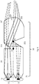
- the front-lighting system comprises a light source 10 and an integrated lens 20, wherein light emitted by the light source 10 is incident into the integrated lens 20, guided therethrough and then redirected out from it, for example redirected towards a road in front of the vehicle.
- the light source 10 can comprise two sub-light sources, for example, a first sub-light source 11 and a second sub-light source 12 as shown respectively at a lower position and an upper position in the figure.
- the first sub-light source 11 is configured to provide a low light beam of the front-lighting system.
- the second sub-light source 12 can be configured to provide a high light beam of the front-lighting system.
- the first sub-light source 11 located at a lower position within the front-lighting system will emit light (such as the low light beam) onto a lower part of the integrated lens 20, while light from the second sub-light source 12 (such as the high light beam) will be incident onto an upper part of the integrated lens 20.
- the two light beams, i.e. , the low light beam and the high light beam are guaranteed to be separated from each other within the front-lighting system. This helps to provide flexibility in for example the individual beam shaping of both the low and high light beams.
- the single, integrated lens 20 of the front-lighting system consists of three parts, i.e. , the first one being its light entrance surface 21, the second one being its light exit surface 23, and the third one being its light guiding portion 22 which is sandwiched between the light entrance surface 21 and the light exit surface 23.
- the first and high light beams emitted respectively by the first and second sub-light sources 11, 12 are incident firstly onto the light entrance surface 21 of the integrated lens 20, redirected thereby, and then guided along the light guiding portion 22 of the integrated lens 20, such as by means of reflection and/or refraction at outer surfaces of the light guiding portion 22.
- both of the low light beam and the high light beam arrive at the light exit surface 23, where they are refracted out from the integrated lens 20 towards for example a road in front of the vehicle.
- the light entrance surface 21 may be configured as a light refractive surface, which is to receive light, both the low and high light beams, from the light source 10 and redirects them respectively as refracted light beams into the light guiding portion 22.
- the low light beam coming out from the first sub-light source 11 is refracted by a lower part of the light entrance surface 21, and then incident also into a lower part of the light guiding portion 22.
- the high light beam coming out from the second sub-light source 12 is refracted by an upper part of the light entrance surface 21, and then incident also into an upper part of the light guiding portion 22.
- the two light beams i.e. , the low and high light beams, are separated in a way within the integrated lens 22, so that while propagating and being guided there along, mutual effects between the two are avoided greatly.
- the integrated lens 20 further comprises a light projecting surface as its light exit surface 23.
- the light projecting surface may be configured to receive light, such as the low and high light beams, from the light guiding portion 22 of the integrated lens 20, and then project them out towards a road in front of the vehicle.
- the low light beam can be projected by the light projecting surface at a lower vertical position in front of the vehicle, rendering it possible to provide both of the low and high light functions by the same front-lighting system.
- the specific forms may comprise for example a light refractive surface, a Fresnel surface, and so on.
- the light guiding portion 22 of the integrated lens 20 comprises at least two notches, a first notch 221 and a second notch 222 as seen in Fig. 1 .
- the integrated lens 20 can be designed in a shape of a hexahedron, wherein the light entrance surface 21 and the light exit surface 23 are the left and right sides of the hexahedron respectively.
- the first and second notches 221, 222 can be formed for example on the upper and lower sides of the hexahedron respectively.
- the first notch 221 can be provided on the front side of the hexahedron, while the second notch 222 can be provided on the back side of the hexahedron. In this way, it is ensured that the first notch 221 is located at an opposite position as compared with the second notch 222.
- the low light beam coming from the first sub-light source 11 is emitted firstly onto a lower part of the light entrance surface 21 and refracted thereby as a lower refracted light beam, thus propagating for example rightwards until being incident onto the first notch 221.
- Fig. 1 the low light beam coming from the first sub-light source 11 is emitted firstly onto a lower part of the light entrance surface 21 and refracted thereby as a lower refracted light beam, thus propagating for example rightwards until being incident onto the first notch 221.
- each of the first notch 221 and the second notch 222 consists of two facets being carved into the light guiding portion 22 and enclosing a certain angle therebetween.
- the low light beam is incident firstly onto a first facet 2210 of the first notch 221 (such as the left one in the figure), reflected thereby towards for example an upward direction, and then incident onto a second facet 2220 of the second notch 222 (such as the right one which is especially in parallel to the first, left facet 2210 of the first notch 221, and reflected thereby towards for example a rightward direction.
- the low light beam continues its rightwards propagation or guidance within the remaining part of the light guiding portion 22, until being incident onto an upper part of the light exit surface 23, where it is projected out from the integrated lens 20 for example towards a lower right direction.
- reflections of the low light beam by the first notch 221 and the second notch 222 can be either total reflections or partial reflections.
- the first facet 2210 of the first notch 221 can be either transparent or coated, and so does the second facet 2220 of the second notch 222.
- total reflection is preferred according to the present invention.
- the high light beam is emitted onto an upper part of the light entrance surface 21, and refracted thereby as an upper refracted light beam propagating for example rightwards until being incident onto a left facet of the second notch 222.
- the high light beam is firstly incident onto the left facet and refracted thereby.
- the incoming high light beam arrives at the right facet 2220 of the second notch 222, and refracted further towards a lower right direction, thus being incident onto a lower part of the light exit surface 23 and refracted there out from the integrated lens 20 for example towards an upper right direction.
- the low light beam coming from the first sub-light source 11 may be not reflected entirely by the first notch 22, especially by the left facet 2210 thereof in the figure.
- the low light beam has one of its uppermost light rays (indicated by a dashed ellipse in Fig. 1 ) to be incident at an uppermost position of the first notch 221 or its left facet 2210, leading to the remaining uppermost light rays at an even higher position ( i.e. , above the light ray indicated by a dashed ellipse in Fig.
- the first notch 221 of the integrated lens 20 helps to form an upper edge profile of the low light beam.
- this upper edge profile of the low light beam constitutes a final cut-off profile at its upper edge.
- the low light beam and the high light beam can be provided for example by different parts of the single system, but also a clear cut-off profile can be formed automatically within the low light beam such as by a suitable configuration of the first notch 221 on the light guiding portion 22 of the integrated lens 20.
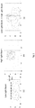
- Fig. 2 Simulated distributions of light intensity projected by the front-lighting system of Fig. 1 are shown in Fig. 2 , where the distribution of light intensity is illustrated in the first plot (a) only for the low light beam, the distribution of light intensity is illustrated in the second plot (b) only for the high light beam, and the combined distribution of light intensity is illustrated in the third plot (c) for both the low and high light beams.
- the low light beam and the high light beam can be both obtained by the same front-lighting system of Fig. 1 comprising for example a light source 10 and an integrated lens 20, where the high light beam is projected at an upper vertical position as compared with the low light beam, making it suitable in practical applications.
- a clear cut-off line is formed of the final low light beam, which requires no extra component or element added into the front-lighting system, but rather a suitable configuration of the first notch on the light guiding portion of the integrated lens. In this way, a simplified structure is guaranteed of the above proposed front-lighting system, which contributes also to a lower complexity in optics and a reduced cost in manufacture.
- a front-lighting system according to another embodiment of the present invention is illustrated in a cross section view.
- the front-lighting system shown in Fig. 3 has basically a similar structure as that shown in Fig. 1 , and thus the same or similar reference numerals are used to indicate the same or similar elements or components. That is, the front-lighting system of Fig. 3 comprises also a light source 10 and an integrated lens 20, wherein, as similar to Fig. 1 , the light source 10 comprises the first and second sub-light sources 11, 12, and the integrated lens 20 comprises a light entrance surface 21', a light guiding portion 22 and a light exit surface 23.
- the light entrance surface 21' which is configured especially to be a light collimating surface in Fig. 3 .
- light coming from the light source 10 is incident onto the light collimating surface of the integrated lens 20.
- the low light beam coming from the first sub-light source 11 and the high light beam coming from the second sub-light source 12 are incident respectively at the lower and upper parts of the light entrance surface 21' which is now light collimating.
- the low light beam from the first sub-light source 11 is refracted as a lower collimated light beam propagating for example horizontally towards the first notch 221 provided on the light guiding portion 22 (such as on its lower surface) of the integrated lens 20, while the high light beam from the second sub-light source 12 is refracted as an upper collimated light beam also propagating for example horizontally towards the second notch 222 provided also on the light guiding portion 22 (such as on its upper surface) of the integrated lens 20.
- the low light beam is reflected successively by the first and second facets 2210, 2220 as indicated above, thus arriving at the light exit surface 23 (such as its upper portion) of the integrated lens 20.
- the high light beam it is refracted for example by the left facet and the right facet 2220 of the second notch 222 successively (especially just passing through the left face of the second notch 222 due to a normal incidence, and then being refracted by the right facet 2220 of the second notch 222), thus arriving at the light exit surface 23 (such as its lower portion) of the integrated lens 20.
- the light exit surface 23 both of the low and high light beams are projected out from the integrated lens 20 for example towards a road in front of the vehicle, just as the embodiment shown in Fig. 1 .
- the light entrance surface 21 being light refractive in Fig. 1 and the light entrance surface 21' being light collimating in Fig. 3 are both shown to consist of several sloped facets having different sloped angles and bordered end to end, the present invention is not limited only to it. Any other suitable shape of the light entrance surface 21, 21' can be used, as long as the incoming low and high light beams are refracted properly into the light guiding portion 22 of the integrated lens 20.
- Fig. 4 shows another front-lighting system in a cross section view according to an embodiment of the present invention.
- the basic structure of the front-lighting system shown in Fig. 4 is similar to that shown in Fig. 1 , and thus the same reference numerals are used to indicate the same components. That is, there are also a light source 10 (including a first sub-light source 11 and a second sub-light source 12) and an integrated lens 20 (comprising a light entrance surface 21, a light guiding portion 22 and a light exit surface 23) existing within the front-lighting system of Fig. 4 , wherein a first notch 221 and a second notch 222 are formed as well on the light guiding portion 22.
- a light source 10 including a first sub-light source 11 and a second sub-light source 12
- an integrated lens 20 comprising a light entrance surface 21, a light guiding portion 22 and a light exit surface 23
- the front-lighting system of Fig. 4 now comprises an extra component, i.e. , a projection lens 30 located at an optically downstream position as compared with the light source 10 and the integrated lens 20.
- the light exit surface 23 of the integrated lens 20 is configured to be a flat surface, not like the light projecting one which is for example curved in Fig. 1 . More preferably, the flat, light exit surface 23 is positioned further at a focal point F of the projection lens 30, thus rendering the incoming low and high light beams to be projected into the far field, for example towards a road in front of the vehicle.
- a projection lens 30 located at an optically downstream position as compared with the light source 10 and the integrated lens 20.
- the light exit surface 23 of the integrated lens 20 is configured to be a flat surface, not like the light projecting one which is for example curved in Fig. 1 . More preferably, the flat, light exit surface 23 is positioned further at a focal point F of the projection lens 30, thus rendering the incoming low and high light beams
- the low light beam incident at an upper portion of the light exit surface 23 is refracted onto an upper portion of the projection lens 30, and projected thereby towards a lower right direction in front of the vehicle.
- the high light beam incident at a lower portion of the light exit surface 23 is refracted onto a lower portion of the projection lens 30, and projected thereby towards an upper right direction in front of the vehicle.
- the low and high light beams are projected respectively by the projection lens 30 towards a lower vertical position and an upper vertical position in front of the vehicle, making the above proposed front-lighting system suitable for use in automotive lighting.
- the additionally introduced projection lens 30 comprises further two parts, i.e. , a first sub-projection lens 301 and a second sub-projection lens 302 as shown in Fig. 5 , wherein Fig. 5 illustrates a front-lighting system in a cross section view according to another embodiment of the present invention.
- the front-lighting system shown in Fig. 5 is in a similar configuration as compared with that of Fig. 4 , except for the only difference that the projection lens 30 consists of two parts, i.e. , a first sub-projection lens 301 and a second sub-projection lens 302 stacked especially up and down in the figure.
- the upper, first sub-projection lens 301 is configured to receive and redirect the incoming low light beam from the integrated lens 20, while the lower, second sub-projection lens 302 is configured to receive and redirect the incoming high light beam from the integrated lens 20.
- the first notch 221 and the second notch 222 are positioned respectively at the focal points F1, F2 of the two sub-projection lenses 301, 302 in object space, thus rendering an optimized projection effect for the low and high light beams by the respective first and second sub-projections lenses 301, 302. It should be noted herein that although the two sub-projections lenses 301, 302 are shown in Fig.
- the first sub-projection lens 301 can occupy only the upper one-third part of the whole projection lens 30, while the second sub-projection lens 302 occupies the remaining lower part, meaning that the separation line between the two sub-projection lenses 301, 302 is located above, not at the optical axis of the whole front-lighting system.
- a reverse disposition applies as well, i.e.
- the first sub-projection lens 301 occupies the upper two-thirds part of the whole projection lens 30, while the second sub-projection lens 302 occupies the remaining one-third part, meaning that the separation line between the two sub-projection lenses 301, 302 is located below the optical axis of the whole system.
- a front-lighting system according to another embodiment of the present invention is illustrated in a cross section view, wherein the same or similar reference numerals are used to indicate the same or similar elements or components as in Fig. 1 .
- the front-lighting system shown in Fig. 6 comprises also a light source 10 (consisting of a first sub-light source 11 and a second sub-light source 12) and an integrated lens 20 (comprising a light entrance surface 21, a light guiding portion 22 and a light exit surface 23'), wherein a first notch 221 and a second notch 222 are formed as well on the light guiding portion 22.
- a light source 10 consisting of a first sub-light source 11 and a second sub-light source 12
- an integrated lens 20 comprising a light entrance surface 21, a light guiding portion 22 and a light exit surface 23'
- a first notch 221 and a second notch 222 are formed as well on the light guiding portion 22.
- the light exit surface 23' is configured to comprise two sub-surfaces, i.e. , a first sub-surface 231 and a second sub-surface 232 as shown in Fig. 6 .
- the first sub-surface 231 and the second sub-surface 232 are designed in such a way that projections of the two incident light beams, i.e. , the low and high light beams, are enabled properly towards a road in front of the vehicle.
- the two sub-surfaces 231, 232 of the light exit surface 23' are stacked up and down in the front-lighting system, rendering the low light beam to be incident onto the upper, first sub-surface 231 while the high light beam to be incident onto the lower, second sub-surface 232.
- the low light beam is projected or redirected by the first sub-surface 231 for example towards a lower right direction
- the high light beam is projected or redirected by the second sub-surface 232 for example towards an upper right direction, contributing together to the combined beam pattern comprising an upper high beam pattern and a lower low beam pattern.
- the separation line between the two sub-surfaces 231, 232 of the light exit surface 23' is not limited only to be above the optical axis (indicated by a dashed horizontal line in the figure) of the whole system, like that shown in Fig. 6 .
- the two sub-surfaces 231, 232 of the light exit surface 23' can be separated also by a separation line located at or even below the optical axis (indicated by a dashed horizontal line in the figure) of the whole front-lighting system, and the present invention shall encompass all these alternatives within the scope thereof.
- the first notch 221 and the second notch 222 are positioned especially at the focal points F1', F2' of the two sub-surfaces 231, 232 of the light exit surface 23', such that proper projections of the low and high light beams are guaranteed into the far field so as to facilitate use in automotive lighting.
- front-lighting system as proposed by the present invention may comprise one or more light sources and correspondingly one or more integrated lenses.
- each light source is paired with a respective integrated lens, meaning that light emitted by each light source is incident into a corresponding integrated lens and then refracted therefrom towards a road in front of the vehicle.
- the present invention is never restricted only to this special embodiment. Having benefited from the teaching of the present invention, those skilled in the art shall easily conceive that more than two notches can be formed as well.
- the light guiding portion of the integrated lens can be provided further with a third notch and a fourth notch opposite to the third notch.
- the third notch can be formed on the lower surface of the light guiding portion as well, but displaced by a small distance with respect to the first notch in a direction parallel to the extending plane of the lower surface and perpendicular to the optical axis of the whole system, i.e. , in a direction perpendicular to the cross section view in the figure.
- the first and third notches are formed in a line on the lower surface of the light guiding portion.
- a similar configuration applies to the second and fourth notches as well.
- a rod light source with its main axis perpendicular to the cross section view in the figure such as a rod first sub-light source and a rod second sub-light source, can be used, so that a larger and also stronger light output is obtained to provide front-lighting for the vehicle.
- one or more further pairs of notches such as a fifth one and a sixth one, can be used as well according to different practical applications.
Landscapes
- Engineering & Computer Science (AREA)
- General Engineering & Computer Science (AREA)
- Physics & Mathematics (AREA)
- Microelectronics & Electronic Packaging (AREA)
- Optics & Photonics (AREA)
- Non-Portable Lighting Devices Or Systems Thereof (AREA)
Abstract
Description
- The present invention relates to the field of automotive front-lighting, and particularly to a front-lighting system for a vehicle.
- Bi-function Poly-Ellipsoidal System (PES) solution for a headlamp has been widely used in automotive lighting today. Generally, in Bi-function PES solution, the low light beam function and the high light beam function are provided respectively by two individual modules, i.e., the low beam module and the high beam module. For example, the low beam module may be composed of a low beam light source and a low beam optics, which comprises such as a reflector and a light redirecting lens. In a similar way, the high beam module may be composed of a high beam light source and a high beam optics comprising such as another reflector and another light redirecting lens. Further, in this case, the low light beam and the high light beam can be both projected for example by a single projection lens towards a road in front of a vehicle, which projection lens is located at an optically downstream position as compared with the low beam module and the high beam module. Alternatively, the low light beam and the high light beam can be also projected separately in front of the vehicle, i.e., by a low beam projection lens and a high beam projection lens respectively. As can be seen, the complex structural constitution of conventional Bi-function PES solution tends to give a front-lighting system comprising too many optical parts used for different purposes, such as the two individual modules to provide the high light beam function and the low light beam function respectively. Although approaches have been proposed as well to use only one light redirecting lens for both the low light beam function and the high light beam function, two or more than two surfaces (convex or flat) or parts of the single light redirecting lens are needed so as to receive and redirect the low and high light beams respectively, such that requirements of the low and high light beams are both satisfied. Again, this provides the single light redirecting lens with a complex construction, making it complicated and expensive to be manufactured.
-
EP3124854A1 relates to a lighting system for a motor vehicle comprising at least one primary optical device for emitting a light beam exhibiting a cut-off profile, the primary optical emission device comprising at least one light source and one single-piece primary optical member comprising an input surface suitable for receiving a light beam emitted by the light source, a ray interception surface configured to form the cut-off profile in the light beam received and an output surface for the light beam. -
EP3093557A1 relates to a lighting module for a motor vehicle headlight intended to produce a low beam having an at least partly oblique cut-off. The lighting module further comprises an additional lighting function making it possible to generate a high type beam, wherein the light sources of the two respective low and high beam functions are arranged in a vicinity of the focus of an optical portion of the module such that the lighting module remains compact. - The present invention provides a front-lighting system for a vehicle, so as to eliminate or at least alleviate one or more of the above mentioned disadvantages.
- According to an embodiment of the present invention, a front-lighting system is proposed for use in a vehicle. The front-lighting system comprises a light source and an integrated lens, wherein the integrated lens comprises a light entrance surface, a light exit surface, and a light guiding portion sandwiched between the light entrance surface and the light exit surface. Besides, the light source is configured to emit a first light beam and a second light beam onto the light entrance surface of the integrated lens. After being incident onto the light entrance surface, the first and second light beams are guided by the light guiding portion of the integrated lens towards the light exit surface. At the light exit surface, the first light beam and the second light beam are both redirected out from the integrated lens. Further, the light guiding portion also comprises at least a first notch and a second notch opposite to the first notch, wherein, while being guided, the first light beam undergoes an at least partial reflection successively by the first notch and the second notch, and the second light beam undergoes a refraction by the second notch.
- According to a preferable embodiment of the present invention, in the front-lighting system proposed above, the first light beam undergoes a total reflection successively by the first notch and the second notch, while it is guided by the light guiding portion of the integrated lens.
- Besides, according to an optional embodiment of the present invention, in the above described front-lighting system, the first light beam coming out from the light source exhibits a cut-off profile, for example a clear cut-off line in a vertical plane, which is formed by the first notch while the first light beam is guided along the light guiding portion of the integrated lens.
- Further optionally, in another optional embodiment of the present invention, the light source of the front-lighting system comprises specifically a first sub-light source and a second sub-light source. Especially, the first sub-light source is configured to emit the first light beam as a low light beam, and the second sub-light source is configured to emit the second light beam as a high light beam.
- As can be seen, in the front-lighting system proposed by the present invention for a vehicle, the low light beam and the high light beam are both emitted out from the light source, for example emitted by two sub-light sources separately. Then, the low and high light beams are both permitted to be incident into the integrated lens, i.e., into the single lens element, where they are guided until being redirected out therefrom and projected for example towards a road in front of the vehicle. In this case, it is guaranteed that the low light beam function and the high light beam function are provided by a single optical module, i.e., comprising the light source and the only integrated lens, which helps to give a much simpler and more compact front-lighting system for a vehicle.
- Besides, according to the above proposed front-lighting system of the present invention, while being guided along the light guiding portion of the integrated lens, the low light beam and the high light beam undergo different optical processes. To this end, the light guiding portion of the integrated lens is provided with at least two notches which are opposite to each other, the first notch and the second notch. In this case, the first light beam, for example, the low light beam, is at least partially reflected (preferably, totally reflected) successively by the first notch and the second notch, i.e., reflected firstly by the first notch and then by the second notch, while it is guided through the light guiding portion of the integrated lens. More preferably, during such guiding process of the first, low light beam, the first notch is configured further to help forming a cut-off profile within the first, low light beam. With respect to the second light beam, for example the high light beam, it is only refracted by the second notch while being guided along the light guiding portion of the integrated lens. In this way, not only a more simplified and compact structure is provided of the above proposed front-lighting system, but also a cut-off profile (such as a clear cut-off line in a vertical plane) is generated within the first, low light beam, helping to obtain finally a simple and cost-effective Bi-function PES solution suitable for use in a vehicle.
- According to a practical implementation, in the front-lighting system proposed by an embodiment of the present invention, the light guiding portion of the integrated lens comprises at least a first surface and a second surface opposite to the first surface, wherein both of the first surface and the second surface extend between the light entrance surface and the light exit surface. For example, if the integrated lens is shaped in hexahedron, the light entrance surface and the light exit surface can be the left and right sides of the hexahedron respectively, while the first and second surfaces can be respectively the upper and lower sides of the hexahedron. Apparently, the example of hexahedron is merely provided herein to illustrate, rather than limit the present invention, and any other suitable shape, such as cylinder, can be used for the integrated lens. Further optionally, in an example instance of the above embodiment, the first notch is provided on the first surface, and the second notch is provided on the second surface, or vice versa. More preferably, in the above mentioned embodiment, the first notch comprises a first facet, and the second notch comprises a second facet parallel to the first facet. Taking still the above hexahedron-shaped integrated lens as an example, the first sub-light source providing the first, low light beam can be positioned, as seen when installed in the vehicle, at a lower position as compared with the second sub-light source providing the second, high light beam, rendering the first, low light beam to be incident onto a lower position at the light entrance surface than the second, high light beam. In this case, after being redirected by the light entrance surface, the first, low light beam can be incident onto the first facet of the first notch in the first place, and then onto the second facet of the second notch. As mentioned above, the second facet is parallel to the first facet. Thus, the cut-off profile formed by the first facet within the first, low light beam is merely projected by the second facet of the second notch, leading to the cut-off profile projected clearly in the final low beam pattern.
- According to other practical implementations, the front-lighting system proposed by an embodiment of the present invention further comprises a projection lens, which is configured to receive the first light beam and the second light beam from the integrated lens, and then redirect them towards a road in front of a vehicle. Optionally, in the above mentioned embodiment of the present invention, the light exit surface of the integrated lens is positioned preferably at a focal point of the projection lens. In this way, the first and second light beams, coming out from the integrated lens, are projected by the projection lens into the far field, i.e., towards the road in front of the vehicle.
- Besides, in the above proposed front-lighting system, the projection lens further comprises a first sub-projection lens and a second sub-projection lens. To be specific, the first sub-projection lens is used to receive and redirect the first light beam towards the road in front of the vehicle. In a similar way, the second sub-projection lens is used to receive and redirect the second light beam towards the road in front of the vehicle. This means that the first and second light beams are projected separately by different portions of the projection lens, helping to give more freedom in design of the final first and second beam patterns as projected towards the road in front of the vehicle, such as in design of intensity distribution and/or pattern shape. Further preferably, in the above embodiment, the first notch can be positioned at a focal point of the first sub-projection lens, while the second notch can be positioned at a focal point of the second sub-projection lens, so that the two light beams (i.e., the first and second light beams) are projected properly by their own sub-projection lenses.
- According to a different practical implementation, in the above front-lighting system proposed by an embodiment of the present invention, the light exit surface of the integrated lens comprises a light projecting surface. Especially, the light projecting surface is configured to receive the first light beam and the second light beam from the light guiding portion, and then redirect them towards a road in front of a vehicle. For example, the light projecting surface can be formed by a light refractive surface or a Fresnel surface, whose purpose is to project both of the first light beam and the second light beam out from the integrated lens and then into the far field, for example, towards the road in front of the vehicle. In this case, no separate projection element, such as the above mentioned projection lens, is required to redirect the first and second light beams, leading to a front-lighting system with a simplified structure and a smaller number of constitutive elements.
- Further optionally, according to an example instance of the above embodiment, the light projecting surface of the integrated lens comprises a first sub-surface and a second sub-surface. To be specific, the first sub-surface is configured to receive and redirect the first light beam, while the second sub-surface is to receive and redirect the second light beam. In other words, the light projecting surface of the integrated lens is composed of two separate sub-surfaces, which are used respectively to receive and redirect the two light beams from the light guiding portion of the integrated lens. Again, as similar to the two sub-projection lenses of the above mentioned projection lens, providing the light projecting surface of the integrated lens with two separate sub-surfaces used respectively for the two incident light beams is beneficial to give more freedom in design of the two light beams themselves, such as in intensity distribution and/or pattern shape. More preferably, in an example instance of the above described embodiment, the first notch of the integrated lens is positioned at a focal point of the first sub-surface, and the second notch of the integrated lens is positioned at a focal point of the second sub-surface, helping to provide the first and second light beams with a proper projection towards the road in front of the vehicle.
- According to a different practical implementation, in the above front-lighting system proposed by an embodiment of the present invention, the light entrance surface of the integrated lens comprises a light refractive surface, more preferably a light collimating surface. Specifically, the light collimating surface of the integrated lens can be used to receive the first and second light beams from the light source, and then redirect both of them as collimated light beams into the light guiding portion. With regard to the general, light refractive surface (not a preferred, light collimating one), suitable degrees of refraction can be offered to the first and second light beams, so that they are incident into the guiding portion of the integrated lens at proper angles of incidence as desired. As specific examples, the light refractive surface of the integrated lens can be shaped into a convex or flat surface, such as a sphere, aspheric or a freeform surface.
- According to other practical implementations of the present invention, the above proposed front-lighting system also comprises one or more further light sources in an array, and one or more further integrated lenses in an array. Preferably, each further light source comprises a first sub-light source and a second sub-light source as well, wherein the first and second sub-light sources are configured to emit respectively a further first light beam and a further second light beam. Besides, each further integrated lens is configured to receive the further first light beam and the further second light beam from a respective one of the one or more further light sources. That is to say, in the front-lighting system proposed by the above embodiment, there is a plurality of light sources and correspondingly also a plurality of integrated lenses, both disposed in an array distribution. This means that the front-lighting system in this case is composed of multiple individual sub-systems, wherein each sub-system comprises a single light source and a single integrated lens, just as the system we mentioned for example in each of the above embodiments. In this way, not only a stronger light output can be obtained, but also flexibilities are enabled for example in design of the final light beam pattern in front of the vehicle, comprising specifically the first and second light beams as mentioned above.
- It will be appreciated by those skilled in the art that two or more of the above disclosed embodiments, implementations and/or aspects of the present invention may be combined in any way deemed useful. Different modifications and variations of the front-lighting system for a vehicle can be carried out by a person skilled in the art based on the disclosure of the present invention.
- These and other aspects of the present invention will be described in the following in more details, with reference to the appended drawings showing embodiments and forming a part of the present invention. In the drawings:
-
Fig. 1 schematically illustrates a front-lighting system for a vehicle in a cross section view according to an embodiment of the present invention, wherein the front-lighting system comprises an integrated lens provided with a light refractive surface as its light entrance surface and a light projecting surface as its light exit surface; -
Fig. 2 schematically illustrates the simulated distributions of light intensity projected by the front-lighting system ofFig. 1 towards a road in front of the vehicle, wherein the low beam distribution, the high beam distribution, and the combined beam distribution comprising both of the previous two are shown respectively in plots (a), (b) and (c); -
Fig. 3 schematically illustrates a front-lighting system for a vehicle in a cross section view according to an embodiment of the present invention, wherein the front-lighting system comprises an integrated lens provided with a light collimating surface as its light entrance surface and also provided with two notches; -
Fig. 4 schematically illustrates a front-lighting system for a vehicle in a cross section view according to an embodiment of the present invention, wherein a single additional projection lens is also included in the front-lighting system; -
Fig. 5 schematically illustrates a front-lighting system for a vehicle in a cross section view according to an embodiment of the present invention, wherein two sub-projection lenses are included in the front-lighting system; and -
Fig. 6 schematically illustrates a front-lighting system for a vehicle in a cross section view according to an embodiment of the present invention, wherein the front-lighting system comprises an integrated lens provided with two light projecting, sub-surfaces as its light exit surface. - While the present invention is susceptible of embodiments in many different forms, there is shown in the drawings and will be described in detail herein only one or more specific embodiments, with the understanding that the present description is to be considered only as exemplary of the basic principle of the present invention and not intended to limit the present invention merely to the specific embodiments shown and described herein.
- It should be noted that various components in different figures are not drawn to scale. Besides, relative positions between individual elements shown in the figures are only used to illustrate the basic principle of the present invention and should not be considered to limit the scope of the present invention.
- With reference to
Fig. 1 , a front-lighting system is proposed for use in a vehicle. As shown inFig. 1 , the front-lighting system comprises alight source 10 and anintegrated lens 20, wherein light emitted by thelight source 10 is incident into theintegrated lens 20, guided therethrough and then redirected out from it, for example redirected towards a road in front of the vehicle. To be specific, thelight source 10 can comprise two sub-light sources, for example, a firstsub-light source 11 and a secondsub-light source 12 as shown respectively at a lower position and an upper position in the figure. According to an example embodiment of the present invention, the firstsub-light source 11 is configured to provide a low light beam of the front-lighting system. In a similar way, the secondsub-light source 12 can be configured to provide a high light beam of the front-lighting system. As seen inFig. 1 , the firstsub-light source 11 located at a lower position within the front-lighting system will emit light (such as the low light beam) onto a lower part of theintegrated lens 20, while light from the second sub-light source 12 (such as the high light beam) will be incident onto an upper part of theintegrated lens 20. In this way, the two light beams, i.e., the low light beam and the high light beam are guaranteed to be separated from each other within the front-lighting system. This helps to provide flexibility in for example the individual beam shaping of both the low and high light beams. - With continued reference to
Fig. 1 , the single, integratedlens 20 of the front-lighting system consists of three parts, i.e., the first one being itslight entrance surface 21, the second one being itslight exit surface 23, and the third one being itslight guiding portion 22 which is sandwiched between thelight entrance surface 21 and thelight exit surface 23. From the perspective of light propagation, light coming from thelight source 10, for example, the low and high light beams emitted respectively by the first and secondsub-light sources light entrance surface 21 of theintegrated lens 20, redirected thereby, and then guided along thelight guiding portion 22 of theintegrated lens 20, such as by means of reflection and/or refraction at outer surfaces of thelight guiding portion 22. Finally, both of the low light beam and the high light beam arrive at thelight exit surface 23, where they are refracted out from the integratedlens 20 towards for example a road in front of the vehicle. As shown inFig. 1 , in theintegrated lens 20, thelight entrance surface 21 may be configured as a light refractive surface, which is to receive light, both the low and high light beams, from thelight source 10 and redirects them respectively as refracted light beams into thelight guiding portion 22. For example, as clearly visible inFig. 1 , the low light beam coming out from the firstsub-light source 11 is refracted by a lower part of thelight entrance surface 21, and then incident also into a lower part of thelight guiding portion 22. Similarly, the high light beam coming out from the secondsub-light source 12 is refracted by an upper part of thelight entrance surface 21, and then incident also into an upper part of thelight guiding portion 22. Obviously, the two light beams, i.e., the low and high light beams, are separated in a way within the integratedlens 22, so that while propagating and being guided there along, mutual effects between the two are avoided greatly. - Additionally, according to an embodiment of the present invention, the
integrated lens 20 further comprises a light projecting surface as itslight exit surface 23. Specifically, the light projecting surface may be configured to receive light, such as the low and high light beams, from thelight guiding portion 22 of theintegrated lens 20, and then project them out towards a road in front of the vehicle. For example, as compared with the high light beam, the low light beam can be projected by the light projecting surface at a lower vertical position in front of the vehicle, rendering it possible to provide both of the low and high light functions by the same front-lighting system. According to practical implementations, if a light projecting surface is chosen as thelight exit surface 23, the specific forms may comprise for example a light refractive surface, a Fresnel surface, and so on. - Furthermore the
light guiding portion 22 of theintegrated lens 20 comprises at least two notches, afirst notch 221 and asecond notch 222 as seen inFig. 1 . Exemplarily, according to an instance of the above mentioned embodiment, theintegrated lens 20 can be designed in a shape of a hexahedron, wherein thelight entrance surface 21 and thelight exit surface 23 are the left and right sides of the hexahedron respectively. In this case, the first andsecond notches first notch 221 can be provided on the front side of the hexahedron, while thesecond notch 222 can be provided on the back side of the hexahedron. In this way, it is ensured that thefirst notch 221 is located at an opposite position as compared with thesecond notch 222. With further reference toFig. 1 , the low light beam coming from the firstsub-light source 11 is emitted firstly onto a lower part of thelight entrance surface 21 and refracted thereby as a lower refracted light beam, thus propagating for example rightwards until being incident onto thefirst notch 221. As shown schematically inFig. 1 , each of thefirst notch 221 and thesecond notch 222 consists of two facets being carved into thelight guiding portion 22 and enclosing a certain angle therebetween. In this case, the low light beam is incident firstly onto afirst facet 2210 of the first notch 221 (such as the left one in the figure), reflected thereby towards for example an upward direction, and then incident onto asecond facet 2220 of the second notch 222 (such as the right one which is especially in parallel to the first,left facet 2210 of thefirst notch 221, and reflected thereby towards for example a rightward direction. After that, the low light beam continues its rightwards propagation or guidance within the remaining part of thelight guiding portion 22, until being incident onto an upper part of thelight exit surface 23, where it is projected out from the integratedlens 20 for example towards a lower right direction. It should be noted herein that reflections of the low light beam by thefirst notch 221 and thesecond notch 222 can be either total reflections or partial reflections. For example, thefirst facet 2210 of thefirst notch 221 can be either transparent or coated, and so does thesecond facet 2220 of thesecond notch 222. However, considering a maximized usage or a reduced loss of light, total reflection is preferred according to the present invention. - Turning to the high light beam, as indicated above and shown also in
Fig. 1 , it is emitted onto an upper part of thelight entrance surface 21, and refracted thereby as an upper refracted light beam propagating for example rightwards until being incident onto a left facet of thesecond notch 222. At thesecond notch 222 comprising for example a left facet and a right facet, the high light beam is firstly incident onto the left facet and refracted thereby. After that, the incoming high light beam arrives at theright facet 2220 of thesecond notch 222, and refracted further towards a lower right direction, thus being incident onto a lower part of thelight exit surface 23 and refracted there out from the integratedlens 20 for example towards an upper right direction. - With continued reference to
Fig. 1 , due to the special design of thefirst notch 221, such as its recess depth within thelight guiding portion 22 or the slope angle of itsleft facet 2210, the low light beam coming from the firstsub-light source 11 may be not reflected entirely by thefirst notch 22, especially by theleft facet 2210 thereof in the figure. For example, the low light beam has one of its uppermost light rays (indicated by a dashed ellipse inFig. 1 ) to be incident at an uppermost position of thefirst notch 221 or itsleft facet 2210, leading to the remaining uppermost light rays at an even higher position (i.e., above the light ray indicated by a dashed ellipse inFig. 1 ) of the low light beam to be lost elsewhere within the system, thus making no contribution to the final low light beam. This means that thefirst notch 221 of theintegrated lens 20, for example, the uppermost peak thereof, helps to form an upper edge profile of the low light beam. After several times of subsequent projection, such as by thesecond notch 222 and thelight exit surface 23, this upper edge profile of the low light beam constitutes a final cut-off profile at its upper edge. In other words, according to the front-lighting system proposed by the present invention, not only the low light beam and the high light beam can be provided for example by different parts of the single system, but also a clear cut-off profile can be formed automatically within the low light beam such as by a suitable configuration of thefirst notch 221 on thelight guiding portion 22 of theintegrated lens 20. - Simulated distributions of light intensity projected by the front-lighting system of
Fig. 1 are shown inFig. 2 , where the distribution of light intensity is illustrated in the first plot (a) only for the low light beam, the distribution of light intensity is illustrated in the second plot (b) only for the high light beam, and the combined distribution of light intensity is illustrated in the third plot (c) for both the low and high light beams. As can be seen, the low light beam and the high light beam can be both obtained by the same front-lighting system ofFig. 1 comprising for example alight source 10 and anintegrated lens 20, where the high light beam is projected at an upper vertical position as compared with the low light beam, making it suitable in practical applications. Also, as seen in the simulated results ofFig. 2 , especially in the first plot (a), a clear cut-off line is formed of the final low light beam, which requires no extra component or element added into the front-lighting system, but rather a suitable configuration of the first notch on the light guiding portion of the integrated lens. In this way, a simplified structure is guaranteed of the above proposed front-lighting system, which contributes also to a lower complexity in optics and a reduced cost in manufacture. - With reference to
Fig. 3 , a front-lighting system according to another embodiment of the present invention is illustrated in a cross section view. The front-lighting system shown inFig. 3 has basically a similar structure as that shown inFig. 1 , and thus the same or similar reference numerals are used to indicate the same or similar elements or components. That is, the front-lighting system ofFig. 3 comprises also alight source 10 and anintegrated lens 20, wherein, as similar toFig. 1 , thelight source 10 comprises the first and secondsub-light sources integrated lens 20 comprises a light entrance surface 21', alight guiding portion 22 and alight exit surface 23. The difference betweenFig. 3 andFig. 1 lies in the light entrance surface 21', which is configured especially to be a light collimating surface inFig. 3 . In this case, light coming from thelight source 10 is incident onto the light collimating surface of theintegrated lens 20. For example, the low light beam coming from the firstsub-light source 11 and the high light beam coming from the secondsub-light source 12 are incident respectively at the lower and upper parts of the light entrance surface 21' which is now light collimating. After that, the low light beam from the firstsub-light source 11 is refracted as a lower collimated light beam propagating for example horizontally towards thefirst notch 221 provided on the light guiding portion 22 (such as on its lower surface) of theintegrated lens 20, while the high light beam from the secondsub-light source 12 is refracted as an upper collimated light beam also propagating for example horizontally towards thesecond notch 222 provided also on the light guiding portion 22 (such as on its upper surface) of theintegrated lens 20. At the twonotches second facets integrated lens 20. As for the high light beam, it is refracted for example by the left facet and theright facet 2220 of thesecond notch 222 successively (especially just passing through the left face of thesecond notch 222 due to a normal incidence, and then being refracted by theright facet 2220 of the second notch 222), thus arriving at the light exit surface 23 (such as its lower portion) of theintegrated lens 20. In the end, at thelight exit surface 23, both of the low and high light beams are projected out from the integratedlens 20 for example towards a road in front of the vehicle, just as the embodiment shown inFig. 1 . - It should be noted herein that although the
light entrance surface 21 being light refractive inFig. 1 and the light entrance surface 21' being light collimating inFig. 3 are both shown to consist of several sloped facets having different sloped angles and bordered end to end, the present invention is not limited only to it. Any other suitable shape of thelight entrance surface 21, 21' can be used, as long as the incoming low and high light beams are refracted properly into thelight guiding portion 22 of theintegrated lens 20. -
Fig. 4 shows another front-lighting system in a cross section view according to an embodiment of the present invention. The basic structure of the front-lighting system shown inFig. 4 is similar to that shown inFig. 1 , and thus the same reference numerals are used to indicate the same components. That is, there are also a light source 10 (including a firstsub-light source 11 and a second sub-light source 12) and an integrated lens 20 (comprising alight entrance surface 21, alight guiding portion 22 and a light exit surface 23) existing within the front-lighting system ofFig. 4 , wherein afirst notch 221 and asecond notch 222 are formed as well on thelight guiding portion 22. Different from the embodiment shown inFig. 1 , the front-lighting system ofFig. 4 now comprises an extra component, i.e., aprojection lens 30 located at an optically downstream position as compared with thelight source 10 and theintegrated lens 20. In this case, further optionally, thelight exit surface 23 of theintegrated lens 20 is configured to be a flat surface, not like the light projecting one which is for example curved inFig. 1 . More preferably, the flat,light exit surface 23 is positioned further at a focal point F of theprojection lens 30, thus rendering the incoming low and high light beams to be projected into the far field, for example towards a road in front of the vehicle. As seen inFig. 4 , the low light beam incident at an upper portion of thelight exit surface 23 is refracted onto an upper portion of theprojection lens 30, and projected thereby towards a lower right direction in front of the vehicle. In a similar way, the high light beam incident at a lower portion of thelight exit surface 23 is refracted onto a lower portion of theprojection lens 30, and projected thereby towards an upper right direction in front of the vehicle. In this way, the low and high light beams are projected respectively by theprojection lens 30 towards a lower vertical position and an upper vertical position in front of the vehicle, making the above proposed front-lighting system suitable for use in automotive lighting. - According to an example instance of the above embodiment, in the front-lighting system, the additionally introduced
projection lens 30 comprises further two parts, i.e., afirst sub-projection lens 301 and asecond sub-projection lens 302 as shown inFig. 5 , whereinFig. 5 illustrates a front-lighting system in a cross section view according to another embodiment of the present invention. The front-lighting system shown inFig. 5 is in a similar configuration as compared with that ofFig. 4 , except for the only difference that theprojection lens 30 consists of two parts, i.e., afirst sub-projection lens 301 and asecond sub-projection lens 302 stacked especially up and down in the figure. In this case, the upper, firstsub-projection lens 301 is configured to receive and redirect the incoming low light beam from the integratedlens 20, while the lower,second sub-projection lens 302 is configured to receive and redirect the incoming high light beam from the integratedlens 20. Preferably, thefirst notch 221 and thesecond notch 222 are positioned respectively at the focal points F1, F2 of the twosub-projection lenses sub-projections lenses sub-projections lenses Fig. 5 to be located at two sides of the optical axis (indicated by a dashed horizontal line in the figure) of the whole front-lighting system, this shall be never considered as any limitation to the present invention. As a matter of fact, according to different practical implementations, such as a distance between theprojection lens 30 and thelight exit surface 23 of theintegrated lens 20, thefirst sub-projection lens 301 can occupy only the upper one-third part of thewhole projection lens 30, while thesecond sub-projection lens 302 occupies the remaining lower part, meaning that the separation line between the twosub-projection lenses first sub-projection lens 301 occupies the upper two-thirds part of thewhole projection lens 30, while thesecond sub-projection lens 302 occupies the remaining one-third part, meaning that the separation line between the twosub-projection lenses - Turning to
Fig. 6 , a front-lighting system according to another embodiment of the present invention is illustrated in a cross section view, wherein the same or similar reference numerals are used to indicate the same or similar elements or components as inFig. 1 . In other words, the front-lighting system shown inFig. 6 comprises also a light source 10 (consisting of a firstsub-light source 11 and a second sub-light source 12) and an integrated lens 20 (comprising alight entrance surface 21, alight guiding portion 22 and a light exit surface 23'), wherein afirst notch 221 and asecond notch 222 are formed as well on thelight guiding portion 22. Different from the embodiment inFig. 1 , the front-lighting system ofFig. 6 comprises now a light exit surface 23' of theintegrated lens 20 provided with a special configuration. To be specific, the light exit surface 23' is configured to comprise two sub-surfaces, i.e., afirst sub-surface 231 and asecond sub-surface 232 as shown inFig. 6 . In this case, thefirst sub-surface 231 and thesecond sub-surface 232 are designed in such a way that projections of the two incident light beams, i.e., the low and high light beams, are enabled properly towards a road in front of the vehicle. For example, the twosub-surfaces first sub-surface 231 while the high light beam to be incident onto the lower,second sub-surface 232. In this way, the low light beam is projected or redirected by thefirst sub-surface 231 for example towards a lower right direction, while the high light beam is projected or redirected by thesecond sub-surface 232 for example towards an upper right direction, contributing together to the combined beam pattern comprising an upper high beam pattern and a lower low beam pattern. Again, as similar to the above embodiment inFig. 5 , the separation line between the twosub-surfaces Fig. 6 . Instead, according to different practical implementations, the twosub-surfaces first notch 221 and thesecond notch 222 are positioned especially at the focal points F1', F2' of the twosub-surfaces - It should be indicated that although all the above descriptions are merely directed to a front-light system comprising only one light source and one integrated lens, this shall be never considered as any limitation to the present invention. In fact, having benefited from the teaching of the present invention, a skilled person in the art shall easily understand that one or more duplicates, distributed especially in an array, of such light source and such integrated lens can be comprised within the proposed front-lighting system. This means that the front-lighting system as proposed by the present invention may comprise one or more light sources and correspondingly one or more integrated lenses. In this case, each light source is paired with a respective integrated lens, meaning that light emitted by each light source is incident into a corresponding integrated lens and then refracted therefrom towards a road in front of the vehicle. By introducing an array distribution of more than one light source and more than one integrated lens, not only an enhanced light output can be obtained by the above proposed front-lighting system, but also flexible design of the projected low and/or high beam pattern is possible, such as in pattern shape and/or intensity distribution.
- Also, it should be indicated that although only two notches are shown in the figures and formed oppositely for example on upper and lower surfaces of the light guiding portion of the integrated lens, the present invention is never restricted only to this special embodiment. Having benefited from the teaching of the present invention, those skilled in the art shall easily conceive that more than two notches can be formed as well. For example, in the above proposed front-lighting system, the light guiding portion of the integrated lens can be provided further with a third notch and a fourth notch opposite to the third notch. To be specific, the third notch can be formed on the lower surface of the light guiding portion as well, but displaced by a small distance with respect to the first notch in a direction parallel to the extending plane of the lower surface and perpendicular to the optical axis of the whole system, i.e., in a direction perpendicular to the cross section view in the figure. This means that the first and third notches are formed in a line on the lower surface of the light guiding portion. A similar configuration applies to the second and fourth notches as well. In this way, use of a light source with a larger size is facilitated, especially with a larger size in a direction parallel to the extending plane of the upper or lower surface and perpendicular to the optical axis of the whole system, i.e., in a direction perpendicular to the cross section view in the figure. For example, with the above additionally introduced third and fourth notches, a rod light source with its main axis perpendicular to the cross section view in the figure, such as a rod first sub-light source and a rod second sub-light source, can be used, so that a larger and also stronger light output is obtained to provide front-lighting for the vehicle. Thus, based on a similar consideration, one or more further pairs of notches, such as a fifth one and a sixth one, can be used as well according to different practical applications.
- It is important to note that light rays shown in the figures, only represent part, but not all, of the light rays within the whole front-lighting system. In fact, the light rays shown in all the figures are only used as representative examples for the purpose of illustrating the basic principle of the present invention, and clearly should not be read as exhaustive examples of all the light rays within the entire front-lighting system.
- It should also be noted that the above-mentioned embodiments illustrate rather than limit the present invention, and that those skilled in the art will be able to design many alternative embodiments without departing from the scope and spirit of the present invention. Although the present invention has been described in connection with some embodiments, it is not intended to be limited to the specific forms as set forth herein. Rather, the scope of the present invention is limited only by the accompanying claims. Additionally, although a feature may appear to be described in connection with particular embodiments, those skilled in the art would recognize that various features of the described embodiments may be combined in accordance with the present invention.
- Furthermore, although individual features may be included in different claims, these may possibly be advantageously combined, and the inclusion in different claims does not imply that a combination of features is not feasible and/or advantageous. In the claims, any reference signs placed between parentheses shall not be construed as limiting the claims. Use of the verb "comprise" and its conjugations does not exclude the presence of elements or steps other than those stated in a claim. The article "a" or "an" preceding an element does not exclude the presence of a plurality of such elements. Also, references to first, second etc. are merely to be considered as labels and do not imply or describe any ordering, sequence, relation or properties of the features prefixed by these terms. The mere fact that certain measures are recited in mutually different dependent claims does not indicate that a combination of these measures cannot be used to advantage.
-
- 10
- light source
- 11
- first sub-light source
- 12
- second sub-light source
- 20
- integrated lens
- 21, 21'
- light entrance surface
- 22
- light guiding portion
- 221
- first notch
- 2210
- first or left facet
- 222
- second notch
- 2220
- second or right facet
- 23, 23'
- light exit surface
- 30
- projection lens
- F
- focus point of projection lens
- 301
- first sub-projection lens
- F1
- focus point of first sub-projection lens
- 302
- second sub-projection lens
- F2
- focus point of second sub-projection lens
- 231
- first sub-surface
- 232
- second sub-surface
- F1'
- focus point of first sub-surface
- F2'
- focus point of second sub-surface
Claims (15)
- A front-lighting system for a vehicle, comprising:a light source (10), andan integrated lens (20) comprising a light entrance surface (21, 21'), a light exit surface (23, 23'), and a light guiding portion (22) sandwiched between the light entrance surface (21, 21') and the light exit surface (23, 23'), whereinthe light source (10) is configured to emit a first light beam and a second light beam onto the light entrance surface (21, 21'),the light guiding portion (22) is configured to receive the first light beam and the second light beam from the light entrance surface (21, 21'), and guide them towards the light exit surface (23, 23'), where the first light beam and the second light beam are both redirected out from the integrated lens (20), andthe light guiding portion (22) comprises at least a first notch (221) and a second notch (222) opposite to the first notch (221), wherein, while being guided, the first light beam undergoes an at least partial reflection successively by the first notch (221) and the second notch (222), and the second light beam undergoes a refraction by the second notch (222).
- The front-lighting system according to claim 1, wherein
while being guided, the first light beam undergoes a total reflection successively by the first notch (221) and the second notch (222). - The front-lighting system according to claim 1, wherein
the first light beam exhibits a cut-off profile formed by the first notch (221). - The front-lighting system according to any one of claims 1-3, wherein
the light source (10) comprises a first sub-light source (11) configured to emit the first light beam as a low light beam, and a second sub-light source (12) configured to emit the second light beam as a high light beam. - The front-lighting system according to any one of claims 1-3, further comprising:
a projection lens (30) configured to receive the first light beam and the second light beam from the integrated lens (20), and redirect them towards a road in front of the vehicle. - The front-lighting system according to claim 5, wherein
the light exit surface (23) is positioned at a focal point (F) of the projection lens (30). - The front-lighting system according to claim 5, wherein
the projection lens (30) comprises a first sub-projection lens (301) configured to receive and redirect the first light beam, and a second sub-projection lens (302) configured to receive and redirect the second light beam. - The front-lighting system according to claim 7, wherein
the first notch (221) is positioned at a focal point (F1) of the first sub-projection lens (301), and
the second notch (222) is positioned at a focal point (F2) of the second sub-projection lens (302). - The front-lighting system according to any one of claims 1-3, wherein
the light exit surface (23, 23') comprises a light projecting surface configured to receive the first light beam and the second light beam from the light guiding portion (22), and redirect them towards a road in front of the vehicle. - The front-lighting system according to claim 9, wherein
the light projecting surface comprises a first sub-surface (231) configured to receive and redirect the first light beam, and a second sub-surface (232) configured to receive and redirect the second light beam. - The front-lighting system according to claim 10, wherein
the first notch (221) is positioned at a focal point (F1') of the first sub-surface (231), and
the second notch (222) is positioned at a focal point (F2') of the second sub-surface (232). - The front-lighting system according to any one of claims 1-3, wherein
the light entrance surface (21, 21') comprises a light refractive surface. - The front-lighting system according to any one of claims 1-3, further comprising:one or more further light sources in an array, andone or more further integrated lenses in an array,whereineach further light source comprises a first sub-light source configured to emit a further first light beam, and a second sub-light source configured to emit a further second light beam, andeach further integrated lens is configured to receive the further first light beam and the further second light beam from a respective one of the one or more further light sources.
- The front-lighting system according to any one of claims 1-3, wherein
the light guiding portion (22) comprises at least a first surface and a second surface opposite to the first surface, wherein
the first surface and the second surface both extend between the light entrance surface (21, 21') and the light exit surface (23, 23'), and
the first notch (221) is provided on the first surface, and the second notch (222) is provided on the second surface. - The front-lighting system according to claim 14, wherein
the first notch (221) comprises a first facet (2210), and
the second notch (222) comprises a second facet (2220) parallel to the first facet (2210), wherein
the first light beam is incident successively onto the first facet (2210) and the second facet (2220).
Priority Applications (2)
| Application Number | Priority Date | Filing Date | Title |
|---|---|---|---|
| EP20150752.2A EP3848626B1 (en) | 2020-01-08 | 2020-01-08 | Front-lighting system for vehicle headlamp |
| CN202022881189.3U CN214249440U (en) | 2019-12-04 | 2020-12-04 | Front lighting system for vehicles |
Applications Claiming Priority (1)
| Application Number | Priority Date | Filing Date | Title |
|---|---|---|---|
| EP20150752.2A EP3848626B1 (en) | 2020-01-08 | 2020-01-08 | Front-lighting system for vehicle headlamp |
Publications (2)
| Publication Number | Publication Date |
|---|---|
| EP3848626A1 true EP3848626A1 (en) | 2021-07-14 |
| EP3848626B1 EP3848626B1 (en) | 2023-03-08 |
Family
ID=69156201
Family Applications (1)
| Application Number | Title | Priority Date | Filing Date |
|---|---|---|---|
| EP20150752.2A Active EP3848626B1 (en) | 2019-12-04 | 2020-01-08 | Front-lighting system for vehicle headlamp |
Country Status (1)
| Country | Link |
|---|---|
| EP (1) | EP3848626B1 (en) |
Cited By (6)
| Publication number | Priority date | Publication date | Assignee | Title |
|---|---|---|---|---|
| WO2023164023A1 (en) * | 2022-02-28 | 2023-08-31 | J.W. Speaker Corporation | Headlamp for a vehicle |
| JP2023136596A (en) * | 2022-03-17 | 2023-09-29 | 嘉利日本株式会社 | Optical lens and light for vehicle |
| DE102022115250A1 (en) | 2022-06-20 | 2023-12-21 | Zkw Group Gmbh | LENS OPTICS FOR FLEXIBLE POSITIONING OF LIGHT SOURCES |
| WO2024133261A1 (en) * | 2022-12-22 | 2024-06-27 | Valeo Vision | Lighting device for a motor vehicle |
| WO2024133408A1 (en) * | 2022-12-22 | 2024-06-27 | Valeo Vision | Lighting module for a motor vehicle |
| WO2024248124A1 (en) * | 2023-05-31 | 2024-12-05 | 市光工業株式会社 | Vehicle headlight |
Families Citing this family (1)
| Publication number | Priority date | Publication date | Assignee | Title |
|---|---|---|---|---|
| FR3161016A1 (en) * | 2024-04-03 | 2025-10-10 | Stellantis Auto Sas | OPTICAL BLOCK WITH REFLECTOR(S) FED WITH PHOTONS FROM BELOW |
Citations (8)
| Publication number | Priority date | Publication date | Assignee | Title |
|---|---|---|---|---|
| JP2010170836A (en) * | 2009-01-22 | 2010-08-05 | Stanley Electric Co Ltd | Projector type vehicular headlight |
| DE102013210257A1 (en) * | 2013-06-03 | 2014-12-18 | Automotive Lighting Reutlingen Gmbh | Attachment optics for a light source |
| EP3037716A1 (en) * | 2014-12-22 | 2016-06-29 | Stanley Electric Co., Ltd. | Vehicle lighting unit with a laser light source and wavelength conversion material |
| WO2016162921A1 (en) * | 2015-04-06 | 2016-10-13 | 三菱電機株式会社 | Headlight light source and headlight |
| EP3093557A1 (en) | 2015-05-13 | 2016-11-16 | Valeo Vision | Road-code bi-functional lighting module for motor vehicle |
| EP3124854A1 (en) | 2015-07-28 | 2017-02-01 | Valeo Vision | Lighting system for motor vehicle headlight |
| JP2017084556A (en) * | 2015-10-27 | 2017-05-18 | スタンレー電気株式会社 | LENS BODY, LENS BODY AND VEHICLE LIGHT |
| EP3382263A1 (en) * | 2016-09-30 | 2018-10-03 | H.A. Automotive Systems, Inc. | Condenser for low-beam vehicle light module |
-
2020
- 2020-01-08 EP EP20150752.2A patent/EP3848626B1/en active Active
Patent Citations (8)
| Publication number | Priority date | Publication date | Assignee | Title |
|---|---|---|---|---|
| JP2010170836A (en) * | 2009-01-22 | 2010-08-05 | Stanley Electric Co Ltd | Projector type vehicular headlight |
| DE102013210257A1 (en) * | 2013-06-03 | 2014-12-18 | Automotive Lighting Reutlingen Gmbh | Attachment optics for a light source |
| EP3037716A1 (en) * | 2014-12-22 | 2016-06-29 | Stanley Electric Co., Ltd. | Vehicle lighting unit with a laser light source and wavelength conversion material |
| WO2016162921A1 (en) * | 2015-04-06 | 2016-10-13 | 三菱電機株式会社 | Headlight light source and headlight |
| EP3093557A1 (en) | 2015-05-13 | 2016-11-16 | Valeo Vision | Road-code bi-functional lighting module for motor vehicle |
| EP3124854A1 (en) | 2015-07-28 | 2017-02-01 | Valeo Vision | Lighting system for motor vehicle headlight |
| JP2017084556A (en) * | 2015-10-27 | 2017-05-18 | スタンレー電気株式会社 | LENS BODY, LENS BODY AND VEHICLE LIGHT |
| EP3382263A1 (en) * | 2016-09-30 | 2018-10-03 | H.A. Automotive Systems, Inc. | Condenser for low-beam vehicle light module |
Cited By (10)
| Publication number | Priority date | Publication date | Assignee | Title |
|---|---|---|---|---|
| WO2023164023A1 (en) * | 2022-02-28 | 2023-08-31 | J.W. Speaker Corporation | Headlamp for a vehicle |
| JP2023136596A (en) * | 2022-03-17 | 2023-09-29 | 嘉利日本株式会社 | Optical lens and light for vehicle |
| DE102022115250A1 (en) | 2022-06-20 | 2023-12-21 | Zkw Group Gmbh | LENS OPTICS FOR FLEXIBLE POSITIONING OF LIGHT SOURCES |
| CN117287658A (en) * | 2022-06-20 | 2023-12-26 | Zkw集团有限责任公司 | Lens optics for flexible positioning of light sources |
| DE102022115250B4 (en) | 2022-06-20 | 2025-02-13 | Zkw Group Gmbh | LENS OPTICS FOR FLEXIBLE POSITIONING OF LIGHT SOURCES |
| WO2024133261A1 (en) * | 2022-12-22 | 2024-06-27 | Valeo Vision | Lighting device for a motor vehicle |
| WO2024133408A1 (en) * | 2022-12-22 | 2024-06-27 | Valeo Vision | Lighting module for a motor vehicle |
| FR3144252A1 (en) * | 2022-12-22 | 2024-06-28 | Valeo Vision | Lighting device |
| FR3144249A1 (en) * | 2022-12-22 | 2024-06-28 | Valeo Vision | Lighting module |
| WO2024248124A1 (en) * | 2023-05-31 | 2024-12-05 | 市光工業株式会社 | Vehicle headlight |
Also Published As
| Publication number | Publication date |
|---|---|
| EP3848626B1 (en) | 2023-03-08 |
Similar Documents
| Publication | Publication Date | Title |
|---|---|---|
| EP3848626B1 (en) | Front-lighting system for vehicle headlamp | |
| CN106439670B (en) | Transparent material light emitting module with two reflecting surfaces | |
| US9250378B2 (en) | Lighting device including a light ray guide | |
| CN107533236B (en) | Optical device | |
| CN106439667B (en) | Lighting systems for motor vehicle headlights | |
| CN107101178B (en) | Light guide assembly and lighting and/or signalling device | |
| EP3612766B1 (en) | Headlight system for a vehicle | |
| CN112469941A (en) | Front light device | |
| JP6222557B2 (en) | Vehicle lighting | |
| JP2006302902A (en) | Automotive lighting module for providing a cut-off beam and headlight including the lighting module | |
| KR20200043435A (en) | Automotive lighting device comprising a micro-optical system with subdivided incident micro-optical elements | |
| CN216143678U (en) | LED lighting device and automobile headlamp for vehicle | |
| CN102734732A (en) | Motor vehicle headlamp with a semiconductor light source | |
| CN105889836A (en) | Vehicle lamp module and lens | |
| KR20180094581A (en) | Light collimation and projection optical system with full angle range for lamp of car, car lamp with the same | |
| EP4010626B1 (en) | FRONT LIGHTING SYSTEM FOR A VEHICLE | |
| CN108375043B (en) | Beam shaping devices, optical assemblies and lighting and/or signaling devices | |
| CN110397891B (en) | Optical lighting device for mobile carrier | |
| CN106895335B (en) | Light emitting module made of transparent material | |
| CN110500556B (en) | Light guide for a lamp, lamp for a motor vehicle and motor vehicle | |
| CN214249440U (en) | Front lighting system for vehicles | |
| JP2017211628A (en) | Lens, and vehicle lighting apparatus structure equipped with the lens | |
| EP3961085A1 (en) | Lighting system for automotive headlamp | |
| WO2024182917A1 (en) | Bifocal optical unit, optical module, and vehicle lamp | |
| CN117072907A (en) | Side sign lamp and vehicle |
Legal Events
| Date | Code | Title | Description |
|---|---|---|---|
| PUAI | Public reference made under article 153(3) epc to a published international application that has entered the european phase |
Free format text: ORIGINAL CODE: 0009012 |
|
| STAA | Information on the status of an ep patent application or granted ep patent |
Free format text: STATUS: THE APPLICATION HAS BEEN PUBLISHED |
|
| AK | Designated contracting states |
Kind code of ref document: A1 Designated state(s): AL AT BE BG CH CY CZ DE DK EE ES FI FR GB GR HR HU IE IS IT LI LT LU LV MC MK MT NL NO PL PT RO RS SE SI SK SM TR |
|
| STAA | Information on the status of an ep patent application or granted ep patent |
Free format text: STATUS: REQUEST FOR EXAMINATION WAS MADE |
|
| 17P | Request for examination filed |
Effective date: 20210729 |
|
| RBV | Designated contracting states (corrected) |
Designated state(s): AL AT BE BG CH CY CZ DE DK EE ES FI FR GB GR HR HU IE IS IT LI LT LU LV MC MK MT NL NO PL PT RO RS SE SI SK SM TR |
|
| RIN1 | Information on inventor provided before grant (corrected) |
Inventor name: LU, KANG |
|
| RAP1 | Party data changed (applicant data changed or rights of an application transferred) |
Owner name: LUMILEDS LLC |
|
| GRAP | Despatch of communication of intention to grant a patent |
Free format text: ORIGINAL CODE: EPIDOSNIGR1 |
|
| STAA | Information on the status of an ep patent application or granted ep patent |
Free format text: STATUS: GRANT OF PATENT IS INTENDED |
|
| INTG | Intention to grant announced |
Effective date: 20221024 |
|
| GRAS | Grant fee paid |
Free format text: ORIGINAL CODE: EPIDOSNIGR3 |
|
| GRAA | (expected) grant |
Free format text: ORIGINAL CODE: 0009210 |
|
| STAA | Information on the status of an ep patent application or granted ep patent |
Free format text: STATUS: THE PATENT HAS BEEN GRANTED |
|
| AK | Designated contracting states |
Kind code of ref document: B1 Designated state(s): AL AT BE BG CH CY CZ DE DK EE ES FI FR GB GR HR HU IE IS IT LI LT LU LV MC MK MT NL NO PL PT RO RS SE SI SK SM TR |
|
| REG | Reference to a national code |
Ref country code: CH Ref legal event code: EP Ref country code: AT Ref legal event code: REF Ref document number: 1552788 Country of ref document: AT Kind code of ref document: T Effective date: 20230315 |
|
| REG | Reference to a national code |
Ref country code: IE Ref legal event code: FG4D |
|
| REG | Reference to a national code |
Ref country code: DE Ref legal event code: R096 Ref document number: 602020008590 Country of ref document: DE |
|
| REG | Reference to a national code |
Ref country code: LT Ref legal event code: MG9D |
|
| P01 | Opt-out of the competence of the unified patent court (upc) registered |
Effective date: 20230530 |
|
| REG | Reference to a national code |
Ref country code: NL Ref legal event code: MP Effective date: 20230308 |
|
| PG25 | Lapsed in a contracting state [announced via postgrant information from national office to epo] |
Ref country code: RS Free format text: LAPSE BECAUSE OF FAILURE TO SUBMIT A TRANSLATION OF THE DESCRIPTION OR TO PAY THE FEE WITHIN THE PRESCRIBED TIME-LIMIT Effective date: 20230308 Ref country code: NO Free format text: LAPSE BECAUSE OF FAILURE TO SUBMIT A TRANSLATION OF THE DESCRIPTION OR TO PAY THE FEE WITHIN THE PRESCRIBED TIME-LIMIT Effective date: 20230608 Ref country code: LV Free format text: LAPSE BECAUSE OF FAILURE TO SUBMIT A TRANSLATION OF THE DESCRIPTION OR TO PAY THE FEE WITHIN THE PRESCRIBED TIME-LIMIT Effective date: 20230308 Ref country code: LT Free format text: LAPSE BECAUSE OF FAILURE TO SUBMIT A TRANSLATION OF THE DESCRIPTION OR TO PAY THE FEE WITHIN THE PRESCRIBED TIME-LIMIT Effective date: 20230308 Ref country code: HR Free format text: LAPSE BECAUSE OF FAILURE TO SUBMIT A TRANSLATION OF THE DESCRIPTION OR TO PAY THE FEE WITHIN THE PRESCRIBED TIME-LIMIT Effective date: 20230308 Ref country code: ES Free format text: LAPSE BECAUSE OF FAILURE TO SUBMIT A TRANSLATION OF THE DESCRIPTION OR TO PAY THE FEE WITHIN THE PRESCRIBED TIME-LIMIT Effective date: 20230308 |
|
| REG | Reference to a national code |
Ref country code: AT Ref legal event code: MK05 Ref document number: 1552788 Country of ref document: AT Kind code of ref document: T Effective date: 20230308 |
|
| PG25 | Lapsed in a contracting state [announced via postgrant information from national office to epo] |
Ref country code: SE Free format text: LAPSE BECAUSE OF FAILURE TO SUBMIT A TRANSLATION OF THE DESCRIPTION OR TO PAY THE FEE WITHIN THE PRESCRIBED TIME-LIMIT Effective date: 20230308 Ref country code: NL Free format text: LAPSE BECAUSE OF FAILURE TO SUBMIT A TRANSLATION OF THE DESCRIPTION OR TO PAY THE FEE WITHIN THE PRESCRIBED TIME-LIMIT Effective date: 20230308 Ref country code: GR Free format text: LAPSE BECAUSE OF FAILURE TO SUBMIT A TRANSLATION OF THE DESCRIPTION OR TO PAY THE FEE WITHIN THE PRESCRIBED TIME-LIMIT Effective date: 20230609 Ref country code: FI Free format text: LAPSE BECAUSE OF FAILURE TO SUBMIT A TRANSLATION OF THE DESCRIPTION OR TO PAY THE FEE WITHIN THE PRESCRIBED TIME-LIMIT Effective date: 20230308 |
|
| PG25 | Lapsed in a contracting state [announced via postgrant information from national office to epo] |
Ref country code: SM Free format text: LAPSE BECAUSE OF FAILURE TO SUBMIT A TRANSLATION OF THE DESCRIPTION OR TO PAY THE FEE WITHIN THE PRESCRIBED TIME-LIMIT Effective date: 20230308 Ref country code: RO Free format text: LAPSE BECAUSE OF FAILURE TO SUBMIT A TRANSLATION OF THE DESCRIPTION OR TO PAY THE FEE WITHIN THE PRESCRIBED TIME-LIMIT Effective date: 20230308 Ref country code: PT Free format text: LAPSE BECAUSE OF FAILURE TO SUBMIT A TRANSLATION OF THE DESCRIPTION OR TO PAY THE FEE WITHIN THE PRESCRIBED TIME-LIMIT Effective date: 20230710 Ref country code: EE Free format text: LAPSE BECAUSE OF FAILURE TO SUBMIT A TRANSLATION OF THE DESCRIPTION OR TO PAY THE FEE WITHIN THE PRESCRIBED TIME-LIMIT Effective date: 20230308 Ref country code: CZ Free format text: LAPSE BECAUSE OF FAILURE TO SUBMIT A TRANSLATION OF THE DESCRIPTION OR TO PAY THE FEE WITHIN THE PRESCRIBED TIME-LIMIT Effective date: 20230308 Ref country code: AT Free format text: LAPSE BECAUSE OF FAILURE TO SUBMIT A TRANSLATION OF THE DESCRIPTION OR TO PAY THE FEE WITHIN THE PRESCRIBED TIME-LIMIT Effective date: 20230308 |
|
| PG25 | Lapsed in a contracting state [announced via postgrant information from national office to epo] |
Ref country code: SK Free format text: LAPSE BECAUSE OF FAILURE TO SUBMIT A TRANSLATION OF THE DESCRIPTION OR TO PAY THE FEE WITHIN THE PRESCRIBED TIME-LIMIT Effective date: 20230308 Ref country code: PL Free format text: LAPSE BECAUSE OF FAILURE TO SUBMIT A TRANSLATION OF THE DESCRIPTION OR TO PAY THE FEE WITHIN THE PRESCRIBED TIME-LIMIT Effective date: 20230308 Ref country code: IS Free format text: LAPSE BECAUSE OF FAILURE TO SUBMIT A TRANSLATION OF THE DESCRIPTION OR TO PAY THE FEE WITHIN THE PRESCRIBED TIME-LIMIT Effective date: 20230708 |
|
| REG | Reference to a national code |
Ref country code: DE Ref legal event code: R097 Ref document number: 602020008590 Country of ref document: DE |
|
| PLBE | No opposition filed within time limit |
Free format text: ORIGINAL CODE: 0009261 |
|
| STAA | Information on the status of an ep patent application or granted ep patent |
Free format text: STATUS: NO OPPOSITION FILED WITHIN TIME LIMIT |
|
| PG25 | Lapsed in a contracting state [announced via postgrant information from national office to epo] |
Ref country code: SI Free format text: LAPSE BECAUSE OF FAILURE TO SUBMIT A TRANSLATION OF THE DESCRIPTION OR TO PAY THE FEE WITHIN THE PRESCRIBED TIME-LIMIT Effective date: 20230308 Ref country code: DK Free format text: LAPSE BECAUSE OF FAILURE TO SUBMIT A TRANSLATION OF THE DESCRIPTION OR TO PAY THE FEE WITHIN THE PRESCRIBED TIME-LIMIT Effective date: 20230308 |
|
| 26N | No opposition filed |
Effective date: 20231211 |
|
| PG25 | Lapsed in a contracting state [announced via postgrant information from national office to epo] |
Ref country code: IT Free format text: LAPSE BECAUSE OF FAILURE TO SUBMIT A TRANSLATION OF THE DESCRIPTION OR TO PAY THE FEE WITHIN THE PRESCRIBED TIME-LIMIT Effective date: 20230308 |
|
| PG25 | Lapsed in a contracting state [announced via postgrant information from national office to epo] |
Ref country code: MC Free format text: LAPSE BECAUSE OF FAILURE TO SUBMIT A TRANSLATION OF THE DESCRIPTION OR TO PAY THE FEE WITHIN THE PRESCRIBED TIME-LIMIT Effective date: 20230308 |
|
| PG25 | Lapsed in a contracting state [announced via postgrant information from national office to epo] |
Ref country code: MC Free format text: LAPSE BECAUSE OF FAILURE TO SUBMIT A TRANSLATION OF THE DESCRIPTION OR TO PAY THE FEE WITHIN THE PRESCRIBED TIME-LIMIT Effective date: 20230308 |
|
| REG | Reference to a national code |
Ref country code: CH Ref legal event code: PL |
|
| PG25 | Lapsed in a contracting state [announced via postgrant information from national office to epo] |
Ref country code: LU Free format text: LAPSE BECAUSE OF NON-PAYMENT OF DUE FEES Effective date: 20240108 |
|
| PG25 | Lapsed in a contracting state [announced via postgrant information from national office to epo] |
Ref country code: LU Free format text: LAPSE BECAUSE OF NON-PAYMENT OF DUE FEES Effective date: 20240108 |
|
| PG25 | Lapsed in a contracting state [announced via postgrant information from national office to epo] |
Ref country code: BE Free format text: LAPSE BECAUSE OF NON-PAYMENT OF DUE FEES Effective date: 20240131 |
|
| PG25 | Lapsed in a contracting state [announced via postgrant information from national office to epo] |
Ref country code: CH Free format text: LAPSE BECAUSE OF NON-PAYMENT OF DUE FEES Effective date: 20240131 |
|
| PG25 | Lapsed in a contracting state [announced via postgrant information from national office to epo] |
Ref country code: CH Free format text: LAPSE BECAUSE OF NON-PAYMENT OF DUE FEES Effective date: 20240131 Ref country code: BE Free format text: LAPSE BECAUSE OF NON-PAYMENT OF DUE FEES Effective date: 20240131 |
|
| REG | Reference to a national code |
Ref country code: BE Ref legal event code: MM Effective date: 20240131 |
|
| PG25 | Lapsed in a contracting state [announced via postgrant information from national office to epo] |
Ref country code: BG Free format text: LAPSE BECAUSE OF FAILURE TO SUBMIT A TRANSLATION OF THE DESCRIPTION OR TO PAY THE FEE WITHIN THE PRESCRIBED TIME-LIMIT Effective date: 20230308 |
|
| PG25 | Lapsed in a contracting state [announced via postgrant information from national office to epo] |
Ref country code: BG Free format text: LAPSE BECAUSE OF FAILURE TO SUBMIT A TRANSLATION OF THE DESCRIPTION OR TO PAY THE FEE WITHIN THE PRESCRIBED TIME-LIMIT Effective date: 20230308 |
|
| PG25 | Lapsed in a contracting state [announced via postgrant information from national office to epo] |
Ref country code: IE Free format text: LAPSE BECAUSE OF NON-PAYMENT OF DUE FEES Effective date: 20240108 |
|
| PG25 | Lapsed in a contracting state [announced via postgrant information from national office to epo] |
Ref country code: IE Free format text: LAPSE BECAUSE OF NON-PAYMENT OF DUE FEES Effective date: 20240108 |
|
| PG25 | Lapsed in a contracting state [announced via postgrant information from national office to epo] |
Ref country code: CY Free format text: LAPSE BECAUSE OF FAILURE TO SUBMIT A TRANSLATION OF THE DESCRIPTION OR TO PAY THE FEE WITHIN THE PRESCRIBED TIME-LIMIT; INVALID AB INITIO Effective date: 20200108 |
|
| PG25 | Lapsed in a contracting state [announced via postgrant information from national office to epo] |
Ref country code: HU Free format text: LAPSE BECAUSE OF FAILURE TO SUBMIT A TRANSLATION OF THE DESCRIPTION OR TO PAY THE FEE WITHIN THE PRESCRIBED TIME-LIMIT; INVALID AB INITIO Effective date: 20200108 |
|
| PG25 | Lapsed in a contracting state [announced via postgrant information from national office to epo] |
Ref country code: TR Free format text: LAPSE BECAUSE OF FAILURE TO SUBMIT A TRANSLATION OF THE DESCRIPTION OR TO PAY THE FEE WITHIN THE PRESCRIBED TIME-LIMIT Effective date: 20230308 |
|
| PGFP | Annual fee paid to national office [announced via postgrant information from national office to epo] |
Ref country code: GB Payment date: 20260126 Year of fee payment: 7 |
|
| PGFP | Annual fee paid to national office [announced via postgrant information from national office to epo] |
Ref country code: DE Payment date: 20260127 Year of fee payment: 7 |
|
| PGFP | Annual fee paid to national office [announced via postgrant information from national office to epo] |
Ref country code: FR Payment date: 20260127 Year of fee payment: 7 |