EP3848574A1 - Verfahren zum herstellen eines windenergieanlagen-rotorblattes - Google Patents
Verfahren zum herstellen eines windenergieanlagen-rotorblattes Download PDFInfo
- Publication number
- EP3848574A1 EP3848574A1 EP21150395.8A EP21150395A EP3848574A1 EP 3848574 A1 EP3848574 A1 EP 3848574A1 EP 21150395 A EP21150395 A EP 21150395A EP 3848574 A1 EP3848574 A1 EP 3848574A1
- Authority
- EP
- European Patent Office
- Prior art keywords
- rotor blade
- wind turbine
- turbine rotor
- mold
- erosion
- Prior art date
- Legal status (The legal status is an assumption and is not a legal conclusion. Google has not performed a legal analysis and makes no representation as to the accuracy of the status listed.)
- Withdrawn
Links
- 238000004519 manufacturing process Methods 0.000 title claims abstract description 12
- 230000003628 erosive effect Effects 0.000 claims abstract description 39
- 239000000463 material Substances 0.000 claims abstract description 35
- 238000009755 vacuum infusion Methods 0.000 claims abstract description 19
- 239000007788 liquid Substances 0.000 claims abstract description 16
- 239000002131 composite material Substances 0.000 claims abstract description 15
- 239000000835 fiber Substances 0.000 claims abstract description 14
- 229920005989 resin Polymers 0.000 claims abstract description 4
- 239000011347 resin Substances 0.000 claims abstract description 4
- 238000000034 method Methods 0.000 claims description 8
- 239000004744 fabric Substances 0.000 claims description 7
- 239000011888 foil Substances 0.000 claims 1
- 238000009434 installation Methods 0.000 description 11
- 239000003822 epoxy resin Substances 0.000 description 5
- 229920000647 polyepoxide Polymers 0.000 description 5
- 239000003365 glass fiber Substances 0.000 description 4
- 239000011521 glass Substances 0.000 description 3
- OKTJSMMVPCPJKN-UHFFFAOYSA-N Carbon Chemical compound [C] OKTJSMMVPCPJKN-UHFFFAOYSA-N 0.000 description 1
- 229920000049 Carbon (fiber) Polymers 0.000 description 1
- 230000002411 adverse Effects 0.000 description 1
- 229910052799 carbon Inorganic materials 0.000 description 1
- 239000004917 carbon fiber Substances 0.000 description 1
- 239000011152 fibreglass Substances 0.000 description 1
- 239000011344 liquid material Substances 0.000 description 1
- VNWKTOKETHGBQD-UHFFFAOYSA-N methane Chemical compound C VNWKTOKETHGBQD-UHFFFAOYSA-N 0.000 description 1
- 230000002035 prolonged effect Effects 0.000 description 1
- 239000011814 protection agent Substances 0.000 description 1
Images

Classifications
-
- B—PERFORMING OPERATIONS; TRANSPORTING
- B29—WORKING OF PLASTICS; WORKING OF SUBSTANCES IN A PLASTIC STATE IN GENERAL
- B29C—SHAPING OR JOINING OF PLASTICS; SHAPING OF MATERIAL IN A PLASTIC STATE, NOT OTHERWISE PROVIDED FOR; AFTER-TREATMENT OF THE SHAPED PRODUCTS, e.g. REPAIRING
- B29C70/00—Shaping composites, i.e. plastics material comprising reinforcements, fillers or preformed parts, e.g. inserts
- B29C70/04—Shaping composites, i.e. plastics material comprising reinforcements, fillers or preformed parts, e.g. inserts comprising reinforcements only, e.g. self-reinforcing plastics
- B29C70/28—Shaping operations therefor
- B29C70/30—Shaping by lay-up, i.e. applying fibres, tape or broadsheet on a mould, former or core; Shaping by spray-up, i.e. spraying of fibres on a mould, former or core
- B29C70/34—Shaping by lay-up, i.e. applying fibres, tape or broadsheet on a mould, former or core; Shaping by spray-up, i.e. spraying of fibres on a mould, former or core and shaping or impregnating by compression, i.e. combined with compressing after the lay-up operation
- B29C70/342—Shaping by lay-up, i.e. applying fibres, tape or broadsheet on a mould, former or core; Shaping by spray-up, i.e. spraying of fibres on a mould, former or core and shaping or impregnating by compression, i.e. combined with compressing after the lay-up operation using isostatic pressure
-
- B—PERFORMING OPERATIONS; TRANSPORTING
- B29—WORKING OF PLASTICS; WORKING OF SUBSTANCES IN A PLASTIC STATE IN GENERAL
- B29C—SHAPING OR JOINING OF PLASTICS; SHAPING OF MATERIAL IN A PLASTIC STATE, NOT OTHERWISE PROVIDED FOR; AFTER-TREATMENT OF THE SHAPED PRODUCTS, e.g. REPAIRING
- B29C33/00—Moulds or cores; Details thereof or accessories therefor
- B29C33/38—Moulds or cores; Details thereof or accessories therefor characterised by the material or the manufacturing process
-
- B—PERFORMING OPERATIONS; TRANSPORTING
- B29—WORKING OF PLASTICS; WORKING OF SUBSTANCES IN A PLASTIC STATE IN GENERAL
- B29C—SHAPING OR JOINING OF PLASTICS; SHAPING OF MATERIAL IN A PLASTIC STATE, NOT OTHERWISE PROVIDED FOR; AFTER-TREATMENT OF THE SHAPED PRODUCTS, e.g. REPAIRING
- B29C33/00—Moulds or cores; Details thereof or accessories therefor
- B29C33/42—Moulds or cores; Details thereof or accessories therefor characterised by the shape of the moulding surface, e.g. ribs or grooves
-
- B—PERFORMING OPERATIONS; TRANSPORTING
- B29—WORKING OF PLASTICS; WORKING OF SUBSTANCES IN A PLASTIC STATE IN GENERAL
- B29C—SHAPING OR JOINING OF PLASTICS; SHAPING OF MATERIAL IN A PLASTIC STATE, NOT OTHERWISE PROVIDED FOR; AFTER-TREATMENT OF THE SHAPED PRODUCTS, e.g. REPAIRING
- B29C70/00—Shaping composites, i.e. plastics material comprising reinforcements, fillers or preformed parts, e.g. inserts
- B29C70/04—Shaping composites, i.e. plastics material comprising reinforcements, fillers or preformed parts, e.g. inserts comprising reinforcements only, e.g. self-reinforcing plastics
- B29C70/28—Shaping operations therefor
- B29C70/40—Shaping or impregnating by compression not applied
- B29C70/42—Shaping or impregnating by compression not applied for producing articles of definite length, i.e. discrete articles
- B29C70/44—Shaping or impregnating by compression not applied for producing articles of definite length, i.e. discrete articles using isostatic pressure, e.g. pressure difference-moulding, vacuum bag-moulding, autoclave-moulding or expanding rubber-moulding
- B29C70/443—Shaping or impregnating by compression not applied for producing articles of definite length, i.e. discrete articles using isostatic pressure, e.g. pressure difference-moulding, vacuum bag-moulding, autoclave-moulding or expanding rubber-moulding and impregnating by vacuum or injection
-
- B—PERFORMING OPERATIONS; TRANSPORTING
- B29—WORKING OF PLASTICS; WORKING OF SUBSTANCES IN A PLASTIC STATE IN GENERAL
- B29C—SHAPING OR JOINING OF PLASTICS; SHAPING OF MATERIAL IN A PLASTIC STATE, NOT OTHERWISE PROVIDED FOR; AFTER-TREATMENT OF THE SHAPED PRODUCTS, e.g. REPAIRING
- B29C70/00—Shaping composites, i.e. plastics material comprising reinforcements, fillers or preformed parts, e.g. inserts
- B29C70/04—Shaping composites, i.e. plastics material comprising reinforcements, fillers or preformed parts, e.g. inserts comprising reinforcements only, e.g. self-reinforcing plastics
- B29C70/28—Shaping operations therefor
- B29C70/54—Component parts, details or accessories; Auxiliary operations, e.g. feeding or storage of prepregs or SMC after impregnation or during ageing
-
- F—MECHANICAL ENGINEERING; LIGHTING; HEATING; WEAPONS; BLASTING
- F03—MACHINES OR ENGINES FOR LIQUIDS; WIND, SPRING, OR WEIGHT MOTORS; PRODUCING MECHANICAL POWER OR A REACTIVE PROPULSIVE THRUST, NOT OTHERWISE PROVIDED FOR
- F03D—WIND MOTORS
- F03D1/00—Wind motors with rotation axis substantially parallel to the air flow entering the rotor
- F03D1/06—Rotors
- F03D1/065—Rotors characterised by their construction elements
- F03D1/0675—Rotors characterised by their construction elements of the blades
-
- B—PERFORMING OPERATIONS; TRANSPORTING
- B29—WORKING OF PLASTICS; WORKING OF SUBSTANCES IN A PLASTIC STATE IN GENERAL
- B29L—INDEXING SCHEME ASSOCIATED WITH SUBCLASS B29C, RELATING TO PARTICULAR ARTICLES
- B29L2031/00—Other particular articles
- B29L2031/08—Blades for rotors, stators, fans, turbines or the like, e.g. screw propellers
- B29L2031/082—Blades, e.g. for helicopters
- B29L2031/085—Wind turbine blades
-
- F—MECHANICAL ENGINEERING; LIGHTING; HEATING; WEAPONS; BLASTING
- F05—INDEXING SCHEMES RELATING TO ENGINES OR PUMPS IN VARIOUS SUBCLASSES OF CLASSES F01-F04
- F05B—INDEXING SCHEME RELATING TO WIND, SPRING, WEIGHT, INERTIA OR LIKE MOTORS, TO MACHINES OR ENGINES FOR LIQUIDS COVERED BY SUBCLASSES F03B, F03D AND F03G
- F05B2230/00—Manufacture
- F05B2230/20—Manufacture essentially without removing material
-
- F—MECHANICAL ENGINEERING; LIGHTING; HEATING; WEAPONS; BLASTING
- F05—INDEXING SCHEMES RELATING TO ENGINES OR PUMPS IN VARIOUS SUBCLASSES OF CLASSES F01-F04
- F05B—INDEXING SCHEME RELATING TO WIND, SPRING, WEIGHT, INERTIA OR LIKE MOTORS, TO MACHINES OR ENGINES FOR LIQUIDS COVERED BY SUBCLASSES F03B, F03D AND F03G
- F05B2240/00—Components
- F05B2240/20—Rotors
- F05B2240/30—Characteristics of rotor blades, i.e. of any element transforming dynamic fluid energy to or from rotational energy and being attached to a rotor
-
- F—MECHANICAL ENGINEERING; LIGHTING; HEATING; WEAPONS; BLASTING
- F05—INDEXING SCHEMES RELATING TO ENGINES OR PUMPS IN VARIOUS SUBCLASSES OF CLASSES F01-F04
- F05B—INDEXING SCHEME RELATING TO WIND, SPRING, WEIGHT, INERTIA OR LIKE MOTORS, TO MACHINES OR ENGINES FOR LIQUIDS COVERED BY SUBCLASSES F03B, F03D AND F03G
- F05B2240/00—Components
- F05B2240/20—Rotors
- F05B2240/30—Characteristics of rotor blades, i.e. of any element transforming dynamic fluid energy to or from rotational energy and being attached to a rotor
- F05B2240/303—Details of the leading edge
-
- F—MECHANICAL ENGINEERING; LIGHTING; HEATING; WEAPONS; BLASTING
- F05—INDEXING SCHEMES RELATING TO ENGINES OR PUMPS IN VARIOUS SUBCLASSES OF CLASSES F01-F04
- F05B—INDEXING SCHEME RELATING TO WIND, SPRING, WEIGHT, INERTIA OR LIKE MOTORS, TO MACHINES OR ENGINES FOR LIQUIDS COVERED BY SUBCLASSES F03B, F03D AND F03G
- F05B2280/00—Materials; Properties thereof
- F05B2280/50—Intrinsic material properties or characteristics
- F05B2280/5007—Hardness
-
- F—MECHANICAL ENGINEERING; LIGHTING; HEATING; WEAPONS; BLASTING
- F05—INDEXING SCHEMES RELATING TO ENGINES OR PUMPS IN VARIOUS SUBCLASSES OF CLASSES F01-F04
- F05B—INDEXING SCHEME RELATING TO WIND, SPRING, WEIGHT, INERTIA OR LIKE MOTORS, TO MACHINES OR ENGINES FOR LIQUIDS COVERED BY SUBCLASSES F03B, F03D AND F03G
- F05B2280/00—Materials; Properties thereof
- F05B2280/60—Properties or characteristics given to material by treatment or manufacturing
- F05B2280/6003—Composites; e.g. fibre-reinforced
-
- F—MECHANICAL ENGINEERING; LIGHTING; HEATING; WEAPONS; BLASTING
- F05—INDEXING SCHEMES RELATING TO ENGINES OR PUMPS IN VARIOUS SUBCLASSES OF CLASSES F01-F04
- F05B—INDEXING SCHEME RELATING TO WIND, SPRING, WEIGHT, INERTIA OR LIKE MOTORS, TO MACHINES OR ENGINES FOR LIQUIDS COVERED BY SUBCLASSES F03B, F03D AND F03G
- F05B2280/00—Materials; Properties thereof
- F05B2280/60—Properties or characteristics given to material by treatment or manufacturing
- F05B2280/6013—Fibres
-
- Y—GENERAL TAGGING OF NEW TECHNOLOGICAL DEVELOPMENTS; GENERAL TAGGING OF CROSS-SECTIONAL TECHNOLOGIES SPANNING OVER SEVERAL SECTIONS OF THE IPC; TECHNICAL SUBJECTS COVERED BY FORMER USPC CROSS-REFERENCE ART COLLECTIONS [XRACs] AND DIGESTS
- Y02—TECHNOLOGIES OR APPLICATIONS FOR MITIGATION OR ADAPTATION AGAINST CLIMATE CHANGE
- Y02E—REDUCTION OF GREENHOUSE GAS [GHG] EMISSIONS, RELATED TO ENERGY GENERATION, TRANSMISSION OR DISTRIBUTION
- Y02E10/00—Energy generation through renewable energy sources
- Y02E10/70—Wind energy
- Y02E10/72—Wind turbines with rotation axis in wind direction
-
- Y—GENERAL TAGGING OF NEW TECHNOLOGICAL DEVELOPMENTS; GENERAL TAGGING OF CROSS-SECTIONAL TECHNOLOGIES SPANNING OVER SEVERAL SECTIONS OF THE IPC; TECHNICAL SUBJECTS COVERED BY FORMER USPC CROSS-REFERENCE ART COLLECTIONS [XRACs] AND DIGESTS
- Y02—TECHNOLOGIES OR APPLICATIONS FOR MITIGATION OR ADAPTATION AGAINST CLIMATE CHANGE
- Y02P—CLIMATE CHANGE MITIGATION TECHNOLOGIES IN THE PRODUCTION OR PROCESSING OF GOODS
- Y02P70/00—Climate change mitigation technologies in the production process for final industrial or consumer products
- Y02P70/50—Manufacturing or production processes characterised by the final manufactured product
Definitions
- the present invention relates to a method for producing a wind energy installation rotor blade and a wind energy installation rotor blade.
- the rotor blades of the wind power plant are exposed to constantly changing weather conditions, which can lead to damage to the rotor blades of the wind power plant.
- an erosion protection film to the surface of the rotor blade.
- erosion protection can be applied subsequently to the rotor blade by applying an erosion protection material using rollers or brushes.
- the use of an erosion protection film, which has to be glued to the surface of the rotor blade afterwards, or the use of a liquid erosion protection agent, which has to be applied to the surface of the rotor blade by means of rollers and brushes is disadvantageous because it adversely affects the aerodynamic surface of the rotor blade can.
- applying the erosion protection to the surface of the rotor blade is also time-consuming.
- German Patent and Trademark Office researched the following documents in the priority German patent application: US 2019/0153995 A1 , US 2017/0058865 A1 , US 2017/0145988 A1 , DE 10 2015 115 190 A1 , DE 10 2013 108 358 A1 , DE 10 2008 055 479 A1 , DE 10 2016 213 206 A1 , EP 2 708 740 A1 , WO 2012/113 966 A1 and WO 2016/030 170 A1 .
- a method for producing a wind turbine rotor blade is thus provided.
- a mold for producing at least part of the wind turbine rotor blade is provided.
- the mold has a recess which is used to manufacture at least part of the wind turbine rotor blade.
- Liquid erosion control material is entered into the recess. Fibers are placed in the recess of the mold after the liquid erosion control material has at least partially hardened.
- a vacuum infusion bag or a vacuum infusion film is placed and a vacuum infusion is carried out with a resin in order to obtain a composite component at least as part of the wind turbine rotor blade.
- the anti-erosion material can be better adapted to the contours of the recess of the shape.
- the liquid material penetrates better even into complex contours of the recess of the mold and ensures better protection against erosion even in complex contours. Furthermore, both air inclusions and resin inclusions between the mold and the anti-erosion material can be avoided.
- the liquid erosion control material is also more reliable because the liquid erosion control material cannot slip in the mold. The liquid erosion control material also allows faster and therefore more cost-effective processing.
- an erosion protection material (for example in liquid form) is introduced into a mold for producing a wind turbine rotor blade.
- glass fiber fabrics can be inserted into the mold as in the usual form in order to produce the rotor blade.
- a vacuum infusion process is then carried out, so that the erosion protection material as well as the glass fiber fabric and the epoxy resin are combined and a rotor blade made of composite material with already integrated erosion protection in the area of the leading edge is achieved.
- the front edge is located in the deepest area of the mold, so that the erosion control material is provided in the area of the front edge.
- leading edge caps with integral anti-erosion material can be provided.
- a wind energy installation rotor blade can thus be produced, with optimal protection against erosion being achieved in particular in the area of the rotor blade leading edge. Furthermore, an improved contour accuracy of the component can be achieved even after prolonged operation.
- the invention also relates to a wind turbine rotor blade with a rotor blade leading edge, a rotor blade trailing edge, a rotor blade root area and a rotor blade tip area.
- the rotor blade can be fastened to a hub of a wind energy installation by means of the rotor blade root region.
- a composite component is provided which is produced by means of a vacuum infusion process and has a hardened erosion protection material and fiber fabric.
- the erosion protection material at least partially represents the outer surface of the composite component and thus the leading edge of the rotor blade.
- Fig. 1 shows a schematic representation of a wind energy installation according to one aspect of the present invention.
- the wind energy installation 100 has a tower 102 and a nacelle 104 on the tower 102.
- An aerodynamic rotor 106 with three rotor blades 200 and a spinner 110 is provided on the nacelle 104.
- the aerodynamic rotor 106 is caused to rotate by the wind during operation of the wind energy installation and thus also rotates a rotor or rotor of a generator which is coupled directly or indirectly to the aerodynamic rotor 106.
- the electrical generator is arranged in the nacelle 104 and generates electrical energy.
- the pitch angles of the rotor blades 108 can be changed by pitch motors on the rotor blade roots 108b of the respective rotor blades 108.
- Fig. 2 shows a schematic representation of a wind turbine rotor blade according to an aspect of the present invention.
- the rotor blade 200 has a rotor blade leading edge 210, a rotor blade trailing edge 220, a rotor blade root region 230 and a rotor blade tip 240.
- the rotor blade can be fastened to a hub of the wind energy installation by means of the rotor blade root region 230.
- the rotor blade also has a rotor blade front cap 250, which can have an erosion protection material 260.
- the erosion control material 260 at least partially represents the surface of the rotor blade, in particular in the area of the rotor blade leading edge 210.
- the rotor blade leading edge 210 or the rotor blade front cap 250 can at least partially be configured as a fiber composite component, the erosion control material at least partially representing the surface of the fiber composite component.
- the fiber composite component can in particular be produced by means of a vacuum infusion process, the erosion protection material being part of the composite component.
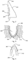
- Fig. 3 shows a schematic sectional view of a mold in the production of a wind turbine rotor blade according to an aspect of the present invention.
- a mold 300 that is used in making a rotor blade in accordance with one aspect of the present invention.
- the mold 300 has a recess 310 into which the fiber fabric (glass fiber or carbon fiber) for producing the rotor blade of the wind energy installation is inserted.
- a liquid erosion protection material 260 is first introduced (ie before the (glass) fiber scrims 270 are inserted). This can be done using a brush or roller (for example, this can be done using a flat brush). After the erosion protection material 260 has hardened sufficiently, (glass) fiber scrims 270 can be inserted into the mold by at least to be able to form part of the rotor blade. Finally, a vacuum infusion is carried out so that from the erosion control material 260, the inserted (glass) fiber layers 270 and z. B. epoxy resin 280 a component is made of composite material or a composite material component is produced, which can be used to manufacture the rotor blade of the wind turbine.
- the liquid erosion control material can, for. B. 6D1100 from the manufacturer Bergolin or ALEXIT LE Protect 443-EE from the manufacturer Mankiewicz.
- the time it takes for the anti-erosion material to cure can be, for. B. be between 10 minutes and 60 minutes.
- a vacuum infusion bag or film 280 can be placed over it and a vacuum infusion can be carried out, in which in particular epoxy resin is introduced by means of vacuum infusion and is then cured, so that a composite component is obtained.
- Fig. 4 shows a schematic partial sectional view of a wind turbine rotor blade.
- the rotor blade 200 has a rotor blade leading edge 210.
- Cured erosion protection material 260 is provided at least partially in the area of the rotor blade leading edge 210.
- the leading edge of the rotor blade has fiber fabrics which have been produced by means of a vacuum infusion process and, for example, epoxy resin.
- a method for producing a wind turbine rotor blade is provided.
- a liquid erosion protection material is introduced into a mold for producing a rotor blade, which is used in particular for producing the rotor blade leading edge, so that in particular the rotor blade leading edge is formed with it.
- fiberglass or carbon scrims are placed in the mold.
- a vacuum infusion bag is then placed over the mold and a vacuum infusion, in particular of epoxy resin, is carried out in order to obtain a composite component as part of the rotor blade.
Landscapes
- Engineering & Computer Science (AREA)
- Mechanical Engineering (AREA)
- Chemical & Material Sciences (AREA)
- Composite Materials (AREA)
- Life Sciences & Earth Sciences (AREA)
- Sustainable Development (AREA)
- Sustainable Energy (AREA)
- Combustion & Propulsion (AREA)
- General Engineering & Computer Science (AREA)
- Manufacturing & Machinery (AREA)
- Wind Motors (AREA)
Abstract
Es wird ein Verfahren zum Herstellen eines Windenergieanlagen-Rotorblattes (200) vorgesehen. Eine Form (300) zur Herstellung zumindest eines Teils des Windenergieanlagen-Rotorblattes (200) wird bereitgestellt. Die Form (300) weist eine Ausnehmung (310) auf, welche zur Herstellung zumindest eines Teils des Windenergieanlagen-Rotorblattes (200) verwendet wird. Flüssiges Erosionsschutzmaterial (260) wird in die Ausnehmung (310) eingetragen. Fasergelege werden in die Ausnehmung (310) der Form (300) platziert, nachdem das flüssige Erosionsschutzmaterial (260) zumindest teilweise ausgehärtet ist. Ein Vakuuminfusionsbeutel oder eine Vakuuminfusionsfolie (280) wird platziert und eine Vakuuminfusion wird mit einem Harz (280) durchgeführt, um ein Verbundbauteil zumindest als Teil des Windenergieanlagen-Rotorblattes (200) zu erhalten.
Description
- Die vorliegende Erfindung betrifft ein Verfahren zum Herstellen eines Windenergieanlagen-Rotorblattes sowie ein Windenergieanlagen-Rotorblatt.
- Die Rotorblätter der Windenergieanlage sind ständig wechselnden Witterungsbedingungen ausgesetzt, die zu Beschädigungen an den Rotorblättern der Windenergieanlage führen können. Zur Reduzierung der Beschädigungen an den Rotorblättern der Windenergieanlage ist es bekannt, eine Erosionsschutzfolie auf die Oberfläche des Rotorblattes aufzubringen. Alternativ dazu kann ein Erosionsschutz nachträglich auf das Rotorblatt durch Aufbringen eines Erosionsschutzmaterials mittels Rollen oder Pinsel erfolgen. Die Verwendung einer Erosionsschutzfolie, welche nachträglich auf die Oberfläche des Rotorblattes geklebt werden muss, oder die Verwendung eines flüssigen Erosionsschutzmittels, welches mittels Rollen und Pinsel auf die Oberfläche des Rotorblattes aufgebracht werden muss, ist jedoch nachteilig, weil damit die aerodynamische Oberfläche des Rotorblattes beeinträchtigt werden kann. Ferner ist ein Aufbringen des Erosionsschutzes auf die Oberfläche des Rotorblattes ebenfalls zeitintensiv.
- In der prioritätsbegründenden deutschen Patentanmeldung hat das Deutsche Patent- und Markenamt die folgenden Dokumente recherchiert:
US 2019/0153995 A1 ,US 2017/0058865 A1 ,US 2017/0145988 A1 ,DE 10 2015 115 190 A1 ,DE 10 2013 108 358 A1 ,DE 10 2008 055 479 A1 ,DE 10 2016 213 206 A1 ,EP 2 708 740 A1 ,WO 2012/113 966 A1 undWO 2016/030 170 A1 . - Es ist daher eine Aufgabe der vorliegenden Erfindung, ein Verfahren zum Herstellen eines Windenergieanlagen-Rotorblattes vorzusehen, welches eine verbesserte Erosionsbeständigkeit des Rotorblattes ermöglicht.
- Diese Aufgabe wird durch ein Verfahren nach Anspruch 1 sowie durch ein Windenergieanlagen-Rotorblatt nach Anspruch 3 gelöst.
- Somit wird ein Verfahren zum Herstellen eines Windenergieanlagen-Rotorblattes vorgesehen. Eine Form zur Herstellung zumindest eines Teils des Windenergieanlagen-Rotorblattes wird bereitgestellt. Die Form weist eine Ausnehmung auf, welche zur Herstellung zumindest eines Teils des Windenergieanlagen-Rotorblattes verwendet wird. Flüssiges Erosionsschutzmaterial wird in die Ausnehmung eingetragen. Fasergelege werden in die Ausnehmung der Form platziert, nachdem das flüssige Erosionsschutzmaterial zumindest teilweise ausgehärtet ist. Ein Vakuuminfusionsbeutel oder eine Vakuuminfusionsfolie wird platziert und eine Vakuuminfusion wird mit einem Harz durchgeführt, um ein Verbundbauteil zumindest als Teil des Windenergieanlagen-Rotorblattes zu erhalten.
- Durch die Verwendung eines flüssigen Erosionsschutzmaterials kann das Erosionsschutzmaterial besser an die Konturen der Ausnehmung der Form angepasst werden. Das flüssige Material dringt besser auch in komplexe Konturen der Ausnehmung der Form ein und gewährleistet einen besseren Erosionsschutz auch in komplexen Konturen. Ferner können sowohl Lufteinschlüsse als auch Harzeinschlüsse zwischen der Form und dem Erosionsschutzmaterial vermieden werden. Das flüssige Erosionsschutzmaterial ist ebenfalls prozesssicherer, da das flüssige Erosionsschutzmaterial in der Form nicht verrutschen kann. Das flüssige Erosionsschutzmaterial erlaubt ferner eine schnellere und damit kostengünstigere Verarbeitung.
- Gemäß einem Aspekt der vorliegenden Erfindung wird ein Erosionsschutzmaterial (beispielsweise in flüssiger Form) in eine Form zur Herstellung eines Windenergieanlagen-Rotorblattes eingebracht. Nachdem das Erosionsschutzmaterial zumindest teilweise getrocknet bzw. gehärtet ist, können wie in üblicher Form Glasfasergelege in die Form eingelegt werden, um das Rotorblatt herzustellen. Anschließend wird ein Vakuuminfusionsverfahren durchgeführt, so dass sich das Erosionsschutzmaterial sowie die Glasfasergelege und das Epoxidharz verbindet und ein Rotorblatt aus Verbundmaterial mit bereits integriertem Erosionsschutz im Bereich der Vorderkante erreicht wird.
- Gemäß einem Aspekt der vorliegenden Erfindung befindet sich die Vorderkante im tiefsten Bereich der Form, so dass das Erosionsschutzmaterial im Bereich der Vorderkante vorgesehen ist.
- Gemäß einem Aspekt der vorliegenden Erfindung können Vorderkantenkappen mit integriertem Erosionsschutzmaterial vorgesehen werden.
- Mit dem erfindungsgemäßen Verfahren kann somit ein Windenergieanlagen-Rotorblatt hergestellt werden, wobei ein optimaler Erosionsschutz insbesondere im Bereich der Rotorblattvorderkante erreicht wird. Ferner kann eine verbesserte Konturtreue des Bauteils auch nach längerem Betrieb erreicht werden.
- Die Erfindung betrifft ebenfalls ein Windenergieanlagen-Rotorblatt mit einer Rotorblattvorderkante, einer Rotorblatthinterkante, einem Rotorblattwurzelbereich und einem Rotorblattspitzenbereich. Mittels des Rotorblattwurzelbereichs kann das Rotorblatt an einer Nabe einer Windenergieanlage befestigt werden. Im Bereich der Rotorblattvorderkante ist ein Verbundbauteil vorgesehen, welches mittels Vakuuminfusionsverfahren hergestellt wird und ein ausgehärtetes Erosionsschutzmaterial sowie Fasergelege aufweist. Das Erosionsschutzmaterial stellt zumindest teilweise die äußere Oberfläche des Verbundbauteils und damit der Rotorblattvorderkante dar.
- Weitere Ausgestaltungen der Erfindung sind Gegenstand der Unteransprüche.
- Vorteile und Ausführungsbeispiele der Erfindung werden nachstehend unter Bezugnahme auf die Zeichnung näher erläutert.
- Fig. 1
- zeigt eine schematische Darstellung einer Windenergieanlage gemäß einem Aspekt der vorliegenden Erfindung,
- Fig. 2
- zeigt eine schematische Darstellung eines Windenergieanlagen-Rotorblattes gemäß einem Aspekt der vorliegenden Erfindung,
- Fig. 3
- zeigt eine schematische Schnittansicht einer Form bei der Herstellung eines Windenergieanlagen-Rotorblattes gemäß einem Aspekt der vorliegenden Erfindung, und
- Fig. 4
- zeigt eine schematische Teilschnittansicht eines WindenergieanlagenRotorblattes gemäß einem Aspekt der vorliegenden Erfindung.
-
Fig. 1 zeigt eine schematische Darstellung einer Windenergieanlage gemäß einem Aspekt der vorliegenden Erfindung. Die Windenergieanlage 100 weist einen Turm 102 und eine Gondel 104 auf dem Turm 102 auf. An der Gondel 104 ist ein aerodynamischer Rotor 106 mit drei Rotorblättern 200 und einem Spinner 110 vorgesehen. Der aerodynamische Rotor 106 wird im Betrieb der Windenergieanlage durch den Wind in eine Drehbewegung versetzt und dreht somit auch einen Rotor oder Läufer eines Generators, welcher direkt oder indirekt mit dem aerodynamischen Rotor 106 gekoppelt ist. Der elektrische Generator ist in der Gondel 104 angeordnet und erzeugt elektrische Energie. Die Pitchwinkel der Rotorblätter 108 können durch Pitchmotoren an den Rotorblattwurzeln 108b der jeweiligen Rotorblätter 108 verändert werden. -
Fig. 2 zeigt eine schematische Darstellung eines Windenergieanlagen-Rotorblattes gemäß einem Aspekt der vorliegenden Erfindung. Das Rotorblatt 200 weist eine Rotorblattvorderkante 210, eine Rotorblatthinterkante 220, einen Rotorblattwurzelbereich 230 und eine Rotorblattspitze 240 auf. Mittels des Rotorblattwurzelbereiches 230 kann das Rotorblatt an einer Nabe der Windenergieanlage befestigt werden. Das Rotorblatt weist ferner eine Rotorblattvorderkappe 250 auf, welche ein Erosionsschutzmaterial 260 aufweisen kann. Das Erosionsschutzmaterial 260 stellt zumindest teilweise die Oberfläche des Rotorblattes insbesondere im Bereich der Rotorblattvorderkante 210 dar. Die Rotorblattvorderkante 210 bzw. die Rotorblattvorderkappe 250 kann zumindest teilweise als ein Faserverbundbauteil ausgestaltet sein, wobei das Erosionsschutzmaterial zumindest teilweise die Oberfläche des Faserverbundbauteils darstellt. Das Faserverbundbauteil kann insbesondere mittels eines Vakuuminfusionsverfahrens hergestellt werden, wobei das Erosionsschutzmaterial Teil des Verbundbauteils ist. -
Fig. 3 zeigt eine schematische Schnittansicht einer Form bei der Herstellung eines Windenergieanlagen-Rotorblattes gemäß einem Aspekt der vorliegenden Erfindung. InFig. 3 ist eine Form 300 gezeigt, welche zur Verwendung einer Herstellung eines Rotorblattes gemäß einem Aspekt der vorliegenden Erfindung verwendet wird. Dazu weist die Form 300 eine Ausnehmung 310 auf, in welche die Fasergelege (Glasfaser oder Kohlestofffaser) zur Herstellung des Rotorblattes der Windenergieanlage eingelegt werden. - Gemäß einem Aspekt der vorliegenden Erfindung wird zunächst (d. h. bevor die (Glas)Fasergelege 270 eingelegt werden) ein flüssiges Erosionsschutzmaterial 260 eingetragen. Dies kann mittels eines Pinsels oder einer Rolle erfolgen (beispielsweise kann dies mittels eines Flachpinsels erfolgen). Nachdem das Erosionsschutzmaterial 260 ausreichend gehärtet ist, können (Glas)Fasergelege 270 in die Form eingelegt werden, um mindestens einen Teil des Rotorblattes ausbilden zu können. Schließlich wird eine Vakuuminfusion durchgeführt, so dass aus dem Erosionsschutzmaterial 260, den eingelegten (Glas)Fasergelegen 270 sowie z. B. Epoxidharz 280 ein Bauteil aus Verbundmaterial hergestellt wird bzw. ein Verbundmaterialbauteil hergestellt wird, welches zur Herstellung des Rotorblattes der Windenergieanlage verwendet werden kann.
- Das flüssige Erosionsschutzmaterial kann z. B. 6D1100 vom Hersteller Bergolin oder ALEXIT LE Protect 443-EE vom Hersteller Mankiewicz sein. Die Zeit, die zum Aushärten des Erosionsschutzmaterials benötigt wird, kann z. B. zwischen 10 min. und 60 min. betragen.
- Nachdem die Glasfasergelege entsprechend in die Form eingebracht worden sind, kann ein Vakuuminfusionsbeutel oder-folie 280 darüber platziert werden und eine Vakuuminfusion kann durchgeführt werden, bei der insbesondere Epoxidharz mittels Vakuuminfusion eingeführt wird und anschließend ausgehärtet wird, so dass ein Verbundbauteil erhalten wird.
-
Fig. 4 zeigt eine schematische Teilschnittansicht eines Windenergieanlagen-Rotorblattes. Das Rotorblatt 200 weist eine Rotorblattvorderkante 210 auf. Zumindest teilweise im Bereich der Rotorblattvorderkante 210 ist ausgehärtetes Erosionsschutzmaterial 260 vorgesehen. Ferner weist die Rotorblattvorderkante Fasergelege auf, welche mittels eines Vakuuminfusionsverfahrens und beispielsweise Epoxidharz hergestellt worden sind. - Gemäß einem Aspekt der vorliegenden Erfindung wird ein Verfahren zum Herstellen eines Windenergieanlagen-Rotorblattes vorgesehen. In eine Form zur Herstellung eines Rotorblattes, welche insbesondere zur Herstellung der Rotorblattvorderkante dient, wird ein flüssiges Erosionsschutzmaterial eingetragen, so dass insbesondere die Rotorblattvorderkante damit ausgebildet wird. Nach ausreichendem Aushärten des flüssigen Erosionsschutzmaterials werden Glasfasergelege oder Kohlenstoffgelege in die Form platziert. Anschließend wird ein Vakuuminfusionsbeutel über die Form platziert und eine Vakuuminfusion insbesondere von Epoxidharz wird durchgeführt, um ein Verbundbauteil als Teil des Rotorblattes zu erhalten.
Claims (3)
- Verfahren zum Herstellen eines Windenergieanlagen-Rotorblattes (200), mit den Schritten:Bereitstellen einer Form (300) zur Herstellung zumindest eines Teils des Windenergieanlagen-Rotorblattes (200), wobei die Form (300) eine Ausnehmung (310) aufweist, welche zur Herstellung zumindest eines Teils des Windenergieanlagen-Rotorblattes (200) verwendet wird,Eintragen von flüssigem Erosionsschutzmaterial (260) in die Ausnehmung (310),Platzieren von Fasergelegen in die Ausnehmung (310) der Form (300), nachdem das flüssige Erosionsschutzmaterial (260) zumindest teilweise ausgehärtet ist,Platzieren eines Vakuuminfusionsbeutels oder einer Vakuuminfusionsfolie (280) undDurchführen einer Vakuuminfusion mit einem Harz (280), um ein Verbundbauteil zumindest als Teil des Windenergieanlagen-Rotorblattes (200) zu erhalten.
- Verfahren zum Herstellen eines Windenergieanlagen-Rotorblattes nach Anspruch 1, wobei
das Erosionsschutzmaterial (260) im Bereich einer Rotorblattvorderkante (210) vorgesehen ist. - Windenergieanlagen-Rotorblatt, mit
einer Rotorblattvorderkante (210), einer Rotorblatthinterkante (220), einem Rotorblattwurzelbereich (230) und einem Rotorblattspitzenbereich (240),
ausgehärtetem Erosionsschutzmaterial (260), insbesondere im Bereich der Rotorblattvorderkante (210),
Fasergelegen (270),
wobei das ausgehärtete Erosionsschutzmaterial (260) und die Fasergelege (270) ein mittels Vakuuminfusionsverfahren hergestelltes Verbundbauteil darstellen.
Applications Claiming Priority (1)
| Application Number | Priority Date | Filing Date | Title |
|---|---|---|---|
| DE102020100275 | 2020-01-09 |
Publications (1)
| Publication Number | Publication Date |
|---|---|
| EP3848574A1 true EP3848574A1 (de) | 2021-07-14 |
Family
ID=74105836
Family Applications (1)
| Application Number | Title | Priority Date | Filing Date |
|---|---|---|---|
| EP21150395.8A Withdrawn EP3848574A1 (de) | 2020-01-09 | 2021-01-06 | Verfahren zum herstellen eines windenergieanlagen-rotorblattes |
Country Status (3)
| Country | Link |
|---|---|
| US (1) | US20210231099A1 (de) |
| EP (1) | EP3848574A1 (de) |
| CN (1) | CN113085219A (de) |
Citations (12)
| Publication number | Priority date | Publication date | Assignee | Title |
|---|---|---|---|---|
| DE102008055479A1 (de) | 2007-12-07 | 2009-06-10 | General Electric Company | Verfahren und Vorrichtung zur Herstellung von Windkraftanlagenkomponenten |
| US20110316182A1 (en) * | 2009-03-06 | 2011-12-29 | Lm Glasfiber A/S | Method and manufacturing line for manufacturing wind turbine blades |
| WO2012113966A1 (es) | 2011-02-25 | 2012-08-30 | Francisco Javier Garcia Castro | Procedimiento para la fabricación de palas eólicas, palas para hélices, alas o estructuras similares y estructura en forma de pala obtenida mediante dicho procedimiento |
| EP2708740A1 (de) | 2012-09-17 | 2014-03-19 | Nordex Energy GmbH | Windenergieanlagenrotorblatt mit einer elektrischen Heizeinrichtung und einem Blitzableiter |
| DE102013108358A1 (de) | 2013-08-02 | 2015-02-05 | Senvion Se | Vorderkanten-Finish mittels Vakuuminfusion |
| WO2016030170A1 (en) | 2014-08-27 | 2016-03-03 | Basf Se | Rotor blade element with anti-icing surface for wind turbine rotor blades |
| US20170058865A1 (en) | 2015-08-26 | 2017-03-02 | General Electric Company | Modular wind turbine rotor blade constructed of multiple resin systems |
| DE102015115190A1 (de) | 2015-09-09 | 2017-03-09 | Fichtner & Schicht GmbH | Windenergieanlage |
| US20170145988A1 (en) | 2015-11-24 | 2017-05-25 | Gamesa Innovation & Technology, S. L. | Wind turbine blade comprising a lightning protection system equipped with radar absorbing material |
| DE102016213206A1 (de) | 2016-07-19 | 2018-01-25 | Wobben Properties Gmbh | Mehrschichtiges Verbundbauteil |
| US20190153995A1 (en) | 2017-11-21 | 2019-05-23 | General Electric Company | Methods for manufacturing an outer skin of a rotor blade |
| CN110588018A (zh) * | 2019-09-24 | 2019-12-20 | 上海麦加涂料有限公司 | 一种风力发电机叶片用模内胶衣的涂装成型方法及风力发电机叶片成型方法 |
Family Cites Families (5)
| Publication number | Priority date | Publication date | Assignee | Title |
|---|---|---|---|---|
| DE102011078951C5 (de) * | 2011-07-11 | 2017-09-07 | Senvion Gmbh | Verfahren zum Herstellen eines Rotorblatts für eine Windenergieanlage |
| GB201313779D0 (en) * | 2013-08-01 | 2013-09-18 | Blade Dynamics Ltd | Erosion resistant aerodynamic fairing |
| EP2927482A1 (de) * | 2014-04-01 | 2015-10-07 | LM WP Patent Holding A/S | Windturbinenschaufel mit Erosionsschild |
| CN107718593B (zh) * | 2017-10-12 | 2019-12-24 | 江苏金风科技有限公司 | 风力发电机组叶片粘接角的灌注方法及风力发电机组叶片 |
| CN108843486B (zh) * | 2018-07-30 | 2023-10-13 | 中科国风检测(天津)有限公司 | 一种风电叶片前缘防护系统及施工工艺 |
-
2021
- 2021-01-06 EP EP21150395.8A patent/EP3848574A1/de not_active Withdrawn
- 2021-01-07 US US17/143,772 patent/US20210231099A1/en not_active Abandoned
- 2021-01-11 CN CN202110032913.1A patent/CN113085219A/zh active Pending
Patent Citations (12)
| Publication number | Priority date | Publication date | Assignee | Title |
|---|---|---|---|---|
| DE102008055479A1 (de) | 2007-12-07 | 2009-06-10 | General Electric Company | Verfahren und Vorrichtung zur Herstellung von Windkraftanlagenkomponenten |
| US20110316182A1 (en) * | 2009-03-06 | 2011-12-29 | Lm Glasfiber A/S | Method and manufacturing line for manufacturing wind turbine blades |
| WO2012113966A1 (es) | 2011-02-25 | 2012-08-30 | Francisco Javier Garcia Castro | Procedimiento para la fabricación de palas eólicas, palas para hélices, alas o estructuras similares y estructura en forma de pala obtenida mediante dicho procedimiento |
| EP2708740A1 (de) | 2012-09-17 | 2014-03-19 | Nordex Energy GmbH | Windenergieanlagenrotorblatt mit einer elektrischen Heizeinrichtung und einem Blitzableiter |
| DE102013108358A1 (de) | 2013-08-02 | 2015-02-05 | Senvion Se | Vorderkanten-Finish mittels Vakuuminfusion |
| WO2016030170A1 (en) | 2014-08-27 | 2016-03-03 | Basf Se | Rotor blade element with anti-icing surface for wind turbine rotor blades |
| US20170058865A1 (en) | 2015-08-26 | 2017-03-02 | General Electric Company | Modular wind turbine rotor blade constructed of multiple resin systems |
| DE102015115190A1 (de) | 2015-09-09 | 2017-03-09 | Fichtner & Schicht GmbH | Windenergieanlage |
| US20170145988A1 (en) | 2015-11-24 | 2017-05-25 | Gamesa Innovation & Technology, S. L. | Wind turbine blade comprising a lightning protection system equipped with radar absorbing material |
| DE102016213206A1 (de) | 2016-07-19 | 2018-01-25 | Wobben Properties Gmbh | Mehrschichtiges Verbundbauteil |
| US20190153995A1 (en) | 2017-11-21 | 2019-05-23 | General Electric Company | Methods for manufacturing an outer skin of a rotor blade |
| CN110588018A (zh) * | 2019-09-24 | 2019-12-20 | 上海麦加涂料有限公司 | 一种风力发电机叶片用模内胶衣的涂装成型方法及风力发电机叶片成型方法 |
Also Published As
| Publication number | Publication date |
|---|---|
| US20210231099A1 (en) | 2021-07-29 |
| CN113085219A (zh) | 2021-07-09 |
Similar Documents
| Publication | Publication Date | Title |
|---|---|---|
| EP2731789B1 (de) | Einrichtung und verfahren zur fertigung eines bauteils | |
| DE102008044530A1 (de) | Gießformen für Windkraftanlagen-Rotorflügel | |
| DE102009003421A1 (de) | Rotorflügel einer Windkraftanlage und Verfahren zur Herstellung desselben | |
| DE102014206345A1 (de) | Verfahren zum Anbringen einer Zackenhinterkante an einer Blatthinterkante eines Rotorblattes | |
| EP2561977B1 (de) | Verfahren zur Herstellung eines Windenergieanlagenrotorblattteils mit einem kohlenstofffaserverstärkten Hauptgurt | |
| EP2382375A2 (de) | Turbinenschaufel, insbesondere laufschaufel für eine dampfturbine, sowie herstellungsverfahren hierfür | |
| WO2017085088A1 (de) | Windenergieanlagen-rotorblatt und windenergieanlage | |
| EP3634730B1 (de) | Verfahren zum herstellen eines windenergieanlagen-rotorblattes | |
| DE102016125062A1 (de) | Windenergieanlagen-Turm und Windenergieanlagen-Turmübergangssegment | |
| EP4070890B1 (de) | Verfahren zum auftragen eines materials auf eine oberfläche eines windenergieanlagen-rotorblattes und material-applikator | |
| DE102018100941A1 (de) | Verfahren zum Herstellen von Komponenten einer Windenergieanlage, insbesondere eines Windenergieanlagen-Rotorblattes | |
| EP2985138B1 (de) | Rotorblatt für eine windkraftanlage und verfahren zur herstellung des rotorblattes | |
| WO2014177363A2 (de) | Synchrongenerator-stator und synchrongenerator | |
| EP4219934B1 (de) | Verfahren zur reduzierung einer geräuschemission eines windenergieanlagen-rotorblattes und windenergieanlagen-rotorblatt | |
| EP3735533B1 (de) | Verfahren zum steuern einer windenergieanlage sowie windenergieanlage | |
| EP3615792B1 (de) | Windenergieanlagen-rotorblatt und verfahren zum herstellen eines windenergieanlagen-rotorblattes | |
| DE102008019890A1 (de) | Dichtungsanordnung | |
| EP3317069A1 (de) | Verfahren zum herstellen eines windenergieanlagen-rotorblattes und windenergieanlagen-rotorblatt | |
| DE102009010613A1 (de) | Verfahren zum Anbringen bzw. Herstellen eines geschlossenen Deckbandes für eine Laufbeschaufelung einer Turbinenstufe sowie Laufbeschaufelung einer Turbinenstufe für eine Turbine | |
| EP3412438A1 (de) | System zum herstellen einer pultrusionsplanke für ein rotorblatt einer windenergieanlage, verfahren und schleifvorrichtung | |
| EP4534276A1 (de) | Windenergieanlagen-rotorblatt-hinterkantenkamm und verfahren zum herstellen eines windenergieanlagen-rotorblattes | |
| WO2018015098A1 (de) | Windenergieanlagen-rotorblatt und windenergieanlagen-rotorblattspitze | |
| DE102015217331A1 (de) | Verfahren zum Nachrüsten einer Zackeneinheit an einer Hinterkante eines Windenergieanlagen-Rotorblattes und Zacken-Nachrüsteinheit für ein Windenergieanlagen-Rotorblatt | |
| EP3924620B1 (de) | Verfahren zum reparieren eines windenergieanlagen-rotorblattes | |
| US20210231099A1 (en) | Method for manufacturing a wind power plant rotor blade |
Legal Events
| Date | Code | Title | Description |
|---|---|---|---|
| PUAI | Public reference made under article 153(3) epc to a published international application that has entered the european phase |
Free format text: ORIGINAL CODE: 0009012 |
|
| STAA | Information on the status of an ep patent application or granted ep patent |
Free format text: STATUS: THE APPLICATION HAS BEEN PUBLISHED |
|
| AK | Designated contracting states |
Kind code of ref document: A1 Designated state(s): AL AT BE BG CH CY CZ DE DK EE ES FI FR GB GR HR HU IE IS IT LI LT LU LV MC MK MT NL NO PL PT RO RS SE SI SK SM TR |
|
| STAA | Information on the status of an ep patent application or granted ep patent |
Free format text: STATUS: THE APPLICATION IS DEEMED TO BE WITHDRAWN |
|
| 18D | Application deemed to be withdrawn |
Effective date: 20220115 |