EP3848262A1 - Connector for setting layout of brake hose - Google Patents
Connector for setting layout of brake hose Download PDFInfo
- Publication number
- EP3848262A1 EP3848262A1 EP20217762.2A EP20217762A EP3848262A1 EP 3848262 A1 EP3848262 A1 EP 3848262A1 EP 20217762 A EP20217762 A EP 20217762A EP 3848262 A1 EP3848262 A1 EP 3848262A1
- Authority
- EP
- European Patent Office
- Prior art keywords
- coupling member
- tube body
- length
- linking portion
- connector
- Prior art date
- Legal status (The legal status is an assumption and is not a legal conclusion. Google has not performed a legal analysis and makes no representation as to the accuracy of the status listed.)
- Granted
Links
Images


Classifications
-
- F—MECHANICAL ENGINEERING; LIGHTING; HEATING; WEAPONS; BLASTING
- F16—ENGINEERING ELEMENTS AND UNITS; GENERAL MEASURES FOR PRODUCING AND MAINTAINING EFFECTIVE FUNCTIONING OF MACHINES OR INSTALLATIONS; THERMAL INSULATION IN GENERAL
- F16L—PIPES; JOINTS OR FITTINGS FOR PIPES; SUPPORTS FOR PIPES, CABLES OR PROTECTIVE TUBING; MEANS FOR THERMAL INSULATION IN GENERAL
- F16L55/00—Devices or appurtenances for use in, or in connection with, pipes or pipe systems
-
- B—PERFORMING OPERATIONS; TRANSPORTING
- B60—VEHICLES IN GENERAL
- B60T—VEHICLE BRAKE CONTROL SYSTEMS OR PARTS THEREOF; BRAKE CONTROL SYSTEMS OR PARTS THEREOF, IN GENERAL; ARRANGEMENT OF BRAKING ELEMENTS ON VEHICLES IN GENERAL; PORTABLE DEVICES FOR PREVENTING UNWANTED MOVEMENT OF VEHICLES; VEHICLE MODIFICATIONS TO FACILITATE COOLING OF BRAKES
- B60T17/00—Component parts, details, or accessories of power brake systems not covered by groups B60T8/00, B60T13/00 or B60T15/00, or presenting other characteristic features
- B60T17/04—Arrangements of piping, valves in the piping, e.g. cut-off valves, couplings or air hoses
- B60T17/046—Devices for pipe guiding and fixing
-
- B—PERFORMING OPERATIONS; TRANSPORTING
- B60—VEHICLES IN GENERAL
- B60T—VEHICLE BRAKE CONTROL SYSTEMS OR PARTS THEREOF; BRAKE CONTROL SYSTEMS OR PARTS THEREOF, IN GENERAL; ARRANGEMENT OF BRAKING ELEMENTS ON VEHICLES IN GENERAL; PORTABLE DEVICES FOR PREVENTING UNWANTED MOVEMENT OF VEHICLES; VEHICLE MODIFICATIONS TO FACILITATE COOLING OF BRAKES
- B60T17/00—Component parts, details, or accessories of power brake systems not covered by groups B60T8/00, B60T13/00 or B60T15/00, or presenting other characteristic features
- B60T17/04—Arrangements of piping, valves in the piping, e.g. cut-off valves, couplings or air hoses
- B60T17/043—Brake line couplings, air hoses and stopcocks
-
- F—MECHANICAL ENGINEERING; LIGHTING; HEATING; WEAPONS; BLASTING
- F16—ENGINEERING ELEMENTS AND UNITS; GENERAL MEASURES FOR PRODUCING AND MAINTAINING EFFECTIVE FUNCTIONING OF MACHINES OR INSTALLATIONS; THERMAL INSULATION IN GENERAL
- F16C—SHAFTS; FLEXIBLE SHAFTS; ELEMENTS OR CRANKSHAFT MECHANISMS; ROTARY BODIES OTHER THAN GEARING ELEMENTS; BEARINGS
- F16C11/00—Pivots; Pivotal connections
- F16C11/04—Pivotal connections
- F16C11/06—Ball-joints; Other joints having more than one degree of angular freedom, i.e. universal joints
-
- F—MECHANICAL ENGINEERING; LIGHTING; HEATING; WEAPONS; BLASTING
- F16—ENGINEERING ELEMENTS AND UNITS; GENERAL MEASURES FOR PRODUCING AND MAINTAINING EFFECTIVE FUNCTIONING OF MACHINES OR INSTALLATIONS; THERMAL INSULATION IN GENERAL
- F16L—PIPES; JOINTS OR FITTINGS FOR PIPES; SUPPORTS FOR PIPES, CABLES OR PROTECTIVE TUBING; MEANS FOR THERMAL INSULATION IN GENERAL
- F16L27/00—Adjustable joints; Joints allowing movement
- F16L27/12—Adjustable joints; Joints allowing movement allowing substantial longitudinal adjustment or movement
- F16L27/125—Adjustable joints; Joints allowing movement allowing substantial longitudinal adjustment or movement having longitudinal and rotary movement
-
- G—PHYSICS
- G01—MEASURING; TESTING
- G01B—MEASURING LENGTH, THICKNESS OR SIMILAR LINEAR DIMENSIONS; MEASURING ANGLES; MEASURING AREAS; MEASURING IRREGULARITIES OF SURFACES OR CONTOURS
- G01B5/00—Measuring arrangements characterised by the use of mechanical techniques
- G01B5/14—Measuring arrangements characterised by the use of mechanical techniques for measuring distance or clearance between spaced objects or spaced apertures
Definitions
- the disclosure relates to a connector for setting a layout of a brake hose. More particularly, the disclosure relates to a layout setting connector capable of adjusting a layout of a brake hose in a test process of setting the layout of the brake hose.
- the hydraulic pressure is generated from a master cylinder responsive to the operation of a brake pedal, and when the hydraulic pressure is applied to a cylinder in a caliper housing through a brake pipe and a brake hose, a brake pad comes into contact with a disk to generate a braking force.
- the brake hose supplying a brake oil should have flexibility so that it is varied in shape according to the movement of the wheel. For this reason, a rubber hose is mainly used as the brake hose.
- the brake hose has to be installed stably without causing interference with other parts around it. Because the vehicle is directly connected to a driver's life, strict management of respective vehicle parts is required, and it is more important especially in the brake system.
- FIG. 1 is a view showing connectors coupled to both ends of a brake hose generally applied to a vehicle.
- the brake hose H is coupled at both ends to a first connector 30 and a second connector 40.
- the first connector 30 is connected to a frame (not shown) of a master cylinder through a bracket 20, and the second connector 40 is connected to a caliper housing (not shown) of the vehicle through a benzo bolt.
- the brake hose H can be disposed between the caliper housing and the frame.
- each of the connectors 30 and 40 should be configured in a specific shape to avoid interference between the brake hose H and surrounding parts.
- each of the connectors 30 and 40 is formed to be bent in a predetermined direction while having a predetermined length avoiding interference between the brake hose H and surrounding parts.
- a layout setting test is conducted so that the brake hose H can avoid interference with surrounding parts.
- a conventional test for setting the layout of the brake hose H is performed by actually installing the brake hose H in the vehicle through the connectors 30 and 40 when the design of the connectors 30 and 40 coupled to both ends of the brake hose H is completed. That is, the test is performed to check whether any interference occurs while driving between the brake hose H and the surrounding parts.
- the connectors 30 and 40 are removed from the vehicle and their lengths and bend directions are redesigned. Then, the redesigned connectors are mounted again in the vehicle and the test is repeated. Therefore, it takes a lot of time to set the layout of the brake hose H, and also the manufacturing cost is increased unnecessarily.
- the disclosure provides a connector for setting a layout of a brake hose.
- the setting connector used to set the layout of the brake hose is implemented so that its length and bend direction can be adjusted. Therefore, using the setting connector makes it possible to accurately set the shape of a connector to be actually disposed in a vehicle while being coupled to the brake hose.
- a connector for setting a layout of a brake hose disposed between a caliper housing and a frame of a master cylinder in a vehicle may include a first coupling member coupled to one end of the brake hose; a second coupling member disposed to be spaced apart from the first coupling member, and coupled to the caliper housing or the frame of the master cylinder; and an adjusting unit connected at one end thereof to the first coupling member, connected at other end thereof to the second coupling member, and configured to adjust a shortest length between a bottom surface of the first coupling member and an outer circumferential surface of the second coupling member and to adjust a line passing through a center of the first coupling member with respect to the second coupling member to be positioned in one of up/down/left/right directions, in a test for setting the layout of the brake hose.
- the adjusting unit may include a length adjuster including a first length adjusting bar connected at one end thereof to the second coupling member, and a first tube body slidably coupled to other end of the first length adjusting bar; and a position adjuster including a first linking portion formed at other end of the first tube body, a second tube body connected at one end thereof to the first coupling member and having a bent portion at the other end thereof, and a second linking portion formed at an end of the bent portion and combined with or separated from the first linking portion.
- FIGS. 2 to 13 a connector for setting a layout of a brake hose according to various embodiments of the disclosure will be described with reference to FIGS. 2 to 13 .
- FIG. 2 is a perspective view showing a structure of a connector for setting according to a first embodiment of the disclosure
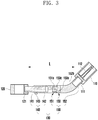
- FIG. 3 is a cross-sectional view showing the structure of the setting connector according to the first embodiment of the disclosure.
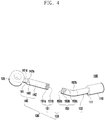
- FIG. 4 is a perspective view showing a state in which first and second linking portions are separated from each other in order to adjust a bend direction of the setting connector according to the first embodiment of the disclosure
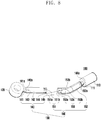
- FIG. 5 is a perspective view showing an operating state of the setting connector according to the first embodiment of the disclosure.
- a setting connector 100 is used for setting the layout of a brake hose, especially, for accurately setting the shape of a real connector that connects one end of a brake hose (H, see FIG. 1 ) to one end of a caliper housing (10, see FIG. 11 ) or to a frame (not shown) of a master cylinder.
- the setting connector 100 may include a first coupling member 110, a second coupling member 120, and an adjusting unit 130.
- the first coupling member 110 may be formed in a tubular shape and may have therein a coupling pin 112 coupled to one end of the brake hose H.
- the one end of the brake hose H may be fitted inside the first coupling member 110, and the coupling pin 112 may be fitted inside the brake hose H.
- the brake hose H and the first coupling member 110 may be coupled to each other.
- compression by the clamping process is exemplary only, and the coupling between the brake hose H and the first coupling member 110 is not limited thereto.
- the second coupling member 120 connects the brake hose H, coupled to the first coupling member 110, to the caliper housing 10.
- the second coupling member 120 may be fixed to the caliper housing 10 by a separate fastening member (B, see FIG. 11 ).
- the adjusting unit 130 may be disposed such that one end is connected to the first coupling member 110 and the other end is connected to the second coupling member 120.
- the adjusting unit 130 may adjust a length (L) between the first coupling member 110 and the second coupling member 120, for example, the shortest length (L) between the bottom surface of the first coupling member 110 and the outer circumferential surface of the second coupling member 120.
- the adjusting unit 130 may adjust a line passing through the center of the first coupling member 110 with respect to the second coupling member 120 to be positioned in one of up/down/left/right directions.
- the adjusting unit 130 may include a length adjuster 140 and a position adjuster 150.
- the length adjuster 140 may include a first length adjusting bar 141 connected at one end thereof to the second coupling member 120, and a first tube body 142 slidably coupled to the other end of the first length adjusting bar 141.
- Coupling between the first length adjusting bar 141 and the first tube body 142 may be made by a coupling force that allows the first tube body 142 to slide with respect to the first length adjusting bar 141 by an operator's manipulating force in a state where the first tube body 142 is fixed to the caliper housing 10.
- a coupling state between the first length adjusting bar 141 and the first tube body 142 may be maintained through a first fixing member 143 to be described later.
- One end of the first length adjusting bar 141 may be fixedly connected to the second coupling member 120.
- a first coupling recess 121 may be formed in the second coupling member 120 to accommodate the one end of the first length adjusting bar 141.
- FIG. 5 An operating example of the length adjuster 140 is shown in FIG. 5 .
- the first tube body 142 may slidingly move with respect to the first length adjusting bar 141 so as to adjust the overall length of the first length adjusting bar 141 and the first tube body 142. This allows adjusting the shortest length (L) between the bottom surface of the first coupling member 110 and the outer circumferential surface of the second coupling member 120.
- the length adjuster 140 may further include a first fixing member 143 that passes through a surface of the first tube body 142 and fastens the first length adjusting bar 141 residing inside the first tube body 142.
- a first fastening hole 142a into which the first fixing member 143 is inserted may be formed in the surface of the first tube body 142.
- the overall length of the first length adjusting bar 141 and the first tube body 142 can be fixed, after adjusted, by the first fixing member 143 in the test for setting the layout of the brake hose H, so that it is possible to accurately set the length of a connector to be actually applied.
- the position adjuster 150 may include a first linking portion 151, a second tube body 152, and a second linking portion 153.
- the linking portion 151 is formed at the other end of the first tube body 142.
- the second tube body 152 is connected at one end thereof to the first coupling member 110 and has a bent portion 152b at the other end thereof.
- the second linking portion 153 is formed at the end of the bent portion 152b of the second tube body 152 and combined with or separated from the first linking portion 151.
- the first linking portion 151 is composed of a plurality of first protrusions 151a protruded from the other end of the first tube body 142 and arranged at regular interval, and a plurality of first grooves 151b each formed between adjacent first protrusions 151a.
- the second linking portion 153 is composed of a second linking portion body 153a protruded from the end of the bent portion 152b of the second tube body 152, a plurality of second protrusions 151b arranged at regular intervals on the outer circumferential surface of the second linking portion body 153a, and a plurality of second grooves 153c each formed between adjacent second protrusions 153b.
- the linking portion 153 is combined with the first linking portion 151 as will be described below in detail.
- One end of the second tube body 152 may be fixedly connected to the first coupling member 110.
- a second coupling recess 111 may be formed in the first coupling member 110 to accommodate the one end of the second tube body 152.
- an operating example of the position adjuster 150 is as follows.
- the second coupling member 120 is coupled to the caliper housing 10
- the second linking portion 153 formed at the second pipe body 152 is separated from the first linking portion 151 formed at the first pipe body 142.
- the second linking portion 153 is rotated with respect to the first linking portion 151 so as to adjust a bend direction of the bent portion 152b formed at the second tube body 152.
- the first and second linking portions 151 and 153 are recombined. This allows adjusting a line passing through the center of the first coupling member 110 with respect to the second coupling member 120 to be positioned in one of up/down/left/right directions.
- the first protrusions 151a of the first linking portion 151 are inserted into the second grooves 153c of the second linking portion 153, and the second protrusions 153a of the second linking portion 153 are inserted into the first grooves 151b of the first linking portion 151. That is, the first protrusions 151a are fitted in the second grooves 153c while being in contact with the outer circumferential surface of the second linking portion body 153a.
- the length adjuster 140 may further include a first scale indication 141a formed on the outer circumferential surface of the first length adjusting bar 141 in a longitudinal direction of the first length adjusting bar 141.
- the first scale indication 141a allows identifying a moving distance of the first tube body 142 with respect to the first length adjusting bar 141.
- the first scale indication 141a clearly indicates the moving distance of the first tube body 142 with respect to the first length adjusting bar 141, so that the operator can easily identify how long the shortest length between the bottom surface of the first coupling member 110 and the outer circumferential surface of the second coupling member 120 is adjusted by the length adjuster 140.
- the layout setting connector 100 for the brake hose H is capable of adjusting the overall length of the first length adjusting bar 141 and the first tube body 142 and also adjusting the bend direction of the bent portion 152b formed at the second tube body 152. Consequently, the setting connector 100 is capable of not only adjusting the shortest length between the first coupling member 110 and the second coupling member 120, but also adjusting the line passing through the center of the first coupling member 110 with respect to the second coupling member 120 to be positioned in one of up/down/left/right directions.
- FIG. 6 is a perspective view showing a structure of a connector for setting according to a second embodiment of the disclosure
- FIG. 7 is a cross-sectional view showing the structure of the setting connector according to the second embodiment of the disclosure.
- FIG. 8 is a perspective view showing a state in which first and second linking portions are separated from each other in order to adjust a bend direction of the setting connector according to the second embodiment of the disclosure.
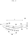
- FIG. 9 is a perspective view showing an operating state of the setting connector according to the second embodiment of the disclosure
- FIG. 10 is a perspective view showing another example of a second coupling portion of the setting connector according to the second embodiment of the disclosure.
- the connector 100 for setting the layout of the brake hose H according to the second embodiment has almost the same configuration as the above-described layout setting connector according to the first embodiment.
- the layout setting connector 100 according to the second embodiment is characterized in that the length adjuster 140 further includes a second length adjusting bar 144 which is slidably coupled to the other end of the second tube body 152 where the second linking portion 153 is formed.
- one end of the second tube body 152 is fixedly connected to the first coupling member 110, but in the second embodiment, one end of the second length adjusting bar 144 is fixedly connected to the first coupling member 110.
- the length adjuster 140 further includes the second length adjusting bar 144, the length adjustment is possible at both sides based on the position adjuster 150.
- the length adjuster 140 may further include a second fixing member 145 that passes through a surface of the second tube body 152 and fastens the second length adjusting bar 144 residing inside the second tube body 152.
- a second fastening hole 152a into which the second fixing member 145 is inserted may be formed in the surface of the second tube body 144.
- the length adjuster 140 may further include a second scale indication 144a formed on the outer circumferential surface of the second length adjusting bar 144 in a longitudinal direction of the second length adjusting bar 144.
- the second scale indication 144a allows identifying a moving distance of the second length adjusting bar 144 with respect to the second tube body 152.
- the first scale indication 141a clearly indicates the moving distance of the first tube body 142 with respect to the first length adjusting bar 141
- the second scale indication 144a clearly indicates the moving distance of the second length adjusting bar 144 with respect to the second tube body 152. Therefore, the operator can easily identify how long the shortest length between the bottom surface of the first coupling member 110 and the outer circumferential surface of the second coupling member 120 is adjusted by the length adjuster 140.
- the second coupling member 120 is implemented in a suitable shape for being fixed to the caliper housing 10
- the second coupling member 120 may be implemented in a suitable shape for being coupled to the frame of the master cylinder. That is, as shown in FIG. 10 , the second coupling member 120 may be implemented in the same shape as that of a second coupling member of the first connector 30 shown in FIG. 1 , and the second coupling member 120 having this shape may be fixed to the frame through the bracket 20 shown in FIG. 1 .
- FIG. 11 shows a state in which the setting connector coupled at one end thereof to the brake hose is combined at the other end thereof with the caliper housing
- FIG. 12 shows a state in which a second linking portion is separated from a first linking portion in order to adjust a bend direction of the setting connector
- FIG. 13 shows a state in which a second linking portion is recombined with a first linking portion after a bend direction of the setting connector is adjusted.
- one end of the brake hose H is coupled to the first coupling member 110 of the setting connector 100, and also the second coupling member 120 of the setting connector 100 is coupled to the caliper housing 10. Also, the other end of the brake hose H is connected to the master cylinder (not shown) through another connector (not shown).
- the shortest length (L) between the bottom surface of the first coupling member 110 and the outer peripheral surface of the second coupling member 120 is adjusted by slidingly moving the first tube body 142 with respect to the first length adjusting bar 141 and also slidingly moving the second length adjusting bar 144 with respect to the second tube body 152.
- the first fixing member 143 and the second fixing member 145 are tightened so as to fix the adjusted length between the first and second coupling members 110 and 120.
- the second linking portion 153 is separated from the first linking portion 151 as shown in FIG. 12 , and the bend direction of the bent portion 152b of the second tube body 152 is adjusted.
- the second linking portion 153 is recombined with the first linking portion 151 such that the second tube body 152 having the adjusted bend direction of the bent portion 152b is connected to the first tube body 151.
- the operator performs the test for setting the layout of the brake hose H. That is, while moving the suspension (not shown) up and down and steering the wheel (not shown) left and right, the operator checks whether the brake hose H causes interference with surrounding parts at the adjusted length and bend direction of the setting connector 100.
Landscapes
- Engineering & Computer Science (AREA)
- Mechanical Engineering (AREA)
- General Engineering & Computer Science (AREA)
- Transportation (AREA)
- Physics & Mathematics (AREA)
- General Physics & Mathematics (AREA)
- Valves And Accessory Devices For Braking Systems (AREA)
Abstract
Description
- The disclosure relates to a connector for setting a layout of a brake hose. More particularly, the disclosure relates to a layout setting connector capable of adjusting a layout of a brake hose in a test process of setting the layout of the brake hose.
- In a vehicle braking system using hydraulic pressure, the hydraulic pressure is generated from a master cylinder responsive to the operation of a brake pedal, and when the hydraulic pressure is applied to a cylinder in a caliper housing through a brake pipe and a brake hose, a brake pad comes into contact with a disk to generate a braking force.
- In case of a front axle of the vehicle, a wheel moves up and down depending on road surface conditions and moves left and right in response to steering of a steering wheel. Therefore, the brake hose supplying a brake oil should have flexibility so that it is varied in shape according to the movement of the wheel. For this reason, a rubber hose is mainly used as the brake hose.
- The brake hose has to be installed stably without causing interference with other parts around it. Because the vehicle is directly connected to a driver's life, strict management of respective vehicle parts is required, and it is more important especially in the brake system.
-
FIG. 1 is a view showing connectors coupled to both ends of a brake hose generally applied to a vehicle. - Referring to
FIG. 1 , the brake hose H is coupled at both ends to afirst connector 30 and asecond connector 40. Thefirst connector 30 is connected to a frame (not shown) of a master cylinder through abracket 20, and thesecond connector 40 is connected to a caliper housing (not shown) of the vehicle through a benzo bolt. In this way, the brake hose H can be disposed between the caliper housing and the frame. - Each of the
connectors connectors - In general, a layout setting test is conducted so that the brake hose H can avoid interference with surrounding parts. A conventional test for setting the layout of the brake hose H is performed by actually installing the brake hose H in the vehicle through the
connectors connectors - If the brake hose H interferes with the surrounding parts in the test for setting the layout of the brake hose H, the
connectors - The disclosure provides a connector for setting a layout of a brake hose. The setting connector used to set the layout of the brake hose is implemented so that its length and bend direction can be adjusted. Therefore, using the setting connector makes it possible to accurately set the shape of a connector to be actually disposed in a vehicle while being coupled to the brake hose.
- According to embodiments of the disclosure, a connector for setting a layout of a brake hose disposed between a caliper housing and a frame of a master cylinder in a vehicle may include a first coupling member coupled to one end of the brake hose; a second coupling member disposed to be spaced apart from the first coupling member, and coupled to the caliper housing or the frame of the master cylinder; and an adjusting unit connected at one end thereof to the first coupling member, connected at other end thereof to the second coupling member, and configured to adjust a shortest length between a bottom surface of the first coupling member and an outer circumferential surface of the second coupling member and to adjust a line passing through a center of the first coupling member with respect to the second coupling member to be positioned in one of up/down/left/right directions, in a test for setting the layout of the brake hose. In particular, the adjusting unit may include a length adjuster including a first length adjusting bar connected at one end thereof to the second coupling member, and a first tube body slidably coupled to other end of the first length adjusting bar; and a position adjuster including a first linking portion formed at other end of the first tube body, a second tube body connected at one end thereof to the first coupling member and having a bent portion at the other end thereof, and a second linking portion formed at an end of the bent portion and combined with or separated from the first linking portion.
- The above and other aspects, features and advantages of certain embodiments of the disclosure will be more apparent from the following detailed description, taken in conjunction with the accompanying drawings.
-
FIG. 1 is a view showing connectors coupled to both ends of a brake hose generally applied to a vehicle. -
FIG. 2 is a perspective view showing a structure of a connector for setting according to a first embodiment of the disclosure. -
FIG. 3 is a cross-sectional view showing the structure of the setting connector according to the first embodiment of the disclosure. -
FIG. 4 is a perspective view showing a state in which first and second linking portions are separated from each other in order to adjust a bend direction of the setting connector according to the first embodiment of the disclosure. -
FIG. 5 is a perspective view showing an operating state of the setting connector according to the first embodiment of the disclosure. -
FIG. 6 is a perspective view showing a structure of a connector for setting according to a second embodiment of the disclosure. -
FIG. 7 is a cross-sectional view showing the structure of the setting connector according to the second embodiment of the disclosure. -
FIG. 8 is a perspective view showing a state in which first and second linking portions are separated from each other in order to adjust a bend direction of the setting connector according to the second embodiment of the disclosure. -
FIG. 9 is a perspective view showing an operating state of the setting connector according to the second embodiment of the disclosure. -
FIG. 10 is a perspective view showing another example of a second coupling portion of the setting connector according to the second embodiment of the disclosure. -
FIGS. 11 to 13 are views showing operations of the setting connector according to the second embodiment of the disclosure. - Now, various embodiments of the disclosure will be described in detail with reference to the accompanying drawings. In the following description of embodiments, descriptions of techniques that are well known in the art and not directly related to the disclosure are omitted. This is to clearly convey the subject matter of the disclosure by omitting any unnecessary explanation. For the same reason, some elements in the drawings are exaggerated, omitted, or schematically illustrated. Also, the size of each element does not entirely reflect the actual size. In the drawings, the same or corresponding elements are denoted by the same reference numerals.
- Hereinafter, a connector for setting a layout of a brake hose according to various embodiments of the disclosure will be described with reference to
FIGS. 2 to 13 . -
FIG. 2 is a perspective view showing a structure of a connector for setting according to a first embodiment of the disclosure, andFIG. 3 is a cross-sectional view showing the structure of the setting connector according to the first embodiment of the disclosure.FIG. 4 is a perspective view showing a state in which first and second linking portions are separated from each other in order to adjust a bend direction of the setting connector according to the first embodiment of the disclosure, andFIG. 5 is a perspective view showing an operating state of the setting connector according to the first embodiment of the disclosure. - Referring to
FIGS. 2 to 5 , asetting connector 100 according to the first embodiment of the disclosure is used for setting the layout of a brake hose, especially, for accurately setting the shape of a real connector that connects one end of a brake hose (H, seeFIG. 1 ) to one end of a caliper housing (10, seeFIG. 11 ) or to a frame (not shown) of a master cylinder. Thesetting connector 100 may include afirst coupling member 110, asecond coupling member 120, and an adjustingunit 130. - The
first coupling member 110 may be formed in a tubular shape and may have therein acoupling pin 112 coupled to one end of the brake hose H. - The one end of the brake hose H may be fitted inside the
first coupling member 110, and thecoupling pin 112 may be fitted inside the brake hose H. - In this state, when a clamping process is performed to compress the one end of the brake hose H and the
first coupling member 110, the brake hose H and thefirst coupling member 110 may be coupled to each other. However, compression by the clamping process is exemplary only, and the coupling between the brake hose H and thefirst coupling member 110 is not limited thereto. - The
second coupling member 120 connects the brake hose H, coupled to thefirst coupling member 110, to thecaliper housing 10. Thesecond coupling member 120 may be fixed to thecaliper housing 10 by a separate fastening member (B, seeFIG. 11 ). - The adjusting
unit 130 may be disposed such that one end is connected to thefirst coupling member 110 and the other end is connected to thesecond coupling member 120. - In a test for setting the layout of the brake hose H, the adjusting
unit 130 may adjust a length (L) between thefirst coupling member 110 and thesecond coupling member 120, for example, the shortest length (L) between the bottom surface of thefirst coupling member 110 and the outer circumferential surface of thesecond coupling member 120. In addition, the adjustingunit 130 may adjust a line passing through the center of thefirst coupling member 110 with respect to thesecond coupling member 120 to be positioned in one of up/down/left/right directions. The adjustingunit 130 may include alength adjuster 140 and a position adjuster 150. - The
length adjuster 140 may include a firstlength adjusting bar 141 connected at one end thereof to thesecond coupling member 120, and afirst tube body 142 slidably coupled to the other end of the firstlength adjusting bar 141. - Coupling between the first
length adjusting bar 141 and thefirst tube body 142 may be made by a coupling force that allows thefirst tube body 142 to slide with respect to the firstlength adjusting bar 141 by an operator's manipulating force in a state where thefirst tube body 142 is fixed to thecaliper housing 10. On the other hand, in the test for setting the layout of the brake hose H, a coupling state between the firstlength adjusting bar 141 and thefirst tube body 142 may be maintained through a first fixingmember 143 to be described later. - One end of the first
length adjusting bar 141 may be fixedly connected to thesecond coupling member 120. Thus, afirst coupling recess 121 may be formed in thesecond coupling member 120 to accommodate the one end of the firstlength adjusting bar 141. - An operating example of the
length adjuster 140 is shown inFIG. 5 . In a state where thesecond coupling member 120 is coupled to thecaliper housing 10, thefirst tube body 142 may slidingly move with respect to the firstlength adjusting bar 141 so as to adjust the overall length of the firstlength adjusting bar 141 and thefirst tube body 142. This allows adjusting the shortest length (L) between the bottom surface of thefirst coupling member 110 and the outer circumferential surface of thesecond coupling member 120. - In order to fix the adjusted overall length of the first
length adjusting bar 141 and thefirst tube body 142 in the test for setting the layout of the brake hose H, thelength adjuster 140 may further include a first fixingmember 143 that passes through a surface of thefirst tube body 142 and fastens the firstlength adjusting bar 141 residing inside thefirst tube body 142. In this case, afirst fastening hole 142a into which the first fixingmember 143 is inserted may be formed in the surface of thefirst tube body 142. - Therefore, the overall length of the first
length adjusting bar 141 and thefirst tube body 142 can be fixed, after adjusted, by the first fixingmember 143 in the test for setting the layout of the brake hose H, so that it is possible to accurately set the length of a connector to be actually applied. - The
position adjuster 150 may include afirst linking portion 151, asecond tube body 152, and asecond linking portion 153. The linkingportion 151 is formed at the other end of thefirst tube body 142. Thesecond tube body 152 is connected at one end thereof to thefirst coupling member 110 and has abent portion 152b at the other end thereof. Thesecond linking portion 153 is formed at the end of thebent portion 152b of thesecond tube body 152 and combined with or separated from thefirst linking portion 151. - Referring to
FIG. 4 , thefirst linking portion 151 is composed of a plurality offirst protrusions 151a protruded from the other end of thefirst tube body 142 and arranged at regular interval, and a plurality offirst grooves 151b each formed between adjacentfirst protrusions 151a. - In addition, the
second linking portion 153 is composed of a secondlinking portion body 153a protruded from the end of thebent portion 152b of thesecond tube body 152, a plurality ofsecond protrusions 151b arranged at regular intervals on the outer circumferential surface of the secondlinking portion body 153a, and a plurality ofsecond grooves 153c each formed between adjacentsecond protrusions 153b. The linkingportion 153 is combined with thefirst linking portion 151 as will be described below in detail. - One end of the
second tube body 152 may be fixedly connected to thefirst coupling member 110. Thus, asecond coupling recess 111 may be formed in thefirst coupling member 110 to accommodate the one end of thesecond tube body 152. - Referring to
FIGS. 4 and5 , an operating example of theposition adjuster 150 is as follows. In a state where thesecond coupling member 120 is coupled to thecaliper housing 10, thesecond linking portion 153 formed at thesecond pipe body 152 is separated from thefirst linking portion 151 formed at thefirst pipe body 142. Then, thesecond linking portion 153 is rotated with respect to thefirst linking portion 151 so as to adjust a bend direction of thebent portion 152b formed at thesecond tube body 152. Then, the first and second linkingportions first coupling member 110 with respect to thesecond coupling member 120 to be positioned in one of up/down/left/right directions. - When the first and second linking
portions first protrusions 151a of thefirst linking portion 151 are inserted into thesecond grooves 153c of thesecond linking portion 153, and thesecond protrusions 153a of thesecond linking portion 153 are inserted into thefirst grooves 151b of thefirst linking portion 151. That is, thefirst protrusions 151a are fitted in thesecond grooves 153c while being in contact with the outer circumferential surface of the secondlinking portion body 153a. - As such, because the bend direction of the
bent portion 152b of thesecond tube body 152 with respect to thefirst tube body 142 is adjusted, it is possible to adjust the line passing through the center of thefirst coupling member 110 with respect to thesecond coupling member 120 to be positioned in one of up/down/left/right directions. - The
length adjuster 140 may further include afirst scale indication 141a formed on the outer circumferential surface of the firstlength adjusting bar 141 in a longitudinal direction of the firstlength adjusting bar 141. Thefirst scale indication 141a allows identifying a moving distance of thefirst tube body 142 with respect to the firstlength adjusting bar 141. - That is, the
first scale indication 141a clearly indicates the moving distance of thefirst tube body 142 with respect to the firstlength adjusting bar 141, so that the operator can easily identify how long the shortest length between the bottom surface of thefirst coupling member 110 and the outer circumferential surface of thesecond coupling member 120 is adjusted by thelength adjuster 140. - As described above, the
layout setting connector 100 for the brake hose H according to the first embodiment of the disclosure is capable of adjusting the overall length of the firstlength adjusting bar 141 and thefirst tube body 142 and also adjusting the bend direction of thebent portion 152b formed at thesecond tube body 152. Consequently, the settingconnector 100 is capable of not only adjusting the shortest length between thefirst coupling member 110 and thesecond coupling member 120, but also adjusting the line passing through the center of thefirst coupling member 110 with respect to thesecond coupling member 120 to be positioned in one of up/down/left/right directions. - Therefore, while repeatedly adjusting the length of the setting
connector 100 and the bend direction of thebent portion 152b by using theadjusting unit 130 in the test for setting the layout of the brake hose H, it is possible to find the shape of a real connector that prevents interference between the brake hose H and surrounding parts. That is, by adjusting the length of the settingconnector 100 and the bend direction of thebent portion 152b, it is possible to accurately set the shape of the connector actually installed in the vehicle. - Hereinafter, a connector for setting a layout of a brake hose according to a second embodiment of the disclosure will be described with reference to
FIGS. 6 to 9 . -
FIG. 6 is a perspective view showing a structure of a connector for setting according to a second embodiment of the disclosure, andFIG. 7 is a cross-sectional view showing the structure of the setting connector according to the second embodiment of the disclosure.FIG. 8 is a perspective view showing a state in which first and second linking portions are separated from each other in order to adjust a bend direction of the setting connector according to the second embodiment of the disclosure.FIG. 9 is a perspective view showing an operating state of the setting connector according to the second embodiment of the disclosure, andFIG. 10 is a perspective view showing another example of a second coupling portion of the setting connector according to the second embodiment of the disclosure. - Referring to
FIGS. 6 to 9 , theconnector 100 for setting the layout of the brake hose H according to the second embodiment has almost the same configuration as the above-described layout setting connector according to the first embodiment. However, thelayout setting connector 100 according to the second embodiment is characterized in that thelength adjuster 140 further includes a secondlength adjusting bar 144 which is slidably coupled to the other end of thesecond tube body 152 where thesecond linking portion 153 is formed. - Meanwhile, in the above-described first embodiment, one end of the
second tube body 152 is fixedly connected to thefirst coupling member 110, but in the second embodiment, one end of the secondlength adjusting bar 144 is fixedly connected to thefirst coupling member 110. - According to the second embodiment, because the
length adjuster 140 further includes the secondlength adjusting bar 144, the length adjustment is possible at both sides based on theposition adjuster 150. - Specifically, in order to adjust a length between the
first coupling member 110 and thesecond coupling member 120, that is, adjust the shortest length L between the bottom surface of thefirst coupling member 110 and the outer circumferential surface of thesecond coupling member 120, it is possible to not only slidingly move thefirst tube body 142 with respect to the firstlength adjusting bar 141, but also slidingly move the secondlength adjusting bar 144 with respect to thesecond tube body 152. - Also, in order to fix the adjusted overall length of the
second tube body 152 and the secondlength adjusting bar 144 in the test for setting the layout of the brake hose H, thelength adjuster 140 may further include asecond fixing member 145 that passes through a surface of thesecond tube body 152 and fastens the secondlength adjusting bar 144 residing inside thesecond tube body 152. In this case, asecond fastening hole 152a into which the second fixingmember 145 is inserted may be formed in the surface of thesecond tube body 144. - In the second embodiment, the
length adjuster 140 may further include asecond scale indication 144a formed on the outer circumferential surface of the secondlength adjusting bar 144 in a longitudinal direction of the secondlength adjusting bar 144. Thesecond scale indication 144a allows identifying a moving distance of the secondlength adjusting bar 144 with respect to thesecond tube body 152. - That is, the
first scale indication 141a clearly indicates the moving distance of thefirst tube body 142 with respect to the firstlength adjusting bar 141, and thesecond scale indication 144a clearly indicates the moving distance of the secondlength adjusting bar 144 with respect to thesecond tube body 152. Therefore, the operator can easily identify how long the shortest length between the bottom surface of thefirst coupling member 110 and the outer circumferential surface of thesecond coupling member 120 is adjusted by thelength adjuster 140. - Meanwhile, although in the first and second embodiments of the disclosure, the
second coupling member 120 is implemented in a suitable shape for being fixed to thecaliper housing 10, thesecond coupling member 120 may be implemented in a suitable shape for being coupled to the frame of the master cylinder. That is, as shown inFIG. 10 , thesecond coupling member 120 may be implemented in the same shape as that of a second coupling member of thefirst connector 30 shown inFIG. 1 , and thesecond coupling member 120 having this shape may be fixed to the frame through thebracket 20 shown inFIG. 1 . - Hereinafter, operations of the connector for setting the layout of the brake hose according to the second embodiment of the disclosure will be described with reference to
FIGS. 11 to 13 .FIG. 11 shows a state in which the setting connector coupled at one end thereof to the brake hose is combined at the other end thereof with the caliper housing,FIG. 12 shows a state in which a second linking portion is separated from a first linking portion in order to adjust a bend direction of the setting connector, andFIG. 13 shows a state in which a second linking portion is recombined with a first linking portion after a bend direction of the setting connector is adjusted. - As shown in
FIG. 11 , in order to set the layout of the brake hose H, one end of the brake hose H is coupled to thefirst coupling member 110 of the settingconnector 100, and also thesecond coupling member 120 of the settingconnector 100 is coupled to thecaliper housing 10. Also, the other end of the brake hose H is connected to the master cylinder (not shown) through another connector (not shown). - Next, as shown in
FIG. 11 , the shortest length (L) between the bottom surface of thefirst coupling member 110 and the outer peripheral surface of thesecond coupling member 120 is adjusted by slidingly moving thefirst tube body 142 with respect to the firstlength adjusting bar 141 and also slidingly moving the secondlength adjusting bar 144 with respect to thesecond tube body 152. After the shortest length (L) is adjusted, the first fixingmember 143 and the second fixingmember 145 are tightened so as to fix the adjusted length between the first andsecond coupling members - In addition, the
second linking portion 153 is separated from thefirst linking portion 151 as shown inFIG. 12 , and the bend direction of thebent portion 152b of thesecond tube body 152 is adjusted. - Then, as shown in
FIG. 13 , thesecond linking portion 153 is recombined with thefirst linking portion 151 such that thesecond tube body 152 having the adjusted bend direction of thebent portion 152b is connected to thefirst tube body 151. - In this state, the operator performs the test for setting the layout of the brake hose H. That is, while moving the suspension (not shown) up and down and steering the wheel (not shown) left and right, the operator checks whether the brake hose H causes interference with surrounding parts at the adjusted length and bend direction of the setting
connector 100. - If interference occurs between the brake hose H and any surrounding part, the operator adjusts again the length and bend direction of the setting
connector 100 in theadjusting unit 130. - By repeatedly performing the above process, a desired layout in which the brake hose H does not interfere with surrounding parts is set finally.
- Next, based on the length and bend direction of the setting
connector 100 in the finally set layout of the brake hose H, a connector that is actually disposed in a vehicle is manufactured. - As described above, by performing the test for setting the layout of the brake hose while adjusting the length and bend direction of the setting connector through the adjusting unit of the setting connector, it is possible to accurately set the layout of the connector to be actually installed in the vehicle.
- While the disclosure has been particularly shown and described with reference to exemplary embodiments thereof, it will be understood by those skilled in the art that various changes in form and details may be made therein without departing from the scope of the subject matter as defined by the appended claims.
Claims (7)
- A connector for setting a layout of a brake hose disposed between a caliper housing and a frame of a master cylinder in a vehicle, the connector comprising:a first coupling member coupled to one end of the brake hose;a second coupling member disposed to be spaced apart from the first coupling member, and coupled to the caliper housing or the frame of the master cylinder; andan adjusting unit connected at one end thereof to the first coupling member, connected at other end thereof to the second coupling member, and configured to adjust a shortest length between a bottom surface of the first coupling member and an outer circumferential surface of the second coupling member and to adjust a line passing through a center of the first coupling member with respect to the second coupling member to be positioned in one of up/down/left/right directions, in a test for setting the layout of the brake hose,wherein the adjusting unit includes:a length adjuster including a first length adjusting bar connected at one end thereof to the second coupling member, and a first tube body slidably coupled to other end of the first length adjusting bar; anda position adjuster including a first linking portion formed at other end of the first tube body, a second tube body connected at one end thereof to the first coupling member and having a bent portion at the other end thereof, and a second linking portion formed at an end of the bent portion and combined with or separated from the first linking portion.
- The layout setting connector of claim 1, wherein the shortest length is adjusted by slidingly moving the first tube body with respect to the first length adjusting bar, and a bend direction of the bent portion is adjusted by separating the second linking portion from the first linking portion, rotating the second linking portion with respect to the first linking portion, and recombining the rotated second linking portion with the first linking portion.
- The layout setting connector of claim 1, wherein the first linking portion is composed of a plurality of first protrusions protruded from other end of the first tube body and arranged at regular interval, and a plurality of first grooves each formed between adjacent first protrusions, and
wherein the second linking portion is composed of a second linking portion body protruded from an end of the bent portion of the second tube body, a plurality of second protrusions arranged at regular intervals on an outer circumferential surface of the second linking portion body, and a plurality of second grooves each formed between adjacent second protrusions. - The layout setting connector of claim 1, wherein in order to fix the adjusted length, the length adjuster further includes a first fixing member that passes through a surface of the first tube body and fastens the first length adjusting bar residing inside the first tube body.
- The layout setting connector of claim 1, wherein the length adjuster further includes a first scale indication formed on an outer circumferential surface of the first length adjusting bar in a longitudinal direction of the first length adjusting bar so as to allow identifying a moving distance of the first tube body with respect to the first length adjusting bar.
- The layout setting connector of claim 1, wherein the length adjuster further includes a second length adjusting bar slidably coupled to other end of the second tube body where the second linking portion is formed.
- The layout setting connector of claim 6, wherein the length adjuster further includes a second scale indication formed on an outer circumferential surface of the second length adjusting bar in a longitudinal direction of the second length adjusting bar so as to allow identifying a moving distance of the second length adjusting bar with respect to the second tube body.
Applications Claiming Priority (1)
| Application Number | Priority Date | Filing Date | Title |
|---|---|---|---|
| KR1020200004391A KR102296535B1 (en) | 2020-01-13 | 2020-01-13 | Connector for setting layout of brake hose |
Publications (2)
| Publication Number | Publication Date |
|---|---|
| EP3848262A1 true EP3848262A1 (en) | 2021-07-14 |
| EP3848262B1 EP3848262B1 (en) | 2023-09-13 |
Family
ID=74004008
Family Applications (1)
| Application Number | Title | Priority Date | Filing Date |
|---|---|---|---|
| EP20217762.2A Active EP3848262B1 (en) | 2020-01-13 | 2020-12-30 | Connector for setting layout of brake hose |
Country Status (3)
| Country | Link |
|---|---|
| US (1) | US11555570B2 (en) |
| EP (1) | EP3848262B1 (en) |
| KR (1) | KR102296535B1 (en) |
Families Citing this family (2)
| Publication number | Priority date | Publication date | Assignee | Title |
|---|---|---|---|---|
| US12485866B2 (en) | 2023-02-17 | 2025-12-02 | Ford Global Technologies, Llc | Brake line with attachment assembly for easy installation |
| US12138745B2 (en) * | 2023-03-22 | 2024-11-12 | Yield Engineering Systems, Inc. | Apparatus and method for coating removal |
Citations (3)
| Publication number | Priority date | Publication date | Assignee | Title |
|---|---|---|---|---|
| DE102015202481A1 (en) * | 2014-02-19 | 2015-08-20 | Ford Global Technologies, Llc | POWER MACHINE FLUID CABLE WITH FLEXIBLE CONNECTING PIECE |
| KR20150098695A (en) * | 2014-02-20 | 2015-08-31 | 주식회사 화승알앤에이 | Brake hose assembly for vehicle |
| US20160207517A1 (en) * | 2015-01-20 | 2016-07-21 | Toyota Motor Engineering & Manufacturing North America, Inc. | Brake hose prototype assembly and method for prototyping a brake hose assembly |
Family Cites Families (27)
| Publication number | Priority date | Publication date | Assignee | Title |
|---|---|---|---|---|
| US4194711A (en) * | 1978-01-09 | 1980-03-25 | Leroy Winton | Flexible sewer line support |
| US5215280A (en) * | 1991-07-30 | 1993-06-01 | Tigrett Charles R | Support channel for marine-grade shore power cords, accessory cables, hoses and such |
| KR200318560Y1 (en) * | 2003-03-25 | 2003-06-28 | 김기봉 | Height control device of KD furniture |
| US20050236888A1 (en) * | 2004-04-23 | 2005-10-27 | Corbin J A | Hydraulic brake coupling for use with a trailer |
| US20090095367A1 (en) * | 2007-10-12 | 2009-04-16 | Northern Solutions, Llc | Brake line antifreeze assembly and method of using same |
| KR101273101B1 (en) | 2007-12-03 | 2013-06-13 | 현대자동차주식회사 | Brake horse for automobile |
| CN102318155B (en) * | 2009-02-17 | 2015-08-19 | 泰克莱国际股份有限公司 | A channel device for installing cables |
| KR200458310Y1 (en) * | 2009-05-14 | 2012-02-17 | 덕왕 현 빌리안 | Multi functional health instrument for human body |
| US8807491B2 (en) * | 2009-10-23 | 2014-08-19 | Cedric Brian Anthony ARMIT | Piping system |
| US9363922B2 (en) * | 2010-10-15 | 2016-06-07 | Ortronics, Inc. | Horizontal manager for equipment racks and enclosures |
| US8967347B2 (en) * | 2011-08-26 | 2015-03-03 | Ashima Ltd. | Adjustment device for a hydraulic brake system |
| FR2990126B1 (en) * | 2012-05-02 | 2015-04-10 | Alain Pierre Jean Costargent | DEVICE FOR SUPPORTING MEDICAL EQUIPMENT, NECESSARY FOR TREATMENT AND METHOD FOR PREPARING THE SAME |
| US8919704B2 (en) * | 2012-12-21 | 2014-12-30 | A. Raymond Et Cie | Conduit hanger and support apparatus |
| US20140312182A1 (en) * | 2013-03-19 | 2014-10-23 | J. Van Walraven Holding B.V. | Support channel |
| US20160069502A1 (en) * | 2013-05-01 | 2016-03-10 | James A. Maciak | Support liner |
| US20150001842A1 (en) * | 2013-06-26 | 2015-01-01 | Marvin W. Jones | Multi-Axis Hose Connector Assembly |
| US9644767B2 (en) * | 2014-07-25 | 2017-05-09 | Martin Schutte | Pipe support |
| US10989335B2 (en) * | 2016-03-30 | 2021-04-27 | Zsi, Inc. | Saddle pipe support |
| JP6418198B2 (en) * | 2016-04-25 | 2018-11-07 | 株式会社豊田自動織機 | Support structure for vehicle brake hose |
| KR20170136744A (en) * | 2016-06-02 | 2017-12-12 | 이기상 | Apparatus adjusting length and angular |
| US10591091B1 (en) * | 2016-11-22 | 2020-03-17 | Southwest Greene International, Inc. | Laminated U-shaped channel |
| BE1025138B1 (en) * | 2017-10-10 | 2018-11-09 | Vergokan Nv | CLICKABLE CABLE TRAYS |
| CA3082259A1 (en) * | 2017-11-09 | 2019-05-16 | Hydra-Zorb | Saddle pipe support |
| US10960867B2 (en) * | 2018-02-25 | 2021-03-30 | Bullet Brake, LLC | Motorcycle parking brake device |
| WO2019129392A1 (en) * | 2018-06-13 | 2019-07-04 | Continental Teves Ag & Co. Ohg | Anti-rotation banjo connection and hydraulic component mounting assembly comprising said connection |
| KR102296534B1 (en) * | 2020-01-13 | 2021-09-02 | 주식회사 화승알앤에이 | Connector for setting layout of brake hose |
| US11543062B2 (en) * | 2020-03-25 | 2023-01-03 | Cooper-Standard Automotive Inc. | Reversible brake tube connector |
-
2020
- 2020-01-13 KR KR1020200004391A patent/KR102296535B1/en active Active
- 2020-12-30 EP EP20217762.2A patent/EP3848262B1/en active Active
-
2021
- 2021-01-07 US US17/143,786 patent/US11555570B2/en active Active
Patent Citations (3)
| Publication number | Priority date | Publication date | Assignee | Title |
|---|---|---|---|---|
| DE102015202481A1 (en) * | 2014-02-19 | 2015-08-20 | Ford Global Technologies, Llc | POWER MACHINE FLUID CABLE WITH FLEXIBLE CONNECTING PIECE |
| KR20150098695A (en) * | 2014-02-20 | 2015-08-31 | 주식회사 화승알앤에이 | Brake hose assembly for vehicle |
| US20160207517A1 (en) * | 2015-01-20 | 2016-07-21 | Toyota Motor Engineering & Manufacturing North America, Inc. | Brake hose prototype assembly and method for prototyping a brake hose assembly |
Also Published As
| Publication number | Publication date |
|---|---|
| KR20210090971A (en) | 2021-07-21 |
| US20210215288A1 (en) | 2021-07-15 |
| US11555570B2 (en) | 2023-01-17 |
| KR102296535B1 (en) | 2021-09-02 |
| EP3848262B1 (en) | 2023-09-13 |
| US20220170579A9 (en) | 2022-06-02 |
Similar Documents
| Publication | Publication Date | Title |
|---|---|---|
| EP3848262A1 (en) | Connector for setting layout of brake hose | |
| JP4820040B2 (en) | Brake monitoring system | |
| KR102105869B1 (en) | Electronic unit intended for measuring the operating parameters of a vehicle wheel and including an electronic package and an inflation valve | |
| TWI639524B (en) | Vehicle pedal device | |
| US10233984B2 (en) | Multiple function brake caliper guide pin | |
| EP3848261B1 (en) | Connector for setting layout of brake hose | |
| EP1174627B1 (en) | Brake cable connecting apparatus for drum brake | |
| KR101938107B1 (en) | Monoblock brake caliper with function of braking for parking | |
| KR101624516B1 (en) | Brake hose assembly for vehicle | |
| CN117538076A (en) | Steering system hard spot debugging device | |
| CN215851073U (en) | Wire harness assembly structure of front wheel speed sensor | |
| CN116292681A (en) | Caliper body and fixed caliper with parking brake function and vehicle | |
| JP4718422B2 (en) | Disc brake | |
| JP2780413B2 (en) | Brake hose piping equipment for motorcycle front wheel brake | |
| EP1108916A2 (en) | Brake cable mounting structure for a drum brake | |
| US4884663A (en) | Device for supporting and attaching a disk brake caliper | |
| JPH0516790A (en) | Parking brake cable device | |
| CN209053995U (en) | A kind of wire structures of novel electron limiting wear alarm electric wire | |
| CN220170531U (en) | Test bed for vehicle rear brake hose path design | |
| CN220842429U (en) | Mounting structure of wheel speed sensor wire harness of vehicle | |
| JP6025668B2 (en) | Friction pad and brake caliper system | |
| US20240280151A1 (en) | Caliper brake | |
| EP3883829B1 (en) | A motor vehicle and a support member for a brake unit thereof | |
| CN210739206U (en) | Drum type abrasion alarm sensor | |
| IT202300008430A1 (en) | SENSING DEVICE FOR DETECTING WEAR AND/OR TEMPERATURE IN A VEHICLE BRAKING SYSTEM |
Legal Events
| Date | Code | Title | Description |
|---|---|---|---|
| PUAI | Public reference made under article 153(3) epc to a published international application that has entered the european phase |
Free format text: ORIGINAL CODE: 0009012 |
|
| STAA | Information on the status of an ep patent application or granted ep patent |
Free format text: STATUS: REQUEST FOR EXAMINATION WAS MADE |
|
| 17P | Request for examination filed |
Effective date: 20201230 |
|
| AK | Designated contracting states |
Kind code of ref document: A1 Designated state(s): AL AT BE BG CH CY CZ DE DK EE ES FI FR GB GR HR HU IE IS IT LI LT LU LV MC MK MT NL NO PL PT RO RS SE SI SK SM TR |
|
| RBV | Designated contracting states (corrected) |
Designated state(s): AL AT BE BG CH CY CZ DE DK EE ES FI FR GB GR HR HU IE IS IT LI LT LU LV MC MK MT NL NO PL PT RO RS SE SI SK SM TR |
|
| GRAP | Despatch of communication of intention to grant a patent |
Free format text: ORIGINAL CODE: EPIDOSNIGR1 |
|
| STAA | Information on the status of an ep patent application or granted ep patent |
Free format text: STATUS: GRANT OF PATENT IS INTENDED |
|
| INTG | Intention to grant announced |
Effective date: 20230420 |
|
| GRAS | Grant fee paid |
Free format text: ORIGINAL CODE: EPIDOSNIGR3 |
|
| GRAA | (expected) grant |
Free format text: ORIGINAL CODE: 0009210 |
|
| STAA | Information on the status of an ep patent application or granted ep patent |
Free format text: STATUS: THE PATENT HAS BEEN GRANTED |
|
| AK | Designated contracting states |
Kind code of ref document: B1 Designated state(s): AL AT BE BG CH CY CZ DE DK EE ES FI FR GB GR HR HU IE IS IT LI LT LU LV MC MK MT NL NO PL PT RO RS SE SI SK SM TR |
|
| REG | Reference to a national code |
Ref country code: CH Ref legal event code: EP |
|
| REG | Reference to a national code |
Ref country code: DE Ref legal event code: R096 Ref document number: 602020017587 Country of ref document: DE |
|
| REG | Reference to a national code |
Ref country code: IE Ref legal event code: FG4D |
|
| REG | Reference to a national code |
Ref country code: LT Ref legal event code: MG9D |
|
| REG | Reference to a national code |
Ref country code: NL Ref legal event code: MP Effective date: 20230913 |
|
| PG25 | Lapsed in a contracting state [announced via postgrant information from national office to epo] |
Ref country code: GR Free format text: LAPSE BECAUSE OF FAILURE TO SUBMIT A TRANSLATION OF THE DESCRIPTION OR TO PAY THE FEE WITHIN THE PRESCRIBED TIME-LIMIT Effective date: 20231214 |
|
| PG25 | Lapsed in a contracting state [announced via postgrant information from national office to epo] |
Ref country code: SE Free format text: LAPSE BECAUSE OF FAILURE TO SUBMIT A TRANSLATION OF THE DESCRIPTION OR TO PAY THE FEE WITHIN THE PRESCRIBED TIME-LIMIT Effective date: 20230913 Ref country code: RS Free format text: LAPSE BECAUSE OF FAILURE TO SUBMIT A TRANSLATION OF THE DESCRIPTION OR TO PAY THE FEE WITHIN THE PRESCRIBED TIME-LIMIT Effective date: 20230913 Ref country code: NO Free format text: LAPSE BECAUSE OF FAILURE TO SUBMIT A TRANSLATION OF THE DESCRIPTION OR TO PAY THE FEE WITHIN THE PRESCRIBED TIME-LIMIT Effective date: 20231213 Ref country code: LV Free format text: LAPSE BECAUSE OF FAILURE TO SUBMIT A TRANSLATION OF THE DESCRIPTION OR TO PAY THE FEE WITHIN THE PRESCRIBED TIME-LIMIT Effective date: 20230913 Ref country code: LT Free format text: LAPSE BECAUSE OF FAILURE TO SUBMIT A TRANSLATION OF THE DESCRIPTION OR TO PAY THE FEE WITHIN THE PRESCRIBED TIME-LIMIT Effective date: 20230913 Ref country code: HR Free format text: LAPSE BECAUSE OF FAILURE TO SUBMIT A TRANSLATION OF THE DESCRIPTION OR TO PAY THE FEE WITHIN THE PRESCRIBED TIME-LIMIT Effective date: 20230913 Ref country code: GR Free format text: LAPSE BECAUSE OF FAILURE TO SUBMIT A TRANSLATION OF THE DESCRIPTION OR TO PAY THE FEE WITHIN THE PRESCRIBED TIME-LIMIT Effective date: 20231214 Ref country code: FI Free format text: LAPSE BECAUSE OF FAILURE TO SUBMIT A TRANSLATION OF THE DESCRIPTION OR TO PAY THE FEE WITHIN THE PRESCRIBED TIME-LIMIT Effective date: 20230913 |
|
| PGFP | Annual fee paid to national office [announced via postgrant information from national office to epo] |
Ref country code: FR Payment date: 20231211 Year of fee payment: 4 Ref country code: DE Payment date: 20231208 Year of fee payment: 4 |
|
| REG | Reference to a national code |
Ref country code: AT Ref legal event code: MK05 Ref document number: 1610983 Country of ref document: AT Kind code of ref document: T Effective date: 20230913 |
|
| PG25 | Lapsed in a contracting state [announced via postgrant information from national office to epo] |
Ref country code: NL Free format text: LAPSE BECAUSE OF FAILURE TO SUBMIT A TRANSLATION OF THE DESCRIPTION OR TO PAY THE FEE WITHIN THE PRESCRIBED TIME-LIMIT Effective date: 20230913 |
|
| PG25 | Lapsed in a contracting state [announced via postgrant information from national office to epo] |
Ref country code: IS Free format text: LAPSE BECAUSE OF FAILURE TO SUBMIT A TRANSLATION OF THE DESCRIPTION OR TO PAY THE FEE WITHIN THE PRESCRIBED TIME-LIMIT Effective date: 20240113 |
|
| PG25 | Lapsed in a contracting state [announced via postgrant information from national office to epo] |
Ref country code: AT Free format text: LAPSE BECAUSE OF FAILURE TO SUBMIT A TRANSLATION OF THE DESCRIPTION OR TO PAY THE FEE WITHIN THE PRESCRIBED TIME-LIMIT Effective date: 20230913 |
|
| PG25 | Lapsed in a contracting state [announced via postgrant information from national office to epo] |
Ref country code: ES Free format text: LAPSE BECAUSE OF FAILURE TO SUBMIT A TRANSLATION OF THE DESCRIPTION OR TO PAY THE FEE WITHIN THE PRESCRIBED TIME-LIMIT Effective date: 20230913 |
|
| PG25 | Lapsed in a contracting state [announced via postgrant information from national office to epo] |
Ref country code: SM Free format text: LAPSE BECAUSE OF FAILURE TO SUBMIT A TRANSLATION OF THE DESCRIPTION OR TO PAY THE FEE WITHIN THE PRESCRIBED TIME-LIMIT Effective date: 20230913 Ref country code: RO Free format text: LAPSE BECAUSE OF FAILURE TO SUBMIT A TRANSLATION OF THE DESCRIPTION OR TO PAY THE FEE WITHIN THE PRESCRIBED TIME-LIMIT Effective date: 20230913 Ref country code: IS Free format text: LAPSE BECAUSE OF FAILURE TO SUBMIT A TRANSLATION OF THE DESCRIPTION OR TO PAY THE FEE WITHIN THE PRESCRIBED TIME-LIMIT Effective date: 20240113 Ref country code: ES Free format text: LAPSE BECAUSE OF FAILURE TO SUBMIT A TRANSLATION OF THE DESCRIPTION OR TO PAY THE FEE WITHIN THE PRESCRIBED TIME-LIMIT Effective date: 20230913 Ref country code: EE Free format text: LAPSE BECAUSE OF FAILURE TO SUBMIT A TRANSLATION OF THE DESCRIPTION OR TO PAY THE FEE WITHIN THE PRESCRIBED TIME-LIMIT Effective date: 20230913 Ref country code: CZ Free format text: LAPSE BECAUSE OF FAILURE TO SUBMIT A TRANSLATION OF THE DESCRIPTION OR TO PAY THE FEE WITHIN THE PRESCRIBED TIME-LIMIT Effective date: 20230913 Ref country code: AT Free format text: LAPSE BECAUSE OF FAILURE TO SUBMIT A TRANSLATION OF THE DESCRIPTION OR TO PAY THE FEE WITHIN THE PRESCRIBED TIME-LIMIT Effective date: 20230913 Ref country code: SK Free format text: LAPSE BECAUSE OF FAILURE TO SUBMIT A TRANSLATION OF THE DESCRIPTION OR TO PAY THE FEE WITHIN THE PRESCRIBED TIME-LIMIT Effective date: 20230913 Ref country code: PT Free format text: LAPSE BECAUSE OF FAILURE TO SUBMIT A TRANSLATION OF THE DESCRIPTION OR TO PAY THE FEE WITHIN THE PRESCRIBED TIME-LIMIT Effective date: 20240115 |
|
| PG25 | Lapsed in a contracting state [announced via postgrant information from national office to epo] |
Ref country code: PL Free format text: LAPSE BECAUSE OF FAILURE TO SUBMIT A TRANSLATION OF THE DESCRIPTION OR TO PAY THE FEE WITHIN THE PRESCRIBED TIME-LIMIT Effective date: 20230913 Ref country code: IT Free format text: LAPSE BECAUSE OF FAILURE TO SUBMIT A TRANSLATION OF THE DESCRIPTION OR TO PAY THE FEE WITHIN THE PRESCRIBED TIME-LIMIT Effective date: 20230913 |
|
| REG | Reference to a national code |
Ref country code: DE Ref legal event code: R097 Ref document number: 602020017587 Country of ref document: DE |
|
| PG25 | Lapsed in a contracting state [announced via postgrant information from national office to epo] |
Ref country code: DK Free format text: LAPSE BECAUSE OF FAILURE TO SUBMIT A TRANSLATION OF THE DESCRIPTION OR TO PAY THE FEE WITHIN THE PRESCRIBED TIME-LIMIT Effective date: 20230913 |
|
| PLBE | No opposition filed within time limit |
Free format text: ORIGINAL CODE: 0009261 |
|
| STAA | Information on the status of an ep patent application or granted ep patent |
Free format text: STATUS: NO OPPOSITION FILED WITHIN TIME LIMIT |
|
| PG25 | Lapsed in a contracting state [announced via postgrant information from national office to epo] |
Ref country code: DK Free format text: LAPSE BECAUSE OF FAILURE TO SUBMIT A TRANSLATION OF THE DESCRIPTION OR TO PAY THE FEE WITHIN THE PRESCRIBED TIME-LIMIT Effective date: 20230913 |
|
| REG | Reference to a national code |
Ref country code: CH Ref legal event code: PL |
|
| 26N | No opposition filed |
Effective date: 20240614 |
|
| PG25 | Lapsed in a contracting state [announced via postgrant information from national office to epo] |
Ref country code: LU Free format text: LAPSE BECAUSE OF NON-PAYMENT OF DUE FEES Effective date: 20231230 |
|
| PG25 | Lapsed in a contracting state [announced via postgrant information from national office to epo] |
Ref country code: MC Free format text: LAPSE BECAUSE OF FAILURE TO SUBMIT A TRANSLATION OF THE DESCRIPTION OR TO PAY THE FEE WITHIN THE PRESCRIBED TIME-LIMIT Effective date: 20230913 |
|
| REG | Reference to a national code |
Ref country code: BE Ref legal event code: MM Effective date: 20231231 |
|
| PG25 | Lapsed in a contracting state [announced via postgrant information from national office to epo] |
Ref country code: MC Free format text: LAPSE BECAUSE OF FAILURE TO SUBMIT A TRANSLATION OF THE DESCRIPTION OR TO PAY THE FEE WITHIN THE PRESCRIBED TIME-LIMIT Effective date: 20230913 Ref country code: LU Free format text: LAPSE BECAUSE OF NON-PAYMENT OF DUE FEES Effective date: 20231230 |
|
| REG | Reference to a national code |
Ref country code: IE Ref legal event code: MM4A |
|
| PG25 | Lapsed in a contracting state [announced via postgrant information from national office to epo] |
Ref country code: IE Free format text: LAPSE BECAUSE OF NON-PAYMENT OF DUE FEES Effective date: 20231230 |
|
| PG25 | Lapsed in a contracting state [announced via postgrant information from national office to epo] |
Ref country code: BE Free format text: LAPSE BECAUSE OF NON-PAYMENT OF DUE FEES Effective date: 20231231 |
|
| PG25 | Lapsed in a contracting state [announced via postgrant information from national office to epo] |
Ref country code: CH Free format text: LAPSE BECAUSE OF NON-PAYMENT OF DUE FEES Effective date: 20231231 |
|
| PG25 | Lapsed in a contracting state [announced via postgrant information from national office to epo] |
Ref country code: SI Free format text: LAPSE BECAUSE OF FAILURE TO SUBMIT A TRANSLATION OF THE DESCRIPTION OR TO PAY THE FEE WITHIN THE PRESCRIBED TIME-LIMIT Effective date: 20230913 |
|
| PG25 | Lapsed in a contracting state [announced via postgrant information from national office to epo] |
Ref country code: SI Free format text: LAPSE BECAUSE OF FAILURE TO SUBMIT A TRANSLATION OF THE DESCRIPTION OR TO PAY THE FEE WITHIN THE PRESCRIBED TIME-LIMIT Effective date: 20230913 Ref country code: IE Free format text: LAPSE BECAUSE OF NON-PAYMENT OF DUE FEES Effective date: 20231230 Ref country code: CH Free format text: LAPSE BECAUSE OF NON-PAYMENT OF DUE FEES Effective date: 20231231 Ref country code: BE Free format text: LAPSE BECAUSE OF NON-PAYMENT OF DUE FEES Effective date: 20231231 |
|
| PG25 | Lapsed in a contracting state [announced via postgrant information from national office to epo] |
Ref country code: BG Free format text: LAPSE BECAUSE OF FAILURE TO SUBMIT A TRANSLATION OF THE DESCRIPTION OR TO PAY THE FEE WITHIN THE PRESCRIBED TIME-LIMIT Effective date: 20230913 |
|
| PG25 | Lapsed in a contracting state [announced via postgrant information from national office to epo] |
Ref country code: BG Free format text: LAPSE BECAUSE OF FAILURE TO SUBMIT A TRANSLATION OF THE DESCRIPTION OR TO PAY THE FEE WITHIN THE PRESCRIBED TIME-LIMIT Effective date: 20230913 |
|
| REG | Reference to a national code |
Ref country code: DE Ref legal event code: R119 Ref document number: 602020017587 Country of ref document: DE |
|
| PG25 | Lapsed in a contracting state [announced via postgrant information from national office to epo] |
Ref country code: CY Free format text: LAPSE BECAUSE OF FAILURE TO SUBMIT A TRANSLATION OF THE DESCRIPTION OR TO PAY THE FEE WITHIN THE PRESCRIBED TIME-LIMIT; INVALID AB INITIO Effective date: 20201230 |
|
| PG25 | Lapsed in a contracting state [announced via postgrant information from national office to epo] |
Ref country code: HU Free format text: LAPSE BECAUSE OF FAILURE TO SUBMIT A TRANSLATION OF THE DESCRIPTION OR TO PAY THE FEE WITHIN THE PRESCRIBED TIME-LIMIT; INVALID AB INITIO Effective date: 20201230 |
|
| GBPC | Gb: european patent ceased through non-payment of renewal fee |
Effective date: 20241230 |
|
| PG25 | Lapsed in a contracting state [announced via postgrant information from national office to epo] |
Ref country code: DE Free format text: LAPSE BECAUSE OF NON-PAYMENT OF DUE FEES Effective date: 20250701 |
|
| PG25 | Lapsed in a contracting state [announced via postgrant information from national office to epo] |
Ref country code: GB Free format text: LAPSE BECAUSE OF NON-PAYMENT OF DUE FEES Effective date: 20241230 |
|
| PG25 | Lapsed in a contracting state [announced via postgrant information from national office to epo] |
Ref country code: FR Free format text: LAPSE BECAUSE OF NON-PAYMENT OF DUE FEES Effective date: 20241231 |
|
| PG25 | Lapsed in a contracting state [announced via postgrant information from national office to epo] |
Ref country code: TR Free format text: LAPSE BECAUSE OF FAILURE TO SUBMIT A TRANSLATION OF THE DESCRIPTION OR TO PAY THE FEE WITHIN THE PRESCRIBED TIME-LIMIT Effective date: 20230913 |