EP3848249A1 - Sound-absorbing material for vehicles - Google Patents
Sound-absorbing material for vehicles Download PDFInfo
- Publication number
- EP3848249A1 EP3848249A1 EP19858613.3A EP19858613A EP3848249A1 EP 3848249 A1 EP3848249 A1 EP 3848249A1 EP 19858613 A EP19858613 A EP 19858613A EP 3848249 A1 EP3848249 A1 EP 3848249A1
- Authority
- EP
- European Patent Office
- Prior art keywords
- sound
- absorbing
- section
- vehicles
- absorbing material
- Prior art date
- Legal status (The legal status is an assumption and is not a legal conclusion. Google has not performed a legal analysis and makes no representation as to the accuracy of the status listed.)
- Granted
Links
Images


Classifications
-
- B—PERFORMING OPERATIONS; TRANSPORTING
- B60—VEHICLES IN GENERAL
- B60R—VEHICLES, VEHICLE FITTINGS, OR VEHICLE PARTS, NOT OTHERWISE PROVIDED FOR
- B60R13/00—Elements for body-finishing, identifying, or decorating; Arrangements or adaptations for advertising purposes
- B60R13/08—Insulating elements, e.g. for sound insulation
- B60R13/0815—Acoustic or thermal insulation of passenger compartments
-
- B—PERFORMING OPERATIONS; TRANSPORTING
- B32—LAYERED PRODUCTS
- B32B—LAYERED PRODUCTS, i.e. PRODUCTS BUILT-UP OF STRATA OF FLAT OR NON-FLAT, e.g. CELLULAR OR HONEYCOMB, FORM
- B32B5/00—Layered products characterised by the non- homogeneity or physical structure, i.e. comprising a fibrous, filamentary, particulate or foam layer; Layered products characterised by having a layer differing constitutionally or physically in different parts
- B32B5/02—Layered products characterised by the non- homogeneity or physical structure, i.e. comprising a fibrous, filamentary, particulate or foam layer; Layered products characterised by having a layer differing constitutionally or physically in different parts characterised by structural features of a fibrous or filamentary layer
-
- B—PERFORMING OPERATIONS; TRANSPORTING
- B32—LAYERED PRODUCTS
- B32B—LAYERED PRODUCTS, i.e. PRODUCTS BUILT-UP OF STRATA OF FLAT OR NON-FLAT, e.g. CELLULAR OR HONEYCOMB, FORM
- B32B5/00—Layered products characterised by the non- homogeneity or physical structure, i.e. comprising a fibrous, filamentary, particulate or foam layer; Layered products characterised by having a layer differing constitutionally or physically in different parts
- B32B5/16—Layered products characterised by the non- homogeneity or physical structure, i.e. comprising a fibrous, filamentary, particulate or foam layer; Layered products characterised by having a layer differing constitutionally or physically in different parts characterised by features of a layer formed of particles, e.g. chips, powder or granules
-
- B—PERFORMING OPERATIONS; TRANSPORTING
- B32—LAYERED PRODUCTS
- B32B—LAYERED PRODUCTS, i.e. PRODUCTS BUILT-UP OF STRATA OF FLAT OR NON-FLAT, e.g. CELLULAR OR HONEYCOMB, FORM
- B32B5/00—Layered products characterised by the non- homogeneity or physical structure, i.e. comprising a fibrous, filamentary, particulate or foam layer; Layered products characterised by having a layer differing constitutionally or physically in different parts
- B32B5/18—Layered products characterised by the non- homogeneity or physical structure, i.e. comprising a fibrous, filamentary, particulate or foam layer; Layered products characterised by having a layer differing constitutionally or physically in different parts characterised by features of a layer of foamed material
-
- B—PERFORMING OPERATIONS; TRANSPORTING
- B32—LAYERED PRODUCTS
- B32B—LAYERED PRODUCTS, i.e. PRODUCTS BUILT-UP OF STRATA OF FLAT OR NON-FLAT, e.g. CELLULAR OR HONEYCOMB, FORM
- B32B5/00—Layered products characterised by the non- homogeneity or physical structure, i.e. comprising a fibrous, filamentary, particulate or foam layer; Layered products characterised by having a layer differing constitutionally or physically in different parts
- B32B5/22—Layered products characterised by the non- homogeneity or physical structure, i.e. comprising a fibrous, filamentary, particulate or foam layer; Layered products characterised by having a layer differing constitutionally or physically in different parts characterised by the presence of two or more layers which are next to each other and are fibrous, filamentary, formed of particles or foamed
- B32B5/24—Layered products characterised by the non- homogeneity or physical structure, i.e. comprising a fibrous, filamentary, particulate or foam layer; Layered products characterised by having a layer differing constitutionally or physically in different parts characterised by the presence of two or more layers which are next to each other and are fibrous, filamentary, formed of particles or foamed one layer being a fibrous or filamentary layer
- B32B5/245—Layered products characterised by the non- homogeneity or physical structure, i.e. comprising a fibrous, filamentary, particulate or foam layer; Layered products characterised by having a layer differing constitutionally or physically in different parts characterised by the presence of two or more layers which are next to each other and are fibrous, filamentary, formed of particles or foamed one layer being a fibrous or filamentary layer another layer next to it being a foam layer
-
- B—PERFORMING OPERATIONS; TRANSPORTING
- B32—LAYERED PRODUCTS
- B32B—LAYERED PRODUCTS, i.e. PRODUCTS BUILT-UP OF STRATA OF FLAT OR NON-FLAT, e.g. CELLULAR OR HONEYCOMB, FORM
- B32B5/00—Layered products characterised by the non- homogeneity or physical structure, i.e. comprising a fibrous, filamentary, particulate or foam layer; Layered products characterised by having a layer differing constitutionally or physically in different parts
- B32B5/22—Layered products characterised by the non- homogeneity or physical structure, i.e. comprising a fibrous, filamentary, particulate or foam layer; Layered products characterised by having a layer differing constitutionally or physically in different parts characterised by the presence of two or more layers which are next to each other and are fibrous, filamentary, formed of particles or foamed
- B32B5/24—Layered products characterised by the non- homogeneity or physical structure, i.e. comprising a fibrous, filamentary, particulate or foam layer; Layered products characterised by having a layer differing constitutionally or physically in different parts characterised by the presence of two or more layers which are next to each other and are fibrous, filamentary, formed of particles or foamed one layer being a fibrous or filamentary layer
- B32B5/26—Layered products characterised by the non- homogeneity or physical structure, i.e. comprising a fibrous, filamentary, particulate or foam layer; Layered products characterised by having a layer differing constitutionally or physically in different parts characterised by the presence of two or more layers which are next to each other and are fibrous, filamentary, formed of particles or foamed one layer being a fibrous or filamentary layer another layer next to it also being fibrous or filamentary
-
- B—PERFORMING OPERATIONS; TRANSPORTING
- B32—LAYERED PRODUCTS
- B32B—LAYERED PRODUCTS, i.e. PRODUCTS BUILT-UP OF STRATA OF FLAT OR NON-FLAT, e.g. CELLULAR OR HONEYCOMB, FORM
- B32B5/00—Layered products characterised by the non- homogeneity or physical structure, i.e. comprising a fibrous, filamentary, particulate or foam layer; Layered products characterised by having a layer differing constitutionally or physically in different parts
- B32B5/22—Layered products characterised by the non- homogeneity or physical structure, i.e. comprising a fibrous, filamentary, particulate or foam layer; Layered products characterised by having a layer differing constitutionally or physically in different parts characterised by the presence of two or more layers which are next to each other and are fibrous, filamentary, formed of particles or foamed
- B32B5/30—Layered products characterised by the non- homogeneity or physical structure, i.e. comprising a fibrous, filamentary, particulate or foam layer; Layered products characterised by having a layer differing constitutionally or physically in different parts characterised by the presence of two or more layers which are next to each other and are fibrous, filamentary, formed of particles or foamed one layer being formed of particles, e.g. chips, granules, powder
-
- G—PHYSICS
- G10—MUSICAL INSTRUMENTS; ACOUSTICS
- G10K—SOUND-PRODUCING DEVICES; METHODS OR DEVICES FOR PROTECTING AGAINST, OR FOR DAMPING, NOISE OR OTHER ACOUSTIC WAVES IN GENERAL; ACOUSTICS NOT OTHERWISE PROVIDED FOR
- G10K11/00—Methods or devices for transmitting, conducting or directing sound in general; Methods or devices for protecting against, or for damping, noise or other acoustic waves in general
- G10K11/16—Methods or devices for protecting against, or for damping, noise or other acoustic waves in general
- G10K11/162—Selection of materials
- G10K11/168—Plural layers of different materials, e.g. sandwiches
-
- B—PERFORMING OPERATIONS; TRANSPORTING
- B32—LAYERED PRODUCTS
- B32B—LAYERED PRODUCTS, i.e. PRODUCTS BUILT-UP OF STRATA OF FLAT OR NON-FLAT, e.g. CELLULAR OR HONEYCOMB, FORM
- B32B2250/00—Layers arrangement
- B32B2250/04—4 layers
-
- B—PERFORMING OPERATIONS; TRANSPORTING
- B32—LAYERED PRODUCTS
- B32B—LAYERED PRODUCTS, i.e. PRODUCTS BUILT-UP OF STRATA OF FLAT OR NON-FLAT, e.g. CELLULAR OR HONEYCOMB, FORM
- B32B2262/00—Composition or structural features of fibres which form a fibrous or filamentary layer or are present as additives
- B32B2262/02—Synthetic macromolecular fibres
- B32B2262/0276—Polyester fibres
- B32B2262/0284—Polyethylene terephthalate [PET] or polybutylene terephthalate [PBT]
-
- B—PERFORMING OPERATIONS; TRANSPORTING
- B32—LAYERED PRODUCTS
- B32B—LAYERED PRODUCTS, i.e. PRODUCTS BUILT-UP OF STRATA OF FLAT OR NON-FLAT, e.g. CELLULAR OR HONEYCOMB, FORM
- B32B2264/00—Composition or properties of particles which form a particulate layer or are present as additives
- B32B2264/02—Synthetic macromolecular particles
- B32B2264/0214—Particles made of materials belonging to B32B27/00
- B32B2264/0257—Polyolefin particles, e.g. polyethylene or polypropylene homopolymers or ethylene-propylene copolymers
-
- B—PERFORMING OPERATIONS; TRANSPORTING
- B32—LAYERED PRODUCTS
- B32B—LAYERED PRODUCTS, i.e. PRODUCTS BUILT-UP OF STRATA OF FLAT OR NON-FLAT, e.g. CELLULAR OR HONEYCOMB, FORM
- B32B2266/00—Composition of foam
- B32B2266/02—Organic
- B32B2266/0214—Materials belonging to B32B27/00
- B32B2266/0278—Polyurethane
-
- B—PERFORMING OPERATIONS; TRANSPORTING
- B32—LAYERED PRODUCTS
- B32B—LAYERED PRODUCTS, i.e. PRODUCTS BUILT-UP OF STRATA OF FLAT OR NON-FLAT, e.g. CELLULAR OR HONEYCOMB, FORM
- B32B2307/00—Properties of the layers or laminate
- B32B2307/10—Properties of the layers or laminate having particular acoustical properties
- B32B2307/102—Insulating
-
- B—PERFORMING OPERATIONS; TRANSPORTING
- B32—LAYERED PRODUCTS
- B32B—LAYERED PRODUCTS, i.e. PRODUCTS BUILT-UP OF STRATA OF FLAT OR NON-FLAT, e.g. CELLULAR OR HONEYCOMB, FORM
- B32B2307/00—Properties of the layers or laminate
- B32B2307/70—Other properties
- B32B2307/724—Permeability to gases, adsorption
- B32B2307/7242—Non-permeable
-
- B—PERFORMING OPERATIONS; TRANSPORTING
- B32—LAYERED PRODUCTS
- B32B—LAYERED PRODUCTS, i.e. PRODUCTS BUILT-UP OF STRATA OF FLAT OR NON-FLAT, e.g. CELLULAR OR HONEYCOMB, FORM
- B32B2605/00—Vehicles
- B32B2605/003—Interior finishings
-
- B—PERFORMING OPERATIONS; TRANSPORTING
- B60—VEHICLES IN GENERAL
- B60Y—INDEXING SCHEME RELATING TO ASPECTS CROSS-CUTTING VEHICLE TECHNOLOGY
- B60Y2306/00—Other features of vehicle sub-units
- B60Y2306/09—Reducing noise
Definitions
- the present invention relates to a sound-absorbing material for vehicles. Background
- a sound-absorbing material is used for absorbing unpleasant noise, while designing an interior of the vehicle.
- a multilayer trim part for vehicles which comprises, for absorbing noise, a porous intermediate film layer between two fiber layers, and in which an overall airflow resistance (AFRoveraii in a unit of Ns/m 3 ) and an overall density ⁇ (kg/m 3 ) have a relation of 1500 ⁇ AFR overall -10 ⁇ ⁇ 3800 in a region having a thickness from 4 to 12.5 mm (e.g., see PTL 1).
- an airflow resistance is set to be rather high, to increase sound-absorbing effect, and the sound-absorbing effect is exerted even in a frequency band of conversation between passengers. Consequently, there is a problem that if a conventional sound-absorbing material that has high airflow resistance is disposed, for example, on a back surface of a front seat close to passenger's ears, a passengers in the vehicle less easy to have conversation between a passenger in a rear seat and a passenger in a front seat because of absorbing voice of the conversation.
- an object of the present invention is to provide a sound-absorbing material for vehicles that is capable of absorbing unpleasant noise in a vehicle interior while maintaining clear conversation between a passenger in a rear seat and a passenger in a front seat.
- a sound-absorbing material for vehicles is mounted to a vehicle interior and comprises a main body in which at least a fiber material and a surface are integrally formed, wherein a sound-absorbing section provided in at least one part of the main body is formed to be mounted to the vehicle interior within a range in which a vertical distance Elh downward from a lower surface of a head rest of a front seat is from 0.1 to 0.4 m, and an airflow resistance AFR (Ns/m 3 ) and the vertical distance Elh (m) satisfy a relation of: 210 ⁇ AFR+10/Elh ⁇ 3020.
- a non-ventilating material is applied on the fiber material on the opposite side of the surface.
- the non- ventilating material is a non- ventilating thin film.
- the sound-absorbing section comprises a foam material such as urethane having a thickness of 5 mm or more and 15 mm or less between the fiber material and the surface material.
- a sound absorption coefficient at a frequency of 1000 Hz or more is set to be higher than a sound absorption coefficient at a frequency that is less than 1000 Hz.
- the present invention produces an effect that unpleasant noise in a vehicle interior can be absorbed, while maintaining clear conversation between a passenger in a rear seat and a passenger in a front seat.
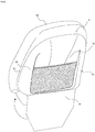
- Fig. 1 is a perspective view illustrating a state of a sound-absorbing material for vehicles 1 according to the embodiment seen from the surface.
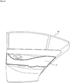
- Fig. 2 is a perspective view illustrating a state where the sound-absorbing material for vehicles 1 according to the embodiment is attached to a back side of a front seat 50 in a vehicle interior.
- a main body 10 is integrally formed to be attachable to a vehicle interior without providing an fixing hole in the surface.
- An approximate center of the main body 10 is provided with a sound-absorbing section 12 in which a predetermined airflow resistance is set.
- a thickness of a region shown by diagonal lines in Fig. 2 may be larger than a thickness of another region so that sound absorption characteristics of the region are different from those of the other region.
- the sound absorption characteristics are set so that sound absorption from conversation between passengers is inhibited, while absorbing another unpleasant noise in the vehicle.
- a rim section 14 is formed by compressing peripheral. Furthermore, in the rim section 14, a bent section 16 is formed, for example, by bending a side part and upper part of the main body 10.
- the bent section 16 formed in the side part and upper part of the main body 10 is fixed along the back side of the front seat 50 in accordance with roundness around a back surface of the front seat 50.
- the rim section 14 formed in a lower part of the main body 10 is bent downward from the front seat 50.
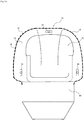
- Fig. 3 is a view illustrating a configuration of a back side of the sound-absorbing material for vehicles 1.
- the sound-absorbing section 12 is disposed in the approximate center of the main body 10 so that a region provided with a sound-absorbing function widens.
- a plurality of fixed parts 18 to be fixed to the front seat 50 are arranged, for example, via a space being from 50 to 220 mm.
- load is applied to the space between the fixed part 18 and the fixed part 18.
- a shape and structure of the fixed part 18 will be described later with reference to Fig. 5 .
- the rim section 14 is formed, by compression molding, to be continuous among the plurality of fixed parts 18, and the bent section 16 is formed. Furthermore, the sound-absorbing section 12 is provided adjacent to the rim section 14 via a stepped part on an inner side of the rim section 14, and among the plurality of fixed parts 18, to absorb sound of the vehicle interior. Additionally, to form the bent section 16, at least a part of the rim section 14 is bent almost along the stepped part so that the rim section is continuous among the plurality of fixed parts 18.
- Fig. 4 is a view schematically showing a cross section of the integrally formed main body 10.
- the main body 10 includes a configuration where, for example, a first fiber material 100, a second fiber material 102, PE powder 104 and a surface 106 are stacked and integrally formed.
- the first fiber material 100 is, for example, made of 900 g/m 2 of polyethylene terephthalate (PET).
- the second fiber material 102 is, for example, made of 200 g/m 2 of PET.
- the PE powder 104 is, for example, a powder body made of 100 g/m 2 of polyethylene (PE).
- the surface 106 is, for example, a surface material made of 150 g/m 2 of tricot or the like.
- Fig. 5 is a perspective view illustrating an outline of the fixed part 18.
- the fixed part 18 is, for example, made of plastic, and includes a configuration where an adhesive surface 182 is provided on a lower surface of a bonding protrusion 180.
- the bonding protrusion 180 is formed to be mechanically couplable to each of a plurality of bonding parts (not shown) provided on the back side of the front seat 50 by use of material elasticity without using any adhesives.
- the adhesive surface 182 is provided to fix the fixed part 18 to the rim section 14 of the sound-absorbing material for vehicles 1 with the adhesive.
- Fig. 6 is a view showing a cross-sectional structure of the main body 10.
- Fig. 6(a) is a view showing the cross-sectional structure along the A-A line shown in Fig. 3 .
- Fig. 6(b) is a view showing a cross-sectional structure along the B-B line shown in Fig. 3 .
- each of Figs. 7(a), (b) is an enlarged view of the rim section 14 in Fig. 6(a) .
- the sound-absorbing section 12 is not compressed, unlike the rim section 14, and is provided in the almost center of the main body 10, in which the predetermined airflow resistance is set. Furthermore, as shown in Fig. 6(b) , the sound-absorbing section 12 is not compressed, unlike the rim section 14, and the almost center of the main body 10 has a thickness larger than that of a corresponding part shown in Fig. 6(a) , and has sound absorption characteristics changed from those of the part shown in Fig. 6(a) .
- the rim section 14 is bent at a position X and a position Y, and has an end curved, to form the bent section 16.
- the bent section 16 is formed so that in a part bent at the position X, a ratio of an actual width (an actual length) L2 to a straight line distance width L1 is larger than 1 and smaller than 1.3. That is, in the bent section 16, a ratio of the actual width to a straight line distance width from the stepped part to an outer end of the rim section 14 is larger than 1 and smaller than 1.3.
- a plurality of stepped parts are provided, and a stepped part on a sound-absorbing section 12 side is higher than a stepped part on a rim section 14 side.
- the bent section 16 is formed so that in the parts bent at the position X and the position Y, the ratio of the actual width L2 to the straight line distance width L1 is larger than 1 and smaller than 1.3. That is, in a case where the bent section 16 is bent a plurality of times in a width direction, each of a ratio of the actual width L2 to the straight line distance width L1 in each bent part and a ratio of the actual width L2 to an overall straight line distance width L1 is set to be larger than 1 and smaller than 1.3.
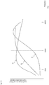
- Fig. 8 is a graph showing a result of measurement, by experiment, of a relation between the ratio of the actual width L2 to the straight line distance width L1 and a strength ratio of the rim section 14 in the sound-absorbing material for vehicles 1. Note that in Fig. 8 , a space between the fixed part 18 and the fixed part 18 that are provided in the rim section 14 is set to 58 mm, and this space of 58 mm is set as a space between fulcrums. Then, in a case where load is applied to the rim section 14, a displacement amount is measured.
- the strength 1
- a curve denoted with A in Fig. 8 shows a relation between the ratio of the actual width L2 to the straight line distance width L1 and the strength of the rim section 14, when the space between the fulcrums (the space between the fixed part 18 and the fixed part 18) is set to 58 mm.
- a curve denoted with B in Fig. 8 shows a relation between the ratio of the actual width L2 to the straight line distance width L1 and the strength of the rim section 14, when the space between the fulcrums is set to 40 mm.
- a curve denoted with C in Fig. 8 shows a relation between the ratio of the actual width L2 to the straight line distance width L1 and the strength of the rim section 14, when the space between the fulcrums is set to 200 mm.
- the rim section 14 tends to have the highest strength, when the ratio of the actual width L2 to the straight line distance width L1 is about 1.3, regardless of a length of the space between the fulcrums (the space between the fixed part 18 and the fixed part 18). Consequently, the rim section 14 is formed so that the ratio of the actual width L2 to the straight line distance width L1 is larger than 1 and smaller than 1.3.
- Fig. 9 is a view illustrating the position where the sound-absorbing material for vehicles is mounted, in the vehicle interior, in accordance with arrangement of the sound-absorbing section.
- the sound-absorbing section 12 provided on the almost center of the main body 10 is formed to be mounted to the vehicle interior within a range in which a vertical distance Elh downward from a lower surface of a head rest 500 of the front seat 50 is from 0.1 to 0.4 m.
- a sound-absorbing section 20 of the sound-absorbing material for vehicles is mounted to the vehicle interior within the range in which the vertical distance Elh downward from the lower surface of the head rest 500 of the front seat 50 is from 0.1 to 0.4 m.
- the sound-absorbing material for vehicles is provided on an inner side of a door or the like of the front seat 50, or a surface of a dashboard 54 between the dashboard 54 and the front seat 50, as shown in Fig.
- each of a sound-absorbing section 22 and a sound-absorbing section 30 of the sound-absorbing material for vehicles is mounted to the vehicle interior within the range in which the vertical distance Elh downward from the lower surface of the head rest 500 of the front seat 50 is from 0.1 to 0.4 m.
- the vertical distance Elh is set to be in the range from 0.1 to 0.4 m.
- the sound-absorbing section 12 is configured so that an airflow resistance AFR (Ns/m 3 ) and the vertical distance Elh (m) satisfy Equation (1) as follows. 210 ⁇ AFR + 10 / Elh ⁇ 3020
- the sound-absorbing material for vehicles 1 in the present application does not include a dash insulator 40 and a carpet 42.
- the dash insulator 40 provided between a boarding space of the vehicle interior and an engine compartment or the like, is hard for the passenger to see and hence is not provided with the surface 106. That is, the dash insulator is disposed at a position distant from positions of ears and a mouth of a general adult passenger.
- the carpet 42 is disposed at a position distant from the positions of the ears and mouth of the general adult passenger. Specifically, it is considered that the dash insulator 40 and the carpet 42 have a relatively low degree of influence on clarity in conversation between passengers.
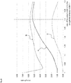
- Fig. 10 is a graph illustrating sound absorption characteristics of members arranged in the vehicle interior.
- a curve A shows sound absorption characteristics of the sound-absorbing section 12 that are set in a case where the vertical distance Elh is small and the airflow resistance AFR is 200 (Ns/m 3 ).
- a curve B shows sound absorption characteristics of the sound-absorbing section 12 that are set in a case where the vertical distance Elh is large and the airflow resistance AFR is 300 (Ns/m 3 ).
- a curve C shows sound absorption characteristics in a case where an airflow resistance AFR of the carpet 42 as a comparative example is 1500 (Ns/m 3 ) or more.
- the sound-absorbing section 12 is provided so that a sound absorption coefficient at a frequency of 1000 Hz or more is set to be higher than a sound absorption coefficient at a frequency that is less than 1000 Hz.
- a frequency band in which the degree of influence on the clarity in conversation between the passengers is large, is less than 1000 Hz.
- the frequency band of 1000 Hz or more includes a large amount of unnecessary sound in the vehicle interior, and hence the sound absorption coefficient is set to be high.
- each of the sound-absorbing section 12, the sound-absorbing section 20 and the sound-absorbing section 30 is disposed in the vehicle interior so that the vertical distance Elh is in the range from 0.1 to 0.4 m, and hence the sound-absorbing section is disposed in a predetermined region below the positions of the ears and mouth of the general adult passenger. Consequently, the sound absorption from the conversation between the passengers can be inhibited by the above described sound absorption characteristics, while another unnecessary sound in the vehicle interior can be absorbed.
- FIG. 11 is a view showing a configuration example of a first modification (a sound-absorbing material for vehicles 1a) of the sound-absorbing material for vehicles 1 seen from a back side.
- substantially the same configuration is denoted with the same reference sign.
- a fastener 19 is provided in an end portion of a bent section 16.
- the fastener 19 enables any member or a predetermined member to be detachably attached to each part that forms the sound-absorbing material for vehicles 1a.
- the fastener 19 is configured to replaceably and detachably attach a surface 106.
- Fig. 12 is a view showing a second modification (a sound-absorbing material for vehicles 2) of the sound-absorbing material for vehicles 1.
- the sound-absorbing material for vehicles 2 is mounted to, for example, a door 60 on a rear seat 52 side, and is configured to comprise a sound-absorbing section 20 shown in Fig. 9 .
- Fig. 13 is a view showing the modifications of the sound-absorbing section 12.
- Fig. 13(a) is a view showing a first modification (a sound-absorbing section 12a) of the sound-absorbing section 12.
- Fig. 13(b) is a view showing a second modification (a sound-absorbing section 12b) of the sound-absorbing section 12.
- the sound-absorbing section 12a includes a configuration where, for example, a third fiber material 108, a foam layer of hard urethane 110, PE powder 104 and a surface 106 are stacked and integrally formed.
- the third fiber material 108 is, for example, made of 1200 g/m 2 of PET.
- the hard urethane 110 is sandwiched between the third fiber material 108 and the surface 106, and has a thickness set to 5 mm or more and 15 mm or less. For example, the thickness of the hard urethane 110 is set to 10 mm.
- the sound-absorbing section 12b includes a configuration where, for example, a fourth fiber material 112, a foam layer of soft urethane 114, PE powder 104 and a surface 106 are stacked and integrally formed.
- the fourth fiber material 112 is, for example, made of 600 g/m 2 of PET.
- the soft urethane 114 is sandwiched between the fourth fiber material 112 and the surface 106, and has a thickness set to 5 mm or more and 15 mm or less.
- the thickness of the soft urethane 114 is set to 10 mm.
- each of the sound-absorbing section 12a and the sound-absorbing section 12b comprises urethane as the foam layer having a thickness of 5 mm or more, which is a member other than fiber and in which an airflow resistance has a predetermined value or more.
- the foam layer is not limited to urethane, as long as the layer can be formed of a well-known foam material.
- Fig. 14 is a view showing a third modification (a sound-absorbing section 12c) of the sound-absorbing section 12.
- the sound-absorbing section 12c includes a configuration where, for example, a fourth fiber material 112, PE powder 104 and a surface 106 are stacked and integrally formed.
- Fig. 15 is a view showing a fourth modification (a sound-absorbing section 12d) of the sound-absorbing section 12.
- the sound-absorbing section 12d includes a configuration where a non-breathable material 120 is stacked on a fourth fiber material 112 of a sound-absorbing section 12c, on a side opposite to the surface 106.
- the non-breathable material 120 is a non-breathable thin film.
- non-breathable material 120 may be provided to the sound-absorbing section 12a, the sound-absorbing section 12b or the sound-absorbing section 12c described above.
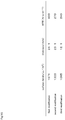
- Fig. 16 is a table showing the characteristics of the first modification to the third modification of the sound-absorbing section 12 (the sound-absorbing section 12a, the sound-absorbing section 12b, and the sound-absorbing section 12c).
- the sound-absorbing section 12a has a surface density of 1671 g/m 2 , a thickness of 24.1 mm, and an airflow resistance AFR of 900 Ns/m 3 .
- the sound-absorbing section 12b has a surface density of 1323 g/m 2 , a thickness of 23.1 mm, and an airflow resistance AFR of 270 Ns/m 3 .
- the sound-absorbing section 12c has a surface density of 1065 g/m 2 , a thickness of 12.1 mm, and an airflow resistance AFR of 240 Ns/m 3 .
- a sound-absorbing material for vehicles while utilizing design of the sound-absorbing material for vehicles, and improving clarity in conversation between a driver sitting in a front seat and a passenger sitting in a front seat next to the driver or in conversation between the passenger sitting in the front seat and a passenger sitting in a rear seat, unnecessary sound in a vehicle interior can be reduced.
Landscapes
- Engineering & Computer Science (AREA)
- Physics & Mathematics (AREA)
- Acoustics & Sound (AREA)
- Multimedia (AREA)
- Mechanical Engineering (AREA)
- Life Sciences & Earth Sciences (AREA)
- Wood Science & Technology (AREA)
- Vehicle Interior And Exterior Ornaments, Soundproofing, And Insulation (AREA)
- Soundproofing, Sound Blocking, And Sound Damping (AREA)
Abstract
Description
- The present invention relates to a sound-absorbing material for vehicles. Background
- It is known that in a vehicle such as an automobile, a sound-absorbing material is used for absorbing unpleasant noise, while designing an interior of the vehicle. Furthermore, a multilayer trim part for vehicles is known which comprises, for absorbing noise, a porous intermediate film layer between two fiber layers, and in which an overall airflow resistance (AFRoveraii in a unit of Ns/m3) and an overall density ρ (kg/m3) have a relation of 1500 < AFRoverall-10ρ < 3800 in a region having a thickness from 4 to 12.5 mm (e.g., see PTL 1).
- [PTL 1]
JP 2017-533142 A - In a conventional dash insulator or carpet, however, an airflow resistance is set to be rather high, to increase sound-absorbing effect, and the sound-absorbing effect is exerted even in a frequency band of conversation between passengers. Consequently, there is a problem that if a conventional sound-absorbing material that has high airflow resistance is disposed, for example, on a back surface of a front seat close to passenger's ears, a passengers in the vehicle less easy to have conversation between a passenger in a rear seat and a passenger in a front seat because of absorbing voice of the conversation.
- In view of the above problem, an object of the present invention is to provide a sound-absorbing material for vehicles that is capable of absorbing unpleasant noise in a vehicle interior while maintaining clear conversation between a passenger in a rear seat and a passenger in a front seat.
- To solve the above problem and achieve the object, a sound-absorbing material for vehicles according to an aspect of the present invention is mounted to a vehicle interior and comprises a main body in which at least a fiber material and a surface are integrally formed, wherein a sound-absorbing section provided in at least one part of the main body is formed to be mounted to the vehicle interior within a range in which a vertical distance Elh downward from a lower surface of a head rest of a front seat is from 0.1 to 0.4 m, and an airflow resistance AFR (Ns/m3) and the vertical distance Elh (m) satisfy a relation of: 210 < AFR+10/Elh < 3020.
- Furthermore, in the sound-absorbing material for vehicles according to the aspect of the present invention, in the sound-absorbing section, a non-ventilating material is applied on the fiber material on the opposite side of the surface.
- Additionally, in the sound-absorbing material for vehicles according to the aspect of the present invention, the non- ventilating material is a non- ventilating thin film.
- In addition, in the sound-absorbing material for vehicles according to the aspect of the present invention, the sound-absorbing section comprises a foam material such as urethane having a thickness of 5 mm or more and 15 mm or less between the fiber material and the surface material.
- Furthermore, in the sound-absorbing material for vehicles according to the aspect of the present invention, in the sound-absorbing section, a sound absorption coefficient at a frequency of 1000 Hz or more is set to be higher than a sound absorption coefficient at a frequency that is less than 1000 Hz.
- The present invention produces an effect that unpleasant noise in a vehicle interior can be absorbed, while maintaining clear conversation between a passenger in a rear seat and a passenger in a front seat.
-
- [
Fig. 1 ]
Fig. 1 is a perspective view illustrating a state of a sound-absorbing material for vehicles according to an embodiment seen from the surface. - [
Fig. 2 ]
Fig. 2 is a perspective view illustrating a state where the sound-absorbing material for vehicles according to the embodiment is assembled to a back side of a front seat in a vehicle. - [
Fig. 3 ]
Fig. 3 is a view illustrating a configuration of a back side of the sound-absorbing material for vehicles. - [
Fig. 4 ]
Fig. 4 is a view schematically showing a cross section of an integrally formed main body. - [
Fig. 5 ]
Fig. 5 is a perspective view illustrating an outline of a fixed part. - [
Fig. 6 ]
Fig. 6(a) is a view showing a cross-sectional structure along the A-A line shown inFig. 3 .Fig. 6(b) is a view showing a cross-sectional structure along the B-B line shown inFig. 3 . - [
Fig. 7 ]
Fig. 7(a) is a first enlarged view of a rim section inFig. 6(a) .Fig. 7(b) is a second enlarged view of the rim section inFig. 6(a) . - [
Fig. 8 ]
Fig. 8 is a graph showing a result of measurement, by experiment, of a relation between a ratio of an actual width to a distance and a ratio of a strength at the rim in the sound-absorbing material for vehicles. - [
Fig. 9 ]
Fig. 9 is a view illustrating a position where the sound-absorbing material for vehicles is mounted, in the vehicle, in accordance with arrangement of a sound-absorbing section. - [
Fig. 10 ]
Fig. 10 is a graph illustrating sound absorption characteristics of the sound-absorbing material. - [
Fig. 11 ]
Fig. 11 is a view showing a configuration example of a first modification of the sound-absorbing material for vehicles seen from a back side. - [
Fig. 12 ]
Fig. 12 is a view showing a second modification of the sound-absorbing material for vehicles. - [
Fig. 13 ]
Fig. 13(a) is a view showing a first modification of the sound-absorbing section.Fig. 13(b) is a view showing a second modification of the sound-absorbing section. - [
Fig. 14 ]
Fig. 14 is a view showing a third modification of the sound-absorbing section. - [
Fig. 15 ]
Fig. 15 is a view showing a fourth modification of the sound-absorbing section. - [
Fig. 16 ]
Fig. 16 is a table showing characteristics of the first modification to the third modification of the sound-absorbing section. - Hereinafter, an embodiment of a sound-absorbing material for vehicles will be described with reference to the drawings.
Fig. 1 is a perspective view illustrating a state of a sound-absorbing material forvehicles 1 according to the embodiment seen from the surface. Furthermore,Fig. 2 is a perspective view illustrating a state where the sound-absorbing material forvehicles 1 according to the embodiment is attached to a back side of afront seat 50 in a vehicle interior. - As shown in
Fig. 1 andFig. 2 , in the sound-absorbing material forvehicles 1, amain body 10 is integrally formed to be attachable to a vehicle interior without providing an fixing hole in the surface. An approximate center of themain body 10 is provided with a sound-absorbingsection 12 in which a predetermined airflow resistance is set. In the sound-absorbingsection 12, a thickness of a region shown by diagonal lines inFig. 2 may be larger than a thickness of another region so that sound absorption characteristics of the region are different from those of the other region. For example, in the sound-absorbingsection 12, the sound absorption characteristics are set so that sound absorption from conversation between passengers is inhibited, while absorbing another unpleasant noise in the vehicle. - Additionally, in the
main body 10, arim section 14 is formed by compressing peripheral. Furthermore, in therim section 14, abent section 16 is formed, for example, by bending a side part and upper part of themain body 10. - Then, in the sound-absorbing material for
vehicles 1, thebent section 16 formed in the side part and upper part of themain body 10 is fixed along the back side of thefront seat 50 in accordance with roundness around a back surface of thefront seat 50. Here, therim section 14 formed in a lower part of themain body 10 is bent downward from thefront seat 50. -
Fig. 3 is a view illustrating a configuration of a back side of the sound-absorbing material forvehicles 1. As shown inFig. 3 , the sound-absorbingsection 12 is disposed in the approximate center of themain body 10 so that a region provided with a sound-absorbing function widens. Furthermore, on a back side of therim section 14, a plurality of fixedparts 18 to be fixed to thefront seat 50 are arranged, for example, via a space being from 50 to 220 mm. Furthermore, when the sound-absorbing material forvehicles 1 is attached to thefront seat 50, load is applied to the space between thefixed part 18 and thefixed part 18. A shape and structure of the fixedpart 18 will be described later with reference toFig. 5 . Then, therim section 14 is formed, by compression molding, to be continuous among the plurality of fixedparts 18, and thebent section 16 is formed. Furthermore, the sound-absorbingsection 12 is provided adjacent to therim section 14 via a stepped part on an inner side of therim section 14, and among the plurality of fixedparts 18, to absorb sound of the vehicle interior. Additionally, to form thebent section 16, at least a part of therim section 14 is bent almost along the stepped part so that the rim section is continuous among the plurality of fixedparts 18. -
Fig. 4 is a view schematically showing a cross section of the integrally formedmain body 10. As shown inFig. 4 , themain body 10 includes a configuration where, for example, afirst fiber material 100, asecond fiber material 102,PE powder 104 and asurface 106 are stacked and integrally formed. - The
first fiber material 100 is, for example, made of 900 g/m2 of polyethylene terephthalate (PET). Thesecond fiber material 102 is, for example, made of 200 g/m2 of PET. ThePE powder 104 is, for example, a powder body made of 100 g/m2 of polyethylene (PE). Thesurface 106 is, for example, a surface material made of 150 g/m2 of tricot or the like. -
Fig. 5 is a perspective view illustrating an outline of the fixedpart 18. Thefixed part 18 is, for example, made of plastic, and includes a configuration where anadhesive surface 182 is provided on a lower surface of abonding protrusion 180. Thebonding protrusion 180 is formed to be mechanically couplable to each of a plurality of bonding parts (not shown) provided on the back side of thefront seat 50 by use of material elasticity without using any adhesives. Theadhesive surface 182 is provided to fix the fixedpart 18 to therim section 14 of the sound-absorbing material forvehicles 1 with the adhesive. - Next, a structure of the
main body 10 will be described in detail. -
Fig. 6 is a view showing a cross-sectional structure of themain body 10.Fig. 6(a) is a view showing the cross-sectional structure along the A-A line shown inFig. 3 .Fig. 6(b) is a view showing a cross-sectional structure along the B-B line shown inFig. 3 . Furthermore, each ofFigs. 7(a), (b) is an enlarged view of therim section 14 inFig. 6(a) . - As shown in
Fig. 6(a) , the sound-absorbingsection 12 is not compressed, unlike therim section 14, and is provided in the almost center of themain body 10, in which the predetermined airflow resistance is set. Furthermore, as shown inFig. 6(b) , the sound-absorbingsection 12 is not compressed, unlike therim section 14, and the almost center of themain body 10 has a thickness larger than that of a corresponding part shown inFig. 6(a) , and has sound absorption characteristics changed from those of the part shown inFig. 6(a) . - Additionally, the
rim section 14 is bent at a position X and a position Y, and has an end curved, to form thebent section 16. Here, as shown inFig. 7(a) , thebent section 16 is formed so that in a part bent at the position X, a ratio of an actual width (an actual length) L2 to a straight line distance width L1 is larger than 1 and smaller than 1.3. That is, in thebent section 16, a ratio of the actual width to a straight line distance width from the stepped part to an outer end of therim section 14 is larger than 1 and smaller than 1.3. A plurality of stepped parts are provided, and a stepped part on a sound-absorbingsection 12 side is higher than a stepped part on arim section 14 side. - Furthermore, as shown in
Fig. 7(b) , thebent section 16 is formed so that in the parts bent at the position X and the position Y, the ratio of the actual width L2 to the straight line distance width L1 is larger than 1 and smaller than 1.3. That is, in a case where thebent section 16 is bent a plurality of times in a width direction, each of a ratio of the actual width L2 to the straight line distance width L1 in each bent part and a ratio of the actual width L2 to an overall straight line distance width L1 is set to be larger than 1 and smaller than 1.3. -
Fig. 8 is a graph showing a result of measurement, by experiment, of a relation between the ratio of the actual width L2 to the straight line distance width L1 and a strength ratio of therim section 14 in the sound-absorbing material forvehicles 1. Note that inFig. 8 , a space between thefixed part 18 and thefixed part 18 that are provided in therim section 14 is set to 58 mm, and this space of 58 mm is set as a space between fulcrums. Then, in a case where load is applied to therim section 14, a displacement amount is measured. In this case, a strength at a time when the ratio of the actual width L2 to the straight line distance width L1 is 1 is used as a reference (the strength = 1), and the strength ratio of therim section 14 is indicated. Here, it is indicated that when the ratio of the actual width L2 to the straight line distance width L1 is 1, therim section 14 is not bent and is planar. - Therefore, a curve denoted with A in
Fig. 8 shows a relation between the ratio of the actual width L2 to the straight line distance width L1 and the strength of therim section 14, when the space between the fulcrums (the space between thefixed part 18 and the fixed part 18) is set to 58 mm. Furthermore, a curve denoted with B inFig. 8 shows a relation between the ratio of the actual width L2 to the straight line distance width L1 and the strength of therim section 14, when the space between the fulcrums is set to 40 mm. Additionally, a curve denoted with C inFig. 8 shows a relation between the ratio of the actual width L2 to the straight line distance width L1 and the strength of therim section 14, when the space between the fulcrums is set to 200 mm. - As shown in
Fig. 8 , it is confirmed that therim section 14 tends to have the highest strength, when the ratio of the actual width L2 to the straight line distance width L1 is about 1.3, regardless of a length of the space between the fulcrums (the space between thefixed part 18 and the fixed part 18). Consequently, therim section 14 is formed so that the ratio of the actual width L2 to the straight line distance width L1 is larger than 1 and smaller than 1.3. - Next, description will be made as to a position where the sound-absorbing material for
vehicles 1 is mounted, in the vehicle interior, and sound absorption characteristics of the sound-absorbing material forvehicles 1. -
Fig. 9 is a view illustrating the position where the sound-absorbing material for vehicles is mounted, in the vehicle interior, in accordance with arrangement of the sound-absorbing section. For example, in the sound-absorbing material forvehicles 1 shown inFig. 1 , the sound-absorbingsection 12 provided on the almost center of themain body 10 is formed to be mounted to the vehicle interior within a range in which a vertical distance Elh downward from a lower surface of ahead rest 500 of thefront seat 50 is from 0.1 to 0.4 m. - Furthermore, also in a case where the sound-absorbing material for vehicles is provided on an inner side of a door or the like on a
rear seat 52 side between thefront seat 50 and therear seat 52, a sound-absorbingsection 20 of the sound-absorbing material for vehicles is mounted to the vehicle interior within the range in which the vertical distance Elh downward from the lower surface of thehead rest 500 of thefront seat 50 is from 0.1 to 0.4 m. Additionally, also in a case where the sound-absorbing material for vehicles is provided on an inner side of a door or the like of thefront seat 50, or a surface of adashboard 54 between thedashboard 54 and thefront seat 50, as shown inFig. 9 , each of a sound-absorbingsection 22 and a sound-absorbingsection 30 of the sound-absorbing material for vehicles is mounted to the vehicle interior within the range in which the vertical distance Elh downward from the lower surface of thehead rest 500 of thefront seat 50 is from 0.1 to 0.4 m. - Furthermore, if backrest parts of the
front seat 50 and therear seat 52 are stood vertically or reclined and inclination of each backrest is changed, for example, in a range from about 0 to 30 degrees, a position of thehead rest 500 or ahead rest 520 varies. Even in this case, the vertical distance Elh is set to be in the range from 0.1 to 0.4 m. - Additionally, the sound-absorbing
section 12 is configured so that an airflow resistance AFR (Ns/m3) and the vertical distance Elh (m) satisfy Equation (1) as follows.
vehicles 1 in the present application does not include adash insulator 40 and acarpet 42. This is because thedash insulator 40, provided between a boarding space of the vehicle interior and an engine compartment or the like, is hard for the passenger to see and hence is not provided with thesurface 106. That is, the dash insulator is disposed at a position distant from positions of ears and a mouth of a general adult passenger. Also, thecarpet 42 is disposed at a position distant from the positions of the ears and mouth of the general adult passenger. Specifically, it is considered that thedash insulator 40 and thecarpet 42 have a relatively low degree of influence on clarity in conversation between passengers. -
Fig. 10 is a graph illustrating sound absorption characteristics of members arranged in the vehicle interior. InFig. 10 , a curve A shows sound absorption characteristics of the sound-absorbingsection 12 that are set in a case where the vertical distance Elh is small and the airflow resistance AFR is 200 (Ns/m3). Furthermore, a curve B shows sound absorption characteristics of the sound-absorbingsection 12 that are set in a case where the vertical distance Elh is large and the airflow resistance AFR is 300 (Ns/m3). Additionally, a curve C shows sound absorption characteristics in a case where an airflow resistance AFR of thecarpet 42 as a comparative example is 1500 (Ns/m3) or more. - As shown in
Fig. 10 , the sound-absorbingsection 12 is provided so that a sound absorption coefficient at a frequency of 1000 Hz or more is set to be higher than a sound absorption coefficient at a frequency that is less than 1000 Hz. Here, this is because it is considered that a frequency band, in which the degree of influence on the clarity in conversation between the passengers is large, is less than 1000 Hz. Furthermore, it is considered that the frequency band of 1000 Hz or more includes a large amount of unnecessary sound in the vehicle interior, and hence the sound absorption coefficient is set to be high. - Thus, each of the sound-absorbing
section 12, the sound-absorbingsection 20 and the sound-absorbingsection 30 is disposed in the vehicle interior so that the vertical distance Elh is in the range from 0.1 to 0.4 m, and hence the sound-absorbing section is disposed in a predetermined region below the positions of the ears and mouth of the general adult passenger. Consequently, the sound absorption from the conversation between the passengers can be inhibited by the above described sound absorption characteristics, while another unnecessary sound in the vehicle interior can be absorbed. - Next, modifications of the sound-absorbing material for
vehicles 1 will be described.Fig. 11 is a view showing a configuration example of a first modification (a sound-absorbing material forvehicles 1a) of the sound-absorbing material forvehicles 1 seen from a back side. Hereinafter, substantially the same configuration is denoted with the same reference sign. - As shown in
Fig. 11 , in the sound-absorbing material forvehicles 1a, afastener 19 is provided in an end portion of abent section 16. Thefastener 19 enables any member or a predetermined member to be detachably attached to each part that forms the sound-absorbing material forvehicles 1a. For example, thefastener 19 is configured to replaceably and detachably attach asurface 106. -
Fig. 12 is a view showing a second modification (a sound-absorbing material for vehicles 2) of the sound-absorbing material forvehicles 1. As shown inFig. 12 , the sound-absorbing material forvehicles 2 is mounted to, for example, adoor 60 on arear seat 52 side, and is configured to comprise a sound-absorbingsection 20 shown inFig. 9 . - Next, modifications of the sound-absorbing
section 12 will be described. -
Fig. 13 is a view showing the modifications of the sound-absorbingsection 12.Fig. 13(a) is a view showing a first modification (a sound-absorbingsection 12a) of the sound-absorbingsection 12.Fig. 13(b) is a view showing a second modification (a sound-absorbingsection 12b) of the sound-absorbingsection 12. - As shown in
Fig. 13(a) , the sound-absorbingsection 12a includes a configuration where, for example, athird fiber material 108, a foam layer ofhard urethane 110,PE powder 104 and asurface 106 are stacked and integrally formed. - The
third fiber material 108 is, for example, made of 1200 g/m2 of PET. Thehard urethane 110 is sandwiched between thethird fiber material 108 and thesurface 106, and has a thickness set to 5 mm or more and 15 mm or less. For example, the thickness of thehard urethane 110 is set to 10 mm. - As shown in
Fig. 13(b) , the sound-absorbingsection 12b includes a configuration where, for example, afourth fiber material 112, a foam layer ofsoft urethane 114,PE powder 104 and asurface 106 are stacked and integrally formed. - The
fourth fiber material 112 is, for example, made of 600 g/m2 of PET. Thesoft urethane 114 is sandwiched between thefourth fiber material 112 and thesurface 106, and has a thickness set to 5 mm or more and 15 mm or less. For example, the thickness of thesoft urethane 114 is set to 10 mm. - Note that each of the sound-absorbing
section 12a and the sound-absorbingsection 12b comprises urethane as the foam layer having a thickness of 5 mm or more, which is a member other than fiber and in which an airflow resistance has a predetermined value or more. This is because, for example, if the thickness of urethane is from 1 to 2 mm, i.e., less than 5 mm, the airflow resistance is small, and influence on acoustic characteristics is small. Note that the foam layer is not limited to urethane, as long as the layer can be formed of a well-known foam material. -
Fig. 14 is a view showing a third modification (a sound-absorbingsection 12c) of the sound-absorbingsection 12. As shown inFig. 14 , the sound-absorbingsection 12c includes a configuration where, for example, afourth fiber material 112,PE powder 104 and asurface 106 are stacked and integrally formed. -
Fig. 15 is a view showing a fourth modification (a sound-absorbingsection 12d) of the sound-absorbingsection 12. As shown inFig. 15 , the sound-absorbingsection 12d includes a configuration where anon-breathable material 120 is stacked on afourth fiber material 112 of a sound-absorbingsection 12c, on a side opposite to thesurface 106. For example, thenon-breathable material 120 is a non-breathable thin film. - Note that the
non-breathable material 120 may be provided to the sound-absorbingsection 12a, the sound-absorbingsection 12b or the sound-absorbingsection 12c described above. - Next, description will be made as to characteristics of the first modification to the third modification of the sound-absorbing section 12 (the sound-absorbing
section 12a, the sound-absorbingsection 12b, and the sound-absorbingsection 12c). -
Fig. 16 is a table showing the characteristics of the first modification to the third modification of the sound-absorbing section 12 (the sound-absorbingsection 12a, the sound-absorbingsection 12b, and the sound-absorbingsection 12c). As shown inFig. 16 , the sound-absorbingsection 12a has a surface density of 1671 g/m2, a thickness of 24.1 mm, and an airflow resistance AFR of 900 Ns/m3. The sound-absorbingsection 12b has a surface density of 1323 g/m2, a thickness of 23.1 mm, and an airflow resistance AFR of 270 Ns/m3. The sound-absorbingsection 12c has a surface density of 1065 g/m2, a thickness of 12.1 mm, and an airflow resistance AFR of 240 Ns/m3. - Thus, in a sound-absorbing material for vehicles according to one embodiment, while utilizing design of the sound-absorbing material for vehicles, and improving clarity in conversation between a driver sitting in a front seat and a passenger sitting in a front seat next to the driver or in conversation between the passenger sitting in the front seat and a passenger sitting in a rear seat, unnecessary sound in a vehicle interior can be reduced.
-
- 1, 1a, and 2
- Sound-absorbing material for vehicles
- 10
- Main body
- 12, 12a, 12b, 12c, 12d, 20, 22, and 30
- Sound-absorbing section
- 14
- rim section
- 16
- Bent section
- 18
- Fixed part
- 19
- Fastener
- 50
- Front seat
- 52
- Rear seat
- 54
- Dashboard
- 100
- First fiber material
- 102
- Second fiber material
- 104
- PE powder
- 106
- Surface
- 108
- Third fiber material
- 110
- Hard urethane
- 112
- Fourth fiber material
- 114
- Soft urethane
- 120
- Non-breathable material
- 180
- Bonding protrusion
- 182
- Adhesive surface
- 500 and 520
- Head rest
Claims (5)
- A sound-absorbing material for vehicles that is mounted to a vehicle interior and comprises a main body in which at least a fiber material and a surface material are integrally formed, wherein a sound-absorbing section provided in at least a part of the main body is formed to be mounted to the vehicle interior within a range in which a vertical distance Elh downward from a lower surface of a head rest of a front seat is from 0.1 to 0.4 m, and an airflow resistance AFR (Ns/m3) and the vertical distance Elh (m) satisfy a relation of:

- The sound-absorbing material for vehicles according to claim 1, wherein in the sound-absorbing section,
a non-breathable material is stacked on the fiber material on a side opposite to the surface material. - The sound-absorbing material for vehicles according to claim 2, wherein the non-breathable material is a non-breathable thin film.
- The sound-absorbing material for vehicles according to any one of claims 1 to 3, wherein the sound-absorbing section comprises a foam layer having a thickness of 5 mm or more and 15 mm or less between the fiber material and the surface material.
- The sound-absorbing material for vehicles according to any one of claims 1 to 4, wherein in the sound-absorbing section,
a sound absorption coefficient at a frequency of 1000 Hz or more is set to be higher than a sound absorption coefficient at a frequency that is less than 1000 Hz.
Applications Claiming Priority (2)
| Application Number | Priority Date | Filing Date | Title |
|---|---|---|---|
| JP2018167670 | 2018-09-07 | ||
| PCT/JP2019/018633 WO2020049797A1 (en) | 2018-09-07 | 2019-05-09 | Sound-absorbing material for vehicles |
Publications (3)
| Publication Number | Publication Date |
|---|---|
| EP3848249A1 true EP3848249A1 (en) | 2021-07-14 |
| EP3848249A4 EP3848249A4 (en) | 2022-06-08 |
| EP3848249B1 EP3848249B1 (en) | 2025-01-22 |
Family
ID=69721925
Family Applications (1)
| Application Number | Title | Priority Date | Filing Date |
|---|---|---|---|
| EP19858613.3A Active EP3848249B1 (en) | 2018-09-07 | 2019-05-09 | Sound-absorbing material for vehicles |
Country Status (8)
| Country | Link |
|---|---|
| US (1) | US11945379B2 (en) |
| EP (1) | EP3848249B1 (en) |
| JP (2) | JP7157163B2 (en) |
| KR (1) | KR20210035889A (en) |
| CN (1) | CN112638717B (en) |
| ES (1) | ES3009307T3 (en) |
| MX (1) | MX2021002177A (en) |
| WO (1) | WO2020049797A1 (en) |
Families Citing this family (1)
| Publication number | Priority date | Publication date | Assignee | Title |
|---|---|---|---|---|
| JP7791671B2 (en) * | 2021-09-02 | 2025-12-24 | 小島プレス工業株式会社 | sound absorbing device |
Family Cites Families (27)
| Publication number | Priority date | Publication date | Assignee | Title |
|---|---|---|---|---|
| SE383646B (en) * | 1974-05-30 | 1976-03-22 | Reduc Acoustics Ab | CONSTRUCTION WITH PARTIAL DAMPING LAYER |
| JPS5426219U (en) * | 1977-07-25 | 1979-02-21 | ||
| WO1998018656A1 (en) * | 1996-10-29 | 1998-05-07 | Rieter Automotive (International) Ag | Ultralight, multifunctional, sound-insulating material assembly |
| JP3367637B2 (en) * | 1997-10-16 | 2003-01-14 | 日産自動車株式会社 | Sound insulation structure in the car interior |
| JP2003316366A (en) | 2002-04-23 | 2003-11-07 | Suzuki Motor Corp | Sound absorbing material and method of manufacturing the same |
| US20040131836A1 (en) * | 2003-01-02 | 2004-07-08 | 3M Innovative Properties Company | Acoustic web |
| US7320739B2 (en) | 2003-01-02 | 2008-01-22 | 3M Innovative Properties Company | Sound absorptive multilayer composite |
| US7959213B2 (en) * | 2003-10-29 | 2011-06-14 | Aplix | Door panel with self-gripping hooks |
| DE102004001081B4 (en) * | 2004-01-05 | 2013-02-14 | Airbus Operations Gmbh | Insulation structure for the internal insulation of a vehicle |
| JP2006160177A (en) | 2004-12-10 | 2006-06-22 | Hayashi Engineering Inc | Sound absorbing structure of automobile running on road |
| WO2005084978A1 (en) | 2004-03-05 | 2005-09-15 | Hayashi Engineering Inc. | Sunvisor for automobile and sound absorbing structure of automobile running on road |
| JP4406871B2 (en) | 2004-03-08 | 2010-02-03 | マツダ株式会社 | Sound absorption structure of automobile |
| US20080302049A1 (en) * | 2007-06-08 | 2008-12-11 | Kathleen Antoinette Stoneburner | Insulated fabric pocket panels |
| JP5056248B2 (en) * | 2007-08-06 | 2012-10-24 | マツダ株式会社 | Sound absorbing structure with sound absorbing material |
| US7677660B2 (en) * | 2007-09-06 | 2010-03-16 | Lear Corporation | Acoustically tuned seating assembly |
| JP2009126496A (en) | 2007-11-28 | 2009-06-11 | Toyota Boshoku Corp | Vehicular interior material and manufacturing method for vehicular interior material |
| JP5421758B2 (en) * | 2009-12-14 | 2014-02-19 | 本田技研工業株式会社 | Bulkhead for vehicle |
| KR20110108011A (en) | 2010-03-26 | 2011-10-05 | 신준식 | Car Multifunctional Assist Cushion |
| EP2593614B1 (en) * | 2010-07-13 | 2016-04-13 | Bellmax Acoustic Pty Ltd | An acoustic panel |
| US20150034414A1 (en) * | 2012-07-04 | 2015-02-05 | Nishikawa Rubber Co., Ltd. | Sound insulation material |
| JP6111460B2 (en) * | 2013-07-10 | 2017-04-12 | 名古屋油化株式会社 | Sound absorbing material and molded material of sound absorbing material |
| JP6186629B2 (en) * | 2014-01-20 | 2017-08-30 | 名古屋油化株式会社 | Sound-absorbing interior material |
| JP6484408B2 (en) | 2014-06-24 | 2019-03-13 | ニチアス株式会社 | Soundproof material and method of manufacturing soundproof cover |
| JP6486034B2 (en) * | 2014-08-26 | 2019-03-20 | 太進工業株式会社 | COMPOSITE SOUND ABSORBING MATERIAL, MANUFACTURING METHOD THEREOF, |
| EP3015314B1 (en) | 2014-10-30 | 2017-08-23 | Autoneum Management AG | Light weight acoustic trim part |
| EP3368295A1 (en) | 2015-10-30 | 2018-09-05 | Adient Luxembourg Holding S.à r.l. | Cover and method for producing a cover |
| KR20170077985A (en) | 2015-12-29 | 2017-07-07 | (주) 금토일산업 | Sound absorbing-excluding sheet for auto wheel guard and method of manufacturing thereof |
-
2019
- 2019-05-09 KR KR1020217006042A patent/KR20210035889A/en not_active Ceased
- 2019-05-09 EP EP19858613.3A patent/EP3848249B1/en active Active
- 2019-05-09 US US17/270,651 patent/US11945379B2/en active Active
- 2019-05-09 WO PCT/JP2019/018633 patent/WO2020049797A1/en not_active Ceased
- 2019-05-09 JP JP2020541011A patent/JP7157163B2/en active Active
- 2019-05-09 CN CN201980055640.3A patent/CN112638717B/en active Active
- 2019-05-09 MX MX2021002177A patent/MX2021002177A/en unknown
- 2019-05-09 ES ES19858613T patent/ES3009307T3/en active Active
-
2022
- 2022-10-06 JP JP2022161492A patent/JP7304122B2/en active Active
Also Published As
| Publication number | Publication date |
|---|---|
| EP3848249A4 (en) | 2022-06-08 |
| EP3848249B1 (en) | 2025-01-22 |
| MX2021002177A (en) | 2021-04-28 |
| KR20210035889A (en) | 2021-04-01 |
| CN112638717A (en) | 2021-04-09 |
| JP2022191344A (en) | 2022-12-27 |
| US11945379B2 (en) | 2024-04-02 |
| JPWO2020049797A1 (en) | 2021-08-26 |
| ES3009307T3 (en) | 2025-03-26 |
| JP7304122B2 (en) | 2023-07-06 |
| JP7157163B2 (en) | 2022-10-19 |
| CN112638717B (en) | 2025-02-11 |
| US20210245682A1 (en) | 2021-08-12 |
| WO2020049797A1 (en) | 2020-03-12 |
Similar Documents
| Publication | Publication Date | Title |
|---|---|---|
| JP5120620B2 (en) | Door trim | |
| US9088842B2 (en) | Grille for electroacoustic transducer | |
| US20050140199A1 (en) | Padding for the seat proper of a vehicle seat and a seat proper equipped with such padding | |
| JP7040317B2 (en) | Seat back structure | |
| JP7124304B2 (en) | vehicle seat | |
| JP2009247388A (en) | Headrest | |
| JP7054930B2 (en) | Vehicle interior materials | |
| US20170320415A1 (en) | Lightweight Seat for Vehicles | |
| WO2015111559A1 (en) | Seat for vehicle | |
| EP3848249A1 (en) | Sound-absorbing material for vehicles | |
| JP2017035904A (en) | Vehicle seat | |
| US7931951B2 (en) | Carpet for vehicle and method for manufacturing same | |
| JP2008201193A (en) | Armrest for vehicle | |
| CN210554526U (en) | Storage device for vehicle and garnish for vehicle | |
| JPH09117346A (en) | Seat cushion suspension structure | |
| US11505103B2 (en) | Vehicle privacy screen | |
| KR20220161571A (en) | Strength-reinforced dash insulation for vehicles | |
| JP4197138B2 (en) | Vehicle armrest | |
| WO2020049798A1 (en) | Sound-absorbing material for vehicles | |
| JP6965113B2 (en) | Seat pad for vehicles | |
| US12441093B2 (en) | Vehicular interior material and seat back panel | |
| JP4269845B2 (en) | Vehicle armrest structure | |
| JPH10166864A (en) | Arm rest pad | |
| JPH0857172A (en) | Buffer structure in interior parts | |
| KR101395602B1 (en) | Apparatus of seat for vehicle |
Legal Events
| Date | Code | Title | Description |
|---|---|---|---|
| STAA | Information on the status of an ep patent application or granted ep patent |
Free format text: STATUS: THE INTERNATIONAL PUBLICATION HAS BEEN MADE |
|
| PUAI | Public reference made under article 153(3) epc to a published international application that has entered the european phase |
Free format text: ORIGINAL CODE: 0009012 |
|
| STAA | Information on the status of an ep patent application or granted ep patent |
Free format text: STATUS: REQUEST FOR EXAMINATION WAS MADE |
|
| 17P | Request for examination filed |
Effective date: 20210222 |
|
| AK | Designated contracting states |
Kind code of ref document: A1 Designated state(s): AL AT BE BG CH CY CZ DE DK EE ES FI FR GB GR HR HU IE IS IT LI LT LU LV MC MK MT NL NO PL PT RO RS SE SI SK SM TR |
|
| DAV | Request for validation of the european patent (deleted) | ||
| DAX | Request for extension of the european patent (deleted) | ||
| A4 | Supplementary search report drawn up and despatched |
Effective date: 20220506 |
|
| RIC1 | Information provided on ipc code assigned before grant |
Ipc: G10K 11/168 20060101ALI20220429BHEP Ipc: G10K 11/16 20060101ALI20220429BHEP Ipc: B60R 13/08 20060101AFI20220429BHEP |
|
| STAA | Information on the status of an ep patent application or granted ep patent |
Free format text: STATUS: EXAMINATION IS IN PROGRESS |
|
| 17Q | First examination report despatched |
Effective date: 20230630 |
|
| RAP3 | Party data changed (applicant data changed or rights of an application transferred) |
Owner name: MT-TEC LLC |
|
| RAP1 | Party data changed (applicant data changed or rights of an application transferred) |
Owner name: KOTOBUKIYA FRONTE CO., LTD. |
|
| GRAP | Despatch of communication of intention to grant a patent |
Free format text: ORIGINAL CODE: EPIDOSNIGR1 |
|
| STAA | Information on the status of an ep patent application or granted ep patent |
Free format text: STATUS: GRANT OF PATENT IS INTENDED |
|
| INTG | Intention to grant announced |
Effective date: 20241108 |
|
| GRAS | Grant fee paid |
Free format text: ORIGINAL CODE: EPIDOSNIGR3 |
|
| GRAA | (expected) grant |
Free format text: ORIGINAL CODE: 0009210 |
|
| STAA | Information on the status of an ep patent application or granted ep patent |
Free format text: STATUS: THE PATENT HAS BEEN GRANTED |
|
| AK | Designated contracting states |
Kind code of ref document: B1 Designated state(s): AL AT BE BG CH CY CZ DE DK EE ES FI FR GB GR HR HU IE IS IT LI LT LU LV MC MK MT NL NO PL PT RO RS SE SI SK SM TR |
|
| REG | Reference to a national code |
Ref country code: GB Ref legal event code: FG4D |
|
| REG | Reference to a national code |
Ref country code: CH Ref legal event code: EP |
|
| REG | Reference to a national code |
Ref country code: IE Ref legal event code: FG4D |
|
| REG | Reference to a national code |
Ref country code: DE Ref legal event code: R096 Ref document number: 602019065214 Country of ref document: DE |
|
| REG | Reference to a national code |
Ref country code: ES Ref legal event code: FG2A Ref document number: 3009307 Country of ref document: ES Kind code of ref document: T3 Effective date: 20250326 |
|
| REG | Reference to a national code |
Ref country code: NL Ref legal event code: MP Effective date: 20250122 |
|
| PG25 | Lapsed in a contracting state [announced via postgrant information from national office to epo] |
Ref country code: NL Free format text: LAPSE BECAUSE OF FAILURE TO SUBMIT A TRANSLATION OF THE DESCRIPTION OR TO PAY THE FEE WITHIN THE PRESCRIBED TIME-LIMIT Effective date: 20250122 |
|
| PG25 | Lapsed in a contracting state [announced via postgrant information from national office to epo] |
Ref country code: RS Free format text: LAPSE BECAUSE OF FAILURE TO SUBMIT A TRANSLATION OF THE DESCRIPTION OR TO PAY THE FEE WITHIN THE PRESCRIBED TIME-LIMIT Effective date: 20250422 |
|
| PG25 | Lapsed in a contracting state [announced via postgrant information from national office to epo] |
Ref country code: FI Free format text: LAPSE BECAUSE OF FAILURE TO SUBMIT A TRANSLATION OF THE DESCRIPTION OR TO PAY THE FEE WITHIN THE PRESCRIBED TIME-LIMIT Effective date: 20250122 |
|
| PG25 | Lapsed in a contracting state [announced via postgrant information from national office to epo] |
Ref country code: PL Free format text: LAPSE BECAUSE OF FAILURE TO SUBMIT A TRANSLATION OF THE DESCRIPTION OR TO PAY THE FEE WITHIN THE PRESCRIBED TIME-LIMIT Effective date: 20250122 |
|
| PGFP | Annual fee paid to national office [announced via postgrant information from national office to epo] |
Ref country code: DE Payment date: 20250520 Year of fee payment: 7 |
|
| PGFP | Annual fee paid to national office [announced via postgrant information from national office to epo] |
Ref country code: GB Payment date: 20250522 Year of fee payment: 7 Ref country code: ES Payment date: 20250616 Year of fee payment: 7 |
|
| REG | Reference to a national code |
Ref country code: LT Ref legal event code: MG9D |
|
| PG25 | Lapsed in a contracting state [announced via postgrant information from national office to epo] |
Ref country code: IS Free format text: LAPSE BECAUSE OF FAILURE TO SUBMIT A TRANSLATION OF THE DESCRIPTION OR TO PAY THE FEE WITHIN THE PRESCRIBED TIME-LIMIT Effective date: 20250522 Ref country code: NO Free format text: LAPSE BECAUSE OF FAILURE TO SUBMIT A TRANSLATION OF THE DESCRIPTION OR TO PAY THE FEE WITHIN THE PRESCRIBED TIME-LIMIT Effective date: 20250422 |
|
| REG | Reference to a national code |
Ref country code: AT Ref legal event code: MK05 Ref document number: 1761256 Country of ref document: AT Kind code of ref document: T Effective date: 20250122 |
|
| PG25 | Lapsed in a contracting state [announced via postgrant information from national office to epo] |
Ref country code: HR Free format text: LAPSE BECAUSE OF FAILURE TO SUBMIT A TRANSLATION OF THE DESCRIPTION OR TO PAY THE FEE WITHIN THE PRESCRIBED TIME-LIMIT Effective date: 20250122 |
|
| PG25 | Lapsed in a contracting state [announced via postgrant information from national office to epo] |
Ref country code: PT Free format text: LAPSE BECAUSE OF FAILURE TO SUBMIT A TRANSLATION OF THE DESCRIPTION OR TO PAY THE FEE WITHIN THE PRESCRIBED TIME-LIMIT Effective date: 20250522 Ref country code: LV Free format text: LAPSE BECAUSE OF FAILURE TO SUBMIT A TRANSLATION OF THE DESCRIPTION OR TO PAY THE FEE WITHIN THE PRESCRIBED TIME-LIMIT Effective date: 20250122 |
|
| PGFP | Annual fee paid to national office [announced via postgrant information from national office to epo] |
Ref country code: FR Payment date: 20250521 Year of fee payment: 7 |
|
| PG25 | Lapsed in a contracting state [announced via postgrant information from national office to epo] |
Ref country code: GR Free format text: LAPSE BECAUSE OF FAILURE TO SUBMIT A TRANSLATION OF THE DESCRIPTION OR TO PAY THE FEE WITHIN THE PRESCRIBED TIME-LIMIT Effective date: 20250423 Ref country code: BG Free format text: LAPSE BECAUSE OF FAILURE TO SUBMIT A TRANSLATION OF THE DESCRIPTION OR TO PAY THE FEE WITHIN THE PRESCRIBED TIME-LIMIT Effective date: 20250122 |
|
| PG25 | Lapsed in a contracting state [announced via postgrant information from national office to epo] |
Ref country code: AT Free format text: LAPSE BECAUSE OF FAILURE TO SUBMIT A TRANSLATION OF THE DESCRIPTION OR TO PAY THE FEE WITHIN THE PRESCRIBED TIME-LIMIT Effective date: 20250122 |
|
| PG25 | Lapsed in a contracting state [announced via postgrant information from national office to epo] |
Ref country code: SE Free format text: LAPSE BECAUSE OF FAILURE TO SUBMIT A TRANSLATION OF THE DESCRIPTION OR TO PAY THE FEE WITHIN THE PRESCRIBED TIME-LIMIT Effective date: 20250122 |
|
| PG25 | Lapsed in a contracting state [announced via postgrant information from national office to epo] |
Ref country code: SM Free format text: LAPSE BECAUSE OF FAILURE TO SUBMIT A TRANSLATION OF THE DESCRIPTION OR TO PAY THE FEE WITHIN THE PRESCRIBED TIME-LIMIT Effective date: 20250122 |
|
| PG25 | Lapsed in a contracting state [announced via postgrant information from national office to epo] |
Ref country code: DK Free format text: LAPSE BECAUSE OF FAILURE TO SUBMIT A TRANSLATION OF THE DESCRIPTION OR TO PAY THE FEE WITHIN THE PRESCRIBED TIME-LIMIT Effective date: 20250122 |
|
| PG25 | Lapsed in a contracting state [announced via postgrant information from national office to epo] |
Ref country code: IT Free format text: LAPSE BECAUSE OF FAILURE TO SUBMIT A TRANSLATION OF THE DESCRIPTION OR TO PAY THE FEE WITHIN THE PRESCRIBED TIME-LIMIT Effective date: 20250122 |
|
| PG25 | Lapsed in a contracting state [announced via postgrant information from national office to epo] |
Ref country code: CZ Free format text: LAPSE BECAUSE OF FAILURE TO SUBMIT A TRANSLATION OF THE DESCRIPTION OR TO PAY THE FEE WITHIN THE PRESCRIBED TIME-LIMIT Effective date: 20250122 Ref country code: EE Free format text: LAPSE BECAUSE OF FAILURE TO SUBMIT A TRANSLATION OF THE DESCRIPTION OR TO PAY THE FEE WITHIN THE PRESCRIBED TIME-LIMIT Effective date: 20250122 |
|
| REG | Reference to a national code |
Ref country code: DE Ref legal event code: R097 Ref document number: 602019065214 Country of ref document: DE |
|
| PG25 | Lapsed in a contracting state [announced via postgrant information from national office to epo] |
Ref country code: RO Free format text: LAPSE BECAUSE OF FAILURE TO SUBMIT A TRANSLATION OF THE DESCRIPTION OR TO PAY THE FEE WITHIN THE PRESCRIBED TIME-LIMIT Effective date: 20250122 |
|
| PG25 | Lapsed in a contracting state [announced via postgrant information from national office to epo] |
Ref country code: SK Free format text: LAPSE BECAUSE OF FAILURE TO SUBMIT A TRANSLATION OF THE DESCRIPTION OR TO PAY THE FEE WITHIN THE PRESCRIBED TIME-LIMIT Effective date: 20250122 |
|
| PLBE | No opposition filed within time limit |
Free format text: ORIGINAL CODE: 0009261 |
|
| STAA | Information on the status of an ep patent application or granted ep patent |
Free format text: STATUS: NO OPPOSITION FILED WITHIN TIME LIMIT |
|
| REG | Reference to a national code |
Ref country code: CH Ref legal event code: L10 Free format text: ST27 STATUS EVENT CODE: U-0-0-L10-L00 (AS PROVIDED BY THE NATIONAL OFFICE) Effective date: 20251203 |
|
| REG | Reference to a national code |
Ref country code: CH Ref legal event code: H13 Free format text: ST27 STATUS EVENT CODE: U-0-0-H10-H13 (AS PROVIDED BY THE NATIONAL OFFICE) Effective date: 20251223 |
|
| 26N | No opposition filed |
Effective date: 20251023 |
|
| PG25 | Lapsed in a contracting state [announced via postgrant information from national office to epo] |
Ref country code: LU Free format text: LAPSE BECAUSE OF NON-PAYMENT OF DUE FEES Effective date: 20250509 |
|
| PG25 | Lapsed in a contracting state [announced via postgrant information from national office to epo] |
Ref country code: CH Free format text: LAPSE BECAUSE OF NON-PAYMENT OF DUE FEES Effective date: 20250531 |
|
| REG | Reference to a national code |
Ref country code: BE Ref legal event code: MM Effective date: 20250531 |
|
| PG25 | Lapsed in a contracting state [announced via postgrant information from national office to epo] |
Ref country code: MC Free format text: LAPSE BECAUSE OF FAILURE TO SUBMIT A TRANSLATION OF THE DESCRIPTION OR TO PAY THE FEE WITHIN THE PRESCRIBED TIME-LIMIT Effective date: 20250122 |
|
| PG25 | Lapsed in a contracting state [announced via postgrant information from national office to epo] |
Ref country code: IE Free format text: LAPSE BECAUSE OF NON-PAYMENT OF DUE FEES Effective date: 20250509 |
|
| PG25 | Lapsed in a contracting state [announced via postgrant information from national office to epo] |
Ref country code: BE Free format text: LAPSE BECAUSE OF NON-PAYMENT OF DUE FEES Effective date: 20250531 |