EP3848239B1 - Child safety seat - Google Patents
Child safety seat Download PDFInfo
- Publication number
- EP3848239B1 EP3848239B1 EP18932840.4A EP18932840A EP3848239B1 EP 3848239 B1 EP3848239 B1 EP 3848239B1 EP 18932840 A EP18932840 A EP 18932840A EP 3848239 B1 EP3848239 B1 EP 3848239B1
- Authority
- EP
- European Patent Office
- Prior art keywords
- lock pin
- slot
- head support
- plate cover
- child safety
- Prior art date
- Legal status (The legal status is an assumption and is not a legal conclusion. Google has not performed a legal analysis and makes no representation as to the accuracy of the status listed.)
- Active
Links
Images


Classifications
-
- B—PERFORMING OPERATIONS; TRANSPORTING
- B60—VEHICLES IN GENERAL
- B60N—SEATS SPECIALLY ADAPTED FOR VEHICLES; VEHICLE PASSENGER ACCOMMODATION NOT OTHERWISE PROVIDED FOR
- B60N2/00—Seats specially adapted for vehicles; Arrangement or mounting of seats in vehicles
- B60N2/24—Seats specially adapted for vehicles; Arrangement or mounting of seats in vehicles for particular purposes or particular vehicles
- B60N2/26—Seats specially adapted for vehicles; Arrangement or mounting of seats in vehicles for particular purposes or particular vehicles for children
- B60N2/28—Seats readily mountable on, and dismountable from, existing seats or other parts of the vehicle
- B60N2/2803—Adaptations for seat belts
- B60N2/2812—Adaptations for seat belts for securing the child to the child seat
-
- B—PERFORMING OPERATIONS; TRANSPORTING
- B60—VEHICLES IN GENERAL
- B60N—SEATS SPECIALLY ADAPTED FOR VEHICLES; VEHICLE PASSENGER ACCOMMODATION NOT OTHERWISE PROVIDED FOR
- B60N2/00—Seats specially adapted for vehicles; Arrangement or mounting of seats in vehicles
- B60N2/24—Seats specially adapted for vehicles; Arrangement or mounting of seats in vehicles for particular purposes or particular vehicles
- B60N2/26—Seats specially adapted for vehicles; Arrangement or mounting of seats in vehicles for particular purposes or particular vehicles for children
- B60N2/28—Seats readily mountable on, and dismountable from, existing seats or other parts of the vehicle
- B60N2/2803—Adaptations for seat belts
- B60N2/2816—Adaptations for seat belts with additional belt accessories, e.g. belt tension detectors
-
- B—PERFORMING OPERATIONS; TRANSPORTING
- B60—VEHICLES IN GENERAL
- B60N—SEATS SPECIALLY ADAPTED FOR VEHICLES; VEHICLE PASSENGER ACCOMMODATION NOT OTHERWISE PROVIDED FOR
- B60N2/00—Seats specially adapted for vehicles; Arrangement or mounting of seats in vehicles
- B60N2/24—Seats specially adapted for vehicles; Arrangement or mounting of seats in vehicles for particular purposes or particular vehicles
- B60N2/26—Seats specially adapted for vehicles; Arrangement or mounting of seats in vehicles for particular purposes or particular vehicles for children
- B60N2/28—Seats readily mountable on, and dismountable from, existing seats or other parts of the vehicle
- B60N2/2803—Adaptations for seat belts
- B60N2/2818—Adaptations for seat belts characterised by guiding means for children belts
-
- B—PERFORMING OPERATIONS; TRANSPORTING
- B60—VEHICLES IN GENERAL
- B60N—SEATS SPECIALLY ADAPTED FOR VEHICLES; VEHICLE PASSENGER ACCOMMODATION NOT OTHERWISE PROVIDED FOR
- B60N2/00—Seats specially adapted for vehicles; Arrangement or mounting of seats in vehicles
- B60N2/24—Seats specially adapted for vehicles; Arrangement or mounting of seats in vehicles for particular purposes or particular vehicles
- B60N2/26—Seats specially adapted for vehicles; Arrangement or mounting of seats in vehicles for particular purposes or particular vehicles for children
- B60N2/28—Seats readily mountable on, and dismountable from, existing seats or other parts of the vehicle
- B60N2/2851—Seats readily mountable on, and dismountable from, existing seats or other parts of the vehicle provided with head-rests
-
- B—PERFORMING OPERATIONS; TRANSPORTING
- B60—VEHICLES IN GENERAL
- B60N—SEATS SPECIALLY ADAPTED FOR VEHICLES; VEHICLE PASSENGER ACCOMMODATION NOT OTHERWISE PROVIDED FOR
- B60N2/00—Seats specially adapted for vehicles; Arrangement or mounting of seats in vehicles
- B60N2/24—Seats specially adapted for vehicles; Arrangement or mounting of seats in vehicles for particular purposes or particular vehicles
- B60N2/26—Seats specially adapted for vehicles; Arrangement or mounting of seats in vehicles for particular purposes or particular vehicles for children
- B60N2/28—Seats readily mountable on, and dismountable from, existing seats or other parts of the vehicle
- B60N2/2866—Seats readily mountable on, and dismountable from, existing seats or other parts of the vehicle booster cushions, e.g. to lift a child to allow proper use of the conventional safety belts
-
- B—PERFORMING OPERATIONS; TRANSPORTING
- B60—VEHICLES IN GENERAL
- B60N—SEATS SPECIALLY ADAPTED FOR VEHICLES; VEHICLE PASSENGER ACCOMMODATION NOT OTHERWISE PROVIDED FOR
- B60N2/00—Seats specially adapted for vehicles; Arrangement or mounting of seats in vehicles
- B60N2/24—Seats specially adapted for vehicles; Arrangement or mounting of seats in vehicles for particular purposes or particular vehicles
- B60N2/26—Seats specially adapted for vehicles; Arrangement or mounting of seats in vehicles for particular purposes or particular vehicles for children
- B60N2/28—Seats readily mountable on, and dismountable from, existing seats or other parts of the vehicle
- B60N2/2875—Seats readily mountable on, and dismountable from, existing seats or other parts of the vehicle inclinable, as a whole or partially
- B60N2/2878—Seats readily mountable on, and dismountable from, existing seats or other parts of the vehicle inclinable, as a whole or partially the back-rest being inclinable
-
- B—PERFORMING OPERATIONS; TRANSPORTING
- B60—VEHICLES IN GENERAL
- B60N—SEATS SPECIALLY ADAPTED FOR VEHICLES; VEHICLE PASSENGER ACCOMMODATION NOT OTHERWISE PROVIDED FOR
- B60N2/00—Seats specially adapted for vehicles; Arrangement or mounting of seats in vehicles
- B60N2/24—Seats specially adapted for vehicles; Arrangement or mounting of seats in vehicles for particular purposes or particular vehicles
- B60N2/26—Seats specially adapted for vehicles; Arrangement or mounting of seats in vehicles for particular purposes or particular vehicles for children
- B60N2/28—Seats readily mountable on, and dismountable from, existing seats or other parts of the vehicle
- B60N2/2887—Fixation to a transversal anchorage bar, e.g. isofix
Definitions
- the present invention relates to the field of children products, in particular to a child safety seat.
- US20170120781A1 discloses a child restraint with belt management system.
- the child restraint includes a juvenile seat and a child-restraint harness coupled to the juvenile seat.
- the child-restraint harness includes a crotch belt having a buckle and two shoulder belts that can be linked to the buckle to restrain a child sitting on the juvenile seat.
- DE102015109108A1 discloses a child seat device.
- the invention is based on a child seat device with a seat base unit which provides a seating and/or lying surface for a child, with a head part which can be adjusted in at least one direction in relation to the seat base unit and which is used to form at least one support area provided for the child's head, with at least one locking device which is provided for locking the head part in at least two different positions relative to the seat base unit, with an integrated belt system, which is provided at least to secure the child up to a maximum toddler height, and with a stowage device by means of which the integrated belt system can be stowed away from a height that is greater than the maximum toddler height. It is proposed that the locking device and the stowage device are at least partially functionally linked to one another.
- the present invention is intended to provide a child safety seat, in which the five-point safety belt or a vehicle belt can be correspondingly selected for use based on the size of a child, and the height of a head support can be adjusted in a corresponding range.
- the present invention employs the following technical solution:
- the child safety seat has a first usage state and a second usage state
- the seat body further comprises a position-limit mechanism for preventing the head support assembly from being higher than the predetermined position and an unlocking member for releasing the position limit of the head support assembly and the position-limit mechanism, and the unlocking member is slidably disposed on the housing and one end of the unlocking member is movably disposed in the storage slot; when the child safety seat is converted from the first usage state to the second usage state, the seat belt buckle enters the storage slot and presses the one end of the unlocking member to release the position limit of the head support assembly and the position-limit mechanism.
- the unlocking member is disposed on the housing in a sliding up and down manner, and a lower end portion of the unlocking member is movably disposed in the storage slot.
- the head support assembly comprises a head support fixed part, and the the head support fixed part is formed with a position-limit face facing upward thereon;
- the head support fixed part is opened with a first guide slot thereon, the first guide slot extends along a up-and-down direction, the position-limit face is formed on a lower wall of the first guide slot, and a left or right wall of the first guide slot is opened with a gap for the first lock pin to go in and out; when the child safety seat is in the first usage state, the first lock pin is slidably inserted in the first guide slot; when the child safety seat is in the second usage state, the first lock pin is located outside the first guide slot.
- the head support fixed part is further opened with a second guide slot thereon, the second guide slot is in communication with the first guide slot via the gap; when the child safety seat is in the second usage state, the first lock pin is slidably inserted in the second guide slot or located directly under the second guide slot.
- the position-limit mechanism further comprises a first elastic element disposed between the housing and the first lock pin seat.
- the housing comprises an outer plate cover and an inner plate cover capable of sliding relative to the outer plate cover
- the position-limit mechanism comprises a first position-limit portion formed on the inner plate cover and a second position-limit portion formed on the outer plate cover, the first position-limit portion is located directly under the second position-limit portion, and when the head support assembly is in the predetermined position, the first position-limit portion pushes against the second position-limit portion;
- an upper end portion of the unlocking member is provided with an unlocking tilted slot
- the second lock pin seat is slidably inserted in the unlocking tilted slot
- the unlocking slope is formed on a wall of the unlocking tilted slot.
- the number of the second lock pin is two and they are disposed at intervals on the left and right, the inner plate cover and the outer plate cover are disposed between the two second lock pins, and a distance between upper ends of the unlocking tilted slots on the left and right sides is smaller than that between the lower ends thereof.
- the head support is provided with a first mounting slot
- the inner plate cover lock pin is slidably disposed in the first mounting slot
- a wall of the first mounting slot and the inner plate cover is provided with a second elastic element therebetween for inserting the inner plate cover lock pin into the inner lock slot.
- the first position-limit portion and the second position-limit portion are respectively protrusions.
- a second mounting slot is provided on the head support, the second mounting slot is provided therein with a position lock pin capable of sliding left and right, a lower portion of the outer plate cover is provided with a plurality of first positioning slots spaced up and down, an upper portion of the outer plate cover is provided with a plurality of second positioning slots spaced up and down, the inner plate cover is provided with a plurality of third positioning slots spaced up and down, and the second positioning slots and the third positioning slots correspond one to one; when the child safety seat is in the first usage state, the positioning lock pin is inserted into any of the first positioning slots; when the child safety seat is in the second usage state, the second positioning slots are aligned with the corresponding third positioning slots, and the positioning lock pin is inserted into any of the second positioning slots and the corresponding third positioning slot.
- the head support assembly further comprises an adjustment handle capable of sliding up and down, a lower portion of the adjustment handle is provided with an adjustment tilted slot, and the positioning lock pin is provided with a protrusion slidably inserted in the adjustment tilted slot.
Landscapes
- Engineering & Computer Science (AREA)
- Health & Medical Sciences (AREA)
- Child & Adolescent Psychology (AREA)
- General Health & Medical Sciences (AREA)
- Aviation & Aerospace Engineering (AREA)
- Transportation (AREA)
- Mechanical Engineering (AREA)
- Seats For Vehicles (AREA)
Description
- This application claims priority from Chinese Patent Application No.
CN 201811024985.6 filed on September 4, 2018 - The present invention relates to the field of children products, in particular to a child safety seat.
- Currently, children of different ages and weights have different requirements for the use of child safety seats. When the user is a small child (e.g. weighing less than 18 Kg), the child must be restrained with a five-point safety belt; and when the user is a larger child (e.g. weighing 15 - 36 kg), it is required to use vehicle belts to restrain children, and five-point safety belts are not allowed. However, in actual use, misuse often occurs, and there will also be a problem that the height of the head support does not correspond.
-
US20170120781A1 discloses a child restraint with belt management system. The child restraint includes a juvenile seat and a child-restraint harness coupled to the juvenile seat. The child-restraint harness includes a crotch belt having a buckle and two shoulder belts that can be linked to the buckle to restrain a child sitting on the juvenile seat. -
DE102015109108A1 discloses a child seat device. The invention is based on a child seat device with a seat base unit which provides a seating and/or lying surface for a child, with a head part which can be adjusted in at least one direction in relation to the seat base unit and which is used to form at least one support area provided for the child's head, with at least one locking device which is provided for locking the head part in at least two different positions relative to the seat base unit, with an integrated belt system, which is provided at least to secure the child up to a maximum toddler height, and with a stowage device by means of which the integrated belt system can be stowed away from a height that is greater than the maximum toddler height. It is proposed that the locking device and the stowage device are at least partially functionally linked to one another. - For the above problems, the present invention is intended to provide a child safety seat, in which the five-point safety belt or a vehicle belt can be correspondingly selected for use based on the size of a child, and the height of a head support can be adjusted in a corresponding range.
- To achieve the above purpose, the present invention employs the following technical solution:
- A child safety seat, comprises a seat body and a five-point safety belt disposed on the seat body, the seat body comprises a housing, the five-point safety belt comprises a safety belt buckle, and the housing is internally provided with a storage slot used for storing the safety belt buckle;
- the seat body further comprises a head support assembly disposed on the housing in a sliding up and down manner, and the head support assembly has a predetermined position, when the safety belt buckle is placed in the storage slot, the head support assembly is allowed to be higher than the predetermined position.
- In one embodiment, the child safety seat has a first usage state and a second usage state,
- in the first usage state, the head support assembly is not higher than the predetermined position, and the safety belt buckle is located outside the storage slot all the time to allow the use of the five-point safety belt; or, the safety belt buckle is located outside the storage slot only when the head support assembly is lower than the predetermined position, and the safety belt buckle is able to be put into the storage slot when the head support assembly is located in the predetermined position;
- in the second usage state, the safety belt buckle is located in the storage slot, and the head support assembly is higher than the predetermined position.
- Preferably, the seat body further comprises a position-limit mechanism for preventing the head support assembly from being higher than the predetermined position and an unlocking member for releasing the position limit of the head support assembly and the position-limit mechanism, and the unlocking member is slidably disposed on the housing and one end of the unlocking member is movably disposed in the storage slot; when the child safety seat is converted from the first usage state to the second usage state, the seat belt buckle enters the storage slot and presses the one end of the unlocking member to release the position limit of the head support assembly and the position-limit mechanism.
- More preferably, the unlocking member is disposed on the housing in a sliding up and down manner, and a lower end portion of the unlocking member is movably disposed in the storage slot.
- In one preferred embodiment, the head support assembly comprises a head support fixed part, and the the head support fixed part is formed with a position-limit face facing upward thereon;
- the position-limit mechanism comprises a first lock pin seat disposed on the housing in a sliding left and right manner, the first lock pin seat is provided with a first lock pin cooperating with the position-limit face, and the head support assembly is in the predetermined position when the first lock pin pushes against the position-limit face;
- the unlocking member is in a tight contact with the first lock pin seat and at least one of the components is provided with an unlocking slope that contacts and cooperates with the other component, and the unlocking slope gradually is tilted upward or downward from left to right;
- when the child safety seat is in the first usage state, the first lock pin is located directly above the position-limit face or pushes against the position-limit face; when the child safety seat is in the second usage state, the first lock pin is located on the left or right side of the position-limit face to disengage from the position-limit face.
- Preferably, the head support fixed part is opened with a first guide slot thereon, the first guide slot extends along a up-and-down direction, the position-limit face is formed on a lower wall of the first guide slot, and a left or right wall of the first guide slot is opened with a gap for the first lock pin to go in and out; when the child safety seat is in the first usage state, the first lock pin is slidably inserted in the first guide slot; when the child safety seat is in the second usage state, the first lock pin is located outside the first guide slot.
- More preferably, the head support fixed part is further opened with a second guide slot thereon, the second guide slot is in communication with the first guide slot via the gap; when the child safety seat is in the second usage state, the first lock pin is slidably inserted in the second guide slot or located directly under the second guide slot.
- Preferably, the position-limit mechanism further comprises a first elastic element disposed between the housing and the first lock pin seat.
- In another preferred embodiment, the housing comprises an outer plate cover and an inner plate cover capable of sliding relative to the outer plate cover, the position-limit mechanism comprises a first position-limit portion formed on the inner plate cover and a second position-limit portion formed on the outer plate cover, the first position-limit portion is located directly under the second position-limit portion, and when the head support assembly is in the predetermined position, the first position-limit portion pushes against the second position-limit portion;
- the seat body further comprises a second lock pin, the second lock pin is disposed on a second lock pin seat, the unlocking member is in a tight contact with the second lock pin seat and at least one of the components is provided with an unlocking slope that contacts and cooperates with the other component, and the unlocking slope gradually is tilted upward or downward from left to right;
- the outer plate cover is provided with an outer locking slot into which the second lock pin is inserted, and the inner plate cover is provided with an inner locking slot into which the second lock pin is inserted;
- the head support assembly comprises a head support and an inner plate cover lock pin capable of inserting into the inner locking slot;
- when the child safety seat is in the first usage state, the inner plate cover lock pin is inserted into the inner locking slot, the head support assembly and the inner plate cover are connected to slide with respect to the outer plate cover synchronously; when when the child safety seat is in the second usage state, the second lock pin is inserted into the inner locking slot and the outer locking slot, so that the inner plate cover and the outer plater cover are connected and the inner plate cover lock pin is pushed out of the inner locking slot, and the head support assembly is disengaged from the inner plate cover so as to slide up and down with respect to the inner plate cover and the outer plate cover .
- Preferably, an upper end portion of the unlocking member is provided with an unlocking tilted slot, the second lock pin seat is slidably inserted in the unlocking tilted slot, and the unlocking slope is formed on a wall of the unlocking tilted slot.
- More preferably, the number of the second lock pin is two and they are disposed at intervals on the left and right, the inner plate cover and the outer plate cover are disposed between the two second lock pins, and a distance between upper ends of the unlocking tilted slots on the left and right sides is smaller than that between the lower ends thereof.
- Preferably, the head support is provided with a first mounting slot, the inner plate cover lock pin is slidably disposed in the first mounting slot, and a wall of the first mounting slot and the inner plate cover is provided with a second elastic element therebetween for inserting the inner plate cover lock pin into the inner lock slot.
- Preferably, the first position-limit portion and the second position-limit portion are respectively protrusions.
- Preferably, a second mounting slot is provided on the head support, the second mounting slot is provided therein with a position lock pin capable of sliding left and right, a lower portion of the outer plate cover is provided with a plurality of first positioning slots spaced up and down, an upper portion of the outer plate cover is provided with a plurality of second positioning slots spaced up and down, the inner plate cover is provided with a plurality of third positioning slots spaced up and down, and the second positioning slots and the third positioning slots correspond one to one; when the child safety seat is in the first usage state, the positioning lock pin is inserted into any of the first positioning slots; when the child safety seat is in the second usage state, the second positioning slots are aligned with the corresponding third positioning slots, and the positioning lock pin is inserted into any of the second positioning slots and the corresponding third positioning slot.
- Preferably, the head support assembly further comprises an adjustment handle capable of sliding up and down, a lower portion of the adjustment handle is provided with an adjustment tilted slot, and the positioning lock pin is provided with a protrusion slidably inserted in the adjustment tilted slot.
- Preferably, between the housing and the unlocking member is provided a third elastic element for driving the unlocking member to move upward.
- In combination with the above, the present disclosure employing the above technical solution has the following advantages over the prior art:
The child safety seat has two corresponding usage states according to the weight or age of the child, when the user is lighter or younger, the child is restrained by the five-point safety belt restraint system, and the height of the head support assembly is not higher than the predetermined position; when the user is heavier or older, the vehicle seat belt is used, the five-point safety belt restraint system can not be used, and the height of the head support assembly can be adjusted to the height of the predetermined position or above; by putting the seat belt buckle in the storage slot of the housing, the head support assembly can be adjusted upward to above the predetermined position, which is suitable for older children and prevents older children from using the five-point safety belt; in the case that a younger child uses the five-point safety belt, that is, the seat belt buckle is outside the storage slot, and the head support assembly can only be adjusted and used at the predetermined position and below, preventing young children from using the head support assembly higher than the predetermined position, and it is realized that the head support assembly can be adjusted within the set height range of the corresponding usage state according to the weight or age of the child. - For more clearly explaining the technical solutions of the present invention the accompanying drawings used to describe the embodiments are simply introduced in the following. Apparently, the below described drawings merely show a part of the embodiments of the present invention and those skilled in the art can obtain other drawings according to the accompanying drawings without creative work.
-
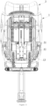
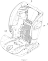
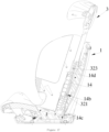
Figure 1 is a cross-sectional view of a child safety seat according to the present disclosure in the first usage state along the front-and-rear direction; -
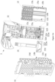
Figure 2 is a partial exploded schematic view ofFigure 1 ; -
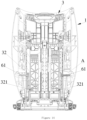
Figure 3 is a partial cross-sectional view of the child safety seat shown inFigure 1 ; -
Figure 4a and 4b are a rear view and a front view of the unlocking member and the position-limit mechanism inFigure 3 , respectively; -
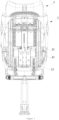
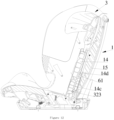
Figure 5 is a cross-sectional view of the child safety seat ofFigure 1 in the second usage state along the front-and-rear direction; -
Figure 6 is a partial exploded schematic view ofFigure 5 ; -
Figure 7 is a partial cross-sectional view of the child safety seat shown inFigure 5 ; -
Figure 8a and 8b are a rear view and a front view of the unlocking member and the position-limit mechanism inFigure 7 , respectively; -
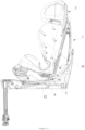
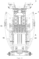
Figure 9 is a schematic structural diagram of another child safety seat according to the present disclosure; -
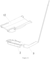
Figure 10a and10b are partial exploded schematic views ofFigure 9 , respectively; -
Figures 11 - 13 are cross-sectional views of the child safety seat ofFigure 9 in the first usage state along the front-and-rear direction; -
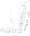
Figure 14 is a cross-sectional view of the child safety seat ofFigure 9 in the first usage state along the left-and-right direction; -
Figure 15 is a partial enlarged view of Part A inFigure 14 ; -
Figures 16 and17 are cross-sectional views of the child safety seat ofFigure 9 in the second usage state along the front-and-rear direction; -
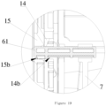
Figure 18 is a cross-sectional view of the child safety seat ofFigure 9 in the second usage state along the left-and-right direction; -
Figure 19 is a partial enlarged view of Part A inFigure 18 ; - 1 - housing; 11 - storage slot; 12 - storage slot cover; 13 - unlocking member cover; 13a - long slot; 2 - seat belt buckle; 3 - head support assembly; 31 - head support fixed part; 311 - first guide slot; 311a - position-limit face; 312 - second guide slot; 313 - gap; 4 - first lock pin seat; 4a - unlocking slope; 41 - first lock pin; 42 - first elastic element; 5 - unlocking member; 5a - unlocking slope; 51 - third elastic element;
- 14 - outer plate cover; 14a - second position-limit portion; 14b - outer lock slot; 14c - first positioning slot; 14d - second positioning slot; 15 - inner plate cover; 15a - first position-limit portion; 15b - inner lock slot; 15c - third positioning slot; 32 - head support; 321 - inner plate cover lock pin; 322 - second elastic element; 323 - positioning lock pin; 323a - protrusion; 324 - fourth elastic element; 33 - adjustment handle; 331 - adjustment tilted slot; 6 - second lock pin seat; 61 - second lock pin; 7 - unlocking member; 7a - unlocking tilted slot; 71 - third elastic element.
- In the following, the preferable embodiments of the present invention are explained in detail combining with the accompanying drawings so that the advantages and features of the present invention can be easily understood by the skilled persons in the art. The orientational words mentioned in the present disclosure are defined according to the observation angle of the child safety seat by those skilled in the art, for example, "left" and "right" corresponding to the left and right sides of the paper in
Figure 3 respectively. - This embodiment provides a child safety seat according to the present invention which comprises a seat body and a five-point safety belt disposed on the seat body, the five-point safety belt mainly consists of two shoulder safety belts, two waist safety belts, a crotch safety belt and a
seat belt buckle 2 connecting the five safety belts to each other, to restrain and protect the child on the seat body. The child safety seat has two usage states, namely a first usage state shown inFigures 1 and3 and a second usage state shown inFigures 5 and7 . - Referring to
Figures 1 - 8b , the seat body comprises ahousing 1, and thehousing 1 is internally provided with astorage slot 11 used for storing thesafety belt buckle 2. When the child safety seat is in the first usage state, thesafety belt buckle 2 is located outside thestorage slot 11 all the time, that is, the five-point safety belt is normally placed on the seat body to allow the use of the five-point safety belt to restrain the child sitting on the seat body. When the child safety seat is in the second usage state, thesafety belt buckle 2 is located in thestorage slot 11, the five-point safety belt is not allowed to be used, and only the vehicle seat belt can be used. By placing theseat belt buckle 2 in thestorage slot 11 of thehousing 1 and buckling astorage slot cover 12, the five-point safety belt can be effectively prevented from being misused in the second usage state. Wherein, theseat belt buckle 2 can be put into thestorage slot 11 in a state of being connected to the seat belt. - The seat body further comprises a
head support assembly 3 disposed on thehousing 1 in a sliding up and down manner, the height of thehead support assembly 3 is adjustable to have a plurality of positions corresponding to different heights, one of the positions is a predetermined position, thehead support assembly 3 can be adjusted up and down in the position below the predetermined position to adapt to the use of a five-point safety belt for smaller children, and thehead support assembly 3 is adjusted at a position above the predetermined position to adapt to the use of vehicle seat belts for older children. When the child safety seat is in the first usage state, and thehead support assembly 3 is in any position between the lowest position and the predetermined position, theseat belt buckle 2 can be put into thestorage slot 11, and when theseat belt buckle 2 is placed in thestorage slot 11, thehead support assembly 3 is adjusted upward to convert the child safety seat to the second usage state. - The seat body further comprises a position-limit mechanism for preventing the
head support assembly 3 from being higher than the predetermined position and an unlockingmember 5 for releasing the position limit of thehead support assembly 3 and the position-limit mechanism, and the unlockingmember 5 is slidably disposed on thehousing 1 and one end of the unlockingmember 5 is movably disposed in thestorage slot 11. When the child safety seat is in the first usage state, blocked by the position-limit mechanism, thehead support assembly 3 is not higher than the predetermined position, that is, thehead support assembly 3 can only be in the lowest position, the predetermined position or between the lowest position and the predetermined position. When the child safety seat is converted from the first usage state to the second usage state, theseat belt buckle 2 is placed in thestorage slot 11 and presses the one end of the unlockingmember 5 to release the position limit of the position-limit mechanism and thehead support assembly 3, and thehead support assembly 3 is able to be adjusted upward. When the child safety seat is in the second usage state, thehead support assembly 3 is higher than the predetermined position, and the height of thehead support assembly 3 is adjusted between the predetermined position and the highest position. Only after theseat belt buckle 2 is put into thestorage slot 11, thehead support assembly 3 can be released from the position limit and adjusted upward to adapt to the height of the child, avoiding the misuse of the five-point safety belt in the second usage state. - Specifically, as shown in
Figure 1 andFigure 2 , in this embodiment, the unlockingmember 5 is disposed on thehousing 1 in a sliding up and down manner, and a lower end portion of the unlockingmember 5 is movably disposed in thestorage slot 11. When theseat belt buckle 2 is put into thestorage slot 11, the end portion of theseat belt buckle 2 presses the lower end of the unlockingmember 5 and drives the unlockingmember 5 to move downward for a certain distance. Between thehousing 1 and the unlockingmember 5 is provided a thirdelastic element 51 for driving the unlockingmember 5 to move upward, and the thirdelastic element 51 is specifically a compression spring disposed between the unlockingmember 5 and thehousing 1, wherein the lower portion of the unlockingmember 5 is connected with the upper end of the compression spring. - The
head support assembly 3 comprises a head support fixedpart 31, and the head support fixedpart 31 is formed with a position-limit face 311a facing upward thereon. The position-limit mechanism comprises a firstlock pin seat 4 disposed on thehousing 1 in a sliding left and right manner, the firstlock pin seat 4 is provided with afirst lock pin 41 cooperating with the position-limit face 311a, and when thehead support assembly 3 is in the predetermined position, thefirst lock pin 41 pushes against the position-limit face 311a, and blocked by the first lock pin, the head support fixedpart 31 cannot continue to slide upward. That is to say, when the child safety seat is in the first usage state, thefirst lock pin 41 is located directly above the position-limit face 311a or pushes against the position-limit face 311a; when the child safety seat is in the second usage state, thefirst lock pin 41 is located on the left or right side of the position-limit face 311a to disengage from the position-limit face 311a. Specifically as shown inFigures 2 ,4a ,4b ,8a and 8b , the head support fixedpart 31 is opened with afirst guide slot 311 thereon, thefirst guide slot 311 extends along a up-and-down direction, the position-limit face 311a is formed on a lower wall of thefirst guide slot 311, and in addition, a right wall of thefirst guide slot 311 is opened with a gap 313 for thefirst lock pin 41 to go in and out, and a lower end of the gap 313 is preferably level with the position-limit face 311a. When the child safety seat is in the first usage state, thefirst lock pin 41 is slidably inserted in thefirst guide slot 311; when the child safety seat is in the second usage state, thefirst lock pin 41 slides out from the gap 313 and is located outside thefirst guide slot 311. - Further, the head support fixed
part 31 is further opened thereon with asecond guide slot 312 extending the up-and-down direction, thesecond guide slot 312 is in communication with thefirst guide slot 311 via the gap 313, and an upper end of the gap 313 is preferably level with an upper wall of thesecond guide slot 312. When the child safety seat is in the second usage state, thefirst lock pin 41 is slidably inserted in thesecond guide slot 312 or located directly under thesecond guide slot 312. As shown inFigures 4a and 4b , when the child safety seat is in the first usage state, the height adjustment range of thehead support assembly 3 is shown as d1 inFigure 4a , and d1 is equal to the length of thefirst guide slot 311; as shown inFigures 8a and 8b , when the child safety seat is in the second usage state, the height adjustment range of thehead support assembly 3 is shown as d2 inFigure 8a , d2 is greater than the length of thesecond guide slot 312, and the lower end of thesecond guide slot 312 is open, and as thehead support assembly 3 is gradually adjusted upward, thefirst lock pin 41 is disengaged from thesecond guide slot 312 and is located directly under thesecond guide slot 312. It should also be noted that: the position-limit face 311a is formed on the lower wall of thefirst guide slot 311, and is used to prevent the height of thehead support assembly 3 from being adjusted upwards above the predetermined position in the first usage state; the upper wall of the twoguide slots 312 also has a position limiting function, which is used to prevent the height of thehead support assembly 3 from being lower than the predetermined position in the second usage state. - The
housing 1 comprises an unlockingmember cover 13, and the unlockingmember cover 13 is buckled on the rear side and the lower side of the unlockingmember 5. An upper portion of the unlockingmember cover 13 is provided with along slot 13a extending in the left-right direction, and thefirst lock pin 41 is inserted into thelong slot 13a to be slidable left and right. The unlockingmember 5 is in a tight contact with the firstlock pin seat 4 and at least one of the components is provided with an unlocking slope that contacts and cooperates with the other component, and the unlocking slope is gradually tilted upward or downward from left to right. Specifically, in this embodiment, the upper end portion of the unlockingmember 5 has an unlockingslope 5a that gradually tilts downward from right to left, and the firstlock pin seat 4 also has an unlockingslope 4a that gradually tilts downward from right to left, and the two unlockingslopes elastic element 42 is provided between the firstlock pin seat 4 and thehousing 1 to push the firstlock pin seat 4 to move so that thefirst lock pin 41 enters thesecond guide slot 312 from thefirst guide slot 311. Specifically, the firstelastic element 42 is a compression spring sleeved on the end portion of the firstlock pin seat 4, and both ends of the compression spring pushes against the firstlock pin seat 4 and thehousing 1, respectively. When the child safety seat is converted from the first usage state to the second usage state, as theseat belt buckle 2 is placed in thestorage slot 11 and presses the lower end of the unlockingmember 5 to move downward as thesafety belt buckle 2, and the unlockingmember 5 is moved downward, so that the firstelastic element 42 is gradually reset, pushing the firstlock pin seat 4 to move to the right to enter thesecond guide slot 312 through the gap 313, the firstlock pin seat 4 is disengaged from the position-limit face 311a in theguide slot 311, and thehead support assembly 3 can be adjusted upward. When the child safety seat is converted from the second usage state to the first usage state, theseat belt buckle 2 is taken out from thestorage slot 11, the thirdelastic element 51 is reset, pushing the unlockingmember 5 to move upward, and the firstlock pin seat 4 moves to the left under the push of the unlockingslope 5a, thefirst lock pin 41 enters thefirst guide slot 311 through the gap 313, and thehead support assembly 3 is not higher than the predetermined position. - The child safety seat in this embodiment is suitable for children of different weights and different ages. A safety seat suitable for children with 0 - 36 Kg is taken as an example to describe the use process of the child safety seat of the present disclosure. For infants of 0 - 18 Kg, the child safety seat needs to be converted to the first usage state, refer to
Figures 1 - 4 , in this first usage state, theseat belt buckle 2 is normally on the seat body, the five-point safety belt must be used to restrain infants; thefirst lock pin 41 is inserted in thefirst guide slot 311, and thehead support assembly 3 can move upward to the predetermined position at most, that is, the height of thehead support assembly 3 can only in the lowest position, the predetermined position, or between the two, to adapt to the height of the child. For older children of 15 - 36 Kg, the child safety seat needs to be converted to the second usage state, as shown inFigures 5 - 8 , in this second usage state, the child is restrained by the vehicle belt and the five-point safety belt cannot be used, theseat belt buckle 2 must be put into thestorage slot 11, and thestorage slot cover 12 should be buckled to prevent misuse of the five-point safety belt; the lower end of the unlockingmember 5 is pressed by theseat belt buckle 2 and moves down, thefirst locking pin 41 is located at or below thesecond guide slot 312, and the height of thehead support assembly 3 is adjusted to above the predetermined position to adapt to the height of older children. -
Figures 9 - 19 show another child safety seat according to the present invention this embodiment andEmbodiment 1 differs in that the unlockingmember 5 and the position-limit mechanism are different. - Referring to
Figures 9 - 19 , the child safety seat comprises a seat body and a five-point safety belt arranged on the seat body. The child safety seat has two usage states, namely a first usage state shown inFigures 11 - 13 and a second usage state shown inFigures 14 and15 . The seat body comprises ahousing 1, and thehousing 1 is internally provided with astorage slot 11 used for storing thesafety belt buckle 2 of the five-point safety belt. When the child safety seat is in the first usage state, the five-point safety belt is used. When the child safety seat is in the second usage state, thesafety belt buckle 2 is located in thestorage slot 11, the five-point safety belt is not allowed to be used, and only the vehicle seat belt can be used to restrain the child. By placing theseat belt buckle 2 in thestorage slot 11 of thehousing 1 and buckling astorage slot cover 12, the five-point safety belt can be effectively prevented from being misused in the second usage state. - The seat body further comprises a
head support assembly 3 disposed on thehousing 1 in a sliding up and down manner, the height of thehead support assembly 3 is adjustable so as to have a plurality of positions corresponding to different heights, and one of the positions is the predetermined position. When the child safety seat is in the first usage state, theseat belt buckle 2 can be put into thestorage slot 11 only when thehead support assembly 3 is in the predetermined position, and when theseat belt buckle 2 is placed in thestorage slot 11, thehead support assembly 3 is adjusted upward to convert the child safety seat to the second usage state. - The seat body further comprises a position-limit mechanism for preventing the
head support assembly 3 from being higher than the predetermined position and an unlockingmember 7 for releasing the position limit of thehead support assembly 3 and the position-limit mechanism, and the unlockingmember 7 is slidably disposed on thehousing 1 and one end of the unlockingmember 7 is movably disposed in thestorage slot 11. When the child safety seat is in the first usage state, blocked by the position-limit mechanism, thehead support assembly 3 is not higher than the predetermined position, that is, thehead support assembly 3 can only be in the lowest position, the predetermined position or between the lowest position and the predetermined position. When the child safety seat is converted from the first usage state to the second usage state, theseat belt buckle 2 enters thestorage slot 11 and presses the one end of the unlockingmember 7 to release the position limit of the position-limit mechanism and thehead support assembly 3. When the child safety seat is in the second usage state, thehead support assembly 3 is higher than the predetermined position, and the height of thehead support assembly 3 is adjusted between the predetermined position and the highest position. Only after theseat belt buckle 2 is put into thestorage slot 11, thehead support assembly 3 can be released from the position limit and adjusted upward to adapt to the height of the child, avoiding the misuse of the five-point safety belt in the second usage state. In addition, when the child safety seat is in the first usage state, theseat belt buckle 2 is located outside thestorage slot 11 only when thehead support assembly 3 is lower than the predetermined position, and the five-point safety belt is used to restrain the child, and theseat belt buckle 2 can be put into thestorage slot 11 when thehead support assembly 3 is in the predetermined position, thereby allowing theseat belt buckle 2 to be put inside thestorage slot 11 to switch to the second usage state. - Referring to
Figure 10b , in this embodiment, the unlockingmember 7 is disposed on thehousing 1 in a sliding up and down manner, and a lower end portion of the unlockingmember 7 is movably disposed in thestorage slot 11. When theseat belt buckle 2 is put into thestorage slot 11, the end portion of theseat belt buckle 2 presses the lower end of the unlockingmember 7 and drives the unlockingmember 7 to move downward for a certain distance. Between thehousing 1 and the unlockingmember 7 is provided a thirdelastic element 71 for driving the unlockingmember 7 to move upward, and the thirdelastic element 71 is specifically a compression spring disposed between the unlockingmember 7 and thehousing 1, wherein the lower portion of the unlockingmember 7 is connected with the upper end of the compression spring. - Combining with
Figure 10a andFigure 13 , thehousing 1 specifically comprises a fixedouter plate cover 14 and aninner plate cover 15 capable of sliding relative to theouter plate cover 14, the position-limit mechanism comprises a first position-limit portion 15a formed on theinner plate cover 15 and a second position-limit portion 14a formed on theouter plate cover 14, the first position-limit portion 15a is located directly under the second position-limit portion 14a, and when thehead support assembly 3 is in the predetermined position, the first position-limit portion 15a pushes against the second position-limit portion 14a. Specifically, in this embodiment, as shown inFigure 13 , theouter plate cover 14 is surrounded and disposed on the front side of theinner plate cover 15, the first position-limit portion 15a and the second position-limit portion 14a respectively protrudes, and the first position-limit portion 15a is a protrusion portion of theinner plate cover 15 extending forward, and the second position-limit portion 14a is a transverse rib of theouter plate cover 14 extending backward. - The seat body further comprises a
second lock pin 61, thesecond lock pin 61 is disposed on a secondlock pin seat 6, the unlockingmember 7 is in a tight contact with the secondlock pin seat 6 and at least one of the components is provided with an unlocking slope that contacts and cooperates with the other component, and the unlocking slope gradually is tilted upward or downward from left to right. An upper end portion of the unlockingmember 7 is provided with an unlocking tiltedslot 7a, the secondlock pin seat 6 is slidably inserted in the unlocking tiltedslot 7a, and the unlocking slope is formed on a wall of the unlocking tiltedslot 7a. The number of the second lock pin is two and they are disposed at intervals on the left and right, theinner plate cover 15 and theouter plate cover 14 are disposed between the two second lock pins 61, the unlocking tiltedslots 7a on the left and right sides are provided symmetrically and a distance between upper ends of the unlocking tiltedslots 7a on the left and right sides is smaller than that between the lower ends thereof. That is, referring toFigure 10b , the left unlocking tiltedslots 7a gradually tilts upward from left to right, and the right unlockingtilted slots 7a gradually tilts upward from right to left. - The
outer plate cover 14 is provided with an outer locking slot 41b into which thesecond lock pin 61 is inserted, and theinner plate cover 15 is provided with aninner locking slot 15b into which thesecond lock pin 61 is inserted. Thehead support assembly 3 specifically comprises ahead support 32 and an inner platecover lock pin 321 that can be inserted into theinner lock slot 15b, in this embodiment, the lower portion of thehead support 32 is located between theinner plate cover 15 and theouter plate cover 14. Combining withFigures 14 and15 , when the child safety seat is in the first usage state, the inner platecover lock pin 321 is inserted into theinner lock slot 15b to connect thehead support assembly 3 and theinner plate cover 15 as a whole, thereby synchronously sliding up and down with respect to theouter plate cover 14, at this moment, when thehead support assembly 3 slides to the predetermined position as shown inFigure 13 , the second position-limit portion 14a on the outer plate cover 14 blocks the first limitingportion 15a on theinner plate cover 15, and thehead support assembly 3 cannot be further adjusted upward. As shown inFigures 18 and19 , when the child safety seat is in the second usage state, theinner lock slot 15b and theouter lock slot 14b are aligned with each other, and thesecond lock pin 61 is inserted into theinner lock slot 15b and theouter lock slot 14b, so that theinner plate cover 15 and theouter plate cover 14 are connected as a whole, and at this time, thesecond lock pin 61 pushes the inner platecover lock pin 321 out of theinner lock slot 15b, so that thehead support assembly 3 is disengaged from theinner plate cover 15, so as to be able to slide up and down with respective to theinner plate cover 15 and theouter plate cover 14. After theseat belt buckle 2 is placed in thestorage slot 11, thesecond lock pin 61 moves in the unlocking tiltedslot 7a, and the inner platecover lock pin 321 is pushed from theinner lock slot 15b. - The lower portion of the
head support 32 is provided with a first mounting slot extending in the left-right direction, the inner platecover lock pin 321 is slidably disposed in the first mounting slot, between the wall of the first mounting slot and the inner platecover lock pin 321 is disposed a secondelastic element 322 for inserting the inner platecover lock pin 321 into theinner lock slot 15b. The secondelastic element 322 is specifically a compression spring disposed on the wall of the mounting slot and the inner platecover lock pin 321. When the child safety seat is in the first usage state, the secondelastic element 322 is in an initial state; when it is converted to the second usage state, the secondelastic element 322 is compressed by the inner platecover lock pin 321 pushed out of theinner lock slot 15b; when thesecond lock pin 61 is disengaged from theinner lock slot 15b, the secondelastic element 322 is reset and pushes the inner platecover lock pin 321 into theinner lock slot 15b to connect thehead support 32 and theinner plate cover 15. - The lower part of the
head support 32 is also provided with a second mounting slot extending in the left and right direction, two positioning lock pins 323 are provided in the second mounting slot, thepositioning lock pin 323 is able to slide left and right in the second mounting slot, and thepositioning lock pin 323 is located below the inner platecover lock pin 321. The portion of theouter plate cover 14 below theouter lock slot 14b is provided with a plurality offirst positioning slots 14c at equal intervals up and down, and the part of theouter plate cover 14 above theouter lock slot 14b is provided with a plurality ofsecond positioning slots 14d at equal intervals up and down, the portion of theinner plate cover 15 above theinner lock slot 15b is provided with a plurality ofthird positioning slots 15c at equal intervals up and down, and thesecond positioning slots 14d and thethird positioning slots 15c have the same number and correspond one to one. When the child safety seat is in the first usage state, thepositioning lock pin 323 is inserted into any of thefirst positioning slots 14c to lock thehead support 32 at a specified height; in this embodiment, the number of thefirst positioning slots 14c is six, thehead support assembly 3 can be adjusted in six positions comprising the predetermined position when in the first usage state. When the child safety seat is in the second usage state, eachsecond positioning slot 14d is aligned with the correspondingthird positioning slot 15c, thepositioning lock pin 323 is inserted into anysecond positioning slot 14d and the correspondingthrid positioning slot 15c, and thehead support 32 is locked at a specified height; in this embodiment, the number of thesecond positioning slots 14d and thethird positioning slots 15c are five, respectively, and thehead support assembly 3 can be adjusted in five positions in the first usage state. - The
head support assembly 3 also comprises anadjustment handle 33 that can slide up and down, the lower part of the adjustment handle 33 is provided with a pair of adjustment tiltedslots 331, the pair of adjustment tiltedslots 331 are disposed symmetrically to the left and right, and the distance between the upper ends of the two is smaller than that between the lower ends. Thepositioning lock pin 323 has aprotrusion 323a slidably inserted in the adjustment tiltedslot 331. Pull up theadjustment handle 33, theprotrusion 323a enters the lower end portion of the adjustment tiltedslot 331, and under the action of the wall of the adjustment tiltedslot 331, thepositioning lock pin 323 retracts into the second mounting slot, thereby disengaging from thefirst positioning slot 14c or thesecond positioning slot 14d and thethird positioning slot 15c, realizing the unlocking of thehead support 32, and thehead support 32 can be adjusted up and down. A fourthelastic element 324 for inserting thepositioning lock pin 323 into thefirst positioning slot 14c or into thesecond positioning slot 14d and thethird positioning slot 15c is provided between thepositioning lock pin 323 and the wall of the second mounting slot, and the fourthelastic element 324 is specifically a compression spring disposed on the wall of the second mounting slot and thepositioning lock pin 323. - A safety seat suitable for children with 0 - 36 Kg is taken as an example to describe the use process of the child safety seat of the present disclosure. For infants of 0 - 18 Kg, the child safety seat needs to be converted to the first usage state, the
seat belt buckle 2 is normally on the seat body, and the five-point safety belt is used to restrain infants, as shown inFigures 11 - 17 . InFigures 11 and12 , thehead support assembly 3 is in the lowest position, and thepositioning lock pin 323 is inserted in the lowestfirst positioning slot 14c; inFigure 13 , thehead support assembly 3 is in the predetermined position, and thepositioning lock pin 323 is inserted into the uppermostfirst positioning slot 14c. As shown inFigures 14 and15 , in the first usage state, thesecond lock pin 61 is only inserted in theouter lock slot 14b, the inner platecover lock pin 321 is inserted in theinner lock slot 15b, and theinner plate cover 15 moves along with thehead support assembly 3, and thehead support assembly 3 can move up to the predetermined position at most, that is, the height of thehead support assembly 3 can only be at the lowest position shown inFigures 11 and12 , the predetermined position shown inFigure 13 , or between the two. For older children of 15 - 36 Kg, the child safety seat needs to be converted to the second usage state, as shown inFigures 16 - 17 , in the second usage state, the child is restrained by the vehicle belt and the five-point safety belt cannot be used, theseat belt buckle 2 must be put into thestorage slot 11, and thestorage slot cover 12 should be buckled to prevent misuse of the five-point safety belt; the lower end portion of the unlockingmember 7 is pressed by theseat belt buckle 2 and moves downward, thesecond lock pin 61 is inserted into theinner lock slot 15b and theouter lock slot 14b to connect theinner plate cover 15 and the outer plate cover 14 (as shown inFigures 18 and19 ), the inner platecover lock pin 321 is disengaged from theinner lock slot 15b so that thehead support assembly 3 moves relative to theinner plate cover 15 and theouter plate cover 14, and the height of thehead support assembly 3 is adjusted to above the predetermined position. - The embodiments described above are only for illustrating the technical concepts and features of the present invention are preferred implementations, and are intended to make those skilled in the art being able to understand the present invention and thereby implement it, and should not be concluded to limit the protective scope of this invention.
Claims (15)
- A child safety seat, comprising a seat body and a five-point safety belt disposed on the seat body, the seat body comprising a housing (1), the five-point safety belt comprising a safety belt buckle, the housing (1) being internally provided with a storage slot (11) used for storing the safety belt buckle; is characterized in that,
the seat body further comprises a head support assembly (3) disposed on the housing (1) in a sliding up and down manner, the head support assembly (3) has a predetermined position, and when the safety belt buckle is placed in the storage slot (11), the head support assembly (3) is allowed to be higher than the predetermined position. - The child safety seat according to claim 1, is characterized in that, the child safety seat has a first usage state and a second usage state,in the first usage state, the head support assembly (3) is not higher than the predetermined position, and the safety belt buckle is located outside the storage slot (11) all the time to allow the use of the five-point safety belt; or, the safety belt buckle is located outside the storage slot (11) only when the head support assembly (3) is lower than the predetermined position, and the safety belt buckle is able to be put into the storage slot (11) when the head support assembly (3) is located in the predetermined position;in the second usage state, the safety belt buckle is located in the storage slot (11), and the head support assembly (3) is higher than the predetermined position.
- The child safety seat according to claim 2, is characterized in that, the seat body further comprises a position-limit mechanism for preventing the head support assembly (3) from being higher than the predetermined position and an unlocking member (5) for releasing the position limit of the head support assembly (3) and the position-limit mechanism, and the unlocking member (5) is slidably disposed on the housing (1) and one end of the unlocking member (5) is movably disposed in the storage slot (11); when the child safety seat is converted from the first usage state to the second usage state, the seat belt buckle (2) enters the storage slot (11) and presses the one end of the unlocking member (5) to release the position limit of the head support assembly (3) and the position-limit mechanism.
- The child safety seat according to claim 3, is characterized in that, the unlocking member (5) is disposed on the housing (1) in a sliding up and down manner, and a lower end portion of the unlocking member (5) is movably disposed in the storage slot (11).
- The child safety seat according to claim 4, is characterized in that, the head support assembly (3) comprises a head support fixed part (31), and the head support fixed part (31) is formed with a position-limit face (311a) facing upward thereon;the position-limit mechanism comprises a first lock pin seat (4) disposed on the housing (1) in a sliding left and right manner, the first lock pin seat (4) is provided with a first lock pin (41) cooperating with the position-limit face (311a), and the head support assembly (3) is in the predetermined position when the first lock pin (41) pushes against the position-limit face (311a);the unlocking member (5) is in a tight contact with the first lock pin seat (4) and at least one of the components is provided with an unlocking slope (4a , 5a) that contacts and cooperates with the other component, and the unlocking slope (4a , 5a) gradually is tilted upward or downward from left to right;when the child safety seat is in the first usage state, the first lock pin (41) is located directly above the position-limit face (311a) or pushes against the position-limit face (311a); when the child safety seat is in the second usage state, the first lock pin (41) is located on the left or right side of the position-limit face (311a) to disengage from the position-limit face (311a).
- The child safety seat according to claim 5, is characterized in that, the head support fixed part (31) is opened with a first guide slot (311) thereon, the first guide slot (311) extends along a up-and-down direction, the position-limit face (311a) is formed on a lower wall of the first guide slot (311), and a left or right wall of the first guide slot (311) is opened with a gap (313) for the first lock pin (41) to go in and out; when the child safety seat is in the first usage state, the first lock pin (41) is slidably inserted in the first guide slot (311); when the child safety seat is in the second usage state, the first lock pin (41) is located outside the first guide slot (311).
- The child safety seat according to claim 6, is characterized in that, the head support fixed part (31) is further opened with a second guide slot (312) thereon, the second guide slot (312) is in communication with the first guide slot (311) via the gap (313); when the child safety seat is in the second usage state, the first lock pin (41) is slidably inserted in the second guide slot (312) or located directly under the second guide slot (312).
- The child safety seat according to claim 5, is characterized in that, the position-limit mechanism further comprises a first elastic element (42) disposed between the housing (1) and the first lock pin seat (4).
- The child safety seat according to claim 4, is characterized in that, the housing (1) comprises an outer plate cover (14) and an inner plate cover (15) capable of sliding relative to the outer plate cover (14), the position-limit mechanism comprises a first position-limit portion (15a) formed on the inner plate cover (15) and a second position-limit portion (14a) formed on the outer plate cover (14), the first position-limit portion (15a) is located directly under the second position-limit portion (14a), and when the head support assembly (3) is in the predetermined position, the first position-limit portion (15a) pushes against the second position-limit portion (14a);the seat body further comprises a second lock pin (61), the second lock pin (61) is disposed on a second lock pin seat (6), the unlocking member (7) is in a tight contact with the second lock pin seat (6) and at least one of the components is provided with an unlocking slope that contacts and cooperates with the other component, and the unlocking slope gradually is tilted upward or downward from left to right;the outer plate cover (14) is provided with an outer locking slot into which the second lock pin (61) is inserted, and the inner plate cover (15) is provided with an inner locking slot into which the second lock pin (61) is inserted;the head support assembly (3) comprises a head support (32) and an inner plate cover (15) lock pin capable of inserting into the inner locking slot;when the child safety seat is in the first usage state, the inner plate cover (15) lock pin is inserted into the inner locking slot, the head support assembly (3) and the inner plate cover (15) are connected to slide with respect to the outer plate cover (14) synchronously; when the child safety seat is in the second usage state, the second lock pin (61) is inserted into the inner locking slot and the outer locking slot, so that the inner plate cover (15) and the outer plater cover are connected and the inner plate cover (15) lock pin is pushed out of the inner locking slot, and the head support assembly (3) is disengaged from the inner plate cover (15) so as to slide up and down with respect to the inner plate cover (15) and the outer plate cover (14) .
- The child safety seat according to claim 9, is characterized in that, an upper end portion of the unlocking member (7) is provided with an unlocking tilted slot (7a), the second lock pin seat (6) is slidably inserted in the unlocking tilted slot (7a), and the unlocking slope is formed on a wall of the unlocking tilted slot (7a).
- The child safety seat according to claim 10, is characterized in that, the number of the second lock pin (61) is two and they are disposed at intervals on the left and right, the inner plate cover (15) and the outer plate cover (14) are disposed between the two second lock pins (61), and a distance between upper ends of the unlocking tilted slots (7a) on the left and right sides is smaller than that between the lower ends thereof.
- The child safety seat according to claim 9, is characterized in that, the head support (32) is provided with a first mounting slot, the inner plate cover lock pin (321) is slidably disposed in the first mounting slot, and a wall of the first mounting slot and the inner plate cover (15) is provided with a second elastic element (322) therebetween for inserting the inner plate cover lock pin (321) into the inner lock slot (15b).
- The child safety seat according to claim 9, is characterized in that, the first position-limit portion (15a) and the second position-limit portion (14a) are respectively protrusions (323a).
- The child safety seat according to claim 9, is characterized in that, a second mounting slot is provided on the head support (32), the second mounting slot is provided therein with a positioning lock pin (323) capable of sliding left and right, a lower portion of the outer plate cover (14) is provided with a plurality of first positioning slots (14c) spaced up and down, an upper portion of the outer plate cover (14) is provided with a plurality of second positioning slots (14d) spaced up and down, the inner plate cover (15) is provided with a plurality of third positioning slots (15c) spaced up and down, and the second positioning slots (14d) and the third positioning slots (15c) correspond one to one; when the child safety seat is in the first usage state, the positioning lock pin (323) is inserted into any of the first positioning slots (14c); when the child safety seat is in the second usage state, the second positioning slots (14d) are aligned with the corresponding third positioning slots (15c), and the positioning lock pin (323) is inserted into any of the second positioning slots (14d) and the corresponding third positioning slot (15c),
preferably, the head support assembly (3) further comprises an adjustment handle (33) capable of sliding up and down, a lower portion of the adjustment handle (33) is provided with an adjustment tilted slot (331), and the positioning lock pin (323) is provided with a protrusion (323a) slidably inserted in the adjustment tilted slot (331). - The child safety seat according to any one of claims 4 - 14, is characterized in that,
between the housing (1) and the unlocking member (5) is provided a third elastic element (51, 71) for driving the unlocking member (5,7) to move upward.
Applications Claiming Priority (2)
| Application Number | Priority Date | Filing Date | Title |
|---|---|---|---|
| CN201811024985.6A CN109017474B (en) | 2018-09-04 | 2018-09-04 | A child safety seat |
| PCT/CN2018/119769 WO2020048032A1 (en) | 2018-09-04 | 2018-12-07 | Child safety seat |
Publications (4)
| Publication Number | Publication Date |
|---|---|
| EP3848239A1 EP3848239A1 (en) | 2021-07-14 |
| EP3848239A4 EP3848239A4 (en) | 2022-06-08 |
| EP3848239B1 true EP3848239B1 (en) | 2025-03-26 |
| EP3848239C0 EP3848239C0 (en) | 2025-03-26 |
Family
ID=64623226
Family Applications (1)
| Application Number | Title | Priority Date | Filing Date |
|---|---|---|---|
| EP18932840.4A Active EP3848239B1 (en) | 2018-09-04 | 2018-12-07 | Child safety seat |
Country Status (5)
| Country | Link |
|---|---|
| US (1) | US11413992B2 (en) |
| EP (1) | EP3848239B1 (en) |
| JP (1) | JP7111890B2 (en) |
| CN (1) | CN109017474B (en) |
| WO (1) | WO2020048032A1 (en) |
Families Citing this family (3)
| Publication number | Priority date | Publication date | Assignee | Title |
|---|---|---|---|---|
| CN117962713A (en) * | 2020-10-13 | 2024-05-03 | 宝钜瑞士股份有限公司 | How to adjust the headrest height |
| CN115366759B (en) * | 2021-05-21 | 2025-03-18 | 明门瑞士股份有限公司 | Child safety seats and support components |
| WO2025141644A1 (en) * | 2023-12-25 | 2025-07-03 | コンビ株式会社 | Child car seat |
Family Cites Families (22)
| Publication number | Priority date | Publication date | Assignee | Title |
|---|---|---|---|---|
| US6491348B1 (en) * | 2000-07-31 | 2002-12-10 | Cosco Management, Inc. | Child vehicle seat with child-restraint harness adjustment mechanism |
| JP2004359193A (en) * | 2003-06-09 | 2004-12-24 | Aprica Kassai Inc | Detachable child seat |
| ES1061044Y (en) * | 2005-09-12 | 2006-04-01 | Jane Sa | CHILD SEAT FOR CARS. |
| CN201176134Y (en) * | 2008-03-14 | 2009-01-07 | 林锡雷 | Child's safety seat for vehicle capable of interlock regulating |
| WO2010088317A1 (en) * | 2009-01-27 | 2010-08-05 | Graco Children's Products Inc. | Child safety seat harness tensioning device |
| NL1036865C2 (en) * | 2009-04-16 | 2010-10-19 | Maxi Miliaan Bv | Child vehicle seat. |
| DE102009017601B4 (en) * | 2009-04-16 | 2011-06-22 | RECARO GmbH & Co. KG, 73230 | Child car seat |
| EP2913222B1 (en) * | 2014-02-28 | 2020-01-22 | Britax Römer Kindersicherheit GmbH | Child safety seat |
| DE102015109108A1 (en) * | 2015-06-09 | 2016-12-15 | Recaro Child Safety Gmbh & Co. Kg | Child seat device |
| US10124702B2 (en) * | 2015-10-30 | 2018-11-13 | Dorel Juvenile Group, Inc. | Child restraint with belt management system |
| CN105857131B (en) * | 2016-06-18 | 2018-05-29 | 宁波市博林日用品制造有限公司 | A kind of automobile children safety chair |
| CN206426885U (en) * | 2016-06-23 | 2017-08-22 | 瑞典雄霸安全制品有限公司 | Band system with locking mechanism |
| CN106143226B (en) * | 2016-08-29 | 2018-12-21 | 好孩子儿童用品有限公司 | A kind of child safety seat |
| CN106314221B (en) * | 2016-08-29 | 2018-07-10 | 好孩子儿童用品有限公司 | A kind of child safety seat |
| US10266077B2 (en) * | 2016-11-11 | 2019-04-23 | Wonderland Switzerland Ag | Child safety seat |
| US10507743B2 (en) * | 2017-02-09 | 2019-12-17 | Dorel Juvenile Group, Inc. | Juvenile vehicle seat with adjustable headrest |
| CN107527917B (en) * | 2017-08-31 | 2019-12-10 | 上海华虹宏力半导体制造有限公司 | 1.5T depletion type SONOS non-volatile memory and manufacturing method thereof |
| CN107627916A (en) * | 2017-09-01 | 2018-01-26 | 浙江乐优贝汽车用品有限公司 | Children's seat |
| EP3590757B1 (en) * | 2017-09-06 | 2021-04-21 | BRITAX RÖMER Kindersicherheit GmbH | Child safety seat with headrest height adjustment mechanism |
| CN107627917B (en) | 2017-10-11 | 2024-03-19 | 宁波惠尔顿婴童安全科技股份有限公司 | Child safety seat buckle and safety belt storage structure |
| US10730414B2 (en) * | 2017-12-11 | 2020-08-04 | Evenflo Company, Inc. | Adjustable headrest for child car seat |
| CN209208542U (en) * | 2018-09-04 | 2019-08-06 | 好孩子儿童用品有限公司 | A kind of child safety seat |
-
2018
- 2018-09-04 CN CN201811024985.6A patent/CN109017474B/en active Active
- 2018-12-07 WO PCT/CN2018/119769 patent/WO2020048032A1/en not_active Ceased
- 2018-12-07 EP EP18932840.4A patent/EP3848239B1/en active Active
- 2018-12-07 JP JP2021512547A patent/JP7111890B2/en active Active
- 2018-12-07 US US17/273,145 patent/US11413992B2/en active Active
Also Published As
| Publication number | Publication date |
|---|---|
| US20210323450A1 (en) | 2021-10-21 |
| JP2021535861A (en) | 2021-12-23 |
| CN109017474B (en) | 2023-05-23 |
| EP3848239A1 (en) | 2021-07-14 |
| EP3848239A4 (en) | 2022-06-08 |
| EP3848239C0 (en) | 2025-03-26 |
| US11413992B2 (en) | 2022-08-16 |
| WO2020048032A1 (en) | 2020-03-12 |
| JP7111890B2 (en) | 2022-08-02 |
| CN109017474A (en) | 2018-12-18 |
Similar Documents
| Publication | Publication Date | Title |
|---|---|---|
| CA2763992C (en) | Child safety seat assembly | |
| US4376551A (en) | Child care seat and restraining system | |
| EP3848239B1 (en) | Child safety seat | |
| EP1904335B1 (en) | Child safety seat | |
| CN102371920B (en) | Combination structure of baby safety seat | |
| KR20190027340A (en) | Child safety seat with headrest hight adjustment mechanism | |
| CA2010641C (en) | Vehicle seat for a child | |
| US4909574A (en) | Child's car seat restraint system | |
| CN107618406B (en) | child safety seat | |
| CA3124462A1 (en) | Child restraint carrier and locking mechanism thereof | |
| US5690382A (en) | Adjustable child-restraint shield | |
| KR200438960Y1 (en) | Car seat | |
| US20220219580A1 (en) | Adjustable protector and safety seat | |
| EP0155784A2 (en) | Vehicle seating equipment for children | |
| KR20180099688A (en) | A child seat for attachment to a vehicle seat | |
| US7448690B2 (en) | Child safety seat with emergency harness release | |
| US20260027954A1 (en) | Child carrier | |
| CN209208542U (en) | A kind of child safety seat | |
| CN107599905B (en) | Headrest adjusting mechanism of child safety seat | |
| CN218929265U (en) | Pull-up belt assembly for automobile child safety seat and child safety seat | |
| CN215904358U (en) | child car seat | |
| WO2020168131A1 (en) | Universal child seat base for isofix installation | |
| CN216184663U (en) | Split type headrest subassembly and children's safety seat | |
| KR200438961Y1 (en) | Car seat | |
| US20090134678A1 (en) | Child safety seat with emergency harness release |
Legal Events
| Date | Code | Title | Description |
|---|---|---|---|
| STAA | Information on the status of an ep patent application or granted ep patent |
Free format text: STATUS: THE INTERNATIONAL PUBLICATION HAS BEEN MADE |
|
| PUAI | Public reference made under article 153(3) epc to a published international application that has entered the european phase |
Free format text: ORIGINAL CODE: 0009012 |
|
| STAA | Information on the status of an ep patent application or granted ep patent |
Free format text: STATUS: REQUEST FOR EXAMINATION WAS MADE |
|
| 17P | Request for examination filed |
Effective date: 20210303 |
|
| AK | Designated contracting states |
Kind code of ref document: A1 Designated state(s): AL AT BE BG CH CY CZ DE DK EE ES FI FR GB GR HR HU IE IS IT LI LT LU LV MC MK MT NL NO PL PT RO RS SE SI SK SM TR |
|
| DAV | Request for validation of the european patent (deleted) | ||
| DAX | Request for extension of the european patent (deleted) | ||
| A4 | Supplementary search report drawn up and despatched |
Effective date: 20220509 |
|
| RIC1 | Information provided on ipc code assigned before grant |
Ipc: B60N 2/28 20060101AFI20220502BHEP |
|
| GRAP | Despatch of communication of intention to grant a patent |
Free format text: ORIGINAL CODE: EPIDOSNIGR1 |
|
| STAA | Information on the status of an ep patent application or granted ep patent |
Free format text: STATUS: GRANT OF PATENT IS INTENDED |
|
| INTG | Intention to grant announced |
Effective date: 20241119 |
|
| GRAS | Grant fee paid |
Free format text: ORIGINAL CODE: EPIDOSNIGR3 |
|
| GRAA | (expected) grant |
Free format text: ORIGINAL CODE: 0009210 |
|
| STAA | Information on the status of an ep patent application or granted ep patent |
Free format text: STATUS: THE PATENT HAS BEEN GRANTED |
|
| AK | Designated contracting states |
Kind code of ref document: B1 Designated state(s): AL AT BE BG CH CY CZ DE DK EE ES FI FR GB GR HR HU IE IS IT LI LT LU LV MC MK MT NL NO PL PT RO RS SE SI SK SM TR |
|
| REG | Reference to a national code |
Ref country code: GB Ref legal event code: FG4D |
|
| REG | Reference to a national code |
Ref country code: CH Ref legal event code: EP |
|
| REG | Reference to a national code |
Ref country code: DE Ref legal event code: R096 Ref document number: 602018080606 Country of ref document: DE |
|
| REG | Reference to a national code |
Ref country code: IE Ref legal event code: FG4D |
|
| U01 | Request for unitary effect filed |
Effective date: 20250424 |
|
| U07 | Unitary effect registered |
Designated state(s): AT BE BG DE DK EE FI FR IT LT LU LV MT NL PT RO SE SI Effective date: 20250502 |
|
| PG25 | Lapsed in a contracting state [announced via postgrant information from national office to epo] |
Ref country code: RS Free format text: LAPSE BECAUSE OF FAILURE TO SUBMIT A TRANSLATION OF THE DESCRIPTION OR TO PAY THE FEE WITHIN THE PRESCRIBED TIME-LIMIT Effective date: 20250626 |
|
| PG25 | Lapsed in a contracting state [announced via postgrant information from national office to epo] |
Ref country code: NO Free format text: LAPSE BECAUSE OF FAILURE TO SUBMIT A TRANSLATION OF THE DESCRIPTION OR TO PAY THE FEE WITHIN THE PRESCRIBED TIME-LIMIT Effective date: 20250626 |
|
| PG25 | Lapsed in a contracting state [announced via postgrant information from national office to epo] |
Ref country code: HR Free format text: LAPSE BECAUSE OF FAILURE TO SUBMIT A TRANSLATION OF THE DESCRIPTION OR TO PAY THE FEE WITHIN THE PRESCRIBED TIME-LIMIT Effective date: 20250326 |
|
| PG25 | Lapsed in a contracting state [announced via postgrant information from national office to epo] |
Ref country code: GR Free format text: LAPSE BECAUSE OF FAILURE TO SUBMIT A TRANSLATION OF THE DESCRIPTION OR TO PAY THE FEE WITHIN THE PRESCRIBED TIME-LIMIT Effective date: 20250627 |
|
| PG25 | Lapsed in a contracting state [announced via postgrant information from national office to epo] |
Ref country code: SM Free format text: LAPSE BECAUSE OF FAILURE TO SUBMIT A TRANSLATION OF THE DESCRIPTION OR TO PAY THE FEE WITHIN THE PRESCRIBED TIME-LIMIT Effective date: 20250326 |
|
| PG25 | Lapsed in a contracting state [announced via postgrant information from national office to epo] |
Ref country code: ES Free format text: LAPSE BECAUSE OF FAILURE TO SUBMIT A TRANSLATION OF THE DESCRIPTION OR TO PAY THE FEE WITHIN THE PRESCRIBED TIME-LIMIT Effective date: 20250326 |
|
| PG25 | Lapsed in a contracting state [announced via postgrant information from national office to epo] |
Ref country code: PL Free format text: LAPSE BECAUSE OF FAILURE TO SUBMIT A TRANSLATION OF THE DESCRIPTION OR TO PAY THE FEE WITHIN THE PRESCRIBED TIME-LIMIT Effective date: 20250326 |
|
| PG25 | Lapsed in a contracting state [announced via postgrant information from national office to epo] |
Ref country code: SK Free format text: LAPSE BECAUSE OF FAILURE TO SUBMIT A TRANSLATION OF THE DESCRIPTION OR TO PAY THE FEE WITHIN THE PRESCRIBED TIME-LIMIT Effective date: 20250326 |
|
| PG25 | Lapsed in a contracting state [announced via postgrant information from national office to epo] |
Ref country code: IS Free format text: LAPSE BECAUSE OF FAILURE TO SUBMIT A TRANSLATION OF THE DESCRIPTION OR TO PAY THE FEE WITHIN THE PRESCRIBED TIME-LIMIT Effective date: 20250726 |
|
| U20 | Renewal fee for the european patent with unitary effect paid |
Year of fee payment: 8 Effective date: 20251209 |
|
| PG25 | Lapsed in a contracting state [announced via postgrant information from national office to epo] |
Ref country code: CZ Free format text: LAPSE BECAUSE OF FAILURE TO SUBMIT A TRANSLATION OF THE DESCRIPTION OR TO PAY THE FEE WITHIN THE PRESCRIBED TIME-LIMIT Effective date: 20250326 |
|
| PLBE | No opposition filed within time limit |
Free format text: ORIGINAL CODE: 0009261 |
|
| STAA | Information on the status of an ep patent application or granted ep patent |
Free format text: STATUS: NO OPPOSITION FILED WITHIN TIME LIMIT |
|
| REG | Reference to a national code |
Ref country code: CH Ref legal event code: L10 Free format text: ST27 STATUS EVENT CODE: U-0-0-L10-L00 (AS PROVIDED BY THE NATIONAL OFFICE) Effective date: 20260211 |
|
| 26N | No opposition filed |
Effective date: 20260105 |