EP3848217A1 - Display device for vehicle - Google Patents
Display device for vehicle Download PDFInfo
- Publication number
- EP3848217A1 EP3848217A1 EP20164227.9A EP20164227A EP3848217A1 EP 3848217 A1 EP3848217 A1 EP 3848217A1 EP 20164227 A EP20164227 A EP 20164227A EP 3848217 A1 EP3848217 A1 EP 3848217A1
- Authority
- EP
- European Patent Office
- Prior art keywords
- roller
- display device
- frame
- flexible display
- vehicle
- Prior art date
- Legal status (The legal status is an assumption and is not a legal conclusion. Google has not performed a legal analysis and makes no representation as to the accuracy of the status listed.)
- Granted
Links
Images


Classifications
-
- G—PHYSICS
- G09—EDUCATION; CRYPTOGRAPHY; DISPLAY; ADVERTISING; SEALS
- G09F—DISPLAYING; ADVERTISING; SIGNS; LABELS OR NAME-PLATES; SEALS
- G09F9/00—Indicating arrangements for variable information in which the information is built-up on a support by selection or combination of individual elements
- G09F9/30—Indicating arrangements for variable information in which the information is built-up on a support by selection or combination of individual elements in which the desired character or characters are formed by combining individual elements
- G09F9/301—Indicating arrangements for variable information in which the information is built-up on a support by selection or combination of individual elements in which the desired character or characters are formed by combining individual elements flexible foldable or roll-able electronic displays, e.g. thin LCD, OLED
-
- B—PERFORMING OPERATIONS; TRANSPORTING
- B60—VEHICLES IN GENERAL
- B60K—ARRANGEMENT OR MOUNTING OF PROPULSION UNITS OR OF TRANSMISSIONS IN VEHICLES; ARRANGEMENT OR MOUNTING OF PLURAL DIVERSE PRIME-MOVERS IN VEHICLES; AUXILIARY DRIVES FOR VEHICLES; INSTRUMENTATION OR DASHBOARDS FOR VEHICLES; ARRANGEMENTS IN CONNECTION WITH COOLING, AIR INTAKE, GAS EXHAUST OR FUEL SUPPLY OF PROPULSION UNITS IN VEHICLES
- B60K35/00—Instruments specially adapted for vehicles; Arrangement of instruments in or on vehicles
-
- B—PERFORMING OPERATIONS; TRANSPORTING
- B60—VEHICLES IN GENERAL
- B60Q—ARRANGEMENT OF SIGNALLING OR LIGHTING DEVICES, THE MOUNTING OR SUPPORTING THEREOF OR CIRCUITS THEREFOR, FOR VEHICLES IN GENERAL
- B60Q9/00—Arrangement or adaptation of signal devices not provided for in one of main groups B60Q1/00 - B60Q7/00, e.g. haptic signalling
-
- B—PERFORMING OPERATIONS; TRANSPORTING
- B60—VEHICLES IN GENERAL
- B60K—ARRANGEMENT OR MOUNTING OF PROPULSION UNITS OR OF TRANSMISSIONS IN VEHICLES; ARRANGEMENT OR MOUNTING OF PLURAL DIVERSE PRIME-MOVERS IN VEHICLES; AUXILIARY DRIVES FOR VEHICLES; INSTRUMENTATION OR DASHBOARDS FOR VEHICLES; ARRANGEMENTS IN CONNECTION WITH COOLING, AIR INTAKE, GAS EXHAUST OR FUEL SUPPLY OF PROPULSION UNITS IN VEHICLES
- B60K35/00—Instruments specially adapted for vehicles; Arrangement of instruments in or on vehicles
- B60K35/10—Input arrangements, i.e. from user to vehicle, associated with vehicle functions or specially adapted therefor
-
- B—PERFORMING OPERATIONS; TRANSPORTING
- B60—VEHICLES IN GENERAL
- B60K—ARRANGEMENT OR MOUNTING OF PROPULSION UNITS OR OF TRANSMISSIONS IN VEHICLES; ARRANGEMENT OR MOUNTING OF PLURAL DIVERSE PRIME-MOVERS IN VEHICLES; AUXILIARY DRIVES FOR VEHICLES; INSTRUMENTATION OR DASHBOARDS FOR VEHICLES; ARRANGEMENTS IN CONNECTION WITH COOLING, AIR INTAKE, GAS EXHAUST OR FUEL SUPPLY OF PROPULSION UNITS IN VEHICLES
- B60K35/00—Instruments specially adapted for vehicles; Arrangement of instruments in or on vehicles
- B60K35/20—Output arrangements, i.e. from vehicle to user, associated with vehicle functions or specially adapted therefor
- B60K35/21—Output arrangements, i.e. from vehicle to user, associated with vehicle functions or specially adapted therefor using visual output, e.g. blinking lights or matrix displays
- B60K35/22—Display screens
- B60K35/223—Flexible displays
-
- B—PERFORMING OPERATIONS; TRANSPORTING
- B60—VEHICLES IN GENERAL
- B60K—ARRANGEMENT OR MOUNTING OF PROPULSION UNITS OR OF TRANSMISSIONS IN VEHICLES; ARRANGEMENT OR MOUNTING OF PLURAL DIVERSE PRIME-MOVERS IN VEHICLES; AUXILIARY DRIVES FOR VEHICLES; INSTRUMENTATION OR DASHBOARDS FOR VEHICLES; ARRANGEMENTS IN CONNECTION WITH COOLING, AIR INTAKE, GAS EXHAUST OR FUEL SUPPLY OF PROPULSION UNITS IN VEHICLES
- B60K35/00—Instruments specially adapted for vehicles; Arrangement of instruments in or on vehicles
- B60K35/20—Output arrangements, i.e. from vehicle to user, associated with vehicle functions or specially adapted therefor
- B60K35/25—Output arrangements, i.e. from vehicle to user, associated with vehicle functions or specially adapted therefor using haptic output
-
- B—PERFORMING OPERATIONS; TRANSPORTING
- B60—VEHICLES IN GENERAL
- B60K—ARRANGEMENT OR MOUNTING OF PROPULSION UNITS OR OF TRANSMISSIONS IN VEHICLES; ARRANGEMENT OR MOUNTING OF PLURAL DIVERSE PRIME-MOVERS IN VEHICLES; AUXILIARY DRIVES FOR VEHICLES; INSTRUMENTATION OR DASHBOARDS FOR VEHICLES; ARRANGEMENTS IN CONNECTION WITH COOLING, AIR INTAKE, GAS EXHAUST OR FUEL SUPPLY OF PROPULSION UNITS IN VEHICLES
- B60K35/00—Instruments specially adapted for vehicles; Arrangement of instruments in or on vehicles
- B60K35/20—Output arrangements, i.e. from vehicle to user, associated with vehicle functions or specially adapted therefor
- B60K35/26—Output arrangements, i.e. from vehicle to user, associated with vehicle functions or specially adapted therefor using acoustic output
- B60K35/265—Voice
-
- B—PERFORMING OPERATIONS; TRANSPORTING
- B60—VEHICLES IN GENERAL
- B60K—ARRANGEMENT OR MOUNTING OF PROPULSION UNITS OR OF TRANSMISSIONS IN VEHICLES; ARRANGEMENT OR MOUNTING OF PLURAL DIVERSE PRIME-MOVERS IN VEHICLES; AUXILIARY DRIVES FOR VEHICLES; INSTRUMENTATION OR DASHBOARDS FOR VEHICLES; ARRANGEMENTS IN CONNECTION WITH COOLING, AIR INTAKE, GAS EXHAUST OR FUEL SUPPLY OF PROPULSION UNITS IN VEHICLES
- B60K35/00—Instruments specially adapted for vehicles; Arrangement of instruments in or on vehicles
- B60K35/20—Output arrangements, i.e. from vehicle to user, associated with vehicle functions or specially adapted therefor
- B60K35/28—Output arrangements, i.e. from vehicle to user, associated with vehicle functions or specially adapted therefor characterised by the type of the output information, e.g. video entertainment or vehicle dynamics information; characterised by the purpose of the output information, e.g. for attracting the attention of the driver
-
- B—PERFORMING OPERATIONS; TRANSPORTING
- B60—VEHICLES IN GENERAL
- B60K—ARRANGEMENT OR MOUNTING OF PROPULSION UNITS OR OF TRANSMISSIONS IN VEHICLES; ARRANGEMENT OR MOUNTING OF PLURAL DIVERSE PRIME-MOVERS IN VEHICLES; AUXILIARY DRIVES FOR VEHICLES; INSTRUMENTATION OR DASHBOARDS FOR VEHICLES; ARRANGEMENTS IN CONNECTION WITH COOLING, AIR INTAKE, GAS EXHAUST OR FUEL SUPPLY OF PROPULSION UNITS IN VEHICLES
- B60K35/00—Instruments specially adapted for vehicles; Arrangement of instruments in or on vehicles
- B60K35/20—Output arrangements, i.e. from vehicle to user, associated with vehicle functions or specially adapted therefor
- B60K35/29—Instruments characterised by the way in which information is handled, e.g. showing information on plural displays or prioritising information according to driving conditions
-
- B—PERFORMING OPERATIONS; TRANSPORTING
- B60—VEHICLES IN GENERAL
- B60K—ARRANGEMENT OR MOUNTING OF PROPULSION UNITS OR OF TRANSMISSIONS IN VEHICLES; ARRANGEMENT OR MOUNTING OF PLURAL DIVERSE PRIME-MOVERS IN VEHICLES; AUXILIARY DRIVES FOR VEHICLES; INSTRUMENTATION OR DASHBOARDS FOR VEHICLES; ARRANGEMENTS IN CONNECTION WITH COOLING, AIR INTAKE, GAS EXHAUST OR FUEL SUPPLY OF PROPULSION UNITS IN VEHICLES
- B60K35/00—Instruments specially adapted for vehicles; Arrangement of instruments in or on vehicles
- B60K35/50—Instruments characterised by their means of attachment to or integration in the vehicle
- B60K35/53—Movable instruments, e.g. slidable
-
- B—PERFORMING OPERATIONS; TRANSPORTING
- B60—VEHICLES IN GENERAL
- B60K—ARRANGEMENT OR MOUNTING OF PROPULSION UNITS OR OF TRANSMISSIONS IN VEHICLES; ARRANGEMENT OR MOUNTING OF PLURAL DIVERSE PRIME-MOVERS IN VEHICLES; AUXILIARY DRIVES FOR VEHICLES; INSTRUMENTATION OR DASHBOARDS FOR VEHICLES; ARRANGEMENTS IN CONNECTION WITH COOLING, AIR INTAKE, GAS EXHAUST OR FUEL SUPPLY OF PROPULSION UNITS IN VEHICLES
- B60K35/00—Instruments specially adapted for vehicles; Arrangement of instruments in or on vehicles
- B60K35/55—Instruments with parts that can change their shape or position to configure an active screen, e.g. by folding or by rolling
-
- B—PERFORMING OPERATIONS; TRANSPORTING
- B60—VEHICLES IN GENERAL
- B60K—ARRANGEMENT OR MOUNTING OF PROPULSION UNITS OR OF TRANSMISSIONS IN VEHICLES; ARRANGEMENT OR MOUNTING OF PLURAL DIVERSE PRIME-MOVERS IN VEHICLES; AUXILIARY DRIVES FOR VEHICLES; INSTRUMENTATION OR DASHBOARDS FOR VEHICLES; ARRANGEMENTS IN CONNECTION WITH COOLING, AIR INTAKE, GAS EXHAUST OR FUEL SUPPLY OF PROPULSION UNITS IN VEHICLES
- B60K35/00—Instruments specially adapted for vehicles; Arrangement of instruments in or on vehicles
- B60K35/80—Arrangements for controlling instruments
- B60K35/81—Arrangements for controlling instruments for controlling displays
-
- B—PERFORMING OPERATIONS; TRANSPORTING
- B60—VEHICLES IN GENERAL
- B60R—VEHICLES, VEHICLE FITTINGS, OR VEHICLE PARTS, NOT OTHERWISE PROVIDED FOR
- B60R11/00—Arrangements for holding or mounting articles, not otherwise provided for
- B60R11/02—Arrangements for holding or mounting articles, not otherwise provided for for radio sets, television sets, telephones, or the like; Arrangement of controls thereof
- B60R11/0229—Arrangements for holding or mounting articles, not otherwise provided for for radio sets, television sets, telephones, or the like; Arrangement of controls thereof for displays, e.g. cathodic tubes
-
- B—PERFORMING OPERATIONS; TRANSPORTING
- B60—VEHICLES IN GENERAL
- B60R—VEHICLES, VEHICLE FITTINGS, OR VEHICLE PARTS, NOT OTHERWISE PROVIDED FOR
- B60R16/00—Electric or fluid circuits specially adapted for vehicles and not otherwise provided for; Arrangement of elements of electric or fluid circuits specially adapted for vehicles and not otherwise provided for
- B60R16/02—Electric or fluid circuits specially adapted for vehicles and not otherwise provided for; Arrangement of elements of electric or fluid circuits specially adapted for vehicles and not otherwise provided for electric constitutive elements
- B60R16/023—Electric or fluid circuits specially adapted for vehicles and not otherwise provided for; Arrangement of elements of electric or fluid circuits specially adapted for vehicles and not otherwise provided for electric constitutive elements for transmission of signals between vehicle parts or subsystems
-
- G—PHYSICS
- G09—EDUCATION; CRYPTOGRAPHY; DISPLAY; ADVERTISING; SEALS
- G09F—DISPLAYING; ADVERTISING; SIGNS; LABELS OR NAME-PLATES; SEALS
- G09F27/00—Combined visual and audible advertising or displaying, e.g. for public address
- G09F27/005—Signs associated with a sensor
-
- B—PERFORMING OPERATIONS; TRANSPORTING
- B60—VEHICLES IN GENERAL
- B60K—ARRANGEMENT OR MOUNTING OF PROPULSION UNITS OR OF TRANSMISSIONS IN VEHICLES; ARRANGEMENT OR MOUNTING OF PLURAL DIVERSE PRIME-MOVERS IN VEHICLES; AUXILIARY DRIVES FOR VEHICLES; INSTRUMENTATION OR DASHBOARDS FOR VEHICLES; ARRANGEMENTS IN CONNECTION WITH COOLING, AIR INTAKE, GAS EXHAUST OR FUEL SUPPLY OF PROPULSION UNITS IN VEHICLES
- B60K2360/00—Indexing scheme associated with groups B60K35/00 or B60K37/00 relating to details of instruments or dashboards
- B60K2360/816—Fastening of displays or touch screens
-
- B—PERFORMING OPERATIONS; TRANSPORTING
- B60—VEHICLES IN GENERAL
- B60K—ARRANGEMENT OR MOUNTING OF PROPULSION UNITS OR OF TRANSMISSIONS IN VEHICLES; ARRANGEMENT OR MOUNTING OF PLURAL DIVERSE PRIME-MOVERS IN VEHICLES; AUXILIARY DRIVES FOR VEHICLES; INSTRUMENTATION OR DASHBOARDS FOR VEHICLES; ARRANGEMENTS IN CONNECTION WITH COOLING, AIR INTAKE, GAS EXHAUST OR FUEL SUPPLY OF PROPULSION UNITS IN VEHICLES
- B60K35/00—Instruments specially adapted for vehicles; Arrangement of instruments in or on vehicles
- B60K35/60—Instruments characterised by their location or relative disposition in or on vehicles
-
- B—PERFORMING OPERATIONS; TRANSPORTING
- B60—VEHICLES IN GENERAL
- B60R—VEHICLES, VEHICLE FITTINGS, OR VEHICLE PARTS, NOT OTHERWISE PROVIDED FOR
- B60R11/00—Arrangements for holding or mounting articles, not otherwise provided for
- B60R11/02—Arrangements for holding or mounting articles, not otherwise provided for for radio sets, television sets, telephones, or the like; Arrangement of controls thereof
- B60R11/0229—Arrangements for holding or mounting articles, not otherwise provided for for radio sets, television sets, telephones, or the like; Arrangement of controls thereof for displays, e.g. cathodic tubes
- B60R11/0235—Arrangements for holding or mounting articles, not otherwise provided for for radio sets, television sets, telephones, or the like; Arrangement of controls thereof for displays, e.g. cathodic tubes of flat type, e.g. LCD
-
- B—PERFORMING OPERATIONS; TRANSPORTING
- B60—VEHICLES IN GENERAL
- B60R—VEHICLES, VEHICLE FITTINGS, OR VEHICLE PARTS, NOT OTHERWISE PROVIDED FOR
- B60R11/00—Arrangements for holding or mounting articles, not otherwise provided for
- B60R2011/0001—Arrangements for holding or mounting articles, not otherwise provided for characterised by position
- B60R2011/0003—Arrangements for holding or mounting articles, not otherwise provided for characterised by position inside the vehicle
- B60R2011/0005—Dashboard
-
- B—PERFORMING OPERATIONS; TRANSPORTING
- B60—VEHICLES IN GENERAL
- B60R—VEHICLES, VEHICLE FITTINGS, OR VEHICLE PARTS, NOT OTHERWISE PROVIDED FOR
- B60R11/00—Arrangements for holding or mounting articles, not otherwise provided for
- B60R2011/0042—Arrangements for holding or mounting articles, not otherwise provided for characterised by mounting means
- B60R2011/0049—Arrangements for holding or mounting articles, not otherwise provided for characterised by mounting means for non integrated articles
- B60R2011/005—Connection with the vehicle part
- B60R2011/0057—Connection with the vehicle part using magnetic means
-
- B—PERFORMING OPERATIONS; TRANSPORTING
- B60—VEHICLES IN GENERAL
- B60R—VEHICLES, VEHICLE FITTINGS, OR VEHICLE PARTS, NOT OTHERWISE PROVIDED FOR
- B60R11/00—Arrangements for holding or mounting articles, not otherwise provided for
- B60R2011/0042—Arrangements for holding or mounting articles, not otherwise provided for characterised by mounting means
- B60R2011/008—Adjustable or movable supports
- B60R2011/0084—Adjustable or movable supports with adjustment by linear movement in their operational position
-
- B—PERFORMING OPERATIONS; TRANSPORTING
- B60—VEHICLES IN GENERAL
- B60R—VEHICLES, VEHICLE FITTINGS, OR VEHICLE PARTS, NOT OTHERWISE PROVIDED FOR
- B60R11/00—Arrangements for holding or mounting articles, not otherwise provided for
- B60R2011/0042—Arrangements for holding or mounting articles, not otherwise provided for characterised by mounting means
- B60R2011/008—Adjustable or movable supports
- B60R2011/0085—Adjustable or movable supports with adjustment by rotation in their operational position
-
- B—PERFORMING OPERATIONS; TRANSPORTING
- B60—VEHICLES IN GENERAL
- B60Y—INDEXING SCHEME RELATING TO ASPECTS CROSS-CUTTING VEHICLE TECHNOLOGY
- B60Y2400/00—Special features of vehicle units
- B60Y2400/30—Sensors
- B60Y2400/301—Sensors for position or displacement
- B60Y2400/3012—Sensors for position or displacement using Hall effect
-
- F—MECHANICAL ENGINEERING; LIGHTING; HEATING; WEAPONS; BLASTING
- F16—ENGINEERING ELEMENTS AND UNITS; GENERAL MEASURES FOR PRODUCING AND MAINTAINING EFFECTIVE FUNCTIONING OF MACHINES OR INSTALLATIONS; THERMAL INSULATION IN GENERAL
- F16H—GEARING
- F16H19/00—Gearings comprising essentially only toothed gears or friction members and not capable of conveying indefinitely-continuing rotary motion
- F16H19/02—Gearings comprising essentially only toothed gears or friction members and not capable of conveying indefinitely-continuing rotary motion for interconverting rotary or oscillating motion and reciprocating motion
- F16H19/04—Gearings comprising essentially only toothed gears or friction members and not capable of conveying indefinitely-continuing rotary motion for interconverting rotary or oscillating motion and reciprocating motion comprising a rack
-
- F—MECHANICAL ENGINEERING; LIGHTING; HEATING; WEAPONS; BLASTING
- F16—ENGINEERING ELEMENTS AND UNITS; GENERAL MEASURES FOR PRODUCING AND MAINTAINING EFFECTIVE FUNCTIONING OF MACHINES OR INSTALLATIONS; THERMAL INSULATION IN GENERAL
- F16H—GEARING
- F16H7/00—Gearings for conveying rotary motion by endless flexible members
- F16H7/06—Gearings for conveying rotary motion by endless flexible members with chains
-
- G—PHYSICS
- G06—COMPUTING OR CALCULATING; COUNTING
- G06F—ELECTRIC DIGITAL DATA PROCESSING
- G06F1/00—Details not covered by groups G06F3/00 - G06F13/00 and G06F21/00
- G06F1/16—Constructional details or arrangements
- G06F1/1601—Constructional details related to the housing of computer displays, e.g. of CRT monitors, of flat displays
-
- G—PHYSICS
- G06—COMPUTING OR CALCULATING; COUNTING
- G06F—ELECTRIC DIGITAL DATA PROCESSING
- G06F1/00—Details not covered by groups G06F3/00 - G06F13/00 and G06F21/00
- G06F1/16—Constructional details or arrangements
- G06F1/1613—Constructional details or arrangements for portable computers
- G06F1/1633—Constructional details or arrangements of portable computers not specific to the type of enclosures covered by groups G06F1/1615 - G06F1/1626
- G06F1/1637—Details related to the display arrangement, including those related to the mounting of the display in the housing
- G06F1/1652—Details related to the display arrangement, including those related to the mounting of the display in the housing the display being flexible, e.g. mimicking a sheet of paper, or rollable
-
- G—PHYSICS
- G09—EDUCATION; CRYPTOGRAPHY; DISPLAY; ADVERTISING; SEALS
- G09F—DISPLAYING; ADVERTISING; SIGNS; LABELS OR NAME-PLATES; SEALS
- G09F21/00—Mobile visual advertising
- G09F21/04—Mobile visual advertising by land vehicles
- G09F21/049—Mobile visual advertising by land vehicles giving information to passengers inside the vehicles
Definitions
- the present disclosure relates to a display device for a vehicle, and more particularly, to a display device for a vehicle to which a flexible display is applied.
- the flexible display has a folding structure so that a size of a screen to be displayed can be conveniently modified, space is saved, portability is increased, and a large size display can be implemented.
- Other devices using a flexible display and which are being studied and developed include rollable or bendable devices having a structure in which the display is wound.
- the flexible display can be wound to reduce a size or an area of the entire display, and the flexible display can be unwound to increase size or the area of the entire display.
- a display device which provides convenience to a user such as a driver to assist in safe driving of the vehicle, and displays information about the driving of the vehicle and devices provided in the vehicle, is provided.
- the display device for a vehicle When the display device for a vehicle is implemented as a flexible display, space of the dashboard of a vehicle having a comparatively small space can be saved, and a display with a large screen which is convenient for a user may be provided. Accordingly, there is a need for studies regarding such display devices.
- the present disclosure is directed to providing a display device for a vehicle to which a flexible display is applied.
- the present disclosure is further directed to providing a display device for a vehicle for which a screen size of a flexible display can be conveniently adjusted.
- a display device for a vehicle includes a first frame, a second frame configured to be movable in a first direction with respect to the first frame, a first roller configured to be spaced apart from the first frame, a second roller configured to be rotatably coupled to the second frame and move in the first direction in accordance with movement of the second frame, and a flexible display configured to be partially wound around the second roller and bent by the second roller and have one end portion fixed to the first frame.
- the flexible display may be provided such that an externally exposed area on a front surface is increased as a distance between the first roller and the second roller is increased.
- the second frame may include a pair of bodies configured to be coupled to the second roller through a pin and support both sides of the second roller, and a connection bar configured to connect the bodies to each other and bring the flexible display into close contact with the second roller.
- the display device for a vehicle may further include a moving part configured to move the second roller in the first direction, and a guider configured to guide the movement of the moving part.
- the moving part may include a moving plate configured to have one end portion which is coupled to the second frame and move in the first direction as the second roller moves in the first direction, and a chain configured to have one end portion coupled to the moving plate, be bent by the first roller, and support at least a part of a rear surface of the flexible display.
- the chain may include a first link in which a first link hole is formed, a second link in which a first link hole is formed, and a link pin configured to be inserted into the first link hole and the second link hole to connect the first link and the second link, and the first link hole is formed as a slot hole with a long diameter in a length direction of the chain.
- the flexible display may be provided such that a part thereof is in close contact with the moving plate or the chain.
- the display device for a vehicle may further include a third roller configured to be rotatably coupled to the second frame and support the flexible display such that a part of the flexible display is in close contact with the moving plate.
- the third roller may move in the first direction together with the second roller as the second roller moves in the first direction.
- the guider may include a connector coupled to one end of the flexible display, a first control bar configured to have one end coupled to the connector and be movable in a direction perpendicular to the first direction with respect to the connector and rotate as the second roller moves in the first direction, a second control bar configured to have one end coupled to the other end of the first control bar and rotate as the second roller moves in the first direction, and an internal plate configured to be fixed to the first frame and allow a coupling portion of the first control bar and the second control bar to pass therethrough.
- the display device for a vehicle may further include an actuator configured to operate the guider.
- the actuator may include a rack gear formed on the moving plate such that a length direction is disposed to be parallel to the first direction, a pinion gear disposed to be engaged with the rack gear, and a motor configured to rotate the pinion gear.
- the display device for a vehicle may further include a first elastic part configured to be mounted on the internal plate to be disposed at a portion where the internal plate and the first roller are opposite to each other, and elastically support the second roller.
- the connector may include a first slot into which a first protrusion protruding from one end of the first control bar is inserted, which has a length direction formed to be perpendicular to the first direction and guides movement of the first control bar with respect to the connector.
- the internal plate may include a second slot into which a coupling portion of the first control bar and the second control bar is inserted, which guides the movement of the coupling portion.
- the chain may include a third slot into which a second protrusion protruding from one end of the second control bar is inserted, which has a length direction formed to be perpendicular to the first direction and guides movement of the second control bar with respect to the chain.
- the guider may further include a second elastic part configured to be disposed in the coupling portion of the first control bar and the second control bar to elastically support the rotation of the first control bar and the second control bar.
- the first frame may be provided to be fixed to the dashboard of the vehicle.
- the display device for a vehicle may further include a guide bar configured to be fixed to the first frame, have a length direction disposed in the first direction, and include a guide rail to which a protruding portion of the second frame is coupled.
- the display device for a vehicle may further include a hall sensor configured to be fixed to the first frame, and a second magnet configured to be fixed to the second frame.
- the hall sensor senses a distance from the second magnet so that a controller provided in the display device can determine an externally exposed area of the flexible display.
- the controller provided in the display device controls the operation of the display device such that the display device has an externally exposed area set by each user or based on characteristics of devices provided in the vehicle.
- a display device for a vehicle includes a first frame, a second frame configured to be movable in a first direction with respect to the first frame, a first roller configured to be spaced apart from the first frame in the first direction, a second roller configured to be rotatably coupled to the second frame and move in the first direction in accordance with movement of the second frame, and a flexible display configured to be partially wound around the second roller and bent by the second roller and have one end portion fixed to the first frame.
- the flexible display may have an externally exposed area in the second state which is larger than that in the first state.
- the externally exposed area of the flexible display is manually adjusted by the user or automatically adjusted by the actuator. Accordingly, the size of the screen to be displayed can be adjusted in accordance with the convenience of the user.
- the flexible display may be in close contact with the moving plate using the second roller and the third roller such that a portion of the flexible display corresponding to the moving plate may ensure a flat surface which is not bent or curved. Accordingly, the flexible display can provide an image with an improved image quality to the driver.
- a back plate which is in close contact with the flexible display is provided on a rear surface of the flexible display such that the back plate supports the flexible display to ensure a flat surface of the flexible display which is not bent or curved. Accordingly, the flexible display can provide an image with an improved image quality to the driver.
- the movement of the second frame and the second roller in the first direction is stably supported by the guide bar. Accordingly, warpage and breakage of the flexible display and breakage or erroneous operation of the display device for a vehicle caused when the second frame and the second roller unstably move in the first direction can be effectively suppressed.
- the flexible display and the back plate are firmly coupled to each other by the first magnet. Accordingly, the back plate can be effectively suppressed from being pushed against the flexible display due to repeated movement of the flexible display.
- on or under includes two elements directly contacting each other or one or more other elements being indirectly formed between the two elements.
- on or under when expressed as “on” or “under”, it may include not only upwards but also downwards with respect to one element.
- relational terms to be described below such as “on/over/up” and “beneath/under/down” may be used to discriminate any one subject or element from another subject or element without necessarily requiring or comprehending a physical or logical relationship or sequence of subjects or elements.
- a rectangular coordinate system (x, y, z) may be used.
- an X-axis direction refers to a first direction.
- FIG. 1 is a block diagram for explaining a display device 100 for a vehicle according to an embodiment of the present disclosure.
- a display device 100 for a vehicle may, for example, be mounted on a dashboard 10 of the vehicle to control various types of devices used to operate the vehicle, or to display information necessary to operate the vehicle and information necessary to provide convenience to occupants of the vehicle.
- the display device 100 for a vehicle includes a wireless transceiver 110, an input interface 120, a sensor 140, an output interface 150, an interface 160, a memory 170, a controller 180, and a power supply 190.
- the components illustrated in FIG. 1 are not essential to implement the display device for a vehicle, and the display device for a vehicle described in the present specification may include more or fewer components than the components described above.
- the wireless transceiver 110 among the components may include one or more modules which enable wireless communication between the display device 100 for a vehicle and a wireless communication system, between the display device 100 for a vehicle and another display device 100 for a vehicle, or between the display device 100 for a vehicle and an external server. Further, the wireless transceiver 110 may include one or more modules which connect the display device 100 for a vehicle to one or more networks.
- the wireless transceiver 110 may include at least one of a broadcast receiving module 111, a mobile communication module 112, a wireless internet module 113, a short-range communication module 114, or a position information module 115.
- the input interface 120 may include a camera 121 or an image input interface which inputs an image signal, a microphone 122 or an audio input interface which inputs an audio signal, and a user input interface 123 (for example, a touch key or a push key (a mechanical key)) which receives information from a user. Voice data or image data collected by the input interface 120 is analyzed to be processed as a control command of the user.
- the sensor 140 may include one or more sensors which sense at least one of information in the display device for a vehicle, surrounding environment information around the display device for a vehicle, or user information.
- the sensor 140 may include at least one of a proximity sensor 141, an illumination sensor 142, a touch sensor, an acceleration sensor, a magnetic sensor, a G-sensor, a gyroscope sensor, a motion sensor, an RGB sensor, an infrared (IR) sensor, a finger scan sensor, an ultrasonic sensor, an optical sensor (for example, a camera 121 or a microphone 122), a battery gauge, an environment sensor (for example, a barometer, a hygrometer, a thermometer, a radiation sensor, a thermal sensor, and a gas sensor), or a chemical sensor (for example, an electronic nose, a healthcare sensor, and a biometric sensor).
- the display device for a vehicle disclosed in the present specification may combine and utilize information sensed by at least two sensors among the above-mentioned sensors.
- the output interface 150 is intended to generate an output related to a visual, aural, or tactile stimulus, and may include at least one among a display 151, a sound output interface 152, a haptic module 153, and an optical output interface 154.
- the display 151 may be configured as a touch screen by forming a mutual layered structure with a touch sensor or being formed integrally therewith.
- the touch screen simultaneously serves as a user input interface 123 which provides an input interface between the display device 100 for a vehicle and the user and provides an output interface between the display device 100 for a vehicle and the user.
- the interface 160 serves as a passage between various types of external devices which are connected to the display device 100 for a vehicle.
- the interface 160 may include at least one of a wired/wireless headset port, an external charger port, a wired/wireless data port, a memory card port, a port which connects a device provided with an identification module, an audio input/output (I/O) port, a video input/output (I/O) port, or an earphone port.
- the display device 100 for a vehicle may perform appropriate control related to the connected external device in accordance with the connection of the external device to the interface 160.
- the memory 170 may store data which supports various functions of the display device 100 for a vehicle.
- the memory 170 may store a plurality of application programs (or applications) driven in the display device 100 for a vehicle, data for operations of the display device 100 for a vehicle, and instructions. At least some of the application programs may be downloaded via an external server through wireless communication. Further, at least some of the application programs for basic functions of the display device 100 for a vehicle (for example, functions for receiving and making calls and receiving and sending messages) may be provided in the display device 100 for a vehicle from the time of shipment.
- the application programs are stored in the memory 170, and installed in the display device 100 for a vehicle to be driven by the controller 180 to perform operations (or functions) of the display device 100 for a vehicle.
- the controller 180 may generally control overall operation of the display device 100 for a vehicle.
- the controller 180 may process signals, data, or information which is inputted or outputted through the above-described components, or drive the application programs stored in the memory 170 to provide or process appropriate information or functions to the user.
- the controller 180 may control at least some of components described with reference to FIG. 1 . Moreover, the controller 180 may combine and operate at least two of components included in the display device 100 for a vehicle to drive the application programs.
- the power supply 190 is applied with external power, and supplies the power to the components included in the display device 100 for a vehicle under the control of the controller 180. At least some of the above-described components may operate in cooperation with each other to implement the operation, the control, or the control method of the display device for a vehicle according to various embodiments to be described below. Further, the operation, the control, or the control method of the display device for a vehicle may be implemented in the display device for a vehicle by driving at least one application program stored in the memory 170.
- the broadcast receiving module 111 of the wireless transceiver 110 receives a broadcast signal and/or broadcast-related information from an external broadcast management server through a broadcast channel.
- the broadcast channel may include a satellite channel and a ground wave channel.
- Two or more broadcast receiving modules for simultaneous broadcast reception or broadcast channel switching for at least two broadcast channels may be provided to the display device 100 for a vehicle.
- the broadcast management sever may refer to a server which generates and transmits a broadcast signal and/or broadcast related information or a server which is supplied with the previously generated broadcast signal and/or broadcast related information and transmits the broadcast signal and/or the broadcast related information to the display device for a vehicle.
- the broadcast signal includes not only a TV broadcast signal, a radio broadcast signal, and a data broadcast signal, but also a broadcast signal obtained by combining a TV broadcast signal or a radio broadcast signal with a data broadcast signal.
- the broadcast signal may be encoded according to at least one technical standard for transmitting and receiving a digital broadcast signal (or broadcast schemes, for example, ISO, IEC, DVB, or ATSC), and the broadcast receiving module 111 may receive the digital broadcast signal using an appropriate method for the technical specification determined by the technical standard.
- a digital broadcast signal or broadcast schemes, for example, ISO, IEC, DVB, or ATSC
- the broadcast receiving module 111 may receive the digital broadcast signal using an appropriate method for the technical specification determined by the technical standard.
- the broadcast-related information may refer to information related to a broadcast channel, a broadcast program, or a broadcast service provider.
- the broadcast-related information may also be provided through the mobile communication network. In this case, the broadcast-related information may be received by the mobile communication module 112.
- the broadcast-related information may exist in various types such as an electronic program guide of digital multimedia broadcasting (DMB) or an electronic service guide of a digital video broadcast-handheld (DVB-H).
- DMB digital multimedia broadcasting
- DVD-H digital video broadcast-handheld
- the broadcast signal and/or the broadcast-related information received by the broadcast receiving module 111 may be stored in the memory 170.
- the modem 112 may transmit/receive a wireless signal to/from at least one among a base station, an external terminal, or a server on a mobile communication network established according to the technical standards or communication methods for mobile communication (for example, Global System for Mobile communication (GSM), Code Division Multi Access (CDMA), Code Division Multi Access 2000 (CDMA2000), Enhanced Voice-Data Optimized or Enhanced Voice-Data Only (EV-DO), Wideband CDMA (WCDMA), High Speed Downlink Packet Access (HSDPA), High Speed Uplink Packet Access (HSUPA), Long Term Evolution (LTE), and Long Term Evolution-Advanced (LTE-A)).
- GSM Global System for Mobile communication
- CDMA Code Division Multi Access
- CDMA2000 Code Division Multi Access 2000
- EV-DO Enhanced Voice-Data Optimized or Enhanced Voice-Data Only
- WCDMA Wideband CDMA
- HSDPA High Speed Downlink Packet Access
- HSUPA High Speed Uplink Packet Access
- LTE Long Term Evolution
- the wireless signal may include a voice call signal, a video call signal, or various types of data in accordance with transmission or reception of a text/multimedia message.
- the wireless Internet module 113 refers to a module for wireless Internet access and may be built inside or outside the display device 100 for a vehicle.
- the wireless Internet module 113 may be configured to transmit/receive a wireless signal in a communication network according to wireless Internet technologies.
- Wireless Internet technologies may include wireless LAN (WLAN), wireless fidelity (Wi-Fi), Wi-Fi direct, Digital Living Network Alliance (DLNA), wireless broadband (WiBro), Worldwide Interoperability for Microwave Access (WiMAX), High Speed Downlink Packet Access (HSDPA), High Speed Uplink Packet Access (HSUPA), Long Term Evolution (LTE), and Long Term Evolution-Advanced (LTE-A).
- the wireless Internet module 113 may transmit or receive data in accordance with at least one wireless Internet technology, including Internet technologies which have not been described above.
- the wireless Internet module 113 which performs the wireless Internet connection through the mobile communication network may be understood as a type of the mobile communication module 112.
- the short-range communication module 114 may support short-range communication using at least one of BluetoothTM, infrared data association (IrDA), ultra wideband (UWB), ZigBee, Short-range Communication (NFC), wireless fidelity (Wi-Fi), Wi-Fi Direct, or Wireless Universal Serial Bus (Wireless USB).
- the short range communication module 114 may support wireless communication between the display device 100 for a vehicle and the wireless communication system, between the display device 100 for a vehicle and another display device 100 for a vehicle, or between the display device 100 for a vehicle and a network in which another display device 100 for a vehicle (or external server) is located, through the short range wireless communication network.
- the short-range wireless communication network may be a short-range wireless personal communication network.
- the position information module 115 is a module for obtaining the position (or the current position) of a display device for a vehicle, and its representative examples include a global positioning system (GPS) module or a Wi-Fi module.
- GPS global positioning system
- the display device for a vehicle may obtain the position of the display device for a vehicle using a signal transmitted from a GPS satellite.
- a Wi-Fi module the display device for a vehicle may obtain the position of the display device for a vehicle based on information of a wireless access point (AP) which transmits and receives wireless signals to and from the Wi-Fi module.
- AP wireless access point
- the position information module 115 may perform any function of another module of the wireless transceiver 110 to substitutionally or additionally obtain data on the position of the display device for a vehicle.
- the position information module 115 is not limited to a module which directly calculates or obtains the position of the display device for a vehicle.
- the input interface 120 is provided to input image information (or signals), audio information (or signals), data, or an information input from the user, and in order to input the image information, the display device 100 for a vehicle may include one or a plurality of cameras 121.
- the camera 121 processes an image frame such as a still image or a moving image obtained by an image sensor in a video call mode or a photographing mode.
- the processed image frames may be displayed on the display 151 or stored in the memory 170.
- the plurality of cameras 121 provided in the display device 100 for a vehicle may be disposed to form a matrix structure, and a plurality of pieces of image information having various angles or focal points may be inputted to the display device 100 for a vehicle through the cameras 121 which forms the matrix structure.
- the cameras 121 may be disposed to have a stereo structure to obtain a left image and a right image to implement a stereoscopic image.
- the microphone 122 processes an external sound signal as electronic voice data.
- the processed voice data may be utilized in various forms in accordance with a function which is being performed by the display device 100 for a vehicle (or an application program which is being executed).
- various noise removal algorithms which remove noise generated during the process of receiving the external sound signal may be implemented.
- the user input interface 123 receives information from the user, and when the information is inputted through the user input interface 123, the controller 180 controls the operation of the display device 100 for a vehicle so as to correspond to the inputted information.
- the user input interface 123 may include a mechanical input means (or a mechanical key, for example, a button located on a front, rear, or side surface of the display device 100 for a vehicle, a dome switch, a jog wheel, a jog switch, or the like) and a touch type input means.
- the touch type input interface may include a virtual key, a soft key, or a visual key displayed on the touch screen via a software process, or may include a touch key disposed on a portion other than the touch screen.
- the virtual key or the visual key may be displayed on the touch screen in various shapes, and for example, may be formed by graphics, text, icons, video, or a combination thereof.
- the sensor 140 senses at least one of information in the display device for a vehicle, surrounding environment information around the display device for a vehicle, or user information, and generates a sensing signal corresponding to the information.
- the controller 180 may control the driving or the operation of the display device 100 for a vehicle or perform data processing, functions, or operations related to the application program installed in the display device 100 for a vehicle, based on the sensing signal. Representative sensors among the various sensors which may be included in the sensor 140 will be described in more detail below.
- the proximity sensor 141 is a sensor which senses the presence of an object approaching a predetermined sensing surface or nearby objects, using an electromagnetic field force or infrared ray without any mechanical contact.
- the proximity sensor 141 may be disposed in an internal area of the mobile terminal, which is enclosed by the above-described touch screen, or in the vicinity of the touch screen.
- Examples of the proximity sensor 141 may include a transmission type photoelectric sensor, a direct reflection type photoelectric sensor, a mirror reflection type photoelectric sensor, a high frequency oscillation type proximity sensor, a capacitive proximity sensor, a magnetic proximity sensor, and an infrared proximity sensor.
- the proximity sensor 141 may be configured to detect the proximity of the object with a change in the electric field in accordance with the proximity of the object having conductivity. In this case, the touch screen (or the touch sensor) itself may be classified as a proximity sensor.
- proximity touch when an object approaches the touch screen without contacting the touch screen, and it is recognized that the object is located above the touch screen, it is referred to as a "proximity touch”.
- contact touch When the object actually touches the touch screen, it is referred to as a "contact touch”.
- a position at which the object proximately touches the touch screen refers to a position at which the object vertically corresponds to the touch screen when the object proximately touches the touch screen.
- the proximity sensor 141 may sense a proximate touch and a proximate touch pattern (for example, a proximate touch distance, a proximate touch direction, a proximate touch speed, a proximate touch time, a proximate touch position, a proximate touch movement state, etc.).
- the controller 180 may process data (or information) corresponding to the proximate touch operation and the proximate touch pattern sensed by the proximity sensor 141, and may further output visual information corresponding to the processed data on the touch screen.
- the controller 180 may control the display device 100 for a vehicle to process different operations or data (or information) depending on whether the touch on the same point on the touch screen is a proximity touch or a contact touch.
- the touch sensor senses a touch (or a touch input) applied to the touch screen (or the display 151) using at least one of various touch types such as a resistive film type, a capacitive type, an infrared type, an ultrasonic type, or a magnetic field type.
- various touch types such as a resistive film type, a capacitive type, an infrared type, an ultrasonic type, or a magnetic field type.
- the touch sensor may be configured to convert a change of a pressure which is applied to a specific portion of the touch screen, or a capacitance which is generated in a specific portion, into an electrical input signal.
- the touch sensor may be configured to detect a position and an area where a touch subject which applies a touch onto the touch screen is touched on the touch sensor, and a capacitance at the time of the touch.
- the touch subject is an object which applies a touch to the touch sensor, and may include, for example, a finger, a touch pen, a stylus pen, and a pointer.
- the touch controller processes the signal(s) and then transmits corresponding data to the controller 180.
- the controller 180 may confirm which area of the display 151 is touched.
- the touch controller may be a separate component from the controller 180, or may be the controller 180 itself.
- the controller 180 may perform different control or the same control depending on a type of a touch subject which touches the touch screen (or a touch key provided other than the touch screen). Whether to perform the different control or the same control depending on the type of touch subject may be determined in accordance with an operating state of the current display device 100 for a vehicle or an application program which is being executed.
- the touch sensor and proximity sensor described above may, independently or in combination, sense various types of touches on the touch screen, such as a short (or tap) touch, a long touch, a multi touch, a drag touch, a flick touch, a pinch-in touch, a pinch-out touch, a swipe touch, or a hovering touch.
- the ultrasonic sensor may recognize position information of a sensing object using an ultrasonic wave.
- the controller 180 may calculate a position of a wave generating source by information sensed by the optical sensor and the plurality of ultrasonic sensors.
- a position of the wave generating source may be calculated using the property that light is much faster than an ultrasonic wave, that is, the time in which light reaches the optical sensor is much faster than the time in which the ultrasonic wave reaches the ultrasonic sensor. More specifically, the position of the wave generating source may be calculated using a time difference of the time of arrival of the ultrasonic wave with respect to light which serves as a reference signal.
- the camera 121 includes at least one of a camera sensor (for example, a CCD or a CMOS), a photo sensor (or an image sensor), or a laser sensor.
- a camera sensor for example, a CCD or a CMOS
- a photo sensor or an image sensor
- a laser sensor for example, a laser sensor
- the camera 121 and the laser sensor may be combined to sense a touch of a sensing object for a three-dimensional stereoscopic image.
- the photo sensor which is laminated on a display element, is configured to scan a motion of a sensing object proximate to the touch screen. More specifically, the photo sensor is formed by mounting photo diodes and transistors (TR) in rows/columns to scan contents which are disposed on the photo sensor using an electrical signal that changes in accordance with an amount of light applied to the photo diode. That is, the photo sensor calculates coordinates of a sensing object in accordance with a changed amount of light, and position information of the sensing object may be obtained through the coordinates.
- TR photo diodes and transistors
- the display 151 displays (outputs) information processed in the display device 100 for a vehicle.
- the display 151 may display execution screen information of an application program executed in the display device 100 for a vehicle, or user interface (UI) or graphic user interface (GUI) information according to the execution screen information.
- UI user interface
- GUI graphic user interface
- the display 151 may be configured as a stereoscopic display which displays a stereoscopic image.
- a three-dimensional display type such as a stereoscopic type (a glass type), an autostereoscopic type (a glass-free type), a projection type (a holographic type) may be applied to the stereoscopic display.
- the sound output interface 152 may output audio data received from the wireless transceiver 110 or stored in the memory 170 in a call signal reception mode, a phone-call mode, a recording mode, a speech recognition mode, or a broadcast reception mode.
- the sound output interface 152 may also output a sound signal related to a function (for example, a call signal reception sound or a message reception sound) performed in the display device 100 for a vehicle.
- a sound output interface 152 may include, for example, a receiver, a speaker, and a buzzer.
- the haptic module 153 may generate various tactile effects that can be felt by the user.
- a representative example of the tactile effect generated by the haptic module 153 may be vibration.
- An intensity and a pattern of the vibration generated in the haptic module 153 may be controlled by the selection of the user or a setting of the controller 180.
- the haptic module 153 may compose different vibrations and output the composed vibrations, or sequentially output the different vibrations.
- the haptic module 153 In addition to vibration, the haptic module 153 generates various tactile effects such as effects by a pin arrangement which vertically moves to a contact skin surface, an injection force or a suction force of air through an injection port or a suction port, brushing the skin surface, electrode contact, or stimulation of an electrostatic force or effects of reproducing a cold or hot sensation using a heat absorbing or heat emitting element.
- the haptic module 153 may not only transmit a tactile effect by means of direct contact, but may also be implemented to allow the user to feel a tactile effect by muscular sensation of a finger or an arm. Two or more haptic modules 153 may be provided in accordance with a configuration aspect of the display device 100 for a vehicle.
- the optical output interface 154 outputs a signal for notifying occurrence of an event using light of a light source of the display device 100 for a vehicle.
- Examples of events generated in the display device 100 for a vehicle may be message reception, call signal reception, missed call, alarm, schedule notification, email reception, and information reception through an application.
- the signal outputted from the optical output interface 154 is implemented as the display device for a vehicle emits single color or a multicolor light to a front surface or a rear surface.
- the display device for a vehicle senses the event confirmation of the user, the signal output may be completed.
- the interface 160 serves as a passage between all external devices which are connected to the display device 100 for a vehicle.
- the interface 160 receives data from the external device or is supplied with a power source and transmits the data to each component in the display device 100 for a vehicle or transmits the data in the display device 100 for a vehicle to the external device.
- the interface 160 may include a wired/wireless headset port, an external charger port, a wired/wireless data port, a memory card port, a port which connects a device provided with an identification module, an audio input/output (I/O) port, a video input/output (I/O) port, an earphone port, etc.
- the identification module is a chip in which various information for authenticating a usage right of the display device 100 for a vehicle is stored and includes a user identification module (UIM), a subscriber identification module (SIM), and a universal subscriber identity module (USIM).
- a device with an identification module (hereinafter, “identification device") may be manufactured as a smart card. Therefore, the identification device may be connected to display device 100 for a vehicle through the interface 160.
- the memory 170 may store a program for an operation of the controller 180, or temporarily store input/output data (for example, a phone book, a message, a still image, and a moving image).
- the memory 170 may store data on a vibration or a sound of various patterns output when the touch is inputted onto the touch screen.
- the memory 170 may include at least one type of storage medium of a flash memory type, a hard disk type, a solid state disk (SSD) type, a silicon disk drive (SDD) type, a multimedia card micro type, and card type memories (for example, SD or XD memory and the like), a random access memory (RAM), a static random access memory (SRAM), a read only memory (ROM), an electrically erasable programmable read only memory (EEPROM), a programmable read only memory (PROM), a magnetic memory, a magnetic disk, and an optical disk.
- the display device 100 for a vehicle may operate in association with a web storage which performs a storage function of the memory 170 on the Internet.
- the controller 180 may control an operation related to the application program and an overall operation of the display device 100 for a vehicle. For example, when the state of the display device for a vehicle satisfies a predetermined condition, the controller 180 may execute or release a locking state which restricts an input of a control command of a user for the applications.
- controller 180 may perform control and processing related to voice call, data communication, and video call, or perform a pattern recognition process which recognizes a handwriting input or a picture drawing input performed on the touch screen as a text or an image, respectively. Moreover, the controller 180 may control any one or a combination of a plurality of components described above to implement various embodiments which will be described below on the display device 100 for a vehicle according to the present disclosure.
- the display 151 displays (outputs) information processed in the display device 100 for a vehicle.
- the display 151 may display execution screen information of an application program executed in the display device 100 for a vehicle, or user interface (UI) or graphic user interface (GUI) information according to the execution screen information.
- UI user interface
- GUI graphic user interface
- the display 151 may include at least one of a liquid crystal display (LCD), a thin film transistor liquid crystal display (TFT LCD), an organic light emitting diode (OLED), a flexible display, a three-dimensional display (3D display), or an electronic ink display (e-ink display).
- LCD liquid crystal display
- TFT LCD thin film transistor liquid crystal display
- OLED organic light emitting diode
- flexible display a three-dimensional display
- 3D display three-dimensional display
- e-ink display electronic ink display
- two or more displays 151 may be provided in accordance with an implementation type of the display device 100 for a vehicle.
- a plurality of displays may be disposed to be spaced apart from each other or integrally disposed on one surface of the display device 100 for a vehicle or may be disposed on different surfaces.
- the display 151 may include a touch sensor which senses a touch on the display 151 so as to receive the control command by the touch method. Therefore, when the touch is made on the display 151, the touch sensor senses the touch, and based on the touch the controller 180 generates a control command corresponding to the touch.
- Contents inputted by the touch method may be letters or numbers, instructions in various modes, menu items which may be designated, or the like.
- the microphone 122 is configured to receive a voice of the user, or other sounds.
- the microphone 122 is provided in a plurality of locations to receive stereo sounds.
- the interface 160 serves as a passage through which the display device 100 for a vehicle is connected to external devices.
- the interface 160 may be at least one of a connection terminal for connection with other devices (for example, an earphone or an external speaker), a port for short-range communication (for example, an infrared port (IrDA port), a Bluetooth port, and a wireless LAN port), or a power supply terminal for supplying power to the display device 100 for a vehicle.
- the interface 160 may be implemented as a socket type which accommodates an external card such as a subscriber identification module (SIM), a user identity module (UIM), and a memory card for information storage.
- SIM subscriber identification module
- UIM user identity module
- memory card for information storage.
- At least one antenna for wireless communication may be provided in the display device 100 for a vehicle.
- the antenna may be embedded in the display device 100 for a vehicle or formed in a case.
- the antenna which forms a part of the broadcast receiving module 111 may be configured to be drawn from the display device for a vehicle.
- the antenna may be formed as a film type to be attached onto an inner surface of a housing, or a case including a conductive material may serve as an antenna.
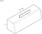
- FIG. 2 is a perspective view illustrating a display device for a vehicle according to an embodiment of the present disclosure.
- FIG. 3 is a perspective view illustrating a display device for a vehicle in which a state of FIG. 2 is changed.
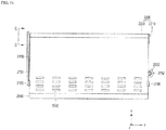
- FIG. 4 is a front view illustrating a display device for a vehicle according to an embodiment of the present disclosure.
- FIG. 5 is a cross-sectional view taken along the line AA of FIG. 4 .
- FIG. 6 is a view taken along the line BB of FIG. 4 .
- the display device for a vehicle may include a first frame 2100, a second frame 2200, a first roller 2310, a second roller 2320, and a flexible display 2400.
- the first frame 2100 may be provided to be fixed to a dashboard 10 of a vehicle.
- a groove for accommodating the display device for a vehicle is formed in the dashboard 10 of the vehicle, and the first frame 2100 may be disposed in an appropriate position in the groove.
- the first frame 2100 may be fixedly coupled to the dashboard 10 by being screwed, forcibly fitted, or appropriately coupled to the dashboard 10.
- the second frame 2200 may be provided to be movable in a first direction with respect to the first frame 2100.
- the second roller 2320 is rotatably coupled to the second frame 2200 through a pin so that as the second frame 2200 moves in the first direction, the second roller 2320 also moves in the first direction.
- the first direction may be an up-down direction of the vehicle or a direction inclined with respect to the up-down direction at a predetermined angle from the up-down direction.
- the first direction may be a direction which is substantially parallel to a front surface of the flexible display 2400.
- the first direction may be appropriately adjusted for the convenience of a driver who watches the flexible display 2400.
- the first roller 2310 may be provided to be spaced apart from the first frame 2100.
- the first roller 2310 is not coupled to the first frame 2100, and may be spaced apart from the first frame 2100 to be rotatable.
- the first roller 2310 is provided to have a bar shape of which the length direction is perpendicular to the first direction to support the flexible display 2400, a support bar 2550, or a chain 2520 in a width direction of the flexible display 2400, the support bar 2550, or the chain 2520, that is, a direction perpendicular to the first direction.
- the second roller 2320 is rotatably coupled to the second frame 2200, and may move in the first direction in accordance with the movement of the second frame 2200.
- the second roller 2320 is provided to have a bar shape of which the length direction is perpendicular to the first direction to support the flexible display 2400,in a width direction of the flexible display 2400, that is, a direction perpendicular to the first direction.
- the second frame 2200 may include a pair of bodies 2210 and a connection bar 2220.
- the bodies 2210 are provided as a pair, and are coupled to the second roller 2320 through a pin to support both sides of the second roller 2320. Accordingly, the second roller 2320 is rotatably coupled to the bodies 2210 and may move in the first direction as the second frame 2200 moves in the first direction.
- connection bar 2220 may connect the pair of bodies 2210 to each other.
- the pair of bodies 2210 and the connection bar 2220 may be integrally manufactured. Further, the connection bar 2220 may serve to bring the flexible display 2400 into close contact with the second roller 2320.
- the flexible display 2400 is disposed in a space formed between in an inner side surface of the connection bar 2220 and a surface of the second roller 2320, and the flexile display 2400 is guided by the inner side surface of the connection bar 2220 to be in close contact with the surface of the second roller 2320.
- a degree of close contact between the flexible display 2400 and the surface of the second roller 2320 may be adjusted by appropriately adjusting the interval of the space.
- One surface of the flexible display 2400 may be designed to be in direct contact with the surface of the second roller 2320.
- the flexible display 2400 and the second roller 2320 may not be in direct contact with each other.
- a size between the inner side surface of the connection bar 2220 and the surface of the second roller 2320 may be appropriately selected in consideration of a thickness of the back plate 2530.
- the back plate 2530 will be described in more detail below.
- the body 2210 may be fixedly coupled to a moving plate 2510.
- the moving plate 2510 moves in the first direction so that as the moving plate 2510 moves, the second frame 2200 and the second roller 2320, which is coupled to the second frame 2200, may move in the first direction together.
- the flexible display 2400 is partially wound around the second roller 2320 and bent by the second roller 2320, and one end portion of the flexible display 2400 is fixed to the first frame 2100.
- the flexible display 2400 is formed of a flexible material, and thus can be wound around the second roller 2320.
- the flexible display 2400 may be bent by the second roller 2320.
- the flexible display 2400 is bent at a portion thereof which is in close contact with the second roller 2320, and maintains a flat plane shape which is not bent in the remaining portion.
- the flexible display 2400 may be bent by the third roller 2330 at a portion of the flexible display 2400 which is in close contact with the third roller 2330 which will be described below.
- the flexible display 2400 refers to a durable display which is manufactured on a thin and flexible substrate which can be bent, curved, folded, twisted, or rolled like paper while maintaining a characteristic of a flat panel display, and is light and not easily broken.
- FIG. 7 is a front view illustrating a display device for a vehicle in which a state of FIG. 4 is changed.
- FIG. 8 is a cross-sectional view taken along the line AA of FIG. 7 .
- the flexible display 2400 may be provided such that an externally exposed area of the front surface is increased as a distance between the first roller 2310 and the second roller 2320 is increased.
- the externally exposed area of the flexible display 2400 may be defined as an area of a portion which is exposed outwardly from the dashboard 10 of the flexible display 2400 and is seen by a driver and passengers of the vehicle.
- FIGS. 2 , 4 , and 5 illustrate a state in which the externally exposed area of the flexible display 2400 is relatively small.
- FIGS. 3 , 7 , and 8 illustrate a state in which the externally exposed area of the flexible display 2400 is relatively large.
- the second roller 2320 moves in the first direction in the state of FIG. 5 such that the distance between the first roller 2310 and the second roller 2320 is increased to be in the state of FIG. 8 .
- one end portion of the flexible display 2400 is fixed to the first frame 2100 which does not move in the first direction so that a portion of the flexible display 2400 fixed to the first frame 2100 does not move in the first direction.
- the externally exposed area of the flexible display 2400 may be increased.
- the flexible display 2400 when the second roller 2320 moves in the first direction to be away from the first roller 2310, the flexible display 2400 is switched from the first state to the second state, and when the second roller 2320 moves in the first direction to be close to the first roller 2310, the flexible display 2400 may be switched from the second state to the first state.
- FIGS. 2 , 4 , and 5 illustrate the flexible display 2400 in the first state and FIGS. 3 , 7 , and 8 illustrate a flexible display 2400 in the second state.
- the externally exposed area of the front surface of the flexible display 2400 is larger in the second state than in the first state.
- the externally exposed area of the flexible display 2400 when a distance between the first roller 2310 and the second roller 2320 in the first direction is reduced, the externally exposed area of the flexible display 2400 is decreased, and when the distance between the first roller 2310 and the second roller 2320 in the first direction is increased, the externally exposed area of the flexible display 2400 may be increased.
- the display device for a vehicle may further include a moving part 2500 and a guider 2600.
- the moving part 2500 may serve to move the second roller 2320 in the first direction.
- the guider 2600 may serve to guide the movement of the moving part 2500.
- the moving part 2500 may include a moving plate 2510 and a support bar 2550.
- a chain 2520 may be used to replace the support bar 2550.
- the support bar 2550 will be described first, and the chain 2520 will be described below with reference to a separate drawing.
- the moving plate 2510 may be provided as a rigid material, and one end portion of the moving plate 2510 is fixedly coupled to the second frame 2200.
- the moving plate 2510 may be provided to move in the first direction as the second roller 2320 moves in the first direction.
- the second roller 2320 moves in the first direction together with the second frame 2200 so that the moving plate 2510 may move in the first direction as the second frame 2200 moves in the first direction.
- a flat portion of the flexible display 2400 may be in close contact with one surface of the moving plate 2510, and thus the flat portion of the flexible display 2400 may be maintained by the moving plate 2510.
- One end portion of the support bar 2550 may be coupled to the moving plate 2510.
- the support bar 2550 and the moving plate 2510 may be coupled to each other by an adhesive.
- the support bar 2550 When the support bar 2550 is unfolded, the support bar 2550 may have an entirely plate shape, but may be bent by the first roller 2310.
- the support bar 2550 may move while partially being wound around the first roller 2310. As illustrated in FIGS. 5 and 8 , as the second roller 2320 is far from the first roller 2310, the support bar 2550 moves in the first direction to be close to the first roller 2310 and is bent by the first roller 2310 so that a traveling direction is changed to 180 degrees, and the support bar 2550 may move in the first direction to be away from the first roller 2310.
- the support bar 2550 may be provided to support at least a part of a rear surface of the flexible display 2400. Referring to FIG. 8 , when the second roller 2320 is far from the first roller 2310 in the first direction, a part of the support bar 2550, that is, a portion adjacent to a portion coupled to the moving plate 2510, is bent by the first roller 2310 and changes direction to move in the same direction as the second roller 2320. In this case, a part of the rear surface of the flexible display 2400 may be supported.
- a part of the flexible display 2400 may be provided to be in close contact with the moving plate 2510 or the support bar 2550.
- a part of the flexible display 2400 may be provided to be in close contact with the moving plate 2510 or the chain 2520.
- the support bar 2550 may be provided as a flexible material so as to be bendable, and may include a base 2551 and a support 2552.
- the base 2551 and the support 2552 may be integrally manufactured, or in another embodiment, the support 2552 may be attached to the base 2551 to form the support bar 2550. In this case, the base 2551 and the support 2552 may be formed of the same material.
- the support bar 2550 may be coupled at the base 2551.
- the support 2552 has a trapezoidal cross-section, and referring to FIG. 5 , may be formed to have a bar shape perpendicular to the first direction.
- a plurality of supports 2552 may be provided, and the supports 2552 may be disposed at regular intervals in a moving direction of the support bar 2550.
- the supports 2552 may be appropriately formed to have a trapezoidal cross-section so that when the supports 2552 are wound around the first roller 2310 and are bent, no interference between adjacent supports 2552 due to the bending is caused.
- the display device for a vehicle may further include a third roller 2330.
- the third roller 2330 is rotatably coupled to the second frame 2200, and may support the flexible display 2400 such that a part of the flexible display 2400 is in close contact with the moving plate 2510.
- the third roller 2330 is provided to have a bar shape of which the length direction is perpendicular to the first direction to support the flexible display 2400 in a width direction of the flexible display 2400, that is, a direction perpendicular to the first direction.
- the second roller 2320 and the third roller 2330 are spaced apart from each other, and a space may be formed therebetween.
- the flexible display 2400 may be disposed to pass through the space.
- the flexible display 2400 is supported by the second roller 2320 and the third roller 2330, and the flexible display 2400 may be more effectively in close contact with the moving plate 2510.
- the flexible display 2400 can be easily bent or curved.
- the flexible display 2400 is caused to be in close contact with the moving plate 2510 using the second roller 2320 and the third roller 2330 so that a portion of the flexible display 2400 corresponding to the moving plate 2510 may ensure a plane which is not bent or curved. Therefore, the flexible display 2400 may provide an image with an improved image quality to the driver.
- the third roller 2330 may be rotatably coupled to the body 2210 of the second frame 2200 together with the second roller 2320. Therefore, the third roller 2330 may move in the first direction together with the second roller 2320 as the second roller 2320 moves in the first direction. In this case, the distance between the second roller 2320 and the third roller 2330 may be constantly maintained regardless of the movement in the first direction.
- the second roller 232 moves in the first direction, regardless of the increase or decrease of the externally exposed area of the flexible display 2400, the second roller 2320 and the third roller 2330 may effectively cause the flexible display 2400 to be in close contact with the moving plate 2510.
- FIG. 9 is a perspective view illustrating some components of a display device for a vehicle according to an embodiment of the present disclosure.
- FIG. 10 is a perspective view illustrating a display device for a vehicle in which a state of FIG. 9 is changed.
- FIGS. 9 and 10 some components of the display device for a vehicle are omitted.
- the guider 2600 may include a connector 2610, a first control bar 2620, a second control bar 2630, and an internal plate 2640.
- the connector 2610 may be coupled to one end of the flexible display 2400.
- the flexible display 2400 may be coupled to the connector 2610 by an adhesive.
- the connector 2610 may move in the first direction in accordance with the rotation of the first control bar 2620.
- the connector 2610 is disposed such that the length direction is perpendicular to the first direction so as to guide the flexible display 2400 to move in the first direction while having the same position in the width direction, that is, a direction perpendicular to the first direction.
- One end of the first control bar 2620 is coupled to the connector 2610, and is movable with respect to the connector 2610 in a direction perpendicular to the first direction. Further, the first control bar 2620 may be provided to rotate as the second roller 2320 moves in the first direction.
- the first control bar 2620 may rotate in a clockwise direction or a counterclockwise direction to pull the connector 2610.
- the first controller bar 2620 pulls the connector 2610 regardless of the position of the second roller 2320 in the first direction such that the degree of close contact between the flexible display 2400 and the moving plate 2510, the second roller 2320, or the third roller 2330 may be increased.
- One end of the second control bar 2630 is coupled to the other end of the first control bar 2620, and the second control bar 2630 may be provided to rotate as the second roller 2320 moves in the first direction.
- the first control bar 2620 and the second control bar 2630 may be rotatably coupled to each other.
- the other end of the second control bar 2630 may be coupled to an end portion of the support bar 2550 or the chain 2520.
- the second control bar 2630 rotates in a clockwise direction or a counterclockwise direction to pull the support bar 2550 or the chain 2520.
- the second control bar 2630 pulls the support bar 2550 or the chain 2520 regardless of the position of the second roller 2320 in the first direction such that the degree of close contact between the support bar 2550 or the chain 2520 and the first roller 2310 may be increased.
- the first control bar 2620 and the second control bar 2630 need to have a restoring force with respect to rotation so as to reduce an angle formed by the first control bar 2620 and the second control bar 2630.
- a second elastic part 2720 may be disposed at a portion where the first control bar 2620 and the second control bar 2630 are coupled.
- the second elastic part 2720 will be described below in more detail with reference to the drawings.
- the internal plate 2640 is fixed to the first frame 2100, and the coupling portion of the first control bar 2620 and the second control bar 2630 passes through the internal plate.
- the internal plate 2640 may be provided with a second slot 2641 to be described below, and the internal plate 2640 may guide the movement of the coupling portion of the first control bar 2620 and the second control bar 2630 using the second slot 2641.
- a first slot 2611, a second slot 2641, and a third slot 2524 may be provided.
- the connector 2610 may include the first slot 2611 into which a first protrusion 2621 protruding from one end of the first control bar 2620 is inserted.
- the first slot 2611 has a length direction formed to be perpendicular to the first direction, and guides the movement of the first control bar 2620 with respect to the connector 2610.
- one end of the first control bar 2620 is coupled to the first slot 2611 so as to move in a direction perpendicular to the first direction, and may be guided by the first slot 2611 to be moved.
- the internal plate 2640 may include the second slot 2641 into which the coupling portion of the first control bar 2620 and the second control bar 2630 is inserted.
- the second slot 2641 guides the movement of the coupling portion.
- the first control bar 2620 and the second control bar 2630 are rotatably coupled to each other, and the coupling portion is guided by the second slot 2641 which is formed to pass through the internal plate 2640 to be moved on the internal plate 2640.
- the second slot 2641 may be formed to have an appropriate curvature in consideration of a designed movement of the first control bar 2620 and the second control bar 2630.
- the support bar 2550 or the chain 2520 may include the third slot 2524 into which a second protrusion 2631 protruding from one end of the second control bar 2630 is inserted.
- the third slot 2525 has a length direction formed to be perpendicular to the first direction, and guides the movement of the second control bar 2630 with respect to the chain 2520.
- one end of the second control bar 2630 is coupled to the third slot 2524 so as to move in a direction perpendicular to the first direction, and may be guided by the third slot 2524 to be moved.
- the moving part 2500 may further include a back plate 2530.
- the back plate 2530 may be disposed so as to be opposite to the flexible display 2400, and at least a part of the back plate may be formed of a metal plate having elasticity.
- the flexible display 2400 can be easily bent or curved.
- the back plate 2530 which is in close contact with the flexible display 2400, is provided on the rear surface of the flexible display 2400 so that the back plate 2530 supports the flexible display 2400 to ensure a flat surface of the flexible display 2400 which is not bent or curved. Therefore, the flexible display 2400 may provide an image with an improved image quality to the driver.
- the back plate 2530 is coupled to the flexible display 2400 with a size and a shape corresponding to the flexible display 2400 so as to move together with the flexible display 2400 as one body.
- a specific structure of the back plate 2530 will be described below in more detail with reference to the drawings.
- FIG. 11 is a front view illustrating a display device for a vehicle according to another embodiment of the present disclosure.
- FIG. 12 is a side view of FIG. 11 .
- FIG. 13 is a view taken along the line CC of FIG. 11 .
- the display device for a vehicle may further include a guide bar 2730.
- the guide bar 2730 is provided to be fixed to the first frame 2100, and has a length direction disposed in the first direction and includes a guide rail 2731 to which the protruding portion 2230 of the second frame 2200 is coupled.
- the guide bar 2730 is formed of a rigid material, and one side of the guide bar 2730 is fixed to the first frame 2100 such that the second frame 2200 and the second roller 2320 may be stably supported to move in the first direction.
- the movement of the second frame 2200 and the second roller 2320 in the first direction is stably supported by the guide bar 2730 so that warpage and breakage of the flexible display 2400 and breakage or erroneous operation of the display device for a vehicle caused when the second frame 2200 and the second roller 2320 unstably move in the first direction can be effectively suppressed.
- the moving part 2500 may further include a first magnet 2540.
- the first magnet 2540 is disposed in a part of the flexible display 2400 to couple the flexible display 2400 to the back plate 2530.
- first magnets 2540 are provided, and an appropriate number of first magnets 2540 may be aligned in a part of the flexible display 2400 horizontally and vertically. In this case, a portion of the flexible display 2400 which is not bent by the second roller 2320 may be selected as a portion of the flexible display 2400 which includes the first magnets 2540.
- the first magnets 2540 may be provided to be bonded to the rear surface of the flexible display 2400, that is, a surface which is opposite to the back plate 2530, by an adhesive.
- the flexible display 2400 and the back plate 2530 are firmly coupled to each other by the first magnets 2540 so that the back plate 2530 can be effectively suppressed from being pushed against the flexible display 2400 due to the repeated movement of the flexible display 2400.
- the size of the externally exposed area of the flexible display 2400 in the display device for a vehicle may be manually changed by the driver. For example, when the driver lifts up the front surface of the flexible display 2400, the first roller 2310 ascends to increase the externally exposed area of the flexible display 2400. In contrast, when a driver pushes down the front surface of the flexible display 2400, the first roller 2310 descends to reduce the externally exposed area of the flexible display 2400.
- the magnitude of a restoring force of the second elastic part 2720 needs to be appropriately adjusted.
- the display device for a vehicle may include an actuator 2650 which automatically changes the size of the externally exposed area of the flexible display 2400. As illustrated in FIGS. 11 and 12 , the display device for a vehicle may further include the actuator 2650 which operates the guider 2600.
- the actuator 2650 may include a rack gear 2651, a pinion gear 2652, and a motor 2653.
- the rack gear 2651 is formed on the moving plate 2510, and a length direction thereof is disposed to be parallel to the first direction.
- the pinion gear 2652 may be disposed to be engaged with the rack gear 2651.
- a casing may be provided to bring the pinion gear 2652 and the rack gear 2651 into close contact with each other.
- the motor 2653 may be provided to rotate the pinion gear 2652.
- the motor 2653 may be fixed to an empty space of the dashboard 10 of the vehicle or the display device for a vehicle.
- the pinion gear 2652 is disposed at a rotational axis of the motor 2653 such that the pinion gear 2652 rotates by the rotation of the motor 2653 and the rack gear 2651, which is engaged with the pinion gear 2652, moves in the first direction. Therefore, the moving plate 2510 on which the rack gear 2651 is formed may move in the first direction.
- the moving plate 2510 moves in the first direction and the first control bar 2620 and the second control bar 2630 may rotate around the coupling portion.
- the moving plate 2510 moves in the first direction
- the second frame 2200 and the second roller 2320 move in the first direction, and thus the externally exposed area of the flexible display 2400 may be increased or reduced.
- the controller 180 provided in the display device for a vehicle is electrically connected to the motor 2653, and may control the operation of the motor 2653 such that the externally exposed area of the flexible display 2400 is increased or reduced.
- the display device for a vehicle may further include a hall sensor 2800 and a second magnet 2900.
- the hall sensor 2800 may be provided to be fixed to the first frame 2100.
- the second magnet 2900 may be provided to be fixed to the second frame 2200. Therefore, the hall sensor 2800 is fixed, and the second magnet 2900 may move together with the second frame 2200 in the first direction.
- the hall sensor 2800 may be connected to the controller 180.
- the hall sensor 2800 senses a distance from the second magnet 2900 so that the controller 180 provided in the display device for a vehicle can determine the externally exposed area of the flexible display 2400.
- the hall sensor 2800 senses a change in magnetic field of the second magnet 2900, and the controller 180 ascertains the distance between the hall sensor 2800 and the second magnet 2900 in the first direction based on the change in magnetic field.
- the controller 180 may determine the externally exposed area of the flexible display 2400 based on the distance between the hall sensor 2800 and the second magnet 2900 in the first direction.
- FIG. 14 is a perspective view illustrating a chain 2520 according to an embodiment of the present disclosure.
- FIG. 15 is a view for explaining an operation of a chain 2520 according to an embodiment of the present disclosure.
- the chain 2520 is provided instead of the support bar 2550, and performs the same function as the support bar 2550. Therefore, one end portion of the chain 2520 is coupled to the moving plate 2510 and is bent by the first roller 2310, and supports at least a part of the rear surface of the flexible display 2400.
- the chain 2520 may be provided as a metal, and one end portion of the chain 2520 has a pin.
- the pin is embedded into the moving plate 2510 so that the chain 2520 and the moving plate 2510 may be coupled to each other.
- the coupling method is not limited thereto.
- the chain 2520 may include a first link 2521, a second link 2522, and a link pin 2523.
- a plurality of first links 2521 and a plurality of second links 2522 are provided.
- the plurality of first links 2521 are disposed along the front-rear direction, and the plurality of second links 2522 are also disposed along the front-rear direction.
- the first links 2521 and the second links 2522 are fastened to each other.
- a first link hole 2521a is formed in the first link 2521 and a second link hole 2522a is formed in the second link 2522, and the link pin 2523 is coupled to the first link hole 2521a and the second link hole 2522a by being inserted therein.
- the first link 2521 and the second link 2522 may relatively rotate with the link pin 2523 that fastens them serving as a rotational axis.
- first link 2521 two identical first link holes 2521a are formed to be spaced apart from each other, and in the second link 2522, two identical second link holes 2522a are formed to be spaced apart from each other.
- the link pin 2523 has a circular shape in cross-section
- the second link hole 2522a also has a circular shape in cross-section.
- the first link hole 2521a may be formed to have a slot hole shape with a longer diameter in the length direction of the chain 2520. That is, the first link hole 2521a is formed such that a diameter d2 of the length direction is greater than a diameter d1 of the thickness direction (by a).
- the first link hole 2521a is formed such that a diameter d2 of a length direction is 0.2 mm larger than a diameter d1 of a thickness direction.
- the first link hole 2521a is formed to have a long hole shape having a large diameter in the length direction of the chain 2520 so that length compensation of the chain 2520 can be achieved.
- the display device for a vehicle may further include a third frame 2003.
- the third frame 2003 is fixedly coupled to a lower end of the internal plate 2640, and the first roller 2310 is rotatably coupled to the third frame 2003.
- each third frame 2003 is fixedly coupled to both sides of the lower end of the internal plate 2640. Accordingly, both ends of the first roller may be rotatably coupled to the third frame 2003.
- the third frame 2003 allows the first roller 2310 to be rotatably coupled to the internal plate 2640, which does not move in the first direction. Accordingly, the chain 2620 may be bent by the first roller 2310 and simultaneously move in the first direction while being stably supported by the first roller 2310.
- the structure of the third frame 2003 may also be employed by the display device for a vehicle which includes the support bar 2550.
- FIG. 16 is a view for explaining an operation of a first elastic part 2710 according to an embodiment of the present disclosure.
- FIG. 17 is a perspective view illustrating a first elastic part 2710 according to an embodiment of the present disclosure.
- the display device for a vehicle may include the first elastic part 2710 instead of the third frame 2003.
- the first elastic part 2710 is mounted in the internal plate 2640 at a portion where the internal plate 2640 and the first roller 2310 are opposite to each other, and elastically supports the second roller 2320.
- the first elastic part 2710 may include an elastic body 2711 and a pusher 2712.
- the pusher 2712 may include a protrusion to mount the elastic body 2711. Referring to FIG. 16 , a hole into which the elastic body 2711 and the protrusion of the pusher 2712 are inserted may be formed at a lower end of the internal plate 2640.
- the elastic body 2711 may be formed to have a coil spring shape.
- the elastic body 2711 is configured to store an elastic force in a compressed state, and apply pressure to the first roller 2310 in this state.
- the elastic body 2711 may be provided to apply pressure to the first roller 2310 by means of the pusher 2712. In another embodiment, only the elastic body 2711 may be provided to be mounted at the lower end of the internal plate 2640, and apply pressure to the first roller 2310 without using the pusher 2712.
- Pressure may be applied to the first roller 2310 by the first elastic part 2710 so that the first roller 2310 is in close contact with the chain 2520, and thus the chain 2520 may be bent by the first roller 2310 and simultaneously move in the first direction while being stably supported by the first roller 2310.
- the structure of the first elastic part 2710 may also be employed by the display device for a vehicle which includes the support bar 2550.
- the guider 2600 may further include a second elastic part 2720.
- FIG. 18 is a view for explaining an operation of a second elastic part 2720 according to an embodiment of the present disclosure.
- the second elastic part 2720 is disposed in the coupling portion of the first control bar 2620 and the second control bar 2630 to elastically support the rotation of the first control bar 2620 and the second control bar 2630.
- the second elastic part 2720 may be provided as a torsion spring.
- the second elastic part 2720 may be mounted to pass through the coupling portion where the first control bar 2620 and the second control bar 2630 rotate with each other, and one end of the second elastic part 2720 is fixedly coupled to the first control bar 2620 and the other end is fixedly coupled to the second control bar 2630.
- the second elastic part 2720 may be provided to apply a rotational force to the first control bar 2620 and the second control bar 2630 so as to increase an angle between the first control bar 2620 and the second control bar 2630.
- a force required for the first roller 2310 to smoothly ascend in the first direction may be provided to the display device for a vehicle.
- FIG. 19 illustrates a back plate 2530 according to an embodiment of the present disclosure.
- the back plate 2530 may be formed of a metal plate having elasticity.
- the back plate 2530 may be configured to include a super elastic metal.
- the back plate 2530 may allow the flexible display 2400 to be smoothly elastically deformed and elastically restored.
- the back plate 2530 may be formed as a relatively thin plate.
- the back plate 2530 may be formed to have an arbitrary thickness within a range of 0.05 to 0.2 mm, and may be formed to have a thickness of 0.1 mm.
- the back plate 2530 may be formed of an integrated metal plate as a whole and be divided into two or more areas. Specifically, the back plate 2530 may be configured to include a fixed area 2530a and a transformable area 2530b.
- the fixed area 2530a overlaps a portion of the flexible display 2400 which is not bent.
- the back plate 2530 may be formed as a flat metal plate as a whole.
- Through holes 2535 may be formed in portion of the back plate 2530 which corresponds to the roller, that is, the transformable area 2530b.
- the transformable area 2530b overlaps a bending portion of the flexible display 2400.
- a plurality of through holes 2535 are formed to be long in the width direction (left-right direction). That is, in the transformable area 2530b, a plurality of through holes which pass through the thickness direction is formed in the back plate 2530.
- the back plate 2530 may be formed to be symmetrical in the left-right direction.
- the transformable area 2530b in which the plurality of through holes 2535 are formed may include edges 2531, horizontal connectors 2532, and first vertical connectors 2533.
- the edges 2531 are divided into a plurality of edges to form a left edge and a right edge of the back plate 2530.
- the edges 2531 have a predetermined length along the length direction, and are spaced apart from each other.
- the horizontal connectors 2532 extend from the edges 2531 in the width direction. Two horizontal connectors 2532 extend from one edge 2531.
- the first vertical connector connects two horizontal connectors 2532 which extend from different edges 2531 to each other. That is, one first vertical connector 2533 connects two horizontal connectors 2532 extending from two adjacent edges 2531 and are adjacent to each other.
- the first vertical connectors 2533 may be repeatedly formed along the width direction (left-right direction), and the first vertical connectors 2533 may be spaced apart from each other at regular intervals.
- Second vertical connectors 2534 may be formed in the transformable area 2530b, and one second vertical connector 2534 connects two horizontal connectors 2532 extending from the same edge 2531.
- the second vertical connectors 2534 may be repeatedly formed along the width direction (left-right direction), and the second vertical connectors 2534 may be spaced apart from each other at regular intervals.
- the transformable area 2530b may be easily bent with respect to the rotation axis of the width direction.
- the edges 2531 and the first vertical connectors 2533 may be deformed to be spaced apart from each other in the length direction with respect to the horizontal connectors 2532, and the length of the transformable area 2530b may be increased over the entire area of the transformable area 2530b.
- the transformable area 2530b is elastically recovered to its original state.
- the first vertical connectors 2533 and the second vertical connectors 2534 may be deformed to be spaced apart from each other in the length direction with respect to the horizontal connector 2532, and the length of the transformable area 2530b may be increased over the entire area of the transformable area 2530b.
- the transformable area 2530b is elastically recovered to its original state.
- the bending area of the flexible display 2400 may be more flexibly deformed.
- the flexible display 2400 is bent at a portion adjacent to the second roller 2320, the flexible display 2400 can easily be elastically deformed, and spring-back can easily be controlled.
- the flexible display 2400 may be elastically deformed within a predetermined range along the length direction.
- the size of the screen to be displayed cab be adjusted in accordance with the convenience of the user.
- the controller 180 provided in the above-described display device for a vehicle may control the operation of the display device for a vehicle such that the display device for a vehicle has an externally exposed area set by each user or based on characteristics of each device provided in the vehicle.
- the controller 180 may control the externally exposed area of the display device for a vehicle based on an input value of the user. That is, the user inputs a numerical value for the externally exposed area of the display device for a vehicle to the input interface 120, and the controller 180 controls the externally exposed area of the display device for a vehicle in accordance with the inputted numerical value so that the user may conveniently watch displayed images or information from a screen with a desired size.
- the flexible display 2400 may reproduce a screen for controlling devices provided in the vehicle, and the controller 180 may control the externally exposed area to be varied in accordance with the characteristics of the respective devices provided in the vehicle.
- the flexible display 2400 may reproduce a navigation screen, a screen for manipulating an air conditioner, and a screen for controlling a driving device to display a brake or a speedometer.
- the controller 180 may control the display device for a vehicle such that the externally exposed area of the flexible display 2400 is increased as compared with other cases.
- the controller 180 may recognize a face of the user which is in the driver's seat through a camera provided in the display device for a vehicle so as to identify the user and control the size of the externally exposed area of the flexible display 2400 based on a value set for each identified user.
Landscapes
- Engineering & Computer Science (AREA)
- Mechanical Engineering (AREA)
- Chemical & Material Sciences (AREA)
- Transportation (AREA)
- Combustion & Propulsion (AREA)
- Theoretical Computer Science (AREA)
- General Engineering & Computer Science (AREA)
- General Physics & Mathematics (AREA)
- Physics & Mathematics (AREA)
- Computer Hardware Design (AREA)
- Human Computer Interaction (AREA)
- Marketing (AREA)
- Accounting & Taxation (AREA)
- Business, Economics & Management (AREA)
- Fittings On The Vehicle Exterior For Carrying Loads, And Devices For Holding Or Mounting Articles (AREA)
Abstract
Description
- This application claims the benefit of an earlier filing date of and the right of priority to Korean Application No.
10-2020-0003553 - The present disclosure relates to a display device for a vehicle, and more particularly, to a display device for a vehicle to which a flexible display is applied.
- The description in this section merely provides background information on embodiments of the present disclosure and does not necessarily constitute related art.
- As flexible displays which are bendable while displaying image information are developed, foldable-type devices to which a flexible display is applied are being studied and developed.
- In such devices, the flexible display has a folding structure so that a size of a screen to be displayed can be conveniently modified, space is saved, portability is increased, and a large size display can be implemented.
- Other devices using a flexible display and which are being studied and developed include rollable or bendable devices having a structure in which the display is wound. In such devices, the flexible display can be wound to reduce a size or an area of the entire display, and the flexible display can be unwound to increase size or the area of the entire display.
- Further, on a vehicle dashboard, a display device which provides convenience to a user such as a driver to assist in safe driving of the vehicle, and displays information about the driving of the vehicle and devices provided in the vehicle, is provided.
- When the display device for a vehicle is implemented as a flexible display, space of the dashboard of a vehicle having a comparatively small space can be saved, and a display with a large screen which is convenient for a user may be provided. Accordingly, there is a need for studies regarding such display devices.
- The present disclosure is directed to providing a display device for a vehicle to which a flexible display is applied.
- The present disclosure is further directed to providing a display device for a vehicle for which a screen size of a flexible display can be conveniently adjusted.
- Aspects of the present disclosure are not limited to the aspects described above, and other aspects that are not stated herein will be clearly understood by those skilled in the art from the following description.
- A display device for a vehicle according to an embodiment of the present disclosure includes a first frame, a second frame configured to be movable in a first direction with respect to the first frame, a first roller configured to be spaced apart from the first frame, a second roller configured to be rotatably coupled to the second frame and move in the first direction in accordance with movement of the second frame, and a flexible display configured to be partially wound around the second roller and bent by the second roller and have one end portion fixed to the first frame.
- The flexible display may be provided such that an externally exposed area on a front surface is increased as a distance between the first roller and the second roller is increased.
- The second frame may include a pair of bodies configured to be coupled to the second roller through a pin and support both sides of the second roller, and a connection bar configured to connect the bodies to each other and bring the flexible display into close contact with the second roller.
- The display device for a vehicle according to an embodiment may further include a moving part configured to move the second roller in the first direction, and a guider configured to guide the movement of the moving part.
- The moving part may include a moving plate configured to have one end portion which is coupled to the second frame and move in the first direction as the second roller moves in the first direction, and a chain configured to have one end portion coupled to the moving plate, be bent by the first roller, and support at least a part of a rear surface of the flexible display.
- The chain may include a first link in which a first link hole is formed, a second link in which a first link hole is formed, and a link pin configured to be inserted into the first link hole and the second link hole to connect the first link and the second link, and the first link hole is formed as a slot hole with a long diameter in a length direction of the chain.
- The flexible display may be provided such that a part thereof is in close contact with the moving plate or the chain.
- The display device for a vehicle according to an embodiment may further include a third roller configured to be rotatably coupled to the second frame and support the flexible display such that a part of the flexible display is in close contact with the moving plate.
- The third roller may move in the first direction together with the second roller as the second roller moves in the first direction.
- The guider may include a connector coupled to one end of the flexible display, a first control bar configured to have one end coupled to the connector and be movable in a direction perpendicular to the first direction with respect to the connector and rotate as the second roller moves in the first direction, a second control bar configured to have one end coupled to the other end of the first control bar and rotate as the second roller moves in the first direction, and an internal plate configured to be fixed to the first frame and allow a coupling portion of the first control bar and the second control bar to pass therethrough.
- The display device for a vehicle according to an embodiment may further include an actuator configured to operate the guider. The actuator may include a rack gear formed on the moving plate such that a length direction is disposed to be parallel to the first direction, a pinion gear disposed to be engaged with the rack gear, and a motor configured to rotate the pinion gear.
- As the pinion gear rotates, the moving plate moves in the first direction and the first control bar and the second control bar rotate around the coupling portion.
- The display device for a vehicle according to an embodiment may further include a first elastic part configured to be mounted on the internal plate to be disposed at a portion where the internal plate and the first roller are opposite to each other, and elastically support the second roller.
- The connector may include a first slot into which a first protrusion protruding from one end of the first control bar is inserted, which has a length direction formed to be perpendicular to the first direction and guides movement of the first control bar with respect to the connector. The internal plate may include a second slot into which a coupling portion of the first control bar and the second control bar is inserted, which guides the movement of the coupling portion. The chain may include a third slot into which a second protrusion protruding from one end of the second control bar is inserted, which has a length direction formed to be perpendicular to the first direction and guides movement of the second control bar with respect to the chain.
- The guider may further include a second elastic part configured to be disposed in the coupling portion of the first control bar and the second control bar to elastically support the rotation of the first control bar and the second control bar.
- The first frame may be provided to be fixed to the dashboard of the vehicle.
- The display device for a vehicle according to an embodiment may further include a guide bar configured to be fixed to the first frame, have a length direction disposed in the first direction, and include a guide rail to which a protruding portion of the second frame is coupled.
- The display device for a vehicle according to an embodiment may further include a hall sensor configured to be fixed to the first frame, and a second magnet configured to be fixed to the second frame. The hall sensor senses a distance from the second magnet so that a controller provided in the display device can determine an externally exposed area of the flexible display.
- The controller provided in the display device controls the operation of the display device such that the display device has an externally exposed area set by each user or based on characteristics of devices provided in the vehicle.
- A display device for a vehicle according to another embodiment of the present disclosure includes a first frame, a second frame configured to be movable in a first direction with respect to the first frame, a first roller configured to be spaced apart from the first frame in the first direction, a second roller configured to be rotatably coupled to the second frame and move in the first direction in accordance with movement of the second frame, and a flexible display configured to be partially wound around the second roller and bent by the second roller and have one end portion fixed to the first frame. When the second roller moves in the first direction to be away from the first roller, the flexible display is switched from a first state to a second state, and when the second roller moves in the first direction to be close to the first roller, the flexible display is switched from the second state to the first state.
- The flexible display may have an externally exposed area in the second state which is larger than that in the first state.
- According to embodiments of the present disclosure, the externally exposed area of the flexible display is manually adjusted by the user or automatically adjusted by the actuator. Accordingly, the size of the screen to be displayed can be adjusted in accordance with the convenience of the user.
- Further, according to the embodiments, the flexible display may be in close contact with the moving plate using the second roller and the third roller such that a portion of the flexible display corresponding to the moving plate may ensure a flat surface which is not bent or curved. Accordingly, the flexible display can provide an image with an improved image quality to the driver.
- Furthermore, according to the embodiments, a back plate which is in close contact with the flexible display is provided on a rear surface of the flexible display such that the back plate supports the flexible display to ensure a flat surface of the flexible display which is not bent or curved. Accordingly, the flexible display can provide an image with an improved image quality to the driver.
- Further, according to the embodiments, the movement of the second frame and the second roller in the first direction is stably supported by the guide bar. Accordingly, warpage and breakage of the flexible display and breakage or erroneous operation of the display device for a vehicle caused when the second frame and the second roller unstably move in the first direction can be effectively suppressed.
- Furthermore, according to the embodiments, the flexible display and the back plate are firmly coupled to each other by the first magnet. Accordingly, the back plate can be effectively suppressed from being pushed against the flexible display due to repeated movement of the flexible display.
- The above and other aspects, features, and advantages of the present disclosure will become apparent from the detailed description of the following aspects in conjunction with the accompanying drawings, in which:
-
FIG. 1 is a block diagram for explaining a display device for a vehicle according to an embodiment of the present disclosure; -
FIG. 2 is a perspective view illustrating a display device for a vehicle according to an embodiment of the present disclosure; -
FIG. 3 is a perspective view illustrating a display device for a vehicle in which a state ofFIG. 2 is changed; -
FIG. 4 is a front view illustrating a display device for a vehicle according to an embodiment of the present disclosure; -
FIG. 5 is a cross-sectional view taken along the line AA ofFIG. 4 ; -
FIG. 6 is a view taken along the line BB ofFIG. 4 ; -
FIG. 7 is a front view illustrating a display device for a vehicle in which a state ofFIG. 4 is changed; -
FIG. 8 is a cross-sectional view taken along the line AA ofFIG. 7 ; -
FIG. 9 is a perspective view illustrating some components of a display device for a vehicle according to an embodiment. -
FIG. 10 is a perspective view illustrating a display device for a vehicle in which a state ofFIG. 9 is changed; -
FIG. 11 is a front view illustrating a display device for a vehicle according to another embodiment of the present disclosure; -
FIG. 12 is a side view ofFIG. 11 ; -
FIG. 13 is a view taken along the line CC ofFIG. 11 ; -
FIG. 14 is a perspective view illustrating a chain according to an embodiment of the present disclosure; -
FIG. 15 is a view for explaining an operation of a chain according to an embodiment of the present disclosure; -
FIG. 16 is a view for explaining an operation of a first elastic part according to an embodiment of the present disclosure; -
FIG. 17 is a perspective view illustrating a first elastic part according to an embodiment of the present disclosure; -
FIG. 18 is a view for explaining an operation of a second elastic part according to an embodiment of the present disclosure; and -
FIG. 19 is a view illustrating a back plate according to an embodiment of the present disclosure. - Hereinbelow, embodiments will be described in greater detail with reference to the accompanying drawings. The embodiments may be modified in various ways and may have various forms, and specific embodiments will be illustrated in the drawings and will be described in detail herein. However, this is not intended to limit the embodiments to the specific embodiments, and the embodiment should be understood as including all modifications, equivalents, and replacements that fall within the spirit and technical scope of the embodiments.
- Terms such as "first," "second," and other numerical terms when used herein do not imply a sequence or order unless clearly indicated by the context. These terms are only used to distinguish one element from another. In addition, terms, which are specially defined in consideration of the configurations and operations of the embodiments, are given only to explain the embodiments, and do not limit the scope of the embodiments.
- In the description of the embodiment, in the case in which it is described as being formed on "on" or "under" of each element, "on" or "under" includes two elements directly contacting each other or one or more other elements being indirectly formed between the two elements. In addition, when expressed as "on" or "under", it may include not only upwards but also downwards with respect to one element.
- In addition, relational terms to be described below such as "on/over/up" and "beneath/under/down" may be used to discriminate any one subject or element from another subject or element without necessarily requiring or comprehending a physical or logical relationship or sequence of subjects or elements.
- Further, in the drawings, a rectangular coordinate system (x, y, z) may be used. In the drawings, an X-axis direction refers to a first direction.
-
FIG. 1 is a block diagram for explaining adisplay device 100 for a vehicle according to an embodiment of the present disclosure. - A
display device 100 for a vehicle according to an embodiment may, for example, be mounted on adashboard 10 of the vehicle to control various types of devices used to operate the vehicle, or to display information necessary to operate the vehicle and information necessary to provide convenience to occupants of the vehicle. - The
display device 100 for a vehicle includes awireless transceiver 110, aninput interface 120, asensor 140, anoutput interface 150, aninterface 160, amemory 170, acontroller 180, and apower supply 190. The components illustrated inFIG. 1 are not essential to implement the display device for a vehicle, and the display device for a vehicle described in the present specification may include more or fewer components than the components described above. - More specifically, the
wireless transceiver 110 among the components may include one or more modules which enable wireless communication between thedisplay device 100 for a vehicle and a wireless communication system, between thedisplay device 100 for a vehicle and anotherdisplay device 100 for a vehicle, or between thedisplay device 100 for a vehicle and an external server. Further, thewireless transceiver 110 may include one or more modules which connect thedisplay device 100 for a vehicle to one or more networks. - The
wireless transceiver 110 may include at least one of abroadcast receiving module 111, amobile communication module 112, awireless internet module 113, a short-range communication module 114, or aposition information module 115. - The
input interface 120 may include acamera 121 or an image input interface which inputs an image signal, amicrophone 122 or an audio input interface which inputs an audio signal, and a user input interface 123 (for example, a touch key or a push key (a mechanical key)) which receives information from a user. Voice data or image data collected by theinput interface 120 is analyzed to be processed as a control command of the user. - The
sensor 140 may include one or more sensors which sense at least one of information in the display device for a vehicle, surrounding environment information around the display device for a vehicle, or user information. For example, thesensor 140 may include at least one of aproximity sensor 141, anillumination sensor 142, a touch sensor, an acceleration sensor, a magnetic sensor, a G-sensor, a gyroscope sensor, a motion sensor, an RGB sensor, an infrared (IR) sensor, a finger scan sensor, an ultrasonic sensor, an optical sensor (for example, acamera 121 or a microphone 122), a battery gauge, an environment sensor (for example, a barometer, a hygrometer, a thermometer, a radiation sensor, a thermal sensor, and a gas sensor), or a chemical sensor (for example, an electronic nose, a healthcare sensor, and a biometric sensor). Further, the display device for a vehicle disclosed in the present specification may combine and utilize information sensed by at least two sensors among the above-mentioned sensors. - The
output interface 150 is intended to generate an output related to a visual, aural, or tactile stimulus, and may include at least one among adisplay 151, asound output interface 152, ahaptic module 153, and anoptical output interface 154. Thedisplay 151 may be configured as a touch screen by forming a mutual layered structure with a touch sensor or being formed integrally therewith. The touch screen simultaneously serves as auser input interface 123 which provides an input interface between thedisplay device 100 for a vehicle and the user and provides an output interface between thedisplay device 100 for a vehicle and the user. - The
interface 160 serves as a passage between various types of external devices which are connected to thedisplay device 100 for a vehicle. Theinterface 160 may include at least one of a wired/wireless headset port, an external charger port, a wired/wireless data port, a memory card port, a port which connects a device provided with an identification module, an audio input/output (I/O) port, a video input/output (I/O) port, or an earphone port. Thedisplay device 100 for a vehicle may perform appropriate control related to the connected external device in accordance with the connection of the external device to theinterface 160. - Further, the
memory 170 may store data which supports various functions of thedisplay device 100 for a vehicle. Thememory 170 may store a plurality of application programs (or applications) driven in thedisplay device 100 for a vehicle, data for operations of thedisplay device 100 for a vehicle, and instructions. At least some of the application programs may be downloaded via an external server through wireless communication. Further, at least some of the application programs for basic functions of thedisplay device 100 for a vehicle (for example, functions for receiving and making calls and receiving and sending messages) may be provided in thedisplay device 100 for a vehicle from the time of shipment. The application programs are stored in thememory 170, and installed in thedisplay device 100 for a vehicle to be driven by thecontroller 180 to perform operations (or functions) of thedisplay device 100 for a vehicle. - In addition to the operations related to the application programs, the
controller 180 may generally control overall operation of thedisplay device 100 for a vehicle. Thecontroller 180 may process signals, data, or information which is inputted or outputted through the above-described components, or drive the application programs stored in thememory 170 to provide or process appropriate information or functions to the user. - Further, in order to drive the application programs stored in the
memory 170, thecontroller 180 may control at least some of components described with reference toFIG. 1 . Moreover, thecontroller 180 may combine and operate at least two of components included in thedisplay device 100 for a vehicle to drive the application programs. - The
power supply 190 is applied with external power, and supplies the power to the components included in thedisplay device 100 for a vehicle under the control of thecontroller 180. At least some of the above-described components may operate in cooperation with each other to implement the operation, the control, or the control method of the display device for a vehicle according to various embodiments to be described below. Further, the operation, the control, or the control method of the display device for a vehicle may be implemented in the display device for a vehicle by driving at least one application program stored in thememory 170. - Hereinafter, prior to describing various embodiments implemented by the
display device 100 for a vehicle described above, the above-mentioned components will be described in more detail with reference toFIG. 1 . - First, the
wireless transceiver 110 will be described. Thebroadcast receiving module 111 of thewireless transceiver 110 receives a broadcast signal and/or broadcast-related information from an external broadcast management server through a broadcast channel. The broadcast channel may include a satellite channel and a ground wave channel. Two or more broadcast receiving modules for simultaneous broadcast reception or broadcast channel switching for at least two broadcast channels may be provided to thedisplay device 100 for a vehicle. - The broadcast management sever may refer to a server which generates and transmits a broadcast signal and/or broadcast related information or a server which is supplied with the previously generated broadcast signal and/or broadcast related information and transmits the broadcast signal and/or the broadcast related information to the display device for a vehicle. The broadcast signal includes not only a TV broadcast signal, a radio broadcast signal, and a data broadcast signal, but also a broadcast signal obtained by combining a TV broadcast signal or a radio broadcast signal with a data broadcast signal.
- The broadcast signal may be encoded according to at least one technical standard for transmitting and receiving a digital broadcast signal (or broadcast schemes, for example, ISO, IEC, DVB, or ATSC), and the
broadcast receiving module 111 may receive the digital broadcast signal using an appropriate method for the technical specification determined by the technical standard. - The broadcast-related information may refer to information related to a broadcast channel, a broadcast program, or a broadcast service provider. The broadcast-related information may also be provided through the mobile communication network. In this case, the broadcast-related information may be received by the
mobile communication module 112. - The broadcast-related information may exist in various types such as an electronic program guide of digital multimedia broadcasting (DMB) or an electronic service guide of a digital video broadcast-handheld (DVB-H). The broadcast signal and/or the broadcast-related information received by the
broadcast receiving module 111 may be stored in thememory 170. - The
modem 112 may transmit/receive a wireless signal to/from at least one among a base station, an external terminal, or a server on a mobile communication network established according to the technical standards or communication methods for mobile communication (for example, Global System for Mobile communication (GSM), Code Division Multi Access (CDMA), Code Division Multi Access 2000 (CDMA2000), Enhanced Voice-Data Optimized or Enhanced Voice-Data Only (EV-DO), Wideband CDMA (WCDMA), High Speed Downlink Packet Access (HSDPA), High Speed Uplink Packet Access (HSUPA), Long Term Evolution (LTE), and Long Term Evolution-Advanced (LTE-A)). - The wireless signal may include a voice call signal, a video call signal, or various types of data in accordance with transmission or reception of a text/multimedia message.
- The
wireless Internet module 113 refers to a module for wireless Internet access and may be built inside or outside thedisplay device 100 for a vehicle. Thewireless Internet module 113 may be configured to transmit/receive a wireless signal in a communication network according to wireless Internet technologies. - Wireless Internet technologies may include wireless LAN (WLAN), wireless fidelity (Wi-Fi), Wi-Fi direct, Digital Living Network Alliance (DLNA), wireless broadband (WiBro), Worldwide Interoperability for Microwave Access (WiMAX), High Speed Downlink Packet Access (HSDPA), High Speed Uplink Packet Access (HSUPA), Long Term Evolution (LTE), and Long Term Evolution-Advanced (LTE-A). The
wireless Internet module 113 may transmit or receive data in accordance with at least one wireless Internet technology, including Internet technologies which have not been described above. - From the viewpoint that the wireless Internet connection by WiBro, HSDPA, HSUPA, GSM, CDMA, WCDMA, LTE, LTE-A, etc. is performed through a mobile communication network, the
wireless Internet module 113 which performs the wireless Internet connection through the mobile communication network may be understood as a type of themobile communication module 112. - The short-
range communication module 114 may support short-range communication using at least one of Bluetooth™, infrared data association (IrDA), ultra wideband (UWB), ZigBee, Short-range Communication (NFC), wireless fidelity (Wi-Fi), Wi-Fi Direct, or Wireless Universal Serial Bus (Wireless USB). The shortrange communication module 114 may support wireless communication between thedisplay device 100 for a vehicle and the wireless communication system, between thedisplay device 100 for a vehicle and anotherdisplay device 100 for a vehicle, or between thedisplay device 100 for a vehicle and a network in which anotherdisplay device 100 for a vehicle (or external server) is located, through the short range wireless communication network. The short-range wireless communication network may be a short-range wireless personal communication network. - The
position information module 115 is a module for obtaining the position (or the current position) of a display device for a vehicle, and its representative examples include a global positioning system (GPS) module or a Wi-Fi module. For example, when a GPS module is utilized, the display device for a vehicle may obtain the position of the display device for a vehicle using a signal transmitted from a GPS satellite. As another example, when a Wi-Fi module is utilized, the display device for a vehicle may obtain the position of the display device for a vehicle based on information of a wireless access point (AP) which transmits and receives wireless signals to and from the Wi-Fi module. If necessary, theposition information module 115 may perform any function of another module of thewireless transceiver 110 to substitutionally or additionally obtain data on the position of the display device for a vehicle. As a module used to obtain a position (or a current position) of the display device for a vehicle, theposition information module 115 is not limited to a module which directly calculates or obtains the position of the display device for a vehicle. - Next, the
input interface 120 is provided to input image information (or signals), audio information (or signals), data, or an information input from the user, and in order to input the image information, thedisplay device 100 for a vehicle may include one or a plurality ofcameras 121. Thecamera 121 processes an image frame such as a still image or a moving image obtained by an image sensor in a video call mode or a photographing mode. The processed image frames may be displayed on thedisplay 151 or stored in thememory 170. The plurality ofcameras 121 provided in thedisplay device 100 for a vehicle may be disposed to form a matrix structure, and a plurality of pieces of image information having various angles or focal points may be inputted to thedisplay device 100 for a vehicle through thecameras 121 which forms the matrix structure. Further, thecameras 121 may be disposed to have a stereo structure to obtain a left image and a right image to implement a stereoscopic image. - The
microphone 122 processes an external sound signal as electronic voice data. The processed voice data may be utilized in various forms in accordance with a function which is being performed by thedisplay device 100 for a vehicle (or an application program which is being executed). In themicrophone 122, various noise removal algorithms which remove noise generated during the process of receiving the external sound signal may be implemented. - The
user input interface 123 receives information from the user, and when the information is inputted through theuser input interface 123, thecontroller 180 controls the operation of thedisplay device 100 for a vehicle so as to correspond to the inputted information. Theuser input interface 123 may include a mechanical input means (or a mechanical key, for example, a button located on a front, rear, or side surface of thedisplay device 100 for a vehicle, a dome switch, a jog wheel, a jog switch, or the like) and a touch type input means. As one example, the touch type input interface may include a virtual key, a soft key, or a visual key displayed on the touch screen via a software process, or may include a touch key disposed on a portion other than the touch screen. The virtual key or the visual key may be displayed on the touch screen in various shapes, and for example, may be formed by graphics, text, icons, video, or a combination thereof. - The
sensor 140 senses at least one of information in the display device for a vehicle, surrounding environment information around the display device for a vehicle, or user information, and generates a sensing signal corresponding to the information. Thecontroller 180 may control the driving or the operation of thedisplay device 100 for a vehicle or perform data processing, functions, or operations related to the application program installed in thedisplay device 100 for a vehicle, based on the sensing signal. Representative sensors among the various sensors which may be included in thesensor 140 will be described in more detail below. - First, the
proximity sensor 141 is a sensor which senses the presence of an object approaching a predetermined sensing surface or nearby objects, using an electromagnetic field force or infrared ray without any mechanical contact. Theproximity sensor 141 may be disposed in an internal area of the mobile terminal, which is enclosed by the above-described touch screen, or in the vicinity of the touch screen. - Examples of the
proximity sensor 141 may include a transmission type photoelectric sensor, a direct reflection type photoelectric sensor, a mirror reflection type photoelectric sensor, a high frequency oscillation type proximity sensor, a capacitive proximity sensor, a magnetic proximity sensor, and an infrared proximity sensor. When the touch screen is a capacitive type, theproximity sensor 141 may be configured to detect the proximity of the object with a change in the electric field in accordance with the proximity of the object having conductivity. In this case, the touch screen (or the touch sensor) itself may be classified as a proximity sensor. - For convenience of description, when an object approaches the touch screen without contacting the touch screen, and it is recognized that the object is located above the touch screen, it is referred to as a "proximity touch". When the object actually touches the touch screen, it is referred to as a "contact touch". A position at which the object proximately touches the touch screen refers to a position at which the object vertically corresponds to the touch screen when the object proximately touches the touch screen. The
proximity sensor 141 may sense a proximate touch and a proximate touch pattern (for example, a proximate touch distance, a proximate touch direction, a proximate touch speed, a proximate touch time, a proximate touch position, a proximate touch movement state, etc.). As described above, thecontroller 180 may process data (or information) corresponding to the proximate touch operation and the proximate touch pattern sensed by theproximity sensor 141, and may further output visual information corresponding to the processed data on the touch screen. Furthermore, thecontroller 180 may control thedisplay device 100 for a vehicle to process different operations or data (or information) depending on whether the touch on the same point on the touch screen is a proximity touch or a contact touch. - The touch sensor senses a touch (or a touch input) applied to the touch screen (or the display 151) using at least one of various touch types such as a resistive film type, a capacitive type, an infrared type, an ultrasonic type, or a magnetic field type.
- For example, the touch sensor may be configured to convert a change of a pressure which is applied to a specific portion of the touch screen, or a capacitance which is generated in a specific portion, into an electrical input signal. The touch sensor may be configured to detect a position and an area where a touch subject which applies a touch onto the touch screen is touched on the touch sensor, and a capacitance at the time of the touch. Here, the touch subject is an object which applies a touch to the touch sensor, and may include, for example, a finger, a touch pen, a stylus pen, and a pointer.
- As described above, when there is a touch input to the touch sensor, corresponding signals are transmitted to a touch controller. The touch controller processes the signal(s) and then transmits corresponding data to the
controller 180. By doing this, thecontroller 180 may confirm which area of thedisplay 151 is touched. Here, the touch controller may be a separate component from thecontroller 180, or may be thecontroller 180 itself. - The
controller 180 may perform different control or the same control depending on a type of a touch subject which touches the touch screen (or a touch key provided other than the touch screen). Whether to perform the different control or the same control depending on the type of touch subject may be determined in accordance with an operating state of thecurrent display device 100 for a vehicle or an application program which is being executed. - The touch sensor and proximity sensor described above may, independently or in combination, sense various types of touches on the touch screen, such as a short (or tap) touch, a long touch, a multi touch, a drag touch, a flick touch, a pinch-in touch, a pinch-out touch, a swipe touch, or a hovering touch.
- The ultrasonic sensor may recognize position information of a sensing object using an ultrasonic wave. The
controller 180 may calculate a position of a wave generating source by information sensed by the optical sensor and the plurality of ultrasonic sensors. A position of the wave generating source may be calculated using the property that light is much faster than an ultrasonic wave, that is, the time in which light reaches the optical sensor is much faster than the time in which the ultrasonic wave reaches the ultrasonic sensor. More specifically, the position of the wave generating source may be calculated using a time difference of the time of arrival of the ultrasonic wave with respect to light which serves as a reference signal. - As seen from the configuration of the
input interface 120, thecamera 121 includes at least one of a camera sensor (for example, a CCD or a CMOS), a photo sensor (or an image sensor), or a laser sensor. - The
camera 121 and the laser sensor may be combined to sense a touch of a sensing object for a three-dimensional stereoscopic image. The photo sensor, which is laminated on a display element, is configured to scan a motion of a sensing object proximate to the touch screen. More specifically, the photo sensor is formed by mounting photo diodes and transistors (TR) in rows/columns to scan contents which are disposed on the photo sensor using an electrical signal that changes in accordance with an amount of light applied to the photo diode. That is, the photo sensor calculates coordinates of a sensing object in accordance with a changed amount of light, and position information of the sensing object may be obtained through the coordinates. - The
display 151 displays (outputs) information processed in thedisplay device 100 for a vehicle. For example, thedisplay 151 may display execution screen information of an application program executed in thedisplay device 100 for a vehicle, or user interface (UI) or graphic user interface (GUI) information according to the execution screen information. - Further, the
display 151 may be configured as a stereoscopic display which displays a stereoscopic image. - A three-dimensional display type such as a stereoscopic type (a glass type), an autostereoscopic type (a glass-free type), a projection type (a holographic type) may be applied to the stereoscopic display.
- The
sound output interface 152 may output audio data received from thewireless transceiver 110 or stored in thememory 170 in a call signal reception mode, a phone-call mode, a recording mode, a speech recognition mode, or a broadcast reception mode. Thesound output interface 152 may also output a sound signal related to a function (for example, a call signal reception sound or a message reception sound) performed in thedisplay device 100 for a vehicle. Such asound output interface 152 may include, for example, a receiver, a speaker, and a buzzer. - The
haptic module 153 may generate various tactile effects that can be felt by the user. A representative example of the tactile effect generated by thehaptic module 153 may be vibration. An intensity and a pattern of the vibration generated in thehaptic module 153 may be controlled by the selection of the user or a setting of thecontroller 180. For example, thehaptic module 153 may compose different vibrations and output the composed vibrations, or sequentially output the different vibrations. - In addition to vibration, the
haptic module 153 generates various tactile effects such as effects by a pin arrangement which vertically moves to a contact skin surface, an injection force or a suction force of air through an injection port or a suction port, brushing the skin surface, electrode contact, or stimulation of an electrostatic force or effects of reproducing a cold or hot sensation using a heat absorbing or heat emitting element. - The
haptic module 153 may not only transmit a tactile effect by means of direct contact, but may also be implemented to allow the user to feel a tactile effect by muscular sensation of a finger or an arm. Two or morehaptic modules 153 may be provided in accordance with a configuration aspect of thedisplay device 100 for a vehicle. - The
optical output interface 154 outputs a signal for notifying occurrence of an event using light of a light source of thedisplay device 100 for a vehicle. Examples of events generated in thedisplay device 100 for a vehicle may be message reception, call signal reception, missed call, alarm, schedule notification, email reception, and information reception through an application. - The signal outputted from the
optical output interface 154 is implemented as the display device for a vehicle emits single color or a multicolor light to a front surface or a rear surface. When the display device for a vehicle senses the event confirmation of the user, the signal output may be completed. - The
interface 160 serves as a passage between all external devices which are connected to thedisplay device 100 for a vehicle. Theinterface 160 receives data from the external device or is supplied with a power source and transmits the data to each component in thedisplay device 100 for a vehicle or transmits the data in thedisplay device 100 for a vehicle to the external device. For example, theinterface 160 may include a wired/wireless headset port, an external charger port, a wired/wireless data port, a memory card port, a port which connects a device provided with an identification module, an audio input/output (I/O) port, a video input/output (I/O) port, an earphone port, etc. - The identification module is a chip in which various information for authenticating a usage right of the
display device 100 for a vehicle is stored and includes a user identification module (UIM), a subscriber identification module (SIM), and a universal subscriber identity module (USIM). A device with an identification module (hereinafter, "identification device") may be manufactured as a smart card. Therefore, the identification device may be connected to displaydevice 100 for a vehicle through theinterface 160. - The
memory 170 may store a program for an operation of thecontroller 180, or temporarily store input/output data (for example, a phone book, a message, a still image, and a moving image). Thememory 170 may store data on a vibration or a sound of various patterns output when the touch is inputted onto the touch screen. - The
memory 170 may include at least one type of storage medium of a flash memory type, a hard disk type, a solid state disk (SSD) type, a silicon disk drive (SDD) type, a multimedia card micro type, and card type memories (for example, SD or XD memory and the like), a random access memory (RAM), a static random access memory (SRAM), a read only memory (ROM), an electrically erasable programmable read only memory (EEPROM), a programmable read only memory (PROM), a magnetic memory, a magnetic disk, and an optical disk. Thedisplay device 100 for a vehicle may operate in association with a web storage which performs a storage function of thememory 170 on the Internet. - As described above, the
controller 180 may control an operation related to the application program and an overall operation of thedisplay device 100 for a vehicle. For example, when the state of the display device for a vehicle satisfies a predetermined condition, thecontroller 180 may execute or release a locking state which restricts an input of a control command of a user for the applications. - Further, the
controller 180 may perform control and processing related to voice call, data communication, and video call, or perform a pattern recognition process which recognizes a handwriting input or a picture drawing input performed on the touch screen as a text or an image, respectively. Moreover, thecontroller 180 may control any one or a combination of a plurality of components described above to implement various embodiments which will be described below on thedisplay device 100 for a vehicle according to the present disclosure. - The
display 151 displays (outputs) information processed in thedisplay device 100 for a vehicle. For example, thedisplay 151 may display execution screen information of an application program executed in thedisplay device 100 for a vehicle, or user interface (UI) or graphic user interface (GUI) information according to the execution screen information. - The
display 151 may include at least one of a liquid crystal display (LCD), a thin film transistor liquid crystal display (TFT LCD), an organic light emitting diode (OLED), a flexible display, a three-dimensional display (3D display), or an electronic ink display (e-ink display). - Further, two or
more displays 151 may be provided in accordance with an implementation type of thedisplay device 100 for a vehicle. In this case, a plurality of displays may be disposed to be spaced apart from each other or integrally disposed on one surface of thedisplay device 100 for a vehicle or may be disposed on different surfaces. - The
display 151 may include a touch sensor which senses a touch on thedisplay 151 so as to receive the control command by the touch method. Therefore, when the touch is made on thedisplay 151, the touch sensor senses the touch, and based on the touch thecontroller 180 generates a control command corresponding to the touch. Contents inputted by the touch method may be letters or numbers, instructions in various modes, menu items which may be designated, or the like. - The
microphone 122 is configured to receive a voice of the user, or other sounds. Themicrophone 122 is provided in a plurality of locations to receive stereo sounds. - The
interface 160 serves as a passage through which thedisplay device 100 for a vehicle is connected to external devices. For example, theinterface 160 may be at least one of a connection terminal for connection with other devices (for example, an earphone or an external speaker), a port for short-range communication (for example, an infrared port (IrDA port), a Bluetooth port, and a wireless LAN port), or a power supply terminal for supplying power to thedisplay device 100 for a vehicle. Theinterface 160 may be implemented as a socket type which accommodates an external card such as a subscriber identification module (SIM), a user identity module (UIM), and a memory card for information storage. - At least one antenna for wireless communication may be provided in the
display device 100 for a vehicle. The antenna may be embedded in thedisplay device 100 for a vehicle or formed in a case. For example, the antenna which forms a part of the broadcast receiving module 111 (seeFIG. 1 ) may be configured to be drawn from the display device for a vehicle. Alternatively, the antenna may be formed as a film type to be attached onto an inner surface of a housing, or a case including a conductive material may serve as an antenna. -
FIG. 2 is a perspective view illustrating a display device for a vehicle according to an embodiment of the present disclosure.FIG. 3 is a perspective view illustrating a display device for a vehicle in which a state ofFIG. 2 is changed. -
FIG. 4 is a front view illustrating a display device for a vehicle according to an embodiment of the present disclosure.FIG. 5 is a cross-sectional view taken along the line AA ofFIG. 4 .FIG. 6 is a view taken along the line BB ofFIG. 4 . - The display device for a vehicle may include a
first frame 2100, asecond frame 2200, afirst roller 2310, asecond roller 2320, and aflexible display 2400. - The
first frame 2100 may be provided to be fixed to adashboard 10 of a vehicle. A groove for accommodating the display device for a vehicle is formed in thedashboard 10 of the vehicle, and thefirst frame 2100 may be disposed in an appropriate position in the groove. - In this case, the
first frame 2100 may be fixedly coupled to thedashboard 10 by being screwed, forcibly fitted, or appropriately coupled to thedashboard 10. - The
second frame 2200 may be provided to be movable in a first direction with respect to thefirst frame 2100. Thesecond roller 2320 is rotatably coupled to thesecond frame 2200 through a pin so that as thesecond frame 2200 moves in the first direction, thesecond roller 2320 also moves in the first direction. - For example, the first direction may be an up-down direction of the vehicle or a direction inclined with respect to the up-down direction at a predetermined angle from the up-down direction. The first direction may be a direction which is substantially parallel to a front surface of the
flexible display 2400. The first direction may be appropriately adjusted for the convenience of a driver who watches theflexible display 2400. - The
first roller 2310 may be provided to be spaced apart from thefirst frame 2100. Thefirst roller 2310 is not coupled to thefirst frame 2100, and may be spaced apart from thefirst frame 2100 to be rotatable. - Further, the
first roller 2310 is provided to have a bar shape of which the length direction is perpendicular to the first direction to support theflexible display 2400, asupport bar 2550, or achain 2520 in a width direction of theflexible display 2400, thesupport bar 2550, or thechain 2520, that is, a direction perpendicular to the first direction. - The
second roller 2320 is rotatably coupled to thesecond frame 2200, and may move in the first direction in accordance with the movement of thesecond frame 2200. - Further, the
second roller 2320 is provided to have a bar shape of which the length direction is perpendicular to the first direction to support theflexible display 2400,in a width direction of theflexible display 2400, that is, a direction perpendicular to the first direction. - As illustrated in
FIGS. 4 ,5 , and6 , thesecond frame 2200 may include a pair ofbodies 2210 and aconnection bar 2220. - The
bodies 2210 are provided as a pair, and are coupled to thesecond roller 2320 through a pin to support both sides of thesecond roller 2320. Accordingly, thesecond roller 2320 is rotatably coupled to thebodies 2210 and may move in the first direction as thesecond frame 2200 moves in the first direction. - The
connection bar 2220 may connect the pair ofbodies 2210 to each other. In this case, for example, the pair ofbodies 2210 and theconnection bar 2220 may be integrally manufactured. Further, theconnection bar 2220 may serve to bring theflexible display 2400 into close contact with thesecond roller 2320. - Referring to
FIG. 6 , theflexible display 2400 is disposed in a space formed between in an inner side surface of theconnection bar 2220 and a surface of thesecond roller 2320, and theflexile display 2400 is guided by the inner side surface of theconnection bar 2220 to be in close contact with the surface of thesecond roller 2320. - A degree of close contact between the
flexible display 2400 and the surface of thesecond roller 2320 may be adjusted by appropriately adjusting the interval of the space. One surface of theflexible display 2400 may be designed to be in direct contact with the surface of thesecond roller 2320. However, when aback plate 2530 is provided between theflexible display 2400 and thesecond roller 2320, theflexible display 2400 and thesecond roller 2320 may not be in direct contact with each other. - When the
back plate 2530 is provided, a size between the inner side surface of theconnection bar 2220 and the surface of thesecond roller 2320 may be appropriately selected in consideration of a thickness of theback plate 2530. Theback plate 2530 will be described in more detail below. - Referring to
FIG. 6 , thebody 2210 may be fixedly coupled to a movingplate 2510. The movingplate 2510 moves in the first direction so that as the movingplate 2510 moves, thesecond frame 2200 and thesecond roller 2320, which is coupled to thesecond frame 2200, may move in the first direction together. - The
flexible display 2400 is partially wound around thesecond roller 2320 and bent by thesecond roller 2320, and one end portion of theflexible display 2400 is fixed to thefirst frame 2100. - The
flexible display 2400 is formed of a flexible material, and thus can be wound around thesecond roller 2320. When theflexible display 2400 is wound by thesecond roller 2320, theflexible display 2400 may be bent by thesecond roller 2320. - In this case, the
flexible display 2400 is bent at a portion thereof which is in close contact with thesecond roller 2320, and maintains a flat plane shape which is not bent in the remaining portion. However, theflexible display 2400 may be bent by thethird roller 2330 at a portion of theflexible display 2400 which is in close contact with thethird roller 2330 which will be described below. - The
flexible display 2400 refers to a durable display which is manufactured on a thin and flexible substrate which can be bent, curved, folded, twisted, or rolled like paper while maintaining a characteristic of a flat panel display, and is light and not easily broken. -
FIG. 7 is a front view illustrating a display device for a vehicle in which a state ofFIG. 4 is changed.FIG. 8 is a cross-sectional view taken along the line AA ofFIG. 7 . - The
flexible display 2400 may be provided such that an externally exposed area of the front surface is increased as a distance between thefirst roller 2310 and thesecond roller 2320 is increased. In this case, the externally exposed area of theflexible display 2400 may be defined as an area of a portion which is exposed outwardly from thedashboard 10 of theflexible display 2400 and is seen by a driver and passengers of the vehicle. -
FIGS. 2 ,4 , and5 illustrate a state in which the externally exposed area of theflexible display 2400 is relatively small.FIGS. 3 ,7 , and8 illustrate a state in which the externally exposed area of theflexible display 2400 is relatively large. - The
second roller 2320 moves in the first direction in the state ofFIG. 5 such that the distance between thefirst roller 2310 and thesecond roller 2320 is increased to be in the state ofFIG. 8 . In this case, one end portion of theflexible display 2400 is fixed to thefirst frame 2100 which does not move in the first direction so that a portion of theflexible display 2400 fixed to thefirst frame 2100 does not move in the first direction. - As the
second roller 2320 moves in the first direction to ascend with respect to thefirst roller 2310, a portion of theflexible display 2400 which is not fixed to thefirst frame 2100 partially passes a section which is bent by thesecond roller 2320 to be flatly unfolded. - With this structure, when the
second roller 2320 moves in the first direction such that the distance between thefirst roller 2310 and thesecond roller 2320 is increased, the externally exposed area of theflexible display 2400 may be increased. - In other words, when the
second roller 2320 moves in the first direction to be away from thefirst roller 2310, theflexible display 2400 is switched from the first state to the second state, and when thesecond roller 2320 moves in the first direction to be close to thefirst roller 2310, theflexible display 2400 may be switched from the second state to the first state. - For example,
FIGS. 2 ,4 , and5 illustrate theflexible display 2400 in the first state andFIGS. 3 ,7 , and8 illustrate aflexible display 2400 in the second state. - Referring to the drawings, the externally exposed area of the front surface of the
flexible display 2400 is larger in the second state than in the first state. - Accordingly, due to the above-described structure, when a distance between the
first roller 2310 and thesecond roller 2320 in the first direction is reduced, the externally exposed area of theflexible display 2400 is decreased, and when the distance between thefirst roller 2310 and thesecond roller 2320 in the first direction is increased, the externally exposed area of theflexible display 2400 may be increased. - The display device for a vehicle may further include a moving
part 2500 and aguider 2600. The movingpart 2500 may serve to move thesecond roller 2320 in the first direction. Theguider 2600 may serve to guide the movement of the movingpart 2500. - The moving
part 2500 may include a movingplate 2510 and asupport bar 2550. However, in another embodiment, achain 2520 may be used to replace thesupport bar 2550. Thesupport bar 2550 will be described first, and thechain 2520 will be described below with reference to a separate drawing. - The moving
plate 2510 may be provided as a rigid material, and one end portion of the movingplate 2510 is fixedly coupled to thesecond frame 2200. The movingplate 2510 may be provided to move in the first direction as thesecond roller 2320 moves in the first direction. - The
second roller 2320 moves in the first direction together with thesecond frame 2200 so that the movingplate 2510 may move in the first direction as thesecond frame 2200 moves in the first direction. - A flat portion of the
flexible display 2400 may be in close contact with one surface of the movingplate 2510, and thus the flat portion of theflexible display 2400 may be maintained by the movingplate 2510. - One end portion of the
support bar 2550 may be coupled to the movingplate 2510. Thesupport bar 2550 and the movingplate 2510 may be coupled to each other by an adhesive. When thesupport bar 2550 is unfolded, thesupport bar 2550 may have an entirely plate shape, but may be bent by thefirst roller 2310. - As the moving
plate 2510 moves in the first direction, thesupport bar 2550 may move while partially being wound around thefirst roller 2310. As illustrated inFIGS. 5 and8 , as thesecond roller 2320 is far from thefirst roller 2310, thesupport bar 2550 moves in the first direction to be close to thefirst roller 2310 and is bent by thefirst roller 2310 so that a traveling direction is changed to 180 degrees, and thesupport bar 2550 may move in the first direction to be away from thefirst roller 2310. - Further, the
support bar 2550 may be provided to support at least a part of a rear surface of theflexible display 2400. Referring toFIG. 8 , when thesecond roller 2320 is far from thefirst roller 2310 in the first direction, a part of thesupport bar 2550, that is, a portion adjacent to a portion coupled to the movingplate 2510, is bent by thefirst roller 2310 and changes direction to move in the same direction as thesecond roller 2320. In this case, a part of the rear surface of theflexible display 2400 may be supported. - Due to this structure, a part of the
flexible display 2400, for example, a flat portion, may be provided to be in close contact with the movingplate 2510 or thesupport bar 2550. - Similarly, when the
chain 2520 is provided instead of thesupport bar 2550, a part of theflexible display 2400 may be provided to be in close contact with the movingplate 2510 or thechain 2520. - The
support bar 2550 may be provided as a flexible material so as to be bendable, and may include abase 2551 and asupport 2552. Thebase 2551 and thesupport 2552 may be integrally manufactured, or in another embodiment, thesupport 2552 may be attached to thebase 2551 to form thesupport bar 2550. In this case, thebase 2551 and thesupport 2552 may be formed of the same material. - The
support bar 2550 may be coupled at thebase 2551. Thesupport 2552 has a trapezoidal cross-section, and referring toFIG. 5 , may be formed to have a bar shape perpendicular to the first direction. - A plurality of
supports 2552 may be provided, and thesupports 2552 may be disposed at regular intervals in a moving direction of thesupport bar 2550. Thesupports 2552 may be appropriately formed to have a trapezoidal cross-section so that when thesupports 2552 are wound around thefirst roller 2310 and are bent, no interference betweenadjacent supports 2552 due to the bending is caused. - The display device for a vehicle may further include a
third roller 2330. Thethird roller 2330 is rotatably coupled to thesecond frame 2200, and may support theflexible display 2400 such that a part of theflexible display 2400 is in close contact with the movingplate 2510. - Further, the
third roller 2330 is provided to have a bar shape of which the length direction is perpendicular to the first direction to support theflexible display 2400 in a width direction of theflexible display 2400, that is, a direction perpendicular to the first direction. - As illustrated in
FIGS. 5 and8 , thesecond roller 2320 and thethird roller 2330 are spaced apart from each other, and a space may be formed therebetween. Theflexible display 2400 may be disposed to pass through the space. - Due to this structure, the
flexible display 2400 is supported by thesecond roller 2320 and thethird roller 2330, and theflexible display 2400 may be more effectively in close contact with the movingplate 2510. - The
flexible display 2400 can be easily bent or curved. In this embodiment, theflexible display 2400 is caused to be in close contact with the movingplate 2510 using thesecond roller 2320 and thethird roller 2330 so that a portion of theflexible display 2400 corresponding to the movingplate 2510 may ensure a plane which is not bent or curved. Therefore, theflexible display 2400 may provide an image with an improved image quality to the driver. - The
third roller 2330 may be rotatably coupled to thebody 2210 of thesecond frame 2200 together with thesecond roller 2320. Therefore, thethird roller 2330 may move in the first direction together with thesecond roller 2320 as thesecond roller 2320 moves in the first direction. In this case, the distance between thesecond roller 2320 and thethird roller 2330 may be constantly maintained regardless of the movement in the first direction. - Due to this structure, as the second roller 232 moves in the first direction, regardless of the increase or decrease of the externally exposed area of the
flexible display 2400, thesecond roller 2320 and thethird roller 2330 may effectively cause theflexible display 2400 to be in close contact with the movingplate 2510. -
FIG. 9 is a perspective view illustrating some components of a display device for a vehicle according to an embodiment of the present disclosure.FIG. 10 is a perspective view illustrating a display device for a vehicle in which a state ofFIG. 9 is changed. For clear description, inFIGS. 9 and10 , some components of the display device for a vehicle are omitted. - Referring to
FIGS. 9 and10 , theguider 2600 may include aconnector 2610, afirst control bar 2620, asecond control bar 2630, and aninternal plate 2640. - The
connector 2610 may be coupled to one end of theflexible display 2400. For example, theflexible display 2400 may be coupled to theconnector 2610 by an adhesive. Theconnector 2610 may move in the first direction in accordance with the rotation of thefirst control bar 2620. - As illustrated in
FIGS. 9 and10 , theconnector 2610 is disposed such that the length direction is perpendicular to the first direction so as to guide theflexible display 2400 to move in the first direction while having the same position in the width direction, that is, a direction perpendicular to the first direction. - When the
connector 2610 is close to thefirst roller 2310, the externally exposed area of theflexible display 2400 is reduced, but in contrast, when theconnector 2610 is far away from thefirst roller 2310, the externally exposed area of theflexible display 2400 is increased. - One end of the
first control bar 2620 is coupled to theconnector 2610, and is movable with respect to theconnector 2610 in a direction perpendicular to the first direction. Further, thefirst control bar 2620 may be provided to rotate as thesecond roller 2320 moves in the first direction. - When the
second roller 2320 moves in the first direction to be far away from thefirst roller 2310 or to be close to thefirst roller 2310, thefirst control bar 2620 may rotate in a clockwise direction or a counterclockwise direction to pull theconnector 2610. - The
first controller bar 2620 pulls theconnector 2610 regardless of the position of thesecond roller 2320 in the first direction such that the degree of close contact between theflexible display 2400 and the movingplate 2510, thesecond roller 2320, or thethird roller 2330 may be increased. - One end of the
second control bar 2630 is coupled to the other end of thefirst control bar 2620, and thesecond control bar 2630 may be provided to rotate as thesecond roller 2320 moves in the first direction. Thefirst control bar 2620 and thesecond control bar 2630 may be rotatably coupled to each other. - The other end of the
second control bar 2630 may be coupled to an end portion of thesupport bar 2550 or thechain 2520. When thesecond roller 2320 moves in the first direction to be far away from thefirst roller 2310 or to be close to thefirst roller 2310, thesecond control bar 2630 rotates in a clockwise direction or a counterclockwise direction to pull thesupport bar 2550 or thechain 2520. - The
second control bar 2630 pulls thesupport bar 2550 or thechain 2520 regardless of the position of thesecond roller 2320 in the first direction such that the degree of close contact between thesupport bar 2550 or thechain 2520 and thefirst roller 2310 may be increased. - In order to allow the
first control bar 2620 to pull theconnector 2610 and allow thesecond control bar 2630 to pull thesupport bar 2550 or thechain 2520, thefirst control bar 2620 and thesecond control bar 2630 need to have a restoring force with respect to rotation so as to reduce an angle formed by thefirst control bar 2620 and thesecond control bar 2630. - Therefore, to this end, a second
elastic part 2720 may be disposed at a portion where thefirst control bar 2620 and thesecond control bar 2630 are coupled. The secondelastic part 2720 will be described below in more detail with reference to the drawings. - The
internal plate 2640 is fixed to thefirst frame 2100, and the coupling portion of thefirst control bar 2620 and thesecond control bar 2630 passes through the internal plate. Theinternal plate 2640 may be provided with asecond slot 2641 to be described below, and theinternal plate 2640 may guide the movement of the coupling portion of thefirst control bar 2620 and thesecond control bar 2630 using thesecond slot 2641. - In order to guide the rotation and the movement of the
first frame 2100 and thesecond frame 2200, afirst slot 2611, asecond slot 2641, and athird slot 2524 may be provided. - The
connector 2610 may include thefirst slot 2611 into which afirst protrusion 2621 protruding from one end of thefirst control bar 2620 is inserted. Thefirst slot 2611 has a length direction formed to be perpendicular to the first direction, and guides the movement of thefirst control bar 2620 with respect to theconnector 2610. - Accordingly, one end of the
first control bar 2620 is coupled to thefirst slot 2611 so as to move in a direction perpendicular to the first direction, and may be guided by thefirst slot 2611 to be moved. - The
internal plate 2640 may include thesecond slot 2641 into which the coupling portion of thefirst control bar 2620 and thesecond control bar 2630 is inserted. Thesecond slot 2641 guides the movement of the coupling portion. - In the coupling portion of the
first control bar 2620 and thesecond control bar 2630, thefirst control bar 2620 and thesecond control bar 2630 are rotatably coupled to each other, and the coupling portion is guided by thesecond slot 2641 which is formed to pass through theinternal plate 2640 to be moved on theinternal plate 2640. - The
second slot 2641 may be formed to have an appropriate curvature in consideration of a designed movement of thefirst control bar 2620 and thesecond control bar 2630. - The
support bar 2550 or thechain 2520 may include thethird slot 2524 into which asecond protrusion 2631 protruding from one end of thesecond control bar 2630 is inserted. The third slot 2525 has a length direction formed to be perpendicular to the first direction, and guides the movement of thesecond control bar 2630 with respect to thechain 2520. - Therefore, one end of the
second control bar 2630 is coupled to thethird slot 2524 so as to move in a direction perpendicular to the first direction, and may be guided by thethird slot 2524 to be moved. - The moving
part 2500 may further include aback plate 2530. Theback plate 2530 may be disposed so as to be opposite to theflexible display 2400, and at least a part of the back plate may be formed of a metal plate having elasticity. - The
flexible display 2400 can be easily bent or curved. In this embodiment, theback plate 2530, which is in close contact with theflexible display 2400, is provided on the rear surface of theflexible display 2400 so that theback plate 2530 supports theflexible display 2400 to ensure a flat surface of theflexible display 2400 which is not bent or curved. Therefore, theflexible display 2400 may provide an image with an improved image quality to the driver. - Referring to
FIGS. 5 and8 , theback plate 2530 is coupled to theflexible display 2400 with a size and a shape corresponding to theflexible display 2400 so as to move together with theflexible display 2400 as one body. A specific structure of theback plate 2530 will be described below in more detail with reference to the drawings. -
FIG. 11 is a front view illustrating a display device for a vehicle according to another embodiment of the present disclosure.FIG. 12 is a side view ofFIG. 11 .FIG. 13 is a view taken along the line CC ofFIG. 11 . - As illustrated in
FIGS. 11 and13 , the display device for a vehicle may further include aguide bar 2730. Theguide bar 2730 is provided to be fixed to thefirst frame 2100, and has a length direction disposed in the first direction and includes aguide rail 2731 to which the protrudingportion 2230 of thesecond frame 2200 is coupled. - Due to the above-described structure, the
second frame 2200 and thesecond roller 2320 are guided by theguide bar 2730 to move in the first direction. Theguide bar 2730 is formed of a rigid material, and one side of theguide bar 2730 is fixed to thefirst frame 2100 such that thesecond frame 2200 and thesecond roller 2320 may be stably supported to move in the first direction. - In this embodiment, the movement of the
second frame 2200 and thesecond roller 2320 in the first direction is stably supported by theguide bar 2730 so that warpage and breakage of theflexible display 2400 and breakage or erroneous operation of the display device for a vehicle caused when thesecond frame 2200 and thesecond roller 2320 unstably move in the first direction can be effectively suppressed. - The moving
part 2500 may further include afirst magnet 2540. Thefirst magnet 2540 is disposed in a part of theflexible display 2400 to couple theflexible display 2400 to theback plate 2530. - As illustrated in
FIG. 11 , a plurality offirst magnets 2540 are provided, and an appropriate number offirst magnets 2540 may be aligned in a part of theflexible display 2400 horizontally and vertically. In this case, a portion of theflexible display 2400 which is not bent by thesecond roller 2320 may be selected as a portion of theflexible display 2400 which includes thefirst magnets 2540. - The
first magnets 2540, for example, may be provided to be bonded to the rear surface of theflexible display 2400, that is, a surface which is opposite to theback plate 2530, by an adhesive. - In this embodiment, the
flexible display 2400 and theback plate 2530 are firmly coupled to each other by thefirst magnets 2540 so that theback plate 2530 can be effectively suppressed from being pushed against theflexible display 2400 due to the repeated movement of theflexible display 2400. - The size of the externally exposed area of the
flexible display 2400 in the display device for a vehicle may be manually changed by the driver. For example, when the driver lifts up the front surface of theflexible display 2400, thefirst roller 2310 ascends to increase the externally exposed area of theflexible display 2400. In contrast, when a driver pushes down the front surface of theflexible display 2400, thefirst roller 2310 descends to reduce the externally exposed area of theflexible display 2400. - In order to smoothly operate the display device for a vehicle, the magnitude of a restoring force of the second
elastic part 2720 needs to be appropriately adjusted. - In another embodiment, the display device for a vehicle may include an actuator 2650 which automatically changes the size of the externally exposed area of the
flexible display 2400. As illustrated inFIGS. 11 and12 , the display device for a vehicle may further include the actuator 2650 which operates theguider 2600. The actuator 2650 may include arack gear 2651, apinion gear 2652, and amotor 2653. - The
rack gear 2651 is formed on the movingplate 2510, and a length direction thereof is disposed to be parallel to the first direction. Thepinion gear 2652 may be disposed to be engaged with therack gear 2651. In this case, in order to maintain the engaged state of the pinion gear and therack gear 2651, a casing may be provided to bring thepinion gear 2652 and therack gear 2651 into close contact with each other. - The
motor 2653 may be provided to rotate thepinion gear 2652. Themotor 2653 may be fixed to an empty space of thedashboard 10 of the vehicle or the display device for a vehicle. - The
pinion gear 2652 is disposed at a rotational axis of themotor 2653 such that thepinion gear 2652 rotates by the rotation of themotor 2653 and therack gear 2651, which is engaged with thepinion gear 2652, moves in the first direction. Therefore, the movingplate 2510 on which therack gear 2651 is formed may move in the first direction. - As the
pinion gear 2652 rotates, the movingplate 2510 moves in the first direction and thefirst control bar 2620 and thesecond control bar 2630 may rotate around the coupling portion. - That is, as the moving
plate 2510 moves in the first direction, thesecond frame 2200 and thesecond roller 2320 move in the first direction, and thus the externally exposed area of theflexible display 2400 may be increased or reduced. - The
controller 180 provided in the display device for a vehicle is electrically connected to themotor 2653, and may control the operation of themotor 2653 such that the externally exposed area of theflexible display 2400 is increased or reduced. - The display device for a vehicle may further include a
hall sensor 2800 and asecond magnet 2900. Thehall sensor 2800 may be provided to be fixed to thefirst frame 2100. Thesecond magnet 2900 may be provided to be fixed to thesecond frame 2200. Therefore, thehall sensor 2800 is fixed, and thesecond magnet 2900 may move together with thesecond frame 2200 in the first direction. Thehall sensor 2800 may be connected to thecontroller 180. - The
hall sensor 2800 senses a distance from thesecond magnet 2900 so that thecontroller 180 provided in the display device for a vehicle can determine the externally exposed area of theflexible display 2400. - That is, as the
second magnet 2900 moves in the first direction, thehall sensor 2800 senses a change in magnetic field of thesecond magnet 2900, and thecontroller 180 ascertains the distance between thehall sensor 2800 and thesecond magnet 2900 in the first direction based on the change in magnetic field. Thecontroller 180 may determine the externally exposed area of theflexible display 2400 based on the distance between thehall sensor 2800 and thesecond magnet 2900 in the first direction. -
FIG. 14 is a perspective view illustrating achain 2520 according to an embodiment of the present disclosure.FIG. 15 is a view for explaining an operation of achain 2520 according to an embodiment of the present disclosure. - As described above, the
chain 2520 is provided instead of thesupport bar 2550, and performs the same function as thesupport bar 2550. Therefore, one end portion of thechain 2520 is coupled to the movingplate 2510 and is bent by thefirst roller 2310, and supports at least a part of the rear surface of theflexible display 2400. - The
chain 2520, for example, may be provided as a metal, and one end portion of thechain 2520 has a pin. The pin is embedded into the movingplate 2510 so that thechain 2520 and the movingplate 2510 may be coupled to each other. However, the coupling method is not limited thereto. - Since the structure of the
support bar 2550 has been described above, redundant description of thechain 2520 and thesupport bar 2550 will be omitted, and a particular structure of thechain 2520 will be described below. - The
chain 2520 may include afirst link 2521, asecond link 2522, and alink pin 2523. A plurality offirst links 2521 and a plurality ofsecond links 2522 are provided. - The plurality of
first links 2521 are disposed along the front-rear direction, and the plurality ofsecond links 2522 are also disposed along the front-rear direction. Thefirst links 2521 and thesecond links 2522 are fastened to each other. - In order to fasten the
first links 2521 and thesecond links 2522, afirst link hole 2521a is formed in thefirst link 2521 and asecond link hole 2522a is formed in thesecond link 2522, and thelink pin 2523 is coupled to thefirst link hole 2521a and thesecond link hole 2522a by being inserted therein. - The
first link 2521 and thesecond link 2522 may relatively rotate with thelink pin 2523 that fastens them serving as a rotational axis. In thefirst link 2521, two identicalfirst link holes 2521a are formed to be spaced apart from each other, and in thesecond link 2522, two identicalsecond link holes 2522a are formed to be spaced apart from each other. - The
link pin 2523 has a circular shape in cross-section, and thesecond link hole 2522a also has a circular shape in cross-section. In this case, thefirst link hole 2521a may be formed to have a slot hole shape with a longer diameter in the length direction of thechain 2520. That is, thefirst link hole 2521a is formed such that a diameter d2 of the length direction is greater than a diameter d1 of the thickness direction (by a). - For example, the
first link hole 2521a is formed such that a diameter d2 of a length direction is 0.2 mm larger than a diameter d1 of a thickness direction. - Unlike when the chain 2520 (a combination of links) is straight, when the
chain 2520 is bent, for example when thechain 2520 is bent around thefirst roller 2310, for a smooth deformation of thechain 2520, the intervals between some links need to be spaced apart from each other, or the intervals between some links need to be close to each other. This is because thechain 2520 that is wound around thefirst roller 2310 cannot form a part of a complete circle (for example, a complete semicircle). - In the display device for a vehicle according to this embodiment, in consideration of the above-description, the
first link hole 2521a is formed to have a long hole shape having a large diameter in the length direction of thechain 2520 so that length compensation of thechain 2520 can be achieved. - The display device for a vehicle according to this embodiment may further include a
third frame 2003. Referring toFIG. 15 , thethird frame 2003 is fixedly coupled to a lower end of theinternal plate 2640, and thefirst roller 2310 is rotatably coupled to thethird frame 2003. - For example, one pair of
third frames 2003 is provided, and eachthird frame 2003 is fixedly coupled to both sides of the lower end of theinternal plate 2640. Accordingly, both ends of the first roller may be rotatably coupled to thethird frame 2003. - The
third frame 2003 allows thefirst roller 2310 to be rotatably coupled to theinternal plate 2640, which does not move in the first direction. Accordingly, thechain 2620 may be bent by thefirst roller 2310 and simultaneously move in the first direction while being stably supported by thefirst roller 2310. - The structure of the
third frame 2003 may also be employed by the display device for a vehicle which includes thesupport bar 2550. - Instead of the
third frame 2003, the firstelastic part 2710 may also be used to support thefirst roller 2310.FIG. 16 is a view for explaining an operation of a firstelastic part 2710 according to an embodiment of the present disclosure.FIG. 17 is a perspective view illustrating a firstelastic part 2710 according to an embodiment of the present disclosure. - The display device for a vehicle may include the first
elastic part 2710 instead of thethird frame 2003. In this case, the firstelastic part 2710 is mounted in theinternal plate 2640 at a portion where theinternal plate 2640 and thefirst roller 2310 are opposite to each other, and elastically supports thesecond roller 2320. - The first
elastic part 2710 may include anelastic body 2711 and apusher 2712. Thepusher 2712 may include a protrusion to mount theelastic body 2711. Referring toFIG. 16 , a hole into which theelastic body 2711 and the protrusion of thepusher 2712 are inserted may be formed at a lower end of theinternal plate 2640. - The
elastic body 2711 may be formed to have a coil spring shape. Theelastic body 2711 is configured to store an elastic force in a compressed state, and apply pressure to thefirst roller 2310 in this state. - The
elastic body 2711 may be provided to apply pressure to thefirst roller 2310 by means of thepusher 2712. In another embodiment, only theelastic body 2711 may be provided to be mounted at the lower end of theinternal plate 2640, and apply pressure to thefirst roller 2310 without using thepusher 2712. - Pressure may be applied to the
first roller 2310 by the firstelastic part 2710 so that thefirst roller 2310 is in close contact with thechain 2520, and thus thechain 2520 may be bent by thefirst roller 2310 and simultaneously move in the first direction while being stably supported by thefirst roller 2310. - The structure of the first
elastic part 2710 may also be employed by the display device for a vehicle which includes thesupport bar 2550. - The
guider 2600 may further include a secondelastic part 2720.FIG. 18 is a view for explaining an operation of a secondelastic part 2720 according to an embodiment of the present disclosure. - The second
elastic part 2720 is disposed in the coupling portion of thefirst control bar 2620 and thesecond control bar 2630 to elastically support the rotation of thefirst control bar 2620 and thesecond control bar 2630. - The second
elastic part 2720, for example, may be provided as a torsion spring. The secondelastic part 2720 may be mounted to pass through the coupling portion where thefirst control bar 2620 and thesecond control bar 2630 rotate with each other, and one end of the secondelastic part 2720 is fixedly coupled to thefirst control bar 2620 and the other end is fixedly coupled to thesecond control bar 2630. - The second
elastic part 2720 may be provided to apply a rotational force to thefirst control bar 2620 and thesecond control bar 2630 so as to increase an angle between thefirst control bar 2620 and thesecond control bar 2630. - Due to this structure, when the driver manually manipulates the display device for a vehicle to increase the externally exposed area of the
flexible display 2400, a force required for thefirst roller 2310 to smoothly ascend in the first direction may be provided to the display device for a vehicle. -
FIG. 19 illustrates aback plate 2530 according to an embodiment of the present disclosure. Theback plate 2530 may be formed of a metal plate having elasticity. For example, theback plate 2530 may be configured to include a super elastic metal. - The
back plate 2530 may allow theflexible display 2400 to be smoothly elastically deformed and elastically restored. - The
back plate 2530 may be formed as a relatively thin plate. For example, theback plate 2530 may be formed to have an arbitrary thickness within a range of 0.05 to 0.2 mm, and may be formed to have a thickness of 0.1 mm. - The
back plate 2530 may be formed of an integrated metal plate as a whole and be divided into two or more areas. Specifically, theback plate 2530 may be configured to include a fixedarea 2530a and atransformable area 2530b. - The fixed
area 2530a overlaps a portion of theflexible display 2400 which is not bent. In the fixedarea 2530a, theback plate 2530 may be formed as a flat metal plate as a whole. - Through
holes 2535 may be formed in portion of theback plate 2530 which corresponds to the roller, that is, thetransformable area 2530b. Thetransformable area 2530b overlaps a bending portion of theflexible display 2400. In thetransformable area 2530b, a plurality of throughholes 2535 are formed to be long in the width direction (left-right direction). That is, in thetransformable area 2530b, a plurality of through holes which pass through the thickness direction is formed in theback plate 2530. - In the
transformable area 2530b, theback plate 2530 may be formed to be symmetrical in the left-right direction. Thetransformable area 2530b in which the plurality of throughholes 2535 are formed may includeedges 2531,horizontal connectors 2532, and firstvertical connectors 2533. - The
edges 2531 are divided into a plurality of edges to form a left edge and a right edge of theback plate 2530. Theedges 2531 have a predetermined length along the length direction, and are spaced apart from each other. - The
horizontal connectors 2532 extend from theedges 2531 in the width direction. Twohorizontal connectors 2532 extend from oneedge 2531. - The first vertical connector connects two
horizontal connectors 2532 which extend fromdifferent edges 2531 to each other. That is, one firstvertical connector 2533 connects twohorizontal connectors 2532 extending from twoadjacent edges 2531 and are adjacent to each other. The firstvertical connectors 2533 may be repeatedly formed along the width direction (left-right direction), and the firstvertical connectors 2533 may be spaced apart from each other at regular intervals. - Second
vertical connectors 2534 may be formed in thetransformable area 2530b, and one secondvertical connector 2534 connects twohorizontal connectors 2532 extending from thesame edge 2531. The secondvertical connectors 2534 may be repeatedly formed along the width direction (left-right direction), and the secondvertical connectors 2534 may be spaced apart from each other at regular intervals. - As described above, since the through
holes 2535, which are long in the width direction, are repeatedly formed in thetransformable area 2530b, thetransformable area 2530b may be easily bent with respect to the rotation axis of the width direction. - When a tensile force, which is an external force, is applied to the
transformable area 2530b along the length direction, theedges 2531 and the firstvertical connectors 2533 may be deformed to be spaced apart from each other in the length direction with respect to thehorizontal connectors 2532, and the length of thetransformable area 2530b may be increased over the entire area of thetransformable area 2530b. When the external force is removed, thetransformable area 2530b is elastically recovered to its original state. - Further, when a tensile force, which is an external force, is applied to the
transformable area 2530b along the length direction, the firstvertical connectors 2533 and the secondvertical connectors 2534 may be deformed to be spaced apart from each other in the length direction with respect to thehorizontal connector 2532, and the length of thetransformable area 2530b may be increased over the entire area of thetransformable area 2530b. When the external force is removed, thetransformable area 2530b is elastically recovered to its original state. - Since the
back plate 2530 includes thetransformable area 2530b, the bending area of theflexible display 2400 may be more flexibly deformed. When theflexible display 2400 is bent at a portion adjacent to thesecond roller 2320, theflexible display 2400 can easily be elastically deformed, and spring-back can easily be controlled. - Further, since the
back plate 2530 includes thetransformable area 2530b, theflexible display 2400 may be elastically deformed within a predetermined range along the length direction. - In the embodiment, since the externally exposed area of the
flexible display 2400 is manually adjusted by the user or automatically adjusted by the actuator 2650, the size of the screen to be displayed cab be adjusted in accordance with the convenience of the user. - The
controller 180 provided in the above-described display device for a vehicle may control the operation of the display device for a vehicle such that the display device for a vehicle has an externally exposed area set by each user or based on characteristics of each device provided in the vehicle. - For example, the
controller 180 may control the externally exposed area of the display device for a vehicle based on an input value of the user. That is, the user inputs a numerical value for the externally exposed area of the display device for a vehicle to theinput interface 120, and thecontroller 180 controls the externally exposed area of the display device for a vehicle in accordance with the inputted numerical value so that the user may conveniently watch displayed images or information from a screen with a desired size. - Further, for example, the
flexible display 2400 may reproduce a screen for controlling devices provided in the vehicle, and thecontroller 180 may control the externally exposed area to be varied in accordance with the characteristics of the respective devices provided in the vehicle. - Specifically, the
flexible display 2400 may reproduce a navigation screen, a screen for manipulating an air conditioner, and a screen for controlling a driving device to display a brake or a speedometer. In this case, in order to allow the user such as a driver to conveniently and accurately recognize a destination and a current position of the vehicle, when thecontroller 180 reproduces the navigation screen, thecontroller 180 may control the display device for a vehicle such that the externally exposed area of theflexible display 2400 is increased as compared with other cases. - Further, for example, the
controller 180 may recognize a face of the user which is in the driver's seat through a camera provided in the display device for a vehicle so as to identify the user and control the size of the externally exposed area of theflexible display 2400 based on a value set for each identified user. - As described above in association with embodiments, although some cases were described, other various embodiments are possible. The technical contents of the embodiments described above may be combined in various ways unless they are not compatible, so new embodiments may be correspondingly implemented.
Claims (15)
- A display device for a vehicle, comprising:a first frame;a second frame configured to be movable in a first direction with respect to the first frame;a first roller configured to be spaced apart from the first frame;a second roller configured to be rotatably coupled to the second frame and move in the first direction in accordance with movement of the second frame; anda flexible display configured to be partially wound around the second roller and bent by the second roller and have one end portion fixed to the first frame,wherein the flexible display is provided such that an externally exposed area on a front surface is increased as a distance between the first roller and the second roller is increased.
- The display device for a vehicle according to claim 1, wherein the second frame comprises:a pair of bodies configured to be coupled to the second roller through a pin and support both sides of the second roller; anda connection bar configured to connect the bodies to each other and bring the flexible display into close contact with the second roller.
- The display device for a vehicle according to claim 1 or 2, further comprising:a moving part configured to move the second roller in the first direction; anda guider configured to guide the movement of the moving part.
- The display device for a vehicle according to claim 3, wherein the moving part comprises:a moving plate configured to have one end portion which is coupled to the second frame and move in the first direction as the second roller moves in the first direction; anda chain configured to have one end portion coupled to the moving plate, be bent by the first roller, and support at least a part of a rear surface of the flexible display.
- The display device for a vehicle according to claim 4, wherein the chain comprises:a first link in which a first link hole is formed;a second link in which a second link hole is formed; anda link pin configured to be inserted into the first link hole and the second link hole to connect the first link and the second link,wherein the first link hole is formed as a slot hole with a long diameter in a length direction of the chain.
- The display device for a vehicle according to claim 4 or 5, wherein the flexible display is configured such that a part of the flexible display is in close contact with the moving plate or the chain.
- The display device for a vehicle according to one of claims 4 to 6, further comprising a third roller configured to be rotatably coupled to the second frame and support the flexible display such that a part of the flexible display is in close contact with the moving plate.
- The display device for a vehicle according to claim 7, wherein the third roller moves in the first direction together with the second roller as the second roller moves in the first direction.
- The display device for a vehicle according to one of claims 4 to 8, wherein the guider comprises:a connector coupled to one end of the flexible display;a first control bar configured to have one end coupled to the connector and be movable in a direction perpendicular to the first direction with respect to the connector and rotate as the second roller moves in the first direction;a second control bar configured to have one end coupled to the other end of the first control bar and rotate as the second roller moves in the first direction; andan internal plate configured to be fixed to the first frame and allow a coupling portion of the first control bar and the second control bar to pass through the internal plate.
- The display device for a vehicle according to claim 9, further comprising an actuator configured to operate the guider, wherein the actuator comprises:a rack gear formed on the moving plate such that a length direction is disposed to be parallel to the first direction;a pinion gear disposed to be engaged with the rack gear; anda motor configured to rotate the pinion gear.
- The display device for a vehicle according to claim 10, wherein as the pinion gear rotates, the moving plate moves in the first direction and the first control bar and the second control bar rotate around the coupling portion.
- The display device for a vehicle according to one of claims 9 to 11, further comprising a first elastic part configured to be mounted on the internal plate to be disposed at a portion where the internal plate and the first roller are opposite to each other and elastically support the second roller.
- The display device for a vehicle according to one of claims 9 to 12, wherein
the connector comprises a first slot into which a first protrusion protruding from one end of the first control bar is inserted, the first slot being configured to have a length direction formed to be perpendicular to the first direction and guide movement of the first control bar with respect to the connector,
the internal plate comprises a second slot into which a coupling portion of the first control bar and the second control bar is inserted, the second slot being configured to guide movement of the coupling portion, and
the chain comprises a third slot into which a second protrusion protruding from one end of the second control bar is inserted, the third slot being configured to have a length direction formed to be perpendicular to the first direction and guide movement of the second control bar with respect to the chain. - The display device for a vehicle according to one of claims 1 to 13, further comprising a guide bar configured to be fixed to the first frame, have a length direction disposed in the first direction, and include a guide rail to which a protruding portion of the second frame is coupled.
- The display device for a vehicle according to one of claims 1 to 14, further comprising:a hall sensor configured to be fixed to the first frame; anda second magnet configured to be fixed to the second frame,wherein the hall sensor senses a distance from the second magnet so that a controller provided in the display device determines an externally exposed area of the flexible display.
Applications Claiming Priority (1)
| Application Number | Priority Date | Filing Date | Title |
|---|---|---|---|
| KR1020200003553A KR102340786B1 (en) | 2020-01-10 | 2020-01-10 | Display device for vehicle |
Publications (2)
| Publication Number | Publication Date |
|---|---|
| EP3848217A1 true EP3848217A1 (en) | 2021-07-14 |
| EP3848217B1 EP3848217B1 (en) | 2022-08-17 |
Family
ID=69846336
Family Applications (1)
| Application Number | Title | Priority Date | Filing Date |
|---|---|---|---|
| EP20164227.9A Active EP3848217B1 (en) | 2020-01-10 | 2020-03-19 | Display device for vehicle |
Country Status (4)
| Country | Link |
|---|---|
| US (1) | US11491875B2 (en) |
| EP (1) | EP3848217B1 (en) |
| KR (1) | KR102340786B1 (en) |
| CN (1) | CN113103867B (en) |
Families Citing this family (11)
| Publication number | Priority date | Publication date | Assignee | Title |
|---|---|---|---|---|
| KR102247663B1 (en) * | 2020-11-06 | 2021-05-03 | 삼성전자 주식회사 | Method of controlling display and electronic device supporting the same |
| KR102887677B1 (en) * | 2020-11-30 | 2025-11-19 | 삼성전자 주식회사 | electronic device including antenna |
| US12202337B2 (en) * | 2021-04-02 | 2025-01-21 | Toyota Jidosha Kabushiki Kaisha | Display device for vehicle |
| KR20230012699A (en) * | 2021-07-16 | 2023-01-26 | 엘지디스플레이 주식회사 | Display apparatus |
| WO2023085452A1 (en) * | 2021-11-10 | 2023-05-19 | 엘지전자 주식회사 | Display device and control method thereof |
| KR20230103562A (en) | 2021-12-31 | 2023-07-07 | 엘지디스플레이 주식회사 | Display device |
| JP7719005B2 (en) | 2022-02-04 | 2025-08-05 | トヨタ自動車株式会社 | Vehicle display device |
| JP7662551B2 (en) | 2022-02-04 | 2025-04-15 | トヨタ自動車株式会社 | Vehicle display device |
| WO2023153629A1 (en) * | 2022-02-14 | 2023-08-17 | 삼성전자 주식회사 | Electronic apparatus having tilting prevention structure |
| KR102702157B1 (en) | 2022-05-03 | 2024-09-04 | 현대모비스 주식회사 | Flexible display deivce for a vehicle |
| KR102835851B1 (en) | 2022-08-19 | 2025-07-18 | 현대모비스 주식회사 | Flexible display deivce and control method thereof |
Citations (3)
| Publication number | Priority date | Publication date | Assignee | Title |
|---|---|---|---|---|
| EP3088986A1 (en) * | 2015-04-30 | 2016-11-02 | Samsung Electronics Co., Ltd. | Rollable display device |
| US20170168769A1 (en) * | 2015-12-10 | 2017-06-15 | Lg Electronics Inc. | Flexible display device |
| US10439154B2 (en) * | 2017-07-31 | 2019-10-08 | Lg Display Co., Ltd. | Display device with rollable display panel |
Family Cites Families (15)
| Publication number | Priority date | Publication date | Assignee | Title |
|---|---|---|---|---|
| JP3028649B2 (en) * | 1991-07-17 | 2000-04-04 | 株式会社キクチ科学研究所 | Lifting device and projection screen device using the same |
| JP3903455B2 (en) * | 1999-12-24 | 2007-04-11 | 日本プラスト株式会社 | Display device |
| DE112009005391T5 (en) * | 2009-11-19 | 2012-09-13 | Lear Corporation | Vehicle with flexible display device |
| JP5594772B2 (en) * | 2010-09-29 | 2014-09-24 | 富士重工業株式会社 | Vehicle display device |
| KR101661526B1 (en) * | 2012-04-08 | 2016-10-04 | 삼성전자주식회사 | Flexible display apparatus and user interface providing method thereof |
| JP6230438B2 (en) * | 2014-02-17 | 2017-11-15 | 京セラ株式会社 | Electronics |
| CN107067979B (en) * | 2017-03-08 | 2020-05-05 | 武汉天马微电子有限公司 | Flexible display device, manufacturing method thereof and electronic equipment |
| JP2019120893A (en) * | 2018-01-11 | 2019-07-22 | 株式会社近畿エデュケーションセンター | Magnet screen device |
| KR102255793B1 (en) * | 2018-06-14 | 2021-05-25 | 삼성전자주식회사 | Electronic device including flexible display and method for controlling thereof |
| KR102477229B1 (en) * | 2018-07-30 | 2022-12-13 | 삼성디스플레이 주식회사 | Display device and moving method thereof |
| WO2020122453A1 (en) * | 2018-12-13 | 2020-06-18 | 엘지전자 주식회사 | Display device for vehicle |
| KR20210007082A (en) * | 2019-07-09 | 2021-01-20 | 삼성디스플레이 주식회사 | Display device |
| CN110588525A (en) * | 2019-08-26 | 2019-12-20 | 武汉华星光电半导体显示技术有限公司 | Vehicle-mounted display device and automobile with same |
| KR102740849B1 (en) * | 2019-10-07 | 2024-12-13 | 삼성전자주식회사 | Electronic device of sliding type |
| KR102724991B1 (en) * | 2019-12-16 | 2024-11-04 | 삼성전자 주식회사 | Rollable electronic device including gap compensation structure between housings |
-
2020
- 2020-01-10 KR KR1020200003553A patent/KR102340786B1/en active Active
- 2020-03-19 EP EP20164227.9A patent/EP3848217B1/en active Active
- 2020-04-08 US US16/842,996 patent/US11491875B2/en active Active
- 2020-04-14 CN CN202010290025.5A patent/CN113103867B/en active Active
Patent Citations (3)
| Publication number | Priority date | Publication date | Assignee | Title |
|---|---|---|---|---|
| EP3088986A1 (en) * | 2015-04-30 | 2016-11-02 | Samsung Electronics Co., Ltd. | Rollable display device |
| US20170168769A1 (en) * | 2015-12-10 | 2017-06-15 | Lg Electronics Inc. | Flexible display device |
| US10439154B2 (en) * | 2017-07-31 | 2019-10-08 | Lg Display Co., Ltd. | Display device with rollable display panel |
Also Published As
| Publication number | Publication date |
|---|---|
| CN113103867A (en) | 2021-07-13 |
| US20210213831A1 (en) | 2021-07-15 |
| KR102340786B1 (en) | 2021-12-17 |
| CN113103867B (en) | 2023-08-08 |
| KR20210090761A (en) | 2021-07-21 |
| EP3848217B1 (en) | 2022-08-17 |
| US11491875B2 (en) | 2022-11-08 |
Similar Documents
| Publication | Publication Date | Title |
|---|---|---|
| EP3848217B1 (en) | Display device for vehicle | |
| EP3848219A1 (en) | Display device for vehicle | |
| EP3848218B1 (en) | Display device for vehicle | |
| US11166388B2 (en) | Display apparatus for vehicle | |
| EP3848220B1 (en) | Display device for vehicle | |
| EP3525062B1 (en) | Display of a mobile terminal | |
| EP3889731A1 (en) | Flexible display device | |
| US11617276B2 (en) | Display device for vehicle | |
| EP3955236A1 (en) | Flexible display device | |
| US11178782B2 (en) | Display apparatus for vehicle | |
| EP3848222B1 (en) | Display device for vehicle | |
| US11639108B2 (en) | Display apparatus and storage for vehicle |
Legal Events
| Date | Code | Title | Description |
|---|---|---|---|
| PUAI | Public reference made under article 153(3) epc to a published international application that has entered the european phase |
Free format text: ORIGINAL CODE: 0009012 |
|
| STAA | Information on the status of an ep patent application or granted ep patent |
Free format text: STATUS: REQUEST FOR EXAMINATION WAS MADE |
|
| 17P | Request for examination filed |
Effective date: 20200319 |
|
| AK | Designated contracting states |
Kind code of ref document: A1 Designated state(s): AL AT BE BG CH CY CZ DE DK EE ES FI FR GB GR HR HU IE IS IT LI LT LU LV MC MK MT NL NO PL PT RO RS SE SI SK SM TR |
|
| GRAP | Despatch of communication of intention to grant a patent |
Free format text: ORIGINAL CODE: EPIDOSNIGR1 |
|
| STAA | Information on the status of an ep patent application or granted ep patent |
Free format text: STATUS: GRANT OF PATENT IS INTENDED |
|
| INTG | Intention to grant announced |
Effective date: 20220414 |
|
| GRAS | Grant fee paid |
Free format text: ORIGINAL CODE: EPIDOSNIGR3 |
|
| GRAA | (expected) grant |
Free format text: ORIGINAL CODE: 0009210 |
|
| STAA | Information on the status of an ep patent application or granted ep patent |
Free format text: STATUS: THE PATENT HAS BEEN GRANTED |
|
| AK | Designated contracting states |
Kind code of ref document: B1 Designated state(s): AL AT BE BG CH CY CZ DE DK EE ES FI FR GB GR HR HU IE IS IT LI LT LU LV MC MK MT NL NO PL PT RO RS SE SI SK SM TR |
|
| REG | Reference to a national code |
Ref country code: CH Ref legal event code: EP |
|
| REG | Reference to a national code |
Ref country code: DE Ref legal event code: R096 Ref document number: 602020004514 Country of ref document: DE |
|
| REG | Reference to a national code |
Ref country code: IE Ref legal event code: FG4D |
|
| REG | Reference to a national code |
Ref country code: AT Ref legal event code: REF Ref document number: 1511959 Country of ref document: AT Kind code of ref document: T Effective date: 20220915 |
|
| REG | Reference to a national code |
Ref country code: NL Ref legal event code: MP Effective date: 20220817 |
|
| REG | Reference to a national code |
Ref country code: LT Ref legal event code: MG9D |
|
| PG25 | Lapsed in a contracting state [announced via postgrant information from national office to epo] |
Ref country code: SE Free format text: LAPSE BECAUSE OF FAILURE TO SUBMIT A TRANSLATION OF THE DESCRIPTION OR TO PAY THE FEE WITHIN THE PRESCRIBED TIME-LIMIT Effective date: 20220817 Ref country code: RS Free format text: LAPSE BECAUSE OF FAILURE TO SUBMIT A TRANSLATION OF THE DESCRIPTION OR TO PAY THE FEE WITHIN THE PRESCRIBED TIME-LIMIT Effective date: 20220817 Ref country code: PT Free format text: LAPSE BECAUSE OF FAILURE TO SUBMIT A TRANSLATION OF THE DESCRIPTION OR TO PAY THE FEE WITHIN THE PRESCRIBED TIME-LIMIT Effective date: 20221219 Ref country code: NO Free format text: LAPSE BECAUSE OF FAILURE TO SUBMIT A TRANSLATION OF THE DESCRIPTION OR TO PAY THE FEE WITHIN THE PRESCRIBED TIME-LIMIT Effective date: 20221117 Ref country code: NL Free format text: LAPSE BECAUSE OF FAILURE TO SUBMIT A TRANSLATION OF THE DESCRIPTION OR TO PAY THE FEE WITHIN THE PRESCRIBED TIME-LIMIT Effective date: 20220817 Ref country code: LV Free format text: LAPSE BECAUSE OF FAILURE TO SUBMIT A TRANSLATION OF THE DESCRIPTION OR TO PAY THE FEE WITHIN THE PRESCRIBED TIME-LIMIT Effective date: 20220817 Ref country code: LT Free format text: LAPSE BECAUSE OF FAILURE TO SUBMIT A TRANSLATION OF THE DESCRIPTION OR TO PAY THE FEE WITHIN THE PRESCRIBED TIME-LIMIT Effective date: 20220817 Ref country code: FI Free format text: LAPSE BECAUSE OF FAILURE TO SUBMIT A TRANSLATION OF THE DESCRIPTION OR TO PAY THE FEE WITHIN THE PRESCRIBED TIME-LIMIT Effective date: 20220817 |
|
| REG | Reference to a national code |
Ref country code: AT Ref legal event code: MK05 Ref document number: 1511959 Country of ref document: AT Kind code of ref document: T Effective date: 20220817 |
|
| PG25 | Lapsed in a contracting state [announced via postgrant information from national office to epo] |
Ref country code: PL Free format text: LAPSE BECAUSE OF FAILURE TO SUBMIT A TRANSLATION OF THE DESCRIPTION OR TO PAY THE FEE WITHIN THE PRESCRIBED TIME-LIMIT Effective date: 20220817 Ref country code: IS Free format text: LAPSE BECAUSE OF FAILURE TO SUBMIT A TRANSLATION OF THE DESCRIPTION OR TO PAY THE FEE WITHIN THE PRESCRIBED TIME-LIMIT Effective date: 20221217 Ref country code: HR Free format text: LAPSE BECAUSE OF FAILURE TO SUBMIT A TRANSLATION OF THE DESCRIPTION OR TO PAY THE FEE WITHIN THE PRESCRIBED TIME-LIMIT Effective date: 20220817 Ref country code: GR Free format text: LAPSE BECAUSE OF FAILURE TO SUBMIT A TRANSLATION OF THE DESCRIPTION OR TO PAY THE FEE WITHIN THE PRESCRIBED TIME-LIMIT Effective date: 20221118 |
|
| PG25 | Lapsed in a contracting state [announced via postgrant information from national office to epo] |
Ref country code: SM Free format text: LAPSE BECAUSE OF FAILURE TO SUBMIT A TRANSLATION OF THE DESCRIPTION OR TO PAY THE FEE WITHIN THE PRESCRIBED TIME-LIMIT Effective date: 20220817 Ref country code: RO Free format text: LAPSE BECAUSE OF FAILURE TO SUBMIT A TRANSLATION OF THE DESCRIPTION OR TO PAY THE FEE WITHIN THE PRESCRIBED TIME-LIMIT Effective date: 20220817 Ref country code: ES Free format text: LAPSE BECAUSE OF FAILURE TO SUBMIT A TRANSLATION OF THE DESCRIPTION OR TO PAY THE FEE WITHIN THE PRESCRIBED TIME-LIMIT Effective date: 20220817 Ref country code: DK Free format text: LAPSE BECAUSE OF FAILURE TO SUBMIT A TRANSLATION OF THE DESCRIPTION OR TO PAY THE FEE WITHIN THE PRESCRIBED TIME-LIMIT Effective date: 20220817 Ref country code: CZ Free format text: LAPSE BECAUSE OF FAILURE TO SUBMIT A TRANSLATION OF THE DESCRIPTION OR TO PAY THE FEE WITHIN THE PRESCRIBED TIME-LIMIT Effective date: 20220817 Ref country code: AT Free format text: LAPSE BECAUSE OF FAILURE TO SUBMIT A TRANSLATION OF THE DESCRIPTION OR TO PAY THE FEE WITHIN THE PRESCRIBED TIME-LIMIT Effective date: 20220817 |
|
| REG | Reference to a national code |
Ref country code: DE Ref legal event code: R097 Ref document number: 602020004514 Country of ref document: DE |
|
| PG25 | Lapsed in a contracting state [announced via postgrant information from national office to epo] |
Ref country code: SK Free format text: LAPSE BECAUSE OF FAILURE TO SUBMIT A TRANSLATION OF THE DESCRIPTION OR TO PAY THE FEE WITHIN THE PRESCRIBED TIME-LIMIT Effective date: 20220817 Ref country code: EE Free format text: LAPSE BECAUSE OF FAILURE TO SUBMIT A TRANSLATION OF THE DESCRIPTION OR TO PAY THE FEE WITHIN THE PRESCRIBED TIME-LIMIT Effective date: 20220817 |
|
| PLBE | No opposition filed within time limit |
Free format text: ORIGINAL CODE: 0009261 |
|
| STAA | Information on the status of an ep patent application or granted ep patent |
Free format text: STATUS: NO OPPOSITION FILED WITHIN TIME LIMIT |
|
| PG25 | Lapsed in a contracting state [announced via postgrant information from national office to epo] |
Ref country code: AL Free format text: LAPSE BECAUSE OF FAILURE TO SUBMIT A TRANSLATION OF THE DESCRIPTION OR TO PAY THE FEE WITHIN THE PRESCRIBED TIME-LIMIT Effective date: 20220817 |
|
| 26N | No opposition filed |
Effective date: 20230519 |
|
| PG25 | Lapsed in a contracting state [announced via postgrant information from national office to epo] |
Ref country code: SI Free format text: LAPSE BECAUSE OF FAILURE TO SUBMIT A TRANSLATION OF THE DESCRIPTION OR TO PAY THE FEE WITHIN THE PRESCRIBED TIME-LIMIT Effective date: 20220817 |
|
| PG25 | Lapsed in a contracting state [announced via postgrant information from national office to epo] |
Ref country code: MC Free format text: LAPSE BECAUSE OF FAILURE TO SUBMIT A TRANSLATION OF THE DESCRIPTION OR TO PAY THE FEE WITHIN THE PRESCRIBED TIME-LIMIT Effective date: 20220817 |
|
| REG | Reference to a national code |
Ref country code: CH Ref legal event code: PL |
|
| REG | Reference to a national code |
Ref country code: BE Ref legal event code: MM Effective date: 20230331 |
|
| PG25 | Lapsed in a contracting state [announced via postgrant information from national office to epo] |
Ref country code: LU Free format text: LAPSE BECAUSE OF NON-PAYMENT OF DUE FEES Effective date: 20230319 |
|
| REG | Reference to a national code |
Ref country code: IE Ref legal event code: MM4A |
|
| PG25 | Lapsed in a contracting state [announced via postgrant information from national office to epo] |
Ref country code: LI Free format text: LAPSE BECAUSE OF NON-PAYMENT OF DUE FEES Effective date: 20230331 Ref country code: IE Free format text: LAPSE BECAUSE OF NON-PAYMENT OF DUE FEES Effective date: 20230319 Ref country code: CH Free format text: LAPSE BECAUSE OF NON-PAYMENT OF DUE FEES Effective date: 20230331 |
|
| PG25 | Lapsed in a contracting state [announced via postgrant information from national office to epo] |
Ref country code: BE Free format text: LAPSE BECAUSE OF NON-PAYMENT OF DUE FEES Effective date: 20230331 |
|
| PG25 | Lapsed in a contracting state [announced via postgrant information from national office to epo] |
Ref country code: IT Free format text: LAPSE BECAUSE OF FAILURE TO SUBMIT A TRANSLATION OF THE DESCRIPTION OR TO PAY THE FEE WITHIN THE PRESCRIBED TIME-LIMIT Effective date: 20220817 |
|
| PG25 | Lapsed in a contracting state [announced via postgrant information from national office to epo] |
Ref country code: BG Free format text: LAPSE BECAUSE OF FAILURE TO SUBMIT A TRANSLATION OF THE DESCRIPTION OR TO PAY THE FEE WITHIN THE PRESCRIBED TIME-LIMIT Effective date: 20220817 |
|
| PG25 | Lapsed in a contracting state [announced via postgrant information from national office to epo] |
Ref country code: BG Free format text: LAPSE BECAUSE OF FAILURE TO SUBMIT A TRANSLATION OF THE DESCRIPTION OR TO PAY THE FEE WITHIN THE PRESCRIBED TIME-LIMIT Effective date: 20220817 |
|
| PG25 | Lapsed in a contracting state [announced via postgrant information from national office to epo] |
Ref country code: CY Free format text: LAPSE BECAUSE OF FAILURE TO SUBMIT A TRANSLATION OF THE DESCRIPTION OR TO PAY THE FEE WITHIN THE PRESCRIBED TIME-LIMIT; INVALID AB INITIO Effective date: 20200319 |
|
| PG25 | Lapsed in a contracting state [announced via postgrant information from national office to epo] |
Ref country code: HU Free format text: LAPSE BECAUSE OF FAILURE TO SUBMIT A TRANSLATION OF THE DESCRIPTION OR TO PAY THE FEE WITHIN THE PRESCRIBED TIME-LIMIT; INVALID AB INITIO Effective date: 20200319 |
|
| PG25 | Lapsed in a contracting state [announced via postgrant information from national office to epo] |
Ref country code: TR Free format text: LAPSE BECAUSE OF FAILURE TO SUBMIT A TRANSLATION OF THE DESCRIPTION OR TO PAY THE FEE WITHIN THE PRESCRIBED TIME-LIMIT Effective date: 20220817 |
|
| PGFP | Annual fee paid to national office [announced via postgrant information from national office to epo] |
Ref country code: GB Payment date: 20260209 Year of fee payment: 7 |
|
| PGFP | Annual fee paid to national office [announced via postgrant information from national office to epo] |
Ref country code: DE Payment date: 20260205 Year of fee payment: 7 |
|
| PGFP | Annual fee paid to national office [announced via postgrant information from national office to epo] |
Ref country code: FR Payment date: 20260209 Year of fee payment: 7 |