EP3848171A2 - Extrusion additive manufacturing for veneer applications - Google Patents
Extrusion additive manufacturing for veneer applications Download PDFInfo
- Publication number
- EP3848171A2 EP3848171A2 EP20215189.0A EP20215189A EP3848171A2 EP 3848171 A2 EP3848171 A2 EP 3848171A2 EP 20215189 A EP20215189 A EP 20215189A EP 3848171 A2 EP3848171 A2 EP 3848171A2
- Authority
- EP
- European Patent Office
- Prior art keywords
- veneer
- mixture
- sheets
- working surface
- extruder
- Prior art date
- Legal status (The legal status is an assumption and is not a legal conclusion. Google has not performed a legal analysis and makes no representation as to the accuracy of the status listed.)
- Pending
Links
Images





Classifications
-
- B—PERFORMING OPERATIONS; TRANSPORTING
- B27—WORKING OR PRESERVING WOOD OR SIMILAR MATERIAL; NAILING OR STAPLING MACHINES IN GENERAL
- B27N—MANUFACTURE BY DRY PROCESSES OF ARTICLES, WITH OR WITHOUT ORGANIC BINDING AGENTS, MADE FROM PARTICLES OR FIBRES CONSISTING OF WOOD OR OTHER LIGNOCELLULOSIC OR LIKE ORGANIC MATERIAL
- B27N3/00—Manufacture of substantially flat articles, e.g. boards, from particles or fibres
- B27N3/08—Moulding or pressing
- B27N3/28—Moulding or pressing characterised by using extrusion presses
-
- B—PERFORMING OPERATIONS; TRANSPORTING
- B29—WORKING OF PLASTICS; WORKING OF SUBSTANCES IN A PLASTIC STATE IN GENERAL
- B29C—SHAPING OR JOINING OF PLASTICS; SHAPING OF MATERIAL IN A PLASTIC STATE, NOT OTHERWISE PROVIDED FOR; AFTER-TREATMENT OF THE SHAPED PRODUCTS, e.g. REPAIRING
- B29C64/00—Additive manufacturing, i.e. manufacturing of three-dimensional [3D] objects by additive deposition, additive agglomeration or additive layering, e.g. by 3D printing, stereolithography or selective laser sintering
- B29C64/10—Processes of additive manufacturing
- B29C64/106—Processes of additive manufacturing using only liquids or viscous materials, e.g. depositing a continuous bead of viscous material
-
- B—PERFORMING OPERATIONS; TRANSPORTING
- B27—WORKING OR PRESERVING WOOD OR SIMILAR MATERIAL; NAILING OR STAPLING MACHINES IN GENERAL
- B27N—MANUFACTURE BY DRY PROCESSES OF ARTICLES, WITH OR WITHOUT ORGANIC BINDING AGENTS, MADE FROM PARTICLES OR FIBRES CONSISTING OF WOOD OR OTHER LIGNOCELLULOSIC OR LIKE ORGANIC MATERIAL
- B27N3/00—Manufacture of substantially flat articles, e.g. boards, from particles or fibres
- B27N3/02—Manufacture of substantially flat articles, e.g. boards, from particles or fibres from particles
-
- B—PERFORMING OPERATIONS; TRANSPORTING
- B27—WORKING OR PRESERVING WOOD OR SIMILAR MATERIAL; NAILING OR STAPLING MACHINES IN GENERAL
- B27N—MANUFACTURE BY DRY PROCESSES OF ARTICLES, WITH OR WITHOUT ORGANIC BINDING AGENTS, MADE FROM PARTICLES OR FIBRES CONSISTING OF WOOD OR OTHER LIGNOCELLULOSIC OR LIKE ORGANIC MATERIAL
- B27N3/00—Manufacture of substantially flat articles, e.g. boards, from particles or fibres
- B27N3/08—Moulding or pressing
- B27N3/18—Auxiliary operations, e.g. preheating, humidifying, cutting-off
-
- B—PERFORMING OPERATIONS; TRANSPORTING
- B27—WORKING OR PRESERVING WOOD OR SIMILAR MATERIAL; NAILING OR STAPLING MACHINES IN GENERAL
- B27N—MANUFACTURE BY DRY PROCESSES OF ARTICLES, WITH OR WITHOUT ORGANIC BINDING AGENTS, MADE FROM PARTICLES OR FIBRES CONSISTING OF WOOD OR OTHER LIGNOCELLULOSIC OR LIKE ORGANIC MATERIAL
- B27N7/00—After-treatment, e.g. reducing swelling or shrinkage, surfacing; Protecting the edges of boards against access of humidity
- B27N7/005—Coating boards, e.g. with a finishing or decorating layer
-
- B—PERFORMING OPERATIONS; TRANSPORTING
- B27—WORKING OR PRESERVING WOOD OR SIMILAR MATERIAL; NAILING OR STAPLING MACHINES IN GENERAL
- B27N—MANUFACTURE BY DRY PROCESSES OF ARTICLES, WITH OR WITHOUT ORGANIC BINDING AGENTS, MADE FROM PARTICLES OR FIBRES CONSISTING OF WOOD OR OTHER LIGNOCELLULOSIC OR LIKE ORGANIC MATERIAL
- B27N9/00—Arrangements for fireproofing
-
- B—PERFORMING OPERATIONS; TRANSPORTING
- B29—WORKING OF PLASTICS; WORKING OF SUBSTANCES IN A PLASTIC STATE IN GENERAL
- B29C—SHAPING OR JOINING OF PLASTICS; SHAPING OF MATERIAL IN A PLASTIC STATE, NOT OTHERWISE PROVIDED FOR; AFTER-TREATMENT OF THE SHAPED PRODUCTS, e.g. REPAIRING
- B29C48/00—Extrusion moulding, i.e. expressing the moulding material through a die or nozzle which imparts the desired form; Apparatus therefor
- B29C48/001—Combinations of extrusion moulding with other shaping operations
- B29C48/0022—Combinations of extrusion moulding with other shaping operations combined with cutting
-
- B—PERFORMING OPERATIONS; TRANSPORTING
- B29—WORKING OF PLASTICS; WORKING OF SUBSTANCES IN A PLASTIC STATE IN GENERAL
- B29C—SHAPING OR JOINING OF PLASTICS; SHAPING OF MATERIAL IN A PLASTIC STATE, NOT OTHERWISE PROVIDED FOR; AFTER-TREATMENT OF THE SHAPED PRODUCTS, e.g. REPAIRING
- B29C48/00—Extrusion moulding, i.e. expressing the moulding material through a die or nozzle which imparts the desired form; Apparatus therefor
- B29C48/022—Extrusion moulding, i.e. expressing the moulding material through a die or nozzle which imparts the desired form; Apparatus therefor characterised by the choice of material
-
- B—PERFORMING OPERATIONS; TRANSPORTING
- B29—WORKING OF PLASTICS; WORKING OF SUBSTANCES IN A PLASTIC STATE IN GENERAL
- B29C—SHAPING OR JOINING OF PLASTICS; SHAPING OF MATERIAL IN A PLASTIC STATE, NOT OTHERWISE PROVIDED FOR; AFTER-TREATMENT OF THE SHAPED PRODUCTS, e.g. REPAIRING
- B29C48/00—Extrusion moulding, i.e. expressing the moulding material through a die or nozzle which imparts the desired form; Apparatus therefor
- B29C48/15—Extrusion moulding, i.e. expressing the moulding material through a die or nozzle which imparts the desired form; Apparatus therefor incorporating preformed parts or layers, e.g. extrusion moulding around inserts
- B29C48/154—Coating solid articles, i.e. non-hollow articles
-
- B—PERFORMING OPERATIONS; TRANSPORTING
- B29—WORKING OF PLASTICS; WORKING OF SUBSTANCES IN A PLASTIC STATE IN GENERAL
- B29C—SHAPING OR JOINING OF PLASTICS; SHAPING OF MATERIAL IN A PLASTIC STATE, NOT OTHERWISE PROVIDED FOR; AFTER-TREATMENT OF THE SHAPED PRODUCTS, e.g. REPAIRING
- B29C48/00—Extrusion moulding, i.e. expressing the moulding material through a die or nozzle which imparts the desired form; Apparatus therefor
- B29C48/25—Component parts, details or accessories; Auxiliary operations
- B29C48/285—Feeding the extrusion material to the extruder
- B29C48/297—Feeding the extrusion material to the extruder at several locations, e.g. using several hoppers or using a separate additive feeding
-
- B—PERFORMING OPERATIONS; TRANSPORTING
- B29—WORKING OF PLASTICS; WORKING OF SUBSTANCES IN A PLASTIC STATE IN GENERAL
- B29C—SHAPING OR JOINING OF PLASTICS; SHAPING OF MATERIAL IN A PLASTIC STATE, NOT OTHERWISE PROVIDED FOR; AFTER-TREATMENT OF THE SHAPED PRODUCTS, e.g. REPAIRING
- B29C48/00—Extrusion moulding, i.e. expressing the moulding material through a die or nozzle which imparts the desired form; Apparatus therefor
- B29C48/25—Component parts, details or accessories; Auxiliary operations
- B29C48/92—Measuring, controlling or regulating
-
- B—PERFORMING OPERATIONS; TRANSPORTING
- B29—WORKING OF PLASTICS; WORKING OF SUBSTANCES IN A PLASTIC STATE IN GENERAL
- B29C—SHAPING OR JOINING OF PLASTICS; SHAPING OF MATERIAL IN A PLASTIC STATE, NOT OTHERWISE PROVIDED FOR; AFTER-TREATMENT OF THE SHAPED PRODUCTS, e.g. REPAIRING
- B29C64/00—Additive manufacturing, i.e. manufacturing of three-dimensional [3D] objects by additive deposition, additive agglomeration or additive layering, e.g. by 3D printing, stereolithography or selective laser sintering
- B29C64/10—Processes of additive manufacturing
- B29C64/106—Processes of additive manufacturing using only liquids or viscous materials, e.g. depositing a continuous bead of viscous material
- B29C64/118—Processes of additive manufacturing using only liquids or viscous materials, e.g. depositing a continuous bead of viscous material using filamentary material being melted, e.g. fused deposition modelling [FDM]
-
- B—PERFORMING OPERATIONS; TRANSPORTING
- B29—WORKING OF PLASTICS; WORKING OF SUBSTANCES IN A PLASTIC STATE IN GENERAL
- B29C—SHAPING OR JOINING OF PLASTICS; SHAPING OF MATERIAL IN A PLASTIC STATE, NOT OTHERWISE PROVIDED FOR; AFTER-TREATMENT OF THE SHAPED PRODUCTS, e.g. REPAIRING
- B29C64/00—Additive manufacturing, i.e. manufacturing of three-dimensional [3D] objects by additive deposition, additive agglomeration or additive layering, e.g. by 3D printing, stereolithography or selective laser sintering
- B29C64/10—Processes of additive manufacturing
- B29C64/188—Processes of additive manufacturing involving additional operations performed on the added layers, e.g. smoothing, grinding or thickness control
-
- B—PERFORMING OPERATIONS; TRANSPORTING
- B29—WORKING OF PLASTICS; WORKING OF SUBSTANCES IN A PLASTIC STATE IN GENERAL
- B29C—SHAPING OR JOINING OF PLASTICS; SHAPING OF MATERIAL IN A PLASTIC STATE, NOT OTHERWISE PROVIDED FOR; AFTER-TREATMENT OF THE SHAPED PRODUCTS, e.g. REPAIRING
- B29C64/00—Additive manufacturing, i.e. manufacturing of three-dimensional [3D] objects by additive deposition, additive agglomeration or additive layering, e.g. by 3D printing, stereolithography or selective laser sintering
- B29C64/30—Auxiliary operations or equipment
- B29C64/379—Handling of additively manufactured objects, e.g. using robots
-
- B—PERFORMING OPERATIONS; TRANSPORTING
- B33—ADDITIVE MANUFACTURING TECHNOLOGY
- B33Y—ADDITIVE MANUFACTURING, i.e. MANUFACTURING OF THREE-DIMENSIONAL [3D] OBJECTS BY ADDITIVE DEPOSITION, ADDITIVE AGGLOMERATION OR ADDITIVE LAYERING, e.g. BY 3D PRINTING, STEREOLITHOGRAPHY OR SELECTIVE LASER SINTERING
- B33Y40/00—Auxiliary operations or equipment, e.g. for material handling
- B33Y40/20—Post-treatment, e.g. curing, coating or polishing
-
- B—PERFORMING OPERATIONS; TRANSPORTING
- B33—ADDITIVE MANUFACTURING TECHNOLOGY
- B33Y—ADDITIVE MANUFACTURING, i.e. MANUFACTURING OF THREE-DIMENSIONAL [3D] OBJECTS BY ADDITIVE DEPOSITION, ADDITIVE AGGLOMERATION OR ADDITIVE LAYERING, e.g. BY 3D PRINTING, STEREOLITHOGRAPHY OR SELECTIVE LASER SINTERING
- B33Y70/00—Materials specially adapted for additive manufacturing
- B33Y70/10—Composites of different types of material, e.g. mixtures of ceramics and polymers or mixtures of metals and biomaterials
-
- B—PERFORMING OPERATIONS; TRANSPORTING
- B27—WORKING OR PRESERVING WOOD OR SIMILAR MATERIAL; NAILING OR STAPLING MACHINES IN GENERAL
- B27D—WORKING VENEER OR PLYWOOD
- B27D1/00—Joining wood veneer with any material; Forming articles thereby; Preparatory processing of surfaces to be joined, e.g. scoring
- B27D1/04—Joining wood veneer with any material; Forming articles thereby; Preparatory processing of surfaces to be joined, e.g. scoring to produce plywood or articles made therefrom; Plywood sheets
-
- B—PERFORMING OPERATIONS; TRANSPORTING
- B27—WORKING OR PRESERVING WOOD OR SIMILAR MATERIAL; NAILING OR STAPLING MACHINES IN GENERAL
- B27D—WORKING VENEER OR PLYWOOD
- B27D1/00—Joining wood veneer with any material; Forming articles thereby; Preparatory processing of surfaces to be joined, e.g. scoring
- B27D1/04—Joining wood veneer with any material; Forming articles thereby; Preparatory processing of surfaces to be joined, e.g. scoring to produce plywood or articles made therefrom; Plywood sheets
- B27D1/06—Manufacture of central layers; Form of central layers
-
- B—PERFORMING OPERATIONS; TRANSPORTING
- B27—WORKING OR PRESERVING WOOD OR SIMILAR MATERIAL; NAILING OR STAPLING MACHINES IN GENERAL
- B27D—WORKING VENEER OR PLYWOOD
- B27D1/00—Joining wood veneer with any material; Forming articles thereby; Preparatory processing of surfaces to be joined, e.g. scoring
- B27D1/04—Joining wood veneer with any material; Forming articles thereby; Preparatory processing of surfaces to be joined, e.g. scoring to produce plywood or articles made therefrom; Plywood sheets
- B27D1/08—Manufacture of shaped articles; Presses specially designed therefor
- B27D1/086—Manufacture of oblong articles, e.g. tubes by spirally winding veneer blanks
-
- B—PERFORMING OPERATIONS; TRANSPORTING
- B27—WORKING OR PRESERVING WOOD OR SIMILAR MATERIAL; NAILING OR STAPLING MACHINES IN GENERAL
- B27H—BENDING WOOD OR SIMILAR MATERIAL; COOPERAGE; MAKING WHEELS FROM WOOD OR SIMILAR MATERIAL
- B27H1/00—Bending wood stock, e.g. boards
-
- B—PERFORMING OPERATIONS; TRANSPORTING
- B27—WORKING OR PRESERVING WOOD OR SIMILAR MATERIAL; NAILING OR STAPLING MACHINES IN GENERAL
- B27M—WORKING OF WOOD NOT PROVIDED FOR IN SUBCLASSES B27B - B27L; MANUFACTURE OF SPECIFIC WOODEN ARTICLES
- B27M3/00—Manufacture or reconditioning of specific semi-finished or finished articles
- B27M3/0013—Manufacture or reconditioning of specific semi-finished or finished articles of composite or compound articles
-
- B—PERFORMING OPERATIONS; TRANSPORTING
- B27—WORKING OR PRESERVING WOOD OR SIMILAR MATERIAL; NAILING OR STAPLING MACHINES IN GENERAL
- B27N—MANUFACTURE BY DRY PROCESSES OF ARTICLES, WITH OR WITHOUT ORGANIC BINDING AGENTS, MADE FROM PARTICLES OR FIBRES CONSISTING OF WOOD OR OTHER LIGNOCELLULOSIC OR LIKE ORGANIC MATERIAL
- B27N1/00—Pretreatment of moulding material
- B27N1/02—Mixing the material with binding agent
-
- B—PERFORMING OPERATIONS; TRANSPORTING
- B27—WORKING OR PRESERVING WOOD OR SIMILAR MATERIAL; NAILING OR STAPLING MACHINES IN GENERAL
- B27N—MANUFACTURE BY DRY PROCESSES OF ARTICLES, WITH OR WITHOUT ORGANIC BINDING AGENTS, MADE FROM PARTICLES OR FIBRES CONSISTING OF WOOD OR OTHER LIGNOCELLULOSIC OR LIKE ORGANIC MATERIAL
- B27N1/00—Pretreatment of moulding material
- B27N1/02—Mixing the material with binding agent
- B27N1/029—Feeding; Proportioning; Controlling
-
- B—PERFORMING OPERATIONS; TRANSPORTING
- B27—WORKING OR PRESERVING WOOD OR SIMILAR MATERIAL; NAILING OR STAPLING MACHINES IN GENERAL
- B27N—MANUFACTURE BY DRY PROCESSES OF ARTICLES, WITH OR WITHOUT ORGANIC BINDING AGENTS, MADE FROM PARTICLES OR FIBRES CONSISTING OF WOOD OR OTHER LIGNOCELLULOSIC OR LIKE ORGANIC MATERIAL
- B27N3/00—Manufacture of substantially flat articles, e.g. boards, from particles or fibres
- B27N3/04—Manufacture of substantially flat articles, e.g. boards, from particles or fibres from fibres
-
- B—PERFORMING OPERATIONS; TRANSPORTING
- B27—WORKING OR PRESERVING WOOD OR SIMILAR MATERIAL; NAILING OR STAPLING MACHINES IN GENERAL
- B27N—MANUFACTURE BY DRY PROCESSES OF ARTICLES, WITH OR WITHOUT ORGANIC BINDING AGENTS, MADE FROM PARTICLES OR FIBRES CONSISTING OF WOOD OR OTHER LIGNOCELLULOSIC OR LIKE ORGANIC MATERIAL
- B27N3/00—Manufacture of substantially flat articles, e.g. boards, from particles or fibres
- B27N3/08—Moulding or pressing
- B27N3/10—Moulding of mats
- B27N3/14—Distributing or orienting the particles or fibres
-
- B—PERFORMING OPERATIONS; TRANSPORTING
- B29—WORKING OF PLASTICS; WORKING OF SUBSTANCES IN A PLASTIC STATE IN GENERAL
- B29C—SHAPING OR JOINING OF PLASTICS; SHAPING OF MATERIAL IN A PLASTIC STATE, NOT OTHERWISE PROVIDED FOR; AFTER-TREATMENT OF THE SHAPED PRODUCTS, e.g. REPAIRING
- B29C64/00—Additive manufacturing, i.e. manufacturing of three-dimensional [3D] objects by additive deposition, additive agglomeration or additive layering, e.g. by 3D printing, stereolithography or selective laser sintering
- B29C64/20—Apparatus for additive manufacturing; Details thereof or accessories therefor
- B29C64/205—Means for applying layers
- B29C64/209—Heads; Nozzles
-
- B—PERFORMING OPERATIONS; TRANSPORTING
- B29—WORKING OF PLASTICS; WORKING OF SUBSTANCES IN A PLASTIC STATE IN GENERAL
- B29C—SHAPING OR JOINING OF PLASTICS; SHAPING OF MATERIAL IN A PLASTIC STATE, NOT OTHERWISE PROVIDED FOR; AFTER-TREATMENT OF THE SHAPED PRODUCTS, e.g. REPAIRING
- B29C64/00—Additive manufacturing, i.e. manufacturing of three-dimensional [3D] objects by additive deposition, additive agglomeration or additive layering, e.g. by 3D printing, stereolithography or selective laser sintering
- B29C64/20—Apparatus for additive manufacturing; Details thereof or accessories therefor
- B29C64/227—Driving means
-
- B—PERFORMING OPERATIONS; TRANSPORTING
- B29—WORKING OF PLASTICS; WORKING OF SUBSTANCES IN A PLASTIC STATE IN GENERAL
- B29C—SHAPING OR JOINING OF PLASTICS; SHAPING OF MATERIAL IN A PLASTIC STATE, NOT OTHERWISE PROVIDED FOR; AFTER-TREATMENT OF THE SHAPED PRODUCTS, e.g. REPAIRING
- B29C64/00—Additive manufacturing, i.e. manufacturing of three-dimensional [3D] objects by additive deposition, additive agglomeration or additive layering, e.g. by 3D printing, stereolithography or selective laser sintering
- B29C64/20—Apparatus for additive manufacturing; Details thereof or accessories therefor
- B29C64/245—Platforms or substrates
-
- B—PERFORMING OPERATIONS; TRANSPORTING
- B29—WORKING OF PLASTICS; WORKING OF SUBSTANCES IN A PLASTIC STATE IN GENERAL
- B29L—INDEXING SCHEME ASSOCIATED WITH SUBCLASS B29C, RELATING TO PARTICULAR ARTICLES
- B29L2009/00—Layered products
- B29L2009/003—Layered products comprising a metal layer
-
- B—PERFORMING OPERATIONS; TRANSPORTING
- B33—ADDITIVE MANUFACTURING TECHNOLOGY
- B33Y—ADDITIVE MANUFACTURING, i.e. MANUFACTURING OF THREE-DIMENSIONAL [3D] OBJECTS BY ADDITIVE DEPOSITION, ADDITIVE AGGLOMERATION OR ADDITIVE LAYERING, e.g. BY 3D PRINTING, STEREOLITHOGRAPHY OR SELECTIVE LASER SINTERING
- B33Y10/00—Processes of additive manufacturing
Definitions
- a method of extrusion additive manufacturing for veneer applications is provided as defined by claim 14.
- an additional layer of the mixture is deposited on the first layer of the mixture.
- the one or more nozzles 204 may travel along the x-axis to deposit the additional layer of the mixture of material to generate the particular color, design, grain pattern, and/or grain width for the veneer product 214. With the actuating of the one or more nozzles 204, the one or more nozzles 204 may make multiple passes when travelling along the z-axis to generate the particular color, design, grain pattern, and/or grain width for the veneer product 214.
- the working surface is actuated.
- the working surface 210 may translate along the y-axis so that the one or more nozzles 204 may reset (e.g., lower) to the working surface 210.
- the steps 120, 122, and/or 124 may then again be performed.
- multiple sheets of veneer 214 with a similar color, design, grain pattern, and/or grain width may be layered to create the stack 400 with the particular color, design, grain pattern, and/or grain width.
- the multiple sheets of veneer 214 may be layered in any order (e.g., without regard to the order of fabrication) in order to create the stack 400 with the particular color, design, grain pattern, and/or grain width.
- the one or more sheets of veneer are bound together.
- the binding may occur with the addition of a binder within the log 600, 700.
- the binder may be the thermoplastic material included in the mixture used to fabricate the one or more sheets of veneer 214.
- increasing the temperature of the log 600, 700 e.g., through external application of heat, through application of pressure, or a combination of heat and pressure
- an adhesive placed on a working surface of the one or more sheets of veneer 214, while the one or more sheets of veneer 214 are rolled into the log 600, 700 may bind the layers of sheets of veneer 214 together to form the log 600, 700.
- a block or core may be cut out from the log 600, 700.
- a working surface from which the block or core may be cut may include any flat surface of the log 600, 700 (e.g., an end surface, or the like).
- any surface of the log 600, 700 may be a working surface, especially where the log 600, 700 includes a non-circular cross-section. Therefore, the description should not be interpreted as a limitation on the scope of the disclosure but merely an illustration.
- the processes 100, 300, 500 are not limited to the steps and/or sub-steps provided.
- the processes 100, 300, 500 may include more or fewer steps and/or sub-steps.
- the processes 100, 300, 500 may perform the steps and/or sub-steps simultaneously.
- the processes 100, 300, 500 may perform the steps and/or sub-steps sequentially, including in the order provided or an order other than provided. Therefore, the above description should not be interpreted as a limitation on the scope of the disclosure but merely an illustration.
- memory 812 may be integral with the one or more processors 810, may include stand-alone memory, or may be a combination of both.
- Some examples of the memory 812 may include removable and non-removable memory components, such as random-access memory (RAM), read-only memory (ROM), flash memory (e.g., a secure digital (SD) memory card, a mini-SD memory card, and/or a micro-SD memory card), solid-state drive (SSD) memory, magnetic memory, optical memory, universal serial bus (USB) memory devices, hard disk memory, external memory, and so forth.
- RAM random-access memory
- ROM read-only memory
- flash memory e.g., a secure digital (SD) memory card, a mini-SD memory card, and/or a micro-SD memory card
- SSD solid-state drive
- magnetic memory magnetic memory
- optical memory optical memory
- USB universal serial bus
- the one or more communication interfaces 816 may be operatively configured to communicate with components of the one or more controllers 808.
- the one or more communication interfaces 816 may be configured to retrieve data from the one or more processors 810 or other devices, transmit data for storage in the memory 812, retrieve data from storage in the memory 812, and so forth.
- the one or more communication interfaces 816 may also be coupled (e.g., physically, electrically, and/or communicatively) with the one or more processors 810 to facilitate data transfer between components of the one or more controllers 808 and the one or more processors 810.
Landscapes
- Engineering & Computer Science (AREA)
- Chemical & Material Sciences (AREA)
- Materials Engineering (AREA)
- Manufacturing & Machinery (AREA)
- Mechanical Engineering (AREA)
- Life Sciences & Earth Sciences (AREA)
- Optics & Photonics (AREA)
- Physics & Mathematics (AREA)
- Wood Science & Technology (AREA)
- Forests & Forestry (AREA)
- Robotics (AREA)
- Ceramic Engineering (AREA)
- Civil Engineering (AREA)
- Composite Materials (AREA)
- Structural Engineering (AREA)
- Extrusion Moulding Of Plastics Or The Like (AREA)
Abstract
Description
- Consumers in the aviation or automotive industry may require matching veneer in sheet or core form across a purchased lineup or fleet of vehicles (e.g., airplanes, automobiles, or like). In the case of natural lumber, a color, design, grain width, and/or grain pattern for a particular veneer may be different, whether manufactured from lumber of different species or lumber from the same species. In some cases, only one log out of thousands may meet industry requirements, meaning the use of the particular veneer for installed panels and/or spare panels may be largely limited to an amount of square footage the log provides. As such, matching veneer manufactured from natural lumber in sheet or core form may be difficult.
- A method of extrusion additive manufacturing for veneer applications is provided as defined by claim 1.
- In some embodiments, the first portion and the additional portion of the mixture may be deposited as part of a first layer of the veneer product. The method may include, but is not limited to, actuating a nozzle of the extruder. The method may include, but is not limited to, depositing an additional layer of the mixture on the first layer.
- In some embodiments, the method may include, but is not limited to, curing the mixture to form the veneer product.
- In some embodiments, the veneer product may include a three-dimensional structure. The three-dimensional structure may be formed from at least the first layer of deposited mixture and the additional layer of deposited mixture.
- In some embodiments, the veneer product may include a plurality of sheets of veneer. The method may include, but is not limited to, layering the plurality of sheets of veneer. The method may include, but is not limited to, cutting the plurality of sheets of veneer into a block.
- In some embodiments, the method may include, but is not limited to, binding the plurality of sheets of veneer prior to cutting the plurality of sheets of veneer into the block.
- In some embodiments, the veneer product may include one or more sheets of veneer. The method may include, but is not limited to, rolling the one or more sheets of veneer into a log.
- In some embodiments, the method may include, but is not limited to, binding the one or more sheets of veneer after rolling the one or more sheets of veneer into the log.
- In some embodiments, the method may include, but is not limited to, cutting the log into one or more slices.
- In some embodiments, the binder may be a thermoplastic.
- In some embodiments, the binder may be an adhesive.
- In some embodiments, the material may further include at least one of a fire-retardant or a fire-resistant material.
- In some embodiments, the material may further include a metal.
- A method of extrusion additive manufacturing for veneer applications is provided as defined by claim 14.
- In some embodiments, the first layer and the additional layer may be deposited from a first portion of the mixture. The method may include, but is not limited to, actuating the working surface. The method may include, but is not limited to, depositing an additional portion of the mixture on the working surface of the extruder proximate to the first position of the mixture deposited on the working surface.
- This Summary is provided solely as an introduction to subject matter that is fully described in the Detailed Description and Drawings. The Summary should not be considered to describe essential features nor be used to determine the scope of the Claims. Moreover, it is to be understood that both the foregoing Summary and the following Detailed Description are examples and explanatory only and are not necessarily restrictive of the subject matter claimed.
- The detailed description is described with reference to the accompanying figures. The use of the same reference numbers in different instances in the description and the figures may indicate similar or identical items. Various embodiments or examples ("examples") of the disclosure are disclosed in the following detailed description and the accompanying drawings. The drawings are not necessarily to scale. In general, operations of disclosed processes may be performed in an arbitrary order, unless otherwise provided in the claims. In the drawings:
-
FIG. 1A is a flow diagram illustrating a method or process of extrusion additive manufacturing for veneer applications, in accordance with one or more embodiments of the disclosure; -
FIG. 1B is a flow diagram illustrating a method or process of extrusion additive manufacturing for veneer applications, in accordance with one or more embodiments of the disclosure; -
FIG. 1C is a flow diagram illustrating a method or process of extrusion additive manufacturing for veneer applications, in accordance with one or more embodiments of the disclosure; -
FIG. 2A illustrates an extruder for veneer applications, in accordance with one or more embodiments of the disclosure; -
FIG. 2B illustrates an extruder for veneer applications, in accordance with one or more embodiments of the disclosure; -
FIG. 3 is a flow diagram illustrating a method or process of extrusion additive manufacturing for veneer applications, in accordance with one or more embodiments of the disclosure; -
FIG. 4A illustrates sheets of veneer fabricated via extrusion additive manufacturing, in accordance with one or more embodiments of the disclosure; -
FIG. 4B illustrates a veneer block or core generated from sheets of veneer fabricated via extrusion additive manufacturing, in accordance with one or more embodiments of the disclosure; -
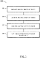
FIG. 5 is a flow diagram illustrating a method or process of extrusion additive manufacturing for veneer applications, in accordance with one or more embodiments of the disclosure; -
FIG. 6A illustrates a veneer log fabricated from sheets of veneer, the sheets of veneer fabricated via extrusion additive manufacturing, in accordance with one or more embodiments of the disclosure; -
FIG. 6B illustrates a portion of a veneer log fabricated from sheets of veneer, the sheets of veneer fabricated via extrusion additive manufacturing, in accordance with one or more embodiments of the disclosure; -
FIG. 7A illustrates a veneer log fabricated from sheets of veneer, the sheets of veneer fabricated via extrusion additive manufacturing, in accordance with one or more embodiments of the disclosure; -
FIG. 7B illustrates a portion of a veneer log fabricated from sheets of veneer, the sheets of veneer fabricated via extrusion additive manufacturing, in accordance with one or more embodiments of the disclosure; and -
FIG. 8 illustrates an extrusion additive manufacturing system for veneer applications, in accordance with one or more embodiments of the disclosure. - Reference will now be made in detail to the subject matter disclosed, which is illustrated in the accompanying drawings.
- Before explaining one or more embodiments of the disclosure in detail, it is to be understood that the embodiments are not limited in their application to the details of construction and the arrangement of the components or steps or methodologies set forth in the following description or illustrated in the drawings. In the following detailed description of embodiments, numerous specific details may be set forth in order to provide a more thorough understanding of the disclosure. However, it will be apparent to one of ordinary skill in the art having the benefit of the instant disclosure that the embodiments disclosed herein may be practiced without some of these specific details. In other instances, well-known features may not be described in detail to avoid unnecessarily complicating the instant disclosure.
- As used herein a letter following a reference numeral is intended to reference an embodiment of the feature or element that may be similar, but not necessarily identical, to a previously described element or feature bearing the same reference numeral (e.g., 1, 1a, 1b). Such shorthand notations are used for purposes of convenience only and should not be construed to limit the disclosure in any way unless expressly stated to the contrary.
- Further, unless expressly stated to the contrary, "or" refers to an inclusive or and not to an exclusive or. For example, a condition A or B is satisfied by anyone of the following: A is true (or present) and B is false (or not present), A is false (or not present) and B is true (or present), and both A and B are true (or present).
- In addition, use of "a" or "an" may be employed to describe elements and components of embodiments disclosed herein. This is done merely for convenience and "a" and "an" are intended to include "one" or "at least one," and the singular also includes the plural unless it is obvious that it is meant otherwise.
- Finally, as used herein any reference to "one embodiment" or "some embodiments" means that a particular element, feature, structure, or characteristic described in connection with the embodiment is included in at least one embodiment disclosed herein. The appearances of the phrase "in some embodiments" in various places in the specification are not necessarily all referring to the same embodiment, and embodiments may include one or more of the features expressly described or inherently present herein, or any combination of sub-combination of two or more such features, along with any other features which may not necessarily be expressly described or inherently present in the instant disclosure.
-
FIGS. 1A-8 generally illustrate extrusion additive manufacturing for veneer applications, in accordance with one or more embodiments of the disclosure. - With natural veneer, lumber may be cut from trees of the same species or different species. However, the trees may be located in numerous places around the world, which may result in variances of color, design, grain width, and/or grain pattern within the lumber. In some cases, only one log out of thousands may meet industry requirements, meaning the use of the particular veneer for installed panels and/or spare panels may be largely limited to an amount of square footage the log provides.
- With composite veneer, a tree may be broken down and meshed into a block with the addition of color. Current methods of generating composite veneer, while more likely to match across different sources than natural veneer, may be cost-prohibitive in terms of long lead time and/or the size of the bulk order that may be required.
- As such, it would be beneficial to use extrusion additive manufacturing for veneer applications to produce fabricated veneer from natural veneer, the fabricated veneer including matching color, design, grain width, and grain pattern. The fabricated veneer may address or offset the possibility of variances within the natural veneer. The fabricated veneer may be cut to custom size in a more cost-effective manner than the composite veneer.
-
FIGS. 1A-1C are flow diagrams illustrating methods or processes of extrusion additive manufacturing for veneer applications, in accordance with one or more embodiments of the disclosure.FIGS. 2A and 2B illustrate anextruder 200 for extrusion additive manufacturing for veneer applications, in accordance with one or more embodiments of the disclosure. -
FIG. 1A is a flow diagram illustrating a method orprocess 100 of extrusion additive manufacturing for veneer applications, in accordance with one or more embodiments of the disclosure. - In a
step 102, material is loaded into one or more hoppers of an extruder. Theextruder 200 may include one ormore hoppers 202. - At least some of the one or
more hoppers 202 may be filled with a raw wood material. For example, the raw wood material may include, but is not limited to, sawdust, wood shavings, wood pulp, or other wood product. By way of another example, where there aremultiple hoppers 202 filled with a wood material, eachhopper 202 may include wood material from the same source. By way of another example, where there aremultiple hoppers 202 filled with a wood material, eachhopper 202 may include wood material from different sources. For instance, eachhopper 202 may include wood material from a different species of tree. In addition, eachhopper 202 may include wood material from the different batches of the same species of tree. - At least some of the one or
more hoppers 202 may be filled with a binder (or binding agent). The binder may include, but is not limited to, a thermoplastic, an adhesive, and/or water. The adhesive may include, but is not limited to, an epoxy resin, a wood glue, or other adhesive suitable for use with wood. For example, the epoxy resin may include a clear epoxy resin that is not visible in the stack of lumber once dry. For instance, the use of an epoxy resin may allow for the color of the sheets of veneer to be replicated throughout the stack of lumber, without concern of unwanted color (e.g., a white or yellow layer). By way of another example, the epoxy resin may be a two-part epoxy resin. It is noted herein the adhesive may be in a powder, particle, and/or particulate form to mix with the wood product. - At least some of the one or
more hoppers 202 may be filled with a material selected to generate a particular color, design, grain width, and/or grain pattern. For example, the material may include a dyed water-based material. By way of another example, the material may include a thermal-sensitive material. The thermal-sensitive material may be configured to activate (e.g., in the presence of heat) and generate a particular color, design, grain width, and/or grain pattern. The thermal-sensitive material may be in a powder, particle, and/or particulate form to mix with the wood product. - At least some of the one or
more hoppers 202 may be filled with a fire-resistant and/or fire-retardant material. For example, the fire-resistant and/or fire-retardant material may include, but is not limited to, metal powder, metal particles, metal shavings, or other metal product. By way of another example, the fire-resistant and/or fire-retardant material may include, but is not limited to, a concrete, a silicate (e.g., a material with a chemical compound including SiO2 structures), or another material with one or more fire-resistant and/or fire-retardant properties. - At least some of the one or
more hoppers 202 may be filled with a removable support material configured to support a three-dimensional structure being fabricated (e.g., where gravity would cause the three-dimensional structure to break prior to completion). For example, the removable support material may be a dissolvable plastic including, but not limited to, polyvinyl alcohol (PVA), high-impact polystyrene (HIPS), or the like. By way of another example, the removable support material may be a breakway support material. - In a
step 104, a mixture may be generated from material in the one or more hoppers of the extruder. Theextruder 200 may include a chamber coupled to agantry 206 or integrated within the gantry 206 (e.g., a member of thegantry 206 includes a hollow portion). The one ormore hoppers 202 may deposit material into the chamber. The chamber may be configured to feed one ormore nozzles 204. For example, the chamber may include a screw assembly coupled to agantry 206, and the screw assembly may provide material received from the one ormore hoppers 202 to anozzle 204 of the one ormore nozzles 204. By way of another example, the chamber may feed anozzle 204 of the one ormore nozzles 204 via gravity-feed. It is noted herein, however, that ahopper 202 may be directly coupled to (and directly feed) a nozzle 204 (e.g., where thehopper 202 holds a removable support material not intended to be a part of the mixture). - The composition of the mixture may be controlled via one or more operational parameters of the one or
more nozzles 204. The one or more operational parameters (e.g., temperature, flow rate, and/or spray hole diameter) of the one ormore nozzles 204 may be independently selected and/or controlled (e.g., via one or more manufacturing processes during fabrication of the one ormore nozzles 204, manual controls during use of the one ormore nozzles 204, and/or electronic controls during use of the one or more nozzles 204). It is noted herein, however, that the selection and/or control of the one or more operational parameters may be dependent on other system control parameters (e.g., parameters of other components of theextruder 200, such as gantry track speed along an axis, fabricating surface speed along an axis, or the like). - In a
step 106, a veneer product may be fabricated via the extruder. Theextruder 200 may include aplatform 208 on a plane (e.g., an xy-plane) and a workingsurface 210 configured to translate along an axis (e.g., the y-axis). The workingsurface 210 may lead to a set ofrollers 212. For example, the set ofrollers 212 may be independent from the workingsurface 210. By way of another example, the set ofrollers 212 may be a standalone unit separate from theextruder 200. It is noted herein, however, that the workingsurface 210 may translate with the assistance of the set ofrollers 212. - The
gantry 206 of theextruder 200 may be configured to translate the one ormore nozzles 204 along a first axis (e.g., the x-axis) and/or a second axis (e.g., the z-axis) while the one ormore nozzles 204 deposit material from the one ormore hoppers 202 to form aveneer product 214. The workingsurface 210 of theextruder 200 may be configured to translate along a first axis (e.g., a y-axis) while the one ormore nozzles 204 deposit material from the one ormore hoppers 202 to form theveneer product 214. The material may be deposited to generate a particular color, design, grain pattern, and/or grain width for theveneer product 214. - As illustrated in
FIG. 2A , theveneer product 214 may include one or more sheets ofveneer 214, each sheet ofveneer 214 having a single layer.FIG. 1B is a flow diagram illustrating sub-steps of thestep 106 of the method orprocess 100 of extrusion additive manufacturing for veneer applications to fabricate theveneer product 214 inFIG. 2A , in accordance with one or more embodiments of the disclosure. - In a
step 110, a first portion of a mixture of material may be deposited on a working surface of an extruder. The one ormore nozzles 204 may travel along the x-axis to deposit the first portion of the mixture of material to generate a particular color, design, grain pattern, and/or grain width for theveneer product 214. - In a
step 112, the working surface may be actuated. The workingsurface 210 may translate along the y-axis, and the one ormore nozzles 204 may reset (e.g., lower) to the workingsurface 210. - In a
step 114, an additional portion of the mixture may be deposited proximate to the first portion of the mixture. The one ormore nozzles 204 may travel along the x-axis to deposit the additional portion of the mixture of material to generate the particular color, design, grain pattern, and/or grain width for theveneer product 214. With the actuating of the workingsurface 210, the one ormore nozzles 204 may make multiple passes when travelling along the x-axis to generate the particular color, design, grain pattern, and/or grain width for theveneer product 214. - In a
step 116, the mixture may be cured to form a veneer product. The mixture may be applied to the working surface at an increased temperature, such that the mixture may cure as it cools to form the veneer product. The mixture may be applied at or below a room operating temperature, and the binder may be activated (e.g., via heat, pressure, a combination of heat and pressure, a chemical reaction, or the like) to bind the portions deposited on the working surface prior to the mixture curing as it cools to form the veneer product. - As illustrated in
FIG. 2B , theveneer product 214 may include a three-dimensional structure 214 including multiple layers of veneer.FIG. 1C is a flow diagram illustrating sub-steps of thestep 106 of the method orprocess 100 of extrusion additive manufacturing for veneer applications to fabricate theveneer product 214 inFIG. 2B , in accordance with one or more embodiments of the disclosure. - In a
step 120, a first layer of a mixture of material is deposited on a working surface of an extruder. The one ormore nozzles 204 may travel along the x-axis to deposit the first layer of the mixture of material to generate a particular color, design, grain pattern, and/or grain width for theveneer product 214. - In a
step 122, a nozzle of the extruder is actuated. The one ormore nozzles 204 may be actuated (e.g., raised or lowered) along the z-axis to prepare to deposit an additional layer of material to generate a particular color, design, grain pattern, and/or grain width for theveneer product 214. - In a
step 124, an additional layer of the mixture is deposited on the first layer of the mixture. The one ormore nozzles 204 may travel along the x-axis to deposit the additional layer of the mixture of material to generate the particular color, design, grain pattern, and/or grain width for theveneer product 214. With the actuating of the one ormore nozzles 204, the one ormore nozzles 204 may make multiple passes when travelling along the z-axis to generate the particular color, design, grain pattern, and/or grain width for theveneer product 214. - In an
optional step 126, the working surface is actuated. The workingsurface 210 may translate along the y-axis so that the one ormore nozzles 204 may reset (e.g., lower) to the workingsurface 210. Thesteps - In a
step 128, the mixture may be cured to form a veneer product. The mixture may be applied to the working surface at an increased temperature, such that the mixture may cure as it cools to form the veneer product. The mixture may be applied at or below a room operating temperature, and the binder may be activated (e.g., via heat, pressure, a combination of heat and pressure, a chemical reaction, or the like) to bind the portions deposited on the working surface prior to the mixture curing as it cools to form the veneer product. - In this regard, the motion of the components of the extruder 200 (e.g., along the x-axis, y-axis, and/or z-axis) may allow the
extruder 200 to act as an additive manufacturing device for veneer applications, being able to form veneer having a single layer (e.g., one or more sheets) or multiple layers (e.g., a three-dimensional structure). - In a step to the
process 100, the veneer product may be firetreated. For example, theveneer product 214 may be treated with a fire-resistant and/or fire-retardant material. By way of another example, theveneer product 214 may be treated with fire. Where theveneer product 214 is a single sheet of veneer or a three-dimensional structure, theveneer product 214 may be firetreated as a single component. Where theveneer product 214 includes multiple sheets of veneer, each sheet of veneer may be firetreated individually, in batches, or in bulk. It is noted herein, however, that where the generated mixture used to fabricate aveneer product 214 includes a heat-sensitive compound such as a thermoplastic, that firetreating may alter (e.g., re-melt, re-cure, or the like) the heat-sensitive compound. - In a step of the
process 100, a coating may be applied to theveneer product 214. For example, the coating may include an infiltrant, a sealant, or other coating configured to protect theveneer product 214. For instance, the infiltrant may include an adhesive configured to fill in pores, gaps, cracks, or other imperfections that may reduce a strength of theveneer product 214. -
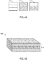
FIG. 3 is a flow diagram illustrating a method orprocess 300 of extrusion additive manufacturing for veneer applications, in accordance with one or more embodiments of the disclosure.FIG. 4A illustrates sheets of veneer fabricated via extrusion additive manufacturing, in accordance with one or more embodiments of the disclosure.FIG. 4B illustrates a veneer block or core generated from sheets of veneer fabricated via extrusion additive manufacturing, in accordance with one or more embodiments of the disclosure. - In a
step 302, multiple sheets of veneer are fabricated. The multiple sheets ofveneer 214 may be fabricated with one or more steps of theprocess 100, above. At least some of the multiple sheets of veneer may include a similar color, design, grain pattern, and/or grain width. At least some of the multiple sheets of veneer may include a different color, design, grain pattern, and/or grain width. - In a
step 304, the multiple sheets of veneer are layered. The multiple sheets ofveneer 214 may be layered to produce astack 400 of sheets of veneer 214 (e.g., a three-dimensional structure 214 including multiple layers of veneer), thestack 400 having a particular color, design, grain pattern, and/or grain width across the layered multiple sheets of veneer. For example, the multiple sheets ofveneer 214 may be layered in any order to generate the particular color, design, grain pattern, and/or grain width. For instance, as illustrated inFIG. 4B , multiple sheets ofveneer 214 with different colors, designs, grain patterns, and/or grain widths may be layered to create thestack 400 with the particular color, design, grain pattern, and/or grain width. In addition, multiple sheets ofveneer 214 with a similar color, design, grain pattern, and/or grain width may be layered to create thestack 400 with the particular color, design, grain pattern, and/or grain width. Generally, the multiple sheets ofveneer 214 may be layered in any order (e.g., without regard to the order of fabrication) in order to create thestack 400 with the particular color, design, grain pattern, and/or grain width. - In a
step 306, the multiple sheets of veneer are bound together. The binding may occur with the addition of a binder within thestack 400. For example, the binder may be the thermoplastic material included in the mixture used to fabricate the multiple sheets ofveneer 214. For instance, increasing the temperature of the stack 400 (e.g., through external application of heat, through application of pressure, or a combination of heat and pressure) may cause the thermoplastic material to melt or fuse together to form thestack 400. By way of another example, a layer of adhesive may be placed between the layers of the multiple sheets ofveneer 214, which may bind the layers of sheets ofveneer 214 together to form thestack 400. The adhesive may include, but is not limited to, an epoxy resin, a wood glue, or other adhesive suitable for use with wood. For example, the epoxy resin may include a clear epoxy resin that is not visible in the stack of lumber once dry. For instance, the use of an epoxy resin may allow for the color of the sheets of veneer to be replicated throughout the stack of lumber, without concern of unwanted color (e.g., a white or yellow layer). By way of another example, the epoxy resin may be a two-part epoxy resin. - In a
step 308, the multiple sheets of veneer are cut into a block or core. Thestack 400 may be positioned in any orientation when the block or core is cut out. For example, the block or core may be cut from any face or surface of thestack 400. By way of another example, the block or core may be cut at any angle within any face or surface of thestack 400. -
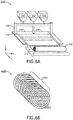
FIG. 5 is a flow diagram illustrating a method orprocess 500 of extrusion additive manufacturing for veneer applications, in accordance with one or more embodiments of the disclosure.FIGS. 6A and 6B generally illustrate a veneer log being fabricated from sheets of veneer, the sheets of veneer fabricated via extrusion additive manufacturing, in accordance with one or more embodiments of the disclosure.FIG. 7A and 7B generally illustrate a veneer log being fabricated from sheets of veneer, the sheets of veneer fabricated via extrusion additive manufacturing, in accordance with one or more embodiments of the disclosure. - In a
step 502, one or more sheets of veneer are fabricated. The one or more sheets ofveneer 214 may be fabricated with one or more steps of theprocess 100, above. At least some of the one or more sheets of veneer may include a similar color, design, grain pattern, and/or grain width. At least some of the one or more sheets of veneer may include a different color, design, grain pattern, and/or grain width. - In a
step 504, the one or more sheets of veneer are rolled into a log. The log may be fabricated from one or multiple sheets ofveneer 214. For example, in the case of multiple sheets ofveneer 214, the multiple sheets ofveneer 214 may include a similar color, design, grain pattern, and/or grain width. By way of another example, in the case of multiple sheets ofveneer 214, the multiple sheets ofveneer 214 may include different colors, designs, grain patterns, and/or grain widths. - In one example, as illustrated in
FIG. 6A , alog 600 including a particular color, design, grain pattern, and/or grain width may be fabricated from a single piece ofveneer 214. The single piece ofveneer 214 may be fabricated from theextruder 200 with the assistance of the workingsurface 210 configured to translate along an axis (e.g., the y-axis) and/or the set ofrollers 212. It is noted herein, however, that thelog 600 may be rolled from multiple sheets of veneer fed either sequentially or in a stack, where the multiple sheets ofveneer 214 include a similar color, design, grain pattern, and/or grain width. - In another example, as illustrated in
FIG. 7A , alog 700 including a particular color, design, grain pattern, and/or grain width may be fabricated from multiple pieces ofveneer 214, where at least some of the multiple pieces ofveneers 214 include a different color, design, grain pattern, and/or grain width. The multiple pieces ofveneer 214 may be fabricated from theextruder 200 with the assistance of the workingsurface 210 configured to translate along an axis (e.g., the y-axis) and/or the set ofrollers 212. The multiple sheets ofveneer 214 may be fed either sequentially or in a stack. - In an
optional step 506, the one or more sheets of veneer are bound together. The binding may occur with the addition of a binder within thelog veneer 214. For instance, increasing the temperature of thelog 600, 700 (e.g., through external application of heat, through application of pressure, or a combination of heat and pressure) may cause the thermoplastic material to melt or fuse together to form thelog veneer 214, while the one or more sheets ofveneer 214 are rolled into thelog veneer 214 together to form thelog - It is noted herein the
step 506 may be considered optional as the one or more sheets ofveneer 214 may only be temporarily kept within thelog log veneer 214 for use with another fabricating device requiring rolls of veneer as a source material. In this regard, it may not be desirable to bind the one or more sheets ofveneer 214 forming thelog - In a
step 508, the log may be cut into one or more slices. One or more slices may be cut from a working surface of the log. For example, a plane of the working surface of the log may be orthogonal to a long axis of the log (e.g., is an end surface). The one or more slices may be of a select thickness. For example, the one or more slices may be of a thickness selected for a sheet of veneer. By way of another example, the one or more slides may be of a thickness selected for a veneer block or core. - As illustrated in
FIG. 6B , one ormore slices 600a may be cut from thelog 600. As illustrated inFIG. 7B , one ormore slices 700a may be cut from thelog 700. The cut face of the one ormore slices slices slice slice - Although embodiments of the disclosure illustrate the
log slices log log log 600, 700 (e.g., an end surface, or the like). Generally, however, any surface of thelog log - It is noted herein the
processes processes processes processes - In this regard, a veneer with a selected color, design, grain width, and/or grain pattern may be digitally designed without being reliant upon natural resources and/or a limited supply. The veneer may recreate a color, design, grain width, and/or grain pattern based on a veneer selected or provided by a user (e.g., a consumer, manufacturer, or other individual involved with the selection of the veneer being sequenced). The veneer may be repeatably fabricated to ensure a consistency of a component aesthetic mass-produced for, disseminated for, and/or installed within a vehicle (e.g., an aircraft, an automobile, or the like). The ability to repeatably fabricate the veneer may allow for the repair and/or replacement of an original product with an exact duplicate of the original product. The ability to repeatably fabricate the veneer may result in bulk production, production on demand, the ability to maintain a digital inventory, and/or potential cost savings (e.g., in the form of material collection and use, or the like).
-
FIG. 8 illustrates asystem 800 used for extrusion additive manufacturing for veneer applications, in accordance with one or more embodiments of the present disclosure. - A set of data 802 may be transmitted through the
system 800. The set of data 802 may include data defining a particular color, design, grain pattern, and/or grain width for veneer. The set of data 802 may be received from auser 804. For example, theuser 804 may include a consumer, a manufacturer, or other individual involved with the selection of the veneer being sequenced. It is noted herein the set of data 802 may be received by the one ormore controllers 808 either directly or indirectly (e.g., through an intermediary, where the consumer passes the set of data 802 to the manufacturer and the manufacturer uploads the data). - The set of data 802 may be received from a
scanning tool 806. For example, where the veneer needs to match a previously-used and/or installed veneer in a vehicle (e.g., airplane, automobile, or the like), the color, design, grain width, and/or grain pattern may be scanned with ascanning tool 806 to generate the set of data 802. - The set of data 802 may be received by one or
more controllers 808. The one ormore controllers 808 may include may include at least one of one ormore processors 810,memory 812 configured to store one or more sets ofprogram instructions 814, and/or one or more communication interfaces 816. - The one or
more processors 810 provides processing functionality for at least the one ormore controllers 808 and may include any number of processors, micro-controllers, circuitry, field programmable gate array (FPGA) or other processing systems, and resident or external memory for storing data, executable code, and other information accessed or generated by the one ormore controllers 808. The one ormore processors 810 may execute one or more software programs (e.g., the one or more sets of program instructions 814) embodied in a non-transitory computer readable medium (e.g., the memory 812) that implement techniques described herein. The one ormore processors 810 are not limited by the materials from which it is formed or the processing mechanisms employed therein and, as such, may be implemented via semiconductor(s) and/or transistors (e.g., using electronic integrated circuit (IC) components), and so forth. - The
memory 812 may be an example of tangible, computer-readable storage medium that provides storage functionality to store various data and/or program code associated with operation of the one ormore controllers 808 and/or one ormore processors 810, such as software programs and/or code segments, or other data to instruct the one ormore processors 810 and/or other components of the one ormore controllers 808, to perform the functionality described herein. Thus, thememory 812 may store data, such as a program of instructions for operating the one ormore controllers 808, including its components (e.g., one ormore processors 810, the one ormore communication interfaces 816, or the like), and so forth. It should be noted that while asingle memory 812 is described, a wide variety of types and combinations of memory (e.g., tangible, non-transitory memory) may be employed. Thememory 812 may be integral with the one ormore processors 810, may include stand-alone memory, or may be a combination of both. Some examples of thememory 812 may include removable and non-removable memory components, such as random-access memory (RAM), read-only memory (ROM), flash memory (e.g., a secure digital (SD) memory card, a mini-SD memory card, and/or a micro-SD memory card), solid-state drive (SSD) memory, magnetic memory, optical memory, universal serial bus (USB) memory devices, hard disk memory, external memory, and so forth. - The one or
more controllers 808 may be configured to perform one or more process steps, as defined by the one or more sets ofprogram instructions 814. The one or more process steps may be performed iteratively, concurrently, and/or sequentially. The one or more sets ofprogram instructions 814 may be configured to operate via a control algorithm, a neural network (e.g., with states represented as nodes and hidden nodes and transitioning between them until an output is reached via branch metrics), a kernel-based classification method, a Support Vector Machine (SVM) approach, canonical-correlation analysis (CCA), factor analysis, flexible discriminant analysis (FDA), principal component analysis (PCA), multidimensional scaling (MDS), principal component regression (PCR), projection pursuit, data mining, prediction-making, exploratory data analysis, supervised learning analysis, boolean logic (e.g., resulting in an output of a complete truth or complete false value), fuzzy logic (e.g., resulting in an output of one or more partial truth values instead of a complete truth or complete false value), or the like. For example, in the case of a control algorithm, the one or more sets ofprogram instructions 814 may be configured to operate via proportional control, feedback control, feedforward control, integral control, proportional-derivative (PD) control, proportional-integral (PI) control, proportional-integral-derivative (PID) control, or the like. - The one or
more communication interfaces 816 may be operatively configured to communicate with components of the one ormore controllers 808. For example, the one ormore communication interfaces 816 may be configured to retrieve data from the one ormore processors 810 or other devices, transmit data for storage in thememory 812, retrieve data from storage in thememory 812, and so forth. The one ormore communication interfaces 816 may also be coupled (e.g., physically, electrically, and/or communicatively) with the one ormore processors 810 to facilitate data transfer between components of the one ormore controllers 808 and the one ormore processors 810. It should be noted that while the one ormore communication interfaces 816 is described as a component of the one ormore controllers 808, one or more components of the one ormore communication interfaces 816 may be implemented as external components coupled (e.g., physically, electrically, and/or communicatively) to the one ormore controllers 808 via a wired and/or wireless connection. The one ormore controllers 808 may also include and/or connect to one or more input/output (I/O) devices. In some embodiments, the one ormore communication interfaces 816 includes or is coupled (e.g., physically, electrically, and/or communicatively) to a transmitter, receiver, transceiver, physical connection interface, or any combination thereof. - The one or
more controllers 808 may be coupled (e.g., physically, electrically, and/or communicatively) to one ormore user interfaces 818. The one ormore user interfaces 818 may include and/or be configured to interact with one ormore display devices 820. The one ormore user interfaces 818 may include and/or be configured to interact with one or moreuser input devices 822. - The one or
more communication interfaces 816 may be operatively configured to communicate with one ormore user interfaces 818. The one ormore controllers 808 and the one ormore user interfaces 818 may be separate components (e.g., have separate housings and/or separate chassis). It is noted herein, however, that the one ormore controllers 808 and the one ormore user interfaces 818 may be components integrated in a single housing and/or on a single chassis. - The one or
more display devices 820 may include any display device known in the art. For example, the one ormore display devices 820 may include, but are not limited to, a liquid crystal display (LCD), a light-emitting diode (LED) display, an organic light-emitting diode (OLED) based display, or the like. Those skilled in the art should recognize that a variety ofdisplay devices 820 may be suitable for implementation in the disclosure and the particular choice of display device may depend on a variety of factors, including, but not limited to, form factor, cost, and the like. In a general sense, any display device capable of integration with the one or more user input devices 822 (e.g., touchscreen, bezel mounted interface, keyboard, mouse, trackpad, and the like) is suitable for implementation in the disclosure. - The one or more
user input devices 822 may include any data input device known in the art. For example, the one or moreuser input devices 822 may include, but are not limited to, a keyboard, a keypad, a touchscreen, a lever, a knob, a scroll wheel, a track ball, a switch, a dial, a sliding bar, a scroll bar, a slide, a touch pad, a paddle, a steering wheel, a joystick, a button, a bezel input device or the like. In the case of a touchscreen interface, those skilled in the art should recognize that a large number of touchscreen interfaces may be suitable for implementation in the disclosure. For instance, a display device may be integrated with a touchscreen interface, such as, but not limited to, a capacitive touchscreen, a resistive touchscreen, a surface acoustic based touchscreen, an infrared based touchscreen, or the like. In a general sense, any touchscreen interface capable of integration with the display portion of a display device is suitable for implementation in the disclosure. - The one or
more communication interfaces 816 may be operatively configured to communicate with components of thescanning tool 806. - The one or
more communication interfaces 816 may be operatively coupled (e.g., physically, electrically, and/or communicatively) with components of theextruder 200. For example, the one ormore controllers 808 may be configured to adjust one or moreoperational parameters 824 for theextruder 200. For instance, the one or moreoperational parameters 824 may include operational parameters for the one or more nozzles 204 (e.g., temperature, flow rate, and/or spray hole diameter), the one or more hoppers 202 (e.g., feed rate of a particular material within a particular hopper 202), the gantry 206 (e.g., translation in a direction along the x-axis or the z-axis, as illustrated inFIGS. 2A ,6A , and7A ), the working surface 210 (e.g., translation in a direction along the y-axis, as illustrated inFIGS. 2A ,6A , and7A ), or the like. - Although embodiments of the present disclosure illustrate the one or
more controllers 808 as adjusting the one or moreoperational parameters 824 of theextruder 200, it is noted herein the one or more operational parameters may be adjusted via manual controls ormanual instructions 826 from theuser 804. Therefore, the description should not be interpreted as a limitation on the scope of the disclosure but merely an illustration. - Although inventive concepts have been described with reference to the embodiments illustrated in the attached drawing figures, equivalents may be employed and substitutions made herein without departing from the scope of the claims. Components illustrated and described herein are merely examples of a system/device and components that may be used to implement embodiments of the inventive concepts and may be replaced with other devices and components without departing from the scope of the claims. Furthermore, any dimensions, degrees, and/or numerical ranges provided herein are to be understood as nonlimiting examples unless otherwise specified in the claims.
Claims (15)
- A method of extrusion additive manufacturing for veneer applications, comprising:loading material into an extruder (200), the material including wood product and a binder;generating a mixture from the material; andfabricating a veneer product (214) by:depositing a first portion of the mixture on a working surface of the extruder;actuating the working surface; anddepositing an additional portion of the mixture on the working surface (210) of the extruder proximate to the first position of the mixture deposited on the working surface.
- The method of Claim 1, the first portion and the additional portion of the mixture being deposited as part of a first layer of the veneer product, the method further comprising:actuating a nozzle (204) of the extruder; anddepositing an additional layer of the mixture on the first layer.
- The method of Claim 2, further comprising:
curing the mixture to form the veneer product. - The method of Claim 1, 2 or 3, the veneer product (214) including a three-dimensional structure, the three-dimensional structure being formed from at least the first layer of deposited mixture and the additional layer of deposited mixture.
- The method of any preceding Claim, the veneer product including a plurality of sheets of veneer, the method further comprising:layering the plurality of sheets of veneer; andcutting the plurality of sheets of veneer into a block.
- The method of Claim 5, the method further comprising:
binding the plurality of sheets of veneer prior to cutting the plurality of sheets of veneer into the block. - The method of any of Claims 1 to 4, the veneer product including one or more sheets of veneer, the method further comprising:
rolling the one or more sheets of veneer into a log. - The method of Claim 7, the method further comprising:
binding the one or more sheets of veneer after rolling the one or more sheets of veneer into the log. - The method of Claim 8, the method further comprising:
cutting the log into one or more slices. - The method of any preceding Claim, the binder being a thermoplastic.
- The method of any of Claims 1 to 9, the binder being an adhesive.
- The method of any preceding Claim, the material further including at least one of a fire-retardant or a fire-resistant material.
- The method of Claim 12, the material further including a metal.
- A method of extrusion additive manufacturing for veneer applications, comprising:loading material into an extruder, the material including wood product and a binder;generating a mixture from the material; andfabricating a veneer product by:depositing a first layer of the mixture on a working surface of the extruder;actuating a nozzle of the extruder; anddepositing an additional layer of the mixture on the first layer of the mixture.
- The method of Claim 14, the first layer and the additional layer being deposited from a first portion of the mixture, the method further comprising:actuating the working surface; anddepositing an additional portion of the mixture on the working surface of the extruder proximate to the first position of the mixture deposited on the working surface.
Applications Claiming Priority (1)
| Application Number | Priority Date | Filing Date | Title |
|---|---|---|---|
| US16/716,949 US11292184B2 (en) | 2019-12-17 | 2019-12-17 | Extrusion additive manufacturing for veneer applications |
Publications (2)
| Publication Number | Publication Date |
|---|---|
| EP3848171A2 true EP3848171A2 (en) | 2021-07-14 |
| EP3848171A3 EP3848171A3 (en) | 2021-12-01 |
Family
ID=73855455
Family Applications (1)
| Application Number | Title | Priority Date | Filing Date |
|---|---|---|---|
| EP20215189.0A Pending EP3848171A3 (en) | 2019-12-17 | 2020-12-17 | Extrusion additive manufacturing for veneer applications |
Country Status (2)
| Country | Link |
|---|---|
| US (1) | US11292184B2 (en) |
| EP (1) | EP3848171A3 (en) |
Families Citing this family (2)
| Publication number | Priority date | Publication date | Assignee | Title |
|---|---|---|---|---|
| WO2022056386A1 (en) * | 2020-09-11 | 2022-03-17 | Impossible Objects, Inc. | Soluble support for fused deposition modeling |
| DE102022211600A1 (en) * | 2022-11-03 | 2024-05-08 | Volkswagen Aktiengesellschaft | Process arrangement for the production of a layered wooden component |
Family Cites Families (22)
| Publication number | Priority date | Publication date | Assignee | Title |
|---|---|---|---|---|
| US1022970A (en) | 1911-01-06 | 1912-04-09 | Willard J Ott | Veneer-barrel-making machine. |
| DE3200257C2 (en) | 1982-01-07 | 1986-07-10 | Matsushita Electric Works, Ltd., Kadoma, Osaka | Process for the production of artificial veneers |
| DE3416662A1 (en) * | 1983-11-05 | 1985-05-15 | Hoechst Ag, 6230 Frankfurt | FLAME-RETARDANT EXTRACT BODIES, ESPECIALLY EXTRESS PLATES, AND FLAME-RESISTANT VENEERED OR COATED EXTRACT PLATES, A METHOD FOR THEIR PRODUCTION AND THEIR USE |
| US5123465A (en) | 1988-09-19 | 1992-06-23 | Solid Percussion, Inc. | Method of making a drum shell or other such circumferential component |
| JPH0481866A (en) | 1990-07-25 | 1992-03-16 | Konica Corp | Automatic both-side copying device |
| US20080067713A1 (en) * | 2004-12-14 | 2008-03-20 | Robert Bordener | Method of producing and business model for applying a thin laminate sheet of a decorative material |
| DE102005005339A1 (en) | 2005-01-27 | 2006-08-10 | Hd Wood Technologies Ltd. | Process for veneer production |
| ITMI20081307A1 (en) | 2008-07-18 | 2010-01-19 | Tabu Spa | BLOCK AND PLANERS IN MULTILAMINAR WOOD AND METHOD FOR THEIR REALIZATION |
| CN102431065A (en) | 2011-10-25 | 2012-05-02 | 江苏快乐木业集团有限公司 | Straight grain laminated veneer lumber, processing method and application thereof |
| EP2832558B1 (en) | 2013-08-01 | 2018-12-26 | Alpi S.P.A. | Method for making a decorative multilaminar veneer |
| CN109130438B (en) * | 2014-03-31 | 2021-05-07 | 塞拉洛克创新股份有限公司 | Composite board and panel |
| DE102015201464B4 (en) | 2015-01-28 | 2016-10-20 | Brav-O-Tech Gmbh | Device and method for gluing particles |
| EP3257661B1 (en) * | 2016-06-17 | 2019-02-27 | UPM-Kymmene Corporation | A composite material for additive manufacturing of a three-dimensional composite product |
| SG10201608367PA (en) | 2016-10-05 | 2018-05-30 | Yong Leong Chang | Method and system for producing an engineered wood |
| US10603813B2 (en) * | 2016-10-17 | 2020-03-31 | Telescope Casual Furniture, Inc. | Products having a wood grain appearance, and methods and structures for use in forming same |
| EP3542011B1 (en) | 2016-11-18 | 2023-06-14 | Aectual Holding B.V. | A method for making a surface covering |
| US20180258559A1 (en) | 2017-03-10 | 2018-09-13 | University Of Tennessee Research Foundation | Materials for improved polymeric 3d printing |
| CN106976344A (en) | 2017-03-29 | 2017-07-25 | 曾华 | A kind of production method of 3D printing beaver board facing |
| NL2018728B1 (en) | 2017-04-18 | 2018-10-29 | Stephan Schuermann Holding B V | A gantry-type three dimensional printing apparatus for printing a three dimensional work piece in a layer wise manner. |
| DE102017113764B3 (en) | 2017-06-21 | 2018-11-08 | Novem Car Interior Design Gmbh | Method for producing a wood veneer, veneer block, method for producing a molded part and molded part |
| US10759114B2 (en) | 2017-12-29 | 2020-09-01 | Continuous Composites Inc. | System and print head for continuously manufacturing composite structure |
| DK3735443T3 (en) | 2018-01-07 | 2022-05-30 | Yissum Res Dev Co Of Hebrew Univ Jerusalem Ltd | WOOD PASTE AND ARTICLES MADE THEREOF |
-
2019
- 2019-12-17 US US16/716,949 patent/US11292184B2/en active Active
-
2020
- 2020-12-17 EP EP20215189.0A patent/EP3848171A3/en active Pending
Also Published As
| Publication number | Publication date |
|---|---|
| EP3848171A3 (en) | 2021-12-01 |
| US20210178671A1 (en) | 2021-06-17 |
| US11292184B2 (en) | 2022-04-05 |
Similar Documents
| Publication | Publication Date | Title |
|---|---|---|
| Diegel et al. | Curved layer fused deposition modeling in conductive polymer additive manufacturing | |
| US11292184B2 (en) | Extrusion additive manufacturing for veneer applications | |
| US10261499B2 (en) | Device and method of manufacturing customizable three-dimensional objects | |
| EP3221125B1 (en) | Generating three-dimensional objects | |
| US20180071988A1 (en) | Three-dimensional printing systems | |
| US10046547B2 (en) | Systems and methods for implementing three dimensional (3D) object, part and component manufacture including displacement/vibration welded or heat staked laminates | |
| AU2018383793A1 (en) | Three-dimensional printing and forming method for fiber reinforced resin-based composite material | |
| CN103358425B (en) | For the method manufacturing flat prepreg material blank | |
| JP6945977B2 (en) | Battery assembly, battery storage, and related manufacturing methods | |
| TWI678273B (en) | Method for fabricating an electronic component made of only dyneemar and indalloy, method for fabricating an electronic component, and electronic component | |
| EP3838559B1 (en) | Binder jetting additive manufacturing for veneer applications | |
| KR20170093431A (en) | 3D printer for multi-Extruder | |
| US11305484B2 (en) | Laminated object additive manufacturing for veneer applications | |
| CN104908316A (en) | Molding method and molding system | |
| US11097488B2 (en) | Printer having print assembly | |
| Novakova-Marcincinova et al. | Production of composite material by FDM rapid prototyping technology | |
| US20190118417A1 (en) | System, components and methodologies for additive manufactured tools for compression molding | |
| CN113329863B (en) | Apparatus, system, and method of combining additive manufacturing print types | |
| KR20250085011A (en) | The filament manufacturing apparatus for 3D printer using recycled marine plastic waste | |
| Udroiu et al. | Rapid prototyping and rapid manufacturing applications at Transilvania University of Braşov | |
| Migliore | Design and manufacturing of WAAM parts to consolidate new R+ D metal AM capabilities at CIM UPC's pilot plant | |
| Yoon et al. | 3D printing technology and its applications in the future food industry: a review | |
| GARDINER | Additive manufacturing: Can you print a car? | |
| Butuna | Fused Deposition Modeling: A Comprehensive Systematic Review of Process Capability, Limitation and Future Trends | |
| El Mesbahi et al. | Reviews of Mechanical Design and Electronic Control of Multi-material/Color FDM |
Legal Events
| Date | Code | Title | Description |
|---|---|---|---|
| PUAI | Public reference made under article 153(3) epc to a published international application that has entered the european phase |
Free format text: ORIGINAL CODE: 0009012 |
|
| STAA | Information on the status of an ep patent application or granted ep patent |
Free format text: STATUS: THE APPLICATION HAS BEEN PUBLISHED |
|
| AK | Designated contracting states |
Kind code of ref document: A2 Designated state(s): AL AT BE BG CH CY CZ DE DK EE ES FI FR GB GR HR HU IE IS IT LI LT LU LV MC MK MT NL NO PL PT RO RS SE SI SK SM TR |
|
| PUAL | Search report despatched |
Free format text: ORIGINAL CODE: 0009013 |
|
| AK | Designated contracting states |
Kind code of ref document: A3 Designated state(s): AL AT BE BG CH CY CZ DE DK EE ES FI FR GB GR HR HU IE IS IT LI LT LU LV MC MK MT NL NO PL PT RO RS SE SI SK SM TR |
|
| STAA | Information on the status of an ep patent application or granted ep patent |
Free format text: STATUS: REQUEST FOR EXAMINATION WAS MADE |
|
| 17P | Request for examination filed |
Effective date: 20220601 |
|
| RBV | Designated contracting states (corrected) |
Designated state(s): AL AT BE BG CH CY CZ DE DK EE ES FI FR GB GR HR HU IE IS IT LI LT LU LV MC MK MT NL NO PL PT RO RS SE SI SK SM TR |
|
| P01 | Opt-out of the competence of the unified patent court (upc) registered |
Effective date: 20230922 |
|
| STAA | Information on the status of an ep patent application or granted ep patent |
Free format text: STATUS: EXAMINATION IS IN PROGRESS |
|
| 17Q | First examination report despatched |
Effective date: 20250520 |