EP3848074A1 - Plunging apparatus for syringe - Google Patents
Plunging apparatus for syringe Download PDFInfo
- Publication number
- EP3848074A1 EP3848074A1 EP18932964.2A EP18932964A EP3848074A1 EP 3848074 A1 EP3848074 A1 EP 3848074A1 EP 18932964 A EP18932964 A EP 18932964A EP 3848074 A1 EP3848074 A1 EP 3848074A1
- Authority
- EP
- European Patent Office
- Prior art keywords
- threaded
- pushing
- segment
- pushing member
- resilient
- Prior art date
- Legal status (The legal status is an assumption and is not a legal conclusion. Google has not performed a legal analysis and makes no representation as to the accuracy of the status listed.)
- Granted
Links
- 239000003814 drug Substances 0.000 claims abstract description 52
- 238000002347 injection Methods 0.000 claims abstract description 36
- 239000007924 injection Substances 0.000 claims abstract description 36
- 229940079593 drug Drugs 0.000 claims description 7
- 210000000078 claw Anatomy 0.000 description 2
- 238000007599 discharging Methods 0.000 description 2
- 230000005540 biological transmission Effects 0.000 description 1
- 239000000203 mixture Substances 0.000 description 1
Images


Classifications
-
- A—HUMAN NECESSITIES
- A61—MEDICAL OR VETERINARY SCIENCE; HYGIENE
- A61M—DEVICES FOR INTRODUCING MEDIA INTO, OR ONTO, THE BODY; DEVICES FOR TRANSDUCING BODY MEDIA OR FOR TAKING MEDIA FROM THE BODY; DEVICES FOR PRODUCING OR ENDING SLEEP OR STUPOR
- A61M5/00—Devices for bringing media into the body in a subcutaneous, intra-vascular or intramuscular way; Accessories therefor, e.g. filling or cleaning devices, arm-rests
- A61M5/178—Syringes
- A61M5/31—Details
- A61M5/315—Pistons; Piston-rods; Guiding, blocking or restricting the movement of the rod or piston; Appliances on the rod for facilitating dosing ; Dosing mechanisms
- A61M5/31511—Piston or piston-rod constructions, e.g. connection of piston with piston-rod
- A61M5/31515—Connection of piston with piston rod
-
- A—HUMAN NECESSITIES
- A61—MEDICAL OR VETERINARY SCIENCE; HYGIENE
- A61M—DEVICES FOR INTRODUCING MEDIA INTO, OR ONTO, THE BODY; DEVICES FOR TRANSDUCING BODY MEDIA OR FOR TAKING MEDIA FROM THE BODY; DEVICES FOR PRODUCING OR ENDING SLEEP OR STUPOR
- A61M5/00—Devices for bringing media into the body in a subcutaneous, intra-vascular or intramuscular way; Accessories therefor, e.g. filling or cleaning devices, arm-rests
- A61M5/178—Syringes
- A61M5/31—Details
- A61M5/315—Pistons; Piston-rods; Guiding, blocking or restricting the movement of the rod or piston; Appliances on the rod for facilitating dosing ; Dosing mechanisms
- A61M5/31525—Dosing
- A61M5/31528—Dosing by means of rotational movements, e.g. screw-thread mechanisms
-
- A—HUMAN NECESSITIES
- A61—MEDICAL OR VETERINARY SCIENCE; HYGIENE
- A61M—DEVICES FOR INTRODUCING MEDIA INTO, OR ONTO, THE BODY; DEVICES FOR TRANSDUCING BODY MEDIA OR FOR TAKING MEDIA FROM THE BODY; DEVICES FOR PRODUCING OR ENDING SLEEP OR STUPOR
- A61M5/00—Devices for bringing media into the body in a subcutaneous, intra-vascular or intramuscular way; Accessories therefor, e.g. filling or cleaning devices, arm-rests
- A61M5/178—Syringes
- A61M5/31—Details
- A61M5/315—Pistons; Piston-rods; Guiding, blocking or restricting the movement of the rod or piston; Appliances on the rod for facilitating dosing ; Dosing mechanisms
- A61M5/31565—Administration mechanisms, i.e. constructional features, modes of administering a dose
- A61M5/31576—Constructional features or modes of drive mechanisms for piston rods
- A61M5/31578—Constructional features or modes of drive mechanisms for piston rods based on axial translation, i.e. components directly operatively associated and axially moved with plunger rod
-
- A—HUMAN NECESSITIES
- A61—MEDICAL OR VETERINARY SCIENCE; HYGIENE
- A61M—DEVICES FOR INTRODUCING MEDIA INTO, OR ONTO, THE BODY; DEVICES FOR TRANSDUCING BODY MEDIA OR FOR TAKING MEDIA FROM THE BODY; DEVICES FOR PRODUCING OR ENDING SLEEP OR STUPOR
- A61M5/00—Devices for bringing media into the body in a subcutaneous, intra-vascular or intramuscular way; Accessories therefor, e.g. filling or cleaning devices, arm-rests
- A61M5/178—Syringes
- A61M5/31—Details
- A61M5/315—Pistons; Piston-rods; Guiding, blocking or restricting the movement of the rod or piston; Appliances on the rod for facilitating dosing ; Dosing mechanisms
- A61M5/31511—Piston or piston-rod constructions, e.g. connection of piston with piston-rod
- A61M2005/31521—Pistons with a forward extending skirt at their front end
Definitions
- the present invention relates to a syringe, and more particularly to a plunging apparatus for a syringe, wherein when the plunging apparatus is connected with a medication vial containing medicine inside, a pushing rod of a rotating driving mechanism can be moved automatically to a starting position where the pushing rod abuts against a piston in the medication vial.
- a conventional injection device includes two types, wherein one type is quantitative type and the other is time-metering type.
- a conventional injection device of the quantitative type after the injection device is connected with a medication vial, a pushing rod mounted on a rear end of the injection device is pushed. Consequently, a piston in the medication vial is pushed to move for a predetermined distance with the transmission of a driving assembly of the injection device.
- the driving assembly of the conventional injection device has a composition of a large screw travel and a small screw travel to transfer a straight force provided by a user pushing the pushing rod of the injection device to a rotation force. With the rotation force of the large screw travel being transferred to the pushing force for injection medicine provided by the small screw travel, a fixed amount of medication can be injected and the injection device is laborsaving in operation.
- the main objective of the invention is to provide a plunging apparatus for a syringe to solve the problem of inconvenience caused by that the user has to manually rotate the driving assembly to discharge the air.
- this invention provides a plunging apparatus for a syringe, disposed in a threaded driving mechanism of a syringe, and connected with a medication vial, characterized in that the plunging apparatus comprises:
- connection element includes two resilient hooks spaced at even angular intervals;
- pushing rod includes two holes defined in the front segment and corresponding respectively to the two resilient hooks in position; and
- the ejection element includes two engagement hooks engaged respectively with the two holes.
- connection element has two engagement portions formed on a rear side of the connection base; the two engagement portions and the two resilient hooks are arranged in an alternative manner; each engagement portion has an engaging hole defined in the engagement portion; and the front segment of the pushing rod has two engaging blocks engaged respectively with the engaging holes in the two engagement portions of the connection element.
- the threaded pushing member includes two channels formed on the outer surface of the threaded pushing member and diametrically opposite each other; and the annular body of the unidirectional check element includes two ribs formed on the inner surface of the inner hole and engaged respectively with the two channels.
- the pushing rod has a rear segment formed on a rear end of the threaded segment and having at least one resilient block formed on the rear segment at a position adjacent to the threaded segment and at least one through hole formed respectively around the at least one resilient block; and each one of the at least one resilient block has a rear end connected with the rear segment and a free front end.
- the advantages of the present invention are as follows.
- the plunging apparatus in accordance with the present invention can be applied to a driving assembly of an injection device and is connected with a medicine vial, the connection element is connected with the pushing element, and the unidirectional check element is inserted into a rear opening of the medicine vial.
- the inner periphery of the rear opening will press the resilient hooks of the connection element to bend inward.
- the bent resilient hooks will press engagement hooks of the ejection element to be bent inward and to disengage from the holes in the front segment of the pushing rod so as to unlock the ejection element.
- the ejection element With the energy stored by the compressed spring, the ejection element is ejected to move forward and to push the pushing element to move forward a predetermined distance and to abut against the piston in the medicine vial.
- the medicine in the medicine vial is pressed by the forward moving piston, and the air in the front end of the medicine vial can be discharged completely via a needle. Accordingly, the medicine vial can be completely filled with medicine.
- the air can be discharged automatically but not manually. Therefore, the convenience of using the injection device can be improved.
- the pushing element can be kept from moving backward to ensure that the pushing element of the plunging apparatus can abut against the piston in the medicine vial. Accordingly, the dose of the medicine can be controlled precisely.
- a preferred embodiment of a plunging apparatus 1 for a syringe in accordance with the present invention comprises a pushing element 10, a unidirectional check element 20, a connection element 30, a pushing rod 40, an ejection element 50, a spring 60, a threaded collar 70, and an injection rod.
- the pushing element 10 comprises a threaded pushing member 11 and a pushing board 12. Two ends of the threaded pushing member 11 are defined respectively as a front end 111 and a rear end 112. A thread 110 is formed on an outer surface of the threaded pushing member 11 and is a right hand thread. At least one channel 113 is defined in the outer surface of the threaded pushing member 11. In the preferred embodiment, the threaded pushing member 11 includes two channels 113 defined in the outer surface and being diametrically opposite each other.
- the pushing board 12 is mounted on the front end 111 of the threaded pushing member 11.
- the pushing board 12 has a through hole 121 defined in a center thereof.
- the front end 111 of the threaded pushing member 11 extends into the through hole 121.
- the threaded pushing member 11 and the pushing board 12 are individual components and are combined with each other.
- the threaded pushing member 11 and the pushing board 12 can be formed as a single piece (not shown).
- the unidirectional check element 20 is mounted around the pushing element 10, and the pushing element 10 is axially moveable inside the unidirectional check element 20 and can rotate with the unidirectional check element 20.
- the unidirectional check element 20 comprises an annular body 21 and at least one unidirectional ratchet resilient tab 22.
- the annular body 21 has an inner hole 210, and at least one rib 211 is formed on and extends longitudinally on an inner surface of the inner hole 210.
- the inner hole 210 includes two ribs 211.
- the threaded pushing member 11 of the pushing element 10 is mounted in the inner hole 210 in the annular body 21, and the ribs 211 of the annular body 21 are engaged respectively with the channels 113 in the threaded pushing member 11.
- the at least one unidirectional ratchet resilient tab 22 is formed on an outer surface of the annular body 21.
- the unidirectional check element 20 includes two unidirectional ratchet resilient tabs 22, and each unidirectional ratchet resilient tab has a unidirectional ratchet claw 221.
- connection element 30 is mounted around the pushing element 10 and the unidirectional check element 20 and comprises a connection base 31 and at least one resilient hook 32.
- the connection base 31 has a unidirectional ratchet toothed recess 311 defined in the connection base 31 and having a front opening.
- a connection board is located at a rear end of the unidirectional ratchet toothed recess 311.
- the unidirectional ratchet toothed recess 311 has multiple single oblique ratchet teeth.
- a threaded hole 313 is defined in the connection board 312.
- the threaded hole 313 in the connection board 312 has a tooth width smaller than a pitch of the threaded pushing member 11 of the pushing element 10.
- the pushing board 12 of the pushing element 10 is located outside the front end of the connection element 30.
- the unidirectional check element 20 is located inside the unidirectional ratchet toothed recess 311, and the at least one unidirectional ratchet resilient tab 22 of the unidirectional check element 20 is engaged with the unidirectional ratchet toothed recess 311. Accordingly, the unidirectional check element 20 can only unidirectionally rotate in the connection element 30.
- the threaded pushing member 11 of the pushing element 10 is screwed with the threaded hole 313 in the connection board 312.
- connection element 30 includes two resilient hooks 32 spaced at even angular intervals.
- the connection element 30 has two engagement portions 33 formed on a rear side of the connection base 31, and each engagement portion 33 has an engaging hole 331 defined in the engagement portion 33. The two engagement portions 33 and the two resilient hooks 32 are arranged in an alternative manner.
- the pushing rod 40 is connected with the rear end of the connection element 30 and comprises a threaded segment 41, a front segment 42, and a rear segment 43.
- a pushing thread is formed on an outer surface of the threaded segment 41 and is a right hand thread.
- the pushing thread of the threaded segment 41 and the thread on the threaded pushing member 11 of the pushing element 11 have a same handedness.
- the front segment 42 is formed on a front end of the threaded segment 41
- the rear segment 43 is formed on a rear end of the threaded segment 41.
- a front chamber 44 provided with a front opening is formed in the front end of the pushing rod 40.
- a rear chamber 44 is defined in the pushing rod 40 at a position behind the front chamber 45 provided with a rear opening.
- An abutment board 46 is formed between the front chamber 44 and the rear chamber 45.
- the abutment board 46 of the pushing rod 40 is located inside the threaded segment 41 in a position being adjacent to the front end of the front segment 42.
- the front chamber 44 extends from the front end of the pushing rod 40 to the front end of the threaded segment 41 through the front segment 42.
- At least one hole 421 is defined radially in an outer surface of the front segment 42 and communicates with the front chamber 44.
- the front segment 42 has two holes 421, and two engaging blocks 422 are formed on an outer surface of the front segment 42. The two engaging blocks 422 on the front segment 42 of the pushing rod 40 are engaged respectively with the engaging holes 331 in the two engagement portions 33 of the connection element 30.
- the resilient hooks 32 correspond respectively to the holes 421 in the pushing rod 40 in position.
- the rear chamber 45 extends from the threaded segment 41 to the rear end of the pushing rod 40 through the rear segment 43.
- At least one resilient block 47 is formed on the rear segment 43 at a position adjacent to the threaded segment 41, and at least one through hole 48 is formed respectively around the at least one resilient block 47.
- Each engaging block 47 has a rear end connected with the rear segment 43 and a free front end.
- the ejection element 50 is mounted in the front chamber 44 of the pushing rod 40 and comprises a base board 51, at least one engagement hook 52, and an ejection stub 53.
- the at least one engagement hook 52 and the ejection stub 53 are formed on and extend forward from a front side of the base board 51.
- the ejection element 50 includes two engagement hooks 52. In an original position, the engagement hooks 52 are engaged respectively with the holes 421 in the pushing rod 40, such that the ejection element 50 is locked in the pushing rod 40.
- the ejection stub 53 is located in a central portion of the base board 51 and corresponds to the rear end 112 of the threaded pushing member 11.
- the front end of the ejection stub 53 is spaced from the rear end 112 of the threaded pushing member 12 at a spaced interval.
- a positioning flange 54 is formed on a rear side of the base board 51.
- the spring 60 is mounted compressibly in the front chamber 44 of the pushing rod 40 and has two ends abutting respectively against the base board 51 of the ejection element 50 and the abutment board 46 of the pushing rod 40. In the original position where the ejection element 50 is locked inside the front chamber 44 of the pushing rod 40, the spring 60 is compressed to store energy.
- the front end of the spring 60 is mounted around the positioning flange 54 on the rear side of the base board 51 of the ejection element 50.
- the threaded collar 70 is screwed with the pushing rod 40 and has a threaded hole 71 screwed with the threaded segment 41 of the pushing rod 40.
- the injection rod 80 is mounted in the rear chamber 45 of the pushing rod 40 and has a front end facing the abutment board 46 of the pushing rod 40.
- the plunging apparatus 1 when the plunging apparatus 1 in accordance with the present invention is in use and is connected with a quantitative type injection device, the plunging apparatus 1 is mounted in a driving assembly of the injection device.
- the driving assembly comprises a screw tube, a screw sleeve, and a threaded driving rod.
- the driving assembly may be a conventional one, and the screw tube, the screw sleeve, and the threaded driving rod are not components of this invention. Thus, the detailed structure of the driving assembly is omitted.
- the screw tube of the driving assembly is mounted in the screw sleeve, and the threaded driving rod is mounted in the screw tube and the screw sleeve and has a function of movement driven by a large screw travel.
- the plunging apparatus 1 is mounted in the driving assembly, and the threaded collar 70 is mounted in the screw tube and can be driven to rotate in a fixed position.
- the threaded collar 70 and the pushing rod 40 have a screwing structure of a small screw travel, such that the rotation force provided by the large screw travel can be transferred to a medicine-pushing force provided by the small screw travel.
- the injection rod 80 of the plunging apparatus 1 protrudes out from an end cap connected with a rear end of the driving assembly, and a user can push the end cap.
- connection element 30 connected with the pushing element 10 and the unidirectional check element 20 is inserted into a rear opening of the medicine vial 2.
- the inner periphery of the rear opening 2B will press the resilient hooks 32 of the connection element 30 to bend inward and the bent resilient hooks 32 will press engagement hooks 52 of the ejection element 50 to be bent inward and to disengage from the holes 421 in the front segment 42 of the pushing rod 40.
- the ejection element 50 is unlocked.
- the energy stored by the compressed spring 60 will provide a resilient force to eject the ejection element 50 to move forward, and the ejected ejection element 50 will push the pushing element 10 to move forward and to abut against the piston 2A in the medicine vial 2. Accordingly, the medicine inside the medicine vial 2 can be immediately injected into a person without discharging the air by manually pushing the driving assembly to push the pushing element to abut against the piston. Thus, the injection device is convenient in use.
- the injection way of the injection device is same as that of a conventional one.
- the driving assembly of the injection device can transfer a rotation force provided by a laborsaving large screw travel to a medicine-pushing force provided by a small screw travel.
- the forward moving pushing rod 40 can provide a forward pushing force to the pushing element 10 via the connection element 30, and the rear end of the threaded pushing member 11 of the pushing element is provided with the resilient force by the spring 60 and applied to the ejection element 50.
- the pushing element 10 With the engagement between the unidirectional ratchet resilient tab 22 of the unidirectional check element 20 and the unidirectional ratchet toothed recess 311 in the connection element 30, the pushing element 10 can be kept from moving backward to ensure that the pushing element 10 of the plunging apparatus can abut against the piston 2A in the medicine vial 2. Accordingly, the dose of the medicine can be controlled precisely.
- the plunging apparatus in accordance with the present invention can be applied to a driving assembly of an injection device and is connected with a medicine vial, the connection element connected with the pushing element, and the unidirectional check element is inserted into a rear opening of the medicine vial.
- the inner periphery of the rear opening will press the resilient hooks of the connection element to bend inward.
- the bent resilient hooks will press engagement hooks of the ejection element to be bent inward and to disengage from the holes in the front segment of the pushing rod so as to unlock the ejection element.
- the ejection element With the energy stored by the compressed spring, the ejection element is ejected to move forward and to push the pushing element to move forward a predetermined distance and to abut against the piston in the medicine vial.
- the medicine in the medicine vial is pressed by the forward moving piston, and the air in the front end of the medicine vial can be discharged completely via a needle. Accordingly, the medicine vial can be completely filled with medicine. After the injection device is combined with the medicine vial, the air can be discharged automatically but not manually. Therefore, the convenience of using the injection device can be improved.
- the pushing element can be kept from moving backward to ensure that the pushing element of the plunging apparatus can abut against the piston in the medicine vial. Accordingly, the dose of the medicine can be controlled precisely.
Landscapes
- Health & Medical Sciences (AREA)
- Vascular Medicine (AREA)
- Engineering & Computer Science (AREA)
- Anesthesiology (AREA)
- Biomedical Technology (AREA)
- Heart & Thoracic Surgery (AREA)
- Hematology (AREA)
- Life Sciences & Earth Sciences (AREA)
- Animal Behavior & Ethology (AREA)
- General Health & Medical Sciences (AREA)
- Public Health (AREA)
- Veterinary Medicine (AREA)
- Infusion, Injection, And Reservoir Apparatuses (AREA)
Abstract
Description
- The present invention relates to a syringe, and more particularly to a plunging apparatus for a syringe, wherein when the plunging apparatus is connected with a medication vial containing medicine inside, a pushing rod of a rotating driving mechanism can be moved automatically to a starting position where the pushing rod abuts against a piston in the medication vial.
- For safety, an injection device can only be used for pre-determined times of shots. A conventional injection device includes two types, wherein one type is quantitative type and the other is time-metering type. In a conventional injection device of the quantitative type, after the injection device is connected with a medication vial, a pushing rod mounted on a rear end of the injection device is pushed. Consequently, a piston in the medication vial is pushed to move for a predetermined distance with the transmission of a driving assembly of the injection device. To make the conventional injection device operated laborsavingly, the driving assembly of the conventional injection device has a composition of a large screw travel and a small screw travel to transfer a straight force provided by a user pushing the pushing rod of the injection device to a rotation force. With the rotation force of the large screw travel being transferred to the pushing force for injection medicine provided by the small screw travel, a fixed amount of medication can be injected and the injection device is laborsaving in operation.
- However, after the pushing device of the driving assembly of the conventional injection device is connected with the medicine vial, a spaced interval is formed between the pushing rod of the driving assembly and the piston of the medicine vial. Therefore, before injecting medicine into a person, the pushing rod of the driving assembly has to be moved to a position where the pushing rod abuts the piston in the medicine vial to discharge air in the spaced interval manually. Consequently, medicine is injected into a person by the injection device connected with the medicine vial. The action of discharging air manually causes inconvenience in operation of the conventional injection device, and the conventional injection device has to be improved.
- The main objective of the invention is to provide a plunging apparatus for a syringe to solve the problem of inconvenience caused by that the user has to manually rotate the driving assembly to discharge the air.
- To solve the problem, this invention provides a plunging apparatus for a syringe, disposed in a threaded driving mechanism of a syringe, and connected with a medication vial, characterized in that the plunging apparatus comprises:
- a pushing element comprising a threaded pushing member and a pushing board mounted on a front end of the threaded pushing member, and the pushing member having a thread formed on an outer surface of the pushing member and at least one channel defined in the outer surface of the threaded pushing member;
- a unidirectional check element mounted around the pushing element and comprising
an annular body having - an inner hole defined in the annular body, wherein the threaded pushing member extends into the inner hole of the annular body; and
- at least one rib formed on an inner surface of the inner hole and engaged respectively with the at least one channel in the threaded pushing member to allow the threaded pushing member to axially move forward and rearward relative to the unidirectional check element; and
- at least one unidirectional ratchet resilient tab formed on an outer surface of the annular body;
- a connection element mounted around the pushing element and the unidirectional check element and comprising
- a front end, wherein the pushing board of the pushing element is located outside the front end of the connection element;
- a connection base having
- a unidirectional ratchet toothed recess defined in the connection base and having a front opening, wherein the unidirectional check element is mounted in the unidirectional ratchet toothed recess and the at least one unidirectional ratchet resilient tab is engaged with the unidirectional ratchet toothed recess;
- a connection board located at a rear end of the unidirectional ratchet toothed recess; and
- a threaded hole defined in the connection board, screwed with the threaded pushing member of the pushing element, and having a tooth width smaller than a pitch of the threaded pushing member of the pushing element to form a movement interval to allow the pushing element to axially move forward and rearward in a range of the movement interval; and
- at least one resilient hook formed on a rear end of the connection base;
- a pushing rod connected with a rear end of the connection element and having
- a threaded segment having a pushing thread formed on an outer surface of the threaded segment and having a handedness same as a handedness of the thread on the threaded pushing member;
- a front segment formed on a front end of the threaded segment and having a front chamber provided with a front opening, a rear chamber provided with a rear opening, and an abutment board formed between the front chamber and the rear chamber; and
- at least one hole defined radially in an outer surface of the front segment and communicating with the front chamber, wherein the at least one resilient hook of the connection element is mounted around the front segment and corresponds respectively to the at least one hole in position;
- an ejection element mounted in the front chamber of the pushing rod and comprising
- a base board;
- at least one engagement hook formed on a front side of the base board and engaged respectively with the at least one hole; and
- an ejection stub formed on the front side of the base board, corresponding to a rear end of the threaded pushing member in position, and having a front end spaced from the rear end of the threaded pushing member;
- a spring mounted compressibly in the front chamber of the pushing rod and having two ends abutting respectively against the base board of the ejection element and the abutment board of the pushing rod;
- a threaded collar threaded with the pushing rod and having a threaded hole screwed with the threaded segment of the pushing rod; and
- an injection rod mounted in the rear chamber of the pushing rod.
- Wherein, the connection element includes two resilient hooks spaced at even angular intervals;
the pushing rod includes two holes defined in the front segment and corresponding respectively to the two resilient hooks in position; and
the ejection element includes two engagement hooks engaged respectively with the two holes. - Wherein, the connection element has two engagement portions formed on a rear side of the connection base;
the two engagement portions and the two resilient hooks are arranged in an alternative manner;
each engagement portion has an engaging hole defined in the engagement portion; and
the front segment of the pushing rod has two engaging blocks engaged respectively with the engaging holes in the two engagement portions of the connection element. - Wherein, the threaded pushing member includes two channels formed on the outer surface of the threaded pushing member and diametrically opposite each other; and
the annular body of the unidirectional check element includes two ribs formed on the inner surface of the inner hole and engaged respectively with the two channels. - Wherein, the pushing rod has a rear segment formed on a rear end of the threaded segment and having at least one resilient block formed on the rear segment at a position adjacent to the threaded segment and at least one through hole formed respectively around the at least one resilient block; and
each one of the at least one resilient block has a rear end connected with the rear segment and a free front end. - The advantages of the present invention are as follows. The plunging apparatus in accordance with the present invention can be applied to a driving assembly of an injection device and is connected with a medicine vial, the connection element is connected with the pushing element, and the unidirectional check element is inserted into a rear opening of the medicine vial. The inner periphery of the rear opening will press the resilient hooks of the connection element to bend inward. The bent resilient hooks will press engagement hooks of the ejection element to be bent inward and to disengage from the holes in the front segment of the pushing rod so as to unlock the ejection element. With the energy stored by the compressed spring, the ejection element is ejected to move forward and to push the pushing element to move forward a predetermined distance and to abut against the piston in the medicine vial. The medicine in the medicine vial is pressed by the forward moving piston, and the air in the front end of the medicine vial can be discharged completely via a needle. Accordingly, the medicine vial can be completely filled with medicine. After the injection device is combined with the medicine vial, the air can be discharged automatically but not manually. Therefore, the convenience of using the injection device can be improved.
- Furthermore, with the engagement between the unidirectional ratchet resilient tab of the unidirectional check element and the unidirectional ratchet toothed recess in the connection element, the pushing element can be kept from moving backward to ensure that the pushing element of the plunging apparatus can abut against the piston in the medicine vial. Accordingly, the dose of the medicine can be controlled precisely.
-
-
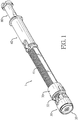
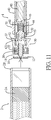
Fig. 1 is a perspective view of a preferred embodiment of a plunging apparatus for a syringe in accordance with the present invention. -
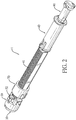
Fig. 2 is a perspective view of the plunging apparatus inFig. 1 . -
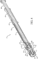
Fig. 3 is an exploded perspective view of the plunging apparatus inFig. 1 . -
Fig. 4 is a cross sectional perspective view of the plunging apparatus inFig. 1 . -
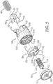
Fig. 5 is an exploded perspective view of parts of the plunging apparatus inFigs. 1 to 3 . -
Fig. 6 is another exploded perspective view of the parts of the plunging apparatus inFig. 5 . -
Fig. 7 is a cross sectional side view of the plunging apparatus inFig. 1 . -
Fig. 8 is an enlarged cross sectional side view of the plunging apparatus inFig. 7 . -
Fig. 9 is a cross sectional end view of the plunging apparatus along the line A-A inFig. 8 . -
Fig. 10 is a perspective view of the plunging apparatus inFig. 1 connected with a medicine vial. -
Fig. 11 is a first operational cross sectional side view of the plunging apparatus inFig. 1 . -
Fig. 12 is a second operational cross sectional side view of the plunging apparatus inFig. 1 . -
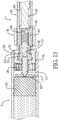
Fig. 13 is a third operational cross sectional side view of the plunging apparatus inFig. 1 . - Other objects, advantages and novel features of the invention will become more apparent from the following detailed description when taken in conjunction with the accompanying drawings.
- With reference to
Figs. 1 to 3 , a preferred embodiment of a plungingapparatus 1 for a syringe in accordance with the present invention comprises a pushingelement 10, aunidirectional check element 20, aconnection element 30, a pushingrod 40, anejection element 50, aspring 60, a threadedcollar 70, and an injection rod. - With reference to
Figs. 1 to 3 , the pushingelement 10 comprises a threaded pushingmember 11 and a pushingboard 12. Two ends of the threaded pushingmember 11 are defined respectively as afront end 111 and arear end 112. Athread 110 is formed on an outer surface of the threaded pushingmember 11 and is a right hand thread. At least onechannel 113 is defined in the outer surface of the threaded pushingmember 11. In the preferred embodiment, the threaded pushingmember 11 includes twochannels 113 defined in the outer surface and being diametrically opposite each other. The pushingboard 12 is mounted on thefront end 111 of the threaded pushingmember 11. The pushingboard 12 has a throughhole 121 defined in a center thereof. Thefront end 111 of the threaded pushingmember 11 extends into the throughhole 121. With reference toFig. 3 , the threaded pushingmember 11 and the pushingboard 12 are individual components and are combined with each other. Alternatively, the threaded pushingmember 11 and the pushingboard 12 can be formed as a single piece (not shown). - With reference to
Figs. 3 to 8 , theunidirectional check element 20 is mounted around the pushingelement 10, and the pushingelement 10 is axially moveable inside theunidirectional check element 20 and can rotate with theunidirectional check element 20. Theunidirectional check element 20 comprises anannular body 21 and at least one unidirectional ratchetresilient tab 22. Theannular body 21 has aninner hole 210, and at least onerib 211 is formed on and extends longitudinally on an inner surface of theinner hole 210. In the preferred embodiment, theinner hole 210 includes tworibs 211. The threaded pushingmember 11 of the pushingelement 10 is mounted in theinner hole 210 in theannular body 21, and theribs 211 of theannular body 21 are engaged respectively with thechannels 113 in the threaded pushingmember 11. The at least one unidirectional ratchetresilient tab 22 is formed on an outer surface of theannular body 21. In the preferred embodiment, theunidirectional check element 20 includes two unidirectional ratchetresilient tabs 22, and each unidirectional ratchet resilient tab has aunidirectional ratchet claw 221. - With reference to
Figs. 3 to 8 , theconnection element 30 is mounted around the pushingelement 10 and theunidirectional check element 20 and comprises aconnection base 31 and at least oneresilient hook 32. Theconnection base 31 has a unidirectional ratchettoothed recess 311 defined in theconnection base 31 and having a front opening. A connection board is located at a rear end of the unidirectional ratchettoothed recess 311. The unidirectional ratchettoothed recess 311 has multiple single oblique ratchet teeth. A threadedhole 313 is defined in theconnection board 312. The threadedhole 313 in theconnection board 312 has a tooth width smaller than a pitch of the threaded pushingmember 11 of the pushingelement 10. The pushingboard 12 of the pushingelement 10 is located outside the front end of theconnection element 30. With reference toFig. 9 , theunidirectional check element 20 is located inside the unidirectional ratchettoothed recess 311, and the at least one unidirectional ratchetresilient tab 22 of theunidirectional check element 20 is engaged with the unidirectional ratchettoothed recess 311. Accordingly, theunidirectional check element 20 can only unidirectionally rotate in theconnection element 30. The threaded pushingmember 11 of the pushingelement 10 is screwed with the threadedhole 313 in theconnection board 312. With the tooth width of the threadedhole 313 in the connection base 321 smaller than the pitch of the threaded pushingmember 11 of the pushingelement 10, a movement interval is formed there between to allow the pushingelement 10 to axially move forward and rearward in a range of the movement interval. The at least oneresilient hook 32 is formed on a rear end of theconnection base 31 and is bendable and resilient. In the preferred embodiment, theconnection element 30 includes tworesilient hooks 32 spaced at even angular intervals. Theconnection element 30 has twoengagement portions 33 formed on a rear side of theconnection base 31, and eachengagement portion 33 has anengaging hole 331 defined in theengagement portion 33. The twoengagement portions 33 and the tworesilient hooks 32 are arranged in an alternative manner. - With reference to
Figs. 3 to 8 , the pushingrod 40 is connected with the rear end of theconnection element 30 and comprises a threadedsegment 41, afront segment 42, and arear segment 43. A pushing thread is formed on an outer surface of the threadedsegment 41 and is a right hand thread. The pushing thread of the threadedsegment 41 and the thread on the threaded pushingmember 11 of the pushingelement 11 have a same handedness. Thefront segment 42 is formed on a front end of the threadedsegment 41, and therear segment 43 is formed on a rear end of the threadedsegment 41. Afront chamber 44 provided with a front opening is formed in the front end of the pushingrod 40. Arear chamber 44 is defined in the pushingrod 40 at a position behind thefront chamber 45 provided with a rear opening. Anabutment board 46 is formed between thefront chamber 44 and therear chamber 45. - With reference to
Figs. 3 to 8 , in the preferred embodiment, theabutment board 46 of the pushingrod 40 is located inside the threadedsegment 41 in a position being adjacent to the front end of thefront segment 42. Thefront chamber 44 extends from the front end of the pushingrod 40 to the front end of the threadedsegment 41 through thefront segment 42. At least onehole 421 is defined radially in an outer surface of thefront segment 42 and communicates with thefront chamber 44. In the preferred embodiment, thefront segment 42 has twoholes 421, and twoengaging blocks 422 are formed on an outer surface of thefront segment 42. The twoengaging blocks 422 on thefront segment 42 of the pushingrod 40 are engaged respectively with the engagingholes 331 in the twoengagement portions 33 of theconnection element 30. The resilient hooks 32 correspond respectively to theholes 421 in the pushingrod 40 in position. - With reference to
Figs. 3 to 8 , in the preferred embodiment, therear chamber 45 extends from the threadedsegment 41 to the rear end of the pushingrod 40 through therear segment 43. At least oneresilient block 47 is formed on therear segment 43 at a position adjacent to the threadedsegment 41, and at least one throughhole 48 is formed respectively around the at least oneresilient block 47. Each engagingblock 47 has a rear end connected with therear segment 43 and a free front end. - With reference to
Figs. 3 to 8 , theejection element 50 is mounted in thefront chamber 44 of the pushingrod 40 and comprises abase board 51, at least oneengagement hook 52, and anejection stub 53. The at least oneengagement hook 52 and theejection stub 53 are formed on and extend forward from a front side of thebase board 51. In the preferred embodiment, theejection element 50 includes two engagement hooks 52. In an original position, the engagement hooks 52 are engaged respectively with theholes 421 in the pushingrod 40, such that theejection element 50 is locked in the pushingrod 40. Theejection stub 53 is located in a central portion of thebase board 51 and corresponds to therear end 112 of the threaded pushingmember 11. In the original positon, the front end of theejection stub 53 is spaced from therear end 112 of the threaded pushingmember 12 at a spaced interval. In the preferred embodiment, apositioning flange 54 is formed on a rear side of thebase board 51. - With reference to
Figs. 3 to 8 , thespring 60 is mounted compressibly in thefront chamber 44 of the pushingrod 40 and has two ends abutting respectively against thebase board 51 of theejection element 50 and theabutment board 46 of the pushingrod 40. In the original position where theejection element 50 is locked inside thefront chamber 44 of the pushingrod 40, thespring 60 is compressed to store energy. In the preferred embodiment, the front end of thespring 60 is mounted around thepositioning flange 54 on the rear side of thebase board 51 of theejection element 50. - With reference to
Figs. 3 to 4 and7 to 8 , the threadedcollar 70 is screwed with the pushingrod 40 and has a threadedhole 71 screwed with the threadedsegment 41 of the pushingrod 40. - With reference to
Figs. 3 to 4 and7 to 8 , theinjection rod 80 is mounted in therear chamber 45 of the pushingrod 40 and has a front end facing theabutment board 46 of the pushingrod 40. - With reference to
Figs. 10 to 13 , when the plungingapparatus 1 in accordance with the present invention is in use and is connected with a quantitative type injection device, the plungingapparatus 1 is mounted in a driving assembly of the injection device. The driving assembly comprises a screw tube, a screw sleeve, and a threaded driving rod. The driving assembly may be a conventional one, and the screw tube, the screw sleeve, and the threaded driving rod are not components of this invention. Thus, the detailed structure of the driving assembly is omitted. The screw tube of the driving assembly is mounted in the screw sleeve, and the threaded driving rod is mounted in the screw tube and the screw sleeve and has a function of movement driven by a large screw travel. The plungingapparatus 1 is mounted in the driving assembly, and the threadedcollar 70 is mounted in the screw tube and can be driven to rotate in a fixed position. The threadedcollar 70 and the pushingrod 40 have a screwing structure of a small screw travel, such that the rotation force provided by the large screw travel can be transferred to a medicine-pushing force provided by the small screw travel. Theinjection rod 80 of the plungingapparatus 1 protrudes out from an end cap connected with a rear end of the driving assembly, and a user can push the end cap. - With reference to
Figs. 11 to 13 , when the plungingapparatus 1 is in operation and is connected with amedicine vial 2, theconnection element 30 connected with the pushingelement 10 and theunidirectional check element 20 is inserted into a rear opening of themedicine vial 2. The inner periphery of therear opening 2B will press theresilient hooks 32 of theconnection element 30 to bend inward and the bentresilient hooks 32 will press engagement hooks 52 of theejection element 50 to be bent inward and to disengage from theholes 421 in thefront segment 42 of the pushingrod 40. Thus, theejection element 50 is unlocked. The energy stored by thecompressed spring 60 will provide a resilient force to eject theejection element 50 to move forward, and the ejectedejection element 50 will push the pushingelement 10 to move forward and to abut against thepiston 2A in themedicine vial 2. Accordingly, the medicine inside themedicine vial 2 can be immediately injected into a person without discharging the air by manually pushing the driving assembly to push the pushing element to abut against the piston. Thus, the injection device is convenient in use. - When the injection device is applied to inject medicine, the injection way of the injection device is same as that of a conventional one. With the small screw travel between the threaded
collar 70 and the pushingrod 40, the driving assembly of the injection device can transfer a rotation force provided by a laborsaving large screw travel to a medicine-pushing force provided by a small screw travel. With the pushing rod pushing theconnection element 30 and the pushingelement 10 to move forward and to further push the medicine in themedicine vial 2 to be injected into a person, the forward moving pushingrod 40 can provide a forward pushing force to the pushingelement 10 via theconnection element 30, and the rear end of the threaded pushingmember 11 of the pushing element is provided with the resilient force by thespring 60 and applied to theejection element 50. With the engagement between the unidirectional ratchetresilient tab 22 of theunidirectional check element 20 and the unidirectional ratchettoothed recess 311 in theconnection element 30, the pushingelement 10 can be kept from moving backward to ensure that the pushingelement 10 of the plunging apparatus can abut against thepiston 2A in themedicine vial 2. Accordingly, the dose of the medicine can be controlled precisely. - As aforementioned, the plunging apparatus in accordance with the present invention can be applied to a driving assembly of an injection device and is connected with a medicine vial, the connection element connected with the pushing element, and the unidirectional check element is inserted into a rear opening of the medicine vial. The inner periphery of the rear opening will press the resilient hooks of the connection element to bend inward. The bent resilient hooks will press engagement hooks of the ejection element to be bent inward and to disengage from the holes in the front segment of the pushing rod so as to unlock the ejection element. With the energy stored by the compressed spring, the ejection element is ejected to move forward and to push the pushing element to move forward a predetermined distance and to abut against the piston in the medicine vial. The medicine in the medicine vial is pressed by the forward moving piston, and the air in the front end of the medicine vial can be discharged completely via a needle. Accordingly, the medicine vial can be completely filled with medicine. After the injection device is combined with the medicine vial, the air can be discharged automatically but not manually. Therefore, the convenience of using the injection device can be improved.
- Furthermore, with the engagement between the unidirectional ratchet resilient tab of the unidirectional check element and the unidirectional ratchet toothed recess in the connection element, the pushing element can be kept from moving backward to ensure that the pushing element of the plunging apparatus can abut against the piston in the medicine vial. Accordingly, the dose of the medicine can be controlled precisely.
- Even though numerous characteristics and advantages of the present invention have been set forth in the foregoing description, together with details of the structure and function of the invention, the disclosure is illustrative only, and changes may be made in detail, especially in matters of shape, size, and arrangement of parts within the principles of the invention to the full extent indicated by the broad general meaning of the terms in which the appended claims are expressed.
-
- 1 plunging apparatus
- 2 medicine vial
- 2A piston
- 2B rear opening
- 10 pushing element
- 11 threaded pushing member
- 110 thread
- 111 front end
- 112 rear end
- 113 channel
- 12 pushing board
- 121 through hole
- 20 unidirectional check element
- 21 annular body
- 210 inner hole
- 211 rib
- 22 unidirectional ratchet resilient tab
- 221 unidirectional ratchet claw
- 30 connection element
- 31 connection base
- 311 unidirectional ratchet toothed recess
- 312 connection board
- 313 threaded hole
- 32 resilient hook
- 33 engagement portion
- 331 engaging hole
- 40 pushing rod
- 41 threaded segment
- 42 front segment
- 421 hole
- 422 engaging block
- 43 rear segment
- 44 front chamber
- 45 rear chamber
- 46 abutment board
- 47 resilient block
- 48 through hole
- 50 ejection element
- 51 base board
- 52 engagement hook
- 53 ejection stub
- 54 positioning flange
- 60 spring
- 70 threaded collar
- 71 threaded hole
- 80 injection rod
- 81 abutment end
Claims (5)
- A plunging apparatus (1) for a syringe, disposed in a threaded driving mechanism of the syringe, and connected with a medication vial (2), characterized in that the plunging apparatus comprises:a pushing element (10) comprising a threaded pushing member (11) and a pushing board (12) mounted on a front end of the threaded pushing member (11), and the threaded pushing member (11) having a thread formed on an outer surface of the threaded pushing member (11) and at least one channel (113) defined in the outer surface of the threaded pushing member (11);a unidirectional check element (20) mounted around the pushing element (10) and comprisingan annular body (21) havingan inner hole (210) defined in the annular body (21), wherein the threaded pushing member (11) extends into the inner hole (210) of the annular body (21); andat least one rib (211) formed on an inner surface of the inner hole (210) and engaged respectively with the at least one channel (113) in the threaded pushing member (11) to allow the threaded pushing member (11) to axially move forward and rearward relative to the unidirectional check element (20); andat least one unidirectional ratchet resilient tab (22) formed on an outer surface of the annular body (21) ;a connection element (30) mounted around the pushing element (10) and the unidirectional check element (20) and comprisinga front end, wherein the pushing board (12) of the pushing element (10) is located outside the front end of the connection element (30);a connection base (31) havinga unidirectional ratchet toothed recess (311) defined in the connection base (31) and having a front opening, wherein the unidirectional check element (20) is mounted in the unidirectional ratchet toothed recess (311) and the at least one unidirectional ratchet resilient tab (22) is engaged with the unidirectional ratchet toothed recess (311);a connection board (312) located at a rear end of the unidirectional ratchet toothed recess (311); anda threaded hole (313) defined in the connection board (312), threaded with the threaded pushing member (11) of the pushing element (10) and having a tooth width smaller than a pitch of the threaded pushing member (11) of the pushing element (10) to form a movement interval to allow the pushing element (10) to axially move forward and rearward in a range of the movement interval; andat least one resilient hook (32) formed on a rear end of the connection base (31);a pushing rod (40) connected with a rear end of the connection element (30) and havinga threaded segment (41) having a pushing thread formed on an outer surface of the threaded segment (41) and having a handedness same as a handedness of the thread on the threaded pushing member (11);a front segment (42) formed on a front end of the threaded segment (41) and having a front chamber (44) provided with a front opening, a rear chamber (45) provided with a rear opening, and an abutment board (46) formed between the front chamber (44) and the rear chamber (45); andat least one hole (421) defined radially in an outer surface of the front segment (42) and communicating with the front chamber (44), wherein the at least one resilient hook (32) of the connection element (30) is mounted around the front segment (42) and corresponds respectively to the at least one hole (421) in position;an ejection element (50) mounted in the front chamber (44) of the pushing rod (40) and comprisinga base board (51);at least one engagement hook (52) formed on a front side of the base board (51) and engaged respectively with the at least one hole (421); andan ejection stub (53) formed on the front side of the base board (51), corresponding to a rear end of the threaded pushing member (11) in position, and having a front end spaced from the rear end of the threaded pushing member (11);a spring (60) mounted compressibly in the front chamber (44) of the pushing rod (40) and having two ends abutting respectively against the base board (51) of the ejection element (50) and the abutment board (46) of the pushing rod (40);a threaded collar (70) screwed with the pushing rod (40) and having a threaded hole (71) threaded with the threaded segment (41) of the pushing rod (40); and
an injection rod (80) mounted in the rear chamber (45) of the pushing rod (40). - The plunging apparatus as claimed in claim 1, wherein the connection element (30) includes two resilient hooks (32) spaced at even angular intervals;
the pushing rod (40) includes two holes (421) defined in the front segment (42) and corresponding respectively to the two resilient hooks (32) in position; and
the ejection element (50) includes two engagement hooks (52) engaged respectively with the two holes (421). - The plunging apparatus as claimed in claim 2, wherein the connection element (30) has two engagement portions (33) formed on a rear side of the connection base (31);
the two engagement portions (33) and the two resilient hooks (32) are arranged in an alternative manner; each engagement portion (33) has an engaging hole (331) defined in the engagement portion (33); and
the front segment (42) of the pushing rod (40) has two engaging blocks (422) engaged respectively with the engaging holes (331) in the two engagement portions (33) of the connection element (30). - The plunging apparatus as claimed in claim 3, wherein the threaded pushing member (11) includes two channels (113) formed on the outer surface of the threaded pushing member (11) and diametrically opposite each other; and
the annular body (21) of the unidirectional check element (20) includes two ribs (211) formed on the inner surface of the inner hole (210) and engaged respectively with the two channels (113). - The plunging apparatus as claimed in any one of claims 1 to 4, wherein the pushing rod (40) has a rear segment (43) formed on a rear end of the threaded segment (41) and having at least one resilient block (47) formed on the rear segment (43) at a position adjacent to the threaded segment (41) and at least one through hole (48) formed respectively around the at least one resilient block (47); and
each one of the at least one resilient block (47) has a rear end connected with the rear segment (43) and a free front end.
Applications Claiming Priority (1)
| Application Number | Priority Date | Filing Date | Title |
|---|---|---|---|
| PCT/CN2018/104607 WO2020047841A1 (en) | 2018-09-07 | 2018-09-07 | Plunging apparatus for syringe |
Publications (4)
| Publication Number | Publication Date |
|---|---|
| EP3848074A1 true EP3848074A1 (en) | 2021-07-14 |
| EP3848074A4 EP3848074A4 (en) | 2022-07-06 |
| EP3848074C0 EP3848074C0 (en) | 2023-07-12 |
| EP3848074B1 EP3848074B1 (en) | 2023-07-12 |
Family
ID=69722091
Family Applications (1)
| Application Number | Title | Priority Date | Filing Date |
|---|---|---|---|
| EP18932964.2A Active EP3848074B1 (en) | 2018-09-07 | 2018-09-07 | Plunging apparatus for syringe |
Country Status (4)
| Country | Link |
|---|---|
| US (1) | US11839748B2 (en) |
| EP (1) | EP3848074B1 (en) |
| JP (1) | JP6962623B2 (en) |
| WO (1) | WO2020047841A1 (en) |
Families Citing this family (1)
| Publication number | Priority date | Publication date | Assignee | Title |
|---|---|---|---|---|
| CN116764036A (en) * | 2023-05-31 | 2023-09-19 | 上海新耀湃科医疗科技股份有限公司 | Quantitative injection device |
Family Cites Families (17)
| Publication number | Priority date | Publication date | Assignee | Title |
|---|---|---|---|---|
| GB993309A (en) | 1961-04-11 | 1965-05-26 | Express Injector Company Ltd | Improved hypodermic injector |
| EP0680767A1 (en) * | 1994-05-06 | 1995-11-08 | Nardino Righi | Non-reusable safety syringe |
| ITMI20041471A1 (en) * | 2004-07-21 | 2004-10-21 | Sergio Restelli | STANDARD SYRINGE SAFETY KIT FOR SINGLE USE SAFETY SYRINGE |
| CA2595069C (en) | 2005-01-18 | 2011-05-03 | Wockhardt Americas Inc | Pen shaped medication injection devices |
| JP4150389B2 (en) | 2005-09-05 | 2008-09-17 | 日本ケミカルリサーチ株式会社 | Injection device |
| CN101641126B (en) | 2007-03-23 | 2014-06-04 | 诺沃-诺迪斯克有限公司 | An injection device comprising a locking nut |
| DE102008011881A1 (en) | 2008-02-29 | 2009-09-10 | Tecpharma Licensing Ag | Empty shooting speed limit brake |
| AU2010243738B2 (en) * | 2009-04-30 | 2014-10-09 | Sanofi-Aventis Deutschland Gmbh | Axially adjustable connection of piston rod to piston for drive mechanism of a drug delivery device |
| AR079004A1 (en) | 2009-09-30 | 2011-12-21 | Sanofi Aventis Deutschland | PHARMACOS DISPENSATION DEVICE |
| DK3071268T3 (en) * | 2013-11-22 | 2019-06-24 | Sanofi Aventis Deutschland | APPLICATION FOR A MEDICINAL ADMINISTRATION DEVICE |
| CN105311714B (en) * | 2014-06-26 | 2018-08-17 | 群康生技股份有限公司 | The spiral-guide mechanism of syringe |
| EP3064239A1 (en) * | 2015-03-05 | 2016-09-07 | Carebay Europe Ltd. | Medicament delivery device with information provider system |
| CN106139325B (en) * | 2015-04-01 | 2020-06-26 | 群康生技股份有限公司 | Injection pen |
| EP3175875A1 (en) * | 2015-12-02 | 2017-06-07 | Novo Nordisk A/S | Method for assembling a drug delivery device and drug delivery device formed by the method |
| CN105879159B (en) * | 2016-04-01 | 2022-03-11 | 圆容生物医药无锡有限公司 | Reusable injector and working method thereof |
| CN206372352U (en) | 2016-09-28 | 2017-08-04 | 江苏德尔福医疗器械有限公司 | The adjustable fixed-quantity injector of one kind exhaust |
| TWI646992B (en) * | 2017-02-24 | 2019-01-11 | 群康生技股份有限公司 | Injection propulsion mechanism with dose control function |
-
2018
- 2018-09-07 EP EP18932964.2A patent/EP3848074B1/en active Active
- 2018-09-07 WO PCT/CN2018/104607 patent/WO2020047841A1/en unknown
- 2018-09-07 JP JP2020535643A patent/JP6962623B2/en active Active
- 2018-09-07 US US16/965,999 patent/US11839748B2/en active Active
Also Published As
| Publication number | Publication date |
|---|---|
| WO2020047841A1 (en) | 2020-03-12 |
| US20210369967A1 (en) | 2021-12-02 |
| US11839748B2 (en) | 2023-12-12 |
| EP3848074A4 (en) | 2022-07-06 |
| JP2021508537A (en) | 2021-03-11 |
| EP3848074C0 (en) | 2023-07-12 |
| EP3848074B1 (en) | 2023-07-12 |
| JP6962623B2 (en) | 2021-11-05 |
Similar Documents
| Publication | Publication Date | Title |
|---|---|---|
| EP0662008B1 (en) | Syringe with incrementally actuated plunger | |
| US5496293A (en) | Advancing mechanism for an injection device | |
| KR101676150B1 (en) | Medicament delivery device | |
| JP4643122B2 (en) | Automatic syringe with reset characteristics | |
| KR101781283B1 (en) | Medicament delivery device | |
| JP6359774B2 (en) | Dose setting mechanism and drug delivery device including dose setting mechanism | |
| US8012131B2 (en) | Extractable dose setting knob | |
| JP2007512932A (en) | Pharmaceutical supply device having air shot means | |
| JP2014530084A (en) | Drug delivery device | |
| JPH0624600B2 (en) | Reusable pen-type drug administration device | |
| JP6382956B2 (en) | Forward-loading drug delivery device with dynamic axial stop feature | |
| US20130030381A1 (en) | Drive Assembly for a Drug Delivery Device and Drug Delivery Device | |
| US9199039B2 (en) | Pusher with a coupling element | |
| EP3278828A1 (en) | Injection pen | |
| TW201701913A (en) | Dose setting mechanism and medicament delivery device comprising the dose setting mechanism | |
| EP3848074B1 (en) | Plunging apparatus for syringe | |
| EP3278826B1 (en) | Locking structure for injection pen | |
| US10149944B2 (en) | Syringe | |
| TWI662976B (en) | Propulsion device for syringe | |
| CN110882442B (en) | Injector propulsion device | |
| US20200046906A1 (en) | Injection Device Having a Capability of Controlling Injection Dose |
Legal Events
| Date | Code | Title | Description |
|---|---|---|---|
| STAA | Information on the status of an ep patent application or granted ep patent |
Free format text: STATUS: THE INTERNATIONAL PUBLICATION HAS BEEN MADE |
|
| STAA | Information on the status of an ep patent application or granted ep patent |
Free format text: STATUS: THE INTERNATIONAL PUBLICATION HAS BEEN MADE |
|
| PUAI | Public reference made under article 153(3) epc to a published international application that has entered the european phase |
Free format text: ORIGINAL CODE: 0009012 |
|
| STAA | Information on the status of an ep patent application or granted ep patent |
Free format text: STATUS: REQUEST FOR EXAMINATION WAS MADE |
|
| 17P | Request for examination filed |
Effective date: 20200529 |
|
| AK | Designated contracting states |
Kind code of ref document: A1 Designated state(s): AL AT BE BG CH CY CZ DE DK EE ES FI FR GB GR HR HU IE IS IT LI LT LU LV MC MK MT NL NO PL PT RO RS SE SI SK SM TR |
|
| DAV | Request for validation of the european patent (deleted) | ||
| DAX | Request for extension of the european patent (deleted) | ||
| A4 | Supplementary search report drawn up and despatched |
Effective date: 20220603 |
|
| RIC1 | Information provided on ipc code assigned before grant |
Ipc: A61M 5/315 20060101AFI20220530BHEP |
|
| GRAP | Despatch of communication of intention to grant a patent |
Free format text: ORIGINAL CODE: EPIDOSNIGR1 |
|
| STAA | Information on the status of an ep patent application or granted ep patent |
Free format text: STATUS: GRANT OF PATENT IS INTENDED |
|
| INTG | Intention to grant announced |
Effective date: 20230217 |
|
| GRAS | Grant fee paid |
Free format text: ORIGINAL CODE: EPIDOSNIGR3 |
|
| GRAA | (expected) grant |
Free format text: ORIGINAL CODE: 0009210 |
|
| STAA | Information on the status of an ep patent application or granted ep patent |
Free format text: STATUS: THE PATENT HAS BEEN GRANTED |
|
| AK | Designated contracting states |
Kind code of ref document: B1 Designated state(s): AL AT BE BG CH CY CZ DE DK EE ES FI FR GB GR HR HU IE IS IT LI LT LU LV MC MK MT NL NO PL PT RO RS SE SI SK SM TR |
|
| REG | Reference to a national code |
Ref country code: CH Ref legal event code: EP |
|
| REG | Reference to a national code |
Ref country code: IE Ref legal event code: FG4D |
|
| REG | Reference to a national code |
Ref country code: DE Ref legal event code: R096 Ref document number: 602018053448 Country of ref document: DE |
|
| U01 | Request for unitary effect filed |
Effective date: 20230714 |
|
| U07 | Unitary effect registered |
Designated state(s): AT BE BG DE DK EE FI FR IT LT LU LV MT NL PT SE SI Effective date: 20230724 |
|
| U20 | Renewal fee paid [unitary effect] |
Year of fee payment: 6 Effective date: 20230829 |
|
| PGFP | Annual fee paid to national office [announced via postgrant information from national office to epo] |
Ref country code: GB Payment date: 20230824 Year of fee payment: 6 |
|
| REG | Reference to a national code |
Ref country code: LT Ref legal event code: MG9D |
|
| PG25 | Lapsed in a contracting state [announced via postgrant information from national office to epo] |
Ref country code: GR Free format text: LAPSE BECAUSE OF FAILURE TO SUBMIT A TRANSLATION OF THE DESCRIPTION OR TO PAY THE FEE WITHIN THE PRESCRIBED TIME-LIMIT Effective date: 20231013 |
|
| PG25 | Lapsed in a contracting state [announced via postgrant information from national office to epo] |
Ref country code: ES Free format text: LAPSE BECAUSE OF FAILURE TO SUBMIT A TRANSLATION OF THE DESCRIPTION OR TO PAY THE FEE WITHIN THE PRESCRIBED TIME-LIMIT Effective date: 20230712 |
|
| PG25 | Lapsed in a contracting state [announced via postgrant information from national office to epo] |
Ref country code: IS Free format text: LAPSE BECAUSE OF FAILURE TO SUBMIT A TRANSLATION OF THE DESCRIPTION OR TO PAY THE FEE WITHIN THE PRESCRIBED TIME-LIMIT Effective date: 20231112 |
|
| PG25 | Lapsed in a contracting state [announced via postgrant information from national office to epo] |
Ref country code: RS Free format text: LAPSE BECAUSE OF FAILURE TO SUBMIT A TRANSLATION OF THE DESCRIPTION OR TO PAY THE FEE WITHIN THE PRESCRIBED TIME-LIMIT Effective date: 20230712 Ref country code: NO Free format text: LAPSE BECAUSE OF FAILURE TO SUBMIT A TRANSLATION OF THE DESCRIPTION OR TO PAY THE FEE WITHIN THE PRESCRIBED TIME-LIMIT Effective date: 20231012 Ref country code: IS Free format text: LAPSE BECAUSE OF FAILURE TO SUBMIT A TRANSLATION OF THE DESCRIPTION OR TO PAY THE FEE WITHIN THE PRESCRIBED TIME-LIMIT Effective date: 20231112 Ref country code: HR Free format text: LAPSE BECAUSE OF FAILURE TO SUBMIT A TRANSLATION OF THE DESCRIPTION OR TO PAY THE FEE WITHIN THE PRESCRIBED TIME-LIMIT Effective date: 20230712 Ref country code: GR Free format text: LAPSE BECAUSE OF FAILURE TO SUBMIT A TRANSLATION OF THE DESCRIPTION OR TO PAY THE FEE WITHIN THE PRESCRIBED TIME-LIMIT Effective date: 20231013 Ref country code: ES Free format text: LAPSE BECAUSE OF FAILURE TO SUBMIT A TRANSLATION OF THE DESCRIPTION OR TO PAY THE FEE WITHIN THE PRESCRIBED TIME-LIMIT Effective date: 20230712 |
|
| PGFP | Annual fee paid to national office [announced via postgrant information from national office to epo] |
Ref country code: CH Payment date: 20231002 Year of fee payment: 6 |
|
| PG25 | Lapsed in a contracting state [announced via postgrant information from national office to epo] |
Ref country code: PL Free format text: LAPSE BECAUSE OF FAILURE TO SUBMIT A TRANSLATION OF THE DESCRIPTION OR TO PAY THE FEE WITHIN THE PRESCRIBED TIME-LIMIT Effective date: 20230712 |
|
| PG25 | Lapsed in a contracting state [announced via postgrant information from national office to epo] |
Ref country code: SM Free format text: LAPSE BECAUSE OF FAILURE TO SUBMIT A TRANSLATION OF THE DESCRIPTION OR TO PAY THE FEE WITHIN THE PRESCRIBED TIME-LIMIT Effective date: 20230712 Ref country code: RO Free format text: LAPSE BECAUSE OF FAILURE TO SUBMIT A TRANSLATION OF THE DESCRIPTION OR TO PAY THE FEE WITHIN THE PRESCRIBED TIME-LIMIT Effective date: 20230712 Ref country code: CZ Free format text: LAPSE BECAUSE OF FAILURE TO SUBMIT A TRANSLATION OF THE DESCRIPTION OR TO PAY THE FEE WITHIN THE PRESCRIBED TIME-LIMIT Effective date: 20230712 Ref country code: SK Free format text: LAPSE BECAUSE OF FAILURE TO SUBMIT A TRANSLATION OF THE DESCRIPTION OR TO PAY THE FEE WITHIN THE PRESCRIBED TIME-LIMIT Effective date: 20230712 |