EP3848007A1 - Medical instrument implantation apparatus - Google Patents
Medical instrument implantation apparatus Download PDFInfo
- Publication number
- EP3848007A1 EP3848007A1 EP19858546.5A EP19858546A EP3848007A1 EP 3848007 A1 EP3848007 A1 EP 3848007A1 EP 19858546 A EP19858546 A EP 19858546A EP 3848007 A1 EP3848007 A1 EP 3848007A1
- Authority
- EP
- European Patent Office
- Prior art keywords
- sheath
- medical device
- handle
- inner sheath
- implantation apparatus
- Prior art date
- Legal status (The legal status is an assumption and is not a legal conclusion. Google has not performed a legal analysis and makes no representation as to the accuracy of the status listed.)
- Pending
Links
- 238000002513 implantation Methods 0.000 title claims abstract description 57
- 238000000034 method Methods 0.000 claims description 7
- 239000002184 metal Substances 0.000 claims description 5
- 238000010586 diagram Methods 0.000 description 4
- 208000031481 Pathologic Constriction Diseases 0.000 description 3
- 230000036262 stenosis Effects 0.000 description 3
- 208000037804 stenosis Diseases 0.000 description 3
- 206010028980 Neoplasm Diseases 0.000 description 2
- 238000005034 decoration Methods 0.000 description 2
- 229910001220 stainless steel Inorganic materials 0.000 description 2
- 239000010935 stainless steel Substances 0.000 description 2
- 238000001356 surgical procedure Methods 0.000 description 2
- 206010058467 Lung neoplasm malignant Diseases 0.000 description 1
- 230000005540 biological transmission Effects 0.000 description 1
- 230000006835 compression Effects 0.000 description 1
- 238000007906 compression Methods 0.000 description 1
- 238000006073 displacement reaction Methods 0.000 description 1
- 230000000694 effects Effects 0.000 description 1
- 230000003628 erosive effect Effects 0.000 description 1
- 230000007794 irritation Effects 0.000 description 1
- 230000003902 lesion Effects 0.000 description 1
- 201000005202 lung cancer Diseases 0.000 description 1
- 208000020816 lung neoplasm Diseases 0.000 description 1
- 201000000349 mediastinal cancer Diseases 0.000 description 1
- 238000012986 modification Methods 0.000 description 1
- 230000004048 modification Effects 0.000 description 1
- 208000025402 neoplasm of esophagus Diseases 0.000 description 1
- 208000018280 neoplasm of mediastinum Diseases 0.000 description 1
- 229920000642 polymer Polymers 0.000 description 1
- 239000007779 soft material Substances 0.000 description 1
Images

Classifications
-
- A—HUMAN NECESSITIES
- A61—MEDICAL OR VETERINARY SCIENCE; HYGIENE
- A61F—FILTERS IMPLANTABLE INTO BLOOD VESSELS; PROSTHESES; DEVICES PROVIDING PATENCY TO, OR PREVENTING COLLAPSING OF, TUBULAR STRUCTURES OF THE BODY, e.g. STENTS; ORTHOPAEDIC, NURSING OR CONTRACEPTIVE DEVICES; FOMENTATION; TREATMENT OR PROTECTION OF EYES OR EARS; BANDAGES, DRESSINGS OR ABSORBENT PADS; FIRST-AID KITS
- A61F2/00—Filters implantable into blood vessels; Prostheses, i.e. artificial substitutes or replacements for parts of the body; Appliances for connecting them with the body; Devices providing patency to, or preventing collapsing of, tubular structures of the body, e.g. stents
- A61F2/95—Instruments specially adapted for placement or removal of stents or stent-grafts
- A61F2/962—Instruments specially adapted for placement or removal of stents or stent-grafts having an outer sleeve
- A61F2/966—Instruments specially adapted for placement or removal of stents or stent-grafts having an outer sleeve with relative longitudinal movement between outer sleeve and prosthesis, e.g. using a push rod
-
- A—HUMAN NECESSITIES
- A61—MEDICAL OR VETERINARY SCIENCE; HYGIENE
- A61F—FILTERS IMPLANTABLE INTO BLOOD VESSELS; PROSTHESES; DEVICES PROVIDING PATENCY TO, OR PREVENTING COLLAPSING OF, TUBULAR STRUCTURES OF THE BODY, e.g. STENTS; ORTHOPAEDIC, NURSING OR CONTRACEPTIVE DEVICES; FOMENTATION; TREATMENT OR PROTECTION OF EYES OR EARS; BANDAGES, DRESSINGS OR ABSORBENT PADS; FIRST-AID KITS
- A61F2/00—Filters implantable into blood vessels; Prostheses, i.e. artificial substitutes or replacements for parts of the body; Appliances for connecting them with the body; Devices providing patency to, or preventing collapsing of, tubular structures of the body, e.g. stents
- A61F2/95—Instruments specially adapted for placement or removal of stents or stent-grafts
- A61F2/954—Instruments specially adapted for placement or removal of stents or stent-grafts for placing stents or stent-grafts in a bifurcation
-
- A—HUMAN NECESSITIES
- A61—MEDICAL OR VETERINARY SCIENCE; HYGIENE
- A61F—FILTERS IMPLANTABLE INTO BLOOD VESSELS; PROSTHESES; DEVICES PROVIDING PATENCY TO, OR PREVENTING COLLAPSING OF, TUBULAR STRUCTURES OF THE BODY, e.g. STENTS; ORTHOPAEDIC, NURSING OR CONTRACEPTIVE DEVICES; FOMENTATION; TREATMENT OR PROTECTION OF EYES OR EARS; BANDAGES, DRESSINGS OR ABSORBENT PADS; FIRST-AID KITS
- A61F2/00—Filters implantable into blood vessels; Prostheses, i.e. artificial substitutes or replacements for parts of the body; Appliances for connecting them with the body; Devices providing patency to, or preventing collapsing of, tubular structures of the body, e.g. stents
- A61F2/02—Prostheses implantable into the body
- A61F2/04—Hollow or tubular parts of organs, e.g. bladders, tracheae, bronchi or bile ducts
- A61F2/06—Blood vessels
- A61F2002/065—Y-shaped blood vessels
-
- A—HUMAN NECESSITIES
- A61—MEDICAL OR VETERINARY SCIENCE; HYGIENE
- A61F—FILTERS IMPLANTABLE INTO BLOOD VESSELS; PROSTHESES; DEVICES PROVIDING PATENCY TO, OR PREVENTING COLLAPSING OF, TUBULAR STRUCTURES OF THE BODY, e.g. STENTS; ORTHOPAEDIC, NURSING OR CONTRACEPTIVE DEVICES; FOMENTATION; TREATMENT OR PROTECTION OF EYES OR EARS; BANDAGES, DRESSINGS OR ABSORBENT PADS; FIRST-AID KITS
- A61F2/00—Filters implantable into blood vessels; Prostheses, i.e. artificial substitutes or replacements for parts of the body; Appliances for connecting them with the body; Devices providing patency to, or preventing collapsing of, tubular structures of the body, e.g. stents
- A61F2/95—Instruments specially adapted for placement or removal of stents or stent-grafts
- A61F2002/9505—Instruments specially adapted for placement or removal of stents or stent-grafts having retaining means other than an outer sleeve, e.g. male-female connector between stent and instrument
Definitions
- the invention relates to a medical device, in particular to a medical device implantation apparatus.
- a front handle is withdrawn to extend branches of a Y-shaped stent, then, the branches of the stent are released by loosening binding wires, a positioning lock is unscrewed, and the front handle is continuously withdrawn to completely release the stent.
- the operation process is cumbersome, and the operation takes a long time.
- the knots of the binding wires cause certain damage to erosive tissues.
- the release of a pulling wire requires a certain force, which tends to shift the stent shift, and results in the failure of operation.
- the binding wires need sufficient tensile strength, otherwise the binding wires may break during the operation to cause the failure of the device.
- the binding wires need to be knotted with slipknots one by one, otherwise the binding wires cannot be loosened during the operation to cause the failure of operation.
- the purpose of the present invention is to design a medical device implantation apparatus, which is suitable for a medical device with branches, such as Y-shaped stents.
- a medical device with branches such as Y-shaped stents.
- the invention provides a medical device implantation apparatus.
- the medical device implantation apparatus comprises an outer sheath, a middle sheath, an inner sheath, outer casings, and a medical device, wherein the outer sheath is connected to a first portion of a handle and extends from a proximal end to a distal end; the middle sheath is arranged in the outer sheath, and is connected to a second portion of the handle; the inner sheath is allowed to pass through the middle sheath and is connected to a third portion of the handle, and the inner sheath is movable relative to the outer sheath; the number of the outer casings is at least two; a distal end of the inner sheath is respectively fixedly connected to the outer casings; and the medical device is arranged around the inner sheath and partially accommodated in the outer casings.
- the inner sheath moves relative to the outer sheath by manipulating the third portion of the handle to release the medical device.
- the outer casing includes a part for fixing the inner sheath and a part for fixing the medical device.
- the inner sheath includes a first inner sheath and a second inner sheath which are distributed side by side, and the tail end of the distal end of the inner sheath is respectively connected to the outer casings.
- the first inner sheath and the second inner sheath are the same in length or different in length.
- the inner sheath has a distal end bifurcation structure that is respectively connected to the outer casings.
- the medical device is a stent.
- the middle sheath is connected to the second portion of the handle through a booster sheath.
- the booster sheath is made of metal.
- a positioning lock is arranged between the first portion of the handle and the second portion of the handle.
- the first portion of the handle is withdrawn towards the proximal end, and part of the medical device is released from the outer sheath; then the third portion of the handle is pushed towards the distal end, and the medical device is separated from the outer casings; and finally, the first portion of the handle is withdrawn, and the medical device is released and implanted.
- the invention provides a medical device implantation apparatus.
- the medical device implantation apparatus comprises an outer sheath, a middle sheath, an inner sheath, outer casings, and a medical device, wherein the outer sheath is connected to a first portion, namely, a front handle part, of a handle and extends from a proximal end to a distal end; the middle sheath is arranged in the outer sheath, and is connected to a second portion, namely, a rear handle part, of the handle; the inner sheath is allowed to pass through the middle sheath and is connected to a third portion, namely, an adjusting handle, of the handle, and is movable relative to the outer sheath; the number of the outer casings is at least two; a distal end of the inner sheath is respectively fixedly connected to the outer casings; and the medical device is arranged around the inner sheath and partially accommodated in the outer casings.
- the inner sheath moves relative to the outer
- the outer casing includes a part for fixing the inner sheath and a part for fixing the medical device.
- the part for fixing the inner sheath and the part for fixing the medical device can be of the same structure or different structures.
- the inner sheath includes a first inner sheath and a second inner sheath which are distributed side by side, and the tail end of the distal end of the inner sheath is respectively connected to the outer casings.
- the inner sheath is fixed in a middle section inner hole of the outer casing; and the medical device is partially arranged between the inner sheath and the outer casings.
- the first inner sheath and the second inner sheath are the same in length or different in length.
- the inner sheath can have a cavity at the proximal end and a bifurcation structure at the distal end, and the tail end of the bifurcation structure of the inner sheath is respectively connected to the outer casings.
- the medical device is a stent, and the medical device can also be a medical catheter.
- the middle sheath is connected to the second portion of the handle through a booster sheath, and the proximal end of the middle sheath is fixedly connected to the booster sheath and then connected to the handle.
- the proximal end of the middle sheath can also be directly connected to the handle.
- the booster sheath is made of metal, including medical stainless steel.
- a positioning lock is arranged between the first portion of the handle and the second portion of the handle.
- the first portion of the handle is withdrawn towards the proximal end, and part of the medical device is released from the outer sheath, specifically, branch parts of the medical device assembled in the outer sheath are separated from the outer sheath; then the third portion of the handle is pushed towards the distal end, and the medical device is separated from the outer casings, specifically, the medical device assembled in the outer casings is separated from the outer casings; and finally, the first portion of the handle is withdrawn, the main branch of the medical device is withdrawn from the outer sheath, and the release and implantation are completed.
- the present invention provides a medical device implantation apparatus, which includes an outer casings 1, an inner sheath 2, a middle sheath 3, an outer sheath 4, a booster sheath 5, and a handle 6, wherein the handle 6 includes three parts, specifically the front handle part 7, the rear handle part 8, and the adjusting handle 9.
- the number of the outer casings 1 can be two or more.
- the outer casings 1 comprises at least a first outer casing 11 and a second outer casing 12.
- the first outer casing 11 and the second outer casing 12 can be of one-stage type structures, two-stage type structures or three-stage type structures, and are used for fixing the inner sheath 2 and containing the medical device.
- the first outer casing 11 and the second outer casing 12 are of hollow three-stage structures, and each includes a distal end inner hole 21, a middle section inner hole 22 and a proximal end inner hole 23.
- Medical guide wires can extend through the distal end inner holes 21 from the proximal end to the distal end, and are used for guiding the medical device implantation apparatus to reach the desired position.
- the inner sheath 2 can be fixed in the middle section inner holes 22.
- the distal end inner hole 21 and the middle section inner hole 22 can be designed as two parts separately or as an integral part.
- Compression stent branches 31 and 32 are fixed in the proximal end inner holes 23.
- the inner sheath 2 includes a first inner sheath 15 and a second inner sheath 16.
- the first outer casing 11 and the second outer casing 12 respectively wrap and fix the distal end of an inner sheath 2.
- the first outer casing 11 and the second outer casing 12 are located on the outer side of the distal end of the inner sheath 2.
- a curved angle structure with a certain arc is formed at the connection between the end surface of the distal end of the outer casing 1 and the side wall of the outer casing 1 to avoid damage to a human body lumen during use.
- the first inner sheath 15 and the second inner sheath 16 are arranged side by side, and the medical guide wires can respectively pass through the interiors of the first inner sheath 15 and the second inner sheath 16.
- the distal ends of the first inner sheath 15 and the second inner sheath 16 are respectively wrapped by the first outer casing 11 and the second outer casing 12.
- the proximal ends of the first inner sheath 15 and the second inner sheath 16 are connected to the adjusting handle 9 through the rear handle part 8.
- the first inner sheath 15 and the second inner sheath 16 are of hollow structures, and the guide wires can pass through the interiors of the inner sheath 15 and the second inner sheath 16.
- the inner sheath 2 can also be designed as a distal end bifurcation structure, and portions of the distal end bifurcation structure are connected to the first outer casing 11 and the second outer casing 12 respectively.
- the middle sheath 3 covers at least part of the inner sheath 2.
- the distal end of the middle sheath 3 is abutted against the proximal end of a stent main branch 30 to limit the position of the stent.
- the proximal end of the middle sheath 3 can be designed to be connected to the rear handle part 8, or the proximal end of the middle sheath 3 is connected to the booster sheath 5.
- the booster sheath 5 is of a hollow structure, and the distal end of the booster sheath 5 is fixedly connected to the proximal end of the middle sheath 3.
- the booster sheath 5 is made of metal, which helps to transmit force when the medical device is released.
- the proximal end of the booster sheath 5 is connected to the rear handle part 8.
- the middle sheath 3 is made of polymer plastic, the middle sheath 3 is relatively soft; and the booster sheath 5 is made of metal, such as medical stainless steel. Therefore, the middle sheath 3 has good flexibility and bendability when entering the human body lumen, and the booster sheath 5 is helpful for the transmission of force during the implantation and release of the medical device.
- a developing part 13 is arranged on the outer wall of the distal end of the middle sheath 3.
- the developing part 13 can be embedded on the outer wall of the middle sheath 3 or placed on the outer surface of the middle sheath 3 in other ways, which facilitates the positioning and release of the medical device during the operation.
- the outer sheath 4 is located on the outer side of the middle sheath 3, covers at least part of the middle sheath 3, and is movable relative to the inner sheath 2.
- the proximal end of the outer sheath 4 is connected to a front handle part 7.
- the outer side of the outer sheath 4 can be surrounded by soft materials, so that during surgery, especially when the outer sheath turns a corner, the irritation to the human body lumen can be reduced.
- the handle 6 is located at the proximal end of the medical device implantation apparatus and comprises the front handle part 7, the rear handle part 8 and the adjusting handle 9.
- the front handle part 7 is located at the distal end of the handle 6 and is connected to the proximal end of the outer sheath 4.
- the proximal end of the front handle 7 is provided with a safety lock 10 composed of a locking screw and a locking nut.
- the front handle part 7 can be fixed on the booster sheath 5 by screwing, and plays a role in positioning.
- the rear handle part 8 is located between the front handle part 7 and the adjusting handle 9 and is connected to the proximal end of the booster sheath 5.
- the adjusting handle 9 is located at the proximal end of the medical device implantation apparatus, and is connected to the tail end of the proximal end of the inner sheath 2.
- a positioning lock 14 is arranged between the front handle part 7 and the rear handle part 8 and covers the boost sheath 5.
- the outer casing 1 can be used for compressing the stent.
- the stent can include the stent main branch 30 and the stent branches 31 and 32.
- the two stent branches 31 and 32 can be the same in length or different in length. As shown in Fig. 4 , the two stent branches 31 and 32 of the stent are different in length. As the first inner sheath 15 and the second inner sheath 16 are different in length, the two branches 31 and 32 of the stent are respectively sleeved on the first inner sheath 15 and the second inner sheath 16, thereby being compressed into the first outer casing 11 and the second outer casing 12 respectively.
- the stent branches 31 and 32 are confined in the proximal end inner holes 23 of the outer casing 1.
- the medical device implantation apparatus of the present invention can convey including but not limited to the self-expandable stent, and can also convey other medical devices that can be released from the implantation apparatus by withdrawing the outer sheath 4 relative to the inner sheath 2.
- the implantation process of the medical device implantation apparatus is as follows: firstly, the distal ends of the two stent branches 31 and 32 of the stent are respectively compressed and placed into the outer casing 1; then the main stent 30 covers the inner sheath 2, and the positioning lock 14 is locked, so that the main stent 30 is fixed on the booster sheath 5; after the outer sheath 4 covers the stent main branch 30 and the stent branches 31 and 32, the safety lock 10 is screwed, and the stent assembly is completed.
- the positioning lock 14 is fixed, the position of the the positioning lock is close to the safety lock 10, and can prompt the doctor that when the front handle part 7 is withdrawn to the positioning lock 14, the stent branches 31 and 32 are released from the outer sheath 4.
- the medical device implantation apparatus When the medical device implantation apparatus is in use, firstly, the two medical guide wires pass through the inner sheath 2 respectively, and under the guidance of the medical guide wires, the medical device implantation apparatus reaches the position of the lesion, and at the moment, the safety lock 10 and the positioning lock 14 are both locked.
- the safety lock 10 of the medical device implantation apparatus is unscrewed, the rear handle part 8 and the adjusting handle 9 are fixed, the front handle part 7 is withdrawn, and thus, the outer sheath 4 is driven to withdraw, so that the stent branches 31 and 32 assembled in the outer sheath 4 are output from the outer sheath 4.
- the safety lock 10 When the included angle between the two branches 31 and 32 of the stent is against a bulge, the safety lock 10 is screwed.
- the adjusting handle 9 is pushed forward, and the adjusting handle 9 drives the inner sheath 2 to move to the distal end, thereby driving the outer casing 1 to move towards the distal end to separate the distal ends of the stent branches 31 and 32 from the outer casing 1.
- the bifurcation of the branch abuts against the human body lumen, the safety lock 10 and the positioning lock 14 are unscrewed, the rear handle part 8 is fixed, and the front handle part 7 is withdrawn, so that the stent main branch 30 is partially pushed out of the outer sheath 4, and the medical device release process is completed.
Landscapes
- Health & Medical Sciences (AREA)
- Engineering & Computer Science (AREA)
- Biomedical Technology (AREA)
- Cardiology (AREA)
- Oral & Maxillofacial Surgery (AREA)
- Transplantation (AREA)
- Heart & Thoracic Surgery (AREA)
- Vascular Medicine (AREA)
- Life Sciences & Earth Sciences (AREA)
- Animal Behavior & Ethology (AREA)
- General Health & Medical Sciences (AREA)
- Public Health (AREA)
- Veterinary Medicine (AREA)
- Media Introduction/Drainage Providing Device (AREA)
Abstract
Description
- The invention relates to a medical device, in particular to a medical device implantation apparatus.
- For patients with cavity stenosis caused by advanced lung cancer, patients with lumen external pressure type stenosis caused by mediastinal and esophageal tumors, and patients with tumors who are old and cannot tolerate surgery in poor general conditions, the emergence of Y-shaped stents solves the complications of lumen stenosis and stent displacement very well.
- For implanting a traditional Y-shaped stent implantation apparatus, firstly, a front handle is withdrawn to extend branches of a Y-shaped stent, then, the branches of the stent are released by loosening binding wires, a positioning lock is unscrewed, and the front handle is continuously withdrawn to completely release the stent. The operation process is cumbersome, and the operation takes a long time. The knots of the binding wires cause certain damage to erosive tissues. The release of a pulling wire requires a certain force, which tends to shift the stent shift, and results in the failure of operation. The binding wires need sufficient tensile strength, otherwise the binding wires may break during the operation to cause the failure of the device. When the stent is bound, the binding wires need to be knotted with slipknots one by one, otherwise the binding wires cannot be loosened during the operation to cause the failure of operation.
- Therefore, there is an urgent need for an implantation apparatus that is easy to operate and can effectively release the stent, so as to solve the problems that the traditional stent implantation apparatus is difficult to operate and the operation takes too much time, and to overcome a series of safety hazards caused by the binding wires.
- The purpose of the present invention is to design a medical device implantation apparatus, which is suitable for a medical device with branches, such as Y-shaped stents. By constraining the distal end of the medical device product, the effect of positioning the distal end of the medical device is achieved. The operation is easier, so that the operation time is shortened while the damage to the tumor tissue is reduced, and the patient's pain is reduced. Moreover, the probability of apparatus failure is reduced.
- The invention provides a medical device implantation apparatus. The medical device implantation apparatus comprises an outer sheath, a middle sheath, an inner sheath, outer casings, and a medical device, wherein the outer sheath is connected to a first portion of a handle and extends from a proximal end to a distal end; the middle sheath is arranged in the outer sheath, and is connected to a second portion of the handle; the inner sheath is allowed to pass through the middle sheath and is connected to a third portion of the handle, and the inner sheath is movable relative to the outer sheath; the number of the outer casings is at least two; a distal end of the inner sheath is respectively fixedly connected to the outer casings; and the medical device is arranged around the inner sheath and partially accommodated in the outer casings. The inner sheath moves relative to the outer sheath by manipulating the third portion of the handle to release the medical device.
- According to the medical device implantation apparatus of the invention, the outer casing includes a part for fixing the inner sheath and a part for fixing the medical device.
- According to the medical device implantation apparatus of the invention, the inner sheath includes a first inner sheath and a second inner sheath which are distributed side by side, and the tail end of the distal end of the inner sheath is respectively connected to the outer casings.
- According to the medical device implantation apparatus of the invention, the first inner sheath and the second inner sheath are the same in length or different in length.
- According to the medical device implantation apparatus of the invention, the inner sheath has a distal end bifurcation structure that is respectively connected to the outer casings.
- According to the medical device implantation apparatus of the invention, the medical device is a stent.
- According to the medical device implantation apparatus of the invention, the middle sheath is connected to the second portion of the handle through a booster sheath.
- According to the medical device implantation apparatus of the invention, the booster sheath is made of metal.
- According to the medical device implantation apparatus of the invention, a positioning lock is arranged between the first portion of the handle and the second portion of the handle.
- According to a method of using the medical device implantation apparatus of the invention, the first portion of the handle is withdrawn towards the proximal end, and part of the medical device is released from the outer sheath; then the third portion of the handle is pushed towards the distal end, and the medical device is separated from the outer casings; and finally, the first portion of the handle is withdrawn, and the medical device is released and implanted.
-
-
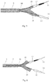
Fig. 1 is a schematic diagram of a medical device implantation apparatus of the present invention; -
Fig. 2 is an enlarged view of the distal end of the medical device implantation apparatus of the present invention; -
Fig. 3 is a cross-sectional view of an outer casing of the medical device implantation apparatus shown inFig. 1 ; -
Fig. 4 is a schematic diagram of a Y-shaped stent used in cooperation with the medical device implantation apparatus; and -
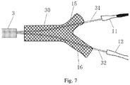
Fig. 5 to Fig. 7 are schematic diagrams showing the process of implanting a medical device by the medical device implantation apparatus. -
- 1 outer casing
- 2 inner sheath
- 3 middle sheath
- 4 outer sheath
- 5 booster sheath
- 6 handle
- 7 front handle part
- 8 rear handle part
- 9 adjusting handle
- 10 safety lock
- 11 first outer casing
- 12 second outer casing
- 13 developing part
- 14 positioning lock
- 15 first inner sheath
- 16 second inner sheath
- 21 distal end inner hole
- 22 middle section inner hole
- 23 proximal end inner hole
- 30 stent main branch
- 31, 32 stent branches
- The technical solution of the present invention is described in detail below with reference to the accompanying drawings. It should be understood that the specific embodiments described herein are only used to explain the present invention, and not to limit the present invention. The scope of the application is not limited by these embodiments, but the scope of the patent application shall prevail. In order to provide a clearer description and enable those familiar with the art to understand the application content of the present application, the various parts in the figures are not necessarily drawn according to their relative dimensions, and the ratio of certain dimensions to other relevant dimensions is highlighted and exaggerated. The details that are irrelevant or unimportant are not completely drawn in order to keep the diagram concise.
- The invention provides a medical device implantation apparatus. The medical device implantation apparatus comprises an outer sheath, a middle sheath, an inner sheath, outer casings, and a medical device, wherein the outer sheath is connected to a first portion, namely, a front handle part, of a handle and extends from a proximal end to a distal end; the middle sheath is arranged in the outer sheath, and is connected to a second portion, namely, a rear handle part, of the handle; the inner sheath is allowed to pass through the middle sheath and is connected to a third portion, namely, an adjusting handle, of the handle, and is movable relative to the outer sheath; the number of the outer casings is at least two; a distal end of the inner sheath is respectively fixedly connected to the outer casings; and the medical device is arranged around the inner sheath and partially accommodated in the outer casings. The inner sheath moves relative to the outer sheath by manipulating the third portion of the handle to release the medical device.
- According to the medical device implantation apparatus of the invention, the outer casing includes a part for fixing the inner sheath and a part for fixing the medical device. The part for fixing the inner sheath and the part for fixing the medical device can be of the same structure or different structures.
- According to the medical device implantation apparatus of the invention, the inner sheath includes a first inner sheath and a second inner sheath which are distributed side by side, and the tail end of the distal end of the inner sheath is respectively connected to the outer casings. Preferably, the inner sheath is fixed in a middle section inner hole of the outer casing; and the medical device is partially arranged between the inner sheath and the outer casings.
- According to the medical device implantation apparatus of the invention, the first inner sheath and the second inner sheath are the same in length or different in length.
- According to the medical device implantation apparatus of the invention, the inner sheath can have a cavity at the proximal end and a bifurcation structure at the distal end, and the tail end of the bifurcation structure of the inner sheath is respectively connected to the outer casings.
- According to the medical device implantation apparatus of the invention, the medical device is a stent, and the medical device can also be a medical catheter.
- According to the medical device implantation apparatus of the invention, the middle sheath is connected to the second portion of the handle through a booster sheath, and the proximal end of the middle sheath is fixedly connected to the booster sheath and then connected to the handle. The proximal end of the middle sheath can also be directly connected to the handle.
- According to the medical device implantation apparatus of the invention, the booster sheath is made of metal, including medical stainless steel.
- According to the medical device implantation apparatus of the invention, a positioning lock is arranged between the first portion of the handle and the second portion of the handle.
- According to a using method of the medical device implantation apparatus of the invention, the first portion of the handle is withdrawn towards the proximal end, and part of the medical device is released from the outer sheath, specifically, branch parts of the medical device assembled in the outer sheath are separated from the outer sheath; then the third portion of the handle is pushed towards the distal end, and the medical device is separated from the outer casings, specifically, the medical device assembled in the outer casings is separated from the outer casings; and finally, the first portion of the handle is withdrawn, the main branch of the medical device is withdrawn from the outer sheath, and the release and implantation are completed.
- As shown in
Fig. 1 to Fig. 4 , the present invention provides a medical device implantation apparatus, which includes anouter casings 1, aninner sheath 2, amiddle sheath 3, an outer sheath 4, abooster sheath 5, and a handle 6, wherein the handle 6 includes three parts, specifically the front handle part 7, the rear handle part 8, and the adjusting handle 9. - The number of the
outer casings 1 can be two or more. Theouter casings 1 comprises at least a firstouter casing 11 and a secondouter casing 12. The firstouter casing 11 and the secondouter casing 12 can be of one-stage type structures, two-stage type structures or three-stage type structures, and are used for fixing theinner sheath 2 and containing the medical device. Preferably, as shown inFig. 3 , the firstouter casing 11 and the secondouter casing 12 are of hollow three-stage structures, and each includes a distal endinner hole 21, a middle sectioninner hole 22 and a proximal endinner hole 23. Medical guide wires can extend through the distal endinner holes 21 from the proximal end to the distal end, and are used for guiding the medical device implantation apparatus to reach the desired position. Theinner sheath 2 can be fixed in the middle sectioninner holes 22. The distal endinner hole 21 and the middle sectioninner hole 22 can be designed as two parts separately or as an integral part.Compression stent branches - The
inner sheath 2 includes a firstinner sheath 15 and a secondinner sheath 16. The firstouter casing 11 and the secondouter casing 12 respectively wrap and fix the distal end of aninner sheath 2. The firstouter casing 11 and the secondouter casing 12 are located on the outer side of the distal end of theinner sheath 2. A curved angle structure with a certain arc is formed at the connection between the end surface of the distal end of theouter casing 1 and the side wall of theouter casing 1 to avoid damage to a human body lumen during use. The firstinner sheath 15 and the secondinner sheath 16 are arranged side by side, and the medical guide wires can respectively pass through the interiors of the firstinner sheath 15 and the secondinner sheath 16. The distal ends of the firstinner sheath 15 and the secondinner sheath 16 are respectively wrapped by the firstouter casing 11 and the secondouter casing 12. The proximal ends of the firstinner sheath 15 and the secondinner sheath 16 are connected to the adjusting handle 9 through the rear handle part 8. The firstinner sheath 15 and the secondinner sheath 16 are of hollow structures, and the guide wires can pass through the interiors of theinner sheath 15 and the secondinner sheath 16. In addition, theinner sheath 2 can also be designed as a distal end bifurcation structure, and portions of the distal end bifurcation structure are connected to the firstouter casing 11 and the secondouter casing 12 respectively. - The
middle sheath 3 covers at least part of theinner sheath 2. The distal end of themiddle sheath 3 is abutted against the proximal end of a stentmain branch 30 to limit the position of the stent. The proximal end of themiddle sheath 3 can be designed to be connected to the rear handle part 8, or the proximal end of themiddle sheath 3 is connected to thebooster sheath 5. Thebooster sheath 5 is of a hollow structure, and the distal end of thebooster sheath 5 is fixedly connected to the proximal end of themiddle sheath 3. Thebooster sheath 5 is made of metal, which helps to transmit force when the medical device is released. The proximal end of thebooster sheath 5 is connected to the rear handle part 8. As themiddle sheath 3 is made of polymer plastic, themiddle sheath 3 is relatively soft; and thebooster sheath 5 is made of metal, such as medical stainless steel. Therefore, themiddle sheath 3 has good flexibility and bendability when entering the human body lumen, and thebooster sheath 5 is helpful for the transmission of force during the implantation and release of the medical device. A developingpart 13 is arranged on the outer wall of the distal end of themiddle sheath 3. The developingpart 13 can be embedded on the outer wall of themiddle sheath 3 or placed on the outer surface of themiddle sheath 3 in other ways, which facilitates the positioning and release of the medical device during the operation. - The outer sheath 4 is located on the outer side of the
middle sheath 3, covers at least part of themiddle sheath 3, and is movable relative to theinner sheath 2. The proximal end of the outer sheath 4 is connected to a front handle part 7. The outer side of the outer sheath 4 can be surrounded by soft materials, so that during surgery, especially when the outer sheath turns a corner, the irritation to the human body lumen can be reduced. - The handle 6 is located at the proximal end of the medical device implantation apparatus and comprises the front handle part 7, the rear handle part 8 and the adjusting handle 9. The front handle part 7 is located at the distal end of the handle 6 and is connected to the proximal end of the outer sheath 4. The proximal end of the front handle 7 is provided with a
safety lock 10 composed of a locking screw and a locking nut. The front handle part 7 can be fixed on thebooster sheath 5 by screwing, and plays a role in positioning. The rear handle part 8 is located between the front handle part 7 and the adjusting handle 9 and is connected to the proximal end of thebooster sheath 5. The adjusting handle 9 is located at the proximal end of the medical device implantation apparatus, and is connected to the tail end of the proximal end of theinner sheath 2. A positioning lock 14 is arranged between the front handle part 7 and the rear handle part 8 and covers theboost sheath 5. - The
outer casing 1 can be used for compressing the stent. The stent can include the stentmain branch 30 and thestent branches stent branches Fig. 4 , the twostent branches inner sheath 15 and the secondinner sheath 16 are different in length, the twobranches inner sheath 15 and the secondinner sheath 16, thereby being compressed into the firstouter casing 11 and the secondouter casing 12 respectively. Thestent branches inner holes 23 of theouter casing 1. - The medical device implantation apparatus of the present invention can convey including but not limited to the self-expandable stent, and can also convey other medical devices that can be released from the implantation apparatus by withdrawing the outer sheath 4 relative to the
inner sheath 2. - As shown in
Fig. 5 to Fig. 7 , the implantation process of the medical device implantation apparatus is as follows: firstly, the distal ends of the twostent branches outer casing 1; then themain stent 30 covers theinner sheath 2, and the positioning lock 14 is locked, so that themain stent 30 is fixed on thebooster sheath 5; after the outer sheath 4 covers the stentmain branch 30 and thestent branches safety lock 10 is screwed, and the stent assembly is completed. When the positioning lock 14 is fixed, the position of the the positioning lock is close to thesafety lock 10, and can prompt the doctor that when the front handle part 7 is withdrawn to the positioning lock 14, thestent branches - When the medical device implantation apparatus is in use, firstly, the two medical guide wires pass through the
inner sheath 2 respectively, and under the guidance of the medical guide wires, the medical device implantation apparatus reaches the position of the lesion, and at the moment, thesafety lock 10 and the positioning lock 14 are both locked. Thesafety lock 10 of the medical device implantation apparatus is unscrewed, the rear handle part 8 and the adjusting handle 9 are fixed, the front handle part 7 is withdrawn, and thus, the outer sheath 4 is driven to withdraw, so that thestent branches branches safety lock 10 is screwed. Then the front handle part 7 and the rear handle part 8 are fixed, the adjusting handle 9 is pushed forward, and the adjusting handle 9 drives theinner sheath 2 to move to the distal end, thereby driving theouter casing 1 to move towards the distal end to separate the distal ends of thestent branches outer casing 1. At the moment, the bifurcation of the branch abuts against the human body lumen, thesafety lock 10 and the positioning lock 14 are unscrewed, the rear handle part 8 is fixed, and the front handle part 7 is withdrawn, so that the stentmain branch 30 is partially pushed out of the outer sheath 4, and the medical device release process is completed. - The above are only the preferred embodiments of the present invention, and do not limit the present invention in any form. Although the present invention has been disclosed in the preferred embodiments as above, the preferred embodiments are not intended to limit the present invention. Anyone skilled in the art can use the technical content disclosed above to make slight changes or decoration into equivalent embodiments with equivalent changes without departing from the scope of the technical solution of the present invention, but any content that does not depart from the technical solution of the present invention, and any simple modifications, equivalent changes and decoration made to the above embodiments according to the technology essence of the present invention still fall within the scope of the technical solution of the present invention.
Claims (10)
- A medical device implantation apparatus, comprising:an outer sheath, connected to a first portion of a handle and extending from a proximal end to a distal end;a middle sheath, the middle sheath being arranged in the outer sheath, and the middle sheath being connected to a second portion of the handle;an inner sheath, the inner sheath being allowed to pass through the middle sheath, the inner sheath being connected to a third portion of the handle, and the inner sheath being movable relative to the outer sheath;outer casings, with at least two outer casings being provided, and a distal end of the inner sheath being respectively fixedly connected to the outer casings; anda medical device, arranged around the inner sheath and partially accommodated in the outer casings, wherein the inner sheath moves relative to the outer sheath by manipulating the third portion of the handle to release the medical device.
- The medical device implantation apparatus according to claim 1, wherein the outer casing comprises a part for fixing the inner sheath and a part for fixing the medical device.
- The medical device implantation apparatus according to claim 1, wherein the inner sheath has a distal end bifurcation structure that is respectively connected to the outer casings.
- The medical device implantation apparatus according to claim 1, wherein the inner sheath comprises a first inner sheath and a second inner sheath which are distributed side by side, and the tail end of the distal end of the inner sheath is respectively connected to the outer casings.
- The medical device implantation apparatus according to claim 4, wherein the first inner sheath and the second inner sheath are the same in length or different in length.
- The medical device implantation apparatus according to claim 1, wherein the medical device is a stent.
- The medical device implantation apparatus according to claim 1, wherein the middle sheath is connected to the second portion of the handle through a booster sheath.
- The medical device implantation apparatus according to claim 7, wherein the booster sheath is made of metal.
- The medical device implantation apparatus according to claim 1, wherein a positioning lock is arranged between the first portion of the handle and the second portion of the handle.
- A method of using a medical device implantation apparatus, comprising:withdrawing a first portion of a handle towards a proximal end, and part of a medical device is released from an outer sheath;pushing a third portion of the handle towards a distal end, and the medical device is separated from outer casings; andwithdrawing the first portion of the handle finally, and the medical device is released and implanted.
Applications Claiming Priority (2)
| Application Number | Priority Date | Filing Date | Title |
|---|---|---|---|
| CN201811017972.6A CN110870813A (en) | 2018-09-03 | 2018-09-03 | Medical instrument imbedding device |
| PCT/CN2019/102165 WO2020048325A1 (en) | 2018-09-03 | 2019-08-23 | Medical instrument implantation apparatus |
Publications (2)
| Publication Number | Publication Date |
|---|---|
| EP3848007A1 true EP3848007A1 (en) | 2021-07-14 |
| EP3848007A4 EP3848007A4 (en) | 2022-06-01 |
Family
ID=69716500
Family Applications (1)
| Application Number | Title | Priority Date | Filing Date |
|---|---|---|---|
| EP19858546.5A Pending EP3848007A4 (en) | 2018-09-03 | 2019-08-23 | Medical instrument implantation apparatus |
Country Status (4)
| Country | Link |
|---|---|
| US (1) | US11969370B2 (en) |
| EP (1) | EP3848007A4 (en) |
| CN (1) | CN110870813A (en) |
| WO (1) | WO2020048325A1 (en) |
Family Cites Families (15)
| Publication number | Priority date | Publication date | Assignee | Title |
|---|---|---|---|---|
| US6514281B1 (en) * | 1998-09-04 | 2003-02-04 | Scimed Life Systems, Inc. | System for delivering bifurcation stents |
| US6398802B1 (en) * | 1999-06-21 | 2002-06-04 | Scimed Life Systems, Inc. | Low profile delivery system for stent and graft deployment |
| US20060293695A1 (en) * | 1999-07-20 | 2006-12-28 | Ricci Donald R | Bifurcated stent delivery system and method of use |
| EP2036519A1 (en) * | 2007-09-16 | 2009-03-18 | Ophir Perelson | Bifurcation stent and stent delivery assembly |
| US8292941B2 (en) * | 2009-04-23 | 2012-10-23 | Medtronic Vascular, Inc. | Delivery system for deployment of a one-piece iliac-branch device |
| US8337542B2 (en) * | 2010-07-14 | 2012-12-25 | Cook Medical Technologies Llc | Delivery system for simultaneous deployment of intraluminal device |
| CN102525698A (en) * | 2010-12-31 | 2012-07-04 | 微创医疗器械(上海)有限公司 | Interposed medical appliance delivery and release device |
| WO2012109365A1 (en) | 2011-02-08 | 2012-08-16 | Advanced Bifurcation Systems, Inc. | System and methods for treating a bifurcation with a fully crimped stent |
| US9439796B2 (en) * | 2013-03-15 | 2016-09-13 | Cook Medical Technologies Llc | Prosthesis delivery device |
| CN203677329U (en) * | 2013-10-25 | 2014-07-02 | 常州乐奥医疗科技有限公司 | Novel bracket releasing device |
| CN105943092B (en) * | 2016-04-19 | 2018-08-24 | 南京微创医学科技股份有限公司 | A kind of safe locking device |
| CN105943029B (en) * | 2016-05-04 | 2019-05-14 | 深圳诺康医疗设备股份有限公司 | ECG electrode piece, leading wire connector terminal and ECG measuring device |
| CN106420129B (en) * | 2016-11-04 | 2019-02-01 | 南京微创医学科技股份有限公司 | A kind of drug-carrying self-expansion type non-vascular orifice bracket conveying device |
| CN107374792A (en) * | 2017-07-21 | 2017-11-24 | 李麟荪 | A kind of integral type layered-scaffold implanting device |
| CN209499996U (en) * | 2018-09-03 | 2019-10-18 | 南京微创医学科技股份有限公司 | A kind of medical instrument embedded device |
-
2018
- 2018-09-03 CN CN201811017972.6A patent/CN110870813A/en active Pending
-
2019
- 2019-08-23 WO PCT/CN2019/102165 patent/WO2020048325A1/en unknown
- 2019-08-23 US US17/272,448 patent/US11969370B2/en active Active
- 2019-08-23 EP EP19858546.5A patent/EP3848007A4/en active Pending
Also Published As
| Publication number | Publication date |
|---|---|
| WO2020048325A1 (en) | 2020-03-12 |
| CN110870813A (en) | 2020-03-10 |
| US11969370B2 (en) | 2024-04-30 |
| US20210322192A1 (en) | 2021-10-21 |
| EP3848007A4 (en) | 2022-06-01 |
Similar Documents
| Publication | Publication Date | Title |
|---|---|---|
| EP2683285B1 (en) | Vacuum system and endoscopy arrangement for endoscopic vacuum therapy | |
| EP3666202A1 (en) | Systems and methods for embolic implant detachment | |
| US7717928B2 (en) | Anastomosis device configurations and methods | |
| CN102137644B (en) | Introducer for endovascular implants | |
| US4682599A (en) | Basket forceps assembly for endoscope | |
| CN110292464A (en) | Adjustable bending intervenes valve delivery system | |
| CN104042299A (en) | Occlusive device delivery system with mechanical detachment | |
| US8092468B2 (en) | Deployment handle for an implant deployment device | |
| US20090054905A1 (en) | Embolization coil delivery systems and methods | |
| US20100305594A1 (en) | Percutaneous vein harvester with shielded blade | |
| CA2254052A1 (en) | Methods and systems for deployment of a detachable balloon at a target site in vivo | |
| EP3583916A3 (en) | Apparatus for facilitating deployment of an endoluminal prosthesis | |
| US20050283193A1 (en) | Introducer guide | |
| AU2011335890B2 (en) | Device for retrieving a body from a tubular structure | |
| EP3554607B1 (en) | Medical probe | |
| JP7162727B2 (en) | Double-lumen end caps used in quarry baskets and quarry baskets | |
| CN211934231U (en) | Lead extraction device | |
| CN112656559B (en) | A pull out device for pulling out ureteral stent | |
| GB2487527A (en) | Needle and curved catheter | |
| US11969370B2 (en) | Medical device implantation apparatus | |
| CN109350324B (en) | Distal bendable stent implantation device | |
| CN109350322B (en) | Double-bracket implantation device | |
| AU2004289277A1 (en) | Endovascular guide for use with a percutaneous device for harvesting tubular body members | |
| WO2022129959A1 (en) | Catheter | |
| US20130282036A1 (en) | Wireguide set for changing access sites |
Legal Events
| Date | Code | Title | Description |
|---|---|---|---|
| STAA | Information on the status of an ep patent application or granted ep patent |
Free format text: STATUS: THE INTERNATIONAL PUBLICATION HAS BEEN MADE |
|
| PUAI | Public reference made under article 153(3) epc to a published international application that has entered the european phase |
Free format text: ORIGINAL CODE: 0009012 |
|
| STAA | Information on the status of an ep patent application or granted ep patent |
Free format text: STATUS: REQUEST FOR EXAMINATION WAS MADE |
|
| 17P | Request for examination filed |
Effective date: 20210309 |
|
| AK | Designated contracting states |
Kind code of ref document: A1 Designated state(s): AL AT BE BG CH CY CZ DE DK EE ES FI FR GB GR HR HU IE IS IT LI LT LU LV MC MK MT NL NO PL PT RO RS SE SI SK SM TR |
|
| DAV | Request for validation of the european patent (deleted) | ||
| DAX | Request for extension of the european patent (deleted) | ||
| A4 | Supplementary search report drawn up and despatched |
Effective date: 20220502 |
|
| RIC1 | Information provided on ipc code assigned before grant |
Ipc: A61F 2/95 20130101ALI20220425BHEP Ipc: A61F 2/06 20130101ALI20220425BHEP Ipc: A61F 2/954 20130101ALI20220425BHEP Ipc: A61F 2/966 20130101AFI20220425BHEP |
|
| STAA | Information on the status of an ep patent application or granted ep patent |
Free format text: STATUS: EXAMINATION IS IN PROGRESS |
|
| 17Q | First examination report despatched |
Effective date: 20230327 |
|
| GRAP | Despatch of communication of intention to grant a patent |
Free format text: ORIGINAL CODE: EPIDOSNIGR1 |
|
| STAA | Information on the status of an ep patent application or granted ep patent |
Free format text: STATUS: GRANT OF PATENT IS INTENDED |
|
| INTG | Intention to grant announced |
Effective date: 20240729 |