EP3847974B1 - Lateral access system - Google Patents
Lateral access system Download PDFInfo
- Publication number
- EP3847974B1 EP3847974B1 EP20210090.5A EP20210090A EP3847974B1 EP 3847974 B1 EP3847974 B1 EP 3847974B1 EP 20210090 A EP20210090 A EP 20210090A EP 3847974 B1 EP3847974 B1 EP 3847974B1
- Authority
- EP
- European Patent Office
- Prior art keywords
- blade
- retractor
- arm
- blade holder
- blades
- Prior art date
- Legal status (The legal status is an assumption and is not a legal conclusion. Google has not performed a legal analysis and makes no representation as to the accuracy of the status listed.)
- Active
Links
Images










Classifications
-
- A—HUMAN NECESSITIES
- A61—MEDICAL OR VETERINARY SCIENCE; HYGIENE
- A61B—DIAGNOSIS; SURGERY; IDENTIFICATION
- A61B17/00—Surgical instruments, devices or methods
- A61B17/02—Surgical instruments, devices or methods for holding wounds open, e.g. retractors; Tractors
- A61B17/0206—Surgical instruments, devices or methods for holding wounds open, e.g. retractors; Tractors with antagonistic arms as supports for retractor elements
-
- A—HUMAN NECESSITIES
- A61—MEDICAL OR VETERINARY SCIENCE; HYGIENE
- A61B—DIAGNOSIS; SURGERY; IDENTIFICATION
- A61B17/00—Surgical instruments, devices or methods
- A61B17/02—Surgical instruments, devices or methods for holding wounds open, e.g. retractors; Tractors
- A61B17/025—Joint distractors
-
- A—HUMAN NECESSITIES
- A61—MEDICAL OR VETERINARY SCIENCE; HYGIENE
- A61B—DIAGNOSIS; SURGERY; IDENTIFICATION
- A61B17/00—Surgical instruments, devices or methods
- A61B2017/00367—Details of actuation of instruments, e.g. relations between pushing buttons, or the like, and activation of the tool, working tip, or the like
-
- A—HUMAN NECESSITIES
- A61—MEDICAL OR VETERINARY SCIENCE; HYGIENE
- A61B—DIAGNOSIS; SURGERY; IDENTIFICATION
- A61B17/00—Surgical instruments, devices or methods
- A61B2017/00367—Details of actuation of instruments, e.g. relations between pushing buttons, or the like, and activation of the tool, working tip, or the like
- A61B2017/00407—Ratchet means
-
- A—HUMAN NECESSITIES
- A61—MEDICAL OR VETERINARY SCIENCE; HYGIENE
- A61B—DIAGNOSIS; SURGERY; IDENTIFICATION
- A61B17/00—Surgical instruments, devices or methods
- A61B2017/00831—Material properties
- A61B2017/00902—Material properties transparent or translucent
- A61B2017/00915—Material properties transparent or translucent for radioactive radiation
- A61B2017/0092—Material properties transparent or translucent for radioactive radiation for X-rays
-
- A—HUMAN NECESSITIES
- A61—MEDICAL OR VETERINARY SCIENCE; HYGIENE
- A61B—DIAGNOSIS; SURGERY; IDENTIFICATION
- A61B17/00—Surgical instruments, devices or methods
- A61B17/02—Surgical instruments, devices or methods for holding wounds open, e.g. retractors; Tractors
- A61B17/025—Joint distractors
- A61B2017/0256—Joint distractors for the spine
Definitions
- the present disclosure relates to devices used in accessing a spinal work location. More particularly, the present disclosure relates to devices and methods for laterally accessing a spinal work location.
- the physician may insert one or more prosthetic spacers between the affected vertebrae to maintain normal disc spacing and/or the normal amount of lordosis in the affected region.
- a prosthetic implant is inserted between the adjacent vertebrae and may include pathways that permit bone growth between the adjacent vertebrae until they are fused together.
- US2019/216570A1 , US2016/317137A1 and US9622732B2 disclose devices and methods for inserting spinal fixations fixation or stabilization of an affected vertebra. As is typical, the intervertebral spaces are accessed either anteriorly or posteriorly. It would be desirable to access the intervertebral spaces via a lateral approach.
- a surgical retractor comprises a body portion including a first blade holder and a first blade detachably secured to the first blade holder and first and second retractor arms operatively coupled to the body portion.
- the body portion comprises a tube assembly comprising a rotatable knob.
- the first blade holder is operatively coupled with the rotatable knob such that rotation of the rotatable knob causes axial displacement of the first blade holder.
- the first blade is configured for axial displacement with the first blade holder and angulation relative to the first blade holder about a first toeing axis.
- the first and second mounting wings extend from opposing sides of the tube assembly.
- a first drive pin secures the first retractor arm to the first mounting wing and defines a first pivot axis about which the first drive pin rotates to pivot the first retractor arm relative to the tube assembly and the second retractor arm.
- a second drive pin secures the second retractor arm to the second mounting wing and defines a second pivot axis about which the second drive pin rotates to pivot the second retractor arm relative to the tube assembly and the first retractor arm.
- the first and second retractor arms include respective second and third blades detachably secured thereto.
- the first and second retractor arms are transitionable between an approximated configuration in which the second and third blades are proximate each other, and a spaced apart configuration in which the second and third blades are spaced apart from each other.
- the second and third blades are further configured to angulate about respective second and third toeing axes that are defined by the respective first and second retractor arms.
- At least a portion of the first or second retractor arms may be made of a carbon fiber material.
- At least a portion of the first blade, second blade or third blade may be made of a carbon fiber material.
- At least a portion of the first blade, second blade or third blade may be made of metal.
- first and second retractor arms are pivotably coupled to respective opposing sides of the body portion.
- the first blade holder may be configured to secure the first blade thereto by a locking screw.
- the first blade may be configured for axial displacement independent of the angulation thereof.
- the first blade may be configured to angulate about the first axis orthogonal to a longitudinal axis defined by the body portion.
- first and second retractor arms may include a ratchet mechanism to maintain respective relative positions of the first and second retractor arms with respect to the body portion.
- the first or second retractor arm may include a handle portion, an arm toeing base, and a blade holder configured to secure the corresponding second or third blade thereto.
- the blade holder may be coupled to the arm toeing base by a toeing screw that is rotatable to enable the blade holder to rotate relative to the arm toeing base.
- first, second, and third blades may be configured to define a cavity when proximate each other.
- At least a portion of the arm toeing base may be made of a carbon fiber material.
- At least a portion of the blade holder is made of a carbon fiber material.
- first, second and third blades may be configured to define a cavity when proximate each other.
- the cavity may have a triangular shape.
- the first blade is configured to support an intradiscal shim.
- the first blade may be configured to lock a relative position of the intradiscal shim thereto.
- the second and third blades when the first and second retractor arms are in the approximated configuration, may define a gap of about 1 mm.
- a method of surgery includes inserting an inner cylindrical dilator through psoas muscle; positioning the inner cylindrical dilator onto a disc; advancing an intradiscal guidewire into the disc through the inner cylindrical dilator; placing an outer triangular dilator over the intradiscal guidewire and the inner cylindrical dilator; transitioning first and second retractor arms of a surgical retractor to an approximated position to place first and second blades coupled to the respective first and second retractor arms proximate each other; placing the first and second blades adjacent the outer triangular dilator; rotating a rotatable knob of the surgical retractor to cause axial displacement of a posterior blade of the surgical retractor towards the first and second blades such that the first and second blades and the posterior blade define a triangular opening around the outer triangular dilator; advancing the first and second blades and the posterior blade along the outer triangular dilator into tissue to engage a
- manipulating the first blade, the second blade, or the posterior blade may include angulating the first blade, the second blade, or the posterior blade.
- transitioning the first and second retractor arms may include pivoting the first and second retractor arms about respective pivots.
- the method may further include determining a blade length of the first and second blades by reading markings on the outer triangular dilator in relation to a skin level.
- the method may further include mounting the first, second, and posterior blades to the surgical retractor.
- the method may further include securing the surgical retractor to an operating table via table mounts.
- the method may further include attaching an intradiscal shim to the posterior blade.
- a surgical retractor in accordance with another embodiment of the disclosure, includes a body portion and first and second retractor arms operatively coupled to the body portion.
- the body portion includes a rotatable knob, a first blade holder and a first blade.
- the first blade holder is operatively coupled with the rotatable knob such that rotation of the rotatable knob causes axial displacement of the first blade holder.
- the first blade is detachably secured with the first blade holder and is configured for axial displacement with the first blade holder and angulation relative to at least part of the body portion about a first axis.
- the first and second retractor arms include respective second and third blades detachably secured thereto, the first and second retractor arms transitionable between an approximated configuration in which the second and third blades are proximate each other, and a spaced apart configuration in which the second and third blades are spaced apart from each other.
- the second and third blades are configured to angulate about respective second and third axes that are defined by the respective first and second retractor arms.
- At least a portion of the first retractor arm, the second retractor arm, the first blade, the second blade or the third blade may be made of a carbon fiber material.
- the first and second retractor arms may be pivotably coupled to respective opposing sides of the body portion.
- the first blade may be configured for axial displacement independent of the angulation thereof.
- the first blade may be configured to angulate about the first axis orthogonal to a longitudinal axis defined by the body portion.
- the first and second retractor arms may include a ratchet mechanism to adjust and maintain respective relative positions of the first and second retractor arms with respect to the body portion.
- the first or second retractor arm may include a handle portion, an arm toeing base, and a blade holder configured to secure the corresponding second or third blade thereto, the blade holder being coupled to the arm toeing base by a toeing screw that is rotatable to enable the blade holder to rotate relative to the arm toeing base.
- the first, second, and third blades may be configured to define a triangular shaped cavity when proximate each other.
- the first blade may have a first inner surface and the second and third blades may have a second inner surface different from the first inner surface.
- the first blade may include a first rail, a second rail and a longitudinal receiving trough in between the first and second rails, the first blade being configured to support an intradiscal shim.
- the first rail may include a first cutout and the second rail may include a second cutout, the first and second cutouts being configured to lock the intradiscal shim relative to the first blade.
- the first rail may include a third cutout and the second rail may include a fourth cutout, the third cutout being different in shape from the first cutout.
- the second and third blades when the first and second retractor arms are in the approximated configuration, may define a gap of about 1 mm.
- the body portion may further include a tube assembly and a shaft arm assembly extending from the tube assembly, the first blade holder being attached to an end of the shaft arm assembly opposite the tube assembly, and the shaft arm assembly being translatable in predetermined increments relative to the tube assembly to cause axial displacement of the first blade holder.
- the body portion may include a toeing screw adjacent to the first blade holder such that rotation of the toeing screw causes the first blade holder to rotate relative to the shaft arm assembly.
- distal refers to that portion of the instrument, or component thereof which is farther from the user while the term “proximal” refers to that portion of the instrument or component thereof which is closer to the user.
- proximal refers to that portion of the instrument or component thereof which is closer to the user.
- the term “about” means that the numerical value is approximate and small variations would not significantly affect the practice of the disclosed embodiments.
- a surgical retractor in accordance with an embodiment of the present disclosure is generally shown as a surgical retractor 100.
- the surgical retractor 100 may be utilized in accessing, e.g., lumbar vertebrae, using a trans-psoas approach. It is contemplated that the surgical retractor 100 may be utilized in, e.g., discectomy, laminectomy, transforaminal or posterior lumbar interbody fusion (TLIF/PLIF), or posterior fixation (e.g., pedicle screw system).
- the surgical retractor 100 enables the surgeon to perform, e.g., an open procedure, in minimal space with reduced tissue damage.
- the surgical retractor 100 used in such procedures may reduce blood loss, improve recovery time, and/or reduce scarring.
- the surgical retractor 100 may be used as part of a lateral access surgical system including a dilator assembly 301 ( FIG. 11 ) including an inner cylindrical dilator 200 ( FIG. 12 ) and an outer triangular dilator 300 ( FIG. 13 ), an intradiscal shim 600 ( FIG. 14a ), a widening shim 700 ( FIG. 16a ), a lengthening shim 800 ( FIG. 18 ), an intradiscal guidewire 900 ( FIG. 11a ), and a stimulation probe 1000 ( FIG. 19 ), as will be described below.
- the surgical retractor 100 includes a tube assembly 110 and first and second retractor arms 120, 130 operatively coupled to respective opposing sides of the tube assembly 110.
- the first and second retractor arms 120, 130 are pivotably coupled to the tube assembly 110 about respective pivots "P1", "P2" such that distal ends of the respective first and second retractor arms 120, 130 are transitionable between an approximated position ( FIG. 1 ) and a spaced part position ( FIG. 2 ).
- the tube assembly 110 includes a tube body 112 supporting a rotatable knob 114 on a proximal end 112a thereof and a posterior blade holder assembly 116 supported on distal end 112b thereof.
- the posterior blade holder assembly 116 includes a shaft arm assembly 116a, a posterior blade holder 116b supported on a distal end of the shaft arm assembly 116a, and a posterior blade 500 mounted on the posterior blade holder 116b.
- the shaft arm assembly 116a is operatively coupled to the rotatable knob 114 such that rotation of the rotatable knob 114 in the direction of arrows "B" (about an axis "R1") causes axial displacement of the posterior blade holder 116b, and thus, the posterior blade 500 in the direction of arrows "A".
- the shaft arm assembly 116a may include threads 117 that threadably engage the tube body 112.
- the threads 117 are disposed on lateral sides of the shaft arm assembly 116a to optimize load distribution.
- the threads 117 may be disposed on top and bottom surfaces of the shaft arm assembly 116a. Under such a configuration, the clinician may position the posterior blade 500 at a desired position, e.g., away from the tube body 112.
- the posterior blade holder 116b includes a posterior blade seat 116c configured to, e.g., detachably, secure the posterior blade 500 thereto.
- the posterior blade 500 may be detachably secured to the posterior blade seat 116c by a locking screw 116d.
- the posterior blade 500 may be detachably secured to the posterior blade holder 116b by, e.g., snap fit or friction fit.
- the posterior blade 500 may be integrally formed with the posterior blade holder 116b as a single construct. Under such a configuration, the posterior blade holder assembly 116 may be detachable from the tube body 112 or the shaft arm assembly 116a.
- the posterior blade holder 116b further includes a posterior toeing screw 116e.
- the posterior toeing screw 116e is rotatable to enable the posterior blade 500 to toe (i.e., angulate) relative to the shaft arm assembly 116a.
- the posterior blade 500 may be rotated about an axis orthogonal to the length of the posterior blade 500 to angulate opposing ends of the posterior blade 500 in opposite directions in a range from about 0 degrees to about 30 degrees.
- the posterior toeing screw 116e defines a cavity 119 having, e.g., a hex key feature, for non-slip engagement with a driving instrument to drive the posterior toeing screw 116e to cause toeing of the posterior blade 500.
- the cavity 119 may have any suitable configuration (e.g., slotted, hexagonal, square, etc.) for engagement with a complementary driving instrument.
- the posterior blade 500 is configured for selective axial displacement (towards and away from the tube body 112) and toeing (rotation about an axis orthogonal to the length of the posterior blade 500) by the clinician.
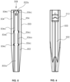
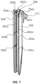
- the posterior blade 500 has a blade body 502 including first and second rails 504, 506 that project from a planar inner surface 502a of the blade body 502 to engagement surfaces 504a, 506a of the respective first and second rails 504, 506.
- the first and second rails 504, 506 taper inwardly toward one another and define cutouts 504b, 506b so that the first and second rails 504, 506 overhang a planar inner surface 502a to define an open longitudinal receiving trough 508 that is c-shaped for retaining an intradiscal shim 600 ( FIGS. 14a and 14b ).
- the engagement surfaces 504a, 506a are configured to complement an outer surface 303 of an outer triangular dilator 300 ( FIGS. 11 and 13 ).
- the planar inner surface 502a defines a recess 502b in a proximal end portion thereof.
- the first and second rails 504, 506 further include cutouts 504c, 506c, respectively, that extend into open longitudinal receiving trough 508 for limiting insertion depth or retraction of the intradiscal shim 600 relative to the posterior blade 500.
- the cutouts 504c, 506c are also configured to lock the intradiscal shim 600 at a fixed depth.
- the blade body 502 also includes a mounting hook 512 supported on a proximal end thereof for securing the blade body 502 to the posterior blade seat 116c ( FIG. 2 ) of the posterior blade holder 116b of retractor 100.
- the tube assembly 110 further includes mounting wings 118a, 118b that extend from opposing sides of the tube assembly 110.
- the first and second retractor arms 120, 130 are pivotably coupled to the tube assembly 110 about the first and second pivots "P1" and "P2.”
- the first retractor arm 120 includes a first handle portion 122, a first blade holder 124, and a first arm toeing base 123 configured to support the first blade holder 124 on the first retractor arm 120.
- the first blade holder 124 is coupled to the first retractor arm 120 by a first toeing screw 126 that is rotatable to enable first blade holder 124 to toe relative to first arm toeing base 123 about toeing axis "T1" defined through the first retractor arm 120.
- the first retractor arm 120 further supports a first locking pawl 122a defining a ratchet mechanism with the mounting wing 118a, and the first drive pin 122b that secures the first retractor arm 120 to the mounting wing 118a of the tube assembly 110.
- the first drive pin 122b defines a first pivot "P1" about which the first drive pin 122b rotates to pivot the first retractor arm 120 relative to the tube assembly 110 and the second retractor arm 130.
- the first blade holder 124 further includes a first blade seat 124a that supports a first retractor blade 400a and a first locking screw 124b to secure the first retractor blade 400a thereto such that the first retractor blade 400a may angulate with respect to the first arm toeing base 123 when the first toeing screw 126 is rotated.
- the second retractor arm 130 which mirrors first retractor arm 120, includes a second handle portion 132, a second blade holder 134, and a second arm toeing base 133 configured to support the second blade holder 134 on the second retractor arm 130.
- the second retractor arm 130 supports a second locking pawl 132a defining a ratchet mechanism with the mounting wing 118b, and a second drive pin 132b that secures the second retractor arm 132 to the mounting wing 118b of tube assembly 110.
- the second drive pin 132b defines a second pivot "P2" about which the second drive pin 132b rotates to pivot the second retractor arm 130 relative to the tube assembly 110 and the first retractor arm 120.
- the second blade holder 134 further includes a second blade seat 134a that supports a second retractor blade 400b and a second locking screw 134b to secure the second retractor blade 400b thereto so that the second retractor blade 400b can angulate with respect to the second arm toeing base 133 when the second toeing screw 136 is rotated.
- the tube assembly 110 may further include a first table mount 119a coupled to tube body 112 and a second table mount 119b coupled to posterior blade holder 116b to mount the surgical retractor 100 to a table.
- first and second arm toeing bases 123, 133 may be formed of a carbon fiber material, such as carbon fiber reinforced or filled polyetheretherketone (PEEK), to enhance structural integrity, reduce weight and improve visualization under imaging.
- PEEK polyetheretherketone
- FIGS. 4A-4D only the first arm toeing base 123 is illustrated in FIGS. 4A-4D , however, the first and second arm toeing bases 123, 133 are mirror images of each other, and thus, the features described herein with respect to the first arm toeing base 123 may be applied to the second arm toeing base 133.
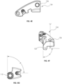
- the direction of layers of fiber incorporated into the base may define an angle ⁇ in the range of about 40 degrees and about 60 degrees, and preferably about 50 degrees, with respect to a leading edge 123 of the first arm toeing base 123 in order to optimize the strength of the part relative to the directional forces experienced during use.
- the direction of layers of fiber may define the angle ⁇ with respect to an axis extending across the bore 127 configured to receive a screw 129 ( FIG. 4 ) to secure the first arm toeing base 123 and/or the first blade holder 124 to the first retractor arm 120.
- the use of the screw 129 facilitates interchangeability of the first arm toeing base 123 and the first blade holder 124 with the manual blade assembly 2000 ( FIGS.
- the manual blade assembly may include rod-style arms attachable to and extending from the handle assembly. Blade assemblies may be attached to the rod-style arms at various locations, such as by a herth-style clamp.
- first and second blade holders 124, 134 also may be formed of a carbon fiber material to enhance structural integrity, reduce weight and improve visualization under imaging.
- first blade holder 124 is shown, however, the first and second blade holders 124, 134 are mirror images of each other, and thus, the features described herein with respect to the first blade holder 124 may be applied to the second blade holder 134.
- the direction of layers of fiber may define an angle ⁇ in the range of about 80 degrees and about 100 degrees, and preferably about 70 degrees, with respect to a trailing edge 125 of the first blade holder 124 in order to optimize the strength of the part relative to the directional forces experienced during use.
- the trailing edge 125 may be substantially parallel to an axis "P-P" defined by the bore 126 such that the direction of layers of fiber may define the angle ⁇ with respect to axis "P-P".
- the first retractor arm 120 may be partially formed of a carbon fiber material.
- first blade holder 124 and the first toeing base 123 may be formed of a carbon fiber material and the rest of the first retractor arm 120 may be formed of stainless steel or aluminum or any other biocompatible material.
- the use of carbon fiber material for all or part of the toeing bases 123, 133 and/or blade holders 124, 134 enhances visualization of the operative site, including the location and orientation of the retractor relative to the anatomy such as the vertebral bodies and end plates under x-ray or fluoroscopic imaging. This is particularly helpful during placement of the retractor.
- the posterior blade holder assembly 116 may be formed of a carbon fiber material to enhance structural integrity, reduce weight and improve visualization under imaging.
- the direction of layers of fiber may define an angle ⁇ in the range of about 80 degrees and about 100 degrees with respect to a trailing edge 115 of the posterior blade holder assembly 116.
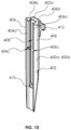
- the first and second retractor blades 400a, 400b are identical and each includes a retractor blade body 402 having first and second rails 404, 406 that project from a planar inner surface 402a of retractor blade body 402 to engagement surfaces 404a, 406a of respective first and second rails 404, 406.
- the first and second rails 404, 406 taper inwardly toward one another and define cutouts 404b, 406b so that the first and second rails 404, 406 overhang a planar inner surface 402a to define an open longitudinal receiving trough 408 that is, e.g., c-shaped, for retaining a widening shim 700 ( FIG.
- the retractor blade body 402 further includes a stop 410 disposed in the open longitudinal receiving trough 408 adjacent a distal end portion of the retractor blade body 402 to limit distal movement of the widening shim 700 or the lengthening shim 800 relative to the retractor blade body 402.
- the first and second rails 404, 406 define notches 404c, 406c therein, respectively, which are disposed in registration with the open longitudinal receiving trough 408 proximal to the stop 410 for locking the widening or lengthening shims 700, 800 at a fixed depth relative to retractor blade body 402.
- the retractor blade body 402 also includes a mounting hook 412 supported on a proximal end thereof for securing the retractor blade body 402 to the first or second blade seats 124a, 134a ( FIG. 2 ) of the respective first and second retractor arms 120, 130.
- the posterior blade 500 and the first and second retractor blades 400a, 400b may be formed of, e.g., aluminum or a carbon fiber material.
- the direction of layers of carbon fiber may be selected with respect to a particular structural component of the posterior blade 500, the first retractor blade 400a, or the second retractor blade 400b, in order to enhance structural integrity of the component and visualization of the orientation and position of the retractor relative to the patient when viewed under imaging such as fluoroscopy.
- the direction of layers of carbon fiber may define an angle ⁇ in the range of about 80 degrees and about 100 degrees, and preferably about 70 degrees, with respect to a trailing edge 401 of the first or second retractor blades 400a, 400b.
- the posterior blade 500 and the first and second retractor blades 400a, 400b may be configured for interchangeable use.
- any of the blades may be attached interchangeably with any of the blade holders 124, 134, or the posterior blade holder assembly 116.
- the surgeon advantageously may orient the retractor blades in the posterior, position relative to the operative site and patient anatomy, thereby providing maximum flexibility of use of the retractor and directions of motion of the blades during adjustment.
- the various shims disclosed herein may be formed of titanium.
- a dilator assembly 301 including an inner cylindrical dilator 200 and an outer triangular dilator 300 may be used in conjunction with the surgical retractor 100 during a surgical procedure.
- the inner cylindrical dilator 200 may include a cylindrical body 202 formed of a suitable biocompatible material such as, e.g., aluminum, that defines a circular cross-sectional outer profile.
- the inner cylindrical dilator 200 also defines a guidewire passage 202a that extends through a length of the cylindrical body 202 for receiving an intradiscal guidewire 900 therein.
- the cylindrical body 202 defines an insert window 202b through a sidewall 202c of cylindrical body 202 at a distal end portion of cylindrical body 202.
- the insert window 202b is positioned to receive an insert 206 of the inner cylindrical dilator 200 therethrough such that the cylindrical body 202 of inner cylindrical dilator 200 may support the insert 206 therein.
- the cylindrical body 202 further defines a pin hole 202d transverse to the insert window 202b for receiving a pin 208 of the inner cylindrical dilator 200 therein to pin the insert 206 to the cylindrical body 202.
- the cylindrical body 202 further includes an open side channel 202e that extends along a length of an outer surface of cylindrical body 202 into the insert window 202b.
- the insert 206 also includes an open side channel 206a that extends along an outer surface of the insert 206 and is disposed in registration with open side channel 202e of cylindrical body 202 while the insert 206 is pinned to cylindrical body 202.
- the open side channel 206a of the insert 206 extends to a distal abutment 206b that inhibits a stimulation probe 1000 ( FIG. 20 ) from advancing distally beyond the distal abutment 206b (i.e., a depth or limit stop) when stimulation probe 1000 is selectively advanced along the open side channel 206a of the insert 206.
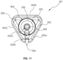
- an outer triangular dilator 300 for use with the surgical retractor 100 has a triangular body 302 with an outer surface 303 having three planar outer sides 303a, 303b, 303c.
- each planar side 303a, 303b, 303c of the triangular dilator 300 may be about 10 mm.
- the triangular body 302 defines an inner dilator passage 304 longitudinally therethrough.
- the triangular body 302 further defines an open side channel 306 along the outer surface 303 of the triangular body 302 that extends to a distal abutment 306a ( FIG. 22 ) that inhibits the stimulation probe 1000 ( FIG. 22 ) from advancing distally beyond distal abutment 306a (i.e., a depth or limit stop) when stimulation probe 1000 is selectively advanced along open side channel 306.
- the triangular cross-sectional shape of the outer dilator advantageously requires a reduced cross-sectional area relative to a corresponding circular cross-section, thereby potentially reducing trauma to tissue and decreasing insertion force during insertion.
- the triangular shape also provides positive orientation of the retractor and the outer dilator during insertion.
- the intradiscal shim 600 includes a shim body 602 that extends distally to a pointed tip 604 and includes a pair of flexible arms 606 that extend proximally from the shim body 602 and include nubs 606a that extend laterally therefrom for engaging the cutouts 504c, 506c of the posterior blade 500 to fix a position of the intradiscal shim 600 relative to posterior blade 500.
- the shim body 602 has planar front and rear surfaces and further includes a flexible finger 608 having an engagement tooth 608a projecting rearwardly therefrom. It is contemplated that the shim body 602 may define an opening 607 ( FIGS. 13a and 13b ) that may be used during an imaging process to indicate relative position of the shim body 602 with respect to the posterior blade 500. Thus, when the shim is fully deployed opening 607 will appear below the bottom edge of the blade when viewed under imaging.
- widening shims 700a, 700b include widening bodies 702a, 702b with curvilinear profiles that mirror one another.
- the widening body 702a has a lip 703a on a left side thereof and the widening body 702b has a lip 703b on a right side thereof.
- Each of the widening shims 700a, 700b further includes a pair of flexible arms 704 that extend proximally from a projection 706 that extends rearwardly from the respective widening bodies 702a, 702b.
- the projection 706 includes a nose 706a positioned to engage the stop 410 of the retractor blade body 402 of one of the first and second retractor blades 400a, 400b to limit distal movement of the respective widening shim 700a, 700b relative to retractor blade body 402 of one of the first and second retractor blades 400a, 400b.
- the flexible arms 704 include nubs 704a that are configured to secure the respective widening shims 700a, 700b to the notches 404c, 406c of the retractor blade body 402 for limiting insertion depth of the respective widening shims 700a, 700b relative to the retractor blade body 402.
- the widening shims 700a, 700b are usable with the first and second retractor blades 400a, 400b, but when supported by the first or second retractor blades 400a, 400b, the widening shims 700a, 700b do not extend past the distal ends of the respective first or second retractor blades 400a, 400b.
- a lengthening shim 800 may be used with the first and second retractor blades 400a, 400b.
- the lengthening shim 800 includes a lengthening body 802 with, e.g., a curvilinear profile, and an upper portion 802a and a lower portion 802b that are selectively movable relative to one another (in the direction of arrows "Z") in response to rotation of a lengthening screw 803 (in the direction of arrows "Y”) threadably coupled to the upper and lower portions 802a, 802b.
- the upper portion 802a includes distally-extending legs 805 that are slidably received within leg lumens 807 defined in the lower portion 802b.
- the lengthening shim 800 further includes a pair of flexible arms 806 that extend proximally from a projection 808 that extends rearwardly from the lengthening body 802.
- the projection 808 includes a nose 808a that is positioned to engage the stop 410 of the retractor blade body 402 of one of the first and second retractor blades 400a, 400b to limit distal movement of the lengthening shim 800 relative to the retractor blade body 402 of one of the first and second retractor blades 400a, 400b.
- the flexible arms 806 are configured to secure the lengthening shim 800 to the notches 404c, 406c of retractor blade body 402 for limiting insertion depth of lengthening shim 800 relative to retractor blade body 402.
- a patient may be placed in a lateral decubitus position on a patient table.
- one or more skin incisions are made at the appropriate operative level so that subcutaneous tissue layers are taken down to expose the oblique fascia.
- the muscle fibers are separated as a finger is advanced into the retroperitoneal space.
- the peritoneum is safely released anteriorly as the retroperitoneal space is further developed.
- Finger palpation of the psoas muscle or the anterior tip of the transverse process is used to confirm proper location.
- the inner cylindrical dilator 200 is introduced into the prepared path and advanced through the psoas muscle. Staying anterior to the lumbar plexus, the inner cylindrical dilator 200 is docked directly onto the disc.
- the intradiscal guidewire 900 is placed through the inner cylindrical dilator 200 and advanced into the disc, approximately halfway across the disc space as indicated through anteroposterior fluoroscopy. Additional soft tissue dilation is then performed with the outer triangular dilator 300 being advanced over the guidewire 900 and the inner cylindrical dilator 200 so that intradiscal guidewire 900 and the inner cylindrical dilator 200 are received through the inner dilator passage 304 of the outer triangular dilator 300 ( FIG. 5 ).
- blade length of the first and second retractor blades 400a, 400b, and the posterior blade 500 may be determined by markings located on the outer triangular dilator 300 in relation to the skin level.
- the first and second retractor blades 400a, 400b, and the posterior blade 500 are available from about 80 to about 180 mm in, e.g., 10 mm, increments.
- open side channels 202e, 206a along the outer surfaces of the inner cylindrical dilator 200 and the insert 206 or open side channel 306 along the outer surface of triangular body 302 can be utilized to receive a stimulation probe 1000 for advancing stimulation probe 1000 relative to the inner cylindrical dilator 200 and the outer triangular dilator 300.
- a distal tip 1002 of stimulation probe 1000 engages the distal abutment 206b.
- the distal tip 102 of the stimulation probe 1000 engages the distal abutment 306a.
- the first and second retractor blades 400a, 400b, and the posterior blade 500 are mounted to the surgical retractor 100 and locked thereto via locking screws 116d, 124b, 134b of the surgical retractor 100.
- the surgeon may elect to use blades made of metal (e.g., aluminum) or a carbon fiber material and have such blades attached to the retractor blade holders.
- the first and second retractor blades 400a, 400b are mounted to the respective first and second retractor arms 120, 130.
- the posterior blade 500 is mounted to the posterior blade holder assembly 116. As pointed out above, however, different blade mounting orientations are permitted, if desired.
- the intradiscal shim 600 is positioned within the open longitudinal receiving trough 508 of posterior blade 500 without being deployed past a distal end of posterior blade 500 prior to blade insertion into tissue ( FIG. 15 ).
- proximal movement of the intradiscal shim 600 causes the engagement tooth 608a to engage the recess 502b of the posterior blade 500 so that the intradiscal shim 600 cannot be removed from posterior blade 500 while the posterior blade 500 is secured to the retractor 100 as access to the recess 502b is only possible when the posterior blade 500 is removed from the retractor 100.
- the first and second retractor arms 120, 130 are pivoted about respective pivots "P1", “P2” to move the first and second retractor arms 120, 130 to be approximated about the outer surface 303 of the outer triangular dilator 300 so that first retractor blade 400a is spaced from second retractor blade 400b by, e.g., about 1 mm ( FIG. 28 ).
- the first and second retractor arms 120, 130 may also be pivoted about respective pivots "P1", “P2” to move the first and second retractor arms 120, 130 from the approximated position to an open position as desired.
- the rotatable knob 114 is also rotated in a first direction to translate the posterior blade holder assembly 116 distally away from the tube assembly 110 of the surgical retractor 100 until the posterior blade 500 engages the outer triangular dilator 300 and is disposed in close approximation with the first and second retractor blades 400a, 400b so that the first and second retractor blades 400a, 400b, and the posterior blade 500 define a triangular opening around the outer triangular dilator 300.
- the triangular opening provides a reduced surface area compared to, e.g., a circular opening, which may reduce tissue trauma, as well as resistance to dilation during advancement.
- the rotatable knob 114 can also be rotated in a second direction to translate the posterior blade holder assembly 116 proximally toward the tube assembly 110 as desired.
- first and second retractor blades 400a, 400b, and the posterior blade 500 can then be advanced down the outer triangular dilator 300 into the tissue to engage the spine "S" with the first and second handle portions 122, 132 of the first and second retractor arms 120, 130 oriented toward the posterior aspect of the patient. Then, under fluoroscopy, the positioning of the first and retractor blades 400a, 400b, and the posterior blade 500 seated onto the disc space and properly aligned in lateral and anteroposterior views is verified. Use of carbon fiber materials may improve visualization of the orientation and position of the retractor relative to the patient when viewed under imaging such as fluoroscopy.
- the surgical retractor 100 can then be secured via first and/or second table mounts 119a, 119b using a table mount attachment (not shown).
- the intradiscal shim 600 can be deployed relative to the posterior blade 500 into the disc space to a desired depth and secured to the posterior blade 500 via flexible arms 606 ( FIG. 13b ). Under imaging such as fluoroscopic imaging hole 607 will be visible beyond the tip of the blade when the shim is fully deployed.
- Each of the first and second retractor blades 400a, 400b, and posterior blade 500 can be independently manipulated to expand the operative corridor ( FIG. 4 ).
- the first and second retractor arms 120, 130 can be pivoted about respective pivots "P1", "P2" by squeezing the first and second handle portions 122, 132 together or turning the first and/or second drive pins 122b, 132b of the respective first and second retractor arms 120, 130.
- the first and second retractor blades 400a, 400b can also be toed as desired via turning of first and/or second toeing screws 126, 136 of respective first and second retractor arms 120, 130 ( FIG.
- an anterior arm 1100 advantageously is designed and constructed to allow sliding movement of one end 1100a of the anterior arm 1100 relative to a cross-connecting arm portion 1100b. In this manner, the anterior arm 1100, with or without blade 1200 ( FIG. 24 ) attached to the anterior arm 1100, may be permitted to lengthen or shorten during adjustment of the first and second retractor arms 120, 130.
- retractor arms 120, 130 may be adjusted relative to the spacing of the tips of the first and second retractor arms 120, 130 without having to remove the cross-connecting anterior arm 1100 or the anterior blade 1200. It is also contemplated that a locking mechanism may be provided to lock the anterior arm 1100 in position and prevent sliding adjustment of the arm when the locking mechanism is engaged.
- the inner cylindrical dilator 200 and the outer triangular dilator 300 can be removed from the assembly to expose the operative site.
- a bifurcated reusable light source (not shown) can be utilized for lighting the operative corridor.
- an anterior arm 1100 and blade 1200 can be mounted to the retractor 100 as shown in FIG. 24 .
Landscapes
- Health & Medical Sciences (AREA)
- Life Sciences & Earth Sciences (AREA)
- Surgery (AREA)
- Heart & Thoracic Surgery (AREA)
- Engineering & Computer Science (AREA)
- Biomedical Technology (AREA)
- Nuclear Medicine, Radiotherapy & Molecular Imaging (AREA)
- Medical Informatics (AREA)
- Molecular Biology (AREA)
- Animal Behavior & Ethology (AREA)
- General Health & Medical Sciences (AREA)
- Public Health (AREA)
- Veterinary Medicine (AREA)
- Surgical Instruments (AREA)
Description
- This application claims the benefit of and priority to
U.S. Provisional Patent Application No. 62/941,096, filed November 27, 2019 U.S. Patent Application No. 16/832,599, filed March 27, 2020 - The present disclosure relates to devices used in accessing a spinal work location. More particularly, the present disclosure relates to devices and methods for laterally accessing a spinal work location.
- Disease, the effects of aging, or physical trauma resulting in damage to the spine has been treated in many instances by fixation or stabilization of the affected vertebra. A wide variety of spinal fixation devices have been employed in surgical procedures for correcting spinal injuries and the effects of spinal diseases.
- After a partial or complete discectomy, the normally occupied space between adjacent vertebral bodies is subject to collapse and/or misalignment due to the absence of all or a part of the intervertebral disc. In such situations, the physician may insert one or more prosthetic spacers between the affected vertebrae to maintain normal disc spacing and/or the normal amount of lordosis in the affected region.
- Typically, a prosthetic implant is inserted between the adjacent vertebrae and may include pathways that permit bone growth between the adjacent vertebrae until they are fused together.
US2019/216570A1 ,US2016/317137A1 andUS9622732B2 - One or more of the above objects is achieved with a surgical retractor in accordance with claim 1. Further embodiments are set out in the dependent claims, the following description, and figures. In accordance with an embodiment of the present disclosure, a surgical retractor comprises a body portion including a first blade holder and a first blade detachably secured to the first blade holder and first and second retractor arms operatively coupled to the body portion. The body portion comprises a tube assembly comprising a rotatable knob. The first blade holder is operatively coupled with the rotatable knob such that rotation of the rotatable knob causes axial displacement of the first blade holder. The first blade is configured for axial displacement with the first blade holder and angulation relative to the first blade holder about a first toeing axis. The first and second mounting wings extend from opposing sides of the tube assembly. A first drive pin secures the first retractor arm to the first mounting wing and defines a first pivot axis about which the first drive pin rotates to pivot the first retractor arm relative to the tube assembly and the second retractor arm. A second drive pin secures the second retractor arm to the second mounting wing and defines a second pivot axis about which the second drive pin rotates to pivot the second retractor arm relative to the tube assembly and the first retractor arm. The first and second retractor arms include respective second and third blades detachably secured thereto. The first and second retractor arms are transitionable between an approximated configuration in which the second and third blades are proximate each other, and a spaced apart configuration in which the second and third blades are spaced apart from each other. The second and third blades are further configured to angulate about respective second and third toeing axes that are defined by the respective first and second retractor arms.
- In an embodiment, at least a portion of the first or second retractor arms may be made of a carbon fiber material.
- In another embodiment, at least a portion of the first blade, second blade or third blade may be made of a carbon fiber material.
- In yet another embodiment, at least a portion of the first blade, second blade or third blade may be made of metal.
- In an embodiment, the first and second retractor arms are pivotably coupled to respective opposing sides of the body portion.
- In another embodiment, the first blade holder may be configured to secure the first blade thereto by a locking screw.
- In yet another embodiment, the first blade may be configured for axial displacement independent of the angulation thereof.
- In still yet another embodiment, the first blade may be configured to angulate about the first axis orthogonal to a longitudinal axis defined by the body portion.
- In an embodiment, the first and second retractor arms may include a ratchet mechanism to maintain respective relative positions of the first and second retractor arms with respect to the body portion.
- In another embodiment, the first or second retractor arm may include a handle portion, an arm toeing base, and a blade holder configured to secure the corresponding second or third blade thereto. The blade holder may be coupled to the arm toeing base by a toeing screw that is rotatable to enable the blade holder to rotate relative to the arm toeing base.
- In an embodiment, the first, second, and third blades may be configured to define a cavity when proximate each other.
- In another embodiment, at least a portion of the arm toeing base may be made of a carbon fiber material.
- In yet another embodiment, at least a portion of the blade holder is made of a carbon fiber material.
- In yet another embodiment, the first, second and third blades may be configured to define a cavity when proximate each other.
- In another embodiment, the cavity may have a triangular shape.
- In yet another embodiment, the first blade is configured to support an intradiscal shim.
- In still yet another embodiment, the first blade may be configured to lock a relative position of the intradiscal shim thereto.
- In still yet another embodiment, when the first and second retractor arms are in the approximated configuration, the second and third blades may define a gap of about 1 mm.
- In accordance with another embodiment of the present disclosure not forming part of the invention, a method of surgery includes inserting an inner cylindrical dilator through psoas muscle; positioning the inner cylindrical dilator onto a disc; advancing an intradiscal guidewire into the disc through the inner cylindrical dilator; placing an outer triangular dilator over the intradiscal guidewire and the inner cylindrical dilator; transitioning first and second retractor arms of a surgical retractor to an approximated position to place first and second blades coupled to the respective first and second retractor arms proximate each other; placing the first and second blades adjacent the outer triangular dilator; rotating a rotatable knob of the surgical retractor to cause axial displacement of a posterior blade of the surgical retractor towards the first and second blades such that the first and second blades and the posterior blade define a triangular opening around the outer triangular dilator; advancing the first and second blades and the posterior blade along the outer triangular dilator into tissue to engage a spine; and manipulating the first blade, the second blade, or the posterior blade to provide access to the spine.
- In an embodiment, manipulating the first blade, the second blade, or the posterior blade may include angulating the first blade, the second blade, or the posterior blade.
- In another embodiment, transitioning the first and second retractor arms may include pivoting the first and second retractor arms about respective pivots.
- In yet another embodiment, the method may further include determining a blade length of the first and second blades by reading markings on the outer triangular dilator in relation to a skin level.
- In still yet another embodiment, the method may further include mounting the first, second, and posterior blades to the surgical retractor.
- In still yet another embodiment, the method may further include securing the surgical retractor to an operating table via table mounts.
- In still yet another embodiment, the method may further include attaching an intradiscal shim to the posterior blade.
- In accordance with another embodiment of the disclosure, a surgical retractor includes a body portion and first and second retractor arms operatively coupled to the body portion. The body portion includes a rotatable knob, a first blade holder and a first blade. The first blade holder is operatively coupled with the rotatable knob such that rotation of the rotatable knob causes axial displacement of the first blade holder. The first blade is detachably secured with the first blade holder and is configured for axial displacement with the first blade holder and angulation relative to at least part of the body portion about a first axis. The first and second retractor arms include respective second and third blades detachably secured thereto, the first and second retractor arms transitionable between an approximated configuration in which the second and third blades are proximate each other, and a spaced apart configuration in which the second and third blades are spaced apart from each other. The second and third blades are configured to angulate about respective second and third axes that are defined by the respective first and second retractor arms.
- In some embodiments of the surgical retractor, at least a portion of the first retractor arm, the second retractor arm, the first blade, the second blade or the third blade may be made of a carbon fiber material.
- In some embodiments of the surgical retractor, the first and second retractor arms may be pivotably coupled to respective opposing sides of the body portion.
- In some embodiments of the surgical retractor, the first blade may be configured for axial displacement independent of the angulation thereof.
- In some embodiments of the surgical retractor, the first blade may be configured to angulate about the first axis orthogonal to a longitudinal axis defined by the body portion.
- In some embodiments of the surgical retractor, the first and second retractor arms may include a ratchet mechanism to adjust and maintain respective relative positions of the first and second retractor arms with respect to the body portion.
- In some embodiments of the surgical retractor, the first or second retractor arm may include a handle portion, an arm toeing base, and a blade holder configured to secure the corresponding second or third blade thereto, the blade holder being coupled to the arm toeing base by a toeing screw that is rotatable to enable the blade holder to rotate relative to the arm toeing base.
- In some embodiments of the surgical retractor, the first, second, and third blades may be configured to define a triangular shaped cavity when proximate each other.
- In some embodiments of the surgical retractor, the first blade may have a first inner surface and the second and third blades may have a second inner surface different from the first inner surface.
- In some embodiments of the surgical retractor, the first blade may include a first rail, a second rail and a longitudinal receiving trough in between the first and second rails, the first blade being configured to support an intradiscal shim. In some examples, the first rail may include a first cutout and the second rail may include a second cutout, the first and second cutouts being configured to lock the intradiscal shim relative to the first blade. In some examples, the first rail may include a third cutout and the second rail may include a fourth cutout, the third cutout being different in shape from the first cutout.
- In some embodiments of the surgical retractor, when the first and second retractor arms are in the approximated configuration, the second and third blades may define a gap of about 1 mm.
- In some embodiments of the surgical retractor, the body portion may further include a tube assembly and a shaft arm assembly extending from the tube assembly, the first blade holder being attached to an end of the shaft arm assembly opposite the tube assembly, and the shaft arm assembly being translatable in predetermined increments relative to the tube assembly to cause axial displacement of the first blade holder. In some examples, the body portion may include a toeing screw adjacent to the first blade holder such that rotation of the toeing screw causes the first blade holder to rotate relative to the shaft arm assembly.
- The accompanying drawings, which are incorporated in and constitute a part of this specification, illustrate embodiments of the disclosure and, together with a general description of the disclosure given above, and the detailed description of the embodiments given below, serve to explain the principles of the disclosure, wherein:
-
FIG. 1 is a top view of a surgical retractor in accordance with an embodiment of the present disclosure; -
FIG. 2 is a partial top view of the surgical retractor ofFIG. 1 , illustrating the surgical retractor in a spaced apart configuration; -
FIG. 3 is a side view of the surgical retractor ofFIG. 1 ; -
FIG. 4 . is a perspective view of the surgical retractor ofFIG. 1 in the spaced part configuration; -
FIG. 4A is a side view of the first toeing base of the surgical retractor ofFIG. 1 ; -
FIG. 4B is a cross-sectional view of the first toeing base ofFIG. 4A cut alongsection line 4B-4B ofFIG. 4A ; -
FIGS. 4C and 4D are perspective views of the first toeing base ofFIG. 4A , illustrating direction of layers of carbon fiber; -
FIGS. 4E is a top view of a first blade holder of the surgical retractor ofFIG. 1 ; -
FIG. 4F is a perspective view of the first blade holder ofFIG. 4E , illustrating direction of layers of carbon fiber; -
FIG. 4G is a top view of a posterior blade holder assembly of the surgical retractor ofFIG. 1 ; -
FIG. 5 is a front view of a posterior blade of the surgical retractor ofFIG. 1 ; -
FIG. 6 is a rear view of the posterior blade ofFIG. 5 ; -
FIG. 7 is a perspective view of the posterior blade ofFIG. 5 ; -
FIG. 8 is a front view of a first or second blade of the surgical retractor ofFIG. 1 ; -
FIG. 8A is a side view of a first or second blade ofFIG. 8 , illustrating direction of layers of carbon fiber; -
FIG. 9 is a rear view of the first or second blade ofFIG. 8 ; -
FIG. 10 is a perspective view of the first or second blade ofFIG. 8 ; -
FIG. 11 is a cross-sectional view of a dilator assembly for use with the surgical retractor ofFIG. 1 ; -
FIG. 11a is a perspective view of an intradiscal guidewire for use with the surgical retractor ofFIG. 1 ; -
FIG. 12 is a perspective view of an inner cylindrical dilator of the dilator assembly ofFIG. 11 ; -
FIG. 13 is a perspective view of an outer triangular dilator of the dilator assembly ofFIG. 11 ; -
FIGS. 13a and 13b are cross-sectional views of the posterior blade ofFIG. 5 , illustrating use with an intradiscal shim; -
FIG. 14a is a front view of the intradiscal shim ofFIGS. 13a and 13b ; -
FIG. 14b is a rear view of the intradiscal shim ofFIG. 14a ; -
FIG. 15 is a side cross-sectional view of the surgical retractor ofFIG. 2 , illustrating use with the intradiscal shim ofFIG. 14a ; -
FIGS. 16a and16b are perspective views of first and second widening shims, respectively, for use with the surgical retractor ofFIG. 1 ; -
FIG. 17a is a front view of a lengthening shim for use with the surgical retractor ofFIG. 1 ; -
FIG. 17b is a rear view of the lengthening shim ofFIG. 17a ; -
FIG. 18 is a perspective view of the lengthening shim ofFIG. 17a in an extended configuration; -
FIG. 19 is a perspective view of an inner cylindrical dilator ofFIG. 12 , illustrating use with a stimulation probe; -
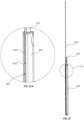
FIG. 19A is an enlarged view of the indicated area of detail ofFIG. 19 ; -
FIG. 20 is a perspective view of the inner cylindrical dilator ofFIG. 19 , illustrating advancement of the stimulation probe; -
FIG. 20A is an enlarged view of the indicated area of detail ofFIG. 20 ; -
FIG. 21 is a perspective view of the dilator assembly ofFIG. 11 , illustrating use with the stimulation probe; -
FIG. 21A is an enlarged view of the indicated area of detail ofFIG. 21 ; -
FIG. 22 is a perspective view of the dilator assembly ofFIG. 11 , illustrating advancement of the stimulation probe; -
FIG. 22A is an enlarged view of the indicated area of detail ofFIG. 22 ; -
FIG. 23 is a perspective view of the surgical retractor ofFIG. 1 , illustrating use with the dilator assembly ofFIG. 11 ; -
FIG. 24 is a perspective view of the surgical retractor ofFIG. 1 , illustrating use with an anterior arm; -
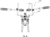
FIG. 25 is a top plan view of the surgical retractor ofFIG. 1 with manual blade assemblies; -
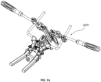
FIG. 26 is a perspective view of the surgical retractor with manual blade assemblies ofFIG. 25 ; -
FIG. 27 is a front view of the surgical retractor and manual blade assembly ofFIG. 25 ; -
FIG. 28 is an end view of the surgical retractor ofFIG. 1 with retractor blades in a first position; -
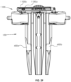
FIG. 29 is an end view of the surgical retractor ofFIG. 28 with the retractor blades in a second position; and -
FIG. 30 is an end view of the surgical retractor ofFIG. 28 , with the retractor blades in the second position and angled with respect to arms of the retractor. - Particular embodiments of the present disclosure are described hereinbelow with reference to the accompanying drawings; however, it is to be understood that the disclosed embodiments are merely exemplary of the disclosure and may be embodied in various forms. Well-known functions or constructions are not described in detail to avoid obscuring the present disclosure in unnecessary detail. Therefore, specific structural and functional details disclosed herein are not to be interpreted as limiting, but merely as a basis for the claims and as a representative basis for teaching one skilled in the art to variously employ the present disclosure in virtually any appropriately detailed structure. Like reference numerals refer to similar or identical elements throughout the description of the figures.
- As used herein, the term "distal" refers to that portion of the instrument, or component thereof which is farther from the user while the term "proximal" refers to that portion of the instrument or component thereof which is closer to the user. As used herein, the term "about" means that the numerical value is approximate and small variations would not significantly affect the practice of the disclosed embodiments.
- With initial reference to
FIGS. 1 and2 , a surgical retractor in accordance with an embodiment of the present disclosure is generally shown as asurgical retractor 100. Thesurgical retractor 100 may be utilized in accessing, e.g., lumbar vertebrae, using a trans-psoas approach. It is contemplated that thesurgical retractor 100 may be utilized in, e.g., discectomy, laminectomy, transforaminal or posterior lumbar interbody fusion (TLIF/PLIF), or posterior fixation (e.g., pedicle screw system). Thesurgical retractor 100 enables the surgeon to perform, e.g., an open procedure, in minimal space with reduced tissue damage. Thesurgical retractor 100 used in such procedures may reduce blood loss, improve recovery time, and/or reduce scarring. Thesurgical retractor 100 may be used as part of a lateral access surgical system including a dilator assembly 301 (FIG. 11 ) including an inner cylindrical dilator 200 (FIG. 12 ) and an outer triangular dilator 300 (FIG. 13 ), an intradiscal shim 600 (FIG. 14a ), a widening shim 700 (FIG. 16a ), a lengthening shim 800 (FIG. 18 ), an intradiscal guidewire 900 (FIG. 11a ), and a stimulation probe 1000 (FIG. 19 ), as will be described below. - With reference to
FIG. 1 , thesurgical retractor 100 includes atube assembly 110 and first andsecond retractor arms tube assembly 110. In particular, the first andsecond retractor arms tube assembly 110 about respective pivots "P1", "P2" such that distal ends of the respective first andsecond retractor arms FIG. 1 ) and a spaced part position (FIG. 2 ). - With particular reference to
FIG. 2 , thetube assembly 110 includes atube body 112 supporting arotatable knob 114 on aproximal end 112a thereof and a posteriorblade holder assembly 116 supported ondistal end 112b thereof. The posteriorblade holder assembly 116 includes ashaft arm assembly 116a, aposterior blade holder 116b supported on a distal end of theshaft arm assembly 116a, and aposterior blade 500 mounted on theposterior blade holder 116b. Theshaft arm assembly 116a is operatively coupled to therotatable knob 114 such that rotation of therotatable knob 114 in the direction of arrows "B" (about an axis "R1") causes axial displacement of theposterior blade holder 116b, and thus, theposterior blade 500 in the direction of arrows "A". In an embodiment, theshaft arm assembly 116a may include threads 117 that threadably engage thetube body 112. The threads 117 are disposed on lateral sides of theshaft arm assembly 116a to optimize load distribution. However, it is contemplated that the threads 117 may be disposed on top and bottom surfaces of theshaft arm assembly 116a. Under such a configuration, the clinician may position theposterior blade 500 at a desired position, e.g., away from thetube body 112. - With continued reference to
FIG. 2 , theposterior blade holder 116b includes aposterior blade seat 116c configured to, e.g., detachably, secure theposterior blade 500 thereto. For example, theposterior blade 500 may be detachably secured to theposterior blade seat 116c by a lockingscrew 116d. Alternatively, theposterior blade 500 may be detachably secured to theposterior blade holder 116b by, e.g., snap fit or friction fit. - In an embodiment, the
posterior blade 500 may be integrally formed with theposterior blade holder 116b as a single construct. Under such a configuration, the posteriorblade holder assembly 116 may be detachable from thetube body 112 or theshaft arm assembly 116a. Theposterior blade holder 116b further includes aposterior toeing screw 116e. Theposterior toeing screw 116e is rotatable to enable theposterior blade 500 to toe (i.e., angulate) relative to theshaft arm assembly 116a. For example, theposterior blade 500 may be rotated about an axis orthogonal to the length of theposterior blade 500 to angulate opposing ends of theposterior blade 500 in opposite directions in a range from about 0 degrees to about 30 degrees. Theposterior toeing screw 116e defines a cavity 119 having, e.g., a hex key feature, for non-slip engagement with a driving instrument to drive theposterior toeing screw 116e to cause toeing of theposterior blade 500. However, it is further contemplated that the cavity 119 may have any suitable configuration (e.g., slotted, hexagonal, square, etc.) for engagement with a complementary driving instrument. Under such a configuration, theposterior blade 500 is configured for selective axial displacement (towards and away from the tube body 112) and toeing (rotation about an axis orthogonal to the length of the posterior blade 500) by the clinician. - With reference to
FIGS. 5-7 , theposterior blade 500 has ablade body 502 including first andsecond rails inner surface 502a of theblade body 502 toengagement surfaces second rails second rails cutouts second rails inner surface 502a to define an openlongitudinal receiving trough 508 that is c-shaped for retaining an intradiscal shim 600 (FIGS. 14a and 14b ). The engagement surfaces 504a, 506a are configured to complement anouter surface 303 of an outer triangular dilator 300 (FIGS. 11 and13 ). The planarinner surface 502a defines arecess 502b in a proximal end portion thereof. The first andsecond rails cutouts longitudinal receiving trough 508 for limiting insertion depth or retraction of theintradiscal shim 600 relative to theposterior blade 500. Thecutouts intradiscal shim 600 at a fixed depth. Theblade body 502 also includes a mountinghook 512 supported on a proximal end thereof for securing theblade body 502 to theposterior blade seat 116c (FIG. 2 ) of theposterior blade holder 116b ofretractor 100. - With reference back to
FIGS. 1-4 , thetube assembly 110 further includes mountingwings tube assembly 110. The first andsecond retractor arms tube assembly 110 about the first and second pivots "P1" and "P2." Thefirst retractor arm 120 includes afirst handle portion 122, afirst blade holder 124, and a firstarm toeing base 123 configured to support thefirst blade holder 124 on thefirst retractor arm 120. Thefirst blade holder 124 is coupled to thefirst retractor arm 120 by afirst toeing screw 126 that is rotatable to enablefirst blade holder 124 to toe relative to firstarm toeing base 123 about toeing axis "T1" defined through thefirst retractor arm 120. Thefirst retractor arm 120 further supports afirst locking pawl 122a defining a ratchet mechanism with the mountingwing 118a, and thefirst drive pin 122b that secures thefirst retractor arm 120 to the mountingwing 118a of thetube assembly 110. Thefirst drive pin 122b defines a first pivot "P1" about which thefirst drive pin 122b rotates to pivot thefirst retractor arm 120 relative to thetube assembly 110 and thesecond retractor arm 130. Thefirst blade holder 124 further includes afirst blade seat 124a that supports afirst retractor blade 400a and afirst locking screw 124b to secure thefirst retractor blade 400a thereto such that thefirst retractor blade 400a may angulate with respect to the firstarm toeing base 123 when thefirst toeing screw 126 is rotated. - With continued reference to
FIGS. 1-4 , thesecond retractor arm 130, which mirrorsfirst retractor arm 120, includes asecond handle portion 132, asecond blade holder 134, and a secondarm toeing base 133 configured to support thesecond blade holder 134 on thesecond retractor arm 130. Thesecond retractor arm 130 supports asecond locking pawl 132a defining a ratchet mechanism with the mountingwing 118b, and asecond drive pin 132b that secures thesecond retractor arm 132 to the mountingwing 118b oftube assembly 110. Thesecond drive pin 132b defines a second pivot "P2" about which thesecond drive pin 132b rotates to pivot thesecond retractor arm 130 relative to thetube assembly 110 and thefirst retractor arm 120. Thesecond blade holder 134 further includes asecond blade seat 134a that supports asecond retractor blade 400b and asecond locking screw 134b to secure thesecond retractor blade 400b thereto so that thesecond retractor blade 400b can angulate with respect to the secondarm toeing base 133 when thesecond toeing screw 136 is rotated. With particular reference toFIG. 4 , in an embodiment, thetube assembly 110 may further include afirst table mount 119a coupled totube body 112 and asecond table mount 119b coupled toposterior blade holder 116b to mount thesurgical retractor 100 to a table. - It is contemplated that the first and second
arm toeing bases arm toeing base 123 is illustrated inFIGS. 4A-4D , however, the first and secondarm toeing bases arm toeing base 123 may be applied to the secondarm toeing base 133. In particular, the direction of layers of fiber incorporated into the base may define an angle β in the range of about 40 degrees and about 60 degrees, and preferably about 50 degrees, with respect to aleading edge 123 of the firstarm toeing base 123 in order to optimize the strength of the part relative to the directional forces experienced during use. Stated differently, the direction of layers of fiber may define the angle β with respect to an axis extending across thebore 127 configured to receive a screw 129 (FIG. 4 ) to secure the firstarm toeing base 123 and/or thefirst blade holder 124 to thefirst retractor arm 120. The use of thescrew 129 facilitates interchangeability of the firstarm toeing base 123 and thefirst blade holder 124 with the manual blade assembly 2000 (FIGS. 25-27 ) includingmanual blades 2100 manually movable on aretractor elbow rod 2500. As shown, the manual blade assembly may include rod-style arms attachable to and extending from the handle assembly. Blade assemblies may be attached to the rod-style arms at various locations, such as by a herth-style clamp. - With reference to
FIGS. 4E and 4F , it is further contemplated that the first andsecond blade holders first blade holder 124 is shown, however, the first andsecond blade holders first blade holder 124 may be applied to thesecond blade holder 134. In particular, the direction of layers of fiber may define an angle γ in the range of about 80 degrees and about 100 degrees, and preferably about 70 degrees, with respect to a trailingedge 125 of thefirst blade holder 124 in order to optimize the strength of the part relative to the directional forces experienced during use. The trailingedge 125 may be substantially parallel to an axis "P-P" defined by thebore 126 such that the direction of layers of fiber may define the angle γ with respect to axis "P-P". Under such a configuration, thefirst retractor arm 120 may be partially formed of a carbon fiber material. For example, thefirst blade holder 124 and thefirst toeing base 123 may be formed of a carbon fiber material and the rest of thefirst retractor arm 120 may be formed of stainless steel or aluminum or any other biocompatible material. The use of carbon fiber material for all or part of the toeingbases blade holders - With reference to
FIG. 4G , it is also contemplated that the posterior blade holder assembly 116 (also shown inFIG. 2 ) may be formed of a carbon fiber material to enhance structural integrity, reduce weight and improve visualization under imaging. In particular, the direction of layers of fiber may define an angle µ in the range of about 80 degrees and about 100 degrees with respect to a trailingedge 115 of the posteriorblade holder assembly 116. - With reference now to
FIGS. 8, 8A, 9 , and10 , the first andsecond retractor blades retractor blade body 402 having first andsecond rails inner surface 402a ofretractor blade body 402 toengagement surfaces second rails second rails cutouts second rails inner surface 402a to define an openlongitudinal receiving trough 408 that is, e.g., c-shaped, for retaining a widening shim 700 (FIG. 16a ) or lengthening shim 800 (FIG. 18 ).Engagement surfaces outer surface 303 of the outer triangular dilator 300 (FIGS. 11 and13 ). Theretractor blade body 402 further includes astop 410 disposed in the openlongitudinal receiving trough 408 adjacent a distal end portion of theretractor blade body 402 to limit distal movement of the widening shim 700 or the lengtheningshim 800 relative to theretractor blade body 402. The first andsecond rails notches longitudinal receiving trough 408 proximal to thestop 410 for locking the widening or lengtheningshims 700, 800 at a fixed depth relative toretractor blade body 402. Theretractor blade body 402 also includes a mountinghook 412 supported on a proximal end thereof for securing theretractor blade body 402 to the first orsecond blade seats FIG. 2 ) of the respective first andsecond retractor arms posterior blade 500 and the first andsecond retractor blades posterior blade 500, thefirst retractor blade 400a, or thesecond retractor blade 400b, in order to enhance structural integrity of the component and visualization of the orientation and position of the retractor relative to the patient when viewed under imaging such as fluoroscopy. For example, the direction of layers of carbon fiber may define an angle α in the range of about 80 degrees and about 100 degrees, and preferably about 70 degrees, with respect to a trailingedge 401 of the first orsecond retractor blades posterior blade 500 and the first andsecond retractor blades blade holders blade holder assembly 116. In this manner, the surgeon advantageously may orient the retractor blades in the posterior, position relative to the operative site and patient anatomy, thereby providing maximum flexibility of use of the retractor and directions of motion of the blades during adjustment. In addition, it is contemplated that the various shims disclosed herein may be formed of titanium. - With reference to
FIGS. 11-13 , adilator assembly 301 including an innercylindrical dilator 200 and an outertriangular dilator 300 may be used in conjunction with thesurgical retractor 100 during a surgical procedure. The innercylindrical dilator 200 may include acylindrical body 202 formed of a suitable biocompatible material such as, e.g., aluminum, that defines a circular cross-sectional outer profile. The innercylindrical dilator 200 also defines aguidewire passage 202a that extends through a length of thecylindrical body 202 for receiving anintradiscal guidewire 900 therein. Thecylindrical body 202 defines aninsert window 202b through asidewall 202c ofcylindrical body 202 at a distal end portion ofcylindrical body 202. Theinsert window 202b is positioned to receive aninsert 206 of the innercylindrical dilator 200 therethrough such that thecylindrical body 202 of innercylindrical dilator 200 may support theinsert 206 therein. Thecylindrical body 202 further defines apin hole 202d transverse to theinsert window 202b for receiving apin 208 of the innercylindrical dilator 200 therein to pin theinsert 206 to thecylindrical body 202. Thecylindrical body 202 further includes anopen side channel 202e that extends along a length of an outer surface ofcylindrical body 202 into theinsert window 202b. Theinsert 206 also includes anopen side channel 206a that extends along an outer surface of theinsert 206 and is disposed in registration withopen side channel 202e ofcylindrical body 202 while theinsert 206 is pinned tocylindrical body 202. Theopen side channel 206a of theinsert 206 extends to adistal abutment 206b that inhibits a stimulation probe 1000 (FIG. 20 ) from advancing distally beyond thedistal abutment 206b (i.e., a depth or limit stop) whenstimulation probe 1000 is selectively advanced along theopen side channel 206a of theinsert 206. - With particular reference to
FIGS. 11 and13 , an outertriangular dilator 300 for use with thesurgical retractor 100 has atriangular body 302 with anouter surface 303 having three planarouter sides planar side triangular dilator 300 may be about 10 mm. However, when thetriangular dilator 300 is rotated, a point where two of theplanar sides triangular body 302 defines aninner dilator passage 304 longitudinally therethrough. Thetriangular body 302 further defines anopen side channel 306 along theouter surface 303 of thetriangular body 302 that extends to adistal abutment 306a (FIG. 22 ) that inhibits the stimulation probe 1000 (FIG. 22 ) from advancing distally beyonddistal abutment 306a (i.e., a depth or limit stop) whenstimulation probe 1000 is selectively advanced alongopen side channel 306. The triangular cross-sectional shape of the outer dilator advantageously requires a reduced cross-sectional area relative to a corresponding circular cross-section, thereby potentially reducing trauma to tissue and decreasing insertion force during insertion. The triangular shape also provides positive orientation of the retractor and the outer dilator during insertion. - With reference now to
FIGS. 13a, 13b ,14a, 14b , and15 , theintradiscal shim 600 includes ashim body 602 that extends distally to apointed tip 604 and includes a pair offlexible arms 606 that extend proximally from theshim body 602 and includenubs 606a that extend laterally therefrom for engaging thecutouts posterior blade 500 to fix a position of theintradiscal shim 600 relative toposterior blade 500. Theshim body 602 has planar front and rear surfaces and further includes aflexible finger 608 having anengagement tooth 608a projecting rearwardly therefrom. It is contemplated that theshim body 602 may define an opening 607 (FIGS. 13a and 13b ) that may be used during an imaging process to indicate relative position of theshim body 602 with respect to theposterior blade 500. Thus, when the shim is fully deployedopening 607 will appear below the bottom edge of the blade when viewed under imaging. - With reference to
FIGS. 8 ,16a , and16b , wideningshims bodies body 702a has alip 703a on a left side thereof and the wideningbody 702b has alip 703b on a right side thereof. Each of the wideningshims flexible arms 704 that extend proximally from aprojection 706 that extends rearwardly from the respective wideningbodies projection 706 includes anose 706a positioned to engage thestop 410 of theretractor blade body 402 of one of the first andsecond retractor blades shim retractor blade body 402 of one of the first andsecond retractor blades flexible arms 704 includenubs 704a that are configured to secure the respective wideningshims notches retractor blade body 402 for limiting insertion depth of the respective wideningshims retractor blade body 402. The wideningshims second retractor blades second retractor blades shims second retractor blades - With reference now to
FIGS. 8 ,17a ,17b , and18 , a lengtheningshim 800 may be used with the first andsecond retractor blades shim 800 includes a lengtheningbody 802 with, e.g., a curvilinear profile, and anupper portion 802a and alower portion 802b that are selectively movable relative to one another (in the direction of arrows "Z") in response to rotation of a lengthening screw 803 (in the direction of arrows "Y") threadably coupled to the upper andlower portions upper portion 802a includes distally-extendinglegs 805 that are slidably received withinleg lumens 807 defined in thelower portion 802b. The lengtheningshim 800 further includes a pair offlexible arms 806 that extend proximally from aprojection 808 that extends rearwardly from the lengtheningbody 802. Theprojection 808 includes anose 808a that is positioned to engage thestop 410 of theretractor blade body 402 of one of the first andsecond retractor blades shim 800 relative to theretractor blade body 402 of one of the first andsecond retractor blades flexible arms 806 are configured to secure the lengtheningshim 800 to thenotches retractor blade body 402 for limiting insertion depth of lengtheningshim 800 relative toretractor blade body 402. - In use, a patient may be placed in a lateral decubitus position on a patient table. At this time, one or more skin incisions are made at the appropriate operative level so that subcutaneous tissue layers are taken down to expose the oblique fascia. The muscle fibers are separated as a finger is advanced into the retroperitoneal space. The peritoneum is safely released anteriorly as the retroperitoneal space is further developed. Finger palpation of the psoas muscle or the anterior tip of the transverse process is used to confirm proper location. Once verified, the inner
cylindrical dilator 200 is introduced into the prepared path and advanced through the psoas muscle. Staying anterior to the lumbar plexus, the innercylindrical dilator 200 is docked directly onto the disc. The intradiscal guidewire 900 is placed through the innercylindrical dilator 200 and advanced into the disc, approximately halfway across the disc space as indicated through anteroposterior fluoroscopy. Additional soft tissue dilation is then performed with the outertriangular dilator 300 being advanced over theguidewire 900 and the innercylindrical dilator 200 so thatintradiscal guidewire 900 and the innercylindrical dilator 200 are received through theinner dilator passage 304 of the outer triangular dilator 300 (FIG. 5 ). After an adequate path to the spine is prepared, blade length of the first andsecond retractor blades posterior blade 500 may be determined by markings located on the outertriangular dilator 300 in relation to the skin level. The first andsecond retractor blades posterior blade 500 are available from about 80 to about 180 mm in, e.g., 10 mm, increments. - With reference to
FIGS. 19-22 , if a surgeon elects to utilize neuromonitoring,open side channels cylindrical dilator 200 and theinsert 206 oropen side channel 306 along the outer surface oftriangular body 302, can be utilized to receive astimulation probe 1000 for advancingstimulation probe 1000 relative to the innercylindrical dilator 200 and the outertriangular dilator 300. When thestimulation probe 1000 is fully seated in innercylindrical dilator 200, adistal tip 1002 ofstimulation probe 1000 engages thedistal abutment 206b. When thestimulation probe 1000 is fully seated in the outertriangular dilator 300, the distal tip 102 of thestimulation probe 1000 engages thedistal abutment 306a. - Once blade length is determined, the first and
second retractor blades posterior blade 500 are mounted to thesurgical retractor 100 and locked thereto via lockingscrews surgical retractor 100. The surgeon may elect to use blades made of metal (e.g., aluminum) or a carbon fiber material and have such blades attached to the retractor blade holders. In particular, the first andsecond retractor blades second retractor arms posterior blade 500 is mounted to the posteriorblade holder assembly 116. As pointed out above, however, different blade mounting orientations are permitted, if desired. If using theintradiscal shim 600, theintradiscal shim 600 is positioned within the openlongitudinal receiving trough 508 ofposterior blade 500 without being deployed past a distal end ofposterior blade 500 prior to blade insertion into tissue (FIG. 15 ). Once theengagement tooth 608a of theintradiscal shim 600 is advanced through the openlongitudinal receiving trough 508 past therecess 502b of theposterior blade 500, proximal movement of theintradiscal shim 600 causes theengagement tooth 608a to engage therecess 502b of theposterior blade 500 so that theintradiscal shim 600 cannot be removed fromposterior blade 500 while theposterior blade 500 is secured to theretractor 100 as access to therecess 502b is only possible when theposterior blade 500 is removed from theretractor 100. - The first and
second retractor arms second retractor arms outer surface 303 of the outertriangular dilator 300 so thatfirst retractor blade 400a is spaced fromsecond retractor blade 400b by, e.g., about 1 mm (FIG. 28 ). The first andsecond retractor arms second retractor arms rotatable knob 114 is also rotated in a first direction to translate the posteriorblade holder assembly 116 distally away from thetube assembly 110 of thesurgical retractor 100 until theposterior blade 500 engages the outertriangular dilator 300 and is disposed in close approximation with the first andsecond retractor blades second retractor blades posterior blade 500 define a triangular opening around the outertriangular dilator 300. The triangular opening provides a reduced surface area compared to, e.g., a circular opening, which may reduce tissue trauma, as well as resistance to dilation during advancement. Therotatable knob 114 can also be rotated in a second direction to translate the posteriorblade holder assembly 116 proximally toward thetube assembly 110 as desired. - With reference now to
FIG. 23 , the first andsecond retractor blades posterior blade 500 can then be advanced down the outertriangular dilator 300 into the tissue to engage the spine "S" with the first andsecond handle portions second retractor arms retractor blades posterior blade 500 seated onto the disc space and properly aligned in lateral and anteroposterior views is verified. Use of carbon fiber materials may improve visualization of the orientation and position of the retractor relative to the patient when viewed under imaging such as fluoroscopy. Thesurgical retractor 100 can then be secured via first and/or second table mounts 119a, 119b using a table mount attachment (not shown). - After the
posterior blade 500 is determined to be positioned away from surrounding neurological structures, using a shim adjuster (not shown), theintradiscal shim 600 can be deployed relative to theposterior blade 500 into the disc space to a desired depth and secured to theposterior blade 500 via flexible arms 606 (FIG. 13b ). Under imaging such asfluoroscopic imaging hole 607 will be visible beyond the tip of the blade when the shim is fully deployed. - Each of the first and
second retractor blades posterior blade 500 can be independently manipulated to expand the operative corridor (FIG. 4 ). With reference toFIGS. 1-4 , to move the first andsecond retractor arms second retractor arms second handle portions second retractor arms second retractor blades second retractor arms 120, 130 (FIG. 30 ). To move theposterior blade 500 away from the first andsecond retractor blades blade holder assembly 116 can be translated proximally towardtube assembly 110 by rotating the rotatable knob 114 (FIG. 29 ). Referring now toFIGS. 28-30 , ananterior arm 1100 advantageously is designed and constructed to allow sliding movement of oneend 1100a of theanterior arm 1100 relative to across-connecting arm portion 1100b. In this manner, theanterior arm 1100, with or without blade 1200 (FIG. 24 ) attached to theanterior arm 1100, may be permitted to lengthen or shorten during adjustment of the first andsecond retractor arms retractor arms second retractor arms anterior arm 1100 or theanterior blade 1200. It is also contemplated that a locking mechanism may be provided to lock theanterior arm 1100 in position and prevent sliding adjustment of the arm when the locking mechanism is engaged. - Once the
surgical retractor 100 is fixed in a desired position, the innercylindrical dilator 200 and the outertriangular dilator 300 can be removed from the assembly to expose the operative site. A bifurcated reusable light source (not shown) can be utilized for lighting the operative corridor. If additional retraction is desired, ananterior arm 1100 andblade 1200 can be mounted to theretractor 100 as shown inFIG. 24 . - While various embodiments of the present disclosure have been shown and described herein, it will be obvious to those skilled in the art that these embodiments are provided by way of example only. Numerous variations, changes, and substitutions will now occur to those skilled in the art without departing from the present disclosure. Accordingly, it is intended that the invention be limited only by the scope of the appended claims.
Claims (14)
- A surgical retractor (100) comprisinga body portion including:a first blade holder (116) and a first blade (500) detachably secured to the first blade holder; andfirst and second retractor arms (120, 130) operatively coupled to the body portion, characterized in that:the body portion comprises:
a tube assembly (110) comprising:a rotatable knob (114);the first blade holder (116) operatively coupled with the rotatable knob such that rotation of the rotatable knob causes axial displacement of the first blade holder;the first blade being configured for axial displacement with the first blade holder and angulation relative to at least part of the body portion about a first toeing axis; andfirst and second mounting wings (118a, 118b) extending from opposing sides of the tube assembly (110);a first drive pin (122b) securing the first retractor arm to the first mounting wing, the first drive pin defining a first pivot axis (P 1) about which the first drive pin rotates to pivot the first retractor arm relative to the tube assembly and the second retractor arm; anda second drive pin (132b) securing the second retractor arm to the second mounting wing, the second drive pin defining a second pivot axis (P2) about which the second drive pin rotates to pivot the second retractor arm relative to the tube assembly and the first retractor arm;the first and second retractor arms including respective second and third blades (400a, 400b) detachably secured thereto, the first and second retractor arms transitionable between an approximated configuration in which the second and third blades are proximate each other, and a spaced apart configuration in which the second and third blades are spaced apart from each other, the second and third blades being further configured to angulate about respective second and third toeing axes (T 1, T2) that are defined by the respective first and second retractor arms. - The surgical retractor according to claim 1, wherein at least a portion of the first retractor arm, the second retractor arm, the first blade, the second blade or the third blade is made of a carbon fiber material.
- The surgical retractor according to any one of claims 1-2, wherein the first blade is configured for axial displacement independent of the angulation thereof.
- The surgical retractor according to any one of claims 1-3, wherein the first blade is configured to angulate about the first axis orthogonal to a longitudinal axis defined by the body portion.
- The surgical retractor according to any one of claims 1-4, wherein the first and second retractor arms includes a ratchet mechanism (122a, 132a) to adjust and maintain respective relative positions of the first and second retractor arms with respect to the body portion.
- The surgical retractor according to any one of claims 1-5, wherein the first or second retractor arm includes a handle portion (122, 132), an arm toeing base (123, 133), and a blade holder (124, 134) configured to secure the corresponding second or third blade thereto, the blade holder coupled to the arm toeing base by a toeing screw (126, 136) that is rotatable to enable the blade holder to rotate relative to the arm toeing base.
- The surgical retractor according to any one of claims 1-6, wherein the first, second, and third blades are configured to define a triangular shaped cavity when proximate each other.
- The surgical retractor according to any one of claims 1-7, wherein the first blade has a first inner surface and the second and third blades have a second inner surface different from the first inner surface.
- The surgical retractor according to any one of claims 1-8, wherein the first blade includes a first rail (504), a second rail (506) and a longitudinal receiving trough (508) in between the first and second rails, the first blade configured to support an intradiscal shim (600, 700, 800).
- The surgical retractor according to claim 9, wherein the first rail includes a first cutout (504c) and the second rail includes a second cutout (506c), the first and second cutouts being configured to lock the intradiscal shim relative to the first blade.
- The surgical retractor according to claim 10, wherein the first rail includes a third cutout (504c) and the second rail includes a fourth cutout (506c), the third cutout being different in shape from the first cutout.
- The surgical retractor according to any one of claims 1-11, wherein the first and second retractor arms are in the approximated configuration, the second and third blades define a gap of about 1 mm.
- The surgical retractor according to any one of claims 1-12, wherein the body portion further comprises a tube assembly (110) and a shaft arm assembly (116a) extending from the tube assembly, the first blade holder being attached to an end of the shaft arm assembly opposite the tube assembly, the shaft arm assembly being translatable in predetermined increments relative to the tube assembly to cause axial displacement of the first blade holder.
- The surgical retractor according to claim 13, wherein the body portion includes a toeing screw (116e) adjacent to the first blade holder such that rotation of the toeing screw causes the first blade holder to rotate relative to the shaft arm assembly.
Applications Claiming Priority (2)
| Application Number | Priority Date | Filing Date | Title |
|---|---|---|---|
| US201962941096P | 2019-11-27 | 2019-11-27 | |
| US16/832,599 US11564674B2 (en) | 2019-11-27 | 2020-03-27 | Lateral access system and method of use |
Publications (2)
| Publication Number | Publication Date |
|---|---|
| EP3847974A1 EP3847974A1 (en) | 2021-07-14 |
| EP3847974B1 true EP3847974B1 (en) | 2024-07-31 |
Family
ID=75974578
Family Applications (1)
| Application Number | Title | Priority Date | Filing Date |
|---|---|---|---|
| EP20210090.5A Active EP3847974B1 (en) | 2019-11-27 | 2020-11-26 | Lateral access system |
Country Status (2)
| Country | Link |
|---|---|
| US (1) | US11564674B2 (en) |
| EP (1) | EP3847974B1 (en) |
Families Citing this family (3)
| Publication number | Priority date | Publication date | Assignee | Title |
|---|---|---|---|---|
| US11944286B2 (en) * | 2020-01-24 | 2024-04-02 | Lsi Solutions, Inc. | Surgical rib retractor |
| US20240065680A1 (en) * | 2022-08-30 | 2024-02-29 | Warsaw Orthopedic, Inc. | Tissue retractor having operative corridor formed by dilator and blades |
| US12390206B2 (en) | 2022-11-30 | 2025-08-19 | Thompson Surgical Instruments, Inc. | Compressor/distractor with tower traversal |
Family Cites Families (399)
| Publication number | Priority date | Publication date | Assignee | Title |
|---|---|---|---|---|
| US380745A (en) | 1888-04-10 | Speculum | ||
| US447761A (en) | 1891-03-10 | Speculum | ||
| US1618261A (en) | 1927-02-22 | Viscera retainer for use in abdominal operations | ||
| US832201A (en) | 1904-12-12 | 1906-10-02 | Samuel L Kistler | Dilator. |
| US1157202A (en) | 1913-10-14 | 1915-10-19 | Uri C Bates | Surgical apparatus. |
| US1428653A (en) | 1920-06-10 | 1922-09-12 | Nick Peter | Dilator combination |
| US1827497A (en) | 1929-05-22 | 1931-10-13 | Varney William Thomas | Speculum |
| US1863057A (en) | 1930-03-03 | 1932-06-14 | George A Innes | Surgical drain |
| US1839726A (en) | 1930-08-01 | 1932-01-05 | Hubert R Arnold | Circular retractor |
| US1944009A (en) | 1932-06-14 | 1934-01-16 | Ralph W Homer | Intra-abdominal retractor |
| US2313164A (en) | 1939-11-13 | 1943-03-09 | Walfred A Nelson | Self-retaining surgical retractor |
| US2586488A (en) | 1949-05-11 | 1952-02-19 | David P Smith | Table supported surgical retractor |
| US2812758A (en) | 1955-07-26 | 1957-11-12 | John C Blumenschein | Surgical retractor |
| US2854983A (en) | 1957-10-31 | 1958-10-07 | Arnold M Baskin | Inflatable catheter |
| US3000782A (en) | 1958-04-18 | 1961-09-19 | Royal Bond Inc | Materials for embalming human corpses |
| US3087486A (en) | 1959-03-05 | 1963-04-30 | Cenco Instr Corp | Cardiac electrode means |
| US3010180A (en) | 1959-04-08 | 1961-11-28 | Hoffman Maufred Turner | Method for manufacturing non-woven pile fabrics |
| US3005535A (en) | 1959-12-23 | 1961-10-24 | Electric Storage Battery Co | Automatic transfer machine |
| US3070088A (en) | 1961-02-02 | 1962-12-25 | Brahos Nicholas George | Surgical retractor device |
| US3221743A (en) | 1962-08-13 | 1965-12-07 | Pa Co Inc Du | System and apparatus for positioning and securing surgical implements |
| US3394700A (en) | 1965-12-24 | 1968-07-30 | Yamamoto Hideo | Circular surgical retractor apparatus |
| US3397699A (en) | 1966-05-05 | 1968-08-20 | Gerald C. Kohl | Retaining catheter having resiliently biased wing flanges |
| US3522799A (en) | 1967-06-21 | 1970-08-04 | William K Gauthier | Surgical retractor device |
| US3509883A (en) | 1967-11-29 | 1970-05-05 | Gen Electric | Expanding cannula |
| US3417746A (en) | 1968-02-27 | 1968-12-24 | Welch Allyn Inc | Illuminating endoscope with disposable elements |
| US3731673A (en) | 1971-03-29 | 1973-05-08 | W Halloran | Self-retaining muscle retractor |
| US3770342A (en) | 1971-05-07 | 1973-11-06 | R Dudragne | Device for lighting and examining a cavity |
| US3749088A (en) | 1971-06-23 | 1973-07-31 | W Kohlmann | Surgical retractor device |
| US3807393A (en) | 1972-03-01 | 1974-04-30 | Donald B Mc | Surgical retractor |
| US3789852A (en) | 1972-06-12 | 1974-02-05 | S Kim | Expandable trochar, especially for medical purposes |
| US3788318A (en) | 1972-06-12 | 1974-01-29 | S Kim | Expandable cannular, especially for medical purposes |
| US3782370A (en) | 1972-07-12 | 1974-01-01 | B Mcdonald | Surgical retractor |
| US3944341A (en) | 1972-09-25 | 1976-03-16 | Retina Foundation | Wide-angle ophthalmoscope and fundus camera |
| US3796214A (en) | 1972-12-04 | 1974-03-12 | R Davis | Perineal retractor |
| US3965890A (en) | 1974-10-18 | 1976-06-29 | William Kohlmann Gauthier | Surgical retractor |
| US3998217A (en) | 1975-01-13 | 1976-12-21 | William E. Trumbull | Surgical retractor device |
| US4010741A (en) | 1976-01-22 | 1977-03-08 | William Kohlmann Gauthier | Surgical retractor |
| US4130113A (en) | 1976-12-15 | 1978-12-19 | Richards Manufacturing Co., Inc. | Retractor |
| US4141364A (en) | 1977-03-18 | 1979-02-27 | Jorge Schultze | Expandable endotracheal or urethral tube |
| US4226228A (en) | 1978-11-02 | 1980-10-07 | Shin Hee J | Multiple joint retractor with light |
| US4254763A (en) | 1979-06-07 | 1981-03-10 | Codman & Shurtleff, Inc. | Surgical retractor assembly |
| US4337763A (en) | 1980-04-21 | 1982-07-06 | The United States Of America As Represented By The Department Of Health, Education And Welfare | Illuminated surgical instrument |
| US4312353A (en) | 1980-05-09 | 1982-01-26 | Mayfield Education And Research Fund | Method of creating and enlarging an opening in the brain |
| US4545374A (en) | 1982-09-03 | 1985-10-08 | Jacobson Robert E | Method and instruments for performing a percutaneous lumbar diskectomy |
| US4589868A (en) | 1984-03-12 | 1986-05-20 | Dretler Stephen P | Expandable dilator-catheter |
| DE3509787C2 (en) | 1984-04-04 | 1987-03-19 | Aesculap-Werke Ag Vormals Jetter & Scheerer, 7200 Tuttlingen | Surgical instrument for spreading wound edges |
| GB8424436D0 (en) | 1984-09-27 | 1984-10-31 | Pratt Int Ltd Burnerd | Surgical appliance |
| US4718151A (en) | 1984-11-08 | 1988-01-12 | Minnesota Scientific, Inc. | Retractor apparatus |
| US4949707A (en) | 1984-11-08 | 1990-08-21 | Minnesota Scientific, Inc. | Retractor apparatus |
| US4617916A (en) | 1984-11-08 | 1986-10-21 | Minnesota Scientific, Inc. | Retractor apparatus |
| US4733665C2 (en) | 1985-11-07 | 2002-01-29 | Expandable Grafts Partnership | Expandable intraluminal graft and method and apparatus for implanting an expandable intraluminal graft |
| US4813401A (en) | 1986-11-26 | 1989-03-21 | Grieshaber Manufacturing Company | Retractor |
| US4779611A (en) | 1987-02-24 | 1988-10-25 | Grooters Ronald K | Disposable surgical scope guide |
| US4817587A (en) | 1987-08-31 | 1989-04-04 | Janese Woodrow W | Ring para-spinal retractor |
| US5772661A (en) | 1988-06-13 | 1998-06-30 | Michelson; Gary Karlin | Methods and instrumentation for the surgical correction of human thoracic and lumbar spinal disease from the antero-lateral aspect of the spine |
| US6120437A (en) | 1988-07-22 | 2000-09-19 | Inbae Yoon | Methods for creating spaces at obstructed sites endoscopically and methods therefor |
| US5052373A (en) | 1988-07-29 | 1991-10-01 | Michelson Gary K | Spinal retractor |
| US4896669A (en) | 1988-08-31 | 1990-01-30 | Meadox Medicals, Inc. | Dilatation catheter |
| US4971037A (en) | 1988-09-19 | 1990-11-20 | Pilling Co. | Surgical retractor support |
| US5032113A (en) | 1989-04-13 | 1991-07-16 | Scimed Life Systems, Inc. | Innerless catheter |
| US4971038A (en) | 1989-04-26 | 1990-11-20 | Farley Daniel K | Table mounted surgical retractor |
| US5116318A (en) | 1989-06-06 | 1992-05-26 | Cordis Corporation | Dilatation balloon within an elastic sleeve |
| GB2240926A (en) | 1990-02-14 | 1991-08-21 | Steven Streatfield Gill | An expansible cannula |
| US5331975A (en) | 1990-03-02 | 1994-07-26 | Bonutti Peter M | Fluid operated retractors |
| US5514153A (en) | 1990-03-02 | 1996-05-07 | General Surgical Innovations, Inc. | Method of dissecting tissue layers |
| US6277136B1 (en) | 1990-03-02 | 2001-08-21 | General Surgical Innovations, Inc. | Method for developing an anatomic space |
| US5954739A (en) | 1990-03-02 | 1999-09-21 | General Surgical Innovations, Inc. | Method of dissecting tissue layers |
| US5163949A (en) | 1990-03-02 | 1992-11-17 | Bonutti Peter M | Fluid operated retractors |
| US5454365A (en) | 1990-11-05 | 1995-10-03 | Bonutti; Peter M. | Mechanically expandable arthroscopic retractors |
| US5092314A (en) | 1990-05-08 | 1992-03-03 | Zeitels Steven M | Adjustable supraglottiscope and methods therefor |
| US5183464A (en) | 1991-05-17 | 1993-02-02 | Interventional Thermodynamics, Inc. | Radially expandable dilator |
| US5383889A (en) | 1991-05-29 | 1995-01-24 | Origin Medsystems, Inc. | Tethered everting balloon retractor for hollow bodies and method of using |
| EP0637223B1 (en) | 1991-05-29 | 1998-07-22 | Origin Medsystems, Inc. | Retraction apparatus for endoscopic surgery |
| US5707362A (en) | 1992-04-15 | 1998-01-13 | Yoon; Inbae | Penetrating instrument having an expandable anchoring portion for triggering protrusion of a safety member and/or retraction of a penetrating member |
| US6540764B1 (en) | 1992-06-02 | 2003-04-01 | General Surgical Innovations, Inc. | Apparatus and method for dissecting tissue layers |
| US6312442B1 (en) | 1992-06-02 | 2001-11-06 | General Surgical Innovations, Inc. | Method for developing an anatomic space for laparoscopic hernia repair |
| US5540711A (en) | 1992-06-02 | 1996-07-30 | General Surgical Innovations, Inc. | Apparatus and method for developing an anatomic space for laparoscopic procedures with laparoscopic visualization |
| GR930100244A (en) | 1992-06-30 | 1994-02-28 | Ethicon Inc | Flexible endoscopic surgical port |
| US5312417A (en) | 1992-07-29 | 1994-05-17 | Wilk Peter J | Laparoscopic cannula assembly and associated method |
| US5351679A (en) | 1992-08-17 | 1994-10-04 | Ilya Mayzels | Surgical endoscopic retractor instrument |
| US5580344A (en) | 1992-10-22 | 1996-12-03 | Hasson; Harrith M. | Incision converter & method of using the same |
| US5377667A (en) | 1992-12-03 | 1995-01-03 | Michael T. Patton | Speculum for dilating a body cavity |
| US5320611A (en) | 1993-02-04 | 1994-06-14 | Peter M. Bonutti | Expandable cannula having longitudinal wire and method of use |
| US5961499A (en) | 1993-02-04 | 1999-10-05 | Peter M. Bonutti | Expandable cannula |
| US6338730B1 (en) | 1993-02-04 | 2002-01-15 | Peter M. Bonutti | Method of using expandable cannula |
| JPH08502438A (en) | 1993-02-22 | 1996-03-19 | ヴァリーラブ・インコーポレーテッド | Laparoscopic distraction tension retractor device and method |
| DK171747B1 (en) | 1993-03-02 | 1997-05-05 | Metra Aps | dilatation catheter |
| US5431676A (en) | 1993-03-05 | 1995-07-11 | Innerdyne Medical, Inc. | Trocar system having expandable port |
| US5755661A (en) | 1993-06-17 | 1998-05-26 | Schwartzman; Alexander | Planar abdominal wall retractor for laparoscopic surgery |
| US5957832A (en) | 1993-10-08 | 1999-09-28 | Heartport, Inc. | Stereoscopic percutaneous visualization system |
| US5512038A (en) | 1993-11-15 | 1996-04-30 | O'neal; Darrell D. | Spinal retractor apparatus having a curved blade |
| US5520611A (en) | 1993-12-16 | 1996-05-28 | Rao; Shekar | Illuminated retractor |
| ATE293395T1 (en) | 1994-01-26 | 2005-05-15 | Kyphon Inc | IMPROVED INFLATABLE DEVICE FOR USE IN SURGICAL PROTOCOLS RELATING TO BONE FIXATION |
| US5391178A (en) | 1994-02-14 | 1995-02-21 | Yapor; Wesley | Cerebral dilator |
| US5425730A (en) | 1994-02-16 | 1995-06-20 | Luloh; K. P. | Illumination cannula system for vitreous surgery |
| US5897087A (en) | 1994-03-15 | 1999-04-27 | Thompson Surgical Instruments, Inc. | CAM tightened universal joint clamp |
| US5452732A (en) | 1994-04-26 | 1995-09-26 | Bircoll; Mel | Method of dissecting along connective tissue lines |
| US5460170A (en) | 1994-08-23 | 1995-10-24 | Hammerslag; Julius G. | Adjustable surgical retractor |
| US5702419A (en) | 1994-09-21 | 1997-12-30 | Wake Forest University | Expandable, intraluminal stents |
| US5697946A (en) | 1994-10-07 | 1997-12-16 | Origin Medsystems, Inc. | Method and apparatus for anchoring laparoscopic instruments |
| US5653726A (en) | 1994-11-03 | 1997-08-05 | Archimedes Surgical, Inc. | Retrograde dissector and method for facilitating a TRAM flap |
| IT232096Y1 (en) | 1994-11-29 | 1999-08-16 | Soriani & Moser Manufacturers | CAROUSEL OF FUN PERFECTED |
| US5678572A (en) | 1995-01-12 | 1997-10-21 | Shaw; Dein | Cavity expanding device for laparoscopic surgery |
| US5916151A (en) | 1995-03-07 | 1999-06-29 | Charters; John Dumergue | Apparatus for dilating a body cavity |
| US5607441A (en) | 1995-03-24 | 1997-03-04 | Ethicon Endo-Surgery, Inc. | Surgical dissector |
| US5702417A (en) | 1995-05-22 | 1997-12-30 | General Surgical Innovations, Inc. | Balloon loaded dissecting instruments |
| US5944734A (en) | 1995-05-22 | 1999-08-31 | General Surgical Innovations, Inc. | Balloon dissecting instruments |
| US5993472A (en) | 1995-05-22 | 1999-11-30 | General Surgical Innovations, Inc. | Balloon dissecting instruments |
| US5893866A (en) | 1995-05-22 | 1999-04-13 | General Surgical Innovations, Inc. | Balloon dissecting instruments |
| US6004340A (en) | 1995-05-22 | 1999-12-21 | General Surgical Innovations, Inc. | Balloon dissecting instruments |
| US6027518A (en) | 1995-05-30 | 2000-02-22 | Gaber; Benny | Seizing instrument |
| DE29510204U1 (en) | 1995-06-23 | 1995-08-31 | Aesculap Ag, 78532 Tuttlingen | Surgical retractor |
| US5688223A (en) | 1995-11-08 | 1997-11-18 | Minnesota Scientific, Inc. | Retractor support with adjustable retractor blades |
| US5882334A (en) | 1995-12-04 | 1999-03-16 | Target Therapeutics, Inc. | Balloon/delivery catheter assembly with adjustable balloon positioning |
| ATE347311T1 (en) | 1996-03-20 | 2006-12-15 | Gen Surgical Innovations Inc | COMBINED DISSECTION AND RETRACTION DEVICE |
| US6013083A (en) | 1997-05-02 | 2000-01-11 | Bennett; William F. | Arthroscopic rotator cuff repair apparatus and method |
| US5827319A (en) | 1996-05-20 | 1998-10-27 | Innerdyne, Inc. | Radially expandable access system having disposable and reusable components |
| US6431025B1 (en) | 1996-08-30 | 2002-08-13 | Tibor Koros | Ratchet mechanism for a surgical retractor assembly |
| US6464697B1 (en) | 1998-02-19 | 2002-10-15 | Curon Medical, Inc. | Stomach and adjoining tissue regions in the esophagus |
| US6322500B1 (en) | 1996-12-23 | 2001-11-27 | University Of Massachusetts | Minimally invasive surgical apparatus |
| US5919128A (en) | 1997-06-18 | 1999-07-06 | The Regents Of The University Of California | Sparse aperture endoscope |
| US5888197A (en) | 1997-07-01 | 1999-03-30 | Thompson Surgical Instruments, Inc. | Cam-operated universal latch joint apparatus |
| US5944658A (en) | 1997-09-23 | 1999-08-31 | Koros; Tibor B. | Lumbar spinal fusion retractor and distractor system |
| US5967970A (en) | 1997-09-26 | 1999-10-19 | Cowan; Michael A. | System and method for balloon-assisted retraction tube |
| DE69837611T2 (en) | 1997-10-01 | 2007-12-27 | Boston Scientific Ltd., St. Michael | dilation |
| FR2770124B1 (en) | 1997-10-23 | 1999-12-10 | Materiel Orthopedique En Abreg | SURGICAL INSTRUMENTATION FOR SHRINKAGE AND SPREADING OF SOFT TISSUES AND VESSELS FOR AN ANTERIOR APPROACH OF THE RACHIS |
| US6206826B1 (en) | 1997-12-18 | 2001-03-27 | Sdgi Holdings, Inc. | Devices and methods for percutaneous surgery |
| US6387095B1 (en) | 1998-02-09 | 2002-05-14 | Loren R. Kennett | Surgical device comprising a radially expandable non-conductive sheath |
| AUPP294698A0 (en) | 1998-04-15 | 1998-05-07 | Gray, Bruce | Removable ball joint |
| US6354995B1 (en) | 1998-04-24 | 2002-03-12 | Moshe Hoftman | Rotational lateral expander device |
| US5928139A (en) | 1998-04-24 | 1999-07-27 | Koros; Tibor B. | Retractor with adjustable length blades and light pipe guides |
| US6258089B1 (en) | 1998-05-19 | 2001-07-10 | Alphatec Manufacturing, Inc. | Anterior cervical plate and fixation system |
| US6139493A (en) | 1998-07-08 | 2000-10-31 | Koros; Tibor B. | Retractor with adjustable length blades and light pipe guides |
| WO2000007670A1 (en) | 1998-08-04 | 2000-02-17 | Gillette William A | Compact grappling hook |
| US6079761A (en) | 1998-08-10 | 2000-06-27 | The United States Of America As Represented By The Secretary Of The Army | Retractable grappling hook |
| US6093173A (en) | 1998-09-09 | 2000-07-25 | Embol-X, Inc. | Introducer/dilator with balloon protection and methods of use |
| US6036689A (en) | 1998-09-24 | 2000-03-14 | Tu; Lily Chen | Ablation device for treating atherosclerotic tissues |
| CA2351643C (en) | 1998-12-01 | 2010-02-02 | Atropos Limited | A surgical device for retracting and/or sealing an incision |
| US6312443B1 (en) | 1998-12-23 | 2001-11-06 | Nuvasive, Inc. | Expandable cannula |
| US6564078B1 (en) | 1998-12-23 | 2003-05-13 | Nuvasive, Inc. | Nerve surveillance cannula systems |
| AU4422699A (en) | 1998-12-23 | 2000-07-31 | Nuvasive, Inc. | Nerve surveillance cannulae systems |
| US6074343A (en) | 1999-04-16 | 2000-06-13 | Nathanson; Michael | Surgical tissue retractor |
| US6692462B2 (en) | 1999-05-19 | 2004-02-17 | Mackenzie Andrew J. | System and method for establishing vascular access |
| US6860892B1 (en) | 1999-05-28 | 2005-03-01 | General Surgical Innovations, Inc. | Specially shaped balloon device for use in surgery and method of use |
| US6235044B1 (en) | 1999-08-04 | 2001-05-22 | Scimed Life Systems, Inc. | Percutaneous catheter and guidewire for filtering during ablation of mycardial or vascular tissue |
| US20060287574A1 (en) | 1999-08-25 | 2006-12-21 | Chin Albert K | Longitudinal dilator |
| US6436119B1 (en) | 1999-09-30 | 2002-08-20 | Raymedica, Inc. | Adjustable surgical dilator |
| US6592602B1 (en) | 1999-10-08 | 2003-07-15 | General Surgical Innovations, Inc. | Balloon dissection apparatus |
| US6466817B1 (en) | 1999-11-24 | 2002-10-15 | Nuvasive, Inc. | Nerve proximity and status detection system and method |
| AU779567B2 (en) | 1999-11-24 | 2005-01-27 | Nuvasive, Inc. | Electromyography system |
| FR2807313B1 (en) | 2000-04-07 | 2003-01-10 | Materiel Orthopedique En Abreg | ORTHOPEDIC SOFT TISSUE RETRACTOR ASSEMBLY, PARTICULARLY FOR RACHIS SURGERY |
| AU2001263239A1 (en) | 2000-05-18 | 2001-11-26 | Nuvasive, Inc. | Tissue discrimination and applications in medical procedures |
| US7056321B2 (en) | 2000-08-01 | 2006-06-06 | Endius, Incorporated | Method of securing vertebrae |
| US7458933B2 (en) | 2001-11-21 | 2008-12-02 | Minnesota Scientific, Inc. | Method for knee-joint surgery |
| US20050119531A1 (en) | 2000-09-01 | 2005-06-02 | Minnesota Scientific, Inc. | Method of performing shoulder surgery |
| US6464634B1 (en) | 2000-09-27 | 2002-10-15 | Depuy Acromed, Inc. | Surgical retractor system |
| US6530614B1 (en) | 2000-11-14 | 2003-03-11 | Tactical & Rescue Equipment Llc | Collapsible grappling hook |
| US6511423B2 (en) | 2001-01-17 | 2003-01-28 | Thompson Surgical Instruments, Inc. | Cross bar for a surgical retractor system |
| US6616605B2 (en) | 2001-02-15 | 2003-09-09 | Genesee Biomedical, Inc. | Quadretractor and method of use |
| US6896680B2 (en) | 2001-03-01 | 2005-05-24 | Gary K. Michelson | Arcuate dynamic lordotic guard with movable extensions for creating an implantation space posteriorly in the lumbar spine |
| JP2004530470A (en) | 2001-04-16 | 2004-10-07 | サイティック コーポレイション | Radially extendable dilator |
| US6632235B2 (en) | 2001-04-19 | 2003-10-14 | Synthes (U.S.A.) | Inflatable device and method for reducing fractures in bone and in treating the spine |
| US6602190B2 (en) | 2001-05-25 | 2003-08-05 | Minnesota Scientific, Inc. | Multi-position spherical retractor holder |
| JP4295086B2 (en) | 2001-07-11 | 2009-07-15 | ヌバシブ, インコーポレイテッド | System and method for determining nerve proximity, nerve orientation, and pathology during surgery |
| EP1435828A4 (en) | 2001-09-25 | 2009-11-11 | Nuvasive Inc | SYSTEM AND METHODS FOR EVALUATIONS AND SURGICAL ACTS |
| US6913610B2 (en) | 2001-10-16 | 2005-07-05 | Granit Medical Innovations, Inc. | Endoscopic retractor instrument and associated method |
| US7008431B2 (en) | 2001-10-30 | 2006-03-07 | Depuy Spine, Inc. | Configured and sized cannula |
| US6989020B2 (en) | 2001-11-15 | 2006-01-24 | Cordis Neurovascular, Inc. | Embolic coil retrieval system |
| US7206626B2 (en) | 2002-03-06 | 2007-04-17 | Z-Kat, Inc. | System and method for haptic sculpting of physical objects |
| US8010180B2 (en) | 2002-03-06 | 2011-08-30 | Mako Surgical Corp. | Haptic guidance system and method |
| US7261688B2 (en) | 2002-04-05 | 2007-08-28 | Warsaw Orthopedic, Inc. | Devices and methods for percutaneous tissue retraction and surgery |
| US7762995B2 (en) | 2002-04-25 | 2010-07-27 | The Board Of Trustees Of The Leland Stanford Junior University | Expandable guide sheath and apparatus and methods using such sheaths |
| US20030225432A1 (en) | 2002-05-31 | 2003-12-04 | Baptiste Reginald C. | Soft tissue retraction device for an endoscopic instrument |
| US20030229273A1 (en) | 2002-06-06 | 2003-12-11 | Mulac Anthony J. | Universal scissors joint apparatus |
| US7582058B1 (en) | 2002-06-26 | 2009-09-01 | Nuvasive, Inc. | Surgical access system and related methods |
| US7473222B2 (en) | 2002-06-26 | 2009-01-06 | Warsaw Orthopedic, Inc. | Instruments and methods for minimally invasive tissue retraction and surgery |
| US6945933B2 (en) | 2002-06-26 | 2005-09-20 | Sdgi Holdings, Inc. | Instruments and methods for minimally invasive tissue retraction and surgery |
| US7329268B2 (en) | 2002-07-02 | 2008-02-12 | Warsaw Orthopedic, Inc. | Expandable percutaneous sheath |
| US9259144B2 (en) | 2002-07-11 | 2016-02-16 | Nuvasive, Inc. | Surgical access system and related methods |
| US7223233B2 (en) | 2002-08-02 | 2007-05-29 | Warsaw Orthopedic, Inc. | Systems and techniques for illuminating a surgical space |
| US7488337B2 (en) | 2002-09-30 | 2009-02-10 | Saab Mark A | Apparatus and methods for bone, tissue and duct dilatation |
| US8137284B2 (en) | 2002-10-08 | 2012-03-20 | Nuvasive, Inc. | Surgical access system and related methods |
| WO2004039235A2 (en) | 2002-10-25 | 2004-05-13 | Endius Incorporated | Apparatus and methods for shielding body structures during surgery |
| US6849064B2 (en) | 2002-10-25 | 2005-02-01 | James S. Hamada | Minimal access lumbar diskectomy instrumentation and method |
| US7887482B2 (en) | 2002-10-25 | 2011-02-15 | K2M, Inc. | Minimal access lumbar diskectomy instrumentation and method |
| US7946982B2 (en) | 2002-10-25 | 2011-05-24 | K2M, Inc. | Minimal incision maximal access MIS spine instrumentation and method |
| US7850608B2 (en) | 2002-10-25 | 2010-12-14 | K2M, Inc. | Minimal incision maximal access MIS spine instrumentation and method |
| DE20216712U1 (en) | 2002-10-30 | 2003-01-30 | Geister Medizintechnik GmbH, 78532 Tuttlingen | retractors |
| US6869398B2 (en) | 2003-01-06 | 2005-03-22 | Theodore G. Obenchain | Four-blade surgical speculum |
| US7390298B2 (en) | 2003-01-06 | 2008-06-24 | City Of Hope | Expandable surgical retractor for internal body spaces approached with minimally invasive incisions or through existing orifices |
| US7691057B2 (en) | 2003-01-16 | 2010-04-06 | Nuvasive, Inc. | Surgical access system and related methods |
| US7686824B2 (en) | 2003-01-21 | 2010-03-30 | Angioscore, Inc. | Apparatus and methods for treating hardened vascular lesions |
| US7819801B2 (en) | 2003-02-27 | 2010-10-26 | Nuvasive, Inc. | Surgical access system and related methods |
| US7645232B2 (en) | 2003-05-16 | 2010-01-12 | Zimmer Spine, Inc. | Access device for minimally invasive surgery |
| KR100525545B1 (en) | 2003-06-25 | 2005-10-31 | 엘지이노텍 주식회사 | Nitride semiconductor LED and fabrication method for thereof |
| AU2004275877B2 (en) | 2003-09-25 | 2008-09-04 | Nuvasive, Inc. | Surgical access system and related methods |
| US7905840B2 (en) | 2003-10-17 | 2011-03-15 | Nuvasive, Inc. | Surgical access system and related methods |
| US7144368B2 (en) | 2003-11-26 | 2006-12-05 | Synthes Spine Company, Lp | Guided retractor and methods of use |
| US9241735B2 (en) | 2003-12-05 | 2016-01-26 | Onset Medical Corporation | Expandable percutaneous sheath |
| US7491168B2 (en) | 2003-12-18 | 2009-02-17 | Depuy Spine, Inc. | Surgical retractor systems and illuminated cannulae |
| US7195592B2 (en) | 2004-01-27 | 2007-03-27 | Sundaram Ravikumar | Surgical retractor apparatus for use with a surgical port |
| US7344495B2 (en) | 2004-01-27 | 2008-03-18 | Arvik Enterprises, Llc | Surgical retractor apparatus for use with a surgical port |
| CA2555407C (en) | 2004-02-10 | 2013-04-09 | Quantum Orthopedics | System and method for protecting neurovascular structures |
| US7641664B2 (en) | 2004-02-12 | 2010-01-05 | Warsaw Orthopedic, Inc. | Surgical instrumentation and method for treatment of a spinal structure |
| US20050182436A1 (en) | 2004-02-18 | 2005-08-18 | Scimed Life Systems, Inc. | Apparatus and method for creating working channel through tissue |
| US7211098B2 (en) | 2004-03-23 | 2007-05-01 | Linvatec Corporation | Dilator for bone tunnels |
| US7435219B2 (en) | 2004-03-25 | 2008-10-14 | Depuy Spine, Inc. | Surgical retractor positioning device |
| US7918891B1 (en) | 2004-03-29 | 2011-04-05 | Nuvasive Inc. | Systems and methods for spinal fusion |
| EP1732459A2 (en) | 2004-03-31 | 2006-12-20 | Advanced Biomaterial Systems, Inc. | Methods and devices for cavity creation in mammalian bone tissue |
| US7150714B2 (en) | 2004-06-14 | 2006-12-19 | Ebi, L.P. | Minimally invasive surgical spinal exposure system |
| US20060004398A1 (en) | 2004-07-02 | 2006-01-05 | Binder Lawrence J Jr | Sequential dilator system |
| US7704267B2 (en) | 2004-08-04 | 2010-04-27 | C. R. Bard, Inc. | Non-entangling vena cava filter |
| US7556600B2 (en) | 2004-09-09 | 2009-07-07 | Zimmer Spine, Inc. | Surgical retraction apparatus and associated methods |
| US7892203B2 (en) | 2004-09-09 | 2011-02-22 | Onset Medical Corporation | Expandable transluminal sheath |
| US20060135981A1 (en) | 2004-09-09 | 2006-06-22 | Jay Lenker | Expandable transluminal sheath |
| US7455639B2 (en) | 2004-09-20 | 2008-11-25 | Stephen Ritland | Opposing parallel bladed retractor and method of use |
| US9622732B2 (en) | 2004-10-08 | 2017-04-18 | Nuvasive, Inc. | Surgical access system and related methods |
| US7578819B2 (en) | 2005-05-16 | 2009-08-25 | Baxano, Inc. | Spinal access and neural localization |
| US20070239159A1 (en) | 2005-07-22 | 2007-10-11 | Vertiflex, Inc. | Systems and methods for stabilization of bone structures |
| US20080109026A1 (en) | 2004-10-28 | 2008-05-08 | Strategic Technology Assessment Group | Apparatus and Methods for Performing Brain Surgery |
| WO2006049917A2 (en) | 2004-10-29 | 2006-05-11 | Depuy Spine, Inc | Expandable ports and methods for minimally invasive surgery |
| US7682378B2 (en) | 2004-11-10 | 2010-03-23 | Dfine, Inc. | Bone treatment systems and methods for introducing an abrading structure to abrade bone |
| US20060135852A1 (en) | 2004-12-20 | 2006-06-22 | Tibor Koros | Rotatable holder assembly for a surgical retractor blade |
| US7785253B1 (en) | 2005-01-31 | 2010-08-31 | Nuvasive, Inc. | Surgical access system and related methods |
| WO2006086663A2 (en) | 2005-02-10 | 2006-08-17 | The Levahn Intellectual Property Holding Company Llc | Movable table mounted split access port with removable handle for minimally invasive surgical procedures |
| US7476232B2 (en) | 2005-03-04 | 2009-01-13 | Boston Scientific Scimed, Inc. | Access catheter having dilation capability and related methods |
| US7374534B2 (en) | 2005-03-09 | 2008-05-20 | Dalton Brian E | Retractor and method for percutaneous tissue retraction and surgery |
| US20060235279A1 (en) | 2005-03-18 | 2006-10-19 | Hawkes David T | Less invasive access port system and method for using the same |
| US20060224044A1 (en) | 2005-03-31 | 2006-10-05 | Depuy Spine, Inc. | Surgical retractors and methods of use |
| US20060224045A1 (en) | 2005-03-31 | 2006-10-05 | Depuy Spine, Inc. | Integrated access device and light source for surgical procedures |
| WO2006121530A2 (en) | 2005-04-01 | 2006-11-16 | Welch Allyn, Inc. | Vaginal speculum apparatus |
| US9005115B2 (en) | 2005-04-04 | 2015-04-14 | Invuity, Inc. | Illuminated telescoping cannula |
| US7510524B2 (en) | 2005-04-04 | 2009-03-31 | Invuity, Inc. | Optical waveguide sheath |
| US8795364B2 (en) | 2005-05-06 | 2014-08-05 | Kensey Nash Corporation | System and devices for the repair of a vertebral disc defect |
| JPWO2006129530A1 (en) | 2005-05-30 | 2008-12-25 | コニカミノルタエムジー株式会社 | Ultraviolet curable inkjet ink, inkjet recording method, and inkjet recording apparatus |
| US8105236B2 (en) | 2005-07-11 | 2012-01-31 | Kyphon Sarl | Surgical access device, system, and methods of use |
| US20070032703A1 (en) | 2005-07-11 | 2007-02-08 | Sankaran Meera L | Radially expansive surgical instruments for tissue retraction and methods for using the same |
| WO2007009107A2 (en) | 2005-07-14 | 2007-01-18 | Stout Medical Group, P.L. | Expandable support device and method of use |
| US20070060939A1 (en) | 2005-09-02 | 2007-03-15 | Zimmer Spine, Inc. | Expandable and retractable cannula |
| WO2007029230A2 (en) | 2005-09-06 | 2007-03-15 | Stryker Gi Ltd. | Disposable cap for endoscope |
| US8911364B2 (en) | 2005-09-08 | 2014-12-16 | DePuy Synthes Products, LLC | Spine retractor and distractor device |
| US20150105624A1 (en) | 2005-09-27 | 2015-04-16 | Nuvasive, Inc. | Surgical access system and related methods |
| US8568317B1 (en) | 2005-09-27 | 2013-10-29 | Nuvasive, Inc. | System and methods for nerve monitoring |
| US7780594B2 (en) | 2005-10-07 | 2010-08-24 | Alphatec Spine, Inc. | Retractor and methods of use |
| US7874982B2 (en) | 2005-11-02 | 2011-01-25 | Depuy Spine, Inc. | Illuminated surgical access system including a surgical access device and coupled light emitter |
| US8480576B2 (en) | 2005-12-07 | 2013-07-09 | Faheem A. Sandhu | Access system for minimally invasive spinal surgery |
| WO2007069232A2 (en) | 2005-12-15 | 2007-06-21 | Microdel Idea Center Ltd. | Improved radial expansible retractor for minimally invasive surgery |
| US7758501B2 (en) | 2006-01-04 | 2010-07-20 | Depuy Spine, Inc. | Surgical reactors and methods of minimally invasive surgery |
| WO2007084427A2 (en) | 2006-01-13 | 2007-07-26 | Anova Corporation | Percutaneous cervical disc reconstruction |
| US8409088B2 (en) | 2006-01-18 | 2013-04-02 | Invuity, Inc. | Retractor illumination system |
| US7985179B2 (en) | 2006-01-23 | 2011-07-26 | Pioneer Surgical Technology | Retraction apparatus and method of use |
| US20070208366A1 (en) | 2006-03-03 | 2007-09-06 | Richard Pellegrino | Minimally invasive tissue expander systems and methods |
| US8876687B2 (en) | 2006-03-08 | 2014-11-04 | Zimmer Spine, Inc. | Surgical retractor and retractor assembly |
| US7407483B2 (en) | 2006-03-16 | 2008-08-05 | Perez-Cruet Mick J | Minimally invasive surgical access device |
| US7474820B2 (en) | 2006-04-27 | 2009-01-06 | Invuity, Inc. | Micro-optic adapters and tips for surgical illumination fibers |
| US20070270623A1 (en) | 2006-04-28 | 2007-11-22 | Fina Technology, Inc. | Alkylation reaction vessel |
| JP2009537228A (en) | 2006-05-19 | 2009-10-29 | マコ サージカル コーポレーション | Method and apparatus for controlling a haptic device |
| WO2007136768A2 (en) | 2006-05-19 | 2007-11-29 | Mako Surgical Corp. | Method and apparatus for controlling a haptic device |
| US8430813B2 (en) | 2006-05-26 | 2013-04-30 | Depuy Spine, Inc. | Illuminated surgical access system including a surgical access device and integrated light emitter |
| US8992425B2 (en) | 2006-06-06 | 2015-03-31 | Globus Medical, Inc. | Surgical retractor system |
| US7935053B2 (en) | 2006-06-06 | 2011-05-03 | Globus Medical, Inc | Surgical Retractor System |
| US7686492B2 (en) | 2006-06-13 | 2010-03-30 | Invuity, Inc. | Film illumination system |
| US8062303B2 (en) | 2006-08-16 | 2011-11-22 | K2M, Inc. | Apparatus and methods for inserting an implant |
| US9138137B2 (en) | 2006-08-31 | 2015-09-22 | Dignity Health | Inflatable surgical retractor |
| US8491471B2 (en) | 2006-08-31 | 2013-07-23 | Dignity Health | Inflatable surgical retractor |
| US8882661B2 (en) | 2006-09-22 | 2014-11-11 | Alphatec Spine, Inc. | Retractor |
| US8142355B2 (en) | 2006-09-25 | 2012-03-27 | Spinal Elements, Inc. | Surgical tissue retractor |
| US9458935B2 (en) | 2006-10-06 | 2016-10-04 | Helmut Fricke | Lockable joint |
| MX2009002450A (en) | 2006-10-06 | 2009-03-20 | Helmut Fricke | Lockable joint. |
| US7909761B2 (en) | 2006-10-26 | 2011-03-22 | Endoscopic Technologies, Inc. | Atraumatic tissue retraction device |
| KR101271225B1 (en) | 2006-10-31 | 2013-06-03 | 삼성디스플레이 주식회사 | Method for manufacturing light emitting diode chip and light emitting diode light source module |
| US8025664B2 (en) | 2006-11-03 | 2011-09-27 | Innovative Spine, Llc | System and method for providing surgical access to a spine |
| US7931589B2 (en) | 2006-11-09 | 2011-04-26 | Ebi, Llc | Surgical retractor device and related methods |
| US8052710B2 (en) | 2006-12-15 | 2011-11-08 | Parviz Kambin | Endoscopic balloon tissue dissector and retractor |
| US8062217B2 (en) | 2007-01-26 | 2011-11-22 | Theken Spine, Llc | Surgical retractor with removable blades and method of use |
| JP5271281B2 (en) | 2007-02-09 | 2013-08-21 | アルファテック スパイン, インコーポレイテッド | Curved spine access method and device |
| US7811230B2 (en) | 2007-03-02 | 2010-10-12 | United Orthopedic Corporation | Expansion mechanism for minimally invasive lumbar operation |
| US8206293B2 (en) | 2007-03-30 | 2012-06-26 | Exactech, Inc. | Retractor |
| US20080319432A1 (en) | 2007-06-20 | 2008-12-25 | Scott Ely | Surgical illumination system and method |
| US20090024158A1 (en) | 2007-07-16 | 2009-01-22 | Zimmer Spine, Inc. | Access Port Expander And Method |
| US8852089B2 (en) | 2007-08-01 | 2014-10-07 | Warsaw Orthopedic, Inc. | Instrumentation for tissue retraction |
| WO2009029639A1 (en) | 2007-08-27 | 2009-03-05 | Spine View, Inc. | Balloon cannula system for accessing and visualizing spine and related methods |
| DE202007019100U1 (en) | 2007-09-12 | 2010-09-02 | Lumitech Produktion Und Entwicklung Gmbh | LED module, LED bulb and LED light for energy-efficient reproduction of white light |
| JP5250632B2 (en) | 2007-10-05 | 2013-07-31 | ジンテス ゲゼルシャフト ミット ベシュレンクテル ハフツング | Expansion system |
| US8343079B2 (en) | 2007-10-18 | 2013-01-01 | Innovative Surgical Solutions, Llc | Neural monitoring sensor |
| US8343065B2 (en) | 2007-10-18 | 2013-01-01 | Innovative Surgical Solutions, Llc | Neural event detection |
| US9084550B1 (en) | 2007-10-18 | 2015-07-21 | Innovative Surgical Solutions, Llc | Minimally invasive nerve monitoring device and method |
| US8942797B2 (en) | 2007-10-18 | 2015-01-27 | Innovative Surgical Solutions, Llc | Neural monitoring system |
| WO2009076176A1 (en) | 2007-12-07 | 2009-06-18 | Edward Diao | Endoscopic system for accessing constrained surgical spaces |
| US20090171284A1 (en) | 2007-12-27 | 2009-07-02 | Cook Incorporated | Dilation system |
| JP5504182B2 (en) | 2008-03-14 | 2014-05-28 | ジンテス ゲゼルシャフト ミット ベシュレンクテル ハフツング | Telescopic expandable sleeve implant |
| US9060757B2 (en) | 2008-05-05 | 2015-06-23 | Ranier Limited | Distractor |
| CA2723408A1 (en) | 2008-05-07 | 2009-11-12 | DePuy Synthes Products, Inc. | Method and apparatus for laterally accessing an intervertebral disc space |
| US8317693B2 (en) | 2008-08-13 | 2012-11-27 | Invuity, Inc. | Cyclo olefin polymer and copolymer medical devices |
| US9044280B1 (en) | 2008-10-13 | 2015-06-02 | Nuvasive, Inc. | Surgical access system and related methods |
| WO2010051303A1 (en) | 2008-10-28 | 2010-05-06 | Allen Medical Systems, Inc. | Prone and laterally angled surgical device and method |
| CA2743719C (en) | 2008-11-25 | 2019-03-19 | Edwards Lifesciences Corporation | Apparatus and method for in situ expansion of prosthetic device |
| US8348837B2 (en) | 2008-12-09 | 2013-01-08 | Covidien Lp | Anoscope |
| EP2376004A4 (en) | 2008-12-18 | 2014-04-30 | Osteomed Llc | Systems and methods for dilation and dissection of tissues |
| US8992558B2 (en) | 2008-12-18 | 2015-03-31 | Osteomed, Llc | Lateral access system for the lumbar spine |
| EP2381871A4 (en) | 2008-12-26 | 2013-03-20 | Scott Spann | RETROPERITONEAL LATERAL APPROACH TO MINIMUM INVASION FOR SPINAL SURGERY |
| US20100180906A1 (en) | 2009-01-22 | 2010-07-22 | Martha Marozsan | Hat Hair Comb Pin |
| US8480704B2 (en) | 2009-02-26 | 2013-07-09 | Bhdl Holdings, Llc | Surgical dilator, retractor and mounting pad |
| US8366719B2 (en) | 2009-03-18 | 2013-02-05 | Integrated Spinal Concepts, Inc. | Image-guided minimal-step placement of screw into bone |
| EP2510882B1 (en) | 2009-04-03 | 2017-02-01 | Mitchell A. Hardenbrook | Surgical retractor system |
| US8545531B2 (en) | 2009-06-26 | 2013-10-01 | Safe Wire Holding, Llc | Guidewire and method for surgical procedures |
| EP2490598A1 (en) | 2009-10-21 | 2012-08-29 | Thompson Surgical Instruments, Inc. | Retractor system for anterior cervical spine surgery |
| US8608652B2 (en) | 2009-11-05 | 2013-12-17 | Ethicon Endo-Surgery, Inc. | Vaginal entry surgical devices, kit, system, and method |
| CN102821673B (en) | 2009-11-10 | 2016-06-08 | 纽瓦西弗公司 | Retractor systems |
| DE112010004350T5 (en) | 2009-11-11 | 2012-12-20 | Nuvasive, Inc. | SURGICAL ACCESS SYSTEM AND RELATED METHODS |
| US8376937B2 (en) | 2010-01-28 | 2013-02-19 | Warsaw Orhtopedic, Inc. | Tissue monitoring surgical retractor system |
| US8454504B2 (en) | 2010-02-24 | 2013-06-04 | Meni-Med Ltd | Surgical retractor |
| US8409089B2 (en) | 2010-02-24 | 2013-04-02 | Meni-Med Ltd. | Surgical retractor |
| US8663102B2 (en) | 2010-02-24 | 2014-03-04 | Meni-Med Ltd. | Surgical retractor |
| US8968363B2 (en) * | 2010-03-11 | 2015-03-03 | Globus Medical, Inc. | Tissue retractor and methods of use |
| US8353826B2 (en) | 2010-03-11 | 2013-01-15 | Globus Medical, Inc. | Tissue retractor and method of use |
| US20120022575A1 (en) | 2010-07-26 | 2012-01-26 | Warsaw Orthopedic, Inc. An Indiana Corporation | Laterally expanding surgical dilator |
| US8827902B2 (en) | 2010-08-16 | 2014-09-09 | Donald David DIETZE, Jr. | Surgical instrument system and method for providing retraction and vertebral distraction |
| US9119644B2 (en) | 2010-08-21 | 2015-09-01 | New York Society For The Ruptured And Crippled Maintaining The Hospital For Special Surgery | Instruments for use in femoroacetabular impingement procedures |
| GB2541563B (en) | 2010-08-23 | 2017-08-16 | Nuvasive Inc | A retractor assembly for creating an operative corridor to a spinal surgical target |
| WO2012040206A1 (en) | 2010-09-20 | 2012-03-29 | Synthes Usa, Llc | Spinal access retractor |
| AU2011312111B2 (en) | 2010-10-08 | 2015-04-23 | K2M, Inc. | Lateral access system and method of use |
| US8702600B2 (en) | 2011-03-08 | 2014-04-22 | Pioneer Surgical Technology, Inc. | Apparatus and method for enlarging an incision |
| US8900137B1 (en) | 2011-04-26 | 2014-12-02 | Nuvasive, Inc. | Cervical retractor |
| JP6005143B2 (en) | 2011-05-10 | 2016-10-12 | アプライド メディカル リソーシーズ コーポレイション | Retractor |
| US8523767B2 (en) | 2011-06-16 | 2013-09-03 | Warsaw Orthopedic, Inc. | Add-on retractor element for retractor system |
| US8636656B2 (en) | 2011-08-16 | 2014-01-28 | Warsaw Orthopedic, Inc. | Retractor assemblies with blade drive mechanisms |
| WO2013028571A1 (en) | 2011-08-19 | 2013-02-28 | Lanx, Inc. | Surgical retractor system and methods of use |
| EP3170457A3 (en) | 2011-08-31 | 2017-11-01 | Lanx, Inc. | Lateral retractor system and methods of use |
| US20150112148A1 (en) | 2011-09-02 | 2015-04-23 | Jean Bouquet | Vaginal Speculum |
| WO2013044151A1 (en) | 2011-09-23 | 2013-03-28 | Invuity, Inc. | Illuminated and modular soft tissue retractor |
| US20130103103A1 (en) | 2011-10-24 | 2013-04-25 | Warsaw Orthopedic, Inc | Surgical system methods for spinal access |
| US9808232B2 (en) | 2011-11-01 | 2017-11-07 | DePuy Synthes Products, Inc. | Dilation system |
| US9380932B1 (en) | 2011-11-02 | 2016-07-05 | Pinnacle Spine Group, Llc | Retractor devices for minimally invasive access to the spine |
| US8983593B2 (en) | 2011-11-10 | 2015-03-17 | Innovative Surgical Solutions, Llc | Method of assessing neural function |
| US9301711B2 (en) | 2011-11-10 | 2016-04-05 | Innovative Surgical Solutions, Llc | System and method for assessing neural health |
| US8795167B2 (en) | 2011-11-15 | 2014-08-05 | Baxano Surgical, Inc. | Spinal therapy lateral approach access instruments |
| US9386916B2 (en) | 2011-12-20 | 2016-07-12 | Life Spine, Inc. | Three-blade spinal retractor |
| US10149671B2 (en) | 2011-12-20 | 2018-12-11 | Life Spine, Inc. | Retractor with modular handles |
| US10178987B2 (en) | 2011-12-20 | 2019-01-15 | Life Spine, Inc. | Retractor |
| US9066701B1 (en) | 2012-02-06 | 2015-06-30 | Nuvasive, Inc. | Systems and methods for performing neurophysiologic monitoring during spine surgery |
| US9655505B1 (en) | 2012-02-06 | 2017-05-23 | Nuvasive, Inc. | Systems and methods for performing neurophysiologic monitoring during spine surgery |
| US8855822B2 (en) | 2012-03-23 | 2014-10-07 | Innovative Surgical Solutions, Llc | Robotic surgical system with mechanomyography feedback |
| US9271711B2 (en) | 2012-03-30 | 2016-03-01 | DePuy Synthes Products, Inc. | Methods and devices for tissue retraction |
| US8821394B2 (en) | 2012-03-30 | 2014-09-02 | DePuy Synthes Products, LLC | Methods and devices for tissue retraction |
| US20140142420A1 (en) | 2012-05-16 | 2014-05-22 | Avery M. Jackson, III | Illuminated Endoscopic Pedicle Probe With Replaceable Tip |
| US9039630B2 (en) | 2012-08-22 | 2015-05-26 | Innovative Surgical Solutions, Llc | Method of detecting a sacral nerve |
| US9480855B2 (en) | 2012-09-26 | 2016-11-01 | DePuy Synthes Products, Inc. | NIR/red light for lateral neuroprotection |
| US8892259B2 (en) | 2012-09-26 | 2014-11-18 | Innovative Surgical Solutions, LLC. | Robotic surgical system with mechanomyography feedback |
| US9113854B2 (en) | 2012-10-22 | 2015-08-25 | Alan G Ellman | Tissue retractor |
| US9693761B2 (en) | 2012-10-24 | 2017-07-04 | Blackstone Medical, Inc. | Retractor device and method |
| US9855027B2 (en) | 2012-10-24 | 2018-01-02 | Blackstone Medical, Inc. | Retractor device and method |
| US11877860B2 (en) | 2012-11-06 | 2024-01-23 | Nuvasive, Inc. | Systems and methods for performing neurophysiologic monitoring during spine surgery |
| US11259737B2 (en) | 2012-11-06 | 2022-03-01 | Nuvasive, Inc. | Systems and methods for performing neurophysiologic monitoring during spine surgery |
| US9456846B2 (en) | 2012-12-19 | 2016-10-04 | Life Spine, Inc. | Directional sequential dilation system with neuro monitoring |
| US9408596B2 (en) | 2013-03-11 | 2016-08-09 | Spinal Elements, Inc. | Method of using a surgical tissue retractor |
| US9072501B2 (en) | 2013-03-15 | 2015-07-07 | Regents Of The University Of Minnesota | Micro-orifice surgical access system |
| US9125587B2 (en) | 2013-03-15 | 2015-09-08 | DePuy Synthes Products, Inc. | Surgical retractors |
| US9814488B2 (en) | 2013-03-15 | 2017-11-14 | Globus Medical, Inc. | Surgical probe incorporating a dilator |
| WO2014172492A1 (en) | 2013-04-17 | 2014-10-23 | DePuy Synthes Products, LLC | Expandable dilator |
| US11357493B2 (en) | 2013-04-17 | 2022-06-14 | Alphatec Spine, Inc. | Systems and methods for tissue retraction |
| US8727975B1 (en) | 2013-05-10 | 2014-05-20 | Spine Wave, Inc. | Retractor for use in spinal surgery |
| WO2014197498A1 (en) | 2013-06-04 | 2014-12-11 | Boston Scientific Scimed, Inc. | Tissue spreader for accessing papilla, and related methods of use |
| US9808231B2 (en) | 2013-07-09 | 2017-11-07 | Edwards Lifesciences Corporation | Tissue retractor |
| US10709434B2 (en) | 2013-07-09 | 2020-07-14 | Globus Medical, Inc. | Surgical access systems and methods |
| US10716536B2 (en) | 2013-07-17 | 2020-07-21 | Tissue Differentiation Intelligence, Llc | Identifying anatomical structures |
| WO2015023651A1 (en) | 2013-08-12 | 2015-02-19 | Alphatec Spine, Inc. | Blade attachment and adjustment mechanism for tissue retraction |
| US10478096B2 (en) | 2013-08-13 | 2019-11-19 | Innovative Surgical Solutions. | Neural event detection |
| US10478097B2 (en) | 2013-08-13 | 2019-11-19 | Innovative Surgical Solutions | Neural event detection |
| WO2015042238A1 (en) | 2013-09-18 | 2015-03-26 | Stryker Corporation | Patient specific bone preparation for consistent effective fixation feature engagement |
| US9622684B2 (en) | 2013-09-20 | 2017-04-18 | Innovative Surgical Solutions, Llc | Neural locating system |
| US20170095240A9 (en) | 2013-10-07 | 2017-04-06 | Warsaw Orthopedic, Inc. | Spinal implant system and method for lumbar and lumbosacral fusion |
| WO2015065969A1 (en) | 2013-10-28 | 2015-05-07 | Stryker Corporation | Implant design using heterogeneous bone properties and probabilistic tools to determine optimal geometries for fixation features |
| CA2992336C (en) | 2013-12-13 | 2020-04-14 | Stryker European Holdings I, Llc | Tissue retraction and vertebral displacement devices, systems, and methods for posterior spinal fusion |
| US9339263B2 (en) | 2014-01-03 | 2016-05-17 | DePuy Synthes Products, Inc. | Dilation system and method |
| US10285680B2 (en) | 2014-02-18 | 2019-05-14 | Globus Medical, Inc. | Retracting tissue |
| US10278786B2 (en) | 2014-02-18 | 2019-05-07 | Globus Medical, Inc. | Retracting tissue |
| CN106456151A (en) | 2014-03-03 | 2017-02-22 | 阿尔法泰克脊椎有限公司 | Soft tissue retractor |
| US9788856B2 (en) | 2014-03-11 | 2017-10-17 | Stryker European Holdings I, Llc | Endoscopic surgical systems and methods |
| WO2015160343A1 (en) | 2014-04-16 | 2015-10-22 | Ebi, Llc | Surgical retractor |
| EP3443925B1 (en) | 2014-05-14 | 2021-02-24 | Stryker European Holdings I, LLC | Processor arrangement for tracking the position of a work target |
| US9642607B2 (en) | 2014-05-29 | 2017-05-09 | DePuy Synthes Products, Inc. | Dilation system and method |
| US9675333B2 (en) | 2014-06-19 | 2017-06-13 | Kyphon SÀRL | Cannula with flexible holder and methods of use |
| US9636097B2 (en) | 2014-07-31 | 2017-05-02 | Tedan Surgical Innovations, LLC. | Surgical retractor with a locking retractor blade |
| US9795370B2 (en) | 2014-08-13 | 2017-10-24 | Nuvasive, Inc. | Minimally disruptive retractor and associated methods for spinal surgery |
| US10426450B2 (en) | 2014-09-10 | 2019-10-01 | Spinal Elements, Inc. | Retractor |
| US10194896B2 (en) | 2014-11-03 | 2019-02-05 | Archer Medical, Inc. | Surgical retractor system and method |
| AU2016200179B2 (en) | 2015-01-14 | 2020-09-17 | Stryker European Operations Holdings Llc | Spinal implant with porous and solid surfaces |
| WO2016138257A1 (en) | 2015-02-25 | 2016-09-01 | Decision Sciences Medical Company, LLC | Acoustic signal transmission couplants and coupling mediums |
| US9848863B2 (en) | 2015-02-25 | 2017-12-26 | Globus Medical, Inc | Surgical retractor systems and methods |
| US9408598B1 (en) | 2015-05-18 | 2016-08-09 | Altus Partners, Llc | Systems and methods for accessing an intervertebral disc space in a body of a patient |
| WO2016187475A1 (en) | 2015-05-19 | 2016-11-24 | Invuity Inc. | Multispectral light source |
| WO2016191683A1 (en) | 2015-05-28 | 2016-12-01 | Thompson Surgical Instruments, Inc. | A retractor system having an articulated frame |
| US10070928B2 (en) | 2015-07-01 | 2018-09-11 | Mako Surgical Corp. | Implant placement planning |
| US20170007228A1 (en) | 2015-07-07 | 2017-01-12 | Alphatec Spine, Inc. | Retractor and retractor blade |
| US10799226B2 (en) | 2015-07-15 | 2020-10-13 | Warsaw Orthopedic, Inc. | Surgical adaptor and method |
| US10213192B2 (en) | 2015-07-15 | 2019-02-26 | Warsaw Orthopedic, Inc. | Surgical instrument and method of use |
| US20170065268A1 (en) | 2015-09-04 | 2017-03-09 | Thompson Surgical Instruments, Inc. | Surgical retractor with asymmetric blade |
| EP3503814B1 (en) | 2016-08-23 | 2024-07-10 | Stryker European Operations Holdings LLC | Instrumentation for the implantation of spinal implants |
-
2020
- 2020-03-27 US US16/832,599 patent/US11564674B2/en active Active
- 2020-11-26 EP EP20210090.5A patent/EP3847974B1/en active Active
Also Published As
| Publication number | Publication date |
|---|---|
| EP3847974A1 (en) | 2021-07-14 |
| US20210153857A1 (en) | 2021-05-27 |
| US11564674B2 (en) | 2023-01-31 |
Similar Documents
| Publication | Publication Date | Title |
|---|---|---|
| US12239551B2 (en) | Sagittal balance systems and methods of use thereof | |
| US11116489B2 (en) | Retraction system and method of use | |
| US11517451B2 (en) | Interfixated vertebral body replacement and insertion methods | |
| US20240407812A1 (en) | Spinal trauma correction and fixation | |
| US12016782B2 (en) | Methods and apparatus of performing spine surgery | |
| EP2276412B1 (en) | Method and apparatus for laterally accessing an intervertebral disc space | |
| US7597695B2 (en) | Posterior oblique lumbar arthrodesis | |
| CN113710174B (en) | Surgical systems and methods | |
| EP3847974A1 (en) | Lateral access system | |
| US20070191856A1 (en) | Adjustable height spinal distractor | |
| US20080262501A1 (en) | Multi-function corpectomy instrument | |
| US20090292308A1 (en) | Spinal fixation system | |
| US20250241768A1 (en) | Surgical cutter instrument with trial | |
| US20240325163A1 (en) | Methods to secure an implant system to a bone | |
| JP7025486B2 (en) | Laterally insertable facet spinal implant | |
| US20260108362A1 (en) | Interbody device, system, and method, for minimally invasive kambin lumbar lateral interbody fusion | |
| US20260053487A1 (en) | Tissue retraction devices, systems, and methods | |
| US20240164909A1 (en) | Implant system and methods of use |
Legal Events
| Date | Code | Title | Description |
|---|---|---|---|
| PUAI | Public reference made under article 153(3) epc to a published international application that has entered the european phase |
Free format text: ORIGINAL CODE: 0009012 |
|
| STAA | Information on the status of an ep patent application or granted ep patent |
Free format text: STATUS: REQUEST FOR EXAMINATION WAS MADE |
|
| 17P | Request for examination filed |
Effective date: 20201126 |
|
| AK | Designated contracting states |
Kind code of ref document: A1 Designated state(s): AL AT BE BG CH CY CZ DE DK EE ES FI FR GB GR HR HU IE IS IT LI LT LU LV MC MK MT NL NO PL PT RO RS SE SI SK SM TR |
|
| RAP1 | Party data changed (applicant data changed or rights of an application transferred) |
Owner name: PADOVANI, NICHOLAS Owner name: WILLIAMS, JOHN I. Owner name: KHURANA, SANJAY Owner name: K2M, INC. |
|
| RAP3 | Party data changed (applicant data changed or rights of an application transferred) |
Owner name: PADOVANI, NICHOLAS Owner name: WILLIAMS, JOHN I. Owner name: KHURANA, SANJAY Owner name: K2M, INC. |
|
| RAP1 | Party data changed (applicant data changed or rights of an application transferred) |
Owner name: K2M, INC. |
|
| GRAP | Despatch of communication of intention to grant a patent |
Free format text: ORIGINAL CODE: EPIDOSNIGR1 |
|
| STAA | Information on the status of an ep patent application or granted ep patent |
Free format text: STATUS: GRANT OF PATENT IS INTENDED |
|
| RIC1 | Information provided on ipc code assigned before grant |
Ipc: A61B 17/00 20060101ALN20240512BHEP Ipc: A61B 17/02 20060101AFI20240512BHEP |
|
| GRAS | Grant fee paid |
Free format text: ORIGINAL CODE: EPIDOSNIGR3 |
|
| INTG | Intention to grant announced |
Effective date: 20240603 |
|
| RIC1 | Information provided on ipc code assigned before grant |
Ipc: A61B 17/00 20060101ALN20240517BHEP Ipc: A61B 17/02 20060101AFI20240517BHEP |
|
| GRAA | (expected) grant |
Free format text: ORIGINAL CODE: 0009210 |
|
| STAA | Information on the status of an ep patent application or granted ep patent |
Free format text: STATUS: THE PATENT HAS BEEN GRANTED |
|
| AK | Designated contracting states |
Kind code of ref document: B1 Designated state(s): AL AT BE BG CH CY CZ DE DK EE ES FI FR GB GR HR HU IE IS IT LI LT LU LV MC MK MT NL NO PL PT RO RS SE SI SK SM TR |
|
| REG | Reference to a national code |
Ref country code: CH Ref legal event code: EP Ref country code: GB Ref legal event code: FG4D |
|
| P01 | Opt-out of the competence of the unified patent court (upc) registered |
Free format text: CASE NUMBER: APP_40387/2024 Effective date: 20240708 |
|
| REG | Reference to a national code |
Ref country code: DE Ref legal event code: R096 Ref document number: 602020034788 Country of ref document: DE |
|
| REG | Reference to a national code |
Ref country code: IE Ref legal event code: FG4D |
|
| REG | Reference to a national code |
Ref country code: LT Ref legal event code: MG9D |
|
| REG | Reference to a national code |
Ref country code: NL Ref legal event code: MP Effective date: 20240731 |
|
| PG25 | Lapsed in a contracting state [announced via postgrant information from national office to epo] |
Ref country code: PT Free format text: LAPSE BECAUSE OF FAILURE TO SUBMIT A TRANSLATION OF THE DESCRIPTION OR TO PAY THE FEE WITHIN THE PRESCRIBED TIME-LIMIT Effective date: 20241202 |
|
| REG | Reference to a national code |
Ref country code: AT Ref legal event code: MK05 Ref document number: 1707720 Country of ref document: AT Kind code of ref document: T Effective date: 20240731 |
|
| PG25 | Lapsed in a contracting state [announced via postgrant information from national office to epo] |
Ref country code: PT Free format text: LAPSE BECAUSE OF FAILURE TO SUBMIT A TRANSLATION OF THE DESCRIPTION OR TO PAY THE FEE WITHIN THE PRESCRIBED TIME-LIMIT Effective date: 20241202 |
|
| PG25 | Lapsed in a contracting state [announced via postgrant information from national office to epo] |
Ref country code: NO Free format text: LAPSE BECAUSE OF FAILURE TO SUBMIT A TRANSLATION OF THE DESCRIPTION OR TO PAY THE FEE WITHIN THE PRESCRIBED TIME-LIMIT Effective date: 20241031 |
|
| PG25 | Lapsed in a contracting state [announced via postgrant information from national office to epo] |
Ref country code: NL Free format text: LAPSE BECAUSE OF FAILURE TO SUBMIT A TRANSLATION OF THE DESCRIPTION OR TO PAY THE FEE WITHIN THE PRESCRIBED TIME-LIMIT Effective date: 20240731 Ref country code: GR Free format text: LAPSE BECAUSE OF FAILURE TO SUBMIT A TRANSLATION OF THE DESCRIPTION OR TO PAY THE FEE WITHIN THE PRESCRIBED TIME-LIMIT Effective date: 20241101 Ref country code: PL Free format text: LAPSE BECAUSE OF FAILURE TO SUBMIT A TRANSLATION OF THE DESCRIPTION OR TO PAY THE FEE WITHIN THE PRESCRIBED TIME-LIMIT Effective date: 20240731 Ref country code: FI Free format text: LAPSE BECAUSE OF FAILURE TO SUBMIT A TRANSLATION OF THE DESCRIPTION OR TO PAY THE FEE WITHIN THE PRESCRIBED TIME-LIMIT Effective date: 20240731 |
|
| PG25 | Lapsed in a contracting state [announced via postgrant information from national office to epo] |
Ref country code: BG Free format text: LAPSE BECAUSE OF FAILURE TO SUBMIT A TRANSLATION OF THE DESCRIPTION OR TO PAY THE FEE WITHIN THE PRESCRIBED TIME-LIMIT Effective date: 20240731 |
|
| PG25 | Lapsed in a contracting state [announced via postgrant information from national office to epo] |
Ref country code: LV Free format text: LAPSE BECAUSE OF FAILURE TO SUBMIT A TRANSLATION OF THE DESCRIPTION OR TO PAY THE FEE WITHIN THE PRESCRIBED TIME-LIMIT Effective date: 20240731 |
|
| PG25 | Lapsed in a contracting state [announced via postgrant information from national office to epo] |
Ref country code: IS Free format text: LAPSE BECAUSE OF FAILURE TO SUBMIT A TRANSLATION OF THE DESCRIPTION OR TO PAY THE FEE WITHIN THE PRESCRIBED TIME-LIMIT Effective date: 20241130 Ref country code: AT Free format text: LAPSE BECAUSE OF FAILURE TO SUBMIT A TRANSLATION OF THE DESCRIPTION OR TO PAY THE FEE WITHIN THE PRESCRIBED TIME-LIMIT Effective date: 20240731 |
|
| PG25 | Lapsed in a contracting state [announced via postgrant information from national office to epo] |
Ref country code: HR Free format text: LAPSE BECAUSE OF FAILURE TO SUBMIT A TRANSLATION OF THE DESCRIPTION OR TO PAY THE FEE WITHIN THE PRESCRIBED TIME-LIMIT Effective date: 20240731 |
|
| PG25 | Lapsed in a contracting state [announced via postgrant information from national office to epo] |
Ref country code: ES Free format text: LAPSE BECAUSE OF FAILURE TO SUBMIT A TRANSLATION OF THE DESCRIPTION OR TO PAY THE FEE WITHIN THE PRESCRIBED TIME-LIMIT Effective date: 20240731 Ref country code: RS Free format text: LAPSE BECAUSE OF FAILURE TO SUBMIT A TRANSLATION OF THE DESCRIPTION OR TO PAY THE FEE WITHIN THE PRESCRIBED TIME-LIMIT Effective date: 20241031 |
|
| PG25 | Lapsed in a contracting state [announced via postgrant information from national office to epo] |
Ref country code: RS Free format text: LAPSE BECAUSE OF FAILURE TO SUBMIT A TRANSLATION OF THE DESCRIPTION OR TO PAY THE FEE WITHIN THE PRESCRIBED TIME-LIMIT Effective date: 20241031 Ref country code: PL Free format text: LAPSE BECAUSE OF FAILURE TO SUBMIT A TRANSLATION OF THE DESCRIPTION OR TO PAY THE FEE WITHIN THE PRESCRIBED TIME-LIMIT Effective date: 20240731 Ref country code: NO Free format text: LAPSE BECAUSE OF FAILURE TO SUBMIT A TRANSLATION OF THE DESCRIPTION OR TO PAY THE FEE WITHIN THE PRESCRIBED TIME-LIMIT Effective date: 20241031 Ref country code: NL Free format text: LAPSE BECAUSE OF FAILURE TO SUBMIT A TRANSLATION OF THE DESCRIPTION OR TO PAY THE FEE WITHIN THE PRESCRIBED TIME-LIMIT Effective date: 20240731 Ref country code: LV Free format text: LAPSE BECAUSE OF FAILURE TO SUBMIT A TRANSLATION OF THE DESCRIPTION OR TO PAY THE FEE WITHIN THE PRESCRIBED TIME-LIMIT Effective date: 20240731 Ref country code: IS Free format text: LAPSE BECAUSE OF FAILURE TO SUBMIT A TRANSLATION OF THE DESCRIPTION OR TO PAY THE FEE WITHIN THE PRESCRIBED TIME-LIMIT Effective date: 20241130 Ref country code: HR Free format text: LAPSE BECAUSE OF FAILURE TO SUBMIT A TRANSLATION OF THE DESCRIPTION OR TO PAY THE FEE WITHIN THE PRESCRIBED TIME-LIMIT Effective date: 20240731 Ref country code: GR Free format text: LAPSE BECAUSE OF FAILURE TO SUBMIT A TRANSLATION OF THE DESCRIPTION OR TO PAY THE FEE WITHIN THE PRESCRIBED TIME-LIMIT Effective date: 20241101 Ref country code: FI Free format text: LAPSE BECAUSE OF FAILURE TO SUBMIT A TRANSLATION OF THE DESCRIPTION OR TO PAY THE FEE WITHIN THE PRESCRIBED TIME-LIMIT Effective date: 20240731 Ref country code: ES Free format text: LAPSE BECAUSE OF FAILURE TO SUBMIT A TRANSLATION OF THE DESCRIPTION OR TO PAY THE FEE WITHIN THE PRESCRIBED TIME-LIMIT Effective date: 20240731 Ref country code: BG Free format text: LAPSE BECAUSE OF FAILURE TO SUBMIT A TRANSLATION OF THE DESCRIPTION OR TO PAY THE FEE WITHIN THE PRESCRIBED TIME-LIMIT Effective date: 20240731 Ref country code: AT Free format text: LAPSE BECAUSE OF FAILURE TO SUBMIT A TRANSLATION OF THE DESCRIPTION OR TO PAY THE FEE WITHIN THE PRESCRIBED TIME-LIMIT Effective date: 20240731 |
|
| PG25 | Lapsed in a contracting state [announced via postgrant information from national office to epo] |
Ref country code: RO Free format text: LAPSE BECAUSE OF FAILURE TO SUBMIT A TRANSLATION OF THE DESCRIPTION OR TO PAY THE FEE WITHIN THE PRESCRIBED TIME-LIMIT Effective date: 20240731 Ref country code: DK Free format text: LAPSE BECAUSE OF FAILURE TO SUBMIT A TRANSLATION OF THE DESCRIPTION OR TO PAY THE FEE WITHIN THE PRESCRIBED TIME-LIMIT Effective date: 20240731 Ref country code: SM Free format text: LAPSE BECAUSE OF FAILURE TO SUBMIT A TRANSLATION OF THE DESCRIPTION OR TO PAY THE FEE WITHIN THE PRESCRIBED TIME-LIMIT Effective date: 20240731 |
|
| PG25 | Lapsed in a contracting state [announced via postgrant information from national office to epo] |
Ref country code: EE Free format text: LAPSE BECAUSE OF FAILURE TO SUBMIT A TRANSLATION OF THE DESCRIPTION OR TO PAY THE FEE WITHIN THE PRESCRIBED TIME-LIMIT Effective date: 20240731 |
|
| PG25 | Lapsed in a contracting state [announced via postgrant information from national office to epo] |
Ref country code: CZ Free format text: LAPSE BECAUSE OF FAILURE TO SUBMIT A TRANSLATION OF THE DESCRIPTION OR TO PAY THE FEE WITHIN THE PRESCRIBED TIME-LIMIT Effective date: 20240731 |
|
| PG25 | Lapsed in a contracting state [announced via postgrant information from national office to epo] |
Ref country code: IT Free format text: LAPSE BECAUSE OF FAILURE TO SUBMIT A TRANSLATION OF THE DESCRIPTION OR TO PAY THE FEE WITHIN THE PRESCRIBED TIME-LIMIT Effective date: 20240731 Ref country code: SK Free format text: LAPSE BECAUSE OF FAILURE TO SUBMIT A TRANSLATION OF THE DESCRIPTION OR TO PAY THE FEE WITHIN THE PRESCRIBED TIME-LIMIT Effective date: 20240731 |
|
| REG | Reference to a national code |
Ref country code: DE Ref legal event code: R097 Ref document number: 602020034788 Country of ref document: DE |
|
| PLBE | No opposition filed within time limit |
Free format text: ORIGINAL CODE: 0009261 |
|
| STAA | Information on the status of an ep patent application or granted ep patent |
Free format text: STATUS: NO OPPOSITION FILED WITHIN TIME LIMIT |
|
| REG | Reference to a national code |
Ref country code: CH Ref legal event code: PL |
|
| PG25 | Lapsed in a contracting state [announced via postgrant information from national office to epo] |
Ref country code: MC Free format text: LAPSE BECAUSE OF FAILURE TO SUBMIT A TRANSLATION OF THE DESCRIPTION OR TO PAY THE FEE WITHIN THE PRESCRIBED TIME-LIMIT Effective date: 20240731 |
|
| 26N | No opposition filed |
Effective date: 20250501 |
|
| PG25 | Lapsed in a contracting state [announced via postgrant information from national office to epo] |
Ref country code: LU Free format text: LAPSE BECAUSE OF NON-PAYMENT OF DUE FEES Effective date: 20241126 |
|
| REG | Reference to a national code |
Ref country code: CH Ref legal event code: PL |
|
| PG25 | Lapsed in a contracting state [announced via postgrant information from national office to epo] |
Ref country code: CH Free format text: LAPSE BECAUSE OF NON-PAYMENT OF DUE FEES Effective date: 20241130 |
|
| REG | Reference to a national code |
Ref country code: BE Ref legal event code: MM Effective date: 20241130 |
|
| PG25 | Lapsed in a contracting state [announced via postgrant information from national office to epo] |
Ref country code: SE Free format text: LAPSE BECAUSE OF FAILURE TO SUBMIT A TRANSLATION OF THE DESCRIPTION OR TO PAY THE FEE WITHIN THE PRESCRIBED TIME-LIMIT Effective date: 20240731 |
|
| PG25 | Lapsed in a contracting state [announced via postgrant information from national office to epo] |
Ref country code: BE Free format text: LAPSE BECAUSE OF NON-PAYMENT OF DUE FEES Effective date: 20241130 |
|
| PGFP | Annual fee paid to national office [announced via postgrant information from national office to epo] |
Ref country code: FR Payment date: 20250930 Year of fee payment: 6 |
|
| PG25 | Lapsed in a contracting state [announced via postgrant information from national office to epo] |
Ref country code: IE Free format text: LAPSE BECAUSE OF NON-PAYMENT OF DUE FEES Effective date: 20241126 |
|
| PGFP | Annual fee paid to national office [announced via postgrant information from national office to epo] |
Ref country code: DE Payment date: 20250930 Year of fee payment: 6 |
|
| PGFP | Annual fee paid to national office [announced via postgrant information from national office to epo] |
Ref country code: GB Payment date: 20251001 Year of fee payment: 6 |
|
| PG25 | Lapsed in a contracting state [announced via postgrant information from national office to epo] |
Ref country code: HU Free format text: LAPSE BECAUSE OF FAILURE TO SUBMIT A TRANSLATION OF THE DESCRIPTION OR TO PAY THE FEE WITHIN THE PRESCRIBED TIME-LIMIT; INVALID AB INITIO Effective date: 20201126 |
|
| PG25 | Lapsed in a contracting state [announced via postgrant information from national office to epo] |
Ref country code: CY Free format text: LAPSE BECAUSE OF FAILURE TO SUBMIT A TRANSLATION OF THE DESCRIPTION OR TO PAY THE FEE WITHIN THE PRESCRIBED TIME-LIMIT; INVALID AB INITIO Effective date: 20201126 |