EP3847971B1 - Systems for cooling ultrasound transducers - Google Patents
Systems for cooling ultrasound transducers Download PDFInfo
- Publication number
- EP3847971B1 EP3847971B1 EP21159724.0A EP21159724A EP3847971B1 EP 3847971 B1 EP3847971 B1 EP 3847971B1 EP 21159724 A EP21159724 A EP 21159724A EP 3847971 B1 EP3847971 B1 EP 3847971B1
- Authority
- EP
- European Patent Office
- Prior art keywords
- conduit
- housing
- probe
- aperture
- ultrasound transducer
- Prior art date
- Legal status (The legal status is an assumption and is not a legal conclusion. Google has not performed a legal analysis and makes no representation as to the accuracy of the status listed.)
- Active
Links
Images


Classifications
-
- A—HUMAN NECESSITIES
- A61—MEDICAL OR VETERINARY SCIENCE; HYGIENE
- A61B—DIAGNOSIS; SURGERY; IDENTIFICATION
- A61B8/00—Diagnosis using ultrasonic, sonic or infrasonic waves
- A61B8/44—Constructional features of the ultrasonic, sonic or infrasonic diagnostic device
- A61B8/4444—Constructional features of the ultrasonic, sonic or infrasonic diagnostic device related to the probe
- A61B8/4455—Features of the external shape of the probe, e.g. ergonomic aspects
-
- A—HUMAN NECESSITIES
- A61—MEDICAL OR VETERINARY SCIENCE; HYGIENE
- A61B—DIAGNOSIS; SURGERY; IDENTIFICATION
- A61B8/00—Diagnosis using ultrasonic, sonic or infrasonic waves
- A61B8/54—Control of the diagnostic device
- A61B8/546—Control of the diagnostic device involving monitoring or regulation of device temperature
-
- A—HUMAN NECESSITIES
- A61—MEDICAL OR VETERINARY SCIENCE; HYGIENE
- A61B—DIAGNOSIS; SURGERY; IDENTIFICATION
- A61B8/00—Diagnosis using ultrasonic, sonic or infrasonic waves
- A61B8/08—Clinical applications
-
- A—HUMAN NECESSITIES
- A61—MEDICAL OR VETERINARY SCIENCE; HYGIENE
- A61B—DIAGNOSIS; SURGERY; IDENTIFICATION
- A61B8/00—Diagnosis using ultrasonic, sonic or infrasonic waves
- A61B8/44—Constructional features of the ultrasonic, sonic or infrasonic diagnostic device
- A61B8/4483—Constructional features of the ultrasonic, sonic or infrasonic diagnostic device characterised by features of the ultrasound transducer
-
- F—MECHANICAL ENGINEERING; LIGHTING; HEATING; WEAPONS; BLASTING
- F28—HEAT EXCHANGE IN GENERAL
- F28D—HEAT-EXCHANGE APPARATUS, NOT PROVIDED FOR IN ANOTHER SUBCLASS, IN WHICH THE HEAT-EXCHANGE MEDIA DO NOT COME INTO DIRECT CONTACT
- F28D15/00—Heat-exchange apparatus with the intermediate heat-transfer medium in closed tubes passing into or through the conduit walls ; Heat-exchange apparatus employing intermediate heat-transfer medium or bodies
-
- F—MECHANICAL ENGINEERING; LIGHTING; HEATING; WEAPONS; BLASTING
- F28—HEAT EXCHANGE IN GENERAL
- F28D—HEAT-EXCHANGE APPARATUS, NOT PROVIDED FOR IN ANOTHER SUBCLASS, IN WHICH THE HEAT-EXCHANGE MEDIA DO NOT COME INTO DIRECT CONTACT
- F28D21/00—Heat-exchange apparatus not covered by any of the groups F28D1/00 - F28D20/00
- F28D2021/0019—Other heat exchangers for particular applications; Heat exchange systems not otherwise provided for
- F28D2021/0028—Other heat exchangers for particular applications; Heat exchange systems not otherwise provided for for cooling heat generating elements, e.g. for cooling electronic components or electric devices
-
- F—MECHANICAL ENGINEERING; LIGHTING; HEATING; WEAPONS; BLASTING
- F28—HEAT EXCHANGE IN GENERAL
- F28F—DETAILS OF HEAT-EXCHANGE AND HEAT-TRANSFER APPARATUS, OF GENERAL APPLICATION
- F28F1/00—Tubular elements; Assemblies of tubular elements
- F28F1/02—Tubular elements of cross-section which is non-circular
- F28F1/04—Tubular elements of cross-section which is non-circular polygonal, e.g. rectangular
-
- G—PHYSICS
- G01—MEASURING; TESTING
- G01S—RADIO DIRECTION-FINDING; RADIO NAVIGATION; DETERMINING DISTANCE OR VELOCITY BY USE OF RADIO WAVES; LOCATING OR PRESENCE-DETECTING BY USE OF THE REFLECTION OR RERADIATION OF RADIO WAVES; ANALOGOUS ARRANGEMENTS USING OTHER WAVES
- G01S15/00—Systems using the reflection or reradiation of acoustic waves, e.g. sonar systems
- G01S15/88—Sonar systems specially adapted for specific applications
- G01S15/89—Sonar systems specially adapted for specific applications for mapping or imaging
- G01S15/8906—Short-range imaging systems; Acoustic microscope systems using pulse-echo techniques
- G01S15/899—Combination of imaging systems with ancillary equipment
-
- G—PHYSICS
- G01—MEASURING; TESTING
- G01S—RADIO DIRECTION-FINDING; RADIO NAVIGATION; DETERMINING DISTANCE OR VELOCITY BY USE OF RADIO WAVES; LOCATING OR PRESENCE-DETECTING BY USE OF THE REFLECTION OR RERADIATION OF RADIO WAVES; ANALOGOUS ARRANGEMENTS USING OTHER WAVES
- G01S7/00—Details of systems according to groups G01S13/00, G01S15/00, G01S17/00
- G01S7/52—Details of systems according to groups G01S13/00, G01S15/00, G01S17/00 of systems according to group G01S15/00
- G01S7/52017—Details of systems according to groups G01S13/00, G01S15/00, G01S17/00 of systems according to group G01S15/00 particularly adapted to short-range imaging
- G01S7/52079—Constructional features
-
- Y—GENERAL TAGGING OF NEW TECHNOLOGICAL DEVELOPMENTS; GENERAL TAGGING OF CROSS-SECTIONAL TECHNOLOGIES SPANNING OVER SEVERAL SECTIONS OF THE IPC; TECHNICAL SUBJECTS COVERED BY FORMER USPC CROSS-REFERENCE ART COLLECTIONS [XRACs] AND DIGESTS
- Y10—TECHNICAL SUBJECTS COVERED BY FORMER USPC
- Y10T—TECHNICAL SUBJECTS COVERED BY FORMER US CLASSIFICATION
- Y10T29/00—Metal working
- Y10T29/49—Method of mechanical manufacture
- Y10T29/49002—Electrical device making
- Y10T29/49007—Indicating transducer
Definitions
- the disclosed technology relates generally to ultrasound probes, and more specifically to systems and methods of reducing heat of ultrasound probes.
- US 5,560,362 discloses an ultrasound transducer assembly having a housing, a transducer array mounted in the housing, and active cooling mechanism positioned adjacent to the transducer array for actively removing heat generated by the array by transport of heat energy from the affected site.
- US 2010/0109480 A1 discloses a method for manufacturing a membrane and an ultrasonic transducer provide with such a front membrane.
- JP 2008284003 discloses an improved hear radiation structure for an ultrasonic probe.
- US 5,494,038 discloses an apparatus for ultrasound testing.
- US 2013/0286593 A1 and US 2013/0338508 A1 both disclose ultrasonic probes.
- the present invention provides an ultrasound transducer probe according to claim 1.
- Optional features are recited in the dependent claim.
- the disclosed technology is generally directed to systems and methods of cooling ultrasound transducers. It will be appreciated that several of the details set forth below are provided to describe the following embodiments in a manner sufficient to enable a person skilled in the relevant art to make and use the disclosed embodiments. Several of the details described below, however, may not be necessary to practice certain embodiments of the technology. Additionally, the technology can include other embodiments that are within the scope of the claims but are not described in detail with reference to FIGS. 1A-D .
- the disclosed technology can reduce an amount of heat emitted from an outer surface of an ultrasound probe.
- an ultrasound transducer in the probe generates, transmits and receives ultrasound energy.
- Electronics in the probe e.g., beamforming electronics
- the generation of the ultrasound energy and processing of the ultrasound data can, in some instances, produce temperatures in excess of 60 degrees Celsius within the probe. Such temperatures may raise a temperature of at least a portion of the outer surface of the probe to a point of being uncomfortable or unsafe for an operator to hold and/or a patient to touch.
- Embodiments of the present technology include, for example, one or more conduits extending through an ultrasound probe allowing internal components to emit heat to air flowing through the conduit(s), thereby reducing a temperature along the outer surface of the probe and/or at the ultrasound transducer array.
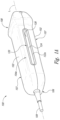
- FIG. 1A is an isometric side view of an ultrasound transducer probe 100 configured in accordance with one embodiment of the disclosed technology.
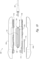
- FIGS. 1B and 1C are exploded isometric side views of the probe 100.
- FIG. 1D is an exploded side view of the probe 100.
- the probe 100 includes a housing 102 (e.g., an enclosure, a body, a shell, etc.) that defines a cavity 103.
- the housing 102 includes a first housing portion 102a (e.g., an upper portion) attached or otherwise bonded to a second housing portion 102b (e.g., a lower portion).
- the housing 102 further includes a first side portion 104a and a second side portion 104b on opposite sides of a longitudinal axis L extending through a proximal end portion 106, an intermediate portion 107 and a distal end portion 108 of the housing 102.
- a first aperture 122a e.g., an opening, a hole, etc.
- a second aperture 122b forms an elongated slot that extends longitudinally along the second side portion 104b.
- the first and second apertures 122a and 122b are configured to inhibit and/or block entry of a finger (e.g., an operator's finger, a patient's finger, etc.) therethrough.
- the first and second apertures 122a and 122b each have a length that extends between the proximal end portion 106 and the distal end portion 108 and a width that extends between the first housing portion 102a and the second housing portion 102b.
- one or both of the length or the width of either the first aperture 122a or the second aperture 122b has a dimension less than a diameter of typical finger (e.g., less than about 5mm).
- one or both of the first and second apertures 122a and 122b can include a length (e.g., between about 10mm and about 100mm, between about 15mm and about 35mm, or about 25mm) significantly greater than a width (e.g., between about 2mm and about 20mm, between about 3mm and about 5mm, or about 4mm).
- a grid and/or a mesh screen can be disposed within one or both of the first and second apertures 122a and 122b to inhibit entry of a finger.
- the housing 102 is configured to at least partially surround an ultrasound transducer assembly 110 (e.g., a single element ultrasound transducer, a one-dimensional ultrasound transducer array, a multi-dimensional ultrasound transducer array, etc.) positioned at least proximate the distal end portion 108.
- the transducer assembly 110 is electrically connected to system electronics 114 (identified separately as first system electronics 114a, second system electronics 114b and third system electronics 114c).
- the electronics 114 can include, for example, one or more digital signal processors, beamformers (e.g., analog and/or digital beamformers), image processors (e.g., one or more processors capable of processing B-mode images, M-mode images, Doppler images, etc.), electronic filters, etc.
- a cable 109 at the proximal end portion 106 communicatively couples the transducer assembly 110 and the system electronics 114 to an external computer and/or display (not/shown).
- a conduit 120 extends through the housing 102 from the first aperture 122a toward the second aperture 122b.
- the conduit 120 includes a first conduit opening 130a (e.g., an inlet/outlet) and a second conduit opening 130b positioned adjacent the first aperture 122a and the second aperture 122b, respectively.
- the conduit 120 further includes a proximal end portion 125a opposite a distal end portion 125b.
- the distal end portion 125b includes an exterior surface defining a pocket or recess configured to receive at least a portion of the transducer assembly 110.
- the conduit 120 is shown positioned in the intermediate portion 107 of the probe 100.
- the conduit 120 can be positioned at any suitable location within the housing 102.
- the probe 100 in FIGS. 1A-1D includes a single conduit 120. In other embodiments, however, the probe 100 can include a plurality of conduits 120 extending through the housing 102.
- An interior surface 128 of the conduit 120 defines a fluid path 124 (e.g., an air pathway, air passage, cavity, through hole, etc.) between the first aperture 122a and the second aperture 122b.
- the interior surface 128 of the illustrated embodiment is sealed such that air within the conduit 120 cannot flow into the cavity 103.
- the interior surface 128 can be at least partially open (e.g., via one or more holes or vents) to allow air in the fluid path 124 to flow in and out of the cavity 103.
- the interior surface 128 can be made from a material (e.g., copper, a copper alloy, aluminum, stainless steel, etc.) having a thermal conductivity greater than a material from which the housing 102 is formed.
- the interior surface 128 can be made of any suitable heat-resistant material (e.g., thermally conductive materials capable of withstanding temperatures greater than 100 degrees Celsius).
- the interior surface 128 can include one or more features (e.g., channels, grooves, ridges, notches, etc.) along at least a portion thereof to increase the surface area thereof, thereby increasing heat dissipation.
- a first heat spreader 118a and a second heat spreader 118b are positioned adjacent the conduit 120 and in thermal communication with the interior surface 128, the transducer assembly 110, the electronics 114.
- the first and second heat spreaders 118a and 118b can comprise, for example, copper, an alloy of copper and/or any other suitable thermally conductive material (e.g., aluminum, graphite, composites that include aluminum and/or copper, etc.).
- the first and second heat spreaders 118a and 118b are configured to absorb heat from the transducer assembly 110 and in the electronics 114 and transmit heat to the interior surface 128.
- the first and second heat spreaders 118a and 118b are directly bonded to the conduit 120 and/or at least partially integrated into the conduit 120. In other embodiments, however, the heat spreaders 118a and 118b are fully integrated with the conduit 120.
- the generation of ultrasound energy by the transducer assembly 110 during an ultrasound measurement procedure and/or the processing of ultrasound signals by the electronics 114 can produce significant amounts of heat.
- the transducer assembly 110 and electronics 114 may emit sufficient heat to raise a temperature at the interior surface 128 above for example, 60 degrees Celsius, which could be unsafe to touch.
- first and second apertures 122a and 122b are configured to inhibit entry of a finger, thus reducing and/or blocking access to the interior surface 128 to an operator's and/or patient's touch.
- the disclosed technology therefore is expected to increase an amount of heat that can be produced and/or dissipated by the probe 100 compared to other ultrasound probes without the housing 102 being uncomfortable or unsafe to touch or hold.
- a coolant C e.g., air, water and/or another suitable coolant
- the coolant C can enter the conduit 120 at a first temperature through either of the first conduit opening 130a or the second conduit opening 130b.
- the coolant C can absorb heat transmitted from, for example, the transducer assembly 110 and/or the electronics 114 via the heat spreaders 118a and 118b and the interior surface 128 thereby convectively cooling the probe 100 and one or more components contained therein.
- conduit 120 between the first and second apertures 122a and 122b is shown as a single continuous opening, it will be appreciated that multiple conduits connecting multiple holes or slots can be provided along the length of the probe 100. Accordingly, the invention is not limited except as by the appended claims.
Landscapes
- Health & Medical Sciences (AREA)
- Life Sciences & Earth Sciences (AREA)
- Biomedical Technology (AREA)
- Biophysics (AREA)
- Nuclear Medicine, Radiotherapy & Molecular Imaging (AREA)
- Pathology (AREA)
- Radiology & Medical Imaging (AREA)
- Engineering & Computer Science (AREA)
- Physics & Mathematics (AREA)
- Heart & Thoracic Surgery (AREA)
- Medical Informatics (AREA)
- Molecular Biology (AREA)
- Surgery (AREA)
- Animal Behavior & Ethology (AREA)
- General Health & Medical Sciences (AREA)
- Public Health (AREA)
- Veterinary Medicine (AREA)
- Ultra Sonic Daignosis Equipment (AREA)
- Gynecology & Obstetrics (AREA)
Description
- The disclosed technology relates generally to ultrasound probes, and more specifically to systems and methods of reducing heat of ultrasound probes.
-
US 5,560,362 discloses an ultrasound transducer assembly having a housing, a transducer array mounted in the housing, and active cooling mechanism positioned adjacent to the transducer array for actively removing heat generated by the array by transport of heat energy from the affected site.US 2010/0109480 A1 discloses a method for manufacturing a membrane and an ultrasonic transducer provide with such a front membrane.JP 2008284003 US 5,494,038 discloses an apparatus for ultrasound testing.US 2013/0286593 A1 andUS 2013/0338508 A1 both disclose ultrasonic probes. - The present invention provides an ultrasound transducer probe according to claim 1. Optional features are recited in the dependent claim.
-
-
FIG. 1A is an isometric side view of an ultrasound transducer configured in accordance with the disclosed technology. -
FIGS. .1B and1C are isometric side exploded views of the ultrasound transducer ofFIG. 1A . -
FIG. 1D is a side exploded view of the ultrasound transducer ofFIG. 1A . - The disclosed technology is generally directed to systems and methods of cooling ultrasound transducers. It will be appreciated that several of the details set forth below are provided to describe the following embodiments in a manner sufficient to enable a person skilled in the relevant art to make and use the disclosed embodiments. Several of the details described below, however, may not be necessary to practice certain embodiments of the technology. Additionally, the technology can include other embodiments that are within the scope of the claims but are not described in detail with reference to
FIGS. 1A-D . - The disclosed technology can reduce an amount of heat emitted from an outer surface of an ultrasound probe. During an ultrasound procedure, for example, an ultrasound transducer in the probe generates, transmits and receives ultrasound energy. Electronics in the probe (e.g., beamforming electronics) can process the signals and produce ultrasound data that can be used to form an ultrasound image. The generation of the ultrasound energy and processing of the ultrasound data can, in some instances, produce temperatures in excess of 60 degrees Celsius within the probe. Such temperatures may raise a temperature of at least a portion of the outer surface of the probe to a point of being uncomfortable or unsafe for an operator to hold and/or a patient to touch. Embodiments of the present technology include, for example, one or more conduits extending through an ultrasound probe allowing internal components to emit heat to air flowing through the conduit(s), thereby reducing a temperature along the outer surface of the probe and/or at the ultrasound transducer array.
-
FIG. 1A is an isometric side view of anultrasound transducer probe 100 configured in accordance with one embodiment of the disclosed technology.FIGS. 1B and1C are exploded isometric side views of theprobe 100.FIG. 1D is an exploded side view of theprobe 100. Referring first toFIGS. 1A-1D together, theprobe 100 includes a housing 102 (e.g., an enclosure, a body, a shell, etc.) that defines a cavity 103. Thehousing 102 includes afirst housing portion 102a (e.g., an upper portion) attached or otherwise bonded to asecond housing portion 102b (e.g., a lower portion). Thehousing 102 further includes a first side portion 104a and asecond side portion 104b on opposite sides of a longitudinal axis L extending through aproximal end portion 106, anintermediate portion 107 and adistal end portion 108 of thehousing 102. Afirst aperture 122a (e.g., an opening, a hole, etc.) forms an elongated slot that extends longitudinally along the first side portion 104a. Asecond aperture 122b (e.g., an opening, a hole, etc.) forms an elongated slot that extends longitudinally along thesecond side portion 104b. The first andsecond apertures second apertures proximal end portion 106 and thedistal end portion 108 and a width that extends between thefirst housing portion 102a and thesecond housing portion 102b. In one embodiment, one or both of the length or the width of either thefirst aperture 122a or thesecond aperture 122b has a dimension less than a diameter of typical finger (e.g., less than about 5mm). In some embodiments, for example, one or both of the first andsecond apertures second apertures - The
housing 102 is configured to at least partially surround an ultrasound transducer assembly 110 (e.g., a single element ultrasound transducer, a one-dimensional ultrasound transducer array, a multi-dimensional ultrasound transducer array, etc.) positioned at least proximate thedistal end portion 108. Thetransducer assembly 110 is electrically connected to system electronics 114 (identified separately asfirst system electronics 114a,second system electronics 114b andthird system electronics 114c). The electronics 114 can include, for example, one or more digital signal processors, beamformers (e.g., analog and/or digital beamformers), image processors (e.g., one or more processors capable of processing B-mode images, M-mode images, Doppler images, etc.), electronic filters, etc. Acable 109 at theproximal end portion 106 communicatively couples thetransducer assembly 110 and the system electronics 114 to an external computer and/or display (not/shown). - A conduit 120 (e.g., a duct, tube, etc.) extends through the
housing 102 from thefirst aperture 122a toward thesecond aperture 122b. Theconduit 120 includes a first conduit opening 130a (e.g., an inlet/outlet) and a second conduit opening 130b positioned adjacent thefirst aperture 122a and thesecond aperture 122b, respectively. Theconduit 120 further includes aproximal end portion 125a opposite adistal end portion 125b. Thedistal end portion 125b includes an exterior surface defining a pocket or recess configured to receive at least a portion of thetransducer assembly 110. In the illustrated embodiment, theconduit 120 is shown positioned in theintermediate portion 107 of theprobe 100. In other embodiments, however, theconduit 120 can be positioned at any suitable location within thehousing 102. Moreover, theprobe 100 inFIGS. 1A-1D includes asingle conduit 120. In other embodiments, however, theprobe 100 can include a plurality ofconduits 120 extending through thehousing 102. - An
interior surface 128 of theconduit 120 defines a fluid path 124 (e.g., an air pathway, air passage, cavity, through hole, etc.) between thefirst aperture 122a and thesecond aperture 122b. Theinterior surface 128 of the illustrated embodiment is sealed such that air within theconduit 120 cannot flow into the cavity 103. In some embodiments, however, theinterior surface 128 can be at least partially open (e.g., via one or more holes or vents) to allow air in thefluid path 124 to flow in and out of the cavity 103. Theinterior surface 128 can be made from a material (e.g., copper, a copper alloy, aluminum, stainless steel, etc.) having a thermal conductivity greater than a material from which thehousing 102 is formed. In other embodiments, however, theinterior surface 128 can be made of any suitable heat-resistant material (e.g., thermally conductive materials capable of withstanding temperatures greater than 100 degrees Celsius). In further embodiments, theinterior surface 128 can include one or more features (e.g., channels, grooves, ridges, notches, etc.) along at least a portion thereof to increase the surface area thereof, thereby increasing heat dissipation. - A first heat spreader 118a and a
second heat spreader 118b are positioned adjacent theconduit 120 and in thermal communication with theinterior surface 128, thetransducer assembly 110, the electronics 114. The first andsecond heat spreaders 118a and 118b can comprise, for example, copper, an alloy of copper and/or any other suitable thermally conductive material (e.g., aluminum, graphite, composites that include aluminum and/or copper, etc.). The first andsecond heat spreaders 118a and 118b are configured to absorb heat from thetransducer assembly 110 and in the electronics 114 and transmit heat to theinterior surface 128. In some embodiments, for example, the first andsecond heat spreaders 118a and 118b are directly bonded to theconduit 120 and/or at least partially integrated into theconduit 120. In other embodiments, however, theheat spreaders 118a and 118b are fully integrated with theconduit 120. - The generation of ultrasound energy by the
transducer assembly 110 during an ultrasound measurement procedure and/or the processing of ultrasound signals by the electronics 114can produce significant amounts of heat. For example, during an ultrasound procedure, thetransducer assembly 110 and electronics 114 may emit sufficient heat to raise a temperature at theinterior surface 128 above for example, 60 degrees Celsius, which could be unsafe to touch. As explained above, however, first andsecond apertures interior surface 128 to an operator's and/or patient's touch. The disclosed technology therefore is expected to increase an amount of heat that can be produced and/or dissipated by theprobe 100 compared to other ultrasound probes without thehousing 102 being uncomfortable or unsafe to touch or hold. - In operation, a coolant C (e.g., air, water and/or another suitable coolant) can enter the
conduit 120, flow through thefluid path 124 and absorb heat generated by components in theprobe 100 before exiting theconduit 120. The coolant C, for example, can enter theconduit 120 at a first temperature through either of the first conduit opening 130a or the second conduit opening 130b. As the coolant C flows through thefluid path 124 in theconduit 120, the coolant C can absorb heat transmitted from, for example, thetransducer assembly 110 and/or the electronics 114 via theheat spreaders 118a and 118b and theinterior surface 128 thereby convectively cooling theprobe 100 and one or more components contained therein. - From the foregoing, it will be appreciated that specific embodiments of the invention have been described herein for purposes of illustration, but that various modifications may be made without deviating from the scope of the claims.
- For example, although the
conduit 120 between the first andsecond apertures probe 100. Accordingly, the invention is not limited except as by the appended claims.
Claims (15)
- An imaging ultrasound transducer probe (100), comprising:a transducer assembly (110) provided at a distal end of the probe (100);electronics (114) configured to drive the transducer assembly (110);a housing (102) at least partially enclosing the transducer assembly (110) and the electronics (114) having a longitudinal axis (L) extending between a proximal end of the probe (100) and the distal end of the probe (100);a heat spreader (118a) configured to absorb heat from the transducer assembly (110) and the electronics (114); and characterised by:
a conduit (120) extending from a first side (104a) of the housing (102) to a second side (104b) of the housing (102), wherein the first side (104a) and the second side (104b) are located on opposite sides of the longitudinal axis (L) of the housing (102), wherein the heat spreader (118a) is located between the electronics (114) and an exterior surface of the conduit (120), and wherein the conduit (120) is configured to allow air to flow through the conduit (120) from the first side (104a) of the housing (102) to the second side (104b) of the housing (102) to dissipate the heat absorbed by the heat spreader (118a). - The ultrasound transducer probe (100) of claim 1, wherein the conduit (120) has an interior surface (128) sealed from an interior portion of the housing (102).
- The ultrasound transducer probe (100) of claim 1, wherein the conduit (120) extends from a first aperture (122a) that forms an elongated slot in the first side (104a) of the housing (102) to a second aperture (122b) that forms an elongated slot in the second side (104b) of the housing (102).
- The ultrasound transducer probe (100) of claim 3, wherein each of the first aperture (122a) and the second aperture (122b) has a length and a width, wherein the width is less than the length.
- The ultrasound transducer probe (100) of claim 1, wherein the heat spreader (118a) is bonded to the conduit (120).
- The ultrasound transducer probe (100) of claim 1, wherein the heat spreader (118a) is integral to the conduit (120).
- The ultrasound transducer probe (100) of claim 1, wherein a first aperture (122a) in the first side is in fluid communication with a second aperture (122b) in the second side via the conduit (120), and wherein the conduit (120) includes a sealed interior surface (128) that defines a cavity (103).
- The ultrasound transducer probe (100) of claim 7, wherein the first aperture (122a) and the second aperture (122b) are configured to prevent accessibility to the cavity (103) and the interior surface (128) of the conduit (120) by a finger of an operator.
- The ultrasound transducer probe (100) of claim 1, wherein an exterior surface at the distal end of the conduit (120) includes a recess that is configured to receive at least a portion of the transducer assembly (110).
- The ultrasound transducer probe (100) of claim 1, wherein an interior surface (128) of the conduit (120) has a thermal conductivity that is greater than the thermal conductivity of the housing (102).
- The ultrasound transducer probe (100) of claim 1, wherein the housing (102) is configured to dissipate heat at a temperature less than or equal to a first temperature, and wherein an interior surface (128) of the conduit (120) is configured to dissipate heat at a second temperature greater than the first temperature.
- The ultrasound transducer probe (100) of claim 1, wherein the conduit (120) includes a plurality of grooves.
- The ultrasound transducer probe (100) of claim 1, wherein the conduit (120) is a first conduit, and wherein a first aperture (122a) in the first side (104a) is in fluid communication with a second aperture (122b) in the second side (104b) via the first conduit (120) that includes a sealed interior surface (128) that defines a first cavity (103), and wherein the ultrasound probe (100) further comprises:a second conduit extending through the housing (102), wherein the second conduit includes an interior surface that defines a second cavity; anda third aperture in fluid communication with a fourth conduit via the second cavity wherein the third aperture and fourth aperture extend along different outer surfaces of the housing (102).
- The ultrasound transducer probe (100) of claim 1, wherein the heat spreader (118a) has a thermal conductivity that is higher than the thermal conductivity of the housing (102).
- The ultrasound transducer probe (100) of claim 1, wherein the heat spreader (118a) is a first heat spreader at an upper portion of the conduit (120), and the probe comprises a second heat spreader (118b) at a lower portion of the conduit (120), wherein each of the first heat spreader (118a) and the second heat spreader (118b) is configured to transmit the heat from the transducer assembly (110) and the electronics (114) to the conduit (120).
Applications Claiming Priority (3)
| Application Number | Priority Date | Filing Date | Title |
|---|---|---|---|
| US14/301,299 US11540813B2 (en) | 2014-06-10 | 2014-06-10 | Handheld ultrasound imaging systems and methods for cooling transducers and electronics in the probe housing via air circulation through the housing |
| EP15806744.7A EP3154437B1 (en) | 2014-06-10 | 2015-06-09 | Systems for cooling ultrasound transducers |
| PCT/US2015/034980 WO2015191643A1 (en) | 2014-06-10 | 2015-06-09 | Systems and methods for cooling ultrasound transducers |
Related Parent Applications (2)
| Application Number | Title | Priority Date | Filing Date |
|---|---|---|---|
| EP15806744.7A Division EP3154437B1 (en) | 2014-06-10 | 2015-06-09 | Systems for cooling ultrasound transducers |
| EP15806744.7A Division-Into EP3154437B1 (en) | 2014-06-10 | 2015-06-09 | Systems for cooling ultrasound transducers |
Publications (2)
| Publication Number | Publication Date |
|---|---|
| EP3847971A1 EP3847971A1 (en) | 2021-07-14 |
| EP3847971B1 true EP3847971B1 (en) | 2024-09-04 |
Family
ID=54768620
Family Applications (2)
| Application Number | Title | Priority Date | Filing Date |
|---|---|---|---|
| EP21159724.0A Active EP3847971B1 (en) | 2014-06-10 | 2015-06-09 | Systems for cooling ultrasound transducers |
| EP15806744.7A Active EP3154437B1 (en) | 2014-06-10 | 2015-06-09 | Systems for cooling ultrasound transducers |
Family Applications After (1)
| Application Number | Title | Priority Date | Filing Date |
|---|---|---|---|
| EP15806744.7A Active EP3154437B1 (en) | 2014-06-10 | 2015-06-09 | Systems for cooling ultrasound transducers |
Country Status (5)
| Country | Link |
|---|---|
| US (2) | US11540813B2 (en) |
| EP (2) | EP3847971B1 (en) |
| JP (1) | JP6615125B2 (en) |
| CN (2) | CN106659469B (en) |
| WO (1) | WO2015191643A1 (en) |
Families Citing this family (17)
| Publication number | Priority date | Publication date | Assignee | Title |
|---|---|---|---|---|
| USD770629S1 (en) * | 2015-04-30 | 2016-11-01 | Fujifilm Sonosite, Inc. | Ultrasound probe |
| USD770630S1 (en) * | 2015-04-30 | 2016-11-01 | Fujifilm Sonosite, Inc. | Ultrasound probe |
| US10779801B2 (en) * | 2016-09-21 | 2020-09-22 | Clarius Mobile Health Corp. | Ultrasound apparatus with improved heat dissipation and methods for providing same |
| CN106214181A (en) * | 2016-10-12 | 2016-12-14 | 湖南润泽医疗影像科技有限公司 | A kind of low-consumption wireless palm color ultrasound system |
| CN106264608A (en) * | 2016-10-12 | 2017-01-04 | 湖南润泽医疗影像科技有限公司 | Wireless color ultrasound 3D imaging system and data processing method |
| CN106473773A (en) * | 2016-10-12 | 2017-03-08 | 湖南润泽医疗影像科技有限公司 | A kind of integrated wireless palm color ultrasound |
| JP6548234B2 (en) | 2017-11-30 | 2019-07-24 | ゼネラル・エレクトリック・カンパニイ | Ultrasonic probe and ultrasonic image display apparatus |
| US10908270B2 (en) * | 2018-01-18 | 2021-02-02 | Fujifilm Sonosite, Inc. | Portable ultrasound imaging system with active cooling |
| KR102607018B1 (en) * | 2018-01-31 | 2023-11-29 | 삼성메디슨 주식회사 | Ultrasonic probe |
| CN108742701B (en) * | 2018-03-27 | 2021-11-12 | 苏州佳世达电通有限公司 | Expansion module and expansion module for ultrasonic system |
| CN109121364A (en) * | 2018-09-03 | 2019-01-01 | 飞依诺科技(苏州)有限公司 | Air-cooled soakage device and hand-held ultrasound detection device |
| US12396709B2 (en) * | 2018-12-07 | 2025-08-26 | General Electric Company | Ultrasound probe and method of making the same |
| US12304152B2 (en) * | 2019-05-13 | 2025-05-20 | Koninklijke Philips N.V. | Ultrasound probe handle |
| USD1002015S1 (en) * | 2021-07-01 | 2023-10-17 | Healcerion Co., Ltd. | Ultrasonic probe |
| US12564388B2 (en) * | 2022-01-25 | 2026-03-03 | GE Precision Healthcare, LLC | Phase change insert for ultrasound imaging probe |
| KR200497687Y1 (en) * | 2023-10-13 | 2024-01-25 | 주식회사 한소노 | Ultrasound device |
| CN118376687B (en) * | 2024-06-24 | 2024-10-29 | 苏州南智芯材科技有限公司 | Crystal crack detection device, crystal growth furnace and crystal crack detection method |
Family Cites Families (45)
| Publication number | Priority date | Publication date | Assignee | Title |
|---|---|---|---|---|
| US4973247A (en) * | 1989-09-20 | 1990-11-27 | Varnes Dewayne L | Dental handpiece assembly |
| JPH04250145A (en) * | 1991-01-25 | 1992-09-07 | Toshiba Corp | Ultrasonic probe |
| US5551945A (en) * | 1993-03-16 | 1996-09-03 | Olympus Optical Co., Ltd. | Endoscope system including endoscope and protection cover |
| US5353868A (en) * | 1993-04-19 | 1994-10-11 | Abbott Roy W | Integral tube and strip fin heat exchanger circuit |
| US5560362A (en) * | 1994-06-13 | 1996-10-01 | Acuson Corporation | Active thermal control of ultrasound transducers |
| JPH08249532A (en) * | 1995-03-09 | 1996-09-27 | Shibaura Eng Works Co Ltd | vending machine |
| US5494038A (en) | 1995-04-25 | 1996-02-27 | Abbott Laboratories | Apparatus for ultrasound testing |
| US6142945A (en) * | 1997-11-26 | 2000-11-07 | Fuji Photo Optical Co., Ltd. | Balloon anchor for endoscopically inserting ultrasound probe |
| US5961465A (en) * | 1998-02-10 | 1999-10-05 | Hewlett-Packard Company | Ultrasound signal processing electronics with active cooling |
| US7686763B2 (en) * | 1998-09-18 | 2010-03-30 | University Of Washington | Use of contrast agents to increase the effectiveness of high intensity focused ultrasound therapy |
| US6142947A (en) | 1998-12-04 | 2000-11-07 | General Electric Company | Ultrasound probe and related methods of assembly/disassembly |
| JP2000315880A (en) * | 1999-05-06 | 2000-11-14 | Toshiba Corp | Circuit housing |
| US20030204199A1 (en) | 2002-04-30 | 2003-10-30 | Novak Theodore A. D. | Device and method for ultrasonic tissue excision with tissue selectivity |
| US20050180894A1 (en) * | 2004-02-13 | 2005-08-18 | Affymetrix, Inc. | System, method, and product for efficient fluid transfer using and addressable adaptor |
| JP2006020755A (en) * | 2004-07-07 | 2006-01-26 | Toshiba Corp | Portable medical device |
| JP4685408B2 (en) | 2004-10-27 | 2011-05-18 | 株式会社東芝 | Ultrasonic probe |
| DE602005011644D1 (en) * | 2004-10-27 | 2009-01-22 | Toshiba Kk | Ultrasonic probe and ultrasonic diagnostic device |
| US20060173344A1 (en) * | 2005-01-19 | 2006-08-03 | Siemens Medical Solutions Usa, Inc. | Method for using a refrigeration system to remove waste heat from an ultrasound transducer |
| US10357662B2 (en) * | 2009-02-19 | 2019-07-23 | Pthera LLC | Apparatus and method for irradiating a surface with light |
| JP4851210B2 (en) * | 2006-03-15 | 2012-01-11 | 日立アロカメディカル株式会社 | Ultrasonic diagnostic equipment |
| US8475375B2 (en) * | 2006-12-15 | 2013-07-02 | General Electric Company | System and method for actively cooling an ultrasound probe |
| DE602006014291D1 (en) | 2006-12-29 | 2010-06-24 | Ultrazonix Dnt Ab | Manufacturing process for a membrane and article provided with such a membrane |
| JP4870591B2 (en) | 2007-02-14 | 2012-02-08 | 日立アロカメディカル株式会社 | Probe connector for ultrasonic diagnostic equipment |
| JP2008284003A (en) | 2007-05-15 | 2008-11-27 | Aloka Co Ltd | Ultrasonic probe |
| JP2008307086A (en) * | 2007-06-12 | 2008-12-25 | Toshiba Corp | Ultrasonic diagnostic equipment |
| US8746330B2 (en) | 2007-08-09 | 2014-06-10 | Coolit Systems Inc. | Fluid heat exchanger configured to provide a split flow |
| CN101911178A (en) | 2007-12-27 | 2010-12-08 | 皇家飞利浦电子股份有限公司 | Ultrasonic transducer assembly with improved thermal behavior |
| JP5258493B2 (en) | 2008-10-07 | 2013-08-07 | 株式会社東芝 | Ultrasonic probe |
| US20100228130A1 (en) | 2009-03-09 | 2010-09-09 | Teratech Corporation | Portable ultrasound imaging system |
| JP5619380B2 (en) * | 2009-06-24 | 2014-11-05 | 株式会社東芝 | Ultrasonic probe |
| WO2011055315A1 (en) | 2009-11-09 | 2011-05-12 | Koninklijke Philips Electronics N.V. | Curved ultrasonic hifu transducer with air cooling passageway |
| CN203398243U (en) | 2010-05-21 | 2014-01-15 | 格拉弗技术国际控股有限公司 | Thermal management component with opposite main surfaces for battery unit |
| US8932279B2 (en) * | 2011-04-08 | 2015-01-13 | Domain Surgical, Inc. | System and method for cooling of a heated surgical instrument and/or surgical site and treating tissue |
| US9730677B2 (en) * | 2011-05-17 | 2017-08-15 | Koninklijke Philips Electronics N.V. | Matrix ultrasound probe with passive heat dissipation |
| US20130172751A1 (en) * | 2012-01-02 | 2013-07-04 | General Electric Company | Systems and methods for shock absorbing in ultrasound probes |
| CN104205206B (en) * | 2012-03-20 | 2017-10-20 | 皇家飞利浦有限公司 | Ultrasonic matrix array probe with radiating cable and pad heat exchanger |
| WO2013140311A2 (en) * | 2012-03-20 | 2013-09-26 | Koninklijke Philips N.V. | Ultrasonic matrix array probe with thermally dissipating cable and heat exchanger |
| KR101330733B1 (en) | 2012-04-30 | 2013-11-20 | 삼성전자주식회사 | Ultrasonic Probe |
| JP6065421B2 (en) * | 2012-06-15 | 2017-01-25 | セイコーエプソン株式会社 | Ultrasonic probe and ultrasonic inspection device |
| PL2908758T3 (en) | 2012-10-22 | 2016-12-30 | Electromagnetic skin treatment device | |
| KR101534913B1 (en) * | 2013-06-17 | 2015-07-08 | 현대자동차주식회사 | Battery pack air cooling structure provided with thermoelectric element and method thereof |
| KR101532137B1 (en) * | 2013-07-23 | 2015-06-26 | 삼성전기주식회사 | Dielectric composition for low temperature sintering, multilayer ceramic electronic device including the same and method for fabricating the multilayer ceramic electronic device |
| JP2016202190A (en) * | 2013-09-02 | 2016-12-08 | 株式会社日立製作所 | Ultrasonic diagnostic equipment |
| CN103519849B (en) * | 2013-10-21 | 2015-06-03 | 深圳开立生物医疗科技股份有限公司 | Cooling mechanism and ultrasonic probe |
| WO2015129938A1 (en) * | 2014-02-27 | 2015-09-03 | 알피니언메디칼시스템 주식회사 | Ultrasonic probe having improved heat dissipation characteristics |
-
2014
- 2014-06-10 US US14/301,299 patent/US11540813B2/en active Active
-
2015
- 2015-06-09 JP JP2016572240A patent/JP6615125B2/en active Active
- 2015-06-09 EP EP21159724.0A patent/EP3847971B1/en active Active
- 2015-06-09 CN CN201580042846.4A patent/CN106659469B/en active Active
- 2015-06-09 WO PCT/US2015/034980 patent/WO2015191643A1/en not_active Ceased
- 2015-06-09 CN CN202110388815.1A patent/CN113288203A/en active Pending
- 2015-06-09 EP EP15806744.7A patent/EP3154437B1/en active Active
-
2022
- 2022-12-08 US US18/063,084 patent/US12521097B2/en active Active
Also Published As
| Publication number | Publication date |
|---|---|
| US20150351727A1 (en) | 2015-12-10 |
| US11540813B2 (en) | 2023-01-03 |
| CN106659469A (en) | 2017-05-10 |
| JP2017517330A (en) | 2017-06-29 |
| EP3154437B1 (en) | 2021-08-11 |
| EP3847971A1 (en) | 2021-07-14 |
| EP3154437A4 (en) | 2018-03-28 |
| JP6615125B2 (en) | 2019-12-04 |
| CN113288203A (en) | 2021-08-24 |
| US20230107276A1 (en) | 2023-04-06 |
| WO2015191643A1 (en) | 2015-12-17 |
| EP3154437A1 (en) | 2017-04-19 |
| CN106659469B (en) | 2021-04-30 |
| US12521097B2 (en) | 2026-01-13 |
Similar Documents
| Publication | Publication Date | Title |
|---|---|---|
| US12521097B2 (en) | Systems and methods for air cooled ultrasound transducers via cavity on the probe | |
| JP6149100B2 (en) | Ultrasonic transducer probe assembly | |
| RU2604705C2 (en) | Matrix ultrasound probe with passive heat dissipation | |
| CN102068278B (en) | Ultrasonic probe and ultrasonic diagnostic apparatus | |
| CN100441149C (en) | Ultrasound probes and ultrasonic diagnostic devices | |
| JP2015510806A (en) | Ultrasonic transducer probe assembly | |
| US8544330B2 (en) | Method and system for cooling an ultrasound probe | |
| US20080188755A1 (en) | Ultrasound Transducer Assembly Having Improved Thermal Management | |
| EP4041463B1 (en) | Systems and methods for cooling ultrasound transducers and ultrasound transducer arrays | |
| US12268559B2 (en) | Systems and methods of dissipating heat from a handheld medical imaging device | |
| EP2845541A1 (en) | Probe for ultrasonic diagnostic apparatus | |
| EP4312788B1 (en) | Heat dissipation in ultrasound probes | |
| KR20100122060A (en) | Ultrasonic probe | |
| EP2878269B1 (en) | Ultrasonic probe | |
| US20180014813A1 (en) | Ultrasound transducer probe with heat transfer device | |
| CN102397085B (en) | Ultrasound probe | |
| KR100992446B1 (en) | Probe | |
| WO2018120770A1 (en) | Ultrasonic probe and housing thereof | |
| US12558072B2 (en) | Ultrasound probe with improved thermal management | |
| KR20160101144A (en) | Heat radiation structure of ultrasonic transducer | |
| JP2023519208A (en) | Heat dissipation arrangements for medical devices and related devices, systems, and methods |
Legal Events
| Date | Code | Title | Description |
|---|---|---|---|
| PUAI | Public reference made under article 153(3) epc to a published international application that has entered the european phase |
Free format text: ORIGINAL CODE: 0009012 |
|
| STAA | Information on the status of an ep patent application or granted ep patent |
Free format text: STATUS: THE APPLICATION HAS BEEN PUBLISHED |
|
| AC | Divisional application: reference to earlier application |
Ref document number: 3154437 Country of ref document: EP Kind code of ref document: P |
|
| AK | Designated contracting states |
Kind code of ref document: A1 Designated state(s): AL AT BE BG CH CY CZ DE DK EE ES FI FR GB GR HR HU IE IS IT LI LT LU LV MC MK MT NL NO PL PT RO RS SE SI SK SM TR |
|
| STAA | Information on the status of an ep patent application or granted ep patent |
Free format text: STATUS: REQUEST FOR EXAMINATION WAS MADE |
|
| 17P | Request for examination filed |
Effective date: 20220106 |
|
| RBV | Designated contracting states (corrected) |
Designated state(s): AL AT BE BG CH CY CZ DE DK EE ES FI FR GB GR HR HU IE IS IT LI LT LU LV MC MK MT NL NO PL PT RO RS SE SI SK SM TR |
|
| GRAP | Despatch of communication of intention to grant a patent |
Free format text: ORIGINAL CODE: EPIDOSNIGR1 |
|
| STAA | Information on the status of an ep patent application or granted ep patent |
Free format text: STATUS: GRANT OF PATENT IS INTENDED |
|
| INTG | Intention to grant announced |
Effective date: 20240328 |
|
| GRAS | Grant fee paid |
Free format text: ORIGINAL CODE: EPIDOSNIGR3 |
|
| GRAA | (expected) grant |
Free format text: ORIGINAL CODE: 0009210 |
|
| STAA | Information on the status of an ep patent application or granted ep patent |
Free format text: STATUS: THE PATENT HAS BEEN GRANTED |
|
| AC | Divisional application: reference to earlier application |
Ref document number: 3154437 Country of ref document: EP Kind code of ref document: P |
|
| AK | Designated contracting states |
Kind code of ref document: B1 Designated state(s): AL AT BE BG CH CY CZ DE DK EE ES FI FR GB GR HR HU IE IS IT LI LT LU LV MC MK MT NL NO PL PT RO RS SE SI SK SM TR |
|
| REG | Reference to a national code |
Ref country code: GB Ref legal event code: FG4D |
|
| REG | Reference to a national code |
Ref country code: CH Ref legal event code: EP |
|
| REG | Reference to a national code |
Ref country code: IE Ref legal event code: FG4D Ref country code: NL Ref legal event code: FP |
|
| REG | Reference to a national code |
Ref country code: DE Ref legal event code: R096 Ref document number: 602015089835 Country of ref document: DE |
|
| REG | Reference to a national code |
Ref country code: LT Ref legal event code: MG9D |
|
| PG25 | Lapsed in a contracting state [announced via postgrant information from national office to epo] |
Ref country code: NO Free format text: LAPSE BECAUSE OF FAILURE TO SUBMIT A TRANSLATION OF THE DESCRIPTION OR TO PAY THE FEE WITHIN THE PRESCRIBED TIME-LIMIT Effective date: 20241204 |
|
| PG25 | Lapsed in a contracting state [announced via postgrant information from national office to epo] |
Ref country code: GR Free format text: LAPSE BECAUSE OF FAILURE TO SUBMIT A TRANSLATION OF THE DESCRIPTION OR TO PAY THE FEE WITHIN THE PRESCRIBED TIME-LIMIT Effective date: 20241205 Ref country code: FI Free format text: LAPSE BECAUSE OF FAILURE TO SUBMIT A TRANSLATION OF THE DESCRIPTION OR TO PAY THE FEE WITHIN THE PRESCRIBED TIME-LIMIT Effective date: 20240904 Ref country code: PL Free format text: LAPSE BECAUSE OF FAILURE TO SUBMIT A TRANSLATION OF THE DESCRIPTION OR TO PAY THE FEE WITHIN THE PRESCRIBED TIME-LIMIT Effective date: 20240904 |
|
| PG25 | Lapsed in a contracting state [announced via postgrant information from national office to epo] |
Ref country code: BG Free format text: LAPSE BECAUSE OF FAILURE TO SUBMIT A TRANSLATION OF THE DESCRIPTION OR TO PAY THE FEE WITHIN THE PRESCRIBED TIME-LIMIT Effective date: 20240904 |
|
| PG25 | Lapsed in a contracting state [announced via postgrant information from national office to epo] |
Ref country code: LV Free format text: LAPSE BECAUSE OF FAILURE TO SUBMIT A TRANSLATION OF THE DESCRIPTION OR TO PAY THE FEE WITHIN THE PRESCRIBED TIME-LIMIT Effective date: 20240904 |
|
| PG25 | Lapsed in a contracting state [announced via postgrant information from national office to epo] |
Ref country code: HR Free format text: LAPSE BECAUSE OF FAILURE TO SUBMIT A TRANSLATION OF THE DESCRIPTION OR TO PAY THE FEE WITHIN THE PRESCRIBED TIME-LIMIT Effective date: 20240904 |
|
| PG25 | Lapsed in a contracting state [announced via postgrant information from national office to epo] |
Ref country code: ES Free format text: LAPSE BECAUSE OF FAILURE TO SUBMIT A TRANSLATION OF THE DESCRIPTION OR TO PAY THE FEE WITHIN THE PRESCRIBED TIME-LIMIT Effective date: 20240904 Ref country code: RS Free format text: LAPSE BECAUSE OF FAILURE TO SUBMIT A TRANSLATION OF THE DESCRIPTION OR TO PAY THE FEE WITHIN THE PRESCRIBED TIME-LIMIT Effective date: 20241204 |
|
| PG25 | Lapsed in a contracting state [announced via postgrant information from national office to epo] |
Ref country code: RS Free format text: LAPSE BECAUSE OF FAILURE TO SUBMIT A TRANSLATION OF THE DESCRIPTION OR TO PAY THE FEE WITHIN THE PRESCRIBED TIME-LIMIT Effective date: 20241204 Ref country code: PL Free format text: LAPSE BECAUSE OF FAILURE TO SUBMIT A TRANSLATION OF THE DESCRIPTION OR TO PAY THE FEE WITHIN THE PRESCRIBED TIME-LIMIT Effective date: 20240904 Ref country code: NO Free format text: LAPSE BECAUSE OF FAILURE TO SUBMIT A TRANSLATION OF THE DESCRIPTION OR TO PAY THE FEE WITHIN THE PRESCRIBED TIME-LIMIT Effective date: 20241204 Ref country code: LV Free format text: LAPSE BECAUSE OF FAILURE TO SUBMIT A TRANSLATION OF THE DESCRIPTION OR TO PAY THE FEE WITHIN THE PRESCRIBED TIME-LIMIT Effective date: 20240904 Ref country code: HR Free format text: LAPSE BECAUSE OF FAILURE TO SUBMIT A TRANSLATION OF THE DESCRIPTION OR TO PAY THE FEE WITHIN THE PRESCRIBED TIME-LIMIT Effective date: 20240904 Ref country code: GR Free format text: LAPSE BECAUSE OF FAILURE TO SUBMIT A TRANSLATION OF THE DESCRIPTION OR TO PAY THE FEE WITHIN THE PRESCRIBED TIME-LIMIT Effective date: 20241205 Ref country code: FI Free format text: LAPSE BECAUSE OF FAILURE TO SUBMIT A TRANSLATION OF THE DESCRIPTION OR TO PAY THE FEE WITHIN THE PRESCRIBED TIME-LIMIT Effective date: 20240904 Ref country code: ES Free format text: LAPSE BECAUSE OF FAILURE TO SUBMIT A TRANSLATION OF THE DESCRIPTION OR TO PAY THE FEE WITHIN THE PRESCRIBED TIME-LIMIT Effective date: 20240904 Ref country code: BG Free format text: LAPSE BECAUSE OF FAILURE TO SUBMIT A TRANSLATION OF THE DESCRIPTION OR TO PAY THE FEE WITHIN THE PRESCRIBED TIME-LIMIT Effective date: 20240904 |
|
| REG | Reference to a national code |
Ref country code: AT Ref legal event code: MK05 Ref document number: 1719525 Country of ref document: AT Kind code of ref document: T Effective date: 20240904 |
|
| PG25 | Lapsed in a contracting state [announced via postgrant information from national office to epo] |
Ref country code: PT Free format text: LAPSE BECAUSE OF FAILURE TO SUBMIT A TRANSLATION OF THE DESCRIPTION OR TO PAY THE FEE WITHIN THE PRESCRIBED TIME-LIMIT Effective date: 20250106 Ref country code: IS Free format text: LAPSE BECAUSE OF FAILURE TO SUBMIT A TRANSLATION OF THE DESCRIPTION OR TO PAY THE FEE WITHIN THE PRESCRIBED TIME-LIMIT Effective date: 20250104 |
|
| PG25 | Lapsed in a contracting state [announced via postgrant information from national office to epo] |
Ref country code: RO Free format text: LAPSE BECAUSE OF FAILURE TO SUBMIT A TRANSLATION OF THE DESCRIPTION OR TO PAY THE FEE WITHIN THE PRESCRIBED TIME-LIMIT Effective date: 20240904 Ref country code: SM Free format text: LAPSE BECAUSE OF FAILURE TO SUBMIT A TRANSLATION OF THE DESCRIPTION OR TO PAY THE FEE WITHIN THE PRESCRIBED TIME-LIMIT Effective date: 20240904 |
|
| PG25 | Lapsed in a contracting state [announced via postgrant information from national office to epo] |
Ref country code: EE Free format text: LAPSE BECAUSE OF FAILURE TO SUBMIT A TRANSLATION OF THE DESCRIPTION OR TO PAY THE FEE WITHIN THE PRESCRIBED TIME-LIMIT Effective date: 20240904 Ref country code: AT Free format text: LAPSE BECAUSE OF FAILURE TO SUBMIT A TRANSLATION OF THE DESCRIPTION OR TO PAY THE FEE WITHIN THE PRESCRIBED TIME-LIMIT Effective date: 20240904 |
|
| PG25 | Lapsed in a contracting state [announced via postgrant information from national office to epo] |
Ref country code: CZ Free format text: LAPSE BECAUSE OF FAILURE TO SUBMIT A TRANSLATION OF THE DESCRIPTION OR TO PAY THE FEE WITHIN THE PRESCRIBED TIME-LIMIT Effective date: 20240904 |
|
| PG25 | Lapsed in a contracting state [announced via postgrant information from national office to epo] |
Ref country code: IT Free format text: LAPSE BECAUSE OF FAILURE TO SUBMIT A TRANSLATION OF THE DESCRIPTION OR TO PAY THE FEE WITHIN THE PRESCRIBED TIME-LIMIT Effective date: 20240904 Ref country code: SK Free format text: LAPSE BECAUSE OF FAILURE TO SUBMIT A TRANSLATION OF THE DESCRIPTION OR TO PAY THE FEE WITHIN THE PRESCRIBED TIME-LIMIT Effective date: 20240904 |
|
| REG | Reference to a national code |
Ref country code: DE Ref legal event code: R097 Ref document number: 602015089835 Country of ref document: DE |
|
| PGFP | Annual fee paid to national office [announced via postgrant information from national office to epo] |
Ref country code: NL Payment date: 20250516 Year of fee payment: 11 |
|
| PGFP | Annual fee paid to national office [announced via postgrant information from national office to epo] |
Ref country code: DE Payment date: 20250429 Year of fee payment: 11 |
|
| PG25 | Lapsed in a contracting state [announced via postgrant information from national office to epo] |
Ref country code: DK Free format text: LAPSE BECAUSE OF FAILURE TO SUBMIT A TRANSLATION OF THE DESCRIPTION OR TO PAY THE FEE WITHIN THE PRESCRIBED TIME-LIMIT Effective date: 20240904 |
|
| PGFP | Annual fee paid to national office [announced via postgrant information from national office to epo] |
Ref country code: GB Payment date: 20250501 Year of fee payment: 11 |
|
| PLBE | No opposition filed within time limit |
Free format text: ORIGINAL CODE: 0009261 |
|
| STAA | Information on the status of an ep patent application or granted ep patent |
Free format text: STATUS: NO OPPOSITION FILED WITHIN TIME LIMIT |
|
| PGFP | Annual fee paid to national office [announced via postgrant information from national office to epo] |
Ref country code: FR Payment date: 20250508 Year of fee payment: 11 |
|
| 26N | No opposition filed |
Effective date: 20250605 |
|
| PG25 | Lapsed in a contracting state [announced via postgrant information from national office to epo] |
Ref country code: SE Free format text: LAPSE BECAUSE OF FAILURE TO SUBMIT A TRANSLATION OF THE DESCRIPTION OR TO PAY THE FEE WITHIN THE PRESCRIBED TIME-LIMIT Effective date: 20240904 |
|
| REG | Reference to a national code |
Ref country code: CH Ref legal event code: H13 Free format text: ST27 STATUS EVENT CODE: U-0-0-H10-H13 (AS PROVIDED BY THE NATIONAL OFFICE) Effective date: 20260127 |
|
| PG25 | Lapsed in a contracting state [announced via postgrant information from national office to epo] |
Ref country code: MC Free format text: LAPSE BECAUSE OF FAILURE TO SUBMIT A TRANSLATION OF THE DESCRIPTION OR TO PAY THE FEE WITHIN THE PRESCRIBED TIME-LIMIT Effective date: 20240904 |
|
| PG25 | Lapsed in a contracting state [announced via postgrant information from national office to epo] |
Ref country code: LU Free format text: LAPSE BECAUSE OF NON-PAYMENT OF DUE FEES Effective date: 20250609 |
|
| REG | Reference to a national code |
Ref country code: BE Ref legal event code: MM Effective date: 20250630 |
|
| PG25 | Lapsed in a contracting state [announced via postgrant information from national office to epo] |
Ref country code: IE Free format text: LAPSE BECAUSE OF NON-PAYMENT OF DUE FEES Effective date: 20250609 |
|
| PG25 | Lapsed in a contracting state [announced via postgrant information from national office to epo] |
Ref country code: BE Free format text: LAPSE BECAUSE OF NON-PAYMENT OF DUE FEES Effective date: 20250630 |
|
| PG25 | Lapsed in a contracting state [announced via postgrant information from national office to epo] |
Ref country code: CH Free format text: LAPSE BECAUSE OF NON-PAYMENT OF DUE FEES Effective date: 20250630 |