EP3847878A1 - Verfahren und system zum überladen von erntegut - Google Patents
Verfahren und system zum überladen von erntegut Download PDFInfo
- Publication number
- EP3847878A1 EP3847878A1 EP20200734.0A EP20200734A EP3847878A1 EP 3847878 A1 EP3847878 A1 EP 3847878A1 EP 20200734 A EP20200734 A EP 20200734A EP 3847878 A1 EP3847878 A1 EP 3847878A1
- Authority
- EP
- European Patent Office
- Prior art keywords
- vehicle
- lane
- harvesting
- transport vehicle
- harvesting vehicle
- Prior art date
- Legal status (The legal status is an assumption and is not a legal conclusion. Google has not performed a legal analysis and makes no representation as to the accuracy of the status listed.)
- Granted
Links
Images


Classifications
-
- A—HUMAN NECESSITIES
- A01—AGRICULTURE; FORESTRY; ANIMAL HUSBANDRY; HUNTING; TRAPPING; FISHING
- A01B—SOIL WORKING IN AGRICULTURE OR FORESTRY; PARTS, DETAILS, OR ACCESSORIES OF AGRICULTURAL MACHINES OR IMPLEMENTS, IN GENERAL
- A01B69/00—Steering of agricultural machines or implements; Guiding agricultural machines or implements on a desired track
- A01B69/007—Steering or guiding of agricultural vehicles, e.g. steering of the tractor to keep the plough in the furrow
- A01B69/008—Steering or guiding of agricultural vehicles, e.g. steering of the tractor to keep the plough in the furrow automatic
-
- A—HUMAN NECESSITIES
- A01—AGRICULTURE; FORESTRY; ANIMAL HUSBANDRY; HUNTING; TRAPPING; FISHING
- A01D—HARVESTING; MOWING
- A01D41/00—Combines, i.e. harvesters or mowers combined with threshing devices
- A01D41/12—Details of combines
- A01D41/127—Control or measuring arrangements specially adapted for combines
- A01D41/1278—Control or measuring arrangements specially adapted for combines for automatic steering
-
- A—HUMAN NECESSITIES
- A01—AGRICULTURE; FORESTRY; ANIMAL HUSBANDRY; HUNTING; TRAPPING; FISHING
- A01D—HARVESTING; MOWING
- A01D43/00—Mowers combined with apparatus performing additional operations while mowing
- A01D43/08—Mowers combined with apparatus performing additional operations while mowing with means for cutting up the mown crop, e.g. forage harvesters
- A01D43/086—Mowers combined with apparatus performing additional operations while mowing with means for cutting up the mown crop, e.g. forage harvesters and means for collecting, gathering or loading mown material
- A01D43/087—Mowers combined with apparatus performing additional operations while mowing with means for cutting up the mown crop, e.g. forage harvesters and means for collecting, gathering or loading mown material with controllable discharge spout
-
- G—PHYSICS
- G05—CONTROLLING; REGULATING
- G05D—SYSTEMS FOR CONTROLLING OR REGULATING NON-ELECTRIC VARIABLES
- G05D1/00—Control of position, course, altitude or attitude of land, water, air or space vehicles, e.g. using automatic pilots
- G05D1/02—Control of position or course in two dimensions
- G05D1/021—Control of position or course in two dimensions specially adapted to land vehicles
- G05D1/0276—Control of position or course in two dimensions specially adapted to land vehicles using signals provided by a source external to the vehicle
- G05D1/0278—Control of position or course in two dimensions specially adapted to land vehicles using signals provided by a source external to the vehicle using satellite positioning signals, e.g. GPS
-
- G—PHYSICS
- G05—CONTROLLING; REGULATING
- G05D—SYSTEMS FOR CONTROLLING OR REGULATING NON-ELECTRIC VARIABLES
- G05D1/00—Control of position, course, altitude or attitude of land, water, air or space vehicles, e.g. using automatic pilots
- G05D1/02—Control of position or course in two dimensions
- G05D1/021—Control of position or course in two dimensions specially adapted to land vehicles
- G05D1/0287—Control of position or course in two dimensions specially adapted to land vehicles involving a plurality of land vehicles, e.g. fleet or convoy travelling
- G05D1/0291—Fleet control
- G05D1/0295—Fleet control by at least one leading vehicle of the fleet
Definitions
- the invention relates to a method for transferring crops from a harvesting vehicle to a transport vehicle.
- the object of the invention is to provide a simplified method.
- the object is achieved by a method for overloading harvested material from a harvesting vehicle onto a transport vehicle, the harvesting vehicle driving along a plurality of essentially parallel lanes, the lane of the harvesting vehicle being recorded during the journey, the harvesting vehicle picking up harvested material during the journey, whereby the transport vehicle is driven parallel to the harvesting vehicle and while the harvesting vehicle and transport vehicle are traveling in parallel, the harvested crop is overloaded from the harvesting vehicle onto the transporting vehicle, the recorded lane being transmitted to the transporting vehicle, the transporting vehicle being driven essentially along the transmitted lane.
- the lane recorded by the harvesting vehicle is used directly as a default lane for the transport vehicle.
- the transport vehicle Since the harvesting vehicle travels in parallel lanes, the default lane for the transport vehicle is parallel to the lane of the harvesting vehicle.
- parallel travel by the harvesting vehicle and the transport vehicle is understood to mean that the two vehicles are traveling essentially next to one another. The speeds of the vehicles are therefore adjusted to one another. If the harvester reverses the current lane In the direction of the default lane of the transport vehicle, the transport vehicle travels along the default lane in the opposite direction.
- a monitoring system monitors the relative position of the harvesting vehicle and the transport vehicle, the monitoring system outputting a speed change specification to the harvesting vehicle and / or the transporting vehicle if the parallelism of the harvesting vehicle and transporting vehicle deviates by more than a predetermined limit value.
- the monitoring system can, for example, comprise a camera system on the harvesting vehicle, the camera system determining the relative speed of the transport vehicle.
- the speeds of the two vehicles can be determined and compared, for example using a GNSS receiver on the vehicles. Further possibilities are the determination of the speeds from the wheel speeds and diameters or radar measurements to determine the relative speed.
- the direction of the speed is preferably determined directly from the measurement. Alternatively, the direction can be determined with inertia sensors or steering angle sensors.
- the harvesting vehicle is equipped with a location system, preferably a GNSS receiver, and the lane is generated from the location data determined by the location system.
- the location system determines the current position of the harvesting vehicle at regular or irregular intervals.
- the lane is then generated from the list of location positions.
- the lane can be generated directly from the location positions or from an interpolation.
- An interpolation smooths the lane and compensates for inaccuracies in the location determinations. Unusual driving maneuvers such as briefly reversing, for example due to a blockage of a working unit of the harvesting machine, can be removed when the lane is generated.
- the location determination system compares the current lane with a transmitted lane and issues a warning if the parallelism of the current lane deviates from the transmitted lane by more than a predetermined limit value. If the current lane is not parallel to the transmitted lane, the transport vehicle is not driving parallel to the harvesting vehicle. If the deviation becomes too great, it is not possible to overload the crop.
- the lane of the transport vehicle is known, namely the transmitted lane, it is not necessary to monitor the distance between the vehicles. If the harvesting vehicle does not drive parallel to the transmitted lane, this is synonymous with an incorrect distance to the transport vehicle. As a result, a distance measuring system for checking the distance between the vehicles can be saved.
- the transport vehicle comprises a location determination system and an automated steering system, the steering system steering the transport vehicle along the transmitted lane.
- the location determination system checks whether the transport vehicle is in the transmitted lane and sends corresponding signals to the steering system in the event of a deviation.
- the steering system can automatically steer the transport vehicle along the transmitted lane. This relieves the driver of the transport vehicle.
- the transport vehicle includes a location system and the transmitted lane is visually displayed to a driver of the transport vehicle.
- the location determination system checks whether the transport vehicle is in the transmitted lane and, if there is a deviation, shows the driver how to steer in order to follow the transmitted lane.
- the transport vehicle is driven essentially without deviations in the lane of the harvesting vehicle.
- the soil is only compacted in one lane and not separated from the harvesting vehicle and transport vehicle in two lanes. This protects the soil and less effort is required to loosen the soil.
- the recorded lane is offset transversely to the direction of travel by an offset before it is transmitted to the transport vehicle.
- the shift by an offset may be necessary if the distances between the parallel lanes do not allow the crop to be overloaded. Adding an offset enables the recorded lane to be used with minimal effort.
- the harvesting vehicle comprises a working unit with a working width and a transfer device with an transfer distance, the offset being determined from a difference between the working width and the transfer distance.
- the working width determines the distances between the parallel lanes.
- the loading distance determines the distance between the transport vehicle and the harvesting vehicle. If the working width does not correspond to the loading distance, the offset by which the lane must be shifted is determined from the difference between the working width and the loading distance.
- the offset is preferably determined automatically on the harvesting vehicle, which means that no information about the working width or the loading distance is required on the transport vehicle.
- the invention also relates to a system for overloading crops, consisting of a harvesting vehicle and a transport vehicle, the harvesting vehicle and the transport vehicle being equipped with a location system, preferably a GNSS receiver, the location system of the harvesting vehicle being provided and set up for a lane of the harvesting vehicle, the harvesting vehicle being equipped with a transfer device, the transferring device being provided and set up to overload crop from the harvesting vehicle to the transport vehicle during a parallel journey of the harvesting vehicle and the transport vehicle, the harvesting vehicle and the transport vehicle each being equipped with a communication system, whereby the communication systems are provided and set up to transmit the recorded lane to the transport vehicle, the location system of the transport vehicle being provided and set up for this purpose A deviation of a current position of the transport vehicle from the transmitted lane is to be recognized and output.
- a location system preferably a GNSS receiver
- the system enables a particularly simple control of the transport vehicle along the lane of the harvesting vehicle.
- the harvesting vehicle is a combine harvester or a forage harvester.
- the transport vehicle comprises an automated steering system, the steering system being connected to the positioning system of the transport vehicle, the output of the positioning system of the transport vehicle is forwarded to the steering system.
- the steering system can automatically steer the transport vehicle along the transmitted lane through the connection to the location system.
- Fig 1 shows a harvesting vehicle 1, in this example a forage harvester 2.
- the forage harvester 2 is equipped with a harvesting device 3 and harvests a field 4 in meandering lanes 5.
- the lanes 5 do not have to be fixed before the journey.
- the lanes 5 are a straight line 6 in the area of the field 4.
- the forage harvester 2 turns.
- the straight lanes 6 are parallel to one another, the distance between the straight lanes 6 corresponding to the working width of the harvesting device 3 .
- the forage harvester 2 is equipped with a location system 7.
- the location determination system 7 records the lanes of the forage harvester 2.
- the straight lanes 6 are transmitted from the forage harvester 2 to a transport vehicle 9 by means of a communication system 8. Since in this example the length of the transfer device 10 of the forage harvester 2 does not correspond to the working width of the harvesting device 3, the recorded lane is offset by an offset 11 transversely to the direction of travel before being transmitted to the transport vehicle 9.
- the transport vehicle 9 travels along the transmitted straight lanes 6a parallel to the forage harvester 2.
- the transfer distance of the transfer device 10 would correspond to the working width of the harvesting device 3, the offset would be dispensed with and the transport vehicle 9 would use the same straight lanes 6 as the harvesting vehicle 1.
- the forage harvester 2 overloads the crop to the rear, since there is no space next to it.
- a transport vehicle 9 drives parallel to the forage harvester 2 on the straight lane 6a harvested beforehand next to the forage harvester 2 and the forage harvester 2 loads the crop onto the transport vehicle 9. Since the forage harvester 2 moves the straight lanes 6 in alternating directions travels, the transport vehicle 9 travels along the lanes 6a in the other direction.
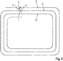
- Fig 2 shows a harvesting vehicle 1 harvesting a field 4 in spiral lanes 12, 13, 14. After the first circumnavigation of the field 4, the second lane 13 is driven parallel to the first lane 12 at a distance of the working width of the harvesting device 3. A transport vehicle 9 traveling in the first lane 12 drives parallel to the harvesting vehicle 1 while the harvesting vehicle 1 loads the harvested crop by means of the transfer device 10.
- a location system 7 records the lane 12 of the harvesting vehicle 1.
- the recorded lane is transmitted from the harvesting vehicle 1 to the transport vehicle 9 by means of a communication system 8.
- the transport vehicle 9 follows the transmitted lane by means of a location system 7 and an automatic steering system.
- the transfer distance of the transfer device 10 corresponds to the working width of the harvesting device 3. Since the transport vehicle 9 drives in the same lane 12 as the previous harvesting vehicle 1, the soil is only compacted there and a large part of the field 4 is spared.
- the system according to the invention shown consists of a harvesting vehicle 1 and a transport vehicle 9, which in this example is a tractor 15 with a trailer 16.
- the harvesting vehicle 1 is equipped with a location system 7.
- the location system 7 comprises a GNSS receiver and determines the current position of the harvesting vehicle 1 at regular intervals.
- the location system 7 generates the lane 5 of the harvesting vehicle 1 from a large number of positions and records the lane 5.
- the harvesting vehicle 1 comprises a communication system 7 with which the lane 5 is connected to a communication system 8 of the Tractor 15 is transmitted.
- the tractor 15 can thereby drive along the lane 5 of the harvesting vehicle 1.
- the harvesting vehicle 1 is equipped with a harvesting device 3. With the harvesting device 3, crops are harvested from the field and picked up by the harvesting vehicle 1.
- the harvesting vehicle 1 is equipped with a transfer device 10. By means of the transfer device 10, crop is transferred from the harvesting vehicle 1 to the trailer 16.
- the harvesting vehicle 1 is equipped with an automated steering system 17. With the automated steering system 17, the harvesting vehicle 1 can follow a predetermined lane 5. It should be noted that the predefined lane of the harvesting vehicle 1 does not have to correspond to the lane recorded with the location determination system 7. The recorded lane is transmitted to the transport vehicle and not the specified lane.
- the transport vehicle 9 is also equipped with an automated steering system 17. With the automated steering system 17, the transport vehicle 9 can follow the lane 5 transmitted by the harvesting vehicle 1.
- the distance 18 between the vehicles advantageously corresponds to the transfer distance of the transfer device 10.
- the distance 18 between the vehicles advantageously does not vary more than the width 19 of the receiving opening of the transport vehicle 9. If the distance 18 between the vehicles corresponds to the width of the harvesting device 3, see above
- the transport vehicle 9 travels essentially without deviations in an earlier lane of the harvesting vehicle 1.
- the longitudinal displacement 20 between the transport vehicle 9 and the harvesting vehicle 1 results from the distances between the receiver of the positioning system 7 on the transporting vehicle 9 and the center of the receiving opening on the one hand and the receiver of the positioning system 7 on the harvesting vehicle 1 and the transfer device 10 on the other hand.
- the longitudinal displacement 20 advantageously does not vary more than the length 21 of the receiving opening of the transport vehicle 9.
Landscapes
- Engineering & Computer Science (AREA)
- Life Sciences & Earth Sciences (AREA)
- Radar, Positioning & Navigation (AREA)
- Environmental Sciences (AREA)
- Remote Sensing (AREA)
- General Physics & Mathematics (AREA)
- Aviation & Aerospace Engineering (AREA)
- Physics & Mathematics (AREA)
- Automation & Control Theory (AREA)
- Soil Sciences (AREA)
- Mechanical Engineering (AREA)
- Guiding Agricultural Machines (AREA)
- Control Of Position, Course, Altitude, Or Attitude Of Moving Bodies (AREA)
Abstract
Description
- Die Erfindung bezieht sich auf ein Verfahren zum Überladen von Erntegut von einem Erntefahrzeug auf ein Transportfahrzeug.
- Aus der
WO2012110545 ist ein Verfahren zum Überladen von Erntegut bekannt. Dabei wird ein Referenzpfad aufgezeichnet und dazu parallele Pfade erzeugt. Wenn das Erntefahrzeug einen der Pfade abfährt wird für das Transportfahrzeug ein angepasster Pfad erzeugt. Nachteilig an dem Verfahren ist, dass ein großer Rechenaufwand zur Erzeugung der Pfade erforderlich ist. - Aufgabe der Erfindung ist es ein vereinfachtes Verfahren bereitzustellen.
- Gelöst wird die Aufgabe durch ein Verfahren zum Überladen von Erntegut von einem Erntefahrzeug auf ein Transportfahrzeug, wobei das Erntefahrzeug eine Vielzahl im Wesentlichen paralleler Fahrspuren abfährt, wobei die Fahrspur des Erntefahrzeugs während der Fahrt aufgezeichnet wird, wobei das Erntefahrzeug während der Fahrt Erntegut aufnimmt, wobei das Transportfahrzeug parallel zum Erntefahrzeug gefahren wird und während der Parallelfahrt von Erntefahrzeug und Transportfahrzeug das Erntegut vom Erntefahrzeug auf das Transportfahrzeug überladen wird, wobei die aufgezeichnete Fahrspur dem Transportfahrzeug übermittelt wird, wobei das Transportfahrzeug im Wesentlichen entlang der übermittelten Fahrspur gefahren wird.
- Erfindungsgemäß wird die vom Erntefahrzeug aufgezeichnete Fahrspur direkt als Vorgabespur für das Transportfahrzeug genutzt. Es entfällt der Aufwand für das Transportfahrzeug eigene Fahrspuren zu berechnen. Da das Erntefahrzeug parallele Fahrspuren abfährt ist dadurch die Vorgabespur für das Transportfahrzeug parallel zur Fahrspur des Erntefahrzeugs. Unter einer Parallelfahrt von Erntefahrzeug und Transportfahrzeug wird im Sinne der Erfindung verstanden, dass beide Fahrzeug im Wesentlichen nebeneinander fahren. Die Geschwindigkeiten der Fahrzeuge werden also aneinander angeglichen. Falls das Erntefahrzeug die aktuelle Fahrspur in umgekehrter Richtung zur Vorgabespur des Transportfahrzeugs befährt, so fährt das Transportfahrzeug die Vorgabespur in umgekehrter Richtung ab.
- In einer vorteilhaften Ausgestaltung überwacht ein Überwachungssystem die Relativposition von Erntefahrzeug und Transportfahrzeug, wobei das Überwachungssystem eine Geschwindigkeitsänderungsvorgabe an das Erntefahrzeug und/oder das Transportfahrzeug ausgibt, wenn die Parallelität von Erntefahrzeug und Transportfahrzeug um mehr als einen vorgegebenen Grenzwert abweicht. Das Überwachungssystem kann bspw. ein Kamerasystem an dem Erntefahrzeug umfassen, wobei das Kamerasystem die Relativgeschwindigkeit des Transportfahrzeugs ermittelt. Alternativ können die Geschwindigkeiten der beiden Fahrzeuge, bspw. mittels GNSS-Empfänger auf den Fahrzeugen, ermittelt und verglichen werden. Weitere Möglichkeiten sind die Ermittlungen der Geschwindigkeiten aus den Radgeschwindigkeiten und Durchmessern oder Radarmessungen zur Bestimmung der Relativgeschwindigkeit. Die Richtung der Geschwindigkeit wird bevorzugt direkt aus der Messung bestimmt. Alternativ kann die Richtung mit Trägheitssensoren oder aus Lenkwinkelsensoren bestimmt werden.
- In einer Ausgestaltung ist das Erntefahrzeug mit einem Ortsbestimmungssystem, bevorzugt einem GNSS-Empfänger, ausgestattet und aus den vom Ortsbestimmungssystem bestimmten Ortsdaten die Fahrspur generiert wird. Das Ortsbestimmungssystem bestimmt in regelmäßigen oder unregelmäßigen Abständen die aktuelle Position des Erntefahrzeugs. Aus der Liste der Ortspositionen wird dann die Fahrspur generiert. Die Fahrspur kann direkt aus den Ortspositionen generiert werden oder aus einer Interpolation. Eine Interpolation glättet die Fahrspur und gleicht Ungenauigkeiten der Ortsbestimmungen aus. Ungewöhnliche Fahrmanöver wie ein kurzes Rückwärtsfahren bspw. wegen einer Verstopfung eines Arbeitsaggregates der Erntemaschine können bei der Generierung der Fahrspur entfernt werden.
- In einer vorteilhaften Ausgestaltung vergleicht das Ortsbestimmungssystem die aktuelle Fahrspur mit einer übermittelten Fahrspur und gibt eine Warnung aus, wenn die Parallelität der aktuellen Fahrspur von der übermittelten Fahrspur um mehr als einen vorbestimmten Grenzwert abweicht. Wenn die aktuelle Fahrspur nicht parallel zur übermittelten Fahrspur ist, fährt das Transportfahrzeug nicht parallel zum Erntefahrzeug. Wird die Abweichung zu groß, so ist ein Überladen des Ernteguts nicht möglich.
- Da die Fahrspur des Transportfahrzeugs bekannt ist, nämlich die übermittelte Fahrspur, ist eine Überwachung des Abstandes zwischen den Fahrzeugen nicht notwendig. Wenn das Erntefahrzeug nicht parallel zur übermittelten Fahrspur fährt ist dies gleichbedeutend mit einem fehlerhaften Abstand zum Transportfahrzeug. Dadurch kann ein Abstandmesssystem zur Abstandskontrolle zwischen den Fahrzeugen eingespart werden.
- In einer vorteilhaften Ausgestaltung umfasst das Transportfahrzeug ein Ortsbestimmungssystem und ein automatisiertes Lenksystem, wobei das Lenksystem das Transportfahrzeug entlang der übermittelten Fahrspur lenkt. Das Ortbestimmungssystem überprüft ob sich das Transportfahrzeug auf der übermittelten Fahrspur befindet und gibt bei einer Abweichung entsprechende Signale an das Lenksystem ab. Das Lenksystem kann das Transportfahrzeug so automatisiert entlang der übermittelten Fahrspur lenken. Der Fahrer des Transportfahrzeugs wird dadurch entlastet.
- In einer alternativen Ausgestaltung umfasst das Transportfahrzeig ein Ortsbestimmungssystem und die übermittelte Fahrspur wird einem Fahrer des Transportfahrzeugs visuell angezeigt. Das Ortbestimmungssystem überprüft ob sich das Transportfahrzeug auf der übermittelten Fahrspur befindet und zeigt bei einer Abweichung dem Fahrer an wie er lenken muss um der übermittelten Fahrspur zu folgen.
- In einer vorteilhaften Ausgestaltung wird das Transportfahrzeug im Wesentlichen abweichungslos in der Fahrspur des Erntefahrzeugs gefahren. Durch das Fahren des Erntefahrzeugs in der Fahrspur des Erntefahrzeugs wird der Boden nur in einer Fahrspur verdichtet und nicht in zwei Fahrspuren von Erntefahrzeug und Transportfahrzeug getrennt. Das schont den Boden und es wird weniger Aufwand zur Lockerung des Bodens notwendig.
- In einer alternativen Ausgestaltung wird die aufgezeichnete Fahrspur vor der Übermittlung an das Transportfahrzeug um einen Offset quer zur Fahrtrichtung versetzt. Die Versetzung um einen Offset kann notwendig sein, wenn die Abstände zwischen den parallelen Fahrspuren kein Überladen von Erntegut ermöglichen. Das Addieren eines Offsets ermöglicht die Nutzung der aufgezeichneten Fahrspur mit minimalem Aufwand.
- In einer Weiterbildung umfass das Erntefahrzeug ein Arbeitsaggregat mit einer Arbeitsbreite und eine Überladevorrichtung mit einer Überladeentfernung, wobei der Offset aus einer Differenz der Arbeitsbreite und der Überladeentfernung bestimmt wird. Die Arbeitsbreite bestimmt die Abstände zwischen den parallelen Fahrspuren. Die Überladeentfernung bestimmt den Abstand zwischen Transportfahrzeug und Erntefahrzeug. Falls die Arbeitsbreite nicht der Überladeentfernung entspricht, wird der Offset um den die Fahrspur versetzt werden muss aus der Differenz von Arbeitsbreite und Überladeentfernung bestimmt werden. Die Bestimmung des Offsets geschieht vorzugsweise automatisch auf dem Erntefahrzeug, dadurch sind auf dem Transportfahrzeug keine Informationen über die Arbeitsbreite oder die Überladeentfernung notwendig.
- Die Erfindung betrifft auch ein System zum Überladen von Erntegut, bestehend aus einem Erntefahrzeug und einem Transportfahrzeug, wobei das Erntefahrzeug und das Transportfahrzeug mit einem Ortsbestimmungssystem, bevorzugt einem GNSS-Empfänger, ausgestattet sind, wobei das Ortsbestimmungssystem des Erntefahrzeugs dazu vorgesehen und eingerichtet ist eine Fahrspur des Erntefahrzeugs aufzuzeichnen, wobei das Erntefahrzeug mit einer Überladevorrichtung ausgestattet ist, wobei die Überladevorrichtung dazu vorgesehen und eingerichtet ist während einer Parallelfahrt von Erntefahrzeug und Transportfahrzeug Erntegut vom Erntefahrzeug zum Transportfahrzeug zu überladen, wobei das Erntefahrzeug und das Transportfahrzeug mit jeweils einem Kommunikationssystem ausgestattet sind, wobei die Kommunikationssysteme dazu vorgesehen und eingerichtet sind die aufgezeichnete Fahrspur an das Transportfahrzeug zu übermitteln, wobei das Ortsbestimmungssystem des Transportfahrzeugs dazu vorgesehen und eingerichtet ist ein Abweichung eine aktuellen Position des Transportfahrzeugs von der übermittelten Fahrspur zu erkennen und auszugeben.
- Das System ermöglicht eine besonders einfache Steuerung des Transportfahrzeugs entlang der Fahrspur des Erntefahrzeugs.
- In einer Ausgestaltung ist das Erntefahrzeug ein Mähdrescher oder ein Feldhäcksler.
- In einer Weiterbildung umfasst das Transportfahrzeug ein automatisiertes Lenksystem, wobei das Lenksystem mit dem Ortsbestimmungssystem des Transportfahrzeugs verbunden ist, wobei die Ausgabe des Ortsbestimmungssystems des Transportfahrzeugs an das Lenksystem weitergeleitet wird. Das Lenksystem kann durch die Verbindung zum Ortsbestimmungssystem das Transportfahrzeug automatisiert entlang der übermittelten Fahrspur lenken.
- Die Erfindung wird im Folgenden an Ausführungsbeispielen näher erläutert. Dabei zeigt
-
Fig 1 ein Verfahren mit mäandernden Fahrspuren, -
Fig 2 ein Verfahren mit spiralförmigen Fahrspuren, -
Fig 3 ein erfindungsgemäßes System. -
Fig 1 zeigt ein Erntefahrzeug 1, in diesem Beispiel einen Feldhäcksler 2. Der Feldhäcksler 2 ist mit einer Erntevorrichtung 3 ausgestattet und erntet ein Feld 4 in mäandernden Fahrspuren 5 ab. Die Fahrspuren 5 müssen dabei nicht vor der Fahrt feststehen. Die Fahrspuren 5 sind in diesem Beispiel in dem Bereich des Feldes 4 jeweils eine Gerade 6. Im Bereich des Vorgewendes wendet der Feldhäcksler 2. Die geraden Fahrspuren 6 sind dabei parallel zueinander, wobei der Abstand zwischen den geraden Fahrspuren 6 der Arbeitsbreite der Erntevorrichtung 3 entspricht. - Der Feldhäcksler 2 ist mit einem Ortsbestimmungssystem 7 ausgestattet. Das Ortsbestimmungssystem 7 zeichnet die Fahrspuren des Feldhäcksler 2 auf. Die geraden Fahrspuren 6 werden mittels eines Kommunikationssystem 8 vom Feldhäcksler 2 zu einem Transportfahrzeug 9 übertragen. Da in diesem Beispiel die Länge der Überladevorrichtung 10 des Feldhäcksler 2 nicht der Arbeitsbreite der Erntevorrichtung 3 entspricht wird die aufgezeichnete Fahrspur vor der Übermittlung an das Transportfahrzeug 9 um einen Offset 11 quer zur Fahrtrichtung versetzt. Das Transportfahrzeug 9 fährt entlang der übertragenen geraden Fahrspuren 6a parallel zum Feldhäcksler 2.
- Würde die Überladeentfernung der Überladevorrichtung 10 der Arbeitsbreite der Erntevorrichtung 3 entsprechen, würde auf den Offset verzichtet werden und das Transportfahrzeug 9 würde die selben geraden Fahrspuren 6 nutzen wie das Erntefahrzeug 1.
- In der ersten geraden Fahrspur 6 überlädt der Feldhäcksler 2 das Erntegut nach hinten, da neben ihm kein Platz ist. Ab der zweiten geraden Fahrspur 6 fährt ein Transportfahrzeug 9 jeweils parallel zum Feldhäcksler 2 auf der jeweils davor abgeernteten geraden Fahrspur 6a neben dem Feldhäcksler 2 und der Feldhäcksler 2 überlädt das Erntegut auf das Transportfahrzeug 9. Da der Feldhäcksler 2 die geraden Fahrspuren 6 in abwechselnden Richtungen befährt, fährt das Transportfahrzeug 9 die Fahrspuren 6a in der jeweils anderen Richtung ab.
-
Fig 2 zeigt ein Erntefahrzeug 1, das ein Feld 4 in spiralförmigen Fahrspuren 12, 13, 14 aberntet. Nach der ersten Umrundung des Feldes 4 wird die zweite Fahrspur 13 parallel zur ersten Fahrspur 12 im Abstand der Arbeitsbreite der Erntevorrichtung 3 gefahren. Ein in der ersten Fahrspur 12 fahrendes Transportfahrzeug 9 fährt parallel zum Erntefahrzeug 1 während das Erntefahrzeug 1 das Erntegut mittels der Überladevorrichtung 10 überlädt. - Ebenso wie in
Figur 1 zeichnet ein Ortsbestimmungssystem 7 die Fahrspur 12 des Erntefahrzeugs 1 auf. Die aufgezeichnete Fahrspur wird mittels eines Kommunikationssystem 8 vom Erntefahrzeug 1 zum Transportfahrzeug 9 übertragen. Das Transportfahrzeug 9 folgt der übertragenen Fahrspur mittels eines Ortsbestimmungssystem 7 und eines automatischen Lenksystems. - In diesem Beispiel entspricht die Überladeentfernung der Überladevorrichtung 10 der Arbeitsbreite der Erntevorrichtung 3. Da das Transportfahrzeug 9 in derselben Fahrspur 12 fährt wie zuvor das Erntefahrzeug 1 wird der Boden nur dort verdichtet und ein großer Teil des Feldes 4 geschont.
- Das in
Fig 3 gezeigte erfindungsgemäße System besteht aus einem Erntefahrzeug 1 und einem Transportfahrtzeug 9, welches in diesem Beispiel ein Traktor 15 mit einem Anhänger 16 ist. Das Erntefahrzeug 1 ist mit einem Ortsbestimmungssystem 7 ausgestattet. Das Ortsbestimmungssystem 7 umfasst einen GNSS-Empfänger und bestimmt in regelmäßigen Abständen die aktuelle Position des Erntefahrzeugs 1. Aus einer Vielzahl von Positionen generiert das Ortsbestimmungssystem 7 die Fahrspur 5 des Erntefahrzeugs 1 und zeichnet die Fahrspur 5 auf. Das Erntefahrzeug 1 umfasst ein Kommunikationssystem 7 mit dem die Fahrspur 5 an ein Kommunikationssystem 8 des Traktors 15 übermittelt wird. Der Traktor 15 kann dadurch die Fahrspur 5 Erntefahrzeug 1 entlangfahren. - Das Erntefahrzeug 1 ist mit einer Erntevorrichtung 3 ausgestattet. Mit der Erntevorrichtung 3 wird Erntegut vom Feld geerntet und vom Erntefahrzeug 1 aufgenommen. Das Erntefahrzeug 1 ist mit einer Überladevorrichtung 10 ausgestattet. Mittels der Überladevorrichtung 10 wird Erntegut vom Erntefahrzeug 1 auf den Anhänger 16 überladen.
- Das Erntefahrzeug 1 ist mit einem automatisierten Lenksystem 17 ausgestattet. Mit dem automatisierten Lenksystem 17 kann das Erntefahrzeug 1 einer vorgegebene Fahrspur 5 folgen. Es sei angemerkt, dass die vorgegebene Fahrspur des Erntefahrzeugs 1 nicht der mit dem Ortsbestimmungssystem 7 aufgezeichneten Fahrspur entsprechen muss. An das Transportfahrzeug wird die aufgezeichnete Fahrspur übermittelt und nicht die vorgegebene Fahrspur.
- Das Transportfahrzeug 9 ist ebenfalls mit einem automatisierten Lenksystem 17 ausgestattet. Mit dem automatisierten Lenksystem 17 kann das Transportfahrzeug 9 der vom Erntefahrzeug 1 übertragenen Fahrspur 5 folgen.
- Der Abstand 18 zwischen den Fahrzeugen entspricht vorteilhafter Weise der Überladeentfernung der Überladevorrichtung 10. Der Abstand 18 zwischen den Fahrzeugen variiert vorteilhafter Weise nicht mehr als die Breite 19 der Aufnahmeöffnung des Transportfahrzeugs 9. Entspricht der Abstand 18 zwischen den Fahrzeugen der Breite der Erntevorrichtung 3, so fährt das Transportahrzeug 9 im Wesentlichen abweichungslos in einer früheren Fahrspur des Erntefahrzeugs 1.
- Die Längsverschiebung 20 zwischen Transportfahrzeug 9 und Erntefahrzeug 1 ergibt sich aus den Abständen zwischen dem Empfänger des Ortsbestimmungssystems 7 am Transportfahrzeug 9 und der Mitte der Aufnahmeöffnung einerseits und dem Empfänger des Ortsbestimmungssystem 7 am Erntefahrzeug 1 und der Überladevorrichtung 10 andererseits. Die Längsverschiebung 20 variiert vorteilhafter Weise nicht mehr als die Länge 21 der Aufnahmeöffnung des Transportfahrzeugs 9.
-
- 1
- Erntefahrzeug
- 2
- Feldhäcksler
- 3
- Erntevorrichtung
- 4
- Feld
- 5, 5a
- Fahrspur
- 6, 6a
- Parallele Fahrspuren
- 7
- Ortsbestimmungssystem
- 8
- Kommunikationssystem
- 9
- Transportfahrzeug
- 10
- Überladevorrichtung
- 11
- Offset
- 12
- Erste Fahrspur
- 13
- Zweite Fahrspur
- 14
- Dritte Fahrspur
- 15
- Traktor
- 16
- Anhänger
- 17
- Automatisiertes Lenksystem
- 18
- Fahrzeugabstand
- 19
- Breite der Aufnahmeöffnung
- 20
- Längsverschiebung
- 21
- Länge der Aufnahmeöffnung
Claims (12)
- Verfahren zum Überladen von Erntegut von einem Erntefahrzeug (1) auf ein Transportfahrzeug (9),
wobei das Erntefahrzeug (1) eine Vielzahl im Wesentlichen paralleler Fahrspuren (6) abfährt,
wobei die Fahrspur (6) des Erntefahrzeugs (1) während der Fahrt aufgezeichnet wird,
wobei das Erntefahrzeug (1) während der Fahrt Erntegut aufnimmt,
wobei das Transportfahrzeug (9) parallel zum Erntefahrzeug (1) gefahren wird und während der Parallelfahrt von Erntefahrzeug (1) und Transportfahrzeug (9) das Erntegut vom Erntefahrzeug (1) auf das Transportfahrzeug (9) überladen wird, dadurch gekennzeichnet, dass die aufgezeichnete Fahrspur (6) dem Transportfahrzeug (9) übermittelt wird,
wobei das Transportfahrzeug (9) im Wesentlichen entlang der übermittelten Fahrspur (6) gefahren wird. - Verfahren nach Anspruch 1, dadurch gekennzeichnet, dass ein Überwachungssystem die Relativosition von Erntefahrzeug (1) und Transportfahrzeug (9) überwacht, wobei das Überwachungssystem eine Geschwindigkeitsänderungsvorgabe an das Erntefahrzeug (1) und/oder das Transportfahrzeug (9) ausgibt, wenn die Parallelität von Erntefahrzeug (1) und Transportfahrzeug (9) um mehr als einen vorgegebenen Grenzwert abweicht.
- Verfahren nach einem der vorhergehenden Ansprüche, dadurch gekennzeichnet, dass das Erntefahrzeug mit einem Ortsbestimmungssystem(7), bevorzugt einem GNSS-Empfänger, ausgestattet ist und aus den vom Ortsbestimmungssystem (7) bestimmten Ortsdaten die Fahrspur (5, 6) generiert wird.
- Verfahren nach Anspruch 3, dadurch gekennzeichnet, dass das Ortsbestimmungssystem (7) die aktuelle Fahrspur (6) mit einer übermittelten Fahrspur (6a) vergleicht und eine Warnung ausgibt, wenn die Parallelität der aktuellen Fahrspur (6) von der übermittelten Fahrspur (6a) um mehr als einen vorbestimmten Grenzwert abweicht.
- Verfahren nach einem der vorhergehenden Ansprüche, dadurch gekennzeichnet, dass das Transportfahrzeug (9) ein Ortsbestimmungssystem (7) und ein automatisiertes Lenksystem (17) umfasst, wobei das Lenksystem (17) das Transportfahrzeug (9) entlang der übermittelten Fahrspur (6a) lenkt.
- Verfahren nach einem der Ansprüche 1bis 4, dadurch gekennzeichnet, dass das Transportfahrzeig (9) ein Ortsbestimmungssystem (7) umfasst und die übermittelte Fahrspur (6a) einem Fahrer des Transportfahrzeugs (9) visuell angezeigt wird.
- Verfahren nach einem der vorhergehenden Ansprüche, dadurch gekennzeichnet, dass das Transportfahrzeug (9) im Wesentlichen abweichungslos in der Fahrspur (6) des Erntefahrzeugs (1) gefahren wird.
- Verfahren nach einem der Ansprüche 1 bis 6, dadurch gekennzeichnet, dass die aufgezeichnete Fahrspur (6) vor der Übermittlung an das Transportfahrzeug (9) um einen Offset (11) quer zur Fahrtrichtung versetzt wird.
- Verfahren nach Anspruch 8, dadurch gekennzeichnet, dass das Erntefahrzeug (1) ein Arbeitsaggregat (3) mit einer Arbeitsbreite und eine Überladevorrichtung (10) mit einer Überladeentfernung umfasst, wobei der Offset (11) aus einer Differenz der Arbeitsbreite und der Überladeentfernung bestimmt wird.
- System zum Überladen von Erntegut, bestehend aus einem Erntefahrzeug (1) und einem Transportfahrzeug (9), wobei das Erntefahrzeug (1) und das Transportfahrzeug (9) mit einem Ortsbestimmungssystem (7), bevorzugt einem GNSS-Empfänger, ausgestattet sind, wobei das Ortsbestimmungssystem (7) des Erntefahrzeugs (1) dazu vorgesehen und eingerichtet ist eine Fahrspur (5, 6) des Erntefahrzeugs (1) aufzuzeichnen, wobei das Erntefahrzeug (1) mit einer Überladevorrichtung (10) ausgestattet ist, wobei die Überladevorrichtung (10) dazu vorgesehen und eingerichtet ist während einer Parallelfahrt von Erntefahrzeug (1) und Transportfahrzeug (9) Erntegut vom Erntefahrzeug (1) zum Transportfahrzeug (9) zu überladen, dadurch gekennzeichnet, dass das Erntefahrzeug (1) und das Transportfahrzeug (9) mit jeweils einem Kommunikationssystem (8) ausgestattet sind, wobei die Kommunikationssysteme (8) dazu vorgesehen und eingerichtet sind die aufgezeichnete Fahrspur (6) an das Überladefahrzeug (9) zu übermitteln, wobei das Ortsbestimmungssystem (7) des Transportfahrzeugs (9) dazu vorgesehen und eingerichtet ist ein Abweichung eine aktuellen Position des Transportfahrzeugs (9) von der übermittelten Fahrspur (6a) zu erkennen und auszugeben.
- System nach Anspruch 10, dadurch gekennzeichnet, dass das Erntefahrzeug (1) ein Mähdrescher oder ein Feldhäcksler (2) ist.
- System nach einem der Ansprüche 10 oder 11, dadurch gekennzeichnet, dass das Transportfahrzeug (9) ein automatisiertes Lenksystem umfasst, wobei das Lenksystem mit dem Ortsbestimmungssystem (7) des Transportfahrzeugs (9) verbunden ist, wobei die Ausgabe des Ortsbestimmungssystems (7) des Transportfahrzeugs (9) an das Lenksystem weitergeleitet wird.
Applications Claiming Priority (1)
| Application Number | Priority Date | Filing Date | Title |
|---|---|---|---|
| DE102020100299.8A DE102020100299A1 (de) | 2020-01-09 | 2020-01-09 | Verfahren und System zum Überladen von Erntegut |
Publications (2)
| Publication Number | Publication Date |
|---|---|
| EP3847878A1 true EP3847878A1 (de) | 2021-07-14 |
| EP3847878B1 EP3847878B1 (de) | 2024-02-14 |
Family
ID=72811658
Family Applications (1)
| Application Number | Title | Priority Date | Filing Date |
|---|---|---|---|
| EP20200734.0A Active EP3847878B1 (de) | 2020-01-09 | 2020-10-08 | Verfahren und system zum überladen von erntegut |
Country Status (2)
| Country | Link |
|---|---|
| EP (1) | EP3847878B1 (de) |
| DE (1) | DE102020100299A1 (de) |
Cited By (8)
| Publication number | Priority date | Publication date | Assignee | Title |
|---|---|---|---|---|
| US12082531B2 (en) | 2022-01-26 | 2024-09-10 | Deere & Company | Systems and methods for predicting material dynamics |
| EP4256918A4 (de) * | 2020-12-02 | 2024-11-06 | Yanmar Holdings Co., Ltd. | Mähdrescher und fahrsteuerungsverfahren |
| US12298767B2 (en) | 2022-04-08 | 2025-05-13 | Deere & Company | Predictive material consumption map and control |
| US12433194B2 (en) | 2022-08-11 | 2025-10-07 | Deere & Company | Systems and methods for predictive harvesting logistics |
| US12457929B2 (en) | 2022-08-11 | 2025-11-04 | Deere & Company | Systems and methods for predictive harvesting logistics |
| US12520759B2 (en) | 2022-01-26 | 2026-01-13 | Deere & Company | Systems and methods for predicting material dynamics |
| US12604791B2 (en) | 2022-07-06 | 2026-04-21 | Deere & Company | Machine control based upon estimated operator skill level trend |
| US12682406B2 (en) | 2022-07-08 | 2026-07-14 | Deere & Company | Agricultural system control based on progressive time horizon model output |
Families Citing this family (1)
| Publication number | Priority date | Publication date | Assignee | Title |
|---|---|---|---|---|
| US12317776B2 (en) | 2021-11-09 | 2025-06-03 | Deere & Company | Harvesting machine haulage vehicle coordination control |
Citations (6)
| Publication number | Priority date | Publication date | Assignee | Title |
|---|---|---|---|---|
| DE10064862A1 (de) * | 2000-12-23 | 2002-07-11 | Claas Selbstfahr Erntemasch | Vorrichtung und Verfahren zur Koordination und Einstellung von landwirtschaftlichen Fahrzeugen |
| DE102005047306A1 (de) * | 2005-09-30 | 2007-04-12 | Claas Saulgau Gmbh | Landwirtschaftliche Arbeitseinheit mit einem Arbeitsaggregat zum Erzeugen einer Objektreihe |
| DE102007016670A1 (de) * | 2007-04-04 | 2008-10-09 | Claas Selbstfahrende Erntemaschinen Gmbh | Selbstfahrende landwirtschaftliche Erntemaschine mit steuerbarer Überladeeinrichtung |
| EP2100495A1 (de) * | 2008-03-13 | 2009-09-16 | CLAAS Selbstfahrende Erntemaschinen GmbH | Landwirtschaftliche Erntemaschine mit einer Überladeeinrichtung |
| DE102010043854A1 (de) * | 2010-11-12 | 2012-05-16 | Deere & Company | Steueranordnung zur Kontrolle des Überladens landwirtschaftlichen Ernteguts von einer Erntemaschine auf ein Transportfahrzeug |
| WO2012110545A1 (en) | 2011-02-18 | 2012-08-23 | Cnh Belgium N.V. | System and method for synchronized control of a harvester and transport vehicle |
-
2020
- 2020-01-09 DE DE102020100299.8A patent/DE102020100299A1/de active Pending
- 2020-10-08 EP EP20200734.0A patent/EP3847878B1/de active Active
Patent Citations (6)
| Publication number | Priority date | Publication date | Assignee | Title |
|---|---|---|---|---|
| DE10064862A1 (de) * | 2000-12-23 | 2002-07-11 | Claas Selbstfahr Erntemasch | Vorrichtung und Verfahren zur Koordination und Einstellung von landwirtschaftlichen Fahrzeugen |
| DE102005047306A1 (de) * | 2005-09-30 | 2007-04-12 | Claas Saulgau Gmbh | Landwirtschaftliche Arbeitseinheit mit einem Arbeitsaggregat zum Erzeugen einer Objektreihe |
| DE102007016670A1 (de) * | 2007-04-04 | 2008-10-09 | Claas Selbstfahrende Erntemaschinen Gmbh | Selbstfahrende landwirtschaftliche Erntemaschine mit steuerbarer Überladeeinrichtung |
| EP2100495A1 (de) * | 2008-03-13 | 2009-09-16 | CLAAS Selbstfahrende Erntemaschinen GmbH | Landwirtschaftliche Erntemaschine mit einer Überladeeinrichtung |
| DE102010043854A1 (de) * | 2010-11-12 | 2012-05-16 | Deere & Company | Steueranordnung zur Kontrolle des Überladens landwirtschaftlichen Ernteguts von einer Erntemaschine auf ein Transportfahrzeug |
| WO2012110545A1 (en) | 2011-02-18 | 2012-08-23 | Cnh Belgium N.V. | System and method for synchronized control of a harvester and transport vehicle |
Cited By (8)
| Publication number | Priority date | Publication date | Assignee | Title |
|---|---|---|---|---|
| EP4256918A4 (de) * | 2020-12-02 | 2024-11-06 | Yanmar Holdings Co., Ltd. | Mähdrescher und fahrsteuerungsverfahren |
| US12082531B2 (en) | 2022-01-26 | 2024-09-10 | Deere & Company | Systems and methods for predicting material dynamics |
| US12520759B2 (en) | 2022-01-26 | 2026-01-13 | Deere & Company | Systems and methods for predicting material dynamics |
| US12298767B2 (en) | 2022-04-08 | 2025-05-13 | Deere & Company | Predictive material consumption map and control |
| US12604791B2 (en) | 2022-07-06 | 2026-04-21 | Deere & Company | Machine control based upon estimated operator skill level trend |
| US12682406B2 (en) | 2022-07-08 | 2026-07-14 | Deere & Company | Agricultural system control based on progressive time horizon model output |
| US12433194B2 (en) | 2022-08-11 | 2025-10-07 | Deere & Company | Systems and methods for predictive harvesting logistics |
| US12457929B2 (en) | 2022-08-11 | 2025-11-04 | Deere & Company | Systems and methods for predictive harvesting logistics |
Also Published As
| Publication number | Publication date |
|---|---|
| EP3847878B1 (de) | 2024-02-14 |
| DE102020100299A1 (de) | 2021-07-15 |
Similar Documents
| Publication | Publication Date | Title |
|---|---|---|
| EP3847878B1 (de) | Verfahren und system zum überladen von erntegut | |
| EP2130423B1 (de) | Landwirtschaftliches Fahrzeug und Betriebsverfahren dafür | |
| EP1795986B1 (de) | Routenplanungssystem für landwirtschaftliche Arbeitsmaschinen | |
| EP3781458B1 (de) | Verfahren zur kurvenradiusermittlung | |
| EP2508057B1 (de) | Vorrichtung und Verfahren zur Überwachung der Befahrbarkeit eines Bodens | |
| DE102011005400B4 (de) | Anordnung und Verfahren zur Abschätzung des Füllgrades beim Überladen landwirtschaftlichen Ernteguts von einer Erntemaschine auf ein Transportfahrzeug | |
| DE69114541T2 (de) | Verfahren und Gerät zur Einstellung eines Fahrzeugsensors. | |
| EP2936969B1 (de) | Kombination aus einem Zugfahrzeug und einer davon gezogenen Erntemaschine | |
| DE69407024T2 (de) | Steuerung zur Lenkung mit einem Leitdraht für ein von einem Benutzer gelenktes Transportfahrzeug | |
| DE10064862A1 (de) | Vorrichtung und Verfahren zur Koordination und Einstellung von landwirtschaftlichen Fahrzeugen | |
| EP3348130A1 (de) | Modellbasierte prädiktive geschwindigkeitskontrolle einer erntemaschine | |
| WO2020182564A1 (de) | Vision-basiertes lenkungsassistenzsystem für landfahrzeuge | |
| DE10209863B4 (de) | Verfahrbares Gestellsystem | |
| DE102009043060A1 (de) | System von mobilen Robotern mit einer Basisstation | |
| DE19508944A1 (de) | Selbstlenkvorrichtung | |
| DE3429184A1 (de) | Vorrichtung zur messung der masse eines kraftfahrzeuges | |
| DE102020203756A1 (de) | Autobahnausfahrt-erfassung und linienspiegelung zur fahrzeugtrajektorien-bestimmung | |
| EP4245108A1 (de) | Verfahren zur fahrroutenoptimierung | |
| EP4085741A1 (de) | Lenkverfahren für eine landmaschine | |
| EP4245107A1 (de) | Verfahren zur fahrroutenoptimierung | |
| DE102005004508A1 (de) | Vorrichtung zur gleichmäßigen Beschickung von Arbeitsmaschinen | |
| EP1769662A1 (de) | Landwirtschaftliche Arbeitseinheit mit einem Arbeitsaggregat zum Erzeugen einer Objektreihe | |
| EP4309480A1 (de) | Lenkverfahren für eine landmaschine | |
| EP1013159A2 (de) | Steuerung für landwirtschaftliche Arbeitsmaschine | |
| EP3750844B1 (de) | Flurförderzeug mit einer fahrzeugsteuerung für einen automatischen betrieb |
Legal Events
| Date | Code | Title | Description |
|---|---|---|---|
| PUAI | Public reference made under article 153(3) epc to a published international application that has entered the european phase |
Free format text: ORIGINAL CODE: 0009012 |
|
| STAA | Information on the status of an ep patent application or granted ep patent |
Free format text: STATUS: THE APPLICATION HAS BEEN PUBLISHED |
|
| AK | Designated contracting states |
Kind code of ref document: A1 Designated state(s): AL AT BE BG CH CY CZ DE DK EE ES FI FR GB GR HR HU IE IS IT LI LT LU LV MC MK MT NL NO PL PT RO RS SE SI SK SM TR |
|
| STAA | Information on the status of an ep patent application or granted ep patent |
Free format text: STATUS: REQUEST FOR EXAMINATION WAS MADE |
|
| 17P | Request for examination filed |
Effective date: 20220114 |
|
| RBV | Designated contracting states (corrected) |
Designated state(s): AL AT BE BG CH CY CZ DE DK EE ES FI FR GB GR HR HU IE IS IT LI LT LU LV MC MK MT NL NO PL PT RO RS SE SI SK SM TR |
|
| P01 | Opt-out of the competence of the unified patent court (upc) registered |
Effective date: 20230516 |
|
| GRAP | Despatch of communication of intention to grant a patent |
Free format text: ORIGINAL CODE: EPIDOSNIGR1 |
|
| STAA | Information on the status of an ep patent application or granted ep patent |
Free format text: STATUS: GRANT OF PATENT IS INTENDED |
|
| GRAS | Grant fee paid |
Free format text: ORIGINAL CODE: EPIDOSNIGR3 |
|
| INTG | Intention to grant announced |
Effective date: 20231211 |
|
| GRAA | (expected) grant |
Free format text: ORIGINAL CODE: 0009210 |
|
| STAA | Information on the status of an ep patent application or granted ep patent |
Free format text: STATUS: THE PATENT HAS BEEN GRANTED |
|
| AK | Designated contracting states |
Kind code of ref document: B1 Designated state(s): AL AT BE BG CH CY CZ DE DK EE ES FI FR GB GR HR HU IE IS IT LI LT LU LV MC MK MT NL NO PL PT RO RS SE SI SK SM TR |
|
| REG | Reference to a national code |
Ref country code: GB Ref legal event code: FG4D Free format text: NOT ENGLISH |
|
| REG | Reference to a national code |
Ref country code: CH Ref legal event code: EP |
|
| REG | Reference to a national code |
Ref country code: DE Ref legal event code: R096 Ref document number: 502020006997 Country of ref document: DE |
|
| REG | Reference to a national code |
Ref country code: IE Ref legal event code: FG4D Free format text: LANGUAGE OF EP DOCUMENT: GERMAN |
|
| REG | Reference to a national code |
Ref country code: LT Ref legal event code: MG9D |
|
| REG | Reference to a national code |
Ref country code: NL Ref legal event code: MP Effective date: 20240214 |
|
| PG25 | Lapsed in a contracting state [announced via postgrant information from national office to epo] |
Ref country code: IS Free format text: LAPSE BECAUSE OF FAILURE TO SUBMIT A TRANSLATION OF THE DESCRIPTION OR TO PAY THE FEE WITHIN THE PRESCRIBED TIME-LIMIT Effective date: 20240614 |
|
| PG25 | Lapsed in a contracting state [announced via postgrant information from national office to epo] |
Ref country code: LT Free format text: LAPSE BECAUSE OF FAILURE TO SUBMIT A TRANSLATION OF THE DESCRIPTION OR TO PAY THE FEE WITHIN THE PRESCRIBED TIME-LIMIT Effective date: 20240214 |
|
| PG25 | Lapsed in a contracting state [announced via postgrant information from national office to epo] |
Ref country code: GR Free format text: LAPSE BECAUSE OF FAILURE TO SUBMIT A TRANSLATION OF THE DESCRIPTION OR TO PAY THE FEE WITHIN THE PRESCRIBED TIME-LIMIT Effective date: 20240515 |
|
| PG25 | Lapsed in a contracting state [announced via postgrant information from national office to epo] |
Ref country code: HR Free format text: LAPSE BECAUSE OF FAILURE TO SUBMIT A TRANSLATION OF THE DESCRIPTION OR TO PAY THE FEE WITHIN THE PRESCRIBED TIME-LIMIT Effective date: 20240214 Ref country code: NL Free format text: LAPSE BECAUSE OF FAILURE TO SUBMIT A TRANSLATION OF THE DESCRIPTION OR TO PAY THE FEE WITHIN THE PRESCRIBED TIME-LIMIT Effective date: 20240214 Ref country code: RS Free format text: LAPSE BECAUSE OF FAILURE TO SUBMIT A TRANSLATION OF THE DESCRIPTION OR TO PAY THE FEE WITHIN THE PRESCRIBED TIME-LIMIT Effective date: 20240514 |
|
| PG25 | Lapsed in a contracting state [announced via postgrant information from national office to epo] |
Ref country code: ES Free format text: LAPSE BECAUSE OF FAILURE TO SUBMIT A TRANSLATION OF THE DESCRIPTION OR TO PAY THE FEE WITHIN THE PRESCRIBED TIME-LIMIT Effective date: 20240214 |
|
| PG25 | Lapsed in a contracting state [announced via postgrant information from national office to epo] |
Ref country code: RS Free format text: LAPSE BECAUSE OF FAILURE TO SUBMIT A TRANSLATION OF THE DESCRIPTION OR TO PAY THE FEE WITHIN THE PRESCRIBED TIME-LIMIT Effective date: 20240514 Ref country code: NO Free format text: LAPSE BECAUSE OF FAILURE TO SUBMIT A TRANSLATION OF THE DESCRIPTION OR TO PAY THE FEE WITHIN THE PRESCRIBED TIME-LIMIT Effective date: 20240514 Ref country code: NL Free format text: LAPSE BECAUSE OF FAILURE TO SUBMIT A TRANSLATION OF THE DESCRIPTION OR TO PAY THE FEE WITHIN THE PRESCRIBED TIME-LIMIT Effective date: 20240214 Ref country code: LT Free format text: LAPSE BECAUSE OF FAILURE TO SUBMIT A TRANSLATION OF THE DESCRIPTION OR TO PAY THE FEE WITHIN THE PRESCRIBED TIME-LIMIT Effective date: 20240214 Ref country code: IS Free format text: LAPSE BECAUSE OF FAILURE TO SUBMIT A TRANSLATION OF THE DESCRIPTION OR TO PAY THE FEE WITHIN THE PRESCRIBED TIME-LIMIT Effective date: 20240614 Ref country code: HR Free format text: LAPSE BECAUSE OF FAILURE TO SUBMIT A TRANSLATION OF THE DESCRIPTION OR TO PAY THE FEE WITHIN THE PRESCRIBED TIME-LIMIT Effective date: 20240214 Ref country code: GR Free format text: LAPSE BECAUSE OF FAILURE TO SUBMIT A TRANSLATION OF THE DESCRIPTION OR TO PAY THE FEE WITHIN THE PRESCRIBED TIME-LIMIT Effective date: 20240515 Ref country code: FI Free format text: LAPSE BECAUSE OF FAILURE TO SUBMIT A TRANSLATION OF THE DESCRIPTION OR TO PAY THE FEE WITHIN THE PRESCRIBED TIME-LIMIT Effective date: 20240214 Ref country code: ES Free format text: LAPSE BECAUSE OF FAILURE TO SUBMIT A TRANSLATION OF THE DESCRIPTION OR TO PAY THE FEE WITHIN THE PRESCRIBED TIME-LIMIT Effective date: 20240214 Ref country code: BG Free format text: LAPSE BECAUSE OF FAILURE TO SUBMIT A TRANSLATION OF THE DESCRIPTION OR TO PAY THE FEE WITHIN THE PRESCRIBED TIME-LIMIT Effective date: 20240214 |
|
| PG25 | Lapsed in a contracting state [announced via postgrant information from national office to epo] |
Ref country code: PL Free format text: LAPSE BECAUSE OF FAILURE TO SUBMIT A TRANSLATION OF THE DESCRIPTION OR TO PAY THE FEE WITHIN THE PRESCRIBED TIME-LIMIT Effective date: 20240214 Ref country code: PT Free format text: LAPSE BECAUSE OF FAILURE TO SUBMIT A TRANSLATION OF THE DESCRIPTION OR TO PAY THE FEE WITHIN THE PRESCRIBED TIME-LIMIT Effective date: 20240614 |
|
| PG25 | Lapsed in a contracting state [announced via postgrant information from national office to epo] |
Ref country code: SE Free format text: LAPSE BECAUSE OF FAILURE TO SUBMIT A TRANSLATION OF THE DESCRIPTION OR TO PAY THE FEE WITHIN THE PRESCRIBED TIME-LIMIT Effective date: 20240214 Ref country code: PT Free format text: LAPSE BECAUSE OF FAILURE TO SUBMIT A TRANSLATION OF THE DESCRIPTION OR TO PAY THE FEE WITHIN THE PRESCRIBED TIME-LIMIT Effective date: 20240614 Ref country code: PL Free format text: LAPSE BECAUSE OF FAILURE TO SUBMIT A TRANSLATION OF THE DESCRIPTION OR TO PAY THE FEE WITHIN THE PRESCRIBED TIME-LIMIT Effective date: 20240214 Ref country code: LV Free format text: LAPSE BECAUSE OF FAILURE TO SUBMIT A TRANSLATION OF THE DESCRIPTION OR TO PAY THE FEE WITHIN THE PRESCRIBED TIME-LIMIT Effective date: 20240214 |
|
| PG25 | Lapsed in a contracting state [announced via postgrant information from national office to epo] |
Ref country code: DK Free format text: LAPSE BECAUSE OF FAILURE TO SUBMIT A TRANSLATION OF THE DESCRIPTION OR TO PAY THE FEE WITHIN THE PRESCRIBED TIME-LIMIT Effective date: 20240214 |
|
| PG25 | Lapsed in a contracting state [announced via postgrant information from national office to epo] |
Ref country code: SM Free format text: LAPSE BECAUSE OF FAILURE TO SUBMIT A TRANSLATION OF THE DESCRIPTION OR TO PAY THE FEE WITHIN THE PRESCRIBED TIME-LIMIT Effective date: 20240214 |
|
| PG25 | Lapsed in a contracting state [announced via postgrant information from national office to epo] |
Ref country code: CZ Free format text: LAPSE BECAUSE OF FAILURE TO SUBMIT A TRANSLATION OF THE DESCRIPTION OR TO PAY THE FEE WITHIN THE PRESCRIBED TIME-LIMIT Effective date: 20240214 Ref country code: EE Free format text: LAPSE BECAUSE OF FAILURE TO SUBMIT A TRANSLATION OF THE DESCRIPTION OR TO PAY THE FEE WITHIN THE PRESCRIBED TIME-LIMIT Effective date: 20240214 |
|
| PG25 | Lapsed in a contracting state [announced via postgrant information from national office to epo] |
Ref country code: SK Free format text: LAPSE BECAUSE OF FAILURE TO SUBMIT A TRANSLATION OF THE DESCRIPTION OR TO PAY THE FEE WITHIN THE PRESCRIBED TIME-LIMIT Effective date: 20240214 |
|
| PG25 | Lapsed in a contracting state [announced via postgrant information from national office to epo] |
Ref country code: SM Free format text: LAPSE BECAUSE OF FAILURE TO SUBMIT A TRANSLATION OF THE DESCRIPTION OR TO PAY THE FEE WITHIN THE PRESCRIBED TIME-LIMIT Effective date: 20240214 Ref country code: SK Free format text: LAPSE BECAUSE OF FAILURE TO SUBMIT A TRANSLATION OF THE DESCRIPTION OR TO PAY THE FEE WITHIN THE PRESCRIBED TIME-LIMIT Effective date: 20240214 Ref country code: RO Free format text: LAPSE BECAUSE OF FAILURE TO SUBMIT A TRANSLATION OF THE DESCRIPTION OR TO PAY THE FEE WITHIN THE PRESCRIBED TIME-LIMIT Effective date: 20240214 Ref country code: EE Free format text: LAPSE BECAUSE OF FAILURE TO SUBMIT A TRANSLATION OF THE DESCRIPTION OR TO PAY THE FEE WITHIN THE PRESCRIBED TIME-LIMIT Effective date: 20240214 Ref country code: DK Free format text: LAPSE BECAUSE OF FAILURE TO SUBMIT A TRANSLATION OF THE DESCRIPTION OR TO PAY THE FEE WITHIN THE PRESCRIBED TIME-LIMIT Effective date: 20240214 Ref country code: CZ Free format text: LAPSE BECAUSE OF FAILURE TO SUBMIT A TRANSLATION OF THE DESCRIPTION OR TO PAY THE FEE WITHIN THE PRESCRIBED TIME-LIMIT Effective date: 20240214 |
|
| REG | Reference to a national code |
Ref country code: DE Ref legal event code: R097 Ref document number: 502020006997 Country of ref document: DE |
|
| PG25 | Lapsed in a contracting state [announced via postgrant information from national office to epo] |
Ref country code: IT Free format text: LAPSE BECAUSE OF FAILURE TO SUBMIT A TRANSLATION OF THE DESCRIPTION OR TO PAY THE FEE WITHIN THE PRESCRIBED TIME-LIMIT Effective date: 20240214 |
|
| PLBE | No opposition filed within time limit |
Free format text: ORIGINAL CODE: 0009261 |
|
| STAA | Information on the status of an ep patent application or granted ep patent |
Free format text: STATUS: NO OPPOSITION FILED WITHIN TIME LIMIT |
|
| PG25 | Lapsed in a contracting state [announced via postgrant information from national office to epo] |
Ref country code: IT Free format text: LAPSE BECAUSE OF FAILURE TO SUBMIT A TRANSLATION OF THE DESCRIPTION OR TO PAY THE FEE WITHIN THE PRESCRIBED TIME-LIMIT Effective date: 20240214 |
|
| 26N | No opposition filed |
Effective date: 20241115 |
|
| PG25 | Lapsed in a contracting state [announced via postgrant information from national office to epo] |
Ref country code: SI Free format text: LAPSE BECAUSE OF FAILURE TO SUBMIT A TRANSLATION OF THE DESCRIPTION OR TO PAY THE FEE WITHIN THE PRESCRIBED TIME-LIMIT Effective date: 20240214 |
|
| REG | Reference to a national code |
Ref country code: CH Ref legal event code: PL |
|
| GBPC | Gb: european patent ceased through non-payment of renewal fee |
Effective date: 20241008 |
|
| PG25 | Lapsed in a contracting state [announced via postgrant information from national office to epo] |
Ref country code: MC Free format text: LAPSE BECAUSE OF FAILURE TO SUBMIT A TRANSLATION OF THE DESCRIPTION OR TO PAY THE FEE WITHIN THE PRESCRIBED TIME-LIMIT Effective date: 20240214 |
|
| PG25 | Lapsed in a contracting state [announced via postgrant information from national office to epo] |
Ref country code: GB Free format text: LAPSE BECAUSE OF NON-PAYMENT OF DUE FEES Effective date: 20241008 |
|
| PG25 | Lapsed in a contracting state [announced via postgrant information from national office to epo] |
Ref country code: LU Free format text: LAPSE BECAUSE OF NON-PAYMENT OF DUE FEES Effective date: 20241008 |
|
| PG25 | Lapsed in a contracting state [announced via postgrant information from national office to epo] |
Ref country code: FR Free format text: LAPSE BECAUSE OF NON-PAYMENT OF DUE FEES Effective date: 20241031 |
|
| PG25 | Lapsed in a contracting state [announced via postgrant information from national office to epo] |
Ref country code: CH Free format text: LAPSE BECAUSE OF NON-PAYMENT OF DUE FEES Effective date: 20241031 |
|
| PG25 | Lapsed in a contracting state [announced via postgrant information from national office to epo] |
Ref country code: IE Free format text: LAPSE BECAUSE OF NON-PAYMENT OF DUE FEES Effective date: 20241008 |
|
| PGFP | Annual fee paid to national office [announced via postgrant information from national office to epo] |
Ref country code: DE Payment date: 20251021 Year of fee payment: 6 |
|
| PGFP | Annual fee paid to national office [announced via postgrant information from national office to epo] |
Ref country code: AT Payment date: 20260113 Year of fee payment: 5 |
|
| PGFP | Annual fee paid to national office [announced via postgrant information from national office to epo] |
Ref country code: BE Payment date: 20251021 Year of fee payment: 6 |
|
| PG25 | Lapsed in a contracting state [announced via postgrant information from national office to epo] |
Ref country code: CY Free format text: LAPSE BECAUSE OF FAILURE TO SUBMIT A TRANSLATION OF THE DESCRIPTION OR TO PAY THE FEE WITHIN THE PRESCRIBED TIME-LIMIT; INVALID AB INITIO Effective date: 20201008 |
|
| PG25 | Lapsed in a contracting state [announced via postgrant information from national office to epo] |
Ref country code: HU Free format text: LAPSE BECAUSE OF FAILURE TO SUBMIT A TRANSLATION OF THE DESCRIPTION OR TO PAY THE FEE WITHIN THE PRESCRIBED TIME-LIMIT; INVALID AB INITIO Effective date: 20201008 |
|
| PG25 | Lapsed in a contracting state [announced via postgrant information from national office to epo] |
Ref country code: TR Free format text: LAPSE BECAUSE OF FAILURE TO SUBMIT A TRANSLATION OF THE DESCRIPTION OR TO PAY THE FEE WITHIN THE PRESCRIBED TIME-LIMIT Effective date: 20240214 |