EP3847520B1 - Verfahren und system zur steuerung und regelung eines heizsystems für gebäude - Google Patents
Verfahren und system zur steuerung und regelung eines heizsystems für gebäude Download PDFInfo
- Publication number
- EP3847520B1 EP3847520B1 EP19753128.8A EP19753128A EP3847520B1 EP 3847520 B1 EP3847520 B1 EP 3847520B1 EP 19753128 A EP19753128 A EP 19753128A EP 3847520 B1 EP3847520 B1 EP 3847520B1
- Authority
- EP
- European Patent Office
- Prior art keywords
- temperature
- premises
- room
- energy consumption
- tint
- Prior art date
- Legal status (The legal status is an assumption and is not a legal conclusion. Google has not performed a legal analysis and makes no representation as to the accuracy of the status listed.)
- Active
Links
- 238000010438 heat treatment Methods 0.000 title claims description 94
- 238000000034 method Methods 0.000 title claims description 55
- 230000001105 regulatory effect Effects 0.000 title claims description 13
- 230000001276 controlling effect Effects 0.000 title claims description 12
- 238000005265 energy consumption Methods 0.000 claims description 82
- 238000004364 calculation method Methods 0.000 claims description 18
- 230000033228 biological regulation Effects 0.000 claims description 11
- 238000012417 linear regression Methods 0.000 claims description 8
- 230000004913 activation Effects 0.000 claims description 6
- 238000010276 construction Methods 0.000 claims description 6
- 230000009849 deactivation Effects 0.000 claims description 4
- 238000004088 simulation Methods 0.000 claims description 3
- 238000004590 computer program Methods 0.000 claims description 2
- 230000001419 dependent effect Effects 0.000 claims 1
- 230000003068 static effect Effects 0.000 description 33
- 241001393742 Simian endogenous retrovirus Species 0.000 description 10
- 230000008569 process Effects 0.000 description 6
- 101000771022 Trichoderma longibrachiatum Chlorophenol O-methyltransferase Proteins 0.000 description 4
- 230000003442 weekly effect Effects 0.000 description 4
- 230000006870 function Effects 0.000 description 3
- 230000008901 benefit Effects 0.000 description 2
- 230000002596 correlated effect Effects 0.000 description 2
- 230000005611 electricity Effects 0.000 description 2
- XLYOFNOQVPJJNP-UHFFFAOYSA-N water Substances O XLYOFNOQVPJJNP-UHFFFAOYSA-N 0.000 description 2
- 238000004378 air conditioning Methods 0.000 description 1
- 238000012550 audit Methods 0.000 description 1
- 230000006399 behavior Effects 0.000 description 1
- 238000009529 body temperature measurement Methods 0.000 description 1
- 230000008859 change Effects 0.000 description 1
- 238000010411 cooking Methods 0.000 description 1
- 230000000875 corresponding effect Effects 0.000 description 1
- 230000007423 decrease Effects 0.000 description 1
- 230000003247 decreasing effect Effects 0.000 description 1
- 239000000295 fuel oil Substances 0.000 description 1
- 239000007789 gas Substances 0.000 description 1
- 230000002045 lasting effect Effects 0.000 description 1
- 238000007726 management method Methods 0.000 description 1
- 238000004519 manufacturing process Methods 0.000 description 1
- 230000009467 reduction Effects 0.000 description 1
- 230000000717 retained effect Effects 0.000 description 1
- 230000007958 sleep Effects 0.000 description 1
- 238000007619 statistical method Methods 0.000 description 1
- 239000002023 wood Substances 0.000 description 1
Images


Classifications
-
- G—PHYSICS
- G05—CONTROLLING; REGULATING
- G05D—SYSTEMS FOR CONTROLLING OR REGULATING NON-ELECTRIC VARIABLES
- G05D23/00—Control of temperature
- G05D23/19—Control of temperature characterised by the use of electric means
- G05D23/1917—Control of temperature characterised by the use of electric means using digital means
-
- F—MECHANICAL ENGINEERING; LIGHTING; HEATING; WEAPONS; BLASTING
- F24—HEATING; RANGES; VENTILATING
- F24D—DOMESTIC- OR SPACE-HEATING SYSTEMS, e.g. CENTRAL HEATING SYSTEMS; DOMESTIC HOT-WATER SUPPLY SYSTEMS; ELEMENTS OR COMPONENTS THEREFOR
- F24D19/00—Details
- F24D19/10—Arrangement or mounting of control or safety devices
- F24D19/1006—Arrangement or mounting of control or safety devices for water heating systems
- F24D19/1009—Arrangement or mounting of control or safety devices for water heating systems for central heating
- F24D19/1048—Counting of energy consumption
-
- F—MECHANICAL ENGINEERING; LIGHTING; HEATING; WEAPONS; BLASTING
- F24—HEATING; RANGES; VENTILATING
- F24F—AIR-CONDITIONING; AIR-HUMIDIFICATION; VENTILATION; USE OF AIR CURRENTS FOR SCREENING
- F24F11/00—Control or safety arrangements
-
- F—MECHANICAL ENGINEERING; LIGHTING; HEATING; WEAPONS; BLASTING
- F24—HEATING; RANGES; VENTILATING
- F24F—AIR-CONDITIONING; AIR-HUMIDIFICATION; VENTILATION; USE OF AIR CURRENTS FOR SCREENING
- F24F11/00—Control or safety arrangements
- F24F11/62—Control or safety arrangements characterised by the type of control or by internal processing, e.g. using fuzzy logic, adaptive control or estimation of values
- F24F11/63—Electronic processing
- F24F11/64—Electronic processing using pre-stored data
Definitions
- the invention relates to the field of home automation. More particularly, the invention relates to the field of regulation and control of a heating system in a room, from a temperature setpoint.
- the user can define three setpoint temperatures to be respected, including a so-called comfort temperature during the presence phases, a so-called reduced temperature, during the absence phases and a so-called night temperature, during the presence phases. sleeping.
- the present invention improves the situation.
- the method comprises another step of sending the new setpoint temperature to a thermostat allowing the control and regulation of the heating system.
- the method according to the invention makes it possible to perform a correlation between a desired setpoint temperature and a desired maximum consumption.
- the method does not require the use of an intrusive device to determine the heating consumption of a room.
- the energy consumption forecasting model is developed by iteratively calculating the interior temperature of the room from the thermal parameters of the room, the outdoor temperature and the indoor temperature calculated at the previous iteration.
- the model for forecasting the overall energy consumption of the premises takes into account the heating consumption but also other factors influencing the interior temperature such as the exterior temperature.
- the heating system is turned off.
- the consumption model takes into account the off or active state of the heating system so as to obtain the precise energy consumption of the room.
- the heating system is to be activated.
- the model takes into account the state of the heating system in order to precisely determine the energy consumption of the room.
- the method comprises a step of initializing the values of the heat loss coefficient GV, of the indoor temperature threshold Threshold and of the total energy consumption in non-thermally sensitive uses Talon by means of a thermal simulation of the room, making it possible to generate estimated energy consumption data, said initialized values of the parameters GV, Threshold and Talon being injected into said forecast model.
- the method is operational immediately and does not require any initialization phase during which the energy consumption of the premises cannot be estimated.
- the proposed method is therefore of great interest to the user, because of its immediate effectiveness.
- the values of the heat loss coefficient GV, of the indoor temperature threshold Threshold and of the total energy consumption in Talon non-thermosensitive uses are determined precisely according to the room and historical data during operation. This makes it possible not to require a prior learning phase during which the method is not operational. On the other hand, this makes it possible to calibrate the values of these coefficients in a precise manner so that the energy consumption can be determined specifically for the premises and for the user of the premises.
- the method also makes it possible to carry out heating control and regulation piece by piece. This has the advantage of further increasing the precision of control and regulation since the energy consumption of each part is precisely calculated. On the other hand, this also makes it possible to reduce the energy consumption of the room since all the rooms can be at different temperatures. In particular, low setpoint temperatures can be associated with unused or less used rooms.
- the recalculation of the heat loss coefficient makes it possible to adjust the model to each of the parts to be controlled. This makes it possible to increase the precision and the efficiency of the method according to the invention since the construction of the model is made piece by piece.
- time step means the time between two iterations of a calculation.
- the positive deviation Pot degHRoom is calculated, iteratively, at least for each interior temperature measurement and each successive estimate of the interior temperature.
- At least two setpoint temperatures are defined, and preferably at least three setpoint temperatures, each setpoint temperature being associated with a recurring time slot of one day of the time period, the process regulation steps being carried out for each of the setpoint temperatures, depending on the time range in which the steps of the method are implemented.
- the method is particularly well suited to cases where several setpoint temperatures are received, whether for controlling the room as a whole or room by room.
- this allows a user to reduce the value of the setpoint temperature for a time slot during which he is absent from the room, for example. This therefore leads to a reduction in the energy consumption of the premises.
- the present invention also relates to a computer program characterized in that it includes instructions for implementing the method according to the invention, when this program is executed by a processor.
- the present invention also relates to a computer system for controlling and regulating a heating system of a room, over a period of time, from a desired temperature setpoint received defining a setpoint temperature, comprising a computer processing for the implementation of the method according to the invention.
- the figure 1 schematically represents a system SYST for piloting and regulating a heating system of a room, or system SYST for piloting and regulating or system SYST according to an exemplary embodiment.
- premises is meant any type of dwelling, office, business and more generally any form of building comprising a heating system.
- the control and regulation system SYST comprises a control and regulation device DISP, or device DISP, used in a room.
- the device DISP notably comprises a processor PROC onto which are loaded instructions making it possible to implement the steps of the method described below.
- the device DISP further comprises a memory MEM.
- Device DISP may also include a user interface (not shown). The user interface may in particular comprise a screen, a keyboard, etc.
- the device DISP is connected to a distinct user interface, by any means of connection such as a wireless connection, Internet, etc.
- the user interface can then be a computer, a remote control or even a smart phone or a dedicated box.
- the room includes at least one EC heating assembly.
- the EC heating set includes all energy-consuming devices that can be controlled and serve to heat the room.
- the heating assembly EC comprises at least one heating system SC, for example a radiator, a gas, fuel oil or wood boiler.
- the heating assembly EC can be connected to a device for measuring energy consumption, for example a meter COMPT.
- the COMPT meter can be a smart meter.
- the EC heating assembly can also be connected to a THERM thermostat allowing, on the one hand, to measure the interior temperature of the room and, on the other hand, to activate or deactivate one of the SC heating systems of the EC heating assembly.
- the counter COMPT can be connected to the device DISP.
- the meter COMPT transmits the local energy consumption data to the device DISP.
- the connection can be made by a wireless connection, by radio, by internet or by a wired connection.
- the THERM thermostat can be connected to the DISP device.
- the THERM thermostat transmits the internal temperature data of the room, and possibly the activation or deactivation status of the heating systems, to the DISP device.
- the DISP device is capable of communicating in return with the THERM thermostat so as to control the SC heating systems.
- the connection can be made by a wireless connection, by radio, by Internet or by a wired connection.
- the device DISP can also be linked to a server SERV, for example by a wireless connection of the Internet connection type.
- the server SERV can be used to store the energy consumption histories of the premises, the measured and estimated interior temperatures, weather forecasts including the exterior temperature, etc.
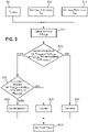
- the figure 2 illustrates the main steps in controlling and regulating heating systems for a room as a whole over a period of time.
- step S1 a set temperature T cons is received.
- the setpoint temperature T cons can be entered by a user, via the user interface for example. This setpoint temperature is to be reached in the room.
- the user enters a time schedule over the period. More specifically, the user fills in at least two time slots and preferably at least three time slots.
- the time slots can be defined on a daily basis, so that each day of the given period is divided according to these time slots. Alternatively, the time slots can be set weekly, so that each week of the given period is sliced according to these time slots, or again monthly. As an indication, the period of time given may extend from a few weeks, to a few months or even a few years.
- the time slots can correspond to a slot of presence, during which the user is present in the room, a slot of absence, during which the user is absent from the room or a reduced slot, for example when the user sleeps.
- the user can associate a setpoint temperature with each of these time slots.
- the set temperatures may differ according to the time slots.
- the SYST system is then able to build a schedule in which each time slot is associated with a setpoint temperature to be respected.
- the picture 2 presents the case where a time range has not been defined, regulation and control are done on the basis of a single setpoint temperature. However, it is understood that the steps described below apply in the same way in the case where a schedule has been constructed.
- the equation above indicates that the indoor temperature changes over time, depending on its value at the previous time step, the state of the heating system (on or off) and the difference between indoor temperatures and exterior.
- T int ( i 0) is equal to the setpoint temperature.
- the interior temperature T int is estimated at each time step ⁇ t .
- the time step can be equal to 15 minutes.
- the forecast of the interior temperature T int in the room is made over the given period.
- the values of the interior temperature T int are for example stored on the server SERV.
- the heating of the room is mainly linked to the difference between the interior temperature T int of the room and the outside temperature T ext , obtained if necessary at a time step equal to that of T int .
- the outside temperature can be obtained by means of meteorological data stored on the server SERV or else by means of a temperature sensor placed outside the premises and connected to the device DISP.
- non-thermal-sensitive uses we mean uses involving electricity consumption that is not sensitive to temperature.
- the electricity consumption of these uses does not depend on the outside and/or inside temperature.
- these uses are, for example, cooking, at least part of the domestic hot water, etc.
- Steps S2 to S6 can be performed on the server SERV.
- step S7 the user can enter an overall maximum energy consumption.
- the method returns at the output one or more set point temperature values T cons '.
- the user can choose the value of the setpoint temperature T cons ' that he wishes to reach in the room.
- the set temperature(s) T cons ' presented to the user in step S8 have been filtered in order to present to the user the values closest to the set temperature T cons initially received at the step S1.
- the determination of the setpoint temperature T cons ' can be carried out locally.
- the DISP device determines this setpoint temperature.
- the construction of the global energy consumption forecasting model is carried out on the server SERV and the determination of a setpoint temperature T cons ' is carried out locally on the device DISP.
- the set point temperature(s) T cons ' retained by the user are sent to the THERM thermostat.
- the DISP device is responsible for controlling and regulating the heating systems SC so that the interior temperature Tint of the room reaches the setpoint temperature T cons '.
- the success of the global energy consumption forecasting model is based on precise and personalized knowledge, depending on the room in particular, of the thermal parameters K 1 , K 2 (called dynamic parameters in the remainder of the description) as well as the heat loss coefficient GV, the interior temperature threshold Threshold and the total energy consumption in non-thermosensitive uses Talon (called static parameters in the remainder of the description).
- the dynamic parameters K 1 , K 2 make it possible to estimate, from a setpoint temperature T cons and an outside temperature T ext , the dynamic evolution of the inside temperature T int .
- the historical data of the room can correspond to the estimates of the interior temperature T int , the setpoint temperature T cons and the change in the exterior temperature T ext over at least part of the time period.
- This historical data can be stored in the server SERV.
- the parameters can be set to default values, which correspond to the behavior of an average building.
- the static parameters make it possible to estimate an overall energy consumption necessary to respect a known setpoint temperature.
- the static parameters include: the level of heat loss from the GV room, the energy consumption of Talon non-thermosensitive uses, expressed in kWh, and the interior temperature (or the difference between interior and exterior temperatures) Threshold below which heating requirements are nil or negligible. The higher the value of GV, the more energy will be needed to maintain the room at a chosen temperature.
- values can be used. These values are for example calculated from thermal simulation software and/or from a questionnaire filled in by the user on the premises.
- the picture 3 is a flowchart illustrating the main steps of a method for determining which values of the static parameters are to be used.
- steps S9 to S11 the historical data of the overall energy consumption, of the indoor temperature T int measured in the room and of the outdoor temperature T ext are obtained. This historical data is obtained for each past day of at least part of the time period.
- step S12 the positive difference Pot degH between the interior temperature T int of the room and the exterior temperature T ext , at each time step for each past day of the time period is calculated in step S12.
- step S13 the number of days where the positive deviation Pot degH is strictly greater than a maximum positive deviation, and where the overall energy consumption is greater than zero is counted. If this number of days is greater than a predefined maximum number of days, the static parameters are calculated according to a first mode, called “winter mode” in step S14.
- step S15 it is determined in step S15 whether a number of days where the positive deviation Pot degH is strictly less than a minimum deviation is greater than a predefined minimum number of days. If so, the static parameters are calculated according to a second mode, called “summer mode” in step S17. If this is not the case, the static parameters are calculated according to an “initialization” mode. At step S18, the values of the static parameters GV, Threshold and Talon are returned.
- the minimum difference is equal to 48° C.h
- the maximum difference is equal to 192° C. h
- the minimum number of days is equal to 5 days
- the maximum number of days is equal to 20 days.
- the figures 4 to 6 are flowcharts illustrating the steps making it possible to calculate the static parameters respectively according to the “initialization”, “summer” and “winter” mode.
- the method uses for example a “user profile”, which makes it possible to determine in broad strokes the characteristics of the room and its energy consumption.
- This profile can be completed by the user by means of a series of questions (for example the year of construction of the dwelling, the surface, the number of occupants, the type of heating system, the type of production system domestic hot water).
- the profile can be more or less detailed, to improve the accuracy of the estimates.
- the customer profile is injected into thermal simulation software.
- the initialized value of Talon is calculated from the annual historical data of the overall energy consumption and of the space heating consumption obtained in step S20. The difference between these two consumptions divided by the number of days in the year (365) makes it possible to obtain the value of Talon in step S21.
- steps S22 and S23 historical data of a weekly heating consumption and an average outdoor temperature for N sub-periods, each lasting one week, are obtained.
- the positive deviation Pot degH is calculated in step S24, taking as the value of the interior temperature 20° C. and a time step equal to 24 h, so that the positive deviation Pot degH is obtained for a representative day of each sub-period N of a week.
- the average daily heating consumption is obtained from the weekly heating consumption in step S25.
- steps S26 and S27 only the values of the weekly heating consumption greater than 0.001 and the values of the positive deviation Pot degH greater than 12 are kept so as not to falsify the results.
- step S29 The values of the static parameters GV, Threshold and Talon of the “initialization” mode are obtained in step S29.
- the values of the static parameters GV, Threshold and Talon of the "initialization" mode are obtained by means of a base of data from thermal simulation or statistical analysis of user data.
- the figure 5 illustrates the calculation of the static parameters in the “summer” mode.
- steps S30 and S31 the historical data of the measured interior temperature T int , of the exterior temperature T ext and of the overall daily consumption are obtained.
- step S32 The difference between the indoor temperature T int and the outdoor temperature T ext is calculated in step S32. Then, in step S33, the calculation of the median C of the overall daily consumption for the days for which the difference between the interior temperature T int and the exterior temperature T ext is less than the minimum difference is performed.
- N is the number of days for which the difference between the indoor temperature T int and the outdoor temperature T ext is less than the minimum difference.
- step S35 the values of the RMSE error and of the median C associated with the minimum deviation are returned.
- Steps S33 to S35 can be repeated for different values of the minimum deviation. For example, with each new calculation, the minimum difference is increased or decreased by a step of 12°C.h, with a minimum difference between 48 and 192°C.h. In this way, a plurality of triplets of values (RMSE, C, minimum deviation) are obtained at step S35.
- RMSE, C minimum deviation
- the static parameter Talon takes the value of the median C of the triplet for which the error RMSE is the smallest.
- the static parameters GV and Threshold take the values of the initialized static parameters, calculated at the figure 4 .
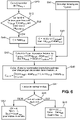
- the figure 6 illustrates calculation of static parameters in “winter” mode.
- step S40 the daily positive deviation Pot degH is calculated according to the historical data of the interior and exterior temperatures.
- step S41 the daily historical data of the global energy consumption C are obtained.
- step S42 it is determined whether the number of days for which the positive deviation Pot degH is less than the maximum deviation is greater than a maximum number of days. If so, the coefficient C takes the value of the median of the overall energy consumption for the days for which the positive deviation Pot degH is less than the maximum deviation, as illustrated in step S43. Otherwise, the coefficient C takes the value of the initialized static parameter Talon (step S44).
- the quadruplet values (minimum deviation, A, C and RMSE) are returned.
- Steps S42 to S47 described above can be repeated for different values of the minimum deviation. For example, at each iteration of these steps the value of the minimum difference increases or decreases by a step of 12°Ch, with the minimum difference between 48°Ch and 192°Ch Thus, a plurality of quadruplets (difference minimum, A, C and RMSE) is returned to step S47.
- the static parameters GV, Heel and Threshold keep the values of the "initialization" mode described with reference to the figure 4 (step S49).
- the static parameters GV, Talon and Threshold may no longer be calculated. For example, provision can be made to calculate these parameters again when the user of the room changes, or even when the energy consumption mode changes, for example.
- the figure 7 illustrates more precisely the estimation of the interior temperature Tint from at least one setpoint temperature.
- the indoor temperature forecast Tint makes it possible to go from a desired setpoint temperature to an indoor temperature respecting this setpoint temperature. If the user has defined a schedule of constraints in which several time slots are respectively associated with a setpoint temperature, the forecast of the interior temperature Tint makes it possible to respect these setpoint temperatures during the associated time slot.
- the setpoint temperature T cons is received. Forecasts of the outdoor temperature T ext over the time period are also received. For example, these forecasts are received from the server SERV which has access to the weather forecasts for the given period. These data are for example received at each time step, for example equal to 15 minutes.
- the values of the dynamic parameters K 1 , K 2 are also received.
- an initial indoor temperature may be received. This value corresponds for example to an interior temperature measured by the thermostat. As a variant, it is possible to take a default interior temperature, for example equal to 20° C. As a variant, it is also possible to take an initial interior temperature equal to the setpoint temperature T cons .
- the estimate includes the successive calculation, at each time step, of a Tint value, which represents the estimate of the interior temperature, and a Heating state value, which represents the state of the heating system (1 if On or 0 if Stop) at each time step.
- the estimation of the value of T int at each time step i is carried out from the data T int and Heating state of the previous time step ( i-1 ), the data of the setpoint temperature T cons and the outdoor temperature T ext at time step i and values of the dynamic parameters K 1 , K 2 .
- step S51 illustrates the initialization of the various parameters useful for estimating the interior temperature Tint.
- Step S53 then includes the estimation of the interior temperature T int at the next time step i+1.
- step S54 it is determined whether the indoor temperature at time step i+1 is lower than the set temperature. If this is the case, the Heating state boolean is forced to 1, otherwise it is forced to 0. As long as the time step is less than the time step illustrating the end of the time period, the steps are repeated by systematically incrementing of 1 the time step.
- step S56 the process is stopped.
- the estimated interior temperature Tint at each time step is returned at the output. With this estimate of the temperature interior over the entire period of time, it is possible to construct the energy consumption model as described with reference to the picture 2 .
- the method according to the invention also makes it possible to control and regulate a room heating system in a room, independently of each other.
- the global energy consumption forecasting model can be applied to each of the rooms in the room, as a function of the setpoint temperature T cons associated with this room.
- a maximum value of the overall energy consumption can be defined, so that from the forecast model, the method makes it possible to return at the output new setpoint temperatures T cons , respectively associated with a room of the room.
- the static parameters GV and Threshold can be recalculated locally, ie for each part.
- the static parameter Talon does not need to be recalculated since it represents the energy consumption of the room for non-thermosensitive uses.
- the Room Threshold parameter of each room is equal to the Threshold parameter calculated for the room.
- the Room Threshold parameter of each room is obtained by linear regression, as described above.
- the Talon parameter is set to zero.
- part GV parameter The calculation of the part GV parameter is described below for a single part. It is understood that this calculation is made for each of the rooms in the room that can be controlled by means of the DISP device.
- the Part ratio parameter is calculated. According to one embodiment, this may be the ratio of the number of heating systems (for example the number of radiators) present in the room by the total number of heating systems in the room.
- it may be the ratio of the area of the room to the total area of the room.
- it may be the ratio of the power of the heating installed in the room relative to the power of the heating installed in the room.
- This parameter is a summary indicator of the heating needs of the room, relative to the whole room.
- the room HS static parameter is calculated as the product of the room HS static parameter and the room Ratio parameter.
- the two alternative embodiments are one or the other implemented depending on certain conditions.
- the figure 8 is a flowchart illustrating the main steps of the control and regulation process room by room, in the case where the room includes controllable rooms and non-controllable rooms.
- non-controllable parts equipped with a heating system that cannot be controlled by means of the DISP device. In order to solve this problem, it is possible to define two fictitious sub-rooms.
- a first sub-room is defined as comprising an identical interior temperature for all the rooms.
- the interior temperature can be calculated as the average of the interior temperatures measured by the thermostat over a sub-period of time, for example equal to one week.
- This first sub-room is the non-controllable room.
- the second sub-room is a controlled room for which the interior temperature of each of the rooms is directly linked to the desired setpoint temperature T cons .
- a room comprises N rooms of which only P rooms can be controlled, with P equal to or less than N.
- the heating consumption for room p For each controllable room p, it is possible to calculate the heating consumption for room p, knowing that it is controlled. In this case, the interior temperature can vary according to the setpoint temperature T cons desired in this room. It is also possible to calculate the heating consumption for room p, assuming that it is not controlled. In this case, the interior temperature is constant and identical for all the rooms. Finally, it is possible to calculate the heating consumption for the whole room, assuming that no room is controlled. This is possible thanks to the static coefficients GV room and Threshold room of each room, as well as to the static coefficients of the room GV and Threshold.
- steps S60, S61 and S62 the parameters GV, Threshold, Talon, Pot degH , GV part , Part threshold and Pot degHPi è ce are received.
- the positive deviation Pot degH of the room is calculated daily, taking as value of the interior temperature T int a single value, chosen from the average of the interior temperatures measured by a sensor in the rooms equipped with such a sensor on a sub- period of time, for example a week, or a default value, for example 20°C, or even the average of the interior temperature measured in a single room over a sub-period of time, for example a week.
- the positive deviation per room Pot degHPi è ce is calculated for each room, from the estimated indoor temperature, based on the setpoint temperature T cons .
- the positive difference Pot degHRoom is calculated by retrieving the setpoint temperature T cons of this room then by estimating the interior temperature corresponding to this setpoint.
Landscapes
- Engineering & Computer Science (AREA)
- Physics & Mathematics (AREA)
- Thermal Sciences (AREA)
- Chemical & Material Sciences (AREA)
- Combustion & Propulsion (AREA)
- Mechanical Engineering (AREA)
- General Engineering & Computer Science (AREA)
- General Physics & Mathematics (AREA)
- Automation & Control Theory (AREA)
- Air Conditioning Control Device (AREA)
- Control Of Temperature (AREA)
Claims (11)
- IT-gesteuertes Verfahren zur Steuerung und Regelung eines Heizungssystems einer Räumlichkeit über einen Zeitraum, ausgehend von einem empfangenen Sollwert einer gewünschten Temperatur, der eine Solltemperatur (Tsoll) definiert, wobei das Verfahren die folgenden Schritte umfasst:- Erstellen eines Modells zur Vorhersage eines Gesamtenergieverbrauchs der Räumlichkeit, der es ermöglicht, eine Innentemperatur (Tint) der Räumlichkeit gleich der Solltemperatur (Tsoll) über den genannten Zeitraum aufrechtzuerhalten, wobei das Modell als Funktion der Solltemperatur (Tsoll) durch eine Gleichung ausgedrückt wird:
 ∘ Cglobal für den prognostizierten Gesamtenergieverbrauch der Räumlichkeit über den Zeitraum steht,∘ GV für einen Koeffizienten für die Wärmeverluste der Räumlichkeit steht,∘ PotdegH für eine positive Abweichung zwischen einer geschätzten Innentemperatur (Tint) der Räumlichkeit und einer Außentemperatur (Text) steht, wobei die geschätzte Innentemperatur (Tint) von der Solltemperatur (Tsoll) abhängt und wobei die positive Abweichung in jedem Zeitschritt über den Zeitraum berechnet wird,∘ Seuil einen Schwellenwert der Innentemperatur (Tint) darstellt, bei dessen Überschreitung ein Heizungssystem der Räumlichkeit in den Deaktivierungszustand versetzt wird, und∘ Talon für den Gesamtenergieverbrauch der Räumlichkeit für nicht wärmeempfindliche Zwecke steht, der aus statistischen Daten erhalten wurde;- dann Bestimmen eines Maximalwertes des Gesamtenergieverbrauchs über den Zeitraum, dadurch gekennzeichnet, dass das Verfahren den folgenden Schritt umfasst:
ausgehend von dem Modell zur Vorhersage des Gesamtenergieverbrauchs der Räumlichkeit:
o am Ausgang Erhalten einer neuen Solltemperatur (Tsoll'), die in der Räumlichkeit erreicht werden soll, so dass der Wert des Gesamtenergieverbrauchs der Räumlichkeit nach Ablauf des Zeitraums kleiner oder gleich dem Maximalwert ist,- wobei das Verfahren einen weiteren Schritt des Sendens der neuen Solltemperatur (Tsoll') an einen Thermostat umfasst, der die Steuerung und Regelung des Heizungssystems ermöglicht,wobei das Modell ferner zur Vorhersage des Energieverbrauchs durch iterative Berechnung der Innentemperatur (Tint) der Räumlichkeit aus den thermischen Parametern (K1, K2) der Räumlichkeit, der Außentemperatur (Text) und der in der vorherigen Iteration berechneten Innentemperatur (Tint) erstellt wird. - Verfahren nach Anspruch 1, wobei eine Konstruktion des Modells einen vorhergehenden Schritt umfasst:- eine Schätzung der Innentemperatur (Tint) der Räumlichkeit, wobei die Schätzung iterativ in jedem Zeitschritt Δt durchgeführt wird, wobei die Schätzung ausgedrückt wird durch:und
 ∘ Tint die geschätzte Innentemperatur (Tint) bei der Iteration i ist,∘ K 1 , K 2 thermische Parameter der Räumlichkeit sind, die für einen Temperaturanstieg bzw. einen Temperaturabfall der Räumlichkeit stehen, wobei K 1 , K 2 aus historischen Daten der Räumlichkeit gewonnen werden,∘ Étatchauffage ein boolescher Ausdruck ist, der für den Zustand der Aktivierung oder Deaktivierung des Heizungssystems steht,∘ Text für die Außentemperatur (Text) der Räumlichkeit steht, die aus vorhergesagten meteorologischen Daten abgeleitet wurde;mit einer ersten Iteration oder einem Wert der Anfangstemperatur T int(i0) der aus einem und/oder dem anderen der folgenden gewählt ist:∘ einer Standardtemperatur,∘ der Solltemperatur (Tsoll),∘ einer gemessenen Temperatur;- eine Bestimmung einer positiven Abweichung zwischen der geschätzten Innentemperatur (Tint) der Räumlichkeit und der Außentemperatur (Text) in jedem Zeitschritt ist gegeben durch:
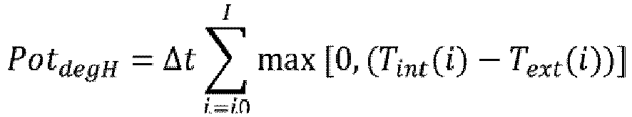 ∘ PotdegH für die positive Abweichung zwischen der geschätzten Innentemperatur (Tint) der Räumlichkeit und der Außentemperatur (Text) über den gesamten Zeitraum steht;∘ Tint (i) und Text (i) jeweils für die geschätzte Innentemperatur (Tint) bzw. die Außentemperatur (Text) in jedem Zeitschritt stehen.
 - Verfahren nach Anspruch 2, wobei in jedem Zeitschritt ein Vergleich zwischen dem geschätzten Wert der Innentemperatur (Tint) und dem Wert der Solltemperatur (Tsoll) durchgeführt wird, und wenn der Wert der geschätzten Temperatur in diesem Zeitschritt größer oder gleich dem Wert der Solltemperatur (Tsoll) ist:- der boolesche Ausdruck Étatchauffage auf null gesetzt wird.
- Verfahren nach einem der Ansprüche 2 oder 3, wobei in jedem Zeitschritt ein Vergleich zwischen dem geschätzten Wert der Innentemperatur (Tint) und dem Wert der Solltemperatur (Tsoll) durchgeführt wird und, wenn der geschätzte Wert der Temperatur in diesem Zeitschritt kleiner als der Wert der Solltemperatur (Tsoll) ist:- der boolesche Ausdruck Étatchauffage auf 1 gesetzt wird.
- Verfahren nach einem der Ansprüche 2 bis 4, wobei das Verfahren einen Schritt der Initialisierung der Werte des Wärmeverlustkoeffizienten GV, des Innentemperaturschwellenwerts (Tint) Seuil und des Gesamtenergieverbrauchs für nicht wärmeempfindliche Zwecke Talon mittels einer thermischen Simulation der Räumlichkeit umfasst, die es ermöglicht, geschätzte Energieverbrauchsdaten zu erzeugen, wobei die initialisierten Werte der Parameter GV, Seuil und Talon in das Vorhersagemodell eingespeist werden.
- Verfahren nach Anspruch 4, dadurch gekennzeichnet, dass während des Zeitraums die Werte des Wärmeverlustkoeffizienten GV, des Schwellenwertes der Innentemperatur (Tint) Seuil und des Gesamtenergieverbrauchs für nicht wärmeempfindliche Zwecke Talon neu berechnet werden, wobei die Neuberechnung Folgendes umfasst:- Erhalten von historischen Daten der gemessenen Innentemperatur (Tint), der Außentemperatur (Text) und des Gesamtverbrauchs an Heizenergie,- Berechnen der positiven Abweichung PotdegH zwischen der gemessenen Innentemperatur (Tint) der Räumlichkeit und der Außentemperatur (Text) in jedem Zeitschritt für jeden vergangenen Tag des Zeitraums, und- wenn eine Anzahl von vergangenen Tagen, an denen die positive Abweichung PotdegH größer als eine maximale Abweichung ist und an denen der Gesamtenergieverbrauch größer als 0 ist, der Wärmeverlustkoeffizient GV, der Schwellenwert der Innentemperatur (Tint) Seuil und der Gesamtenergieverbrauch für nicht wärmeempfindliche Zwecke Talon nach einem ersten Modus berechnet werden, oder- wenn eine Anzahl von vergangenen Tagen, an denen die positive Abweichung PotdegH kleiner als eine minimale Abweichung ist, größer ist als eine minimale Anzahl von Tagen, der Wärmeverlustkoeffizient GV, der Schwellenwert der Innentemperatur (Tint) Seuil und der Gesamtenergieverbrauch für nicht wärmeempfindliche Zwecke Talon nach einem zweiten Modus berechnet werden,- andernfalls behalten der Wärmeverlustkoeffizient GV, der Schwellenwert der Innentemperatur (Tint) Seuil und der Gesamtenergieverbrauch für nicht wärmeempfindliche Zwecke Talon ihre jeweiligen Werte bei, die im Initialisierungsschritt ermittelt wurden.
- Verfahren nach einem der Ansprüche 1 bis 6, dadurch gekennzeichnet, dass es umfasst:- Festlegen mehrerer Solltemperaturen, die jeweils einem Raum der Räumlichkeit aus einer Vielzahl von Räumen zugeordnet sind;- Anwenden des Modells zur Vorhersage des Gesamtenergieverbrauchs auf die Räume der Räumlichkeit, so dass die Innentemperatur (Tint) jedes Raumes die dem Raum zugeordnete Solltemperatur (Tsoll) erreicht;- dann Festlegen eines Maximalwertes für den Gesamtenergieverbrauch über den Zeitraum und anhand des Vorhersagemodells des Gesamtenergieverbrauchs der Räumlichkeit:- am Ausgang Erhalten neuer Solltemperaturen, die in den Räumen der Räumlichkeit erreicht werden sollen, die jeweils den Solltemperaturen zugeordnet sind, so dass der Wert des Gesamtenergieverbrauchs der Räumlichkeit kleiner oder gleich dem Maximalwert über den Zeitraum ist.
- Verfahren nach Anspruch 6 in Kombination mit Anspruch 7, wobei die Werte des Schwellenwertes der Innentemperatur (Tint) Seuil und des Gesamtenergieverbrauchs für nicht wärmeempfindliche Zwecke Talon ihre jeweiligen für die Räumlichkeit bestimmten Werte beibehalten, wobei das Verfahren ferner während des Zeitraums eine Berechnung eines Wärmeverlustkoeffizienten GVpièce für jeden der Räume der Räumlichkeit umfasst, wobei die Berechnung Folgendes umfasst:- Erhalten von historischen Daten der Außentemperatur (Text);und, für jeden Raum der Räumlichkeit:- Erhalten von historischen Daten der gemessenen Innentemperatur (Tint) und des Heizenergieverbrauchs des betreffenden Raums der Räumlichkeit;- Berechnen einer positive Abweichung PotdegHPièce zwischen der gemessenen Innentemperatur (Tint) des Raums und der Außentemperatur (Text) in jedem Zeitschritt für jeden vergangenen Tag des Zeitraums, und- wenn eine Anzahl von vergangenen Tagen, an denen die positive Abweichung PotdegHPièce größer als eine maximale Abweichung ist und an denen der Gesamtheizenergieverbrauch größer als 0 ist, größer als eine maximale Anzahl von Tagen ist, der Wärmeverlustkoeffizient des Raums GVpièce durch lineare Regression der folgenden Gleichung berechnet wird:
 - andernfalls wird der Wärmeverlustkoeffizient GVpièce mit Hilfe der folgenden Gleichung berechnet:wobei Ratiopièce aus einem und/oder dem anderen gewählt wird:
 - das Verhältnis einer Anzahl von Heizkörpern in dem genannten Raum der Räumlichkeit zu der Gesamtzahl von Heizkörpern der Räumlichkeit;- das Verhältnis einer in dem Raum installierten Heizleistung zu einer Gesamtheizleistung der Wohnung;- das Verhältnis der Fläche des Raumes zur Gesamtfläche der Wohnung.
 - Verfahren nach einem der Ansprüche 1 bis 8, wobei wenigstens zwei Solltemperaturen und vorzugsweise wenigstens drei Solltemperaturen festgelegt werden, wobei jede Solltemperatur (Tsoll) einem wiederkehrenden Zeitbereich eines Tages des Zeitraums zugeordnet ist und die Schritte zur Regelung des Verfahrens für jede der Solltemperaturen in Abhängigkeit von dem Zeitbereich, in dem die Schritte des Verfahrens ausgeführt werden, durchgeführt werden.
- Computerprogramm, dadurch gekennzeichnet, dass es Anweisungen zur Durchführung des Verfahrens nach einem der vorhergehenden Ansprüche enthält, wenn dieses Programm von einem Prozessor ausgeführt wird.
- Computersystem zur Steuerung und Regelung eines Systems zur Beheizung einer Räumlichkeit über einen Zeitraum, ausgehend von einem Sollwert der gewünschten Temperatur, der eine Solltemperatur (Tsoll) definiert, mit einer Computerverarbeitungsschaltung (DISP) zur Durchführung des Verfahrens nach einem der Ansprüche 1 bis 9.
Applications Claiming Priority (2)
| Application Number | Priority Date | Filing Date | Title |
|---|---|---|---|
| FR1858027A FR3085767B1 (fr) | 2018-09-06 | 2018-09-06 | Procede et systeme de pilotage et de regulation d'un systeme de chauffage d'un local |
| PCT/EP2019/072182 WO2020048761A1 (fr) | 2018-09-06 | 2019-08-19 | Procédé et système de pilotage et de régulation d'un système de chauffage d'un local |
Publications (2)
| Publication Number | Publication Date |
|---|---|
| EP3847520A1 EP3847520A1 (de) | 2021-07-14 |
| EP3847520B1 true EP3847520B1 (de) | 2022-06-15 |
Family
ID=63834286
Family Applications (1)
| Application Number | Title | Priority Date | Filing Date |
|---|---|---|---|
| EP19753128.8A Active EP3847520B1 (de) | 2018-09-06 | 2019-08-19 | Verfahren und system zur steuerung und regelung eines heizsystems für gebäude |
Country Status (4)
| Country | Link |
|---|---|
| EP (1) | EP3847520B1 (de) |
| ES (1) | ES2925259T3 (de) |
| FR (1) | FR3085767B1 (de) |
| WO (1) | WO2020048761A1 (de) |
Families Citing this family (2)
| Publication number | Priority date | Publication date | Assignee | Title |
|---|---|---|---|---|
| FI4227754T3 (fi) * | 2022-02-15 | 2024-04-24 | Siemens Schweiz Ag | Jäähdytys- tai lämmitystehon arviot |
| CN115254666B (zh) * | 2022-07-21 | 2024-07-16 | 安徽瑞联节能科技股份有限公司 | 一种岩棉板生产用在线检测系统 |
Family Cites Families (4)
| Publication number | Priority date | Publication date | Assignee | Title |
|---|---|---|---|---|
| FR2964727B1 (fr) * | 2010-09-14 | 2012-10-12 | Commissariat Energie Atomique | Systeme thermique a faible puissance pour l'habitat |
| US9298197B2 (en) * | 2013-04-19 | 2016-03-29 | Google Inc. | Automated adjustment of an HVAC schedule for resource conservation |
| FR3031598A1 (fr) | 2015-01-13 | 2016-07-15 | Ecometering | Dispositif thermique ameliore |
| CN109416550B (zh) * | 2016-05-04 | 2021-09-10 | 江森自控科技公司 | 用户控制装置和多功能家庭控制系统 |
-
2018
- 2018-09-06 FR FR1858027A patent/FR3085767B1/fr active Active
-
2019
- 2019-08-19 EP EP19753128.8A patent/EP3847520B1/de active Active
- 2019-08-19 ES ES19753128T patent/ES2925259T3/es active Active
- 2019-08-19 WO PCT/EP2019/072182 patent/WO2020048761A1/fr unknown
Also Published As
| Publication number | Publication date |
|---|---|
| EP3847520A1 (de) | 2021-07-14 |
| ES2925259T3 (es) | 2022-10-14 |
| WO2020048761A1 (fr) | 2020-03-12 |
| FR3085767B1 (fr) | 2020-11-20 |
| FR3085767A1 (fr) | 2020-03-13 |
Similar Documents
| Publication | Publication Date | Title |
|---|---|---|
| EP2707781B1 (de) | Verfahren zur vorhersage des energieverbrauchs eines gebäudes | |
| US12188667B1 (en) | Thermal modeling technology | |
| US11859838B2 (en) | System and method for aligning HVAC consumption with renewable power production with the aid of a digital computer | |
| Lomet et al. | Statistical modeling for real domestic hot water consumption forecasting | |
| EP2460057B1 (de) | Energieverwaltung in einem gebäude | |
| WO2015086994A1 (fr) | Prediction d'une consommation de fluide effacee | |
| EP3847520B1 (de) | Verfahren und system zur steuerung und regelung eines heizsystems für gebäude | |
| US20230228446A1 (en) | Scalable control of heat pumps with limited smart-home devices | |
| FR3072514A1 (fr) | Systeme de controle et de pilotage d’equipements energetiques distribues. | |
| Ruan et al. | Estimating demand flexibility using Siamese LSTM neural networks | |
| WO2018060157A1 (fr) | Procédé d'auto-paramétrage auto-adaptatif d'un système de chauffage et de production d'eau chaude sanitaire | |
| WO2024114018A1 (zh) | 风力发电机组的发电性能评估方法和装置 | |
| EP2976612B1 (de) | Verfahren zur herstellung einer wärmediagnose eines gebäudes oder eines gebäudeteils | |
| FR3135798A1 (fr) | Procédé de prévision d’une puissance produite par au moins un panneau photovoltaïque | |
| EP3291033A1 (de) | System und verfahren zum abschätzen des thermischen verhaltens eines gebäudes zur optimalen heizungssteuerung | |
| WO2015092193A1 (fr) | Fourniture d'energie optimisee d'un reseau de distribution. | |
| EP4198674A1 (de) | Verfahren zur auswahl eines ansteuermodus für passive thermische regelungsvorrichtungen eines gebäudes | |
| FR2979451A1 (fr) | Procede de determination de la part de la consommation electrique liee aux temperatures exterieures | |
| EP3460534B1 (de) | Verfahren und vorrichtung zur indirekten bestimmung eines einfallenden solarstroms | |
| KR102536500B1 (ko) | 특수일의 전력수요예측 장치 및 방법 | |
| JP7607548B2 (ja) | 学習装置、電力需要推論装置、系統制御システム、需給制御システム、設備形成支援システムおよびプログラム | |
| FR3031598A1 (fr) | Dispositif thermique ameliore | |
| FR3141544A1 (fr) | Procédé d’estimation d’un indicateur collectif de réduction de consommation énergétique pour un ensemble de dispositifs thermiques, dispositif électronique d’estimation et produit programme d’ordinateur associés | |
| Parts et al. | Wax actuator’s empirical model development and application to underfloor heating control with varying complexity of controller modelling detail | |
| FR3102543A1 (fr) | Procédé et système de pilotage d’un système thermique d’un bâtiment |
Legal Events
| Date | Code | Title | Description |
|---|---|---|---|
| STAA | Information on the status of an ep patent application or granted ep patent |
Free format text: STATUS: UNKNOWN |
|
| STAA | Information on the status of an ep patent application or granted ep patent |
Free format text: STATUS: THE INTERNATIONAL PUBLICATION HAS BEEN MADE |
|
| PUAI | Public reference made under article 153(3) epc to a published international application that has entered the european phase |
Free format text: ORIGINAL CODE: 0009012 |
|
| STAA | Information on the status of an ep patent application or granted ep patent |
Free format text: STATUS: REQUEST FOR EXAMINATION WAS MADE |
|
| 17P | Request for examination filed |
Effective date: 20210206 |
|
| AK | Designated contracting states |
Kind code of ref document: A1 Designated state(s): AL AT BE BG CH CY CZ DE DK EE ES FI FR GB GR HR HU IE IS IT LI LT LU LV MC MK MT NL NO PL PT RO RS SE SI SK SM TR |
|
| DAV | Request for validation of the european patent (deleted) | ||
| DAX | Request for extension of the european patent (deleted) | ||
| GRAP | Despatch of communication of intention to grant a patent |
Free format text: ORIGINAL CODE: EPIDOSNIGR1 |
|
| STAA | Information on the status of an ep patent application or granted ep patent |
Free format text: STATUS: GRANT OF PATENT IS INTENDED |
|
| INTG | Intention to grant announced |
Effective date: 20220209 |
|
| GRAS | Grant fee paid |
Free format text: ORIGINAL CODE: EPIDOSNIGR3 |
|
| GRAA | (expected) grant |
Free format text: ORIGINAL CODE: 0009210 |
|
| STAA | Information on the status of an ep patent application or granted ep patent |
Free format text: STATUS: THE PATENT HAS BEEN GRANTED |
|
| AK | Designated contracting states |
Kind code of ref document: B1 Designated state(s): AL AT BE BG CH CY CZ DE DK EE ES FI FR GB GR HR HU IE IS IT LI LT LU LV MC MK MT NL NO PL PT RO RS SE SI SK SM TR |
|
| REG | Reference to a national code |
Ref country code: CH Ref legal event code: EP Ref country code: GB Ref legal event code: FG4D Free format text: NOT ENGLISH |
|
| REG | Reference to a national code |
Ref country code: IE Ref legal event code: FG4D Free format text: LANGUAGE OF EP DOCUMENT: FRENCH |
|
| REG | Reference to a national code |
Ref country code: DE Ref legal event code: R096 Ref document number: 602019015966 Country of ref document: DE |
|
| REG | Reference to a national code |
Ref country code: AT Ref legal event code: REF Ref document number: 1498762 Country of ref document: AT Kind code of ref document: T Effective date: 20220715 |
|
| REG | Reference to a national code |
Ref country code: LT Ref legal event code: MG9D |
|
| REG | Reference to a national code |
Ref country code: ES Ref legal event code: FG2A Ref document number: 2925259 Country of ref document: ES Kind code of ref document: T3 Effective date: 20221014 |
|
| REG | Reference to a national code |
Ref country code: NL Ref legal event code: MP Effective date: 20220615 |
|
| PG25 | Lapsed in a contracting state [announced via postgrant information from national office to epo] |
Ref country code: SE Free format text: LAPSE BECAUSE OF FAILURE TO SUBMIT A TRANSLATION OF THE DESCRIPTION OR TO PAY THE FEE WITHIN THE PRESCRIBED TIME-LIMIT Effective date: 20220615 Ref country code: NO Free format text: LAPSE BECAUSE OF FAILURE TO SUBMIT A TRANSLATION OF THE DESCRIPTION OR TO PAY THE FEE WITHIN THE PRESCRIBED TIME-LIMIT Effective date: 20220915 Ref country code: LT Free format text: LAPSE BECAUSE OF FAILURE TO SUBMIT A TRANSLATION OF THE DESCRIPTION OR TO PAY THE FEE WITHIN THE PRESCRIBED TIME-LIMIT Effective date: 20220615 Ref country code: HR Free format text: LAPSE BECAUSE OF FAILURE TO SUBMIT A TRANSLATION OF THE DESCRIPTION OR TO PAY THE FEE WITHIN THE PRESCRIBED TIME-LIMIT Effective date: 20220615 Ref country code: GR Free format text: LAPSE BECAUSE OF FAILURE TO SUBMIT A TRANSLATION OF THE DESCRIPTION OR TO PAY THE FEE WITHIN THE PRESCRIBED TIME-LIMIT Effective date: 20220916 Ref country code: FI Free format text: LAPSE BECAUSE OF FAILURE TO SUBMIT A TRANSLATION OF THE DESCRIPTION OR TO PAY THE FEE WITHIN THE PRESCRIBED TIME-LIMIT Effective date: 20220615 Ref country code: BG Free format text: LAPSE BECAUSE OF FAILURE TO SUBMIT A TRANSLATION OF THE DESCRIPTION OR TO PAY THE FEE WITHIN THE PRESCRIBED TIME-LIMIT Effective date: 20220915 |
|
| REG | Reference to a national code |
Ref country code: AT Ref legal event code: MK05 Ref document number: 1498762 Country of ref document: AT Kind code of ref document: T Effective date: 20220615 |
|
| PG25 | Lapsed in a contracting state [announced via postgrant information from national office to epo] |
Ref country code: RS Free format text: LAPSE BECAUSE OF FAILURE TO SUBMIT A TRANSLATION OF THE DESCRIPTION OR TO PAY THE FEE WITHIN THE PRESCRIBED TIME-LIMIT Effective date: 20220615 Ref country code: LV Free format text: LAPSE BECAUSE OF FAILURE TO SUBMIT A TRANSLATION OF THE DESCRIPTION OR TO PAY THE FEE WITHIN THE PRESCRIBED TIME-LIMIT Effective date: 20220615 |
|
| PG25 | Lapsed in a contracting state [announced via postgrant information from national office to epo] |
Ref country code: NL Free format text: LAPSE BECAUSE OF FAILURE TO SUBMIT A TRANSLATION OF THE DESCRIPTION OR TO PAY THE FEE WITHIN THE PRESCRIBED TIME-LIMIT Effective date: 20220615 |
|
| PG25 | Lapsed in a contracting state [announced via postgrant information from national office to epo] |
Ref country code: SM Free format text: LAPSE BECAUSE OF FAILURE TO SUBMIT A TRANSLATION OF THE DESCRIPTION OR TO PAY THE FEE WITHIN THE PRESCRIBED TIME-LIMIT Effective date: 20220615 Ref country code: SK Free format text: LAPSE BECAUSE OF FAILURE TO SUBMIT A TRANSLATION OF THE DESCRIPTION OR TO PAY THE FEE WITHIN THE PRESCRIBED TIME-LIMIT Effective date: 20220615 Ref country code: RO Free format text: LAPSE BECAUSE OF FAILURE TO SUBMIT A TRANSLATION OF THE DESCRIPTION OR TO PAY THE FEE WITHIN THE PRESCRIBED TIME-LIMIT Effective date: 20220615 Ref country code: PT Free format text: LAPSE BECAUSE OF FAILURE TO SUBMIT A TRANSLATION OF THE DESCRIPTION OR TO PAY THE FEE WITHIN THE PRESCRIBED TIME-LIMIT Effective date: 20221017 Ref country code: EE Free format text: LAPSE BECAUSE OF FAILURE TO SUBMIT A TRANSLATION OF THE DESCRIPTION OR TO PAY THE FEE WITHIN THE PRESCRIBED TIME-LIMIT Effective date: 20220615 Ref country code: CZ Free format text: LAPSE BECAUSE OF FAILURE TO SUBMIT A TRANSLATION OF THE DESCRIPTION OR TO PAY THE FEE WITHIN THE PRESCRIBED TIME-LIMIT Effective date: 20220615 Ref country code: AT Free format text: LAPSE BECAUSE OF FAILURE TO SUBMIT A TRANSLATION OF THE DESCRIPTION OR TO PAY THE FEE WITHIN THE PRESCRIBED TIME-LIMIT Effective date: 20220615 |
|
| PG25 | Lapsed in a contracting state [announced via postgrant information from national office to epo] |
Ref country code: PL Free format text: LAPSE BECAUSE OF FAILURE TO SUBMIT A TRANSLATION OF THE DESCRIPTION OR TO PAY THE FEE WITHIN THE PRESCRIBED TIME-LIMIT Effective date: 20220615 Ref country code: IS Free format text: LAPSE BECAUSE OF FAILURE TO SUBMIT A TRANSLATION OF THE DESCRIPTION OR TO PAY THE FEE WITHIN THE PRESCRIBED TIME-LIMIT Effective date: 20221015 |
|
| REG | Reference to a national code |
Ref country code: DE Ref legal event code: R119 Ref document number: 602019015966 Country of ref document: DE |
|
| PG25 | Lapsed in a contracting state [announced via postgrant information from national office to epo] |
Ref country code: MC Free format text: LAPSE BECAUSE OF FAILURE TO SUBMIT A TRANSLATION OF THE DESCRIPTION OR TO PAY THE FEE WITHIN THE PRESCRIBED TIME-LIMIT Effective date: 20220615 Ref country code: AL Free format text: LAPSE BECAUSE OF FAILURE TO SUBMIT A TRANSLATION OF THE DESCRIPTION OR TO PAY THE FEE WITHIN THE PRESCRIBED TIME-LIMIT Effective date: 20220615 |
|
| REG | Reference to a national code |
Ref country code: CH Ref legal event code: PL |
|
| PLBE | No opposition filed within time limit |
Free format text: ORIGINAL CODE: 0009261 |
|
| STAA | Information on the status of an ep patent application or granted ep patent |
Free format text: STATUS: NO OPPOSITION FILED WITHIN TIME LIMIT |
|
| PG25 | Lapsed in a contracting state [announced via postgrant information from national office to epo] |
Ref country code: LU Free format text: LAPSE BECAUSE OF NON-PAYMENT OF DUE FEES Effective date: 20220819 Ref country code: LI Free format text: LAPSE BECAUSE OF NON-PAYMENT OF DUE FEES Effective date: 20220831 Ref country code: DK Free format text: LAPSE BECAUSE OF FAILURE TO SUBMIT A TRANSLATION OF THE DESCRIPTION OR TO PAY THE FEE WITHIN THE PRESCRIBED TIME-LIMIT Effective date: 20220615 Ref country code: CH Free format text: LAPSE BECAUSE OF NON-PAYMENT OF DUE FEES Effective date: 20220831 |
|
| 26N | No opposition filed |
Effective date: 20230316 |
|
| PG25 | Lapsed in a contracting state [announced via postgrant information from national office to epo] |
Ref country code: SI Free format text: LAPSE BECAUSE OF FAILURE TO SUBMIT A TRANSLATION OF THE DESCRIPTION OR TO PAY THE FEE WITHIN THE PRESCRIBED TIME-LIMIT Effective date: 20220615 |
|
| PG25 | Lapsed in a contracting state [announced via postgrant information from national office to epo] |
Ref country code: IE Free format text: LAPSE BECAUSE OF NON-PAYMENT OF DUE FEES Effective date: 20220819 Ref country code: DE Free format text: LAPSE BECAUSE OF NON-PAYMENT OF DUE FEES Effective date: 20230301 |
|
| P01 | Opt-out of the competence of the unified patent court (upc) registered |
Effective date: 20231024 |
|
| PG25 | Lapsed in a contracting state [announced via postgrant information from national office to epo] |
Ref country code: CY Free format text: LAPSE BECAUSE OF FAILURE TO SUBMIT A TRANSLATION OF THE DESCRIPTION OR TO PAY THE FEE WITHIN THE PRESCRIBED TIME-LIMIT Effective date: 20220615 |
|
| PG25 | Lapsed in a contracting state [announced via postgrant information from national office to epo] |
Ref country code: MK Free format text: LAPSE BECAUSE OF FAILURE TO SUBMIT A TRANSLATION OF THE DESCRIPTION OR TO PAY THE FEE WITHIN THE PRESCRIBED TIME-LIMIT Effective date: 20220615 Ref country code: HU Free format text: LAPSE BECAUSE OF FAILURE TO SUBMIT A TRANSLATION OF THE DESCRIPTION OR TO PAY THE FEE WITHIN THE PRESCRIBED TIME-LIMIT; INVALID AB INITIO Effective date: 20190819 |
|
| PG25 | Lapsed in a contracting state [announced via postgrant information from national office to epo] |
Ref country code: MT Free format text: LAPSE BECAUSE OF FAILURE TO SUBMIT A TRANSLATION OF THE DESCRIPTION OR TO PAY THE FEE WITHIN THE PRESCRIBED TIME-LIMIT Effective date: 20220615 |
|
| PGFP | Annual fee paid to national office [announced via postgrant information from national office to epo] |
Ref country code: GB Payment date: 20240823 Year of fee payment: 6 |
|
| PGFP | Annual fee paid to national office [announced via postgrant information from national office to epo] |
Ref country code: BE Payment date: 20240823 Year of fee payment: 6 |
|
| PGFP | Annual fee paid to national office [announced via postgrant information from national office to epo] |
Ref country code: FR Payment date: 20240722 Year of fee payment: 6 |
|
| PGFP | Annual fee paid to national office [announced via postgrant information from national office to epo] |
Ref country code: ES Payment date: 20240909 Year of fee payment: 6 |
|
| PGFP | Annual fee paid to national office [announced via postgrant information from national office to epo] |
Ref country code: IT Payment date: 20240808 Year of fee payment: 6 |
|
| PG25 | Lapsed in a contracting state [announced via postgrant information from national office to epo] |
Ref country code: BG Free format text: LAPSE BECAUSE OF FAILURE TO SUBMIT A TRANSLATION OF THE DESCRIPTION OR TO PAY THE FEE WITHIN THE PRESCRIBED TIME-LIMIT Effective date: 20220615 |
|
| PG25 | Lapsed in a contracting state [announced via postgrant information from national office to epo] |
Ref country code: BG Free format text: LAPSE BECAUSE OF FAILURE TO SUBMIT A TRANSLATION OF THE DESCRIPTION OR TO PAY THE FEE WITHIN THE PRESCRIBED TIME-LIMIT Effective date: 20220615 |