EP3847423B1 - Ultraschallwasserzähler aus mehreren materialien - Google Patents
Ultraschallwasserzähler aus mehreren materialien Download PDFInfo
- Publication number
- EP3847423B1 EP3847423B1 EP18889063.6A EP18889063A EP3847423B1 EP 3847423 B1 EP3847423 B1 EP 3847423B1 EP 18889063 A EP18889063 A EP 18889063A EP 3847423 B1 EP3847423 B1 EP 3847423B1
- Authority
- EP
- European Patent Office
- Prior art keywords
- outer pipe
- ultrasonic
- inner sleeve
- pipe body
- tubular body
- Prior art date
- Legal status (The legal status is an assumption and is not a legal conclusion. Google has not performed a legal analysis and makes no representation as to the accuracy of the status listed.)
- Active
Links
Images




Classifications
-
- G—PHYSICS
- G01—MEASURING; TESTING
- G01F—MEASURING VOLUME, VOLUME FLOW, MASS FLOW OR LIQUID LEVEL; METERING BY VOLUME
- G01F1/00—Measuring the volume flow or mass flow of fluid or fluent solid material wherein the fluid passes through a meter in a continuous flow
- G01F1/66—Measuring the volume flow or mass flow of fluid or fluent solid material wherein the fluid passes through a meter in a continuous flow by measuring frequency, phase shift or propagation time of electromagnetic or other waves, e.g. using ultrasonic flowmeters
- G01F1/667—Arrangements of transducers for ultrasonic flowmeters; Circuits for operating ultrasonic flowmeters
-
- G—PHYSICS
- G01—MEASURING; TESTING
- G01F—MEASURING VOLUME, VOLUME FLOW, MASS FLOW OR LIQUID LEVEL; METERING BY VOLUME
- G01F1/00—Measuring the volume flow or mass flow of fluid or fluent solid material wherein the fluid passes through a meter in a continuous flow
- G01F1/66—Measuring the volume flow or mass flow of fluid or fluent solid material wherein the fluid passes through a meter in a continuous flow by measuring frequency, phase shift or propagation time of electromagnetic or other waves, e.g. using ultrasonic flowmeters
- G01F1/662—Constructional details
-
- G—PHYSICS
- G01—MEASURING; TESTING
- G01F—MEASURING VOLUME, VOLUME FLOW, MASS FLOW OR LIQUID LEVEL; METERING BY VOLUME
- G01F15/00—Details of, or accessories for, apparatus of groups G01F1/00 - G01F13/00 insofar as such details or appliances are not adapted to particular types of such apparatus
- G01F15/006—Details of, or accessories for, apparatus of groups G01F1/00 - G01F13/00 insofar as such details or appliances are not adapted to particular types of such apparatus characterised by the use of a particular material, e.g. anti-corrosive material
Definitions
- the present disclosure relates, in general, to a water meter and, in particular, to an ultrasonic water meter used to determine a flow rate of a fluid moving through a piping arrangement.
- a flow meter such as a water meter, is a device used to measure the volume or flow rate of a fluid being moved through a piping arrangement.
- Water meters are typically used to measure the volume of water consumed by residential and commercial buildings that are supplied with water by a public water supply system. Water meters may also be used at the water source or at various locations throughout the water system in order to determine the flows and flow rates delivered through that portion of the system.
- One type of a water meter is an ultrasonic water meter that uses an ultrasonic transducer to send ultrasonic sound waves through the fluid to determine the fluid's velocity and translate the velocity into a measurement of the fluid volume.
- United States Patent No. 9,714,855 discloses an ultrasonic water meter in which the ultrasonic sound wave is directed through a measurement section in a Z-shaped travel path and in which the measurement section has a reduced width but the same cross-sectional area as the ends of the meter.
- DE 199 44 411 A1 discloses another ultrasonic flow meter with a Z-shaped acoustic path and in which the measurement section has a reduced cross-section through the use of an inner sleeve holding two reflectors.
- an ultrasonic water meter includes a metallic, stainless steel, brass, or bronze outer pipe body having an over-molded inner portion that defines the flow passage and measurement section of the meter or in which a separate inner sleeve made from a polymeric material is inserted and longitudinally secured.
- the metallic outer pipe body is provided to improve body strength and/or in accordance with operational requirements of the customer or due to code requirements of the local jurisdiction. This arrangement provides a metallic-type ultrasonic water meter for those customers that request it. It also enables all of the acoustic parts to fit within the inner polymer body, whether the inner polymer body is an inner sleeve inserted into the outer metallic pipe body or is over molded onto an interior surface of the outer metallic pipe body.
- an ultrasonic water meter includes a metallic body and a polymer inner liner.
- the polymer inner liner may be an insert or may be over molded onto the metallic body.
- the metallic body provides strength and allows the meter to be used in installations where a metallic body is required.
- the polymer inner liner provides acoustic properties similar to those of a plastic ultrasonic meter, minimizing the negative effects of metal on acoustic readings taken in the water passageway. In the example having an over-molded inner liner, the water passageway is completely isolated from the metallic body.
- an ultrasonic flow meter device includes a piping arrangement including a tubular body extending along a longitudinal axis from a first end to a second end and including a measurement section disposed intermediate the first end and the second end, the tubular body defining a fluid passage extending along the longitudinal axis through the tubular body from the first end to the second end; at least two ultrasonic transducers disposed on opposing sides of the tubular body and spaced apart along the longitudinal axis; and at least two reflective elements disposed on the opposing sides of the tubular body and spaced apart along the longitudinal axis.
- the piping arrangement includes an outer pipe body made from a metallic material; and an inner sleeve made from a polymeric material, the inner sleeve being disposed within the outer pipe body.
- the inner sleeve is over molded within the outer pipe body.
- the inner sleeve defines the measurement section and the fluid passage of the piping arrangement.
- Each of the at least two reflective elements is disposed on a respective bracket inserted in the fluid passage.
- the outer pipe body may include a narrowed portion that defines the measurement section in the over-molded inner sleeve.
- the metallic material may be stainless steel, brass, or bronze.
- a method of manufacturing an ultrasonic flow meter device includes providing an outer pipe body made from a metallic material, the outer pipe body having a hollow interior defining an interior surface; injection molding an inner sleeve made from a polymeric material onto the interior surface of the outer pipe body, wherein the outer pipe body and the inner sleeve form a piping arrangement including a tubular body extending along a longitudinal axis from a first end to a second end and including a measurement section disposed intermediate the first end and the second end, the tubular body defining a fluid passage extending along the longitudinal axis through the tubular body from the first end to the second end; assembling at least two ultrasonic transducers on opposing sides of the tubular body and spaced apart along the longitudinal axis; assembling at least two reflective elements on the opposing sides of the tubular body and spaced apart along the longitudinal axis, and wherein each of the at least two reflective elements is disposed on a respective bracket inserted in the fluid passage
- the inner sleeve is injection molded onto the interior surface of the outer pipe body so as to form a sealed engagement between the inner sleeve and the outer pipe body.
- the metallic material may include stainless steel, brass, or bronze.
- an ultrasonic flow meter device includes a piping arrangement including a tubular body extending along a longitudinal axis from a first end to a second end and including a measurement section disposed intermediate the first end and the second end, the tubular body defining a fluid passage extending along the longitudinal axis through the tubular body from the first end to the second end; at least two ultrasonic transducers disposed on opposing sides of the tubular body and spaced apart along the longitudinal axis; and at least two reflective elements disposed on the opposing sides of the tubular body and spaced apart along the longitudinal axis.
- the piping arrangement includes an outer pipe body made from a metallic material; an inner sleeve made from a polymeric material, the inner sleeve being disposed within the outer pipe body; and a fastener configured to secure the inner sleeve within the outer pipe body.
- the inner sleeve defines the measurement section and the fluid passage of the piping arrangement.
- the outer pipe body and the inner sleeve include corresponding apertures that define seats for the at least two ultrasonic transducers and that place the ultrasonic transducers in communication with the measurement section.
- the outer pipe body includes an aperture and the inner sleeve includes a corresponding recess configured to receive the fastener.
- the metallic material may be stainless steel, brass, or bronze.
- the device may further include a sealing gasket disposed between the outer pipe body and the inner sleeve.
- the sealing gasket is configured to seal an engagement between an inner surface of the outer pipe body and an exterior surface of the inner sleeve.
- an ultrasonic flow meter device 100 is shown in accordance with an example not part of the claimed invention.
- the ultrasonic flow meter device 100 may be utilized for a variety of purposes, including for determining a flow rate and/or volume of a liquid, such as water, passing through the ultrasonic flow meter 100 in a piping system.
- the device 100 includes a piping arrangement 101 having a tubular body 102 extending along a longitudinal axis L from a first end 103 to a second end 104.
- the tubular body 102 includes a measurement section 105 disposed within the tubular body 102 intermediate of the first end 103 and the second end 104.
- the tubular body 102 defines a fluid passage 108 extending along the longitudinal axis 1.
- the device 100 also includes two ultrasonic transducers 120a, 120b, which are spaced apart along the longitudinal axis L, disposed on opposing sides 111, 112 of the tubular body 102.
- the device 100 further includes two reflective elements 130a, 130b, which are spaced apart along the longitudinal axis L, disposed on the opposing sides 111, 112 of the tubular body 102.
- the piping arrangement 101 may include a base 160 extending from the lower side of the tubular body 102, which is configured to support the piping arrangement 101 on a ground surface.
- the piping arrangement 101 may also include a bracket 162 extending from the upper side of the tubular body 102.
- the bracket 162 is configured to support an ancillary device, such as a register 170 (shown in FIG. 3 ) or an antenna, on the piping arrangement 101.
- a plurality of fins 115 extend from and around the outer circumferential surface of the tubular body 102.
- the fins 115 may extend around the entire outer circumferential surface of the tubular body 102.
- the fins 115 may also only extend around a portion of the outer circumferential surface of the tubular body 102.
- the fins 115 may be defined as protruding members extending from the outer surface of the tubular body 102.
- the fins 115 are configured to minimize the expansion of the tubular body 102 due to any increases in temperature or pressure in the fluid passage 108 through the tubular body 102.
- the fins 115 are also configured to maintain the inner diameter of an interior surface 116 of the tubular body 102.
- the two ultrasonic transducers 120a, 120b generate and receive, respectively, an ultrasonic sound wave.
- the two reflective elements 130a, 130b direct the ultrasonic sound wave through the fluid passage 108 in the measurement section 105 of the tubular body 102 from one of the ultrasonic transducers 120a to the other of the ultrasonic transducers 120b in a travel path 150 that is substantially Z-shaped.
- the ultrasonic transducers 120a, 120b are configured to emit an ultrasonic sound wave through the tubular body 102 and to receive the ultrasonic sound wave that is emitted.
- One ultrasonic transducer 120a may be specifically configured as a transmitter to emit the ultrasonic sound wave, while the other 120b may be specifically configured as a sensor or receiver to receive the ultrasonic sound wave.
- both ultrasonic transducers 120a, 120b may be configured as transceivers capable of both transmitting and receiving an ultrasonic sound wave.
- the two reflective elements 130a, 130b are made of a metal material or are coated with a metal or otherwise reflective surface that renders the reflective elements 130a, 130b suitable for reflecting an ultrasonic sound wave.
- the two ultrasonic transducers 120a, 120b are disposed at opposing ends 106, 107 of the measurement section 105 on opposing sides 111, 112 of the tubular body 102.
- the two ultrasonic transducers 120a, 120b are disposed in respective recesses 113, 114 formed in the opposing sides 111, 112 of the tubular body 102.
- the ultrasonic transducers 120a, 120b and the recesses 113, 114 are configured such that the transducers 120a, 120b extend into the fluid passage 108 by a minimal amount so as to minimize the head loss/disruption of flow through the fluid passage 108 caused by the presence of the ultrasonic transducers 120a, 120b.
- the two reflective elements 130a, 130b are also disposed at the opposing ends 106, 107 of the measurement section 105 and on opposing sides 111, 112 of the tubular body 102.
- the reflective elements 130a, 130b are disposed on the tubular body 102 opposite to a respective one of the two ultrasonic transducers 120a, 120b.
- the reflective elements 130a, 130b may be substantially aligned with respective ultrasonic transducers 120a, 120b such that the entire ultrasonic sound wave emitted from the ultrasonic transducers 120a, 120b may be received by the reflective elements 130a, 130b, thereby providing a more accurate reading of the travel path 150 of the ultrasonic sound wave through the tubular body 102.
- the travel path 150 of the ultrasonic sound wave through the measurement section 105 includes a first segment 151 extending laterally across the measurement section 105 from the first ultrasonic transducer 120a to the first reflective element 130a, a second segment 152 extending laterally and longitudinally at an angle A with respect to the longitudinal axis L from the first reflective element 130a to the second reflective element 130b, which is disposed on the opposite end 107 of the measurement section 105 and on an opposite side 111 of the tubular body 102 from the first reflective element 130a, and a third segment 153 extending laterally across the measurement section 105 from the second reflective element 130b to the second ultrasonic transducer 120b.
- the angle A of the second segment 152 of the travel path 150 with respect to the longitudinal axis L is approximately 9°.
- This travel path 150 is directed in the same direction as the flow of liquid through the ultrasonic flow meter 100.
- the travel path 150 could be directed in an opposite direction to calculate the flow rate of the reverse backflow of water through the ultrasonic flow meter 100.
- the second ultrasonic transducer 120b would emit and direct laterally an ultrasonic sound wave toward the second reflective element 130b.
- the second reflective element 130b may direct the ultrasonic sound wave at the angle A across the fluid passage 108 of the tubular body 102 toward the first reflective element 130a.
- the first reflective element 130a may then direct the ultrasonic sound wave laterally toward the first ultrasonic transducer 120a.
- this angle A may be adjusted based on several factors, including the desired length of the measurement section 105, and, thus, may be of any value known to be suitable to one having ordinary skill in the art. It is also to be appreciated that the exact configuration of the ultrasonic transducers 120a, 120b and the reflective elements 130a, 130b may be adjusted in order to alter the exact shape of the travel path 150. For instance, the reflective elements 130a, 130b need not be precisely aligned with the respective ultrasonic transducers 120a, 120b in the longitudinal direction and may instead be spaced from the transducers 120a, 120b in the longitudinal direction.
- the term "substantially” as used herein is used to encompass slight variations in the shape of the travel path 150 including the above-described precise Z-shape. It is also to be appreciated that additional ultrasonic transducers and/or reflective elements may be provided to the extent known to be suitable to one having ordinary skill in the art for achieving the above-described travel path 150.
- the amount of time it takes for the ultrasonic sound wave to move through the liquid that flows through the ultrasonic flow meter 100 may be determined using the ultrasonic transducers 120a, 120b.
- the ultrasonic transducers 120a, 120b may measure the average time it takes for the ultrasonic sound wave to move through the measurement section 105 of the tubular body 102.
- the velocity of the liquid flowing through the ultrasonic flow meter 100 may be determined by dividing the measured distance of the travel path 150 of the ultrasonic sound wave by the measured transit time between the pulses of ultrasonic sound waves propagating into and against the direction of liquid flow. Using the calculated velocity, the flow rate of the liquid through the measurement section 105 may be determined.
- the ultrasonic flow meter 100 may have a high beam or sound wave efficiency due to several reasons regarding the arrangement of the ultrasonic flow meter 100. Since the ultrasonic flow meter 100 uses two reflective elements 130a, 130b, instead of three reflective elements, there is minimal acoustic damping of the ultrasonic sound waves through the measurement section 105. During operation of the ultrasonic flow meter 100, the ultrasonic sound wave emitted from the ultrasonic transducers 120a, 120b may experience acoustic damping when directed against a reflective element 130a, 130b.
- the ultrasonic sound wave may become weaker as the ultrasonic sound wave moves along the travel path 150, thereby affecting the measurements of the ultrasonic transducers 120a, 120b. Therefore, the fewer reflective surfaces 130a, 130b that are used, the stronger the ultrasonic sound wave may remain, thereby providing a more accurate reading regarding the time taken to move through the ultrasonic flow meter 100.
- the ultrasonic flow meter 100 may also have a high beam or sound wave efficiency since the ultrasonic sound wave covers the entire flow section.
- the first reflective element 130a directs the ultrasonic sound wave laterally and longitudinally at an angle A toward the second reflective element 130b. Therefore, the entire second segment 152 of the travel path 150 of the ultrasonic sound wave is directed within a restricted cross section of the ultrasonic flow meter 100.
- angle A in FIG. 3 the ultrasonic sound wave is diverted approximately 9° from the longitudinal axis L and the flow direction. In one aspect, the ultrasonic sound wave travels substantially parallel with the flow of water through the tubular body 102.
- the ultrasonic transducers 120a, 120b Since the ultrasonic sound wave is offset from the cross flow of the water by this smaller angle, a more accurate and extended measurement of the velocity profile of the ultrasonic sound wave through the measurement section may be obtained by the ultrasonic transducers 120a, 120b. Further, by positioning the second segment 152 of the travel path 150 of the ultrasonic sound wave along the longitudinal axis L of the fluid passage 108 through the middle of the tubular body 102, it ensures that the ultrasonic transducers 120a, 120b are always wet. To obtain an accurate reading along the travel path 150 of the ultrasonic sound wave, the ultrasonic transducers 120a, 120b and the reflective elements 130a, 130b should remain wet to ensure that the ultrasonic sound wave travels through the same medium throughout the entire travel path 150.
- the ultrasonic sound wave travel through air trapped in the tubular body 102, which may occur on the surfaces of the ultrasonic transducers 120a, 120b or the reflective elements 130a, 130b.
- the travel path 150 of the ultrasonic sound wave is configured to move along the center line of the longitudinal axis L of the tubular body 102 so the ultrasonic sound wave does not travel through any air bubbles that are trapped in the piping arrangement 101.
- the register 170 may incorporate a controller microprocessor configured to transmit commands to the ultrasonic transducers 120a, 120b to emit and receive an ultrasonic wave.
- the controller within the register 170 may also receive signals from the ultrasonic transducers 120a, 120b indicating that an ultrasonic sound wave has been transmitted and received.
- the controller within the register 170 may also be programmed to act as means for measuring the speed of the ultrasonic sound wave through the measurement section 105 and also for calculating the flow rate of the liquid flowing through the piping arrangement 101 based on the measured speed of the ultrasonic sound wave.
- the register 170 may also incorporate a power source, such as a battery, for powering the controller and for powering the ultrasonic transducers 120a, 120b.
- the ultrasonic transducers 120a, 120b may be in communication with a remote register via an antenna mounted on the tubular body 102.
- the antenna may transmit information to the receiver via a low power radio signal, or via BLUETOOTH ® or similar low power communications protocol, or via a Wi-Fi connection.
- the ultrasonic transducers 120a, 120b may be in communication with the remote register via a capacitive link.
- the power source may be incorporated directly in or on the tubular body 102.
- the fluid passage 108 includes an inlet 109 defined at the first end 103 of the tubular body 102 and an outlet 110 defined at the second end 104 of the tubular body 102.
- the fluid passage 108 has a first width W1 at the inlet 109 and the outlet 110, and a second width W2 in the measurement section 105 of the tubular body 102.
- the first width W1 of the fluid passage 108 at the inlet 109 and the outlet 110 is larger than the second width W2 of the fluid passage 108 through the measurement section 105.
- the fluid passage 108 has a circular cross-sectional shape at the inlet 109 and the outlet 110, and an oval or oblong circular shape in the measurement section 105.
- the interior surface 116 of the tubular body 102 is sloped at the first end 106 and the second end 107 of the measurement section 105 where the fluid passage 108 transitions between the oval and oblong circular shapes.
- a cross-sectional area of the fluid passage 108 is the same throughout the entire length of the tubular body 102 along the longitudinal axis L, including at the inlet 109 and the outlet 110 and through the measurement section 105.
- the reduction in width of the fluid passage 108 in the measurement section 105 allows for a more uniform flow of liquid through the measurement section 105 and alleviates swirling and eddying of the flow through the measurement section 105, which may disrupt transmission of the ultrasonic sound wave.
- the cross-sectional area of the fluid passage 108 is maintained along its entire longitudinal length, including through the measurement section 105, in order to avoid changing the flow rate of the liquid (speeding up and slowing down) as the liquid enters and leaves the measurement section 105.
- the measurement section 105 is configured to create an elliptical flow of liquid through the tubular body 102 in the measurement section 105.
- the elliptical liquid flow may move from the top of the tubular body 102 to the bottom of the tubular body 102, instead of side to side in the tubular body 102.
- the cross section of the fluid passage 108 through the measurement section 105 broadens laterally between the opposing sides 111, 112 of the tubular body 102.
- the elliptical water flow provides a more accurate measurement of the time it takes for the ultrasonic sound wave to travel through the measurement section 105 because a substantial amount of the water flow is moving along the travel path 150 of the ultrasonic sound wave.
- the liquid flow may become turbulent moving through the tubular body 102. Due to this turbulence in the water, air bubbles may be created, which float to the top of the tubular body 102. By using an elliptical water flow, however, any bubbles created by turbulent flow of the water may be directed to the top of the tubular body 102, instead of the sides 111, 112 of the tubular body 102 that hold the reflective elements 130a, 130b and ultrasonic transducers 120a, 120b.
- the two reflective elements 130a, 130b are each disposed on a respective bracket 131 inserted into the fluid passage 108 from a respective end 103, 104 of the tubular body 102.
- Each bracket 131 is removably inserted in a respective slot 117, 118 defined in the interior surface 116 of the tubular body 102 and extending along the longitudinal axis L from a respective one of the first end 103 and second end 104 of the tubular body 102 to the measurement section 105.
- Each bracket 131 includes a body portion 132 that is slidable into the respective slots 117, 118 and an inclined portion 133 that holds one of the reflective elements 130a, 130b such that the reflective elements 130a, 130b may extend into the fluid passage 108 of the tubular body 102.
- the reflective elements 130a, 130b do not extend so far into the fluid passage 108 as to block the fluid passage 108.
- the reflective elements 130a, 130b are suitably arranged and positioned so as to minimize the area of the fluid passage 108 that is blocked by the reflective elements 130a, 130b. By minimizing the area of the fluid passage 108 that is blocked by the reflective elements 130a, 130b, a more uniform flow of fluid may pass through the ultrasonic flow meter 100.
- each bracket 131 defines an inclined surface 134 that holds the respective reflective element 130a, 130b at an angle with respect to the longitudinal axis L that is appropriate for directing the ultrasonic sound beam along the substantially Z-shaped travel path 150, as discussed above.
- the respective reflective element 130a, 130b is assembled on the bracket 131 by sliding the reflective element 130a, 130b through a slot 136 defined in the bottom of the body portion 13 2 of the bracket 131 at the base of the inclined portion 133 leading to the inclined surface 134.
- the reflective elements 130a, 130b may be secured to the respective inclined surface 134 by an adhesive or may be molded into the respective bracket 131.
- each bracket 131 also defines an opposing inclined surface 135 that is angled and shaped to minimize the head loss created by the inclined portion 133 extending into the fluid passage 108 of the tubular body 102.
- the opposing inclined surface 135 of the bracket 131 is configured to minimize the area of the fluid passage 108 that is blocked and to maintain a more uniform flow through the fluid passage 108.
- Each bracket 131 is held in place within the respective slot 117, 118 by forming a friction fit with the slot 117, 118 to allow for easy installation and removal of the brackets 131 from the tubular body 102.
- End rings 140 are also inserted into each of the ends 103, 104 of the tubular body 102 to assist in retaining the brackets 131 in place in the tubular body 102.
- the interior surface 116 of the tubular body 102 is partially recessed at the ends 103, 104 in order to form a shoulder within the internal diameter of the tubular body 102 at each of the ends 103, 104 for receiving the end rings 140.
- the reflective elements 130a, 130b may be assembled into the piping arrangement 101 via other techniques, such as being inserted through slots in the tubular body 102 or by being assembled onto bodies inserted into recesses defined in the tubular body 102, or according to any other assembly technique found to be suitable by those having ordinary skill in the art.
- an ultrasonic flow meter 200 is shown in accordance with another example not part of the claimed invention.
- the ultrasonic flow meter 200 shown in FIGS. 7 and 8, is substantially similar to the ultrasonic flow meter 100 discussed above with reference to FIGS. 1-6 except as to certain aspects, which will be discussed in additional detail below. Accordingly, the above-discussed aspects of the ultrasonic flow meter 100 shown in FIGS. 1-6 should be considered as being applicable to the ultrasonic flow meter 200 shown in FIGS. 7 and 8 , and vice versa, unless explicitly stated otherwise.
- the ultrasonic flow meter 200 includes a piping arrangement 201 having a tubular body 202 extending along a longitudinal axis L from a first end 203 to a second end 204.
- the tubular body 202 includes a measurement section 205 disposed within the tubular body 202 intermediate of the first end 203 and the second end 204.
- the tubular body 202 defines a fluid passage 208 extending along the longitudinal axis L through the tubular body 202 from the first end 203 to the second end 204.
- the device 200 also includes two ultrasonic transducers 220a, 220b, which are spaced apart along the longitudinal axis L, disposed on opposing sides 211, 212 of the tubular body 202.
- the device 200 further includes two reflective elements 230a, 230b, which are spaced apart along the longitudinal axis L, disposed on the opposing sides 211, 212 of the tubular body 202.
- the piping arrangement 201 may include a base 260 extending from the lower side of the tubular body 202, which is configured to support the piping arrangement 201 on a ground surface.
- a plurality of fins 215 for strength and rigidity extend from and around the outer circumferential surface of the tubular body 202.
- the piping arrangement 201 may also include a bracket 262 extending from the upper side of the tubular body 202.
- the bracket 262 is configured to support an ancillary device, such as a register 270 (shown in FIG. 8 ) or an antenna, on the piping arrangement 201.
- the two ultrasonic transducers 220a, 220b generate and receive, respectively, an ultrasonic sound wave.
- the two reflective elements 230a, 230b direct the ultrasonic sound wave through the fluid passage 208 in the measurement section 205 of the tubular body 202 from one of the ultrasonic transducers 220a to the other of the ultrasonic transducers 220b in a travel path 250 that is substantially Z-shaped.
- the ultrasonic transducers 220a, 220b are configured to emit an ultrasonic sound wave through the tubular body 202 and to receive the ultrasonic sound wave that is emitted.
- One ultrasonic transducer 220a may be specifically configured as a transmitter to emit the ultrasonic sound wave, while the other 220b may be specifically configured as a sensor or receiver to receive the ultrasonic sound wave.
- both ultrasonic transducers 220a, 220b may be configured as transceivers capable of both transmitting and receiving an ultrasonic sound wave.
- the two reflective elements 230a, 230b are made of a metal material or are coated with a metal or otherwise reflective surface that renders the reflective elements 230a, 230b suitable for reflecting an ultrasonic sound wave.
- the two ultrasonic transducers 220a, 220b are disposed at opposing ends 206, 207 of the measurement section 205 on opposing sides 211, 212 of the tubular body 202.
- the two ultrasonic transducers 220a, 220b are disposed in respective recesses 213, 214 formed in the opposing sides 211, 212 of the tubular body 202.
- the two ultrasonic transducers may be retained in the respective recesses 213, 214 by bands 261 extending around the outer circumferential surface of the tubular body 202 over the ultrasonic transducers 220a, 220b, as shown in FIGS. 7 and 8 .
- the bands 261 may also serve to protect the transducers 220a, 220b from environmental wear and damage.
- the two reflective elements 230a, 230b are also disposed at the opposing ends 206, 207 of the measurement section 205 and on opposing sides 211, 212 of the tubular body 202.
- the reflective elements 230a, 230b are disposed on the tubular body 202 opposite to a respective one of the two ultrasonic transducers 220a, 220b.
- the reflective elements 230a, 230b may be substantially aligned with respective ultrasonic transducers 220a, 220b such that the entire ultrasonic sound wave emitted from the ultrasonic transducers 220a, 220b may be received by the reflective elements 230a, 230b, thereby providing a more accurate reading of the travel path 250 of the ultrasonic sound wave through the tubular body 202.
- the travel path 250 of the ultrasonic sound wave through the measurement section 205 includes a first segment 251 extending laterally across the measurement section 205 from the first ultrasonic transducer 220a to the first reflective element 230a, a second segment 252 extending laterally and longitudinally at an angle A with respect to the longitudinal axis L from the first reflective element 230a to the second reflective element 230b, which is disposed on the opposite end 207 of the measurement section 205 and on an opposite side 211 of the tubular body 202 from the first reflective element 230a, and a third segment 253 extending laterally across the measurement section 205 from the second reflective element 230b to the second ultrasonic transducer 220b.
- the angle A of the second segment 252 of the travel path 250 with respect to the longitudinal axis L. is approximately 9°.
- a register 270 operatively connected to the ultrasonic transducers 220a, 220b, as shown in FIG. 8 , may be provided to operate the ultrasonic transducers 220a, 220b to emit and receive an ultrasonic sound wave.
- the register 270 may incorporate a controller microprocessor configured to transmit commands to the ultrasonic transducers 220a, 220b to emit and receive an ultrasonic wave.
- the controller within the register 270 may also receive signals from the ultrasonic transducers 220a, 220b indicating that an ultrasonic sound wave has been transmitted and received.
- the controller within the register 270 may also be programmed to act as means for measuring the speed of the ultrasonic sound wave through the measurement section 205 and also for calculating the flow rate of the liquid flowing through the piping arrangement 201 based on the measured speed of the ultrasonic sound wave.
- the register 270 may also incorporate a power source, such as a battery, for powering the controller and for powering the ultrasonic transducers 220a, 220b.
- the ultrasonic transducers 220a, 220b may be in communication with a remote register via an antenna mounted on the tubular body 202.
- the antenna may transmit information to the receiver via a low power radio signal, or via BLUETOOTH ® or similar low power communications protocol, or via a Wi-Fi connection.
- the ultrasonic transducers 220a, 220b may be in communication with the remote register via a capacitive link.
- the power source may be incorporated directly in or on the tubular body 202.
- the fluid passage 208 includes an inlet 209 defined at the first end 203 of the tubular body 202 and an outlet 210 defined at the second end 204 of the tubular body 202.
- the fluid passage 208 has a first width at the inlet 209 and the outlet 210, and a second width in the measurement section 205 of the tubular body 202.
- the first width of the fluid passage 208 at the inlet 209 and the outlet 210 is larger than the second width of the fluid passage 208 through the measurement section 205.
- the fluid passage 208 has a circular cross-sectional shape at the inlet 209 and the outlet 210, and an oval or oblong circular shape in the measurement section 205.
- An interior surface 216 of the tubular body 202 is sloped at the first end 206 and the second end 207 of the measurement section 205 where the fluid passage 208 transitions between the oval and oblong circular shapes.
- a cross-sectional area of the fluid passage 208 is the same throughout the entire length of the tubular body 202 along the longitudinal axis L, including at the inlet 209 and the outlet 210 and through the measurement section 205.
- the reduction in width of the fluid passage 208 in the measurement section 205 allows for a more uniform flow of liquid through the measurement section 205 and alleviates swirling and eddying of the flow through the measurement section, which may disrupt transmission of the ultrasonic sound wave.
- the cross-sectional area of the fluid passage 208 is maintained along its entire longitudinal length, including through the measurement section 205, in order to avoid changing the flow rate of the liquid (speeding up and slowing down) as the liquid enters and leaves the measurement section 205.
- a strainer element 240 may be provided at the inlet 209 of the fluid passage 208 and disposed within a shoulder defined in the interior surface 216 of the tubular body 202 at the first end 203 of the tubular body 202.
- the strainer element 240 is provided at the inlet 209 in order to prevent larger debris carried in the flow of liquid, such as rocks or gravel, from passing through the tubular body 202 to the measurement section 205 where the debris might damage the ultrasonic transducers 220a, 220b or the reflective elements 230a, 230b.
- the two reflective elements 230a, 230b are each disposed on a respective bracket 231 inserted into the fluid passage 208 from a respective end 203, 204 of the tubular body 202.
- Each bracket 231 is removably inserted in a respective slot 217, 218 defined in the interior surface 216 of the tubular body 202 and extending along the longitudinal axis L from a respective one of the first end 203 and the second end 204 of the tubular body 202 to the measurement section 205.
- Each bracket 231 includes a body portion 232 that is slidable into the respective slots 217, 218 and an inclined portion 233 that holds one of the reflective elements 230a, 230b such that the reflective elements 230a, 230b may extend into the fluid passage 208 of the tubular body 202.
- the inclined portion 233 of the bracket 231 defines an inclined surface 234 that holds a reflective element 230 at an angle with respect to the longitudinal axis L that is appropriate for directing the ultrasonic sound beam along the substantially Z-shaped travel path 250, as discussed above.
- the reflective element 230 is molded into the inclined portion 233 of the bracket 231.
- the reflective element 230 may include a plurality of tabs 236, shown in FIG. 11 , for forming a positive engagement between the reflective element 230 and the bracket 231 as the bracket 231 is molded around the reflective element 230.
- the reflective element 230 is symmetric in order to simplify the process of molding to the bracket 231.
- the inclined portion 233 of the bracket 231 also defines an opposing inclined surface 235 that is angled and shaped to minimize the head loss created by the inclined portion 233 extending into the fluid passage 208 of the tubular body 202.
- the opposing inclined surface 235 of the bracket 231 is configured to minimize the area of the fluid passage 208 that is blocked and maintain a more uniform flow through the fluid passage 208.
- each bracket 231 is held in place within the respective slot 217, 218 by forming a friction fit with the slot 217, 218 to allow for easy installation and removal of the brackets 231 from the tubular body 202.
- each bracket 231 includes a plurality of protrusions 237 on the sides of the body 232 of the bracket 231 and at the end of the body 232. The protrusions 237 of the brackets 231 slide into corresponding recesses (not shown) formed with the slots 217, 218 in the interior surface 216 of the tubular body 202 and engage the recesses to retain the brackets 231 within the slots 217, 218.
- the piping arrangement 101, 201 is made from a plastic material.
- the piping arrangement 101, 201 may be made from an injected fiber thermoplastic, such as Polyphenylene Sulfide (PPS) or Polyphthalamide (PPA).
- the piping arrangement 101, 201 may also be made from Polyvinyl Chloride (PVC) piping.
- the piping arrangement 101, 201 may be a unitary molded polymeric glass, such as fiberglass.
- the piping arrangement 201, 202 may be a portion of a larger piping network configured to provide water to residential or commercial buildings.
- the ultrasonic flow meter 100, 200 may be a modular unit that is installed into pre-existing piping arrangements.
- the ultrasonic flow meter 100, 200 has a high structural stability that assists in creating an even flow of water through the ultrasonic flow meter 100, 200.
- the ultrasonic flow meter 100, 200 also provides a highly accurate measurement of the velocity of the water flow through the tubular body 102, 202. This highly accurate measurement allows for a highly accurate calculation of the flow rate of the liquid through the tubular body 102, 202. Further, the ultrasonic flow meter 100, 200 experiences a lower head loss in the water flow through the tubular body 102, 202, which creates a more stable flow of water through the ultrasonic flow meter 100, 200.
- a more stable flow of liquid allows the ultrasonic flow meter 100, 200 to obtain a more accurate measurement of the velocity of liquid flow, which would be made more difficult with more turbulence in the stream of liquid.
- the head loss of the liquid flow is reduced in the ultrasonic flow meter 100, 200 by minimizing the distance that the reflective elements 130a, 130b, 230a, 230b extend into the fluid passage 108, 208.
- the obstructions in the fluid passage 108, 208 that could create a head loss in the liquid flow are also reduced.
- an operator of the ultrasonic flow meter 100, 200 is capable of seeing through the fluid passage 108, 208 of the tubular body 102, 202 from the inlet 109, 209 to the outlet 110, 210. Since there are minimal obstructions in the fluid passage 108, 208, the operator may look through the tubular body 102, 202 from end to end for inspection or maintenance of the ultrasonic flow meter 100, 200.
- a method of assembling an ultrasonic flow meter 100, 200 includes removably inserting the brackets 131, 231 carrying the reflective elements 130a, 130b, 230a, 230b into the slots 117, 118, 217, 218 formed in the interior surface 116, 216 of the tubular body 102, 202.
- End rings 140 may be inserted in the first end 103 and the second end 104 of the tubular body 102 to retain the brackets 131 in the slots 117, 118.
- the ultrasonic transducers 120a, 120b, 220a, 220b are inserted into the respective recesses 113, 114, 213, 214 defined in the opposing sides 111, 112, 211, 212 of the tubular body 102, 202.
- Bands 261 may then be placed about the outer circumferential surface of the tubular body 202 to retain the ultrasonic transducers 220a, 220b in place.
- the tubular body 102, 202 may then be installed in a larger piping system (not shown).
- a method of measuring a flow rate of a liquid through a flow meter device 100, 200 includes providing a flow meter device 100, 200 as described above with reference to either FIGS. 1-6 or FIGS. 7-11 .
- the method further includes creating a flow of liquid through the piping arrangement 101, 201; generating an ultrasonic sound wave with one of the ultrasonic transducers 120a, 220a; directing the ultrasonic sound wave with the reflective elements 130a, 130b, 230a, 230b along a travel path 150, 250 through the fluid passage 108, 208 in the measurement section 105, 205 of the tubular body 102, 202 from the ultrasonic transducers 120a, 220a generating the ultrasonic sound wave to the other ultrasonic transducers 120b, 220b, the travel path 150, 250 being substantially Z-shaped; receiving the ultrasonic sound wave at the other ultrasonic transducers 120b, 220b; measuring a speed of the ultrasonic sound wave through the measurement section 105, 205; and calculating the flow rate of the liquid based on the measured speed of the ultrasonic sound wave.
- the ultrasonic transducers 120a, 120b, 220a, 220b are in communication with a register 170, 270, which includes a controller microprocessor that commands the ultrasonic transducers 120a, 120b, 220a, 220b to transmit the ultrasonic sound wave and receives data from the ultrasonic transducers 120a, 120b, 220a, 220b to measure the speed of the ultrasonic sound wave through the measurement section 105, 205 and to calculate the flow rate of the liquid through the measurement section 105, 205 based on the measured speed.
- the controller microprocessor acts as the means for measuring the speed and calculating the flow rate of the liquid.
- an ultrasonic flow meter device 500, 600 includes a metal outer construction to meet demands of material strength and/or local code and a polymeric/thermoplastic inner construction that provides for improved acoustic properties for transmitting an ultrasonic wave through the meter device in comparison to a purely metal construction.
- the ultrasonic flow meter device 500 shown in FIGS. 12-21 is substantially similar to the ultrasonic flow meter 100, 200 discussed above with reference to FIGS. 1-11 except as to certain aspects, which will be discussed in additional detail below.
- the device 500 includes a piping arrangement 501 having a tubular body 502 extending along a longitudinal axis from a first end 503 to a second end 504. An inlet 508 of the piping arrangement 501 is formed at the first end 503 and an outlet 509 is formed at the second end 504.
- the tubular body 502 includes a measurement section 532 disposed within the tubular body 502 intermediate of the first end 503 and the second end 504.
- the tubular body 502 defines a fluid passage 531 extending along the longitudinal axis through the tubular body 502 from the first end 503 to the second end 504.
- the device 500 also includes two ultrasonic transducers 523, 524, which are spaced apart along the longitudinal axis, disposed on opposing sides 506, 507 of the tubular body 502. According to one example, the ultrasonic transducers 523, 524 of the device 500 are the same as the ultrasonic transducers 120a, 120b, 220a, 220b discussed above with reference to the examples of FIGS. 1-11 .
- the device 500 further includes two reflective elements (not shown in FIGS. 12-21 ), which are spaced apart along the longitudinal axis, disposed on the opposing sides 506, 507 of the tubular body 502. According to one example, the reflective elements provided with the device 500 are the same as the reflective elements 230 discussed above with reference to the example of FIGS. 7-11 .
- the piping arrangement 501 of the device 500 includes an outer pipe body 510 made from a metal material.
- the outer pipe body 510 is a round or cylindrical pipe having an exterior 516 and an interior surface 517 that defines an interior diameter ID, as shown in FIG. 18 .
- the metal material is stainless steel, brass, or bronze, though it is to be appreciated that any suitable metal material, such as iron or aluminum., may be used to form the outer pipe body 510.
- the piping arrangement 501 also includes an inner sleeve 530 made from a polymeric material. The inner sleeve 530 is disposed within the outer pipe body 510.
- the inner sleeve 530 has an exterior surface 533 defining an outer diameter OD and an interior surface 534.
- the piping arrangement 501 further includes a fastener 525 provided to longitudinally secure the inner sleeve 530 within the outer pipe body 510.
- the inner sleeve 530 defines the measurement section 532 and the fluid passage 531 of the piping arrangement 501 such that negative effects of the metal material of the outer pipe body 510 on the transmission of the ultrasonic wave between the ultrasonic transducers 523, 524 is minimized, if not eliminated.
- the piping arrangement 501 may also include an outer part 520 disposed around a central portion of an exterior 516 of the outer pipe body 510.
- the outer part 520 may be formed from a suitable material and includes a base 521 extending from the lower side of the tubular body 502, which is configured to support the piping arrangement 501 on a ground surface.
- the outer part 520 may also include a bracket 522 extending from the upper side of the tubular body 502.
- the bracket 522 is configured to support an ancillary device, such as a register or antenna (not shown), on the piping arrangement 502.
- the ultrasonic transducers 523, 524 and the reflective elements are arranged within the piping arrangement 501 to direct an ultrasonic sound wave through the fluid passage 531 in the measurement section 532 of the tubular body 502 from one of the ultrasonic transducers 523 to the other of the ultrasonic transducers 524 in a travel path that is substantially Z-shaped.
- the ultrasonic transducers 523, 524 are disposed at opposing ends of the measurement section 532 on opposing sides 506, 507 of the tubular body 502.
- the outer pipe body 510 includes bands 514, 515 surrounding the exterior 516 of the outer pipe body 510.
- Each of the bands 514, 515 includes a respective recess/aperture 511, 512 defined therein for receiving the transducers 523, 524 therein for supporting the transducers 523, 524 on the piping arrangement 501.
- the inner sleeve 530 includes corresponding apertures 535, 536 extending through the inner sleeve 530 (see FIG. 20 ). Each aperture 535, 536 of the inner sleeve 530 aligns with a respective recess/aperture 511, 512 of the outer pipe body 510. The respective recess/aperture 511, 512 of the outer pipe body 510 and apertures of the inner sleeve 530 define seats for the ultrasonic transducers 523, 524 and place the ultrasonic transducers 523, 524 in communication with the measurement section 532.
- the inner sleeve 530 includes a first slot 540 and a second slot 541 defined in the interior surface 534.
- the first and second slots 540, 541 are similar to the slots 217, 218 discussed above with reference to the example of FIGS. 7-11 and are configured to receive the brackets 231 supporting the reflective elements 230 within the fluid passage 531 at the ends of the measurement section 532.
- the transducers 523, 524, reflective elements, and the measurement section 532 of the ultrasonic flow meter device 500 are arranged and configured to direct flow and transmit a Z-shaped ultrasonic wave in the same manner as the corresponding components of the ultrasonic flow meter devices 100, 200 discussed above with reference to FIGS. 1-11 such that the ultrasonic flow meter device 500 operates and measures flow in the same manner as the ultrasonic flow meter devices 100, 200 discussed above with reference to FIGS. 1-11 .
- the measurement section 532 has the same shape and configuration as the measurement sections 105, 205 of the above-discussed devices 100, 200.
- the ultrasonic transducers 523, 524 are configured to communicate with a register (not shown) for measuring flow through the device 500 and transmitting measurement information to a utility, as discussed in detail above.
- the device 500 is assembled by inserting the inner sleeve 530 into the outer pipe body 510.
- the inner sleeve 530 includes a recess 537 defined in the exterior surface 533 that aligns with a recess/aperture 513 formed in the outer pipe body 510.
- the recess/aperture 513 in the outer pipe body 510 and the recess 537 in the inner sleeve 530 receive the fastener 525, which longitudinally secures the inner sleeve 530 within the outer pipe body 510.
- a sealing member or gasket 526 is disposed on the fastener 525 to seal the engagement between the fastener 525 and the outer pipe body 510 to minimize leakage through the recess/aperture 513.
- the assembly of the fastener 525 within the recess/aperture 513 of the outer pipe body 510 and the recess 537 of the inner sleeve 510 also aligns the recesses/apertures 511, 512 in the outer pipe body 510 with the respective apertures 535, 536 in the inner sleeve 530 to allow for the transducers 523, 524 to be assembled on the piping arrangement 501 in communication with the measurement section 532, as discussed above.
- the outer part 520 is assembled on the outer pipe body 510 over the fastener 525.
- the outer diameter OD of the exterior surface 533 of the inner sleeve 530 is chosen so as to provide as close a fit with the interior diameter ID of the interior surface 517 of the outer pipe body 510 as possible while still allowing the inner sleeve 530 to be inserted into the outer pipe body 510 in order to minimize leakage between the inner sleeve 530 and the outer pipe body 510.
- a circumferential groove 539 is defined in the exterior surface 533 of the inner sleeve 530. The groove 539 receives a sealing member or gasket 538 therein.
- the gasket 538 is engaged between the exterior surface 533 of the inner sleeve 530 and the interior surface 517 of the outer pipe body 510 in order to seal the engagement between the exterior surface 533 of the inner sleeve and the interior surface 517 of the outer pipe body 510 and further minimize leakage between the inner sleeve 530 and the outer pipe body 510.
- the inner sleeve 530 may be formed with a plurality of fins 542 arranged in a grid pattern on the exterior surface 533 at the measurement section 532.
- the fins 542 are provided to structurally reinforce the inner sleeve 530 at the measurement section 532 and conform the outer dimension of the inner sleeve 530 at the measurement section 532 to the outer diameter OD for purposes of assembly of the inner sleeve 530 within the outer pipe body 510.
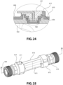
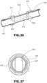
- the ultrasonic flow meter device 600 shown in FIGS. 22-30 is substantially similar to the ultrasonic flow meter 100, 200 discussed above with reference to FIGS. 1-11 except as to certain aspects, which will be discussed in additional detail below.
- the device 600 includes a piping arrangement 601 having a tubular body 602 extending along a longitudinal axis from a first end 603 to a second end 604. An inlet 607 of the piping arrangement 601 is formed at the first end 603, and an outlet 608 is formed at the second end 604.
- the tubular body 602 includes a measurement section 632 disposed within the tubular body 602 intermediate of the first end 603 and the second end 604.
- the tubular body 602 defines a fluid passage 631 extending along the longitudinal axis through the tubular body 602 from the first end 603 to the second end 604.
- the device 600 also includes two ultrasonic transducers 620, 621, which are spaced apart along the longitudinal axis, disposed on opposing sides 605, 606 of the tubular body 602. According to one example, the ultrasonic transducers 620, 621 of the device 600 are the same as the ultrasonic transducers 120a, 120b, 220a, 220b discussed above with reference to the examples of FIGS. 1-11 .
- the device 600 further includes two reflective elements (not shown in FIGS. 22-30 ), which are spaced apart along the longitudinal axis, disposed on the opposing sides 605, 606 of the tubular body 602. According to one example, the reflective elements provided within the device 600 are the same as the reflective elements 230 discussed above with reference to the example of FIGS. 7-11 .
- the piping arrangement 601 of the device 600 includes an outer pipe body 610 made from a metal material.
- the outer pipe body 610 is a round or cylindrical pipe formed with a narrowed oval-shaped portion 613 at the location of the measurement section 632 within the tubular body 602.
- the outer pipe body 610 has an exterior 616 and an interior surface 617.
- the metal material is stainless steel, brass, or bronze, though it is to be appreciated that any suitable metal material, such as iron or aluminum, may be used to form the outer pipe body 610.
- the piping arrangement 601 also includes an inner sleeve 630 made from a polymeric material. The inner sleeve 630 is disposed within the outer pipe body 610.
- the inner sleeve 630 is over molded onto the interior surface 617 of the outer pipe body 610 via an injection molding process.
- the inner sleeve 630 is molded with an interior surface 634 that defines the measurement section 632 and the fluid passage 631 of the piping arrangement 601 such that the negative effects of the metal material of the outer pipe body 610 on the transmission of the ultrasonic wave between the ultrasonic transducers 620, 621 is minimized, if not eliminated.
- the device 600 may further include an outer part similar to the outer part 520 discussed above with reference to FIGS. 12-21 assembled on the exterior 616 of the outer pipe body 610.
- the ultrasonic transducers 620, 621 and the reflective elements are arranged within the piping arrangement 601 to direct an ultrasonic sound wave through the fluid passage 631 in the measurement section 632 of the tubular body 602 from one of the ultrasonic transducers 620 to the other of the ultrasonic transducers 621 in a travel path that is substantially Z-shaped.
- the ultrasonic transducers 620, 621 are disposed at opposing ends of the measurement section 632 on opposing sides 605, 606 of the tubular body 602.
- the outer pipe body 610 includes bands 614, 615 surrounding the exterior 616 of the outer pipe body 610.
- Each of the bands 614, 615 includes a respective aperture 611, 612 defined therein for receiving the transducers 620, 621 therein for supporting the transducers 620, 621 on the piping arrangement 601.
- the inner sleeve 630 is formed within the outer pipe body 610 to define recesses/apertures 635, 636 that extend upwardly into respective apertures 611, 612 of the outer pipe body 610 to define seats for the ultrasonic transducers 620, 621 and place the ultrasonic transducers 620, 621 in communication with the measurement section 632.
- the inner sleeve 630 is formed with a first slot 637 and a second slot 638 defined in the interior surface 634.
- the first and second slots 637, 638 are similar to the slots 217, 218 discussed above with reference to the example of FIGS. 7-11 and are configured to receive the brackets 231 supporting the reflective elements 230 within the fluid passage 631 at the ends of the measurement section 632.
- the transducers 620, 621, reflective elements, and die measurement section 632 of the ultrasonic flow meter device 600 are arranged and configured to direct flow and transmit a Z-shaped ultrasonic wave in the same manner as the corresponding components of the ultrasonic flow meter devices 100, 200 discussed above with reference to FIGS. 1-11 such that the ultrasonic flow meter device 600 operates and measures flow in the same manner as the ultrasonic flow meter devices 100, 200 discussed above with reference to FIGS. 1-11 .
- the measurement section 632 has the same shape and configuration as the measurement sections 105, 205 of the above-discussed devices 100, 200.
- the ultrasonic transducers 620, 621 are configured to communicate with a register (not shown) for measuring flow through the device 600 and transmitting measurement information to a utility, as discussed in detail above.
- the outer pipe body 610 made from the metallic material is provided.
- the outer pipe body 610 has a hollow interior that defines an interior surface 617.
- the outer pipe body 610 is placed within an injection molding machine and an inner sleeve 630 made from a polymeric material is injection molded onto the interior surface 617 of the outer pipe body 610.
- the outer pipe body 610 and the inner over-molded sleeve 630 form a piping arrangement 601 that includes a tubular body 602 extending along a longitudinal axis from a first end 603 to a second end 604 and a measurement section 632 disposed intermediate of the first end 603 and the second end 604.
- the tubular body 602 defines a fluid passage 631 extending along the longitudinal axis through the tubular body 602 from the first end 603 to the second end 604.
- the outer pipe body 610 is shaped to provide definition to the fluid passage 631 and the measurement section 632.
- the outer pipe body 610 is formed with a central narrowed, oval-shaped portion 613 at the location of the measurement section 632.
- the polymeric material of the inner sleeve 630 is molded onto the interior surface 617 of the outer pipe body 610 to coat the interior surface 617 such that the inner sleeve 630 takes on a shape corresponding to the shape of the interior surface 617 of the outer pipe body 610 including the formation of the fluid passage 631, the measurement section 632, and the recesses/apertures 635, 636 for the ultrasonic transducers 620, 621.
- the first and second slots 637, 638 are also formed in the interior surface 634 of the inner sleeve 630 during the injection molding process. It is to be appreciated that during the injection molding process, the polymeric material at the exterior surface 633 of the inner sleeve 630 becomes adhered to or bonds with the material at the interior surface 617 of the outer pipe body 610 so as to completely seal the engagement between the inner sleeve 630 and the outer pipe body 610.
- the at least two ultrasonic transducers 620, 621 are assembled on opposing sides 605, 606 of the tubular body 602 and spaced apart along the longitudinal axis, and at least two reflective elements (not shown in FIGS. 22-30 ) are assembled on the opposing sides 605, 606 of the tubular body 602 and spaced apart along the longitudinal axis.
- FIGS. 28-30 are provided for illustrative purposes only to provide details of the shape features of the inner sleeve 630 by itself.
- the inner sleeve 630 is only formed within the outer pipe body 610 and is not made as a separate component from the outer pipe body 610.
- the specific parameters of the injection molding process for over molding the inner sleeve 630 within the outer pipe body 610 may be selected as being most suitable according those having ordinary skill in the art to form the piping arrangement 601 according to the correct specifications and within tolerances.
- the piping arrangement 650 includes a tubular body 651 formed from an outer metal pipe 652 and an inner sleeve constructed in accordance with the principles discussed above with reference to the tubular body 602 described in connection with FIGS. 22-30 .
- the outer metal pipe 652 includes bands 654, 655 on the exterior thereof that define apertures that accommodate the seats 653 formed in the inner sleeve for positioning of the ultrasonic transducers 620, 621 on the tubular body 651 in communication with the measurement section 632, as discussed above.
- a recess 656 is formed in each of the bands 654, 655 that allows for sensor cables of the ultrasonic transducers 620, 621 to pass through the bands 654, 655 from the apertures 635, 636 to sides of the bands 654, 655 facing toward the longitudinal center of the tubular body 651 without protruding from the outer circumference of the bands 654, 655.
- Plastic rings 657, 658 are also disposed around the exterior of the tubular body 651 and affixed to the sides of the bands 654, 655 facing the longitudinal center of the tubular body 651. As shown in FIGS. 31-33 , the recess 656 may be lined with the plastic material of the inner sleeve.
- the sensor cables of the ultrasonic transducers 620, 621 are electrically insulated from the metal material of the bands 654, 655 of the outer metal pipe 652 as they pass through and away from the bands 654, 655 toward the longitudinal center of the tubular body 651.
Landscapes
- Physics & Mathematics (AREA)
- Fluid Mechanics (AREA)
- General Physics & Mathematics (AREA)
- Electromagnetism (AREA)
- Measuring Volume Flow (AREA)
Claims (13)
- Eine Ultraschall-Durchflussmessvorrichtung (600), umfassend:eine Rohrleitungsanordnung (601, 650) umfassend einen röhrenförmigen Körper (602, 651), der sich entlang einer Längsachse (L) von einem ersten Ende (603) zu einem zweiten Ende (604) erstreckt und einen Messabschnitt (632) umfasst, der zwischen dem ersten Ende (603) und dem zweiten Ende (604) angeordnet ist, wobei der röhrenförmige Körper (602, 651) einen Fluidkanal (631) definiert, der sich entlang der Längsachse (L) durch den röhrenförmigen Körper (602, 651) von dem ersten Ende (603) zu dem zweiten Ende (604) erstreckt;mindestens zwei Ultraschallwandler (620, 621), die auf gegenüberliegenden Seiten des rohrförmigen Körpers (602, 651) angeordnet und entlang der Längsachse (L) beabstandet sind; undmindestens zwei reflektierende Elemente (230), die an den gegenüberliegenden Seiten (605, 606) des rohrförmigen Körpers (602, 651) angeordnet und entlang der Längsachse (L) beabstandet sind,wobei die Rohrleitungsanordnung (601, 650) umfasst:einen äußeren Rohrkörper (610, 652) undeine Innenhülse (630) aus einem Polymermaterial, wobei die Innenhülse (630) innerhalb des äußeren Rohrkörpers (610, 652) angeordnet ist, undwobei die Innenhülse (630) den Messabschnitt (632) und den Fluidkanal (631) der Rohrleitungsanordnung (601, 650) definiert,dadurch gekennzeichnet, dassder äußere Rohrkörper (610, 652) aus einem metallischen Material geformt ist, und wobei die Innenhülse (630) innerhalb des äußeren Rohrkörpers (610, 652) überformt ist, und jedes der mindestens zwei reflektierenden Elemente (230) auf einer jeweiligen Halterung (231) angeordnet ist, die in den Fluidkanal (631) eingesetzt ist, und, vorzugsweise, jede Halterung (231) herausnehmbar in einen Schlitz (637, 638) eingesetzt ist, der in einer Innenfläche (634) der inneren Hülse (630) definiert ist und sich entlang der Längsachse (L) von einem jeweiligen des ersten Endes (603) und des zweiten Endes (604) des rohrförmigen Körpers (602, 652) zu dem Messabschnitt (632) erstreckt.
- Die Ultraschall-Durchflussmessvorrichtung (600) nach Anspruch 1, wobei der äußere Rohrkörper (610) einen verengten Abschnitt (613) aufweist, der den Messabschnitt (632) in der überformten inneren Hülse (630) definiert.
- Die Ultraschall-Durchflussmessvorrichtung (600) nach Anspruch 2, wobei der Fluidkanal (631) eine kreisförmige Form am ersten Ende (603) und am zweiten Ende (604) und eine oblonge kreisförmige Form im Messabschnitt (632) aufweist, und
wobei eine erste Breite (w1) des Fluidkanals (631) am ersten Ende (603) und am zweiten Ende (604) größer ist als eine zweite Breite (w2) des Fluidkanals (631) im Messabschnitt (632), und eine Querschnittsfläche des Fluidkanal (631) am ersten Ende (603) und am zweiten Ende (604) die gleiche ist wie eine Querschnittsfläche des Fluidkanals (631) im Messabschnitt (632). - Die Ultraschall-Durchflussmessvorrichtung (600) nach Anspruch 1, wobei die mindestens zwei Ultraschallwandler (620, 621) so konfiguriert sind, dass sie eine Ultraschallwelle erzeugen und/oder empfangen, und die mindestens zwei reflektierenden Elemente (230) so konfiguriert sind, dass sie die Ultraschallwelle durch den Fluidkanal (631) in dem Messabschnitt (632) des rohrförmigen Körpers (602, 651) von einem der mindestens zwei Ultraschallwandler (620, 621) zu einem anderen der mindestens zwei Ultraschallwandler (620, 621) in einem im Wesentlichen Z-förmigen Ausbreitungsweg leiten.
- Ultraschall-Durchflussmessvorrichtung (600) nach Anspruch 1, wobei das polymere Material der Innenhülse (630) sich mit dem metallischen Material des äußeren Rohrkörpers (610, 652) verbindet, um einen abgedichteten Eingriff zwischen der Innenhülse (630) und dem äußeren Rohrkörper (610, 652) zu bilden, und/oder
wobei das metallische Material rostfreien Stahl, Messing oder Bronze umfasst. - Die Ultraschall-Durchflussmessvorrichtung (600) nach Anspruch 1, wobei der äußere Rohrkörper (610, 652) mindestens zwei darin definierte Öffnungen (611, 612) aufweist und die innere Hülse (630) mindestens zwei darin ausgebildete Aufnahmen (635, 636, 653) aufweist, die sich jeweils in eine entsprechende der mindestens zwei Öffnungen (611, 612) erstrecken, undwobei die mindestens zwei Öffnungen (611, 612) in dem äußeren Rohrkörper (610, 652) und die mindestens zwei Aufnahmen (635, 636, 653) in der inneren Hülse (630) so konfiguriert sind, dass sie die mindestens zwei Ultraschallwandler (620, 621) darin aufnehmen und stützen und die mindestens zwei Ultraschallwandler (620, 621) in Kommunikation mit dem Messabschnitt (632) bringen, und vorzugsweise,wobei der äußere Rohrkörper (652) mindestens zwei Ausnehmungen (656) aufweist, die darin angrenzend an die mindestens zwei Öffnungen (611, 612) definiert sind, und das polymere Material der inneren Hülse (630) die mindestens zwei Ausnehmungen (656) auskleidet, wobei die mindestens zwei Ausnehmungen so konfiguriert sind, dass Sensorkabel von den mindestens zwei Ultraschallwandlern (620, 621) durch sie hindurchgeführt werden können.
- Ein Verfahren zur Herstellung einer Ultraschall-Durchflussmessvorrichtung (600), wobei das Verfahren umfasst:Bereitstellen eines äußeren Rohrkörpers (610, 652), der aus einem metallischen Material geformt ist, wobei der äußere Rohrkörper (610, 652) einen hohlen Innenraum aufweist, der eine Innenfläche (617) definiert;Spritzgießen einer Innenhülse (630) aus einem Polymermaterial auf die Innenfläche (617) des äußeren Rohrkörpers (610, 652), wobei der äußere Rohrkörper (610, 652) und die Innenhülse (630) eine Rohrleitungsanordnung (601, 650) bilden, die einen rohrförmigen Körper (602,651) umfasst, der sich entlang einer Längsachse (L) von einem ersten Ende (603) zu einem zweiten Ende (604) erstreckt und einen Messabschnitt (632) einschließt, der zwischen dem ersten Ende (603) und dem zweiten Ende (604) angeordnet ist, wobei der rohrförmige Körper (602, 651) einen Fluidkanal (631) definiert, der sich entlang der Längsachse (L) durch den rohrförmigen Körper (602, 651) von dem ersten Ende (603) zu dem zweiten Ende (604) erstreckt;Anbringen von mindestens zwei Ultraschallwandlern (620, 621) an gegenüberliegenden Seiten (605, 606) des rohrförmigen Körpers (602, 651) und beabstandet entlang der Längsachse (L); undAnbringen von mindestens zwei reflektierenden Elementen (230) an den gegenüberliegenden Seiten (605, 606) des rohrförmigen Körpers (602, 651), die entlang der Längsachse (L) voneinander beabstandet sind,wobeijedes der mindestens zwei reflektierenden Elemente (230) auf einer jeweiligen Halterung (231) angeordnet ist, der in den Fluidkanal (631) eingesetzt ist, und vorzugsweise jede Halterung (231) herausnehmbar in einen Schlitz (637, 638) eingesetzt ist, der in einer Innenfläche (634) der inneren Hülse (630) definiert ist und sich entlang der Längsachse (L) von einem jeweiligen des ersten Endes (603) und des zweiten Endes (604) des rohrförmigen Körpers (602, 651) zu dem Messabschnitt (632) erstreckt.
- Verfahren nach Anspruch 7, wobei die Innenhülse (630) auf die Innenfläche (617) des äußeren Rohrkörpers (610, 652) spritzgegossen wird, um einen dichten Eingriff zwischen der Innenhülse (630) und dem äußeren Rohrkörper (610, 652) zu bilden, und/oderwobei der äußere Rohrkörper (610, 652) einen verengten Teil (613) aufweist, der den Messabschnitt (632) in der geformten inneren Hülse (630) definiert, und/oderwobei das metallische Material rostfreien Stahl, Messing oder Bronze umfasst.
- Verfahren nach Anspruch 8, wobei der Fluidkanal (631) am ersten Ende (603) und am zweiten Ende (604) eine kreisförmige Form und im Messabschnitt (632) eine oblonge Kreisform aufweist, und
wobei eine erste Breite (w1) des Fluidkanal (631) am ersten Ende (603) und am zweiten Ende (604) größer ist als eine zweite Breite (w2) des Fluidkanals (631) im Messabschnitt (632), und eine Querschnittsfläche des Fluidkanals (631) am ersten Ende (603) und am zweiten Ende (604) dieselbe ist wie eine Querschnittsfläche des Fluidkanals (631) im Messabschnitt (632). - Verfahren nach Anspruch 7, wobei die mindestens zwei Ultraschallwandler (620, 621) so konfiguriert sind, dass sie eine Ultraschallwelle erzeugen und/oder empfangen, und die mindestens zwei reflektierenden Elemente (230) so konfiguriert sind, dass sie die Ultraschallwelle durch den Fluidkanal (631) im Messabschnitt (632) des rohrförmigen Körpers (602,651) von einem der mindestens zwei Ultraschallwandler (620, 621) zu einem anderen der mindestens zwei Ultraschallwandler (620, 621) in einem im Wesentlichen Z-förmigen Laufweg zu leiten.
- Verfahren nach Anspruch 7, wobei der äußere Rohrkörper (610, 652) mindestens zwei darin definierte Öffnungen (611, 612) aufweist und während des Spritzgießschritts die innere Hülse (630) so geformt wird, dass sie mindestens zwei Aufnahmen (635, 636, 653) bildet, die sich jeweils in eine entsprechende der mindestens zwei Öffnungen (611, 612) erstrecken, und wobei die mindestens zwei Öffnungen (611, 612) in dem äußeren Rohrkörper (610, 652) und die mindestens zwei Aufnahmen (635, 636, 653) in der inneren Hülse (630) so konfiguriert sind, dass sie die mindestens zwei Ultraschallwandler (620, 621) darin aufnehmen und stützen und die mindestens zwei Ultraschallwandler (620, 621) in Kommunikation mit dem Messabschnitt (632) bringen, und vorzugsweise,
wobei der äußere Rohrkörper (610, 652) mindestens zwei Ausnehmungen (656) aufweist, die darin benachbart zu den mindestens zwei Öffnungen (611, 612) definiert sind, und während des Spritzgießschritts die innere Hülse (630) so geformt wird, dass sie die mindestens zwei Ausnehmungen (656) in dem äußeren Rohrkörper (610, 652) auskleidet, wobei die mindestens zwei Ausnehmungen (656) so konfiguriert sind, dass Sensorkabel von den mindestens zwei Ultraschallwandlern (620, 621) durch sie hindurchgeführt werden können. - Die Ultraschall-Durchflussmessvorrichtung (500) nach Anspruch 1,wobei die Rohrleitungsanordnung (501) ferner Folgendes umfasst ein Befestigungselement (525), das so konfiguriert ist, dass es die innere Hülse (530) innerhalb des äußeren Rohrkörpers (510) sichert,wobei der äußere Rohrkörper (510) und die innere Hülse (530) entsprechende Öffnungen (511, 512, 535, 536) aufweisen, die Aufnahmen für die mindestens zwei Ultraschallwandler (523, 524) definieren und die die Ultraschallwandler (523, 524) in Verbindung mit dem Messabschnitt (532) bringen, undwobei der äußere Rohrkörper (510) eine Öffnung (513) und die innere Hülse (530) eine entsprechende Aussparung (537) aufweist, die zur Aufnahme des Befestigungselements (525) konfiguriert ist.
- Die Ultraschall-Durchflussmessvorrichtung (500) nach Anspruch 12, wobei das metallische Material rostfreien Stahl, Messing oder Bronze umfasst; und/oder ferner umfassend eine Dichtung (538), die zwischen dem äußeren Rohrkörper (510) und der inneren Hülse (530) angeordnet ist, wobei die Dichtung (538) so konfiguriert ist, dass sie einen Eingriff zwischen einer Innenfläche (517) des äußeren Rohrkörpers (510) und einer Außenfläche (533) der inneren Hülse (530) abdichtet.
Applications Claiming Priority (3)
| Application Number | Priority Date | Filing Date | Title |
|---|---|---|---|
| US201762598719P | 2017-12-14 | 2017-12-14 | |
| US16/216,700 US10823597B2 (en) | 2017-12-14 | 2018-12-11 | Ultrasonic water meter including a metallic outer body and polymeric inner lining sleeve |
| PCT/IB2018/059960 WO2019116269A1 (en) | 2017-12-14 | 2018-12-12 | Ultrasonic water meter made of multiple materials |
Publications (3)
| Publication Number | Publication Date |
|---|---|
| EP3847423A1 EP3847423A1 (de) | 2021-07-14 |
| EP3847423A4 EP3847423A4 (de) | 2022-07-27 |
| EP3847423B1 true EP3847423B1 (de) | 2024-12-25 |
Family
ID=66815900
Family Applications (1)
| Application Number | Title | Priority Date | Filing Date |
|---|---|---|---|
| EP18889063.6A Active EP3847423B1 (de) | 2017-12-14 | 2018-12-12 | Ultraschallwasserzähler aus mehreren materialien |
Country Status (4)
| Country | Link |
|---|---|
| US (1) | US10823597B2 (de) |
| EP (1) | EP3847423B1 (de) |
| ES (1) | ES3015232T3 (de) |
| WO (1) | WO2019116269A1 (de) |
Families Citing this family (7)
| Publication number | Priority date | Publication date | Assignee | Title |
|---|---|---|---|---|
| TW201946763A (zh) * | 2018-05-16 | 2019-12-16 | 日商琉Sok股份有限公司 | 超音波流量計的測量管路部的製造方法 |
| CN110567542B (zh) * | 2019-09-29 | 2025-02-25 | 宁波东海集团有限公司 | 一种超声波换能器安装装置及应用该安装装置的超声波水表 |
| CN115003991B (zh) * | 2020-01-22 | 2026-02-27 | 贝克顿·迪金森公司 | 在超声波流量计中联结联接器和流量管的装置和方法 |
| IT202000013537A1 (it) * | 2020-06-08 | 2021-12-08 | Maddalena S P A | Dispositivo di misura ad ultrasuoni, particolarmente per la misurazione del consumo di acqua e/o di calorie. |
| US11906337B2 (en) * | 2021-02-15 | 2024-02-20 | Honeywell International Inc. | Inline transducer housing assembly |
| US12292317B2 (en) | 2022-02-28 | 2025-05-06 | Mueller International, Llc | Ultrasonic flow meter assembly |
| CN118500488B (zh) * | 2024-07-09 | 2024-10-18 | 浙江蓝宝石仪表科技有限公司 | 嵌套型气体超声流量计及制备方法 |
Family Cites Families (20)
| Publication number | Priority date | Publication date | Assignee | Title |
|---|---|---|---|---|
| US5277070A (en) | 1991-08-01 | 1994-01-11 | Xecutek Corporation | Ultrasonic gas flow measurement method and apparatus |
| DE19861073A1 (de) * | 1998-03-02 | 1999-11-04 | Georg F Wagner | Durchflußmeßvorrichtung |
| US6330831B1 (en) * | 1998-10-20 | 2001-12-18 | Panametrics, Inc. | Stream-cleaned differential reflection coefficient sensor |
| DE19944411A1 (de) | 1999-09-16 | 2001-04-12 | Kundo Systemtechnik Gmbh | Ultraschall-Durchflußmesser |
| DE10120355A1 (de) | 2001-04-26 | 2002-10-31 | Elster Gmbh | Verfahren und Vorrichtung zur Ultraschall-Durchflußmessung von Fluiden |
| DE10254053B4 (de) * | 2002-11-19 | 2016-12-22 | Endress + Hauser Flowtec Ag | Verfahren und Vorrichtung zur Bestimmung und/oder Überwachung eines Volumen- und/oder Massenstroms |
| DE102004010408A1 (de) * | 2004-03-01 | 2005-09-22 | Hydrometer Gmbh | Ultraschallzähler zur Bestimmung der Durchflussmenge eines strömenden Mediums |
| AT6511U3 (de) * | 2003-07-16 | 2004-09-27 | Avl List Gmbh | Ultraschall-gasdurchflusssensor sowie vorrichtung zur messung von abgas-strömungen von verbrennungskraftmaschinen sowie ein verfahren zur ermittlung des durchflusses von gasen |
| CH701728B1 (de) * | 2005-12-06 | 2011-03-15 | Digmesa Ag | Ultraschallmessanordnung mit einer Ultraschallmessstrecke aus Kunststoff, Verfahren zur Durchflussmessung und Verfahren zur Herstellung einer Ultraschallmessstrecke. |
| US7523675B2 (en) | 2006-06-02 | 2009-04-28 | Endress + Hauser Flowtec Ag | In-line measuring device with measuring tube lined internally with polyurethane and method for manufacture thereof |
| WO2008042290A2 (en) | 2006-09-29 | 2008-04-10 | Rosemount Inc. | Magnetic flowmeter with verification |
| GB2462639B (en) | 2008-08-14 | 2013-02-27 | Abb Ltd | Electromagnetic flow meter |
| CN102944695B (zh) * | 2008-11-05 | 2014-12-10 | 松下电器产业株式会社 | 多层流路部件及使用它的超声波式流体计测装置 |
| JP2012008108A (ja) * | 2010-06-28 | 2012-01-12 | Toshiba Corp | 電磁流量計 |
| EP2682719A1 (de) * | 2012-07-05 | 2014-01-08 | Kamstrup A/S | Durchflussmesser mit ununterbrochener Innenauskleidung |
| WO2015000487A1 (en) | 2013-07-02 | 2015-01-08 | Kamstrup A/S | Flow meter with unbroken liner |
| DE102013107895A1 (de) | 2013-07-24 | 2015-01-29 | Endress + Hauser Flowtec Ag | Durchflussmessgerät |
| CN105444825B (zh) * | 2014-05-31 | 2019-06-14 | 通用电气公司 | 超声装置以及用该超声装置来测量流体流量的方法 |
| JP2016095206A (ja) * | 2014-11-13 | 2016-05-26 | 株式会社東芝 | 電磁流量計 |
| US9714855B2 (en) * | 2015-01-26 | 2017-07-25 | Arad Ltd. | Ultrasonic water meter |
-
2018
- 2018-12-11 US US16/216,700 patent/US10823597B2/en active Active
- 2018-12-12 ES ES18889063T patent/ES3015232T3/es active Active
- 2018-12-12 EP EP18889063.6A patent/EP3847423B1/de active Active
- 2018-12-12 WO PCT/IB2018/059960 patent/WO2019116269A1/en not_active Ceased
Also Published As
| Publication number | Publication date |
|---|---|
| US10823597B2 (en) | 2020-11-03 |
| EP3847423A1 (de) | 2021-07-14 |
| ES3015232T3 (en) | 2025-04-30 |
| US20190186968A1 (en) | 2019-06-20 |
| WO2019116269A1 (en) | 2019-06-20 |
| EP3847423A4 (de) | 2022-07-27 |
Similar Documents
| Publication | Publication Date | Title |
|---|---|---|
| US10823597B2 (en) | Ultrasonic water meter including a metallic outer body and polymeric inner lining sleeve | |
| EP3256821B1 (de) | Ultraschallwassermesser | |
| KR101888188B1 (ko) | 누수감지가 가능한 초음파 수도미터기, 이를 구비한 누수 감지시스템 및 이를 이용한 누수위치 감지방법 | |
| EP3172539B1 (de) | Rohrleitungs-einsatz für ein ultraschall-durchflussmessgerät | |
| RU2598976C1 (ru) | Система и способ для ультразвукового измерения с использованием фитинга диафрагменного расходомера | |
| CN109211339A (zh) | 用于操作流量计的方法 | |
| US11650087B2 (en) | Ultrasonic meter including one or more pairs of ultrasonic transducers and two or more protrusions arranged to exclude fluid from non-sampled volume | |
| CN102192767B (zh) | 用于测量流体流动速度的超声波测量装置和方法 | |
| KR101780780B1 (ko) | 수도계량기용 초음파 유량계 | |
| CN109477741A (zh) | 具有测量通道的流量计 | |
| CN104641118B (zh) | 包括流量计的回转泵 | |
| KR102355949B1 (ko) | 소구경용 초음파유량계 | |
| US20200386590A1 (en) | Ultrasonic Flowmeter Element | |
| CN105387898B (zh) | 具有插入到壳体中的测量插件的流量计 | |
| US11614352B2 (en) | Consumption meter with ultrasonic flow measurement | |
| KR101622566B1 (ko) | 초음파 시간차 유량측정 방식을 이용한 초음파 수도미터 | |
| US11885654B2 (en) | Ultrasonic flowmeter, use of an ultrasonic flowmeter in a shut-off device and shut-off device | |
| KR101163567B1 (ko) | 유속/유량측정용 정류반사체, 유속/유량측정용 정류반사관 및 이를 구비한 초음파 유량계 | |
| KR102796299B1 (ko) | 초음파 유량계 | |
| EP3825660B1 (de) | Modularer ultraschallverbrauchszähler | |
| JP4453341B2 (ja) | 超音波流量計 | |
| KR100927449B1 (ko) | 음파수위측정방법 | |
| US20260022957A1 (en) | Multi-part assembly for retrofitting into a passage of a mechanical flow meter | |
| KR102478319B1 (ko) | 유량관용 슬롯부재 | |
| KR102756370B1 (ko) | 누수탐지 일체형 초음파 수도미터 |
Legal Events
| Date | Code | Title | Description |
|---|---|---|---|
| STAA | Information on the status of an ep patent application or granted ep patent |
Free format text: STATUS: THE INTERNATIONAL PUBLICATION HAS BEEN MADE |
|
| STAA | Information on the status of an ep patent application or granted ep patent |
Free format text: STATUS: THE APPLICATION IS DEEMED TO BE WITHDRAWN |
|
| STAA | Information on the status of an ep patent application or granted ep patent |
Free format text: STATUS: THE INTERNATIONAL PUBLICATION HAS BEEN MADE |
|
| PUAI | Public reference made under article 153(3) epc to a published international application that has entered the european phase |
Free format text: ORIGINAL CODE: 0009012 |
|
| STAA | Information on the status of an ep patent application or granted ep patent |
Free format text: STATUS: REQUEST FOR EXAMINATION WAS MADE |
|
| 17P | Request for examination filed |
Effective date: 20210511 |
|
| AK | Designated contracting states |
Kind code of ref document: A1 Designated state(s): AL AT BE BG CH CY CZ DE DK EE ES FI FR GB GR HR HU IE IS IT LI LT LU LV MC MK MT NL NO PL PT RO RS SE SI SK SM TR |
|
| A4 | Supplementary search report drawn up and despatched |
Effective date: 20220624 |
|
| RIC1 | Information provided on ipc code assigned before grant |
Ipc: G01F 15/00 20060101ALI20220620BHEP Ipc: G01P 5/24 20060101ALI20220620BHEP Ipc: G01F 1/66 20060101AFI20220620BHEP |
|
| GRAP | Despatch of communication of intention to grant a patent |
Free format text: ORIGINAL CODE: EPIDOSNIGR1 |
|
| STAA | Information on the status of an ep patent application or granted ep patent |
Free format text: STATUS: GRANT OF PATENT IS INTENDED |
|
| INTG | Intention to grant announced |
Effective date: 20240327 |
|
| GRAJ | Information related to disapproval of communication of intention to grant by the applicant or resumption of examination proceedings by the epo deleted |
Free format text: ORIGINAL CODE: EPIDOSDIGR1 |
|
| STAA | Information on the status of an ep patent application or granted ep patent |
Free format text: STATUS: REQUEST FOR EXAMINATION WAS MADE |
|
| GRAP | Despatch of communication of intention to grant a patent |
Free format text: ORIGINAL CODE: EPIDOSNIGR1 |
|
| STAA | Information on the status of an ep patent application or granted ep patent |
Free format text: STATUS: GRANT OF PATENT IS INTENDED |
|
| INTC | Intention to grant announced (deleted) | ||
| INTG | Intention to grant announced |
Effective date: 20240710 |
|
| GRAS | Grant fee paid |
Free format text: ORIGINAL CODE: EPIDOSNIGR3 |
|
| GRAA | (expected) grant |
Free format text: ORIGINAL CODE: 0009210 |
|
| STAA | Information on the status of an ep patent application or granted ep patent |
Free format text: STATUS: THE PATENT HAS BEEN GRANTED |
|
| AK | Designated contracting states |
Kind code of ref document: B1 Designated state(s): AL AT BE BG CH CY CZ DE DK EE ES FI FR GB GR HR HU IE IS IT LI LT LU LV MC MK MT NL NO PL PT RO RS SE SI SK SM TR |
|
| REG | Reference to a national code |
Ref country code: GB Ref legal event code: FG4D |
|
| REG | Reference to a national code |
Ref country code: CH Ref legal event code: EP |
|
| REG | Reference to a national code |
Ref country code: DE Ref legal event code: R096 Ref document number: 602018078020 Country of ref document: DE |
|
| REG | Reference to a national code |
Ref country code: IE Ref legal event code: FG4D |
|
| REG | Reference to a national code |
Ref country code: LT Ref legal event code: MG9D |
|
| PG25 | Lapsed in a contracting state [announced via postgrant information from national office to epo] |
Ref country code: HR Free format text: LAPSE BECAUSE OF FAILURE TO SUBMIT A TRANSLATION OF THE DESCRIPTION OR TO PAY THE FEE WITHIN THE PRESCRIBED TIME-LIMIT Effective date: 20241225 |
|
| PG25 | Lapsed in a contracting state [announced via postgrant information from national office to epo] |
Ref country code: FI Free format text: LAPSE BECAUSE OF FAILURE TO SUBMIT A TRANSLATION OF THE DESCRIPTION OR TO PAY THE FEE WITHIN THE PRESCRIBED TIME-LIMIT Effective date: 20241225 |
|
| PG25 | Lapsed in a contracting state [announced via postgrant information from national office to epo] |
Ref country code: BG Free format text: LAPSE BECAUSE OF FAILURE TO SUBMIT A TRANSLATION OF THE DESCRIPTION OR TO PAY THE FEE WITHIN THE PRESCRIBED TIME-LIMIT Effective date: 20241225 |
|
| PG25 | Lapsed in a contracting state [announced via postgrant information from national office to epo] |
Ref country code: NO Free format text: LAPSE BECAUSE OF FAILURE TO SUBMIT A TRANSLATION OF THE DESCRIPTION OR TO PAY THE FEE WITHIN THE PRESCRIBED TIME-LIMIT Effective date: 20250325 |
|
| PG25 | Lapsed in a contracting state [announced via postgrant information from national office to epo] |
Ref country code: LV Free format text: LAPSE BECAUSE OF FAILURE TO SUBMIT A TRANSLATION OF THE DESCRIPTION OR TO PAY THE FEE WITHIN THE PRESCRIBED TIME-LIMIT Effective date: 20241225 Ref country code: GR Free format text: LAPSE BECAUSE OF FAILURE TO SUBMIT A TRANSLATION OF THE DESCRIPTION OR TO PAY THE FEE WITHIN THE PRESCRIBED TIME-LIMIT Effective date: 20250326 |
|
| PG25 | Lapsed in a contracting state [announced via postgrant information from national office to epo] |
Ref country code: RS Free format text: LAPSE BECAUSE OF FAILURE TO SUBMIT A TRANSLATION OF THE DESCRIPTION OR TO PAY THE FEE WITHIN THE PRESCRIBED TIME-LIMIT Effective date: 20250325 |
|
| REG | Reference to a national code |
Ref country code: NL Ref legal event code: MP Effective date: 20241225 Ref country code: ES Ref legal event code: FG2A Ref document number: 3015232 Country of ref document: ES Kind code of ref document: T3 Effective date: 20250430 |
|
| RAP4 | Party data changed (patent owner data changed or rights of a patent transferred) |
Owner name: ARAD LTD. |
|
| PG25 | Lapsed in a contracting state [announced via postgrant information from national office to epo] |
Ref country code: NL Free format text: LAPSE BECAUSE OF FAILURE TO SUBMIT A TRANSLATION OF THE DESCRIPTION OR TO PAY THE FEE WITHIN THE PRESCRIBED TIME-LIMIT Effective date: 20241225 |
|
| REG | Reference to a national code |
Ref country code: AT Ref legal event code: MK05 Ref document number: 1754505 Country of ref document: AT Kind code of ref document: T Effective date: 20241225 |
|
| PG25 | Lapsed in a contracting state [announced via postgrant information from national office to epo] |
Ref country code: SM Free format text: LAPSE BECAUSE OF FAILURE TO SUBMIT A TRANSLATION OF THE DESCRIPTION OR TO PAY THE FEE WITHIN THE PRESCRIBED TIME-LIMIT Effective date: 20241225 |
|
| PG25 | Lapsed in a contracting state [announced via postgrant information from national office to epo] |
Ref country code: PL Free format text: LAPSE BECAUSE OF FAILURE TO SUBMIT A TRANSLATION OF THE DESCRIPTION OR TO PAY THE FEE WITHIN THE PRESCRIBED TIME-LIMIT Effective date: 20241225 |
|
| PG25 | Lapsed in a contracting state [announced via postgrant information from national office to epo] |
Ref country code: IS Free format text: LAPSE BECAUSE OF FAILURE TO SUBMIT A TRANSLATION OF THE DESCRIPTION OR TO PAY THE FEE WITHIN THE PRESCRIBED TIME-LIMIT Effective date: 20250425 |
|
| PG25 | Lapsed in a contracting state [announced via postgrant information from national office to epo] |
Ref country code: PT Free format text: LAPSE BECAUSE OF FAILURE TO SUBMIT A TRANSLATION OF THE DESCRIPTION OR TO PAY THE FEE WITHIN THE PRESCRIBED TIME-LIMIT Effective date: 20250428 |
|
| PG25 | Lapsed in a contracting state [announced via postgrant information from national office to epo] |
Ref country code: EE Free format text: LAPSE BECAUSE OF FAILURE TO SUBMIT A TRANSLATION OF THE DESCRIPTION OR TO PAY THE FEE WITHIN THE PRESCRIBED TIME-LIMIT Effective date: 20241225 |
|
| PG25 | Lapsed in a contracting state [announced via postgrant information from national office to epo] |
Ref country code: AT Free format text: LAPSE BECAUSE OF FAILURE TO SUBMIT A TRANSLATION OF THE DESCRIPTION OR TO PAY THE FEE WITHIN THE PRESCRIBED TIME-LIMIT Effective date: 20241225 Ref country code: RO Free format text: LAPSE BECAUSE OF FAILURE TO SUBMIT A TRANSLATION OF THE DESCRIPTION OR TO PAY THE FEE WITHIN THE PRESCRIBED TIME-LIMIT Effective date: 20241225 |
|
| PG25 | Lapsed in a contracting state [announced via postgrant information from national office to epo] |
Ref country code: SK Free format text: LAPSE BECAUSE OF FAILURE TO SUBMIT A TRANSLATION OF THE DESCRIPTION OR TO PAY THE FEE WITHIN THE PRESCRIBED TIME-LIMIT Effective date: 20241225 |
|
| PG25 | Lapsed in a contracting state [announced via postgrant information from national office to epo] |
Ref country code: CZ Free format text: LAPSE BECAUSE OF FAILURE TO SUBMIT A TRANSLATION OF THE DESCRIPTION OR TO PAY THE FEE WITHIN THE PRESCRIBED TIME-LIMIT Effective date: 20241225 |
|
| PG25 | Lapsed in a contracting state [announced via postgrant information from national office to epo] |
Ref country code: SE Free format text: LAPSE BECAUSE OF FAILURE TO SUBMIT A TRANSLATION OF THE DESCRIPTION OR TO PAY THE FEE WITHIN THE PRESCRIBED TIME-LIMIT Effective date: 20241225 |
|
| REG | Reference to a national code |
Ref country code: DE Ref legal event code: R097 Ref document number: 602018078020 Country of ref document: DE |
|
| PG25 | Lapsed in a contracting state [announced via postgrant information from national office to epo] |
Ref country code: DK Free format text: LAPSE BECAUSE OF FAILURE TO SUBMIT A TRANSLATION OF THE DESCRIPTION OR TO PAY THE FEE WITHIN THE PRESCRIBED TIME-LIMIT Effective date: 20241225 |
|
| PGFP | Annual fee paid to national office [announced via postgrant information from national office to epo] |
Ref country code: FR Payment date: 20250930 Year of fee payment: 8 |
|
| PLBE | No opposition filed within time limit |
Free format text: ORIGINAL CODE: 0009261 |
|
| STAA | Information on the status of an ep patent application or granted ep patent |
Free format text: STATUS: NO OPPOSITION FILED WITHIN TIME LIMIT |
|
| 26N | No opposition filed |
Effective date: 20250926 |
|
| PGFP | Annual fee paid to national office [announced via postgrant information from national office to epo] |
Ref country code: DE Payment date: 20250930 Year of fee payment: 8 |
|
| PGFP | Annual fee paid to national office [announced via postgrant information from national office to epo] |
Ref country code: GB Payment date: 20251001 Year of fee payment: 8 |
|
| PGFP | Annual fee paid to national office [announced via postgrant information from national office to epo] |
Ref country code: IT Payment date: 20251121 Year of fee payment: 8 |
|
| PGFP | Annual fee paid to national office [announced via postgrant information from national office to epo] |
Ref country code: ES Payment date: 20260112 Year of fee payment: 8 |