EP3847401B1 - Refrigerant leak detection system - Google Patents
Refrigerant leak detection system Download PDFInfo
- Publication number
- EP3847401B1 EP3847401B1 EP19770239.2A EP19770239A EP3847401B1 EP 3847401 B1 EP3847401 B1 EP 3847401B1 EP 19770239 A EP19770239 A EP 19770239A EP 3847401 B1 EP3847401 B1 EP 3847401B1
- Authority
- EP
- European Patent Office
- Prior art keywords
- compressor
- valve
- refrigerant
- evaporator
- inlet
- Prior art date
- Legal status (The legal status is an assumption and is not a legal conclusion. Google has not performed a legal analysis and makes no representation as to the accuracy of the status listed.)
- Active
Links
Images



Classifications
-
- F—MECHANICAL ENGINEERING; LIGHTING; HEATING; WEAPONS; BLASTING
- F25—REFRIGERATION OR COOLING; COMBINED HEATING AND REFRIGERATION SYSTEMS; HEAT PUMP SYSTEMS; MANUFACTURE OR STORAGE OF ICE; LIQUEFACTION SOLIDIFICATION OF GASES
- F25B—REFRIGERATION MACHINES, PLANTS OR SYSTEMS; COMBINED HEATING AND REFRIGERATION SYSTEMS; HEAT PUMP SYSTEMS
- F25B1/00—Compression machines, plants or systems with non-reversible cycle
-
- B—PERFORMING OPERATIONS; TRANSPORTING
- B60—VEHICLES IN GENERAL
- B60H—ARRANGEMENTS OF HEATING, COOLING, VENTILATING OR OTHER AIR-TREATING DEVICES SPECIALLY ADAPTED FOR PASSENGER OR GOODS SPACES OF VEHICLES
- B60H1/00—Heating, cooling or ventilating devices
- B60H1/00485—Valves for air-conditioning devices, e.g. thermostatic valves
-
- B—PERFORMING OPERATIONS; TRANSPORTING
- B60—VEHICLES IN GENERAL
- B60H—ARRANGEMENTS OF HEATING, COOLING, VENTILATING OR OTHER AIR-TREATING DEVICES SPECIALLY ADAPTED FOR PASSENGER OR GOODS SPACES OF VEHICLES
- B60H1/00—Heating, cooling or ventilating devices
- B60H1/32—Cooling devices
- B60H1/3204—Cooling devices using compression
- B60H1/3205—Control means therefor
-
- B—PERFORMING OPERATIONS; TRANSPORTING
- B60—VEHICLES IN GENERAL
- B60H—ARRANGEMENTS OF HEATING, COOLING, VENTILATING OR OTHER AIR-TREATING DEVICES SPECIALLY ADAPTED FOR PASSENGER OR GOODS SPACES OF VEHICLES
- B60H1/00—Heating, cooling or ventilating devices
- B60H1/32—Cooling devices
- B60H1/3204—Cooling devices using compression
- B60H1/3225—Cooling devices using compression characterised by safety arrangements, e.g. compressor anti-seizure means or by signalling devices
-
- B—PERFORMING OPERATIONS; TRANSPORTING
- B60—VEHICLES IN GENERAL
- B60H—ARRANGEMENTS OF HEATING, COOLING, VENTILATING OR OTHER AIR-TREATING DEVICES SPECIALLY ADAPTED FOR PASSENGER OR GOODS SPACES OF VEHICLES
- B60H1/00—Heating, cooling or ventilating devices
- B60H1/32—Cooling devices
- B60H1/3204—Cooling devices using compression
- B60H1/3227—Cooling devices using compression characterised by the arrangement or the type of heat exchanger, e.g. condenser, evaporator
-
- B—PERFORMING OPERATIONS; TRANSPORTING
- B60—VEHICLES IN GENERAL
- B60H—ARRANGEMENTS OF HEATING, COOLING, VENTILATING OR OTHER AIR-TREATING DEVICES SPECIALLY ADAPTED FOR PASSENGER OR GOODS SPACES OF VEHICLES
- B60H1/00—Heating, cooling or ventilating devices
- B60H1/32—Cooling devices
- B60H1/3204—Cooling devices using compression
- B60H1/3232—Cooling devices using compression particularly adapted for load transporting vehicles
-
- F—MECHANICAL ENGINEERING; LIGHTING; HEATING; WEAPONS; BLASTING
- F25—REFRIGERATION OR COOLING; COMBINED HEATING AND REFRIGERATION SYSTEMS; HEAT PUMP SYSTEMS; MANUFACTURE OR STORAGE OF ICE; LIQUEFACTION SOLIDIFICATION OF GASES
- F25B—REFRIGERATION MACHINES, PLANTS OR SYSTEMS; COMBINED HEATING AND REFRIGERATION SYSTEMS; HEAT PUMP SYSTEMS
- F25B41/00—Fluid-circulation arrangements
- F25B41/30—Expansion means; Dispositions thereof
- F25B41/31—Expansion valves
- F25B41/34—Expansion valves with the valve member being actuated by electric means, e.g. by piezoelectric actuators
-
- F—MECHANICAL ENGINEERING; LIGHTING; HEATING; WEAPONS; BLASTING
- F25—REFRIGERATION OR COOLING; COMBINED HEATING AND REFRIGERATION SYSTEMS; HEAT PUMP SYSTEMS; MANUFACTURE OR STORAGE OF ICE; LIQUEFACTION SOLIDIFICATION OF GASES
- F25B—REFRIGERATION MACHINES, PLANTS OR SYSTEMS; COMBINED HEATING AND REFRIGERATION SYSTEMS; HEAT PUMP SYSTEMS
- F25B41/00—Fluid-circulation arrangements
- F25B41/30—Expansion means; Dispositions thereof
- F25B41/39—Dispositions with two or more expansion means arranged in series, i.e. multi-stage expansion, on a refrigerant line leading to the same evaporator
-
- F—MECHANICAL ENGINEERING; LIGHTING; HEATING; WEAPONS; BLASTING
- F25—REFRIGERATION OR COOLING; COMBINED HEATING AND REFRIGERATION SYSTEMS; HEAT PUMP SYSTEMS; MANUFACTURE OR STORAGE OF ICE; LIQUEFACTION SOLIDIFICATION OF GASES
- F25B—REFRIGERATION MACHINES, PLANTS OR SYSTEMS; COMBINED HEATING AND REFRIGERATION SYSTEMS; HEAT PUMP SYSTEMS
- F25B49/00—Arrangement or mounting of control or safety devices
- F25B49/02—Arrangement or mounting of control or safety devices for compression type machines, plants or systems
-
- B—PERFORMING OPERATIONS; TRANSPORTING
- B60—VEHICLES IN GENERAL
- B60H—ARRANGEMENTS OF HEATING, COOLING, VENTILATING OR OTHER AIR-TREATING DEVICES SPECIALLY ADAPTED FOR PASSENGER OR GOODS SPACES OF VEHICLES
- B60H1/00—Heating, cooling or ventilating devices
- B60H1/32—Cooling devices
- B60H2001/3236—Cooling devices information from a variable is obtained
- B60H2001/3248—Cooling devices information from a variable is obtained related to pressure
- B60H2001/325—Cooling devices information from a variable is obtained related to pressure of the refrigerant at a compressing unit
-
- B—PERFORMING OPERATIONS; TRANSPORTING
- B60—VEHICLES IN GENERAL
- B60H—ARRANGEMENTS OF HEATING, COOLING, VENTILATING OR OTHER AIR-TREATING DEVICES SPECIALLY ADAPTED FOR PASSENGER OR GOODS SPACES OF VEHICLES
- B60H1/00—Heating, cooling or ventilating devices
- B60H1/32—Cooling devices
- B60H2001/3236—Cooling devices information from a variable is obtained
- B60H2001/3248—Cooling devices information from a variable is obtained related to pressure
- B60H2001/3252—Cooling devices information from a variable is obtained related to pressure of the refrigerant at an evaporating unit
-
- B—PERFORMING OPERATIONS; TRANSPORTING
- B60—VEHICLES IN GENERAL
- B60H—ARRANGEMENTS OF HEATING, COOLING, VENTILATING OR OTHER AIR-TREATING DEVICES SPECIALLY ADAPTED FOR PASSENGER OR GOODS SPACES OF VEHICLES
- B60H1/00—Heating, cooling or ventilating devices
- B60H1/32—Cooling devices
- B60H2001/3269—Cooling devices output of a control signal
- B60H2001/327—Cooling devices output of a control signal related to a compressing unit
- B60H2001/3272—Cooling devices output of a control signal related to a compressing unit to control the revolving speed of a compressor
-
- F—MECHANICAL ENGINEERING; LIGHTING; HEATING; WEAPONS; BLASTING
- F25—REFRIGERATION OR COOLING; COMBINED HEATING AND REFRIGERATION SYSTEMS; HEAT PUMP SYSTEMS; MANUFACTURE OR STORAGE OF ICE; LIQUEFACTION SOLIDIFICATION OF GASES
- F25B—REFRIGERATION MACHINES, PLANTS OR SYSTEMS; COMBINED HEATING AND REFRIGERATION SYSTEMS; HEAT PUMP SYSTEMS
- F25B2400/00—Component parts or details not otherwise provided for in this subclass
- F25B2400/16—Receivers
-
- F—MECHANICAL ENGINEERING; LIGHTING; HEATING; WEAPONS; BLASTING
- F25—REFRIGERATION OR COOLING; COMBINED HEATING AND REFRIGERATION SYSTEMS; HEAT PUMP SYSTEMS; MANUFACTURE OR STORAGE OF ICE; LIQUEFACTION SOLIDIFICATION OF GASES
- F25B—REFRIGERATION MACHINES, PLANTS OR SYSTEMS; COMBINED HEATING AND REFRIGERATION SYSTEMS; HEAT PUMP SYSTEMS
- F25B2500/00—Problems to be solved
- F25B2500/22—Preventing, detecting or repairing leaks of refrigeration fluids
- F25B2500/222—Detecting refrigerant leaks
-
- F—MECHANICAL ENGINEERING; LIGHTING; HEATING; WEAPONS; BLASTING
- F25—REFRIGERATION OR COOLING; COMBINED HEATING AND REFRIGERATION SYSTEMS; HEAT PUMP SYSTEMS; MANUFACTURE OR STORAGE OF ICE; LIQUEFACTION SOLIDIFICATION OF GASES
- F25B—REFRIGERATION MACHINES, PLANTS OR SYSTEMS; COMBINED HEATING AND REFRIGERATION SYSTEMS; HEAT PUMP SYSTEMS
- F25B2600/00—Control issues
- F25B2600/11—Fan speed control
- F25B2600/112—Fan speed control of evaporator fans
-
- F—MECHANICAL ENGINEERING; LIGHTING; HEATING; WEAPONS; BLASTING
- F25—REFRIGERATION OR COOLING; COMBINED HEATING AND REFRIGERATION SYSTEMS; HEAT PUMP SYSTEMS; MANUFACTURE OR STORAGE OF ICE; LIQUEFACTION SOLIDIFICATION OF GASES
- F25B—REFRIGERATION MACHINES, PLANTS OR SYSTEMS; COMBINED HEATING AND REFRIGERATION SYSTEMS; HEAT PUMP SYSTEMS
- F25B2600/00—Control issues
- F25B2600/25—Control of valves
- F25B2600/2513—Expansion valves
Definitions
- the invention pertains to the art of refrigerated systems. More specifically, transportation refrigeration units.
- Products may be shipped or stored within a conditioned space, such as a container, truck or trailer.
- conditioned spaces utilize a refrigeration unit that circulates cooled air inside the interior volume.
- the refrigeration unit uses a refrigeration cycle to cool the air. Refrigerant from the refrigeration unit may leak inside the conditioned space.
- EP 3 358 278 A1 discloses a refrigeration system according to the preamble of claim 1 having a plurality of conditioned spaces each having a refrigerant leakage sensor, wherein the supply of refrigerant to each conditioned space can be individually controlled and, in the event of a detected leak, cut off.
- the refrigeration system includes a compressor, a condenser, an evaporator, a leak sensor, and a controller.
- the compressor is driven by a power source and has a compressor outlet and a compressor inlet.
- the condenser has a condenser inlet fluidly connected to the compressor outlet and a condenser outlet.
- the evaporator has an evaporator inlet fluidly connected to the condenser outlet through a first valve movable between an open position and a closed position, and an evaporator outlet fluidly connected to the compressor inlet.
- the leak sensor is arranged to provide a signal indicative of a refrigerant.
- the controller is in communication with the first valve and the compressor.
- the controller is arranged to receive the signal and is programmed to command the first valve to move towards the closed position, responsive to the signal being indicative of the refrigerant.
- the refrigeration system includes a second valve fluidly connecting the evaporator outlet and the compressor inlet, the second valve being movable between an open position and a closed position.
- the controller is further programmed to operate the compressor such that refrigerant within the evaporator is directed towards the compressor until a suction pressure measurement proximate an inlet of the compressor is less than an ambient pressure.
- the controller is further programmed to command the second valve to move towards the closed position when the suction pressure measurement proximate an inlet of the compressor is less than an ambient pressure.
- controller is further programmed to output for display an indicator.
- controller is further programmed to operate the compressor such that refrigerant within the evaporator is directed towards the compressor.
- controller is further programmed to command the compressor to stop operating, responsive to a fluid pressure between the evaporator outlet and the compressor outlet being less than a threshold pressure.
- further embodiments may include a receiver having a receiver inlet fluidly connected to the condenser outlet, wherein the receiver is arranged to receive the refrigerant from the condenser.
- controller is arranged to receive the signal and programmed to command the first valve to move towards the closed position, responsive to the signal being indicative of a selected concentration of the refrigerant.
- controller is further programmed to operate an evaporator fan when refrigerant is detected.
- further embodiments may include a main heat valve fluidly connecting the compressor outlet and the condenser inlet, the main heat valve being movable between an open position and a closed position, wherein the controller is programed to command the main heat valve to move to the open position.
- further embodiments may include a hot gas valve fluidly connecting the compressor and the evaporator inlet, the hot gas valve being movable between an open position and a closed position, and wherein the controller is programed to command the hot gas valve to move to the closed position prior to commanding the first valve to move towards the closed position.
- further embodiments may include that the evaporator and the leak sensor are located within a conditioned space of the refrigeration system, and wherein the first valve and the second valve are located outside of the conditioned space.
- a method of mitigating refrigerant leaks within a refrigeration system includes: detecting a leak of a refrigerant from a refrigeration system; closing a first valve to inhibit a fluid flow of the refrigerant between an evaporator and a condenser fluidly connected to the evaporator; operating a compressor to direct another fluid flow of the refrigerant from the evaporator to the compressor; operating the compressor to direct another fluid flow of the refrigerant from the evaporator to the compressor until a suction pressure measurement proximate an inlet of the compressor is less than an ambient pressure; and closing a second valve when the suction pressure measurement proximate an inlet of the compressor is less than an ambient pressure, the second valve fluidly connecting the evaporator outlet and the compressor inlet.
- further embodiments may include directing the fluid flow of the refrigerant from the compressor to a receiver.
- further embodiments may include stopping operation of the compressor, responsive to an evaporator pressure being less than a threshold pressure.
- further embodiments may include closing a second valve to inhibit a fluid flow of the refrigerant between the receiver and the condenser.
- further embodiments may include that the method further includes: opening a main heat valve to allow a fluid flow of the refrigerant between the compressor and the condenser; and closing a hot gas valve to inhibit a fluid flow of the refrigerant between the compressor and the evaporator.
- a transport system 420 is illustrated.
- the transport systems 420 may include a tractor or vehicle 422, a conditioned space 12, 112, and a refrigeration system 10, 100.
- the conditioned space 12, 112 may be pulled by a vehicle 422. It is understood that embodiments described herein may be applied to conditioned space that are shipped by rail, sea, air, or any other suitable container, thus the vehicle may be a truck, train, boat, airplane, helicopter, etc.
- the vehicle 422 may include an operator's compartment or cab 428 and a vehicle motor 442.
- the vehicle 22 may be driven by a driver located within the cab, driven by a driver remotely, driven autonomously, driven semi-autonomously, or any combination thereof.
- the vehicle motor 442 may be an electric or combustion engine powered by a combustible fuel.
- the vehicle motor 442 may also be part of the power train or drive system of the trailer system (i.e., conditioned space 12, 112), thus the vehicle motor 442 is configured to propel the wheels of the vehicle 22 and/or the wheels of the conditioned space 12, 112.
- the vehicle motor 442 may be mechanically connected to the wheels of the vehicle 422 and/or the wheels of the conditioned space 12, 112.
- the conditioned space 12, 112 may be coupled to the vehicle 22 and is thus pulled or propelled to desired destinations.
- the conditioned space 12, 112 may include a top wall 430, a bottom wall 432 opposed to and spaced from the top wall 430, two side walls 434 spaced from and opposed to one-another, and opposing front and rear walls 436, 438 with the front wall 436 being closest to the vehicle 422.
- the conditioned space 12, 112 may further include doors (not shown) at the rear wall 438, or any other wall.
- the walls 430, 432, 434, 436, 438 together define the boundaries of a refrigerated interior volume 14, 114.
- transport systems 420 are used to transport and distribute cargo, such as, for example perishable goods and environmentally sensitive goods (herein referred to as perishable goods).
- the perishable goods may include but are not limited to fruits, vegetables, grains, beans, nuts, eggs, dairy, seed, flowers, meat, poultry, fish, ice, blood, pharmaceuticals, or any other suitable cargo requiring cold chain transport.
- the refrigeration system 10, 100 is associated with a conditioned space 12, 112 to provide desired environmental parameters, such as, for example temperature, pressure, humidity, carbon dioxide, ethylene, ozone, light exposure, vibration exposure, and other conditions to the refrigerated interior volume 14, 114.
- the refrigeration system 10, 100 is a refrigeration system capable of providing a desired temperature and humidity range.
- a conditioned space 12 may be provided with a refrigeration system 10 that provides conditioned air or cooled air to an interior volume 14 of the conditioned space 12.
- the conditioned space 12 may include but is not limited to a refrigerated trailer, a refrigerated truck, a refrigerated space, or a refrigerated container.
- the refrigeration system 10 may be adapted to operate using a refrigerant such as a low global warming potential refrigerant including A1, A2, A2L, A3, etc.
- the refrigerant may leak into the interior volume 14 and may present a hazard should the concentration of the leaked refrigerant within the interior volume 14 exceed a threshold level.
- the threshold level may be a lower flammability limit of the refrigerant.
- the evaporator 24, a portion of a refrigerant line 69 proximate an evaporator outlet 62, and a portion of a refrigerant line 64a proximate an evaporator inlet 60 may be located within the interior volume 14 of the conditioned space 12 and thus may be a potential source of a refrigerant leak into the interior volume 14.
- the compressor 20 is powered by or driven by a power source 30.
- the power source 30 may be an internal combustion engine that drives a generator that is arranged to provide power to the compressor through a belt or otherwise provide power to the compressor 20 and other components of the refrigeration system 10.
- the compressor 20 is arranged to receive refrigerant through a compressor inlet 40 from the evaporator 24.
- the compressor 20 is arranged to discharge refrigerant through a compressor outlet 42 to the condenser 22 through a receiver 46.
- the condenser 22 is arranged to receive a fluid flow of refrigerant from the compressor 20 through a condenser inlet 50 and is arranged to discharge a fluid flow of refrigerant through a condenser outlet 52 to the receiver 46.
- the condenser inlet 50 is fluidly connected to the compressor outlet 42 through a refrigerant line 56.
- the evaporator 24 is arranged to receive a fluid flow of refrigerant from the condenser 22 through an evaporator inlet 60 and is arranged to discharge a fluid flow of refrigerant to the compressor 20 through an evaporator outlet 62.
- the evaporator inlet 60 is fluidly connected to the condenser outlet 52 through the receiver 46 via a refrigerant line 64a, b through a first valve 66 and/or a second valve 76 that is disposed on an opposite side of the receiver 46 than the first valve 66.
- the evaporator outlet 62 is fluidly connected to the compressor inlet 40 through a refrigerant line 69.
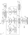
- the controller 80 may perform leak mitigation as illustrated by the flow chart in FIG. 2 .
- the controller 80 is programmed to output for display an indicator.
- the indicator may be an auditory indicator, a visual indicator, or the like.
- the controller 80 may transmit information or data indicative of the leak to a driver, operator, remote computing system, a remote monitoring system, or a display.
- the controller 80 may assess the operational state of various components of the refrigeration system 10, in parallel, substantially simultaneously, or sequentially. At block 210, the controller 80 may assess whether the compressor 20 is on and operational (e.g. running). At block 212, the controller 80 may assess whether the evaporator fan 68 is on and operational (e.g. running). At block 214, the controller 80 may assess the position of the first valve 66.
- the controller 80 may command that the compressor 20 to operate, at block 220. If the compressor is running at block 210, the method 200 may continue to block 230.
- the controller 80 may command that the evaporator fan 68 operate at block 222.
- the operation of the evaporator fan 68 may facilitate the disbursement or dilution of refrigerant proximate the evaporator 24.
- the operation of the evaporator fan 68 may facilitate the releasing or venting of refrigerant from within the interior volume 14 towards an external environment.
- the controller 80 may inhibit the evaporator fan 68 from operating.
- the inhibition of operation of the evaporator fan 68 may prevent refrigerant from being released or vented into an external environment. If the evaporator fan 68 is running at block 212, the method 200 may continue to block 230.
- the controller 80 may command that the first valve 66 move towards the closed position, at block 224.
- the closing of the first valve 66 inhibits a fluid flow of refrigerant between the receiver outlet 74 and the evaporator inlet 60.
- the closing of the first valve 66 essentially inhibits the delivery of refrigerant to the evaporator 24 that may be the source of the refrigerant leak into the interior volume 14. If at least the first valve 66 is in a closed position, the method may contain the block 230.
- the closing of the first valve 66 enables the compressor 20 to evacuate or pump down the evaporator 24 to slow or stop the refrigerant leak into the interior volume 14.
- the compressor 20 is operated while the first valve 66 is closed such that a fluid flow of refrigerant from the evaporator 24 is directed through the evaporator outlet 62 via the refrigerant line 69 towards the compressor inlet 40.
- the removal of refrigerant from the evaporator 24 may be referred to as a pump down of the evaporator 24.
- the compressor 20 directs the fluid flow of refrigerant from the evaporator 24, through the compressor outlet 20, and into the receiver 46 through the condenser inlet 50 and out of the condenser outlet 52 towards the first receiver inlet 70 such that the refrigerant is stored within the receiver 46.
- the closing of the first valve 66 inhibits the refrigerant that is present within the receiver 46 from being delivered to the evaporator 24.
- the compressor 20 may pump down the evaporator 24 and direct the fluid flow of refrigerant from the evaporator 24 through the compressor 20 and towards the condenser 22.
- the flow of refrigerant is directed into the condenser 22 through the condenser inlet 50 and is inhibited from flowing towards the receiver 46 by the second valve 76 being in the closed position.
- the compressor 20 may be provided with an anti-backflow valve such that refrigerant received by the condenser 22 is retained or is received within the condenser 22 and/or between the compressor 20 is unable to flow back through the compressor outlet 42 towards the compressor inlet 40.
- the method 200 may move onto block 230 or 231.
- the method 200 may assess whether there is suction, such as a suction pressure less than an ambient pressure, within the refrigerant line 69 that extends between the evaporator 24 and the compressor 20.
- a pressure sensor 90 is configured to detect pressure within the refrigerant line 69 and communicate the detected pressure to the controller 80.
- the method may alternatively assess a fluid pressure within the evaporator 24 (e.g. evaporator pressure) and determine whether the fluid pressure within the evaporator 24 is less than a threshold pressure.
- the pressure sensor 90 is disposed within or proximate the evaporator 24.
- the method 200 may continue to block 232. If the suction pressure is greater than the ambient pressure or the pressure within the evaporator 24 is greater than a threshold pressure, the method may return to block 210, block 212, and/or block 214.
- the method may move to block 231 if a compressor discharge pressure is utilized rather than a suction pressure.
- a compressor discharge pressure may be utilized if the fourth valve 78 is not present in the refrigeration system 10.
- the method 200 may assess whether there is a discharge pressure at a compressor outlet 42 greater than a selected pressure, within the refrigerant line 56 that extends between the compressor 20 and the condenser 22.
- a compressor discharge pressure sensor 92 is configured to detect pressure within the refrigerant line 56 and communicate the detected pressure to the controller 80. Should the compressor discharge pressure be greater than the selected pressure, the method 200 may continue to block 232. If the compressor discharge pressure is not greater than the selected pressure, the method may return to block 210, block 212, and/or block 214.
- the controller 80 may command the second valve 76 to close such that the refrigerant within the receiver 46 is inhibited from escaping the receiver 46 and flowing toward either the evaporator 24 and/or the condenser 22.
- the refrigeration system 110 is shut down.
- the leak mitigation strategy utilizing the pump down process greatly reduces the risk of the refrigerant reaching the lower flammability limit by removing and storing refrigerant from the evaporator 24 within at least one of the receiver 46 or the condenser 22 outside of the interior volume 14.
- the leak mitigation strategy may also dilute or disperse refrigerant that may be present within the interior volume 14 of the conditioned space 12. If a refrigerant leak is in an area that is not exposed to the interior volume 14 than the refrigerant may dissipate on its own. Additionally, the operation of the condenser fan 58 may facilitate the disbursement or dilution of refrigerant proximate the condenser 22 and may be utilized at any time during the method 200.
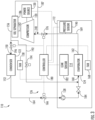
- a refrigeration system 110 having a heat line 192 for hot gas by-pass is illustrated, in accordance with an embodiment of the present invention.
- a conditioned space 112 that provides conditioned air or cooled air to an interior volume 114 of the conditioned space 112 is illustrated in FIG. 3 .
- the conditioned space 112 may include but is not limited to a refrigerated trailer, a refrigerated truck, a refrigerated space, or a refrigerated container.
- the refrigeration system 110 may be adapted to operate using a refrigerant such as a low global warming potential refrigerant including A1, A2, A2L, A3, etc.
- the refrigerant may leak into the interior volume 114 and may present a hazard should the concentration of the leaked refrigerant within the interior volume 114 exceed a threshold level.
- the threshold level may be a lower flammability limit of the refrigerant.
- the evaporator 124, a portion of a refrigerant line 169 proximate an evaporator outlet 162, and a portion of a refrigerant line 164 proximate an evaporator inlet 60 may be located within the interior volume 114 of the conditioned space 112 and thus may be a potential source of a refrigerant leak into the interior volume 114.
- the refrigeration system 110 may be a transport refrigeration system such as a transportation refrigeration unit.
- the refrigeration system 110 includes a compressor 120, a condenser 122, an evaporator 124, and a leak detection system 126 that is arranged to detect and mitigate the presence of refrigerant within an interior volume 114.
- the compressor 120 is powered by or driven by a power source 130.
- the power source 130 may be an internal combustion engine that drives a generator that is arranged to provide power to the compressor 120 and other components of the refrigeration system 110.
- the compressor 120 is arranged to receive refrigerant through a compressor inlet 140 from the evaporator 124.
- the compressor 120 is arranged to discharge refrigerant through a compressor outlet 142 to the condenser 122.
- the condenser 122 is arranged to receive a fluid flow of refrigerant from the compressor 120 through a condenser inlet 150 and is arranged to discharge a fluid flow of refrigerant through a condenser outlet 152 to the evaporator 124.
- the condenser inlet 150 is fluidly connected to the compressor outlet 142 through a refrigerant line 156.
- An oil separator 186 may be located within the refrigerant line 156 between the compressor 120 and the condenser 122 to remove oil from refrigerant leaving the compressor outlet 142 and direct the oil back to rotary components of the compressor 120.
- a fan such as a condenser fan 158 may be associated with the condenser 122.
- the condenser fan 158 is disposed proximate the condenser 122.
- the evaporator 124 is arranged to receive a fluid flow of refrigerant from the condenser 122 through an evaporator inlet 160 and is arranged to discharge a fluid flow of refrigerant to the compressor 120 through an evaporator outlet 162.
- the evaporator inlet 160 is fluidly connected to the condenser outlet 152 through a refrigerant line 164.
- the evaporator outlet 162 is fluidly connected to the compressor inlet 140 through a refrigerant line 169.
- a first valve 166 may be located within the refrigerant line 164 between the condenser 122 and the evaporator 124. In at least one embodiment, the first valve 166 is arranged to selectively facilitate a fluid flow between the condenser outlet 152 and the evaporator inlet 160.
- the first valve 166 may be an expansion valve such as an electronic expansion valve, a movable valve, a solenoid valve, or a thermal expansion valve.
- the first valve 166 is movable between an open position and a closed position to selectively inhibit and facilitate a fluid flow of refrigerant between the evaporator 124 and the condenser 122.
- the open position facilitates a fluid flow of refrigerant between the condenser outlet 152 and the evaporator inlet 160.
- the closed position inhibits a fluid flow of refrigerant between the condenser outlet 152 and the evaporator inlet 160 through the refrigerant line 164.
- a fan such as an evaporator fan 168 may be associated with the evaporator 124.
- the evaporator fan 168 is disposed proximate the evaporator 124.
- a second valve 176 may be located within the refrigerant line 169 between the evaporator 124 and the compressor 120. In at least one embodiment, the second valve 176 is arranged to selectively facilitate a fluid flow between the evaporator outlet 162 and the compressor inlet 140.
- the second valve 176 may be a movable valve, solenoid valve, check valve, a liquid service valve, a thermal expansion valve, or an electronic expansion valve.
- the second valve 176 is movable between an open position and a closed position. The open position facilitates a fluid flow of refrigerant between the evaporator outlet 162 and the compressor inlet 140. The closed position inhibits a fluid flow of refrigerant between the evaporator outlet 162 and the compressor inlet 140.
- first valve 166 and the second valve 176 may be located outside of the conditioned space 112.
- a main heating valve 196 may be located within the refrigerant line 156 between the compressor 120 and the condenser 122. In at least one embodiment, the main heating valve 196 is arranged to selectively facilitate a fluid flow between the compressor outlet 142 and the condenser inlet 150.
- the main heating valve 196 may be a movable valve, a liquid service valve, a thermal expansion valve, or an electronic expansion valve.
- the main heating valve 196 is movable between an open position and a closed position. The open position facilitates a fluid flow of refrigerant between the compressor outlet 142 and the condenser inlet 150. The closed position inhibits a fluid flow of refrigerant between the compressor outlet 142 and the condenser inlet 150.
- a heat line 192 may fluidly connect the compressor 120 and the refrigerant line 164 proximate the evaporator inlet 160. During a heating mode of the refrigeration system 110, the heat line 192 may deliver hot gas from the compressor 120 to the evaporator inlet 160, which may help defrost the evaporator and/or heat up the interior volume 114.
- a hot gas valve 194 may be located within the heat line 192 between the compressor 120 and the evaporator 124. In at least one embodiment, the hot gas valve 194 is arranged to selectively facilitate a fluid flow between the compressor outlet 156 and the evaporator inlet 160.
- the hot gas valve 194 may be a movable valve, a liquid service valve, a thermal expansion valve, or an electronic expansion valve.
- the hot gas valve 194 is movable between an open position and a closed position. The open position facilitates a fluid flow of hot gas refrigerant between the compressor outlet 156 and the evaporator inlet 160.
- the closed position inhibits a fluid flow of hot gas refrigerant between the compressor outlet 156 and the evaporator inlet 160.
- the refrigeration system 110 may include a check valve 128 located within the refrigerant line 164 between the first valve 166 and the evaporator 160, as shown in FIG. 3 .
- the refrigeration system 110 may also include an expansion valve 184 located within the refrigerant line 164 between the check valve 128 and the evaporator 160, as shown in FIG. 3 .
- the refrigeration system 110 may additionally include a pressure sensor 190 located within the refrigerant line 169 interposed between the evaporator 124 and the compressor inlet 140.
- the leak detection system 126 includes a controller 180 and a leak sensor 182.
- the leak sensor 82 may be configured to detect refrigerant, detect a selected concentration of the refrigerant, and/or calculate a concentration of refrigerant.
- the leak sensor 182 may be located within the conditioned space 112.
- the controller 180 may be a controller that is provided with the transport refrigeration unit or may be a separately provided controller.
- the controller 180 is provided with input communication channels that are arranged to receive information, data, or signals from, for example, at least one of the compressor 120, the power source 130, the condenser fan 158, the first valve 166, the evaporator fan 168, the second valve 176, and the leak sensor 182.
- the controller 180 is provided with output communication channels that are arranged to provide commands, signals, or data, for example, to the compressor 120, the power source 130, the condenser fan 158, the first valve 166, the evaporator fan 168, the pressure sensor 190, and the second valve 176.
- the controller 180 is provided with at least one processor that is programmed to execute a leak detection and/or leak mitigation strategy based on information, data, or signals provided via the input communication channels and output commands via the output communication channels.
- the leak sensor 182 is arranged to provide a signal indicative of a concentration, an amount or the presence of refrigerant within the interior volume 114 to the controller 180.
- the leak sensor 182 may be disposed proximate the evaporator 124 and/or may be disposed proximate the refrigerant line 169 or any other refrigerant line or component that could leak refrigerant into the conditioned space 112.
- the leak sensor 182 may also be located near a likely location where refrigerant may collect such as near a floor of the conditioned space 112.
- the controller 180 may perform leak mitigation as illustrated by the flow chart in FIG. 4 .
- a method 300 of leak detection in a refrigeration system 110 is illustrated in accordance with an embodiment of the present invention.
- the method 300 may be performed by the controller 180.
- the method 300 may end and/or continuously check for refrigerant leaks on a recurring basis. If the leak sensor 182 detects the presence of refrigerant or detects the concentration of refrigerant greater than a threshold concentration, the method 300 may continue to block 302.
- the controller 180 may record the leak and the entrance of the leak mitigation strategy into memory.
- the controller 180 is programmed to output for display an indicator.
- the indicator may be an auditory indicator, a visual indicator, or the like.
- the controller 180 may transmit information or data indicative of the leak to a driver, operator, remote computing system, a remote monitoring system, or a display.
- the controller 180 may assess the operational state of various components of the refrigeration system 110, in parallel, substantially simultaneously, or sequentially. At block 342, the controller 180 may assess whether the main heating valve 196 is open. At block 342, if the main heating valve 196 is not open then the controller 180 will open the main heating valve 196 at block 354. At block 344, the controller 180 may assess whether the hot gas valve 194 is open. At block 344, if the hot gas valve 194 is open then the controller 180 will close the hot gas valve 194 at block 356. At block 346, the controller 180 may assess whether the condenser fan 158 is on and operation (e.g., running).
- the controller 180 may command the condenser fan 158 to run at block 358.
- the operation of the condenser fan 158 may facilitate the disbursement or dilution of refrigerant proximate the condenser 122 if a leak occurs on a condenser side of the refrigeration system 110.
- the controller 180 may assess whether the evaporator fan 168 is on and in operation (e.g., running).
- the controller 180 may command the evaporator fan 168 to run at block 360.
- the operation of the evaporator fan 168 may facilitate the disbursement or dilution of refrigerant proximate the evaporator 124.
- the controller 180 may assess whether the first valve 166 is open. At block 350, if the first valve 166 is open then the controller 180 will close the first valve 166 at block 362. At block 352, the controller 180 may assess whether the second valve 176 is open. At block 352, if the second valve 176 is closed then the controller 180 will open the second valve 176 at block 364.
- the controller 180 may assess whether the compressor 120 is on and operational (e.g. running). At block 366, if the compressor 180 is not on and operational then the controller 180 will run the compressor 180 before moving onto block 370. At block 370, the controller 180 may assess whether there is a suction pressure, such as a suction pressure less than an ambient pressure, within the refrigerant line 169 that extends between the evaporator 124 and the compressor 120. In such an embodiment, a pressure sensor 190 is configured to detect pressure within the refrigerant line 169 and communicate the detected pressure to the controller 180. At block 370, the method may alternatively assess a fluid pressure within the evaporator 124 (e.g.
- the method 300 may continue to block 372. If the suction pressure is greater than the ambient pressure or the pressure within the evaporator 124 is greater than a threshold pressure, the method 300 may return to block 366.
- the controller 180 may assess whether the second valve 176 is open. At block 372, if the second valve 176 is open then the controller 180 will close the second valve 176 at block 374 before moving onto block 376. At block 376, the refrigeration system 110 is shut down.
- the leak mitigation strategy utilizing the pump down process greatly reduces the risk of the refrigerant reaching the lower flammability limit by removing and storing refrigerant from the evaporator 124 within the condenser 122.
- the leak mitigation strategy may also dilute or disperse refrigerant that may be present within the interior volume 114 of the conditioned space 112. If a refrigerant leak is in an area that is not exposed to the interior volume 114 than the refrigerant may dissipate on its own or with the aid of a condenser fan.
Landscapes
- Engineering & Computer Science (AREA)
- Physics & Mathematics (AREA)
- Thermal Sciences (AREA)
- Mechanical Engineering (AREA)
- General Engineering & Computer Science (AREA)
- Air Conditioning Control Device (AREA)
- Devices That Are Associated With Refrigeration Equipment (AREA)
Description
- The invention pertains to the art of refrigerated systems. More specifically, transportation refrigeration units.
- Products may be shipped or stored within a conditioned space, such as a container, truck or trailer. These conditioned spaces utilize a refrigeration unit that circulates cooled air inside the interior volume. In many cases, the refrigeration unit uses a refrigeration cycle to cool the air. Refrigerant from the refrigeration unit may leak inside the conditioned space.
-
EP 3 358 278 A1 discloses a refrigeration system according to the preamble of claim 1 having a plurality of conditioned spaces each having a refrigerant leakage sensor, wherein the supply of refrigerant to each conditioned space can be individually controlled and, in the event of a detected leak, cut off. - According to the invention a refrigeration system according to claim 1 is provided. The refrigeration system includes a compressor, a condenser, an evaporator, a leak sensor, and a controller. The compressor is driven by a power source and has a compressor outlet and a compressor inlet. The condenser has a condenser inlet fluidly connected to the compressor outlet and a condenser outlet. The evaporator has an evaporator inlet fluidly connected to the condenser outlet through a first valve movable between an open position and a closed position, and an evaporator outlet fluidly connected to the compressor inlet. The leak sensor is arranged to provide a signal indicative of a refrigerant. The controller is in communication with the first valve and the compressor. The controller is arranged to receive the signal and is programmed to command the first valve to move towards the closed position, responsive to the signal being indicative of the refrigerant. The refrigeration system includes a second valve fluidly connecting the evaporator outlet and the compressor inlet, the second valve being movable between an open position and a closed position. The controller is further programmed to operate the compressor such that refrigerant within the evaporator is directed towards the compressor until a suction pressure measurement proximate an inlet of the compressor is less than an ambient pressure. The controller is further programmed to command the second valve to move towards the closed position when the suction pressure measurement proximate an inlet of the compressor is less than an ambient pressure.
- In addition to one or more of the features described above, or as an alternative, further embodiments may include that the controller is further programmed to output for display an indicator.
- In addition to one or more of the features described above, or as an alternative, further embodiments may include that the controller is further programmed to operate the compressor such that refrigerant within the evaporator is directed towards the compressor.
- In addition to one or more of the features described above, or as an alternative, further embodiments may include that the controller is further programmed to command the compressor to stop operating, responsive to a fluid pressure between the evaporator outlet and the compressor outlet being less than a threshold pressure.
- In addition to one or more of the features described above, or as an alternative, further embodiments may include a receiver having a receiver inlet fluidly connected to the condenser outlet, wherein the receiver is arranged to receive the refrigerant from the condenser.
- In addition to one or more of the features described above, or as an alternative, further embodiments may include that the controller is arranged to receive the signal and programmed to command the first valve to move towards the closed position, responsive to the signal being indicative of a selected concentration of the refrigerant.
- In addition to one or more of the features described above, or as an alternative, further embodiments may include that the controller is further programmed to operate an evaporator fan when refrigerant is detected.
- In addition to one or more of the features described above, or as an alternative, further embodiments may include a main heat valve fluidly connecting the compressor outlet and the condenser inlet, the main heat valve being movable between an open position and a closed position, wherein the controller is programed to command the main heat valve to move to the open position.
- In addition to one or more of the features described above, or as an alternative, further embodiments may include a hot gas valve fluidly connecting the compressor and the evaporator inlet, the hot gas valve being movable between an open position and a closed position, and wherein the controller is programed to command the hot gas valve to move to the closed position prior to commanding the first valve to move towards the closed position.
- In addition to one or more of the features described above, or as an alternative, further embodiments may include that the evaporator and the leak sensor are located within a conditioned space of the refrigeration system, and wherein the first valve and the second valve are located outside of the conditioned space.
- According to the invention a method of mitigating refrigerant leaks within a refrigeration system according to claim 10 is provided. The method includes: detecting a leak of a refrigerant from a refrigeration system; closing a first valve to inhibit a fluid flow of the refrigerant between an evaporator and a condenser fluidly connected to the evaporator; operating a compressor to direct another fluid flow of the refrigerant from the evaporator to the compressor; operating the compressor to direct another fluid flow of the refrigerant from the evaporator to the compressor until a suction pressure measurement proximate an inlet of the compressor is less than an ambient pressure; and closing a second valve when the suction pressure measurement proximate an inlet of the compressor is less than an ambient pressure, the second valve fluidly connecting the evaporator outlet and the compressor inlet.
- In addition to one or more of the features described above, or as an alternative, further embodiments may include directing the fluid flow of the refrigerant from the compressor to a receiver.
- In addition to one or more of the features described above, or as an alternative, further embodiments may include operating an evaporator fan that is disposed proximate the evaporator.
- In addition to one or more of the features described above, or as an alternative, further embodiments may include stopping operation of the compressor, responsive to an evaporator pressure being less than a threshold pressure.
- In addition to one or more of the features described above, or as an alternative, further embodiments may include closing a second valve to inhibit a fluid flow of the refrigerant between the receiver and the condenser.
- According to the invention the refrigeration system and the method includes closing a second valve to inhibit a fluid flow of the refrigerant between the evaporator and the compressor.
- In addition to one or more of the features described above, or as an alternative, further embodiments may include that the method further includes: opening a main heat valve to allow a fluid flow of the refrigerant between the compressor and the condenser; and closing a hot gas valve to inhibit a fluid flow of the refrigerant between the compressor and the evaporator.
- The following descriptions should not be considered limiting in any way. With reference to the accompanying drawings, like elements are numbered alike:
-
FIG. 1 is a schematic illustration of a refrigeration system; -
FIG. 2 is a flowchart illustrating a method of refrigerant leak mitigation for a refrigeration system -
FIG. 3 is a schematic illustration of a refrigeration system; -
FIG. 4 is a flowchart illustrating a method of refrigerant leak mitigation for a refrigeration system; and -
FIG. 5 is a perspective view of a transport system having a refrigeration system as one, non-limiting, according to an embodiment of the present invention. - A detailed description of one or more embodiments of the disclosed apparatus and method are presented herein by way of exemplification and not limitation with reference to the Figures.
- Referring to
FIG. 5 , atransport system 420 is illustrated. In the illustrated embodiment, thetransport systems 420 may include a tractor orvehicle 422, a conditionedspace space vehicle 422. It is understood that embodiments described herein may be applied to conditioned space that are shipped by rail, sea, air, or any other suitable container, thus the vehicle may be a truck, train, boat, airplane, helicopter, etc. - The
vehicle 422 may include an operator's compartment orcab 428 and avehicle motor 442. Thevehicle 22 may be driven by a driver located within the cab, driven by a driver remotely, driven autonomously, driven semi-autonomously, or any combination thereof. Thevehicle motor 442 may be an electric or combustion engine powered by a combustible fuel. Thevehicle motor 442 may also be part of the power train or drive system of the trailer system (i.e., conditionedspace 12, 112), thus thevehicle motor 442 is configured to propel the wheels of thevehicle 22 and/or the wheels of the conditionedspace vehicle motor 442 may be mechanically connected to the wheels of thevehicle 422 and/or the wheels of the conditionedspace - The conditioned
space vehicle 22 and is thus pulled or propelled to desired destinations. The conditionedspace top wall 430, abottom wall 432 opposed to and spaced from thetop wall 430, twoside walls 434 spaced from and opposed to one-another, and opposing front andrear walls front wall 436 being closest to thevehicle 422. The conditionedspace rear wall 438, or any other wall. Thewalls interior volume transport systems 420 are used to transport and distribute cargo, such as, for example perishable goods and environmentally sensitive goods (herein referred to as perishable goods). The perishable goods may include but are not limited to fruits, vegetables, grains, beans, nuts, eggs, dairy, seed, flowers, meat, poultry, fish, ice, blood, pharmaceuticals, or any other suitable cargo requiring cold chain transport. In the illustrated embodiment, the refrigeration system 10, 100 is associated with a conditionedspace interior volume - Referring to
FIG. 1 , a conditionedspace 12 may be provided with a refrigeration system 10 that provides conditioned air or cooled air to aninterior volume 14 of the conditionedspace 12. The conditionedspace 12 may include but is not limited to a refrigerated trailer, a refrigerated truck, a refrigerated space, or a refrigerated container. The refrigeration system 10 may be adapted to operate using a refrigerant such as a low global warming potential refrigerant including A1, A2, A2L, A3, etc. In some cases, the refrigerant may leak into theinterior volume 14 and may present a hazard should the concentration of the leaked refrigerant within theinterior volume 14 exceed a threshold level. The threshold level may be a lower flammability limit of the refrigerant. Theevaporator 24, a portion of arefrigerant line 69 proximate anevaporator outlet 62, and a portion of a refrigerant line 64a proximate anevaporator inlet 60 may be located within theinterior volume 14 of the conditionedspace 12 and thus may be a potential source of a refrigerant leak into theinterior volume 14. - The refrigeration system 10 may be a transport refrigeration system such as a transportation refrigeration unit. The refrigeration system 10 includes a
compressor 20, acondenser 22, anevaporator 24, and aleak detection system 26 that is arranged to detect and mitigate the presence of refrigerant within aninterior volume 14. - The
compressor 20 is powered by or driven by apower source 30. Thepower source 30 may be an internal combustion engine that drives a generator that is arranged to provide power to the compressor through a belt or otherwise provide power to thecompressor 20 and other components of the refrigeration system 10. - The
compressor 20 is arranged to receive refrigerant through acompressor inlet 40 from theevaporator 24. Thecompressor 20 is arranged to discharge refrigerant through acompressor outlet 42 to thecondenser 22 through areceiver 46. - The
condenser 22 is arranged to receive a fluid flow of refrigerant from thecompressor 20 through a condenser inlet 50 and is arranged to discharge a fluid flow of refrigerant through acondenser outlet 52 to thereceiver 46. The condenser inlet 50 is fluidly connected to thecompressor outlet 42 through arefrigerant line 56. - A fan such as a
condenser fan 58 may be associated with thecondenser 22. Thecondenser fan 58 is disposed proximate thecondenser 22. - The
evaporator 24 is arranged to receive a fluid flow of refrigerant from thecondenser 22 through anevaporator inlet 60 and is arranged to discharge a fluid flow of refrigerant to thecompressor 20 through anevaporator outlet 62. Theevaporator inlet 60 is fluidly connected to thecondenser outlet 52 through thereceiver 46 via a refrigerant line 64a, b through afirst valve 66 and/or asecond valve 76 that is disposed on an opposite side of thereceiver 46 than thefirst valve 66. Theevaporator outlet 62 is fluidly connected to thecompressor inlet 40 through arefrigerant line 69. - The
first valve 66 may be an expansion valve such as an electronic expansion valve, a movable valve, or a thermal expansion valve. Thefirst valve 66 is movable between an open position and a closed position to selectively inhibit and facilitate a fluid flow of refrigerant between the evaporator 24 and at least one of thecondenser 22 and thereceiver 46. The open position facilitates a fluid flow of refrigerant between theevaporator inlet 60 and thecondenser outlet 52 through thereceiver 46. The closed position inhibits a fluid flow of refrigerant between theevaporator inlet 60 and thecondenser outlet 52 through thereceiver 46 as well as inhibits a fluid flow of refrigerant between thereceiver 46 and theevaporator inlet 60. - A fan such as an
evaporator fan 68 may be associated with theevaporator 24. Theevaporator fan 68 is disposed proximate theevaporator 24. - The
receiver 46 is fluidly connected to thecondenser 22 and theevaporator 24 and is arranged to receive and store refrigerant based on a position of at least one of thefirst valve 66 and/or thesecond valve 76. Thereceiver 46 is arranged to receive refrigerant from thecondenser outlet 52 through afirst receiver inlet 70 via therefrigerant line 64b. In at least one embodiment, thesecond valve 76 is arranged to selectively facilitate a fluid flow between thecondenser outlet 52 and thefirst receiver inlet 70. Thesecond valve 76 may be a movable valve, a solenoid valve, a liquid service valve, a thermal expansion valve, or an electronic expansion valve. Thesecond valve 76 is movable between an open position and a closed position. The open position facilitates a fluid flow of refrigerant between thecondenser outlet 52 and thefirst receiver inlet 70. The closed position inhibits a fluid flow of refrigerant between thecondenser outlet 52 and thefirst receiver inlet 70. Thereceiver 46 is arranged to discharge or provide a fluid flow of refrigerant through areceiver outlet 74 to theevaporator inlet 60 via thefirst valve 66 through the refrigerant line 64a. - A
third valve 77 may be arranged to selectively facilitate a fluid flow between thecompressor outlet 42 and the condenser inlet 50. Thethird valve 77 may be a movable valve, check valve, a liquid service valve, a thermal expansion valve, or an electronic expansion valve. Thethird valve 77 is movable between an open position and a closed position. The open position facilitates a fluid flow of refrigerant between thecompressor outlet 42 and the condenser inlet 50. The closed position inhibits a fluid flow of refrigerant between thecompressor outlet 42 and the condenser inlet 50. Alternatively, thethird valve 77 may be interposed inrefrigerant line 69. - A fourth valve 78 may be arranged to selectively facilitate a fluid flow between the
evaporator outlet 62 and thecompressor inlet 40. The fourth valve 78 may be a movable valve, check valve, a liquid service valve, a thermal expansion valve, or an electronic expansion valve. The fourth valve 78 is movable between an open position and a closed position. The open position facilitates a fluid flow of refrigerant between theevaporator outlet 62 and thecompressor inlet 40. The closed position inhibits a fluid flow of refrigerant between theevaporator outlet 62 and thecompressor inlet 40. - In an embodiment, the
first valve 66, thesecond valve 76, thethird valve 77, and the fourth valve 78 may be located outside of the conditionedspace 12. - As stated previously, the open position of the
first valve 66 facilitates a fluid flow of refrigerant between thereceiver outlet 74 and theevaporator inlet 60. The closed position of thefirst valve 66 inhibits a fluid flow of refrigerant between thereceiver outlet 74 and theevaporator inlet 60. - The
leak detection system 26 includes acontroller 80 and aleak sensor 82. Theleak sensor 82 may be configured to detect refrigerant, detect a selected concentration of the refrigerant, and/or calculate a concentration of refrigerant. Thecontroller 80 may be a controller that is provided with the transport refrigeration unit or may be a separately provided controller. - The
controller 80 is provided with input communication channels that are arranged to receive information, data, or signals from, for example, thecompressor 20, thepower source 30, thecondenser fan 58, thefirst valve 66, theevaporator fan 68, thesecond valve 76, apressure sensor 90, a compressordischarge pressure sensor 92, and theleak sensor 82. Thecontroller 80 is provided with output communication channels that are arranged to provide commands, signals, or data to, for example, thecompressor 20, thepower source 30, thecondenser fan 58, thefirst valve 66, theevaporator fan 68, and thesecond valve 76. Thecontroller 80 is provided with at least one processor that is programmed to execute a leak detection and/or leak mitigation strategy based on information, data, or signals provided via the input communication channels and output commands via the output communication channels. - The
leak sensor 82 is arranged to provide a signal indicative of a concentration, an amount, or the presence of refrigerant within theinterior volume 14 to thecontroller 80. Theleak sensor 82 may be disposed proximate theevaporator 24 and/or may be disposed proximate therefrigerant line 69 or any other refrigerant line or component that could leak refrigerant into the conditionedspace 12. Theleak sensor 82 may also be located near a likely location where refrigerant may collect, such as near a floor of thecontainer 12. - Responsive to the signal from the
leak sensor 82 being indicative of a concentration of refrigerant greater than a threshold concentration or the signal being indicative of the presence of refrigerant within theinterior volume 14, thecontroller 80 may perform leak mitigation as illustrated by the flow chart inFIG. 2 . - Referring to
FIG. 2 , with continued references toFIG. 1 , amethod 200 of leak detection in a refrigeration system 10 is illustrated in accordance with an embodiment of the present invention. In an embodiment, themethod 200 may be performed by thecontroller 80. Atblock 201, should theleak sensor 82 not detect the presence of refrigerant or the concentration of refrigerant greater than a threshold concentration, the method may end and/or continuously check for refrigerant leaks on a recurring basis. If theleak sensor 82 detects the presence of refrigerant or detects the concentration of refrigerant greater than a threshold concentration, themethod 200 may continue to block 202. Atblock 202, thecontroller 80 may record the leak and the entrance of the leak mitigation strategy into memory. Atblock 204, thecontroller 80 is programmed to output for display an indicator. The indicator may be an auditory indicator, a visual indicator, or the like. In at least one embodiment, thecontroller 80 may transmit information or data indicative of the leak to a driver, operator, remote computing system, a remote monitoring system, or a display. - The
controller 80 may assess the operational state of various components of the refrigeration system 10, in parallel, substantially simultaneously, or sequentially. Atblock 210, thecontroller 80 may assess whether thecompressor 20 is on and operational (e.g. running). Atblock 212, thecontroller 80 may assess whether theevaporator fan 68 is on and operational (e.g. running). Atblock 214, thecontroller 80 may assess the position of thefirst valve 66. - Should the
compressor 20 not be running atblock 210, thecontroller 80 may command that thecompressor 20 to operate, atblock 220. If the compressor is running atblock 210, themethod 200 may continue to block 230. - Should the
evaporator fan 68 not be running atblock 212, thecontroller 80 may command that theevaporator fan 68 operate atblock 222. The operation of theevaporator fan 68 may facilitate the disbursement or dilution of refrigerant proximate theevaporator 24. The operation of theevaporator fan 68 may facilitate the releasing or venting of refrigerant from within theinterior volume 14 towards an external environment. In at least one embodiment, should theevaporator fan 68 not be running atblock 212, thecontroller 80 may inhibit theevaporator fan 68 from operating. The inhibition of operation of theevaporator fan 68 may prevent refrigerant from being released or vented into an external environment. If theevaporator fan 68 is running atblock 212, themethod 200 may continue to block 230. - Should the
first valve 66 be open atblock 214, thecontroller 80 may command that thefirst valve 66 move towards the closed position, atblock 224. The closing of thefirst valve 66 inhibits a fluid flow of refrigerant between thereceiver outlet 74 and theevaporator inlet 60. The closing of thefirst valve 66 essentially inhibits the delivery of refrigerant to theevaporator 24 that may be the source of the refrigerant leak into theinterior volume 14. If at least thefirst valve 66 is in a closed position, the method may contain theblock 230. - The closing of the
first valve 66 enables thecompressor 20 to evacuate or pump down theevaporator 24 to slow or stop the refrigerant leak into theinterior volume 14. Thecompressor 20 is operated while thefirst valve 66 is closed such that a fluid flow of refrigerant from theevaporator 24 is directed through theevaporator outlet 62 via therefrigerant line 69 towards thecompressor inlet 40. The removal of refrigerant from theevaporator 24 may be referred to as a pump down of theevaporator 24. Thecompressor 20 directs the fluid flow of refrigerant from theevaporator 24, through thecompressor outlet 20, and into thereceiver 46 through the condenser inlet 50 and out of thecondenser outlet 52 towards thefirst receiver inlet 70 such that the refrigerant is stored within thereceiver 46. The closing of thefirst valve 66 inhibits the refrigerant that is present within thereceiver 46 from being delivered to theevaporator 24. In at least one embodiment, should thesecond valve 76 be closed, thecompressor 20 may pump down theevaporator 24 and direct the fluid flow of refrigerant from theevaporator 24 through thecompressor 20 and towards thecondenser 22. The flow of refrigerant is directed into thecondenser 22 through the condenser inlet 50 and is inhibited from flowing towards thereceiver 46 by thesecond valve 76 being in the closed position. Thecompressor 20 may be provided with an anti-backflow valve such that refrigerant received by thecondenser 22 is retained or is received within thecondenser 22 and/or between thecompressor 20 is unable to flow back through thecompressor outlet 42 towards thecompressor inlet 40. - The
method 200 may move ontoblock block 230, themethod 200 may assess whether there is suction, such as a suction pressure less than an ambient pressure, within therefrigerant line 69 that extends between the evaporator 24 and thecompressor 20. In such an embodiment, apressure sensor 90 is configured to detect pressure within therefrigerant line 69 and communicate the detected pressure to thecontroller 80. Atblock 230, the method may alternatively assess a fluid pressure within the evaporator 24 (e.g. evaporator pressure) and determine whether the fluid pressure within theevaporator 24 is less than a threshold pressure. In such an embodiment, thepressure sensor 90 is disposed within or proximate theevaporator 24. Should the suction pressure be less than the ambient pressure or the evaporator pressure be less than a threshold pressure, themethod 200 may continue to block 232. If the suction pressure is greater than the ambient pressure or the pressure within theevaporator 24 is greater than a threshold pressure, the method may return to block 210, block 212, and/or block 214. - Alternatively, the method may move to block 231 if a compressor discharge pressure is utilized rather than a suction pressure. For example, a compressor discharge pressure may be utilized if the fourth valve 78 is not present in the refrigeration system 10. At
block 231, themethod 200 may assess whether there is a discharge pressure at acompressor outlet 42 greater than a selected pressure, within therefrigerant line 56 that extends between thecompressor 20 and thecondenser 22. In such an embodiment, a compressordischarge pressure sensor 92 is configured to detect pressure within therefrigerant line 56 and communicate the detected pressure to thecontroller 80. Should the compressor discharge pressure be greater than the selected pressure, themethod 200 may continue to block 232. If the compressor discharge pressure is not greater than the selected pressure, the method may return to block 210, block 212, and/or block 214. - At
block 232, should thesecond valve 76 be in an open position, thecontroller 80 may command thesecond valve 76 to close such that the refrigerant within thereceiver 46 is inhibited from escaping thereceiver 46 and flowing toward either theevaporator 24 and/or thecondenser 22. At block 334, therefrigeration system 110 is shut down. - The leak mitigation strategy utilizing the pump down process greatly reduces the risk of the refrigerant reaching the lower flammability limit by removing and storing refrigerant from the
evaporator 24 within at least one of thereceiver 46 or thecondenser 22 outside of theinterior volume 14. The leak mitigation strategy may also dilute or disperse refrigerant that may be present within theinterior volume 14 of the conditionedspace 12. If a refrigerant leak is in an area that is not exposed to theinterior volume 14 than the refrigerant may dissipate on its own. Additionally, the operation of thecondenser fan 58 may facilitate the disbursement or dilution of refrigerant proximate thecondenser 22 and may be utilized at any time during themethod 200. - Referring to
FIG. 3 , arefrigeration system 110 having aheat line 192 for hot gas by-pass is illustrated, in accordance with an embodiment of the present invention. A conditionedspace 112 that provides conditioned air or cooled air to aninterior volume 114 of the conditionedspace 112 is illustrated inFIG. 3 . The conditionedspace 112 may include but is not limited to a refrigerated trailer, a refrigerated truck, a refrigerated space, or a refrigerated container. Therefrigeration system 110 may be adapted to operate using a refrigerant such as a low global warming potential refrigerant including A1, A2, A2L, A3, etc. In some case the refrigerant may leak into theinterior volume 114 and may present a hazard should the concentration of the leaked refrigerant within theinterior volume 114 exceed a threshold level. The threshold level may be a lower flammability limit of the refrigerant. Theevaporator 124, a portion of arefrigerant line 169 proximate anevaporator outlet 162, and a portion of arefrigerant line 164 proximate anevaporator inlet 60 may be located within theinterior volume 114 of the conditionedspace 112 and thus may be a potential source of a refrigerant leak into theinterior volume 114. - The
refrigeration system 110 may be a transport refrigeration system such as a transportation refrigeration unit. Therefrigeration system 110 includes acompressor 120, acondenser 122, anevaporator 124, and aleak detection system 126 that is arranged to detect and mitigate the presence of refrigerant within aninterior volume 114. - The
compressor 120 is powered by or driven by apower source 130. Thepower source 130 may be an internal combustion engine that drives a generator that is arranged to provide power to thecompressor 120 and other components of therefrigeration system 110. - The
compressor 120 is arranged to receive refrigerant through acompressor inlet 140 from theevaporator 124. Thecompressor 120 is arranged to discharge refrigerant through acompressor outlet 142 to thecondenser 122. - The
condenser 122 is arranged to receive a fluid flow of refrigerant from thecompressor 120 through acondenser inlet 150 and is arranged to discharge a fluid flow of refrigerant through acondenser outlet 152 to theevaporator 124. Thecondenser inlet 150 is fluidly connected to thecompressor outlet 142 through arefrigerant line 156. - An
oil separator 186 may be located within therefrigerant line 156 between thecompressor 120 and thecondenser 122 to remove oil from refrigerant leaving thecompressor outlet 142 and direct the oil back to rotary components of thecompressor 120. - A fan such as a
condenser fan 158 may be associated with thecondenser 122. Thecondenser fan 158 is disposed proximate thecondenser 122. - The
evaporator 124 is arranged to receive a fluid flow of refrigerant from thecondenser 122 through anevaporator inlet 160 and is arranged to discharge a fluid flow of refrigerant to thecompressor 120 through anevaporator outlet 162. Theevaporator inlet 160 is fluidly connected to thecondenser outlet 152 through arefrigerant line 164. Theevaporator outlet 162 is fluidly connected to thecompressor inlet 140 through arefrigerant line 169. - A
first valve 166 may be located within therefrigerant line 164 between thecondenser 122 and theevaporator 124. In at least one embodiment, thefirst valve 166 is arranged to selectively facilitate a fluid flow between thecondenser outlet 152 and theevaporator inlet 160. Thefirst valve 166 may be an expansion valve such as an electronic expansion valve, a movable valve, a solenoid valve, or a thermal expansion valve. Thefirst valve 166 is movable between an open position and a closed position to selectively inhibit and facilitate a fluid flow of refrigerant between theevaporator 124 and thecondenser 122. The open position facilitates a fluid flow of refrigerant between thecondenser outlet 152 and theevaporator inlet 160. The closed position inhibits a fluid flow of refrigerant between thecondenser outlet 152 and theevaporator inlet 160 through therefrigerant line 164. - A fan such as an
evaporator fan 168 may be associated with theevaporator 124. Theevaporator fan 168 is disposed proximate theevaporator 124. - A
second valve 176 may be located within therefrigerant line 169 between theevaporator 124 and thecompressor 120. In at least one embodiment, thesecond valve 176 is arranged to selectively facilitate a fluid flow between theevaporator outlet 162 and thecompressor inlet 140. Thesecond valve 176 may be a movable valve, solenoid valve, check valve, a liquid service valve, a thermal expansion valve, or an electronic expansion valve. Thesecond valve 176 is movable between an open position and a closed position. The open position facilitates a fluid flow of refrigerant between theevaporator outlet 162 and thecompressor inlet 140. The closed position inhibits a fluid flow of refrigerant between theevaporator outlet 162 and thecompressor inlet 140. - In an embodiment, the
first valve 166 and thesecond valve 176 may be located outside of the conditionedspace 112. - A
main heating valve 196 may be located within therefrigerant line 156 between thecompressor 120 and thecondenser 122. In at least one embodiment, themain heating valve 196 is arranged to selectively facilitate a fluid flow between thecompressor outlet 142 and thecondenser inlet 150. Themain heating valve 196 may be a movable valve, a liquid service valve, a thermal expansion valve, or an electronic expansion valve. Themain heating valve 196 is movable between an open position and a closed position. The open position facilitates a fluid flow of refrigerant between thecompressor outlet 142 and thecondenser inlet 150. The closed position inhibits a fluid flow of refrigerant between thecompressor outlet 142 and thecondenser inlet 150. - A
heat line 192 may fluidly connect thecompressor 120 and therefrigerant line 164 proximate theevaporator inlet 160. During a heating mode of therefrigeration system 110, theheat line 192 may deliver hot gas from thecompressor 120 to theevaporator inlet 160, which may help defrost the evaporator and/or heat up theinterior volume 114. - A
hot gas valve 194 may be located within theheat line 192 between thecompressor 120 and theevaporator 124. In at least one embodiment, thehot gas valve 194 is arranged to selectively facilitate a fluid flow between thecompressor outlet 156 and theevaporator inlet 160. Thehot gas valve 194 may be a movable valve, a liquid service valve, a thermal expansion valve, or an electronic expansion valve. Thehot gas valve 194 is movable between an open position and a closed position. The open position facilitates a fluid flow of hot gas refrigerant between thecompressor outlet 156 and theevaporator inlet 160. The closed position inhibits a fluid flow of hot gas refrigerant between thecompressor outlet 156 and theevaporator inlet 160. - The
refrigeration system 110 may include acheck valve 128 located within therefrigerant line 164 between thefirst valve 166 and theevaporator 160, as shown inFIG. 3 . Therefrigeration system 110 may also include anexpansion valve 184 located within therefrigerant line 164 between thecheck valve 128 and theevaporator 160, as shown inFIG. 3 . Therefrigeration system 110 may additionally include apressure sensor 190 located within therefrigerant line 169 interposed between theevaporator 124 and thecompressor inlet 140. - The
leak detection system 126 includes acontroller 180 and aleak sensor 182. Theleak sensor 82 may be configured to detect refrigerant, detect a selected concentration of the refrigerant, and/or calculate a concentration of refrigerant. Theleak sensor 182 may be located within the conditionedspace 112. Thecontroller 180 may be a controller that is provided with the transport refrigeration unit or may be a separately provided controller. - The
controller 180 is provided with input communication channels that are arranged to receive information, data, or signals from, for example, at least one of thecompressor 120, thepower source 130, thecondenser fan 158, thefirst valve 166, theevaporator fan 168, thesecond valve 176, and theleak sensor 182. Thecontroller 180 is provided with output communication channels that are arranged to provide commands, signals, or data, for example, to thecompressor 120, thepower source 130, thecondenser fan 158, thefirst valve 166, theevaporator fan 168, thepressure sensor 190, and thesecond valve 176. Thecontroller 180 is provided with at least one processor that is programmed to execute a leak detection and/or leak mitigation strategy based on information, data, or signals provided via the input communication channels and output commands via the output communication channels. - The
leak sensor 182 is arranged to provide a signal indicative of a concentration, an amount or the presence of refrigerant within theinterior volume 114 to thecontroller 180. Theleak sensor 182 may be disposed proximate theevaporator 124 and/or may be disposed proximate therefrigerant line 169 or any other refrigerant line or component that could leak refrigerant into the conditionedspace 112. Theleak sensor 182 may also be located near a likely location where refrigerant may collect such as near a floor of the conditionedspace 112. - Responsive to the signal from the
leak sensor 182 being indicative of a concentration of refrigerant greater than a threshold concentration or the signal being indicative of the presence of refrigerant within theinterior volume 114, thecontroller 180 may perform leak mitigation as illustrated by the flow chart inFIG. 4 . - Referring to
FIG. 4 , with continued references toFIG. 3 , amethod 300 of leak detection in arefrigeration system 110 is illustrated in accordance with an embodiment of the present invention. In an embodiment, themethod 300 may be performed by thecontroller 180. Atblock 301, should theleak sensor 182 not detect the presence of refrigerant or the concentration of refrigerant greater than a threshold concentration, themethod 300 may end and/or continuously check for refrigerant leaks on a recurring basis. If theleak sensor 182 detects the presence of refrigerant or detects the concentration of refrigerant greater than a threshold concentration, themethod 300 may continue to block 302. Atblock 302, thecontroller 180 may record the leak and the entrance of the leak mitigation strategy into memory. Atblock 304, thecontroller 180 is programmed to output for display an indicator. The indicator may be an auditory indicator, a visual indicator, or the like. In at least one embodiment, thecontroller 180 may transmit information or data indicative of the leak to a driver, operator, remote computing system, a remote monitoring system, or a display. - The
controller 180 may assess the operational state of various components of therefrigeration system 110, in parallel, substantially simultaneously, or sequentially. Atblock 342, thecontroller 180 may assess whether themain heating valve 196 is open. Atblock 342, if themain heating valve 196 is not open then thecontroller 180 will open themain heating valve 196 atblock 354. Atblock 344, thecontroller 180 may assess whether thehot gas valve 194 is open. Atblock 344, if thehot gas valve 194 is open then thecontroller 180 will close thehot gas valve 194 atblock 356. Atblock 346, thecontroller 180 may assess whether thecondenser fan 158 is on and operation (e.g., running). Atblock 346, if thecondenser fan 158 is not running then thecontroller 180 may command thecondenser fan 158 to run atblock 358. The operation of thecondenser fan 158 may facilitate the disbursement or dilution of refrigerant proximate thecondenser 122 if a leak occurs on a condenser side of therefrigeration system 110. Atblock 348, thecontroller 180 may assess whether theevaporator fan 168 is on and in operation (e.g., running). Atblock 348, if theevaporator fan 168 is not running then thecontroller 180 may command theevaporator fan 168 to run atblock 360. The operation of theevaporator fan 168 may facilitate the disbursement or dilution of refrigerant proximate theevaporator 124. Atblock 350, thecontroller 180 may assess whether thefirst valve 166 is open. Atblock 350, if thefirst valve 166 is open then thecontroller 180 will close thefirst valve 166 atblock 362. Atblock 352, thecontroller 180 may assess whether thesecond valve 176 is open. Atblock 352, if thesecond valve 176 is closed then thecontroller 180 will open thesecond valve 176 atblock 364. - At
block 366, thecontroller 180 may assess whether thecompressor 120 is on and operational (e.g. running). Atblock 366, if thecompressor 180 is not on and operational then thecontroller 180 will run thecompressor 180 before moving ontoblock 370. Atblock 370, thecontroller 180 may assess whether there is a suction pressure, such as a suction pressure less than an ambient pressure, within therefrigerant line 169 that extends between theevaporator 124 and thecompressor 120. In such an embodiment, apressure sensor 190 is configured to detect pressure within therefrigerant line 169 and communicate the detected pressure to thecontroller 180. Atblock 370, the method may alternatively assess a fluid pressure within the evaporator 124 (e.g. evaporator pressure) and determine whether the fluid pressure within theevaporator 124 is less than a threshold pressure. In such an embodiment, thepressure sensor 190 is disposed within or proximate theevaporator 124. Should the suction pressure be less than the ambient pressure or the evaporator pressure be less than a threshold pressure, themethod 300 may continue to block 372. If the suction pressure is greater than the ambient pressure or the pressure within theevaporator 124 is greater than a threshold pressure, themethod 300 may return to block 366. - At
block 372, thecontroller 180 may assess whether thesecond valve 176 is open. Atblock 372, if thesecond valve 176 is open then thecontroller 180 will close thesecond valve 176 atblock 374 before moving ontoblock 376. Atblock 376, therefrigeration system 110 is shut down. The leak mitigation strategy utilizing the pump down process greatly reduces the risk of the refrigerant reaching the lower flammability limit by removing and storing refrigerant from theevaporator 124 within thecondenser 122. The leak mitigation strategy may also dilute or disperse refrigerant that may be present within theinterior volume 114 of the conditionedspace 112. If a refrigerant leak is in an area that is not exposed to theinterior volume 114 than the refrigerant may dissipate on its own or with the aid of a condenser fan. - The term "about" is intended to include the degree of error associated with measurement of the particular quantity based upon the equipment available at the time of filing the application.
- The terminology used herein is for the purpose of describing particular embodiments only is not intended to be limiting of the present invention. As used herein, the singular forms "a", "an" and "the" are intended to include the plural forms as well, unless the context clearly indicates otherwise. It will be further understood that the terms "comprises" and/or "comprising," when used in this specification, specify the presence of stated features, integers, steps, operations, elements, and/or components, but do not preclude the presence or addition of one or more other features, integers, steps, operations, element components, and/or groups thereof.
Claims (15)
- A refrigeration system (10; 110), comprising:a compressor (20; 120) driven by a power source (30; 130), the compressor having a compressor outlet (42; 142) and a compressor inlet (40; 140);a condenser (22; 122) having a condenser inlet (50; 150), fluidly connected to the compressor outlet, and a condenser outlet (52; 152);an evaporator (24; 124) having an evaporator inlet (60; 160), fluidly connected to the condenser outlet through a first valve (66; 166) movable between an open position and a closed position, and a evaporator outlet (62; 162) fluidly connected to the compressor inlet (40; 140);a leak sensor (82; 182) arranged to provide a signal indicative of a refrigerant;a controller (80) in communication with the first valve (66; 166) and the compressor (20), the controller being arranged to receive the signal and programmed to command the first valve (66;166) to move towards the closed position, responsive to the signal being indicative of the refrigerant; anda second valve (78; 176) fluidly connecting the evaporator outlet (62; 162) and the compressor inlet (40; 140), the second valve (78; 176) being moveable between an open position and a closed position;wherein the controller (80) is further programmed to operate the compressor (20) such that refrigerant within the evaporator (24) is directed towards the compressor until a suction pressure measurement proximate an inlet (40) of the compressor is less than an ambient pressure;characterized in thatthe controller (80; 180) is further programmed to command the second valve (78; 176) to move towards the closed position when the suction pressure measurement proximate an inlet (40; 140) of the compressor is less than an ambient pressure.
- The refrigeration system of claim 1, wherein the controller (80; 180) is further programmed to output for display an indicator.
- The refrigeration system of claim 1, wherein the controller (80) is further programmed to operate the compressor (20) such that refrigerant within the evaporator (24) is directed towards the compressor.
- The refrigeration system of claim 3, wherein the controller (80) is further programmed to command the compressor (20) to stop operating, responsive to a fluid pressure between the evaporator outlet (62) and the compressor outlet (42) being less than a threshold pressure.
- The refrigeration system of claim 3, further comprising:
a receiver (46) having a receiver inlet (70) fluidly connected to the condenser outlet (52), wherein the receiver is arranged to receive the refrigerant from the condenser (22). - The refrigeration system of claim 1, wherein the controller (80; 180) is arranged to receive the signal and programmed to command the first valve (66; 166) to move towards the closed position, responsive to the signal being indicative of a selected concentration of the refrigerant.
- The refrigeration system of claim 1, wherein the controller (80; 180) is further programmed to operate an evaporator fan (68; 168) when refrigerant is detected.
- The refrigeration system of claim 1, further comprising:
a main heat valve (196) fluidly connecting the compressor outlet (142) and the condenser inlet (150), the main heat valve being movable between an open position and a closed position, wherein the controller (180) is programed to command the main heat valve to move to the open position; preferably further comprising:
a hot gas valve (194) fluidly connecting the compressor (120) and the evaporator inlet (160), the hot gas valve being movable between an open position and a closed position, and wherein the controller (180) is programed to command the hot gas valve to move to the closed position prior to commanding the first valve (166) to move towards the closed position. - The refrigeration system of claim 1, wherein the evaporator (24; 124) and the leak sensor (82; 182) are located within a conditioned space (12; 112) of the refrigeration system (10; 110), and wherein the first valve (66; 166) and the second valve (78; 176) are located outside of the conditioned space.
- A method of mitigating refrigerant leaks within a refrigeration system (10; 110), comprising:detecting a leak (201; 301) of a refrigerant from a refrigeration system;closing a first valve (66; 166)(224; 362) to inhibit a fluid flow of the refrigerant between an evaporator (24; 124) and a condenser (22; 122) fluidly connected to the evaporator;operating a compressor (20; 120)(220; 368) to direct another fluid flow of the refrigerant from the evaporator to the compressor;operating the compressor (220; 368) to direct another fluid flow of the refrigerant from the evaporator (24; 124) to the compressor (20; 120) until a suction pressure measurement proximate an inlet (40; 140) of the compressor is less than an ambient pressure; and characterized byclosing a second valve (78; 176)(232; 374) when the suction pressure measurement proximate an inlet of the compressor is less than an ambient pressure, the second valve fluidly connecting the evaporator outlet (62; 162) and the compressor inlet (40; 140).
- The method of claim 10, further comprising:
directing the fluid flow of the refrigerant from the compressor (20) to a receiver (46). - The method of claim 11, further comprising:
operating an evaporator fan (68; 168)(222; 360) that is disposed proximate the evaporator (24; 124). - The method of claim 11, further comprising:
stopping operation of the compressor (20; 120), responsive to an evaporator pressure being less than a threshold pressure. - The method of claim 11, further comprising:
closing a second valve (78)(232) to inhibit a fluid flow of the refrigerant between the receiver (46) and the condenser (22). - The method of claim 10, wherein the method further comprises:opening a main heat valve (196)(354) to allow a fluid flow of the refrigerant between the compressor (120) and the condenser (122); andclosing a hot gas valve (194)(356) to inhibit a fluid flow of the refrigerant between the compressor and the evaporator (124).
Applications Claiming Priority (3)
| Application Number | Priority Date | Filing Date | Title |
|---|---|---|---|
| US201862727682P | 2018-09-06 | 2018-09-06 | |
| CN201910312955 | 2019-04-18 | ||
| PCT/US2019/049721 WO2020051314A1 (en) | 2018-09-06 | 2019-09-05 | Refrigerant leak detection system |
Publications (2)
| Publication Number | Publication Date |
|---|---|
| EP3847401A1 EP3847401A1 (en) | 2021-07-14 |
| EP3847401B1 true EP3847401B1 (en) | 2025-03-26 |
Family
ID=67997704
Family Applications (1)
| Application Number | Title | Priority Date | Filing Date |
|---|---|---|---|
| EP19770239.2A Active EP3847401B1 (en) | 2018-09-06 | 2019-09-05 | Refrigerant leak detection system |
Country Status (6)
| Country | Link |
|---|---|
| US (1) | US11441820B2 (en) |
| EP (1) | EP3847401B1 (en) |
| JP (1) | JP2021535349A (en) |
| CN (1) | CN112739964A (en) |
| SG (1) | SG11202012167SA (en) |
| WO (1) | WO2020051314A1 (en) |
Families Citing this family (10)
| Publication number | Priority date | Publication date | Assignee | Title |
|---|---|---|---|---|
| US11231198B2 (en) | 2019-09-05 | 2022-01-25 | Trane International Inc. | Systems and methods for refrigerant leak detection in a climate control system |
| US11674726B2 (en) * | 2020-06-30 | 2023-06-13 | Thermo King Llc | Systems and methods for transport climate control circuit management and isolation |
| US11565575B2 (en) | 2020-06-30 | 2023-01-31 | Thermo King Llc | Air management system for climate control unit of a transport climate control system |
| US11738623B2 (en) | 2021-03-31 | 2023-08-29 | Thermo King Llc | Transport climate control remote management |
| US20220341804A1 (en) * | 2021-04-26 | 2022-10-27 | Therm-O-Disc Incorporated | Sensor assembly for refrigerant leak detection |
| US12487008B2 (en) | 2022-01-14 | 2025-12-02 | Trane International Inc. | Method of commissioning an HVAC system |
| US12370867B2 (en) * | 2022-05-06 | 2025-07-29 | Ford Global Technologies, Llc | Vehicle configured to detect low refrigerant charge |
| JP2023167348A (en) * | 2022-05-11 | 2023-11-24 | 日本スピンドル製造株式会社 | Temperature control system and temperature control device |
| US12117191B2 (en) | 2022-06-24 | 2024-10-15 | Trane International Inc. | Climate control system with improved leak detector |
| DE102022117366A1 (en) * | 2022-07-12 | 2024-01-18 | Rittal Gmbh & Co. Kg | METHOD FOR OPERATION OF A REFRIGERATOR IN THE EVENT OF A LEAK AND A CORRESPONDING REFRIGERATOR |
Family Cites Families (68)
| Publication number | Priority date | Publication date | Assignee | Title |
|---|---|---|---|---|
| JPS6129654A (en) * | 1984-07-19 | 1986-02-10 | ダイキン工業株式会社 | Refrigeration equipment |
| JPH02140574A (en) | 1988-11-18 | 1990-05-30 | Sanyo Electric Co Ltd | Air conditioning apparatus |
| JP3162132B2 (en) * | 1991-10-30 | 2001-04-25 | 株式会社日立製作所 | Refrigeration device control method |
| JP3452666B2 (en) | 1994-12-28 | 2003-09-29 | 株式会社東芝 | Freezer refrigerator |
| JPH0914782A (en) | 1995-06-29 | 1997-01-17 | Daikin Ind Ltd | Air conditioner |
| JP3523381B2 (en) | 1995-07-26 | 2004-04-26 | 株式会社日立製作所 | refrigerator |
| US5918475A (en) | 1995-10-11 | 1999-07-06 | Denso Corporation | Air conditioning apparatus for vehicle, using a flammable refrigerant |
| GB2311625A (en) | 1996-03-28 | 1997-10-01 | Mac Tu Huu | Refrigeration system with automatic pumpdown of refrigerant on detection of leakage. |
| JPH09264641A (en) | 1996-03-29 | 1997-10-07 | Matsushita Electric Ind Co Ltd | Refrigeration cycle equipment |
| JPH11230648A (en) | 1998-02-13 | 1999-08-27 | Matsushita Electric Ind Co Ltd | Refrigerant leakage alarm device for refrigeration equipment using flammable refrigerant |
| JP2001041596A (en) * | 1999-07-30 | 2001-02-16 | Denso Corp | Refrigeration cycle device |
| JP2002228281A (en) * | 2001-01-31 | 2002-08-14 | Sanyo Electric Co Ltd | Air conditioner |
| JP2002286333A (en) | 2001-03-28 | 2002-10-03 | Mitsubishi Electric Corp | Refrigeration equipment |
| JP3999961B2 (en) | 2001-11-01 | 2007-10-31 | 株式会社東芝 | refrigerator |
| CN1314930C (en) | 2002-01-15 | 2007-05-09 | 株式会社东芝 | Refrigerator with alarm device for alarming refrigerant leakage |
| JP2003207244A (en) | 2002-01-17 | 2003-07-25 | Toshiba Corp | refrigerator |
| JP2004077000A (en) | 2002-08-14 | 2004-03-11 | Toshiba Corp | refrigerator |
| JP3855901B2 (en) | 2002-09-26 | 2006-12-13 | 三菱電機株式会社 | Refrigeration and air-conditioning cycle device handling method, refrigeration and air-conditioning cycle device refrigerant recovery mechanism |
| JP5011957B2 (en) * | 2006-09-07 | 2012-08-29 | ダイキン工業株式会社 | Air conditioner |
| WO2008157757A1 (en) | 2007-06-21 | 2008-12-24 | E. I. Du Pont De Nemours And Company | Method for leak detection in heat transfer system |
| WO2009091399A1 (en) | 2008-01-17 | 2009-07-23 | Carrier Corporation | Detection of co2 leakage in a container |
| JP5610674B2 (en) | 2008-06-13 | 2014-10-22 | 三菱重工業株式会社 | Refrigeration equipment |
| GR1006642B (en) | 2008-07-14 | 2009-12-22 | Θεοδωρος Ευθυμιου Ευθυμιου | Automatic refrigerant leak detection system of indirect means for use on cooling and refrigerations units installed on vehicles and other transportation means. |
| KR20120012613A (en) | 2010-08-02 | 2012-02-10 | 삼성전자주식회사 | Refrigerator and its control method |
| JP6008416B2 (en) * | 2011-03-07 | 2016-10-19 | 中野冷機株式会社 | Refrigeration apparatus and refrigerant leakage detection method for refrigeration apparatus |
| JP2014224612A (en) | 2011-09-16 | 2014-12-04 | パナソニック株式会社 | Air conditioner |
| GB201212363D0 (en) | 2012-07-11 | 2012-08-22 | Gah Refrigeration Products Ltd | Refrigerant leak detection system and method |
| CN102914106A (en) * | 2012-11-27 | 2013-02-06 | 江苏省苏食肉品有限公司 | Refrigerator defrosting method in cold chain system |
| WO2015032905A1 (en) | 2013-09-05 | 2015-03-12 | Holger König | Method for preventing leakage from a container and a container having leakage safeguard |
| CN103496311B (en) | 2013-09-30 | 2016-02-17 | 江苏华迈燃气设备销售有限公司 | A kind of LNG van cooler |
| CN203511428U (en) | 2013-09-30 | 2014-04-02 | 江苏华迈燃气设备销售有限公司 | LNG refrigerator wagon |
| US9568227B2 (en) | 2014-02-05 | 2017-02-14 | Lennox Industries Inc. | Systems and methods for refrigerant charge detection |
| JP6361263B2 (en) | 2014-04-23 | 2018-07-25 | ダイキン工業株式会社 | Air conditioner |
| US9879871B2 (en) | 2014-06-13 | 2018-01-30 | Lennox Industries Inc. | HVAC systems and methods with refrigerant leak detection |
| CN104101066B (en) * | 2014-07-04 | 2017-01-04 | 珠海格力电器股份有限公司 | Air conditioner protection system, control method thereof and air conditioner |
| CN104567158B (en) * | 2014-12-19 | 2017-02-22 | 李宁 | System and method for controlling leakage amount of refrigerant of refrigerator system |
| JP6404727B2 (en) | 2015-01-28 | 2018-10-17 | ヤンマー株式会社 | heat pump |
| JP6565277B2 (en) | 2015-03-31 | 2019-08-28 | ダイキン工業株式会社 | Refrigeration equipment |
| ES2715766T3 (en) | 2015-03-31 | 2019-06-06 | Daikin Ind Ltd | Air conditioner |
| EP3279580B1 (en) | 2015-04-03 | 2022-09-07 | Mitsubishi Electric Corporation | Air-conditioning device |
| JP6135705B2 (en) | 2015-04-06 | 2017-05-31 | ダイキン工業株式会社 | User side air conditioner |
| EP3318823B1 (en) | 2015-06-30 | 2020-10-28 | Mitsubishi Electric Corporation | Refrigeration cycle system |
| JP6146516B2 (en) | 2015-07-14 | 2017-06-14 | ダイキン工業株式会社 | Air conditioner |
| US10151663B2 (en) | 2015-09-15 | 2018-12-11 | Emerson Climate Technologies, Inc. | Leak detector sensor systems using tag-sensitized refrigerants |
| JP2017067391A (en) | 2015-09-30 | 2017-04-06 | ダイキン工業株式会社 | Refrigeration system for storage |
| JP6137263B2 (en) | 2015-09-30 | 2017-05-31 | ダイキン工業株式会社 | Refrigeration system for storage |
| JP6191671B2 (en) * | 2015-09-30 | 2017-09-06 | ダイキン工業株式会社 | Refrigerant leak location identification method |
| JP6274277B2 (en) * | 2015-09-30 | 2018-02-07 | ダイキン工業株式会社 | Refrigeration equipment |
| EP3374705B1 (en) | 2015-11-09 | 2023-12-27 | Carrier Corporation | Parallel loop intermodal container |
| WO2017083336A1 (en) | 2015-11-09 | 2017-05-18 | Carrier Corporation | Refrigerated transport system with refrigerant dilution |
| SG11201803405QA (en) | 2015-11-09 | 2018-07-30 | Carrier Corp | Series loop intermodal container |
| JP6156528B1 (en) | 2016-02-16 | 2017-07-05 | ダイキン工業株式会社 | Refrigeration equipment |
| CN109073258A (en) | 2016-04-28 | 2018-12-21 | 三菱电机株式会社 | Refrigerating circulatory device |
| GB2564367B (en) | 2016-06-08 | 2020-11-04 | Mitsubishi Electric Corp | Air-conditioning apparatus |
| GB2564995B (en) | 2016-06-30 | 2021-04-28 | Mitsubishi Electric Corp | Air-conditioning apparatus |
| JP6269756B1 (en) | 2016-09-02 | 2018-01-31 | ダイキン工業株式会社 | Refrigeration equipment |
| WO2018078729A1 (en) | 2016-10-25 | 2018-05-03 | 三菱電機株式会社 | Refrigeration cycle device |
| WO2018102934A1 (en) | 2016-12-05 | 2018-06-14 | Liventus Chile S.A. | Method for installing and operating an atmospheric control system inside a cargo transport container with an atmosphere-control device |
| JP6798322B2 (en) * | 2017-01-16 | 2020-12-09 | ダイキン工業株式会社 | Refrigeration equipment with shutoff valve |
| CN110226073B (en) | 2017-02-09 | 2021-05-18 | 大金工业株式会社 | refrigeration unit |
| KR20180092758A (en) * | 2017-02-10 | 2018-08-20 | 엘지전자 주식회사 | Method for controlling of multi-type air conditioner |
| EP3598023B1 (en) * | 2017-03-13 | 2023-06-07 | Mitsubishi Electric Corporation | Refrigeration cycle device |
| US11609031B2 (en) | 2017-03-13 | 2023-03-21 | Mitsubishi Electric Corporation | Refrigeration cycle apparatus |
| CN110392811A (en) * | 2017-03-31 | 2019-10-29 | 大金工业株式会社 | How to detect refrigerant leaks |
| CN107323334A (en) | 2017-05-19 | 2017-11-07 | 新兴能源装备股份有限公司 | A kind of LNG refrigerator cars |
| JP6785961B2 (en) | 2017-06-09 | 2020-11-18 | 三菱電機株式会社 | Equipment using heat pump |
| JPWO2018235125A1 (en) * | 2017-06-19 | 2020-01-09 | 三菱電機株式会社 | Equipment using heat pump |
| JP6935720B2 (en) * | 2017-10-12 | 2021-09-15 | ダイキン工業株式会社 | Refrigeration equipment |
-
2019
- 2019-09-05 WO PCT/US2019/049721 patent/WO2020051314A1/en not_active Ceased
- 2019-09-05 EP EP19770239.2A patent/EP3847401B1/en active Active
- 2019-09-05 US US17/254,746 patent/US11441820B2/en active Active
- 2019-09-05 CN CN201980042808.7A patent/CN112739964A/en active Pending
- 2019-09-05 JP JP2020570456A patent/JP2021535349A/en active Pending
- 2019-09-05 SG SG11202012167SA patent/SG11202012167SA/en unknown
Also Published As
| Publication number | Publication date |
|---|---|
| CN112739964A (en) | 2021-04-30 |
| WO2020051314A1 (en) | 2020-03-12 |
| US20210268875A1 (en) | 2021-09-02 |
| US11441820B2 (en) | 2022-09-13 |
| EP3847401A1 (en) | 2021-07-14 |
| SG11202012167SA (en) | 2021-03-30 |
| JP2021535349A (en) | 2021-12-16 |
Similar Documents
| Publication | Publication Date | Title |
|---|---|---|
| EP3847401B1 (en) | Refrigerant leak detection system | |
| EP3833914B1 (en) | Heated gas detector for a transportation refrigeration unit | |
| US6910341B2 (en) | Temperature control apparatus and method of operating the same | |
| US11472265B2 (en) | Refrigerant leak detection system | |
| US11662109B2 (en) | Enclosure for gas detector | |
| EP4025848B1 (en) | Refrigerant system operation sequences for leak prevention | |
| EP3811008B1 (en) | Refrigerated container provided with ventilation system | |
| RU2721362C1 (en) | Transport refrigerating plant and operation method of transport refrigerating unit | |
| WO2018051159A1 (en) | Fuel system control for refrigeration unit engine | |
| EP3669063B1 (en) | Natural gas tank pressure control for transport refrigeration unit | |
| US20140020420A1 (en) | Portable auxiliary refrigeration unit for temporary, emergency refrigeration of refrigerated trucks/trailers | |
| EP3452752B1 (en) | Method of improving compressed natural gas tank fill | |
| EP3833572B1 (en) | Crash detection system for transport refrigeration units | |
| EP4286773A1 (en) | Transportation refrigeration unit and method of measuring quantity of refrigerant in the same |
Legal Events
| Date | Code | Title | Description |
|---|---|---|---|
| STAA | Information on the status of an ep patent application or granted ep patent |
Free format text: STATUS: UNKNOWN |
|
| STAA | Information on the status of an ep patent application or granted ep patent |
Free format text: STATUS: THE INTERNATIONAL PUBLICATION HAS BEEN MADE |
|
| PUAI | Public reference made under article 153(3) epc to a published international application that has entered the european phase |
Free format text: ORIGINAL CODE: 0009012 |
|
| STAA | Information on the status of an ep patent application or granted ep patent |
Free format text: STATUS: REQUEST FOR EXAMINATION WAS MADE |
|
| 17P | Request for examination filed |
Effective date: 20210117 |
|
| AK | Designated contracting states |
Kind code of ref document: A1 Designated state(s): AL AT BE BG CH CY CZ DE DK EE ES FI FR GB GR HR HU IE IS IT LI LT LU LV MC MK MT NL NO PL PT RO RS SE SI SK SM TR |
|
| DAV | Request for validation of the european patent (deleted) | ||
| DAX | Request for extension of the european patent (deleted) | ||
| P01 | Opt-out of the competence of the unified patent court (upc) registered |
Effective date: 20230527 |
|
| STAA | Information on the status of an ep patent application or granted ep patent |
Free format text: STATUS: EXAMINATION IS IN PROGRESS |
|
| 17Q | First examination report despatched |
Effective date: 20240208 |
|
| REG | Reference to a national code |
Ref country code: DE Ref legal event code: R079 Free format text: PREVIOUS MAIN CLASS: F25B0001000000 Ipc: F25B0041390000 Ref document number: 602019067803 Country of ref document: DE |
|
| GRAP | Despatch of communication of intention to grant a patent |
Free format text: ORIGINAL CODE: EPIDOSNIGR1 |
|
| STAA | Information on the status of an ep patent application or granted ep patent |
Free format text: STATUS: GRANT OF PATENT IS INTENDED |
|
| RIC1 | Information provided on ipc code assigned before grant |
Ipc: F25B 1/00 20060101ALI20241025BHEP Ipc: F25B 41/34 20210101ALI20241025BHEP Ipc: F25B 49/02 20060101ALI20241025BHEP Ipc: F25B 41/39 20210101AFI20241025BHEP |
|
| INTG | Intention to grant announced |
Effective date: 20241118 |
|
| GRAS | Grant fee paid |
Free format text: ORIGINAL CODE: EPIDOSNIGR3 |
|
| GRAA | (expected) grant |
Free format text: ORIGINAL CODE: 0009210 |
|
| STAA | Information on the status of an ep patent application or granted ep patent |
Free format text: STATUS: THE PATENT HAS BEEN GRANTED |
|
| AK | Designated contracting states |
Kind code of ref document: B1 Designated state(s): AL AT BE BG CH CY CZ DE DK EE ES FI FR GB GR HR HU IE IS IT LI LT LU LV MC MK MT NL NO PL PT RO RS SE SI SK SM TR |
|
| REG | Reference to a national code |
Ref country code: GB Ref legal event code: FG4D |
|
| REG | Reference to a national code |
Ref country code: CH Ref legal event code: EP |
|
| REG | Reference to a national code |
Ref country code: DE Ref legal event code: R096 Ref document number: 602019067803 Country of ref document: DE |
|
| REG | Reference to a national code |
Ref country code: IE Ref legal event code: FG4D Ref country code: NL Ref legal event code: FP |
|
| PG25 | Lapsed in a contracting state [announced via postgrant information from national office to epo] |
Ref country code: RS Free format text: LAPSE BECAUSE OF FAILURE TO SUBMIT A TRANSLATION OF THE DESCRIPTION OR TO PAY THE FEE WITHIN THE PRESCRIBED TIME-LIMIT Effective date: 20250626 |
|
| PG25 | Lapsed in a contracting state [announced via postgrant information from national office to epo] |
Ref country code: FI Free format text: LAPSE BECAUSE OF FAILURE TO SUBMIT A TRANSLATION OF THE DESCRIPTION OR TO PAY THE FEE WITHIN THE PRESCRIBED TIME-LIMIT Effective date: 20250326 |
|
| REG | Reference to a national code |
Ref country code: LT Ref legal event code: MG9D |
|
| PG25 | Lapsed in a contracting state [announced via postgrant information from national office to epo] |
Ref country code: NO Free format text: LAPSE BECAUSE OF FAILURE TO SUBMIT A TRANSLATION OF THE DESCRIPTION OR TO PAY THE FEE WITHIN THE PRESCRIBED TIME-LIMIT Effective date: 20250626 |
|
| PG25 | Lapsed in a contracting state [announced via postgrant information from national office to epo] |
Ref country code: HR Free format text: LAPSE BECAUSE OF FAILURE TO SUBMIT A TRANSLATION OF THE DESCRIPTION OR TO PAY THE FEE WITHIN THE PRESCRIBED TIME-LIMIT Effective date: 20250326 |
|
| PG25 | Lapsed in a contracting state [announced via postgrant information from national office to epo] |
Ref country code: LV Free format text: LAPSE BECAUSE OF FAILURE TO SUBMIT A TRANSLATION OF THE DESCRIPTION OR TO PAY THE FEE WITHIN THE PRESCRIBED TIME-LIMIT Effective date: 20250326 |
|
| PG25 | Lapsed in a contracting state [announced via postgrant information from national office to epo] |
Ref country code: BG Free format text: LAPSE BECAUSE OF FAILURE TO SUBMIT A TRANSLATION OF THE DESCRIPTION OR TO PAY THE FEE WITHIN THE PRESCRIBED TIME-LIMIT Effective date: 20250326 Ref country code: GR Free format text: LAPSE BECAUSE OF FAILURE TO SUBMIT A TRANSLATION OF THE DESCRIPTION OR TO PAY THE FEE WITHIN THE PRESCRIBED TIME-LIMIT Effective date: 20250627 |
|
| PG25 | Lapsed in a contracting state [announced via postgrant information from national office to epo] |
Ref country code: SE Free format text: LAPSE BECAUSE OF FAILURE TO SUBMIT A TRANSLATION OF THE DESCRIPTION OR TO PAY THE FEE WITHIN THE PRESCRIBED TIME-LIMIT Effective date: 20250326 |
|
| REG | Reference to a national code |
Ref country code: AT Ref legal event code: MK05 Ref document number: 1779317 Country of ref document: AT Kind code of ref document: T Effective date: 20250326 |
|
| PG25 | Lapsed in a contracting state [announced via postgrant information from national office to epo] |
Ref country code: SM Free format text: LAPSE BECAUSE OF FAILURE TO SUBMIT A TRANSLATION OF THE DESCRIPTION OR TO PAY THE FEE WITHIN THE PRESCRIBED TIME-LIMIT Effective date: 20250326 |
|
| PG25 | Lapsed in a contracting state [announced via postgrant information from national office to epo] |
Ref country code: PT Free format text: LAPSE BECAUSE OF FAILURE TO SUBMIT A TRANSLATION OF THE DESCRIPTION OR TO PAY THE FEE WITHIN THE PRESCRIBED TIME-LIMIT Effective date: 20250728 Ref country code: ES Free format text: LAPSE BECAUSE OF FAILURE TO SUBMIT A TRANSLATION OF THE DESCRIPTION OR TO PAY THE FEE WITHIN THE PRESCRIBED TIME-LIMIT Effective date: 20250326 |
|
| PGFP | Annual fee paid to national office [announced via postgrant information from national office to epo] |
Ref country code: DE Payment date: 20250820 Year of fee payment: 7 |
|
| PG25 | Lapsed in a contracting state [announced via postgrant information from national office to epo] |
Ref country code: IT Free format text: LAPSE BECAUSE OF FAILURE TO SUBMIT A TRANSLATION OF THE DESCRIPTION OR TO PAY THE FEE WITHIN THE PRESCRIBED TIME-LIMIT Effective date: 20250326 Ref country code: PL Free format text: LAPSE BECAUSE OF FAILURE TO SUBMIT A TRANSLATION OF THE DESCRIPTION OR TO PAY THE FEE WITHIN THE PRESCRIBED TIME-LIMIT Effective date: 20250326 |
|
| PGFP | Annual fee paid to national office [announced via postgrant information from national office to epo] |
Ref country code: GB Payment date: 20250822 Year of fee payment: 7 |
|
| PG25 | Lapsed in a contracting state [announced via postgrant information from national office to epo] |
Ref country code: AT Free format text: LAPSE BECAUSE OF FAILURE TO SUBMIT A TRANSLATION OF THE DESCRIPTION OR TO PAY THE FEE WITHIN THE PRESCRIBED TIME-LIMIT Effective date: 20250326 |
|
| PGFP | Annual fee paid to national office [announced via postgrant information from national office to epo] |
Ref country code: FR Payment date: 20250820 Year of fee payment: 7 |
|
| PG25 | Lapsed in a contracting state [announced via postgrant information from national office to epo] |
Ref country code: EE Free format text: LAPSE BECAUSE OF FAILURE TO SUBMIT A TRANSLATION OF THE DESCRIPTION OR TO PAY THE FEE WITHIN THE PRESCRIBED TIME-LIMIT Effective date: 20250326 |
|
| PG25 | Lapsed in a contracting state [announced via postgrant information from national office to epo] |
Ref country code: RO Free format text: LAPSE BECAUSE OF FAILURE TO SUBMIT A TRANSLATION OF THE DESCRIPTION OR TO PAY THE FEE WITHIN THE PRESCRIBED TIME-LIMIT Effective date: 20250326 |
|
| PG25 | Lapsed in a contracting state [announced via postgrant information from national office to epo] |
Ref country code: SK Free format text: LAPSE BECAUSE OF FAILURE TO SUBMIT A TRANSLATION OF THE DESCRIPTION OR TO PAY THE FEE WITHIN THE PRESCRIBED TIME-LIMIT Effective date: 20250326 |
|
| PG25 | Lapsed in a contracting state [announced via postgrant information from national office to epo] |
Ref country code: IS Free format text: LAPSE BECAUSE OF FAILURE TO SUBMIT A TRANSLATION OF THE DESCRIPTION OR TO PAY THE FEE WITHIN THE PRESCRIBED TIME-LIMIT Effective date: 20250726 |
|
| REG | Reference to a national code |
Ref country code: DE Ref legal event code: R097 Ref document number: 602019067803 Country of ref document: DE |
|
| PG25 | Lapsed in a contracting state [announced via postgrant information from national office to epo] |
Ref country code: DK Free format text: LAPSE BECAUSE OF FAILURE TO SUBMIT A TRANSLATION OF THE DESCRIPTION OR TO PAY THE FEE WITHIN THE PRESCRIBED TIME-LIMIT Effective date: 20250326 |
|
| PG25 | Lapsed in a contracting state [announced via postgrant information from national office to epo] |
Ref country code: CZ Free format text: LAPSE BECAUSE OF FAILURE TO SUBMIT A TRANSLATION OF THE DESCRIPTION OR TO PAY THE FEE WITHIN THE PRESCRIBED TIME-LIMIT Effective date: 20250326 |
|
| PLBE | No opposition filed within time limit |
Free format text: ORIGINAL CODE: 0009261 |
|
| STAA | Information on the status of an ep patent application or granted ep patent |
Free format text: STATUS: NO OPPOSITION FILED WITHIN TIME LIMIT |
|
| REG | Reference to a national code |
Ref country code: CH Ref legal event code: L10 Free format text: ST27 STATUS EVENT CODE: U-0-0-L10-L00 (AS PROVIDED BY THE NATIONAL OFFICE) Effective date: 20260211 |
|
| 26N | No opposition filed |
Effective date: 20260105 |