EP3847092B1 - Verfahren und system zur schiffsbeladung, computerlesbares medium und computerprogramm für ein schiffsladesystem - Google Patents
Verfahren und system zur schiffsbeladung, computerlesbares medium und computerprogramm für ein schiffsladesystem Download PDFInfo
- Publication number
- EP3847092B1 EP3847092B1 EP19782783.5A EP19782783A EP3847092B1 EP 3847092 B1 EP3847092 B1 EP 3847092B1 EP 19782783 A EP19782783 A EP 19782783A EP 3847092 B1 EP3847092 B1 EP 3847092B1
- Authority
- EP
- European Patent Office
- Prior art keywords
- open target
- target duct
- coupling device
- duct
- scene
- Prior art date
- Legal status (The legal status is an assumption and is not a legal conclusion. Google has not performed a legal analysis and makes no representation as to the accuracy of the status listed.)
- Active
Links
- 238000011068 loading method Methods 0.000 title claims description 91
- 238000000034 method Methods 0.000 title claims description 59
- 238000004590 computer program Methods 0.000 title claims description 4
- 238000010168 coupling process Methods 0.000 claims description 190
- 230000008878 coupling Effects 0.000 claims description 187
- 238000005859 coupling reaction Methods 0.000 claims description 187
- 238000003384 imaging method Methods 0.000 claims description 86
- 230000007547 defect Effects 0.000 claims description 32
- 239000012530 fluid Substances 0.000 claims description 25
- 238000012546 transfer Methods 0.000 claims description 16
- 238000010586 diagram Methods 0.000 description 7
- 230000009286 beneficial effect Effects 0.000 description 5
- 230000008569 process Effects 0.000 description 4
- 238000010801 machine learning Methods 0.000 description 3
- 239000000047 product Substances 0.000 description 3
- 230000001052 transient effect Effects 0.000 description 3
- 206010000210 abortion Diseases 0.000 description 2
- 238000004891 communication Methods 0.000 description 2
- 238000013461 design Methods 0.000 description 2
- 238000001914 filtration Methods 0.000 description 2
- 239000007788 liquid Substances 0.000 description 2
- 238000007789 sealing Methods 0.000 description 2
- 238000007619 statistical method Methods 0.000 description 2
- 238000013179 statistical model Methods 0.000 description 2
- 238000012549 training Methods 0.000 description 2
- XLYOFNOQVPJJNP-UHFFFAOYSA-N water Substances O XLYOFNOQVPJJNP-UHFFFAOYSA-N 0.000 description 2
- GNFTZDOKVXKIBK-UHFFFAOYSA-N 3-(2-methoxyethoxy)benzohydrazide Chemical compound COCCOC1=CC=CC(C(=O)NN)=C1 GNFTZDOKVXKIBK-UHFFFAOYSA-N 0.000 description 1
- FGUUSXIOTUKUDN-IBGZPJMESA-N C1(=CC=CC=C1)N1C2=C(NC([C@H](C1)NC=1OC(=NN=1)C1=CC=CC=C1)=O)C=CC=C2 Chemical compound C1(=CC=CC=C1)N1C2=C(NC([C@H](C1)NC=1OC(=NN=1)C1=CC=CC=C1)=O)C=CC=C2 FGUUSXIOTUKUDN-IBGZPJMESA-N 0.000 description 1
- 229910000831 Steel Inorganic materials 0.000 description 1
- 230000009471 action Effects 0.000 description 1
- 238000013459 approach Methods 0.000 description 1
- 230000008901 benefit Effects 0.000 description 1
- 239000011248 coating agent Substances 0.000 description 1
- 238000000576 coating method Methods 0.000 description 1
- 239000000356 contaminant Substances 0.000 description 1
- -1 debris Substances 0.000 description 1
- 230000001419 dependent effect Effects 0.000 description 1
- 230000006866 deterioration Effects 0.000 description 1
- 230000007613 environmental effect Effects 0.000 description 1
- 238000007667 floating Methods 0.000 description 1
- 239000000446 fuel Substances 0.000 description 1
- 230000006870 function Effects 0.000 description 1
- 238000009434 installation Methods 0.000 description 1
- 230000003993 interaction Effects 0.000 description 1
- 239000012263 liquid product Substances 0.000 description 1
- 238000012986 modification Methods 0.000 description 1
- 230000004048 modification Effects 0.000 description 1
- 238000012544 monitoring process Methods 0.000 description 1
- 238000012545 processing Methods 0.000 description 1
- 239000010959 steel Substances 0.000 description 1
- 239000000126 substance Substances 0.000 description 1
- 238000012360 testing method Methods 0.000 description 1
- 230000007704 transition Effects 0.000 description 1
- 230000037303 wrinkles Effects 0.000 description 1
Images


Classifications
-
- B—PERFORMING OPERATIONS; TRANSPORTING
- B63—SHIPS OR OTHER WATERBORNE VESSELS; RELATED EQUIPMENT
- B63B—SHIPS OR OTHER WATERBORNE VESSELS; EQUIPMENT FOR SHIPPING
- B63B27/00—Arrangement of ship-based loading or unloading equipment for cargo or passengers
- B63B27/24—Arrangement of ship-based loading or unloading equipment for cargo or passengers of pipe-lines
-
- B—PERFORMING OPERATIONS; TRANSPORTING
- B63—SHIPS OR OTHER WATERBORNE VESSELS; RELATED EQUIPMENT
- B63B—SHIPS OR OTHER WATERBORNE VESSELS; EQUIPMENT FOR SHIPPING
- B63B27/00—Arrangement of ship-based loading or unloading equipment for cargo or passengers
- B63B27/30—Arrangement of ship-based loading or unloading equipment for transfer at sea between ships or between ships and off-shore structures
- B63B27/34—Arrangement of ship-based loading or unloading equipment for transfer at sea between ships or between ships and off-shore structures using pipe-lines
-
- B—PERFORMING OPERATIONS; TRANSPORTING
- B67—OPENING, CLOSING OR CLEANING BOTTLES, JARS OR SIMILAR CONTAINERS; LIQUID HANDLING
- B67D—DISPENSING, DELIVERING OR TRANSFERRING LIQUIDS, NOT OTHERWISE PROVIDED FOR
- B67D9/00—Apparatus or devices for transferring liquids when loading or unloading ships
- B67D9/02—Apparatus or devices for transferring liquids when loading or unloading ships using articulated pipes
-
- G—PHYSICS
- G06—COMPUTING; CALCULATING OR COUNTING
- G06F—ELECTRIC DIGITAL DATA PROCESSING
- G06F18/00—Pattern recognition
- G06F18/20—Analysing
- G06F18/22—Matching criteria, e.g. proximity measures
-
- G—PHYSICS
- G06—COMPUTING; CALCULATING OR COUNTING
- G06V—IMAGE OR VIDEO RECOGNITION OR UNDERSTANDING
- G06V20/00—Scenes; Scene-specific elements
- G06V20/60—Type of objects
- G06V20/64—Three-dimensional objects
- G06V20/653—Three-dimensional objects by matching three-dimensional models, e.g. conformal mapping of Riemann surfaces
Definitions
- the invention relates to a method and system for loading and/or unloading a fluid in/from a vessel or ship, also referred to as a marine loading method and system.
- the invention further relates to a computer readable medium, and a computer program for a marine loading system.
- Loading and/or unloading of a fluid is an essential process in the operation of a vessel in general, where the fluid may be fuel or water, for example.
- the vessel may also be a tankship such as an oil tanker or a chemical tanker.
- the loading and/or unloading of a fluid is often done by marine loading systems comprising a marine loading arm (MLA), that is an alternative to direct hose hookups, and that is particularly useful for larger vessels and transfers at higher loading rates and/or pressures.
- MLA marine loading arm
- a marine loading arm is a mechanical arm comprising an articulated steel structure to transport a fluid product.
- a fluid product is understood to mean a liquid product or a gaseous product.
- a marine loading system comprises a fluid transfer line where one line end is fixed to a base and connected to a tank, and wherein an opposite line end is moveable and provided with a coupling device adapted for connecting to a target duct, itself connected to a fluid tank on a vessel or ship.
- a transfer line may comprise one or more rigid or flexible pipes.
- the marine loading arm may employ swivel joints and can, to some extent, follow the movement of a moored vessel.
- the marine loading system may comprise multiple actuators that allow movement or positioning of the marine loading arm and the coupling device. Also, the actuators may enable the coupling device to be connected, such as clamped, or disconnected, such as unclamped.
- the actuators may be electric or hydraulic motors, for example.
- the coupling device is articulated at its end with three degrees of rotational freedom. In this way an angular orientation of a coupling plane of a coupling device relative to the coupling plane of the target duct on a vessel is possible, independent of the inclination of the arm.
- the coupling plane of the coupling device may remain parallel to the coupling plane of the target duct on approach for the connection to be made, and then, once the coupling device has been connected to the target duct, the articulations enable a 'floating' movement of the connected assembly, following the vessel's movements.
- a marine loading system may include add-ons such as hydraulic, electric or manual quick connect couplers, position monitoring systems, emergency release systems, and piggyback vapor return lines.
- the actuators are controlled by an operator or a control system, until the coupling device is connected to the target duct. Once the coupling device has been connected to the target duct, the loading arm actuators are disengaged or "set to freewheel” to enable the marine loading system to follow the movements of the target duct without constraining the coupling.
- EP 2671839 B1 discloses a marine loading arm comprising at least one fluid transfer line having a line end fixed to a base and a moveable line end provided with a coupling adapted for connection to a target duct, the coupling having at least three degrees of freedom relative to the base and at least one member of the group coupling / target duct or a member immediately neighboring one at least of the members of the group coupling / target duct comprising at least one means for providing information on positioning of the coupling; and a control system for the movement and positioning of the coupling, comprising at least three actuators each for controlling the movement of the system in a degree of freedom, wherein each actuators consists of an electric motor and is provided at an articulation of the loading arm providing one of the degrees of freedom, the control system furthermore comprising calculating means adapted to: calculate the relative positioning of the coupling directly relative to the target duct according to the information provided by the positioning information means of the coupling, calculate control instructions to give to each of the electric motors such that their combined movements result
- a drawback of automating the coupling between a coupling device of a loading arm is that the coupling may fail, even if the positioning can be performed satisfactorily in an automated way, due to incompatibility or deterioration of the coupling device and/or the target duct. This may result in damage or a leaking fluid connection, which is undesirable.
- a need remains to improve the automated coupling between a coupling device of a marine loading arm and a target duct on a vessel or ship, whereby a reliability of the automated coupling is increased.
- an improved method for marine loading comprises:
- the method for marine loading according to the invention is applicable to different types of marine loading systems.
- the considered marine loading systems comprise at least a marine loading arm and an imaging system.
- the marine loading system comprises a fluid transfer line provided with a coupling device and at least one actuator being adapted to move the marine loading arm and to position the coupling device.
- Fluid may refer to a gas or to a liquid.
- the actuators may comprise electric, pneumatic or hydraulic motors.
- the imaging system may comprise a camera, a laser scanner, lidar or other devices that are suitable to provide image data of a scene.
- the imaging system may comprise a single camera or a plurality of cameras, such as a stereo camera.
- the scene is selected to comprise a ship, target ducts and other marine related objects.
- the captured images and/or the generated image data by the imaging system are used to determine whether an open target duct is present in the scene. To do so, the captured images and/or generated image data are processed. It may be efficient to construct a disparity map comprising an object in the scene. Further filtering the disparity map may provide a representation of the object or a part thereof. The disparity map, which may be filtered, may be used to construct representations of the object, which representations may be 3D.
- the representation may be a STL model. In case the object is far away or is captured with a relative low resolution the obtained representation of the object may not yet be very accurate. If this is the case, the representation is substantially a 2D representation. It may also be more computationally efficient to construct 2D representations of many objects in the scene and only 3D representations of an open target duct if it is determined that the open target duct is present in the scene.
- a plurality of 2D representations of the object or a part thereof are combined to construct a 3D representation.
- the plurality of 2D representations may be obtained by capturing, at different time instances, the object or a part thereof, from different viewpoints, with a single camera.
- the representation of the object is matched with various predetermined representations of open target ducts. This matching may be done by various statistical or machine learning methods.
- the representation of the object matches a predetermined representation of an open target duct with a probability higher than a predetermined threshold, an open target duct has been identified in the scene.
- the predetermined threshold may be obtained experimentally and may involve training a statistical model with representations of open target ducts, as is typical for various machine learning methods.
- the images captured by the imaging system may be used to determine the position of an open target duct with respect to the coupling device or the imaging system.
- the position and orientation of the imaging system with respect to the coupling device may be determined.
- An efficient way to determine the relative position and orientation of the imaging system with respect to the coupling device is to have the imaging system on a predetermined and fixed position and orientation relative to the coupling device.
- a position is a spatial position, that is, a position in space.
- other means to determine the relative position and orientation of the imaging system with respect to the coupling device are possible, that may include the use of GPS systems or compasses.
- the relative position of the open target duct with respect to the coupling device may be obtained by constructing a disparity map comprising the open target duct, wherein the obtained disparity map may further be filtered to obtain the relative coordinates of the open target duct with respect to the imaging system or coupling device.
- determining whether an open target duct is present in the scene may be possible using 2D representations, in order to be able to determine characteristic properties of the open target duct that are required to be compatible with the coupling device in order the properly connect the coupling device with the open target duct, a 3D representation of the open target duct is beneficial.
- the use of 3D representations reduces lighting issues and may be used to determine the thickness of an open target duct that may comprises a flange.
- more images of the open target duct may be acquired that may have a higher resolution and/or better quality and/or different orientations.
- Constructing the 3D representation may have been done to determine the presence of an open target duct in the scene, and the 3D representation may further be improved.
- a new 3D representation of the open target duct is constructed that may be further improved when new image data comprising information on the open target duct are obtained.
- the method may provide for a number of checks to be performed. It is determined whether the coupling device has suitable properties, i.e. the coupling device is compatible with the target duct, such that it can be connected to the target duct to provide a reliable coupling. For example, the shape and the size of the coupling device should match those of the target duct to which it is to be connected.
- the method, step f may refer to predetermined 3D representations of open target ducts showing predetermined characteristic properties, such as acceptable and/or unacceptable shapes and sizes of open target ducts. In case the open target duct comprises a flange typical shapes and sizes are often predetermined according to AMSE or DIN standards, such as AMSE B16.5 or DIN EN 1092-1, that may be used to obtain or generate suitable predetermined 3D representations.
- the coupling device is incompatible with the open target duct
- an operator may be informed to take a necessary action, such as mounting an adapter, exchanging the coupling device or a part thereof, etc.
- the coupling of the coupling device to the open target duct may be initiated, that may involve moving the coupling device towards the open target duct.
- the characteristic property of the open target duct comprises information on a diameter of the open target duct.
- an open target duct may be useful to determine whether the coupling device is compatible with the open target duct.
- An important property of the open target duct is its diameter, since the diameter of the open target duct needs to be substantially equal to the diameter of the opening of the coupling device.
- the diameter may refer to the inner or outer diameter of the open target duct.
- the property comprises a plurality of diameters, such as both the inner and outer diameter of the target duct.
- the open target duct comprises a flange.
- the open target duct comprises a flange. Additionally a sealing ring or sealing face may be present.
- the characteristic property of the open target duct comprises information on a plurality of holes in the flange.
- the number, diameter and position of the holes in the flange may indicate the compatibility of the open target duct to the coupling device that should connect to the open target duct.
- the shape of the open target duct should be compatible with the coupling device in order to permit a reliable coupling.
- Properties of flanges are often predetermined according to AMSE or DIN standards, such as AMSE B16.5 or DIN EN 1092-1.
- the method further comprises:
- open target ducts there may also be closed target ducts present in the scene, i.e. a target duct covered by a cover or otherwise shut off.
- closed target duct no connection or fluid transfer is possible.
- an operator may be informed that connecting the coupling device to a target duct cannot be performed and that a closed target duct should be opened, such as by removing the cover.
- the method further comprises:
- Providing information whether the property of the open target duct is determined is helpful for the receiver of this information to determine if the captured images provide sufficient information on the open target duct to identify its characteristic properties. In particular, if it is indicated that the property of the open target duct is not, or not well determined, it may be needed to move the imaging system further, e.g. to capture an additional image, or an additional plurality of images. Indicating whether the coupling device is compatible with the open target duct is helpful to decide whether the coupling process should be continued or aborted. In particular, if it is indicated that the coupling device is not compatible with the open target duct, the coupling device may be exchanged with, or adapted to, one that is compatible with the open target duct.
- the property of the open target duct may be useful to determine which coupling device would be compatible with the determined property of the open target duct.
- the method further comprises suggesting a suitable coupling device that is compatible with the open target duct. Indicating whether the property of the open target duct is determined or whether the coupling device is compatible with the open target duct may be achieved by providing suitable feedback via an interface, such as a display, to a human operator. Alternatively, the indication may be achieved by sending a signal comprising the relevant information to a computer or control system, which may be the same computer or control system as the one determining whether the property of the open target duct is determined or whether the coupling device is compatible with the open target duct.
- the method further comprises:
- selecting the open target duct to which the coupling device should connect may be performed by a user of the marine loading method, e.g. an operator, after having been informed about the number of open target ducts.
- the method further comprises:
- the camera may be too far away from the open target duct to capture images of the open target duct that are sufficiently detailed such that defects that are possibly present can be noted. Therefore, after moving the imaging system closer to the target duct it may be beneficial to capture a higher detailed image.
- the surface of the open target duct might comprise holes, wrinkles, edge cracks, inclusions, contaminants, debris, coating voids, scratches, spots, or dents, that may cause leakage once the coupling device is connected to the open target duct and fluid is transferred through the coupling device.
- defects in or on the seal face of an open target duct or a flange is problematic, as that may prohibit a sealed connection between the coupling device and the flange of the open target duct.
- a 2D representation of the open target duct is sufficient, as the defects are generally too small to be adequately determined in three dimensions.
- deflectometry or other filtering techniques may be useful before matching the detailed image with a plurality of predetermined images of open target ducts with defects and open target ducts without defects. This matching may be done by various statistical or machine learning methods.
- the detailed image or part thereof matches a predetermined representation of an open target duct with defects with a probability higher than a first predetermined threshold, an open target duct with defect has been identified.
- the first predetermined threshold and the second predetermined threshold may be obtained experimentally and may involve training a statistical model with predetermined images of open target ducts without defects and predetermined images of open target ducts with defects.
- the method further comprises:
- an open target duct there may be some obstacles present, such as a railing or a fence.
- Such objects may be recognized during the process of identifying target ducts in the scene as objects that are not target ducts and therefore as obstacles.
- the aforementioned movement is along an efficient trajectory before connecting to the open target duct.
- the method further comprises:
- An important aspect of the invention is to determine the presence of an open target duct in the scene. Since the open target duct may move due to the movement of a ship on which the open target duct is mounted, it may happen that after it is determined that the open target duct is present in the scene, the open target duct disappears from the scene, if the imaging system is not moving. To maintain the presence of the open target duct in the scene it may be needed that the imaging system or part thereof is moving. In particular, the position and/or orientation of a camera may need to be altered.
- the method further comprises:
- the 3D representation of the open target duct is not sufficiently accurate to determine characteristic properties, it is helpful to capture additional images of the open target duct. In particular, it may be beneficial when images are captured where the open target duct is seen from different angles or with a different orientations.
- the method further comprises:
- the estimated position of the open target duct is essential to bring the coupling device towards the open target duct. If the 3D representation of the open target duct is improved, the improved representational accuracy may be helpful to also improve the position accuracy of the estimated position. In particular, the improved representational accuracy may permit to better identify the shape of the open target duct such that for example its centre may be determined with a higher accuracy making a more accurate positioning of the coupling device possible.
- the method further comprises:
- the imaging system When the imaging system is connected to the coupling device at a fixed position with respect to the coupling device, it may be sufficient to only provide actuators for moving the marine loading arm and the coupling device, in order to move the imaging system as well. It may be efficient to mount the imaging system on the marine loading arm such that the distance between the imaging system and the coupling device may be known and constant. Furthermore, mounting the imaging system on the marine loading arm may make it easier to move the imaging system towards the open target duct in order to capture more and more detailed images.
- a marine loading system comprising:
- the marine loading system is configured to carry out the method for marine loading according to the first aspect of the invention.
- the control system is provided to perform a plurality of steps of the method for marine loading.
- the control system may include one or more processors, image processing devices, non-transient computer readable media or other components that may be needed to carry out the method for marine loading according to the first aspect of the invention.
- the marine loading system may comprise means to move the imaging system.
- An effective means is to mount the imaging system on the marine loading arm, such that the imaging system can be moved by controlling the same actuators as are used to move the loading arm or coupling device.
- the imaging system may, for example, be at least partly mounted on a drone which can move towards the open target duct or may be at least partly mounted on a separate movable arm that can move independently from the marine loading arm.
- the imaging system may comprise a stereo camera, since a images captured by a stereo camera are in particular suitable to construct 3D representations of objects, since they capture at a single instance an object from two different angles. Generally, based on these images a disparity map of these images is calculated. Based on this disparity map it may be possible to determine the 3D representation of an object, including objects such as open and closed target ducts.
- a non-transient computer readable medium contains program instructions for a control system of the marine loading system according to the second aspect of the invention, to cause the control system to perform steps a to h.
- a computer program comprising computer instructions which, when loaded in a control system of the marine loading system according to the second aspect of the invention, to cause the control system to perform steps a to h.
- FIG. 1 depicts an embodiment of a machine loading system 10 according to the invention.
- the machine loading system 10 comprises an apex 12, a balancer link 13 and a counterweight 14.
- the marine loading system 10 further comprises a fluid transfer line 16 which is connected to a coupling device 18 and along which a fluid such as a liquid or a gas enters or leaves the marine loading system.
- Actuators 17 are present to move and position the marine loading arm and its coupling device 18.
- An imaging system 20 is configured to capture a plurality of images of a scene and to send image data via a wired or wireless communication link transmitting a imaging signal 21, schematically indicated by a dashed line, to a control system 30.
- the imaging system 20 is mounted on the marine loading arm, close to the coupling device 18.
- the imaging system 20 moves together with the coupling device 18, wherein the relative position of the imaging system 20 with respect to the coupling device 18 remains substantially the same.
- the imaging system 20 is (partly) mounted on a drone 80 and/or a (moveable) arm 85.
- the control system 30 is configured to perform a plurality of steps based on the received image data.
- the control system 30 is configured to process the image data and to generate an actuation signal 31, transmitted by a communication link as schematically indicated by a dashed line, to control the actuator 17 such that the marine loading arm and the coupling device 18 are moved and positioned properly.
- FIG. 2 depicts in greater detail the coupling device 18 of the marine loading system.
- the coupling device 18 comprises a flange 19 comprising a plurality of holes 19b.
- the imaging system 20 comprises a stereo camera comprising two lenses 20a, 20b.
- the imaging system 20 is mounted on the marine loading arm, close to the coupling device 18.
- the stereo camera is fastened to the fluid transfer line 16 via a camera pole 23 that is connected to a pole clamp 22.
- a plurality of clamps 19c are arranged to clamp an open target duct 40 comprising a flange 41, when the coupling device 18 is connecting to it.
- the clamps 19c have to be arranged at a proper distance. It is therefore important to determine whether the open target duct 40 is compatible with the coupling device 18 comprising the clamps 19c.
- the coupling device 18 is articulated at its end with three degrees of rotational freedom.
- Figure 13 depicts a first flow diagram of steps associated with the invention.
- Figure 13 depicts steps of a marine loading method for a marine loading system 10, wherein the arrows indicate an efficient order to perform the plurality of steps.
- the control system 30 receives image data from imaging system 20 via an imaging signal 21 associated to the plurality of images of a scene.
- the scene may comprise a ship 60 on which at least one open target duct 40 with flange is mounted.
- the control system 30 constructs, based on the image data, a representation of an object in the scene.
- the representation may be a 2D or a 3D representation.
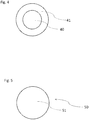
- An example of a non-detailed 2D representation of an open target duct is provided in Figure 4 .
- Figure 4 depicts an open target duct 40
- Figure 5 depicts a closed target duct, showing a cover 51.
- the inner circle and outer circle in Figure 4 are related to an inner and an outer diameter of a flange 41, respectively.
- a related 3D representation may be constructed.
- Figure 6 depicts a 3D representation of an open target duct 40 connected to a fluid transfer line 42
- Figure 7 depicts a 3D representation of a closed target duct.
- step 103 the control system 30 determines, based on matching the representation of the object in the scene with a plurality of predetermined representations comprising representations of open target ducts, whether or not an open target duct 40 is present in the scene. In case it is determined that the open target duct 40 is present in the scene, it is efficient to move the imaging system 20 along a trajectory such that the open target duct 40 remains present in the scene.
- step 103 If, in step 103, the control system 30 has determined that an open target duct 40 is present in the scene, the flow continues with step 104.
- step 103 the control system 30 has determined that there is no open target duct 40 present in the scene, the flow returns to step 101.
- step 104 the control system 30 determines, if the open target duct 40 is present in the scene, an estimated position of the open target duct 40 with respect to the coupling device 18 or the imaging system 20. Determining the position may be based on the (3D) representation of the open target duct 40.
- step 106 the control system 30 constructs, based on the image data, a 3D representation of the open target duct 40.
- the control system 30 receives, via the imaging signal 21, additional images of the scene captured by the imaging system 20.
- the control system 30 may control the at least one actuator 17 to move the coupling device 18 towards the open target duct 40 to enable the imaging system 20 to capture more and better images of the open target duct 40.
- step 108 the control system 30 improves, based on the additional images of the scene captured, an representation accuracy of the 3D representation of the open target duct 40.
- the images may not be detailed enough to determine whether the coupling device 18 is compatible with the (open) target duct 40. Improving the representation accuracy of the 3D representation may continue until the 3D representation of the open target duct 40 can be matched with predetermined 3D representations of open target ducts.
- Figures 8 and 9 depict, from different viewpoints, a detailed 3D representation of the open target duct that may be used to determine characterizing properties such as its shape, inner diameter, outer diameter, diameter of holes 43 and the plurality of the holes 43.
- step 109 the control system 30 tries to determine a characteristic property of the open target duct 40, based on matching the 3D representation with the improved representation accuracy of the open target duct 40 with a plurality of predetermined 3D representations comprising 3D representations of open target ducts with predetermined characteristic properties.
- step 109 the control system 30 is unable to determine a characteristic property of the open target duct 40, the flow returns to step 107.
- step 109 the control system 30 is able to determine a characteristic property of the open target duct 40, the flow continues with step 110.
- step 110 the control system 30 determines whether a characteristic property of the open target duct 40 can be determined, based on matching the 3D representation of the open target duct 40 with a plurality of predetermined 3D representations comprising 3D representations of open target ducts with predetermined characteristic properties.
- step 111 the control system 30 determines, based on the determined characteristic property of the open target duct 40, whether or not the coupling device 18 is compatible with the open target duct 40, wherein a coupling device 18 is compatible with the open target duct 40 if the coupling device 18 can be reliably connected to the open target duct 40.
- step 111 If, in step 111, the control system 30 has determined that the coupling device 18 is compatible with the open target duct 40, the flow continues with step 112.
- step 111 If, in step 111, the control system 30 has determined that the coupling device 18 is not compatible with the open target duct 40, the flow continues with step 113.
- step 112 the control system 30 controls, if the coupling device 18 is compatible with the open target duct, the at least one actuator 17 via the actuation signal 31 to move the coupling device 18 towards the open target duct 40.
- a preferred trajectory 75 of the coupling device 18 towards the open target duct 40 is depicted in Figure 12 , wherein the coupling device avoids an obstacle 70 that may be mounted on the ship 60, in particular mounted on a deck 61 of the ship.
- the coupling device 18 moves at a first height h1 towards the open target duct 40 and then transitions the coupling device 18 to a second height h2, wherein the first height h1 is higher than the second height h2, and wherein the second height h2 is substantially the same height as the height of the centre of the open target duct 40.
- the first height h1 and the second height h2 are heights with respect to a (virtual) horizontal plane 90, that may has an identical height as the height of a water surface, a pier or a shore.
- step 113 the control system 30 aborts the coupling process if in step 111 it is determined that open target duct 40 is not compatible with the coupling device 18.
- Figure 14 depicts a second flow diagram of steps associated to the invention.
- Figure 14 depicts steps of a marine loading method for a marine loading system 10, wherein the arrows indicate an efficient order to perform the plurality of steps.
- Some steps of the second flow diagram are similar to steps of the first flow diagram depicted in Figure 13 , but the flow diagram of Figure 14 comprises a few modifications and additional steps as described in the following.
- step 201 after the control system 30, in step 102, has constructed a representation of an object in the scene, the control system 30 checks whether or not for all objects in the scene a representation is constructed. This check is performed in case there may be multiple target ducts present in the scene. It may be preferable to first determine whether a ship 60 is present in the scene and thereafter whether target ducts are present on the ship 60.
- step 201 the control system 30 has determined that not for all objects in the scene a representation is constructed, the flow returns to step 102 to construct a representation of another object.
- step 201 If, in step 201, the control system 30 has determined that for all objects in the scene a representation is constructed, the flow continues with step 103.
- step 203 after the control system 30, in step 103, has determined that at least one open target duct 40 is present in the scene, the open target duct 40 is selected to which the coupling device 18 should connect. In case only one open target duct 40 is present in the scene, this one open target duct 40 is selected. In case multiple open target ducts 40 are present in the scene, it may be preferable to communicate the number and approximate locations of the open target ducts 40 to an operator who then decides to which open target duct 40 the coupling device 18 should connect. Alternatively, selecting the open target duct 40 may be performed by a computer, without human intervention.
- step 204 after the control system 30, in step 103, has determined that no open target duct 40 is present in the scene, the control system 30 determines, based on matching the objects in the scene with a plurality of predetermined 3D representations comprising 3D representations of closed target ducts, whether or not a closed target duct 50 is present in the scene. In case a closed target duct 50 is present in the scene and/or in the case a closed target duct 50 is not present in the scene, it is preferable to continue receiving image data to continue looking for open target ducts 40.
- step 204 the control system 30 has determined that no closed target duct 50 is present in the scene, the flow returns to step 101.
- step 204 the control system 30 has determined that a closed target duct 50 is present in the scene, the flow continues with step 205. Additionally, the flow may return to step 101 as well.
- step 205 the control system 30 informs an operator or computer that a closed target duct 50 is present in the scene, that may use this information to initiate the opening of the closed target duct 50, which may be done by removing a cover 51.
- step 206 after the control system 30, in step 108, improved the representational accuracy, the control system 30 improves, based on the 3D representation of the open target duct 40 with the improved representational accuracy, a position accuracy of the estimated position of the open target duct 40 with respect to the coupling device 18. This increased accuracy of the position is beneficial to move the coupling device 18 more precise towards the open target duct 40.
- step 207 after the coupling device 18, in step 112, has moved towards the open target duct 40, the control system 30 receives, via the imaging signal 21, detailed image data associated to least one detailed image of the open target duct 40. Since this image is taken when the coupling device 18 has moved relatively close to the open target duct 40, an image of the open target duct 40 can be obtained that comprises relatively fine details, such that even small defects 43 may be visible on the detailed image (see Figure 11 ).
- step 208 the control system 30 determines whether or not the open target duct 40 has a defect 45, based on the detailed image data and on matching the detailed image data with image defect data associated to a plurality of predetermined images of open target ducts with defects and a plurality of predetermined images of open target ducts without defects. In particular defects on the seal face 44 are important to detect.
- step 208 the control system 30 has determined that the open target duct 40 has no defect, the flow continues with step 209.
- step 208 the control system 30 has determined that the open target duct 40 has a defect 45, the flow continues with step 210.
- step 209 the coupling device connects to the open target duct 40 after it is determined that the open target duct 40 is compatible with the coupling device 18 and that the open target duct 40 has no defects.
- step 210 the control system 30 aborts the coupling process because the open target duct 40 is not compatible with the coupling device 18 or because the open target duct 40 has a defect 45.
- a method for marine loading comprising: providing a marine loading system comprising: a marine loading arm, at least one fluid transfer line provided with a coupling device, at least one actuator being adapted to move the marine loading arm and to position the coupling device and a imaging system configured to capture a plurality of images.
- the method further comprises:
- Coupled is defined as connected, although not necessarily directly, and not necessarily mechanically (e.g. magnetically).
- a single processor or other unit, or multiple processors or other units may fulfil control the functions of several test routine steps recited in the claims.
Landscapes
- Engineering & Computer Science (AREA)
- Mechanical Engineering (AREA)
- Chemical & Material Sciences (AREA)
- Combustion & Propulsion (AREA)
- Ocean & Marine Engineering (AREA)
- Theoretical Computer Science (AREA)
- General Physics & Mathematics (AREA)
- Data Mining & Analysis (AREA)
- Physics & Mathematics (AREA)
- Bioinformatics & Computational Biology (AREA)
- Computer Vision & Pattern Recognition (AREA)
- Evolutionary Biology (AREA)
- Evolutionary Computation (AREA)
- Bioinformatics & Cheminformatics (AREA)
- General Engineering & Computer Science (AREA)
- Life Sciences & Earth Sciences (AREA)
- Artificial Intelligence (AREA)
- Software Systems (AREA)
- Multimedia (AREA)
- Studio Devices (AREA)
- Processing Or Creating Images (AREA)
Claims (15)
- Verfahren zur Schiffsbeladung, wobei das Verfahren Folgendes umfasst:• Bereitstellen eines Schiffsbeladungssystems (10), umfassend:∘ einen Schiffsladearm, der umfasst:- zumindest eine Fluidtransferleitung (16), die mit einer Kupplungsvorrichtung (18) versehen ist;- zumindest einen Aktuator (17), der geeignet ist, den Schiffsladearm zu bewegen und die Kupplungsvorrichtung zu positionieren;ein Bildgebungssystem (20), das eingerichtet ist, eine Vielzahl von Bildern aufzunehmen, wobei die Position und die Ausrichtung des Bildgebungssystems in Bezug auf die Kupplungsvorrichtung bestimmbar ist; undwobei das Verfahren des Weiteren umfasst:a. Empfangen von Bilddaten, die der Vielzahl von Bildern einer Szene zugeordnet sind, von dem Bildgebungssystem;b. Konstruieren einer Darstellung eines Objekts in der Szene auf Grundlage der Bilddaten;
dadurch gekennzeichnet, dass das Verfahren des Weiteren umfasst:c. Bestimmen, auf Grundlage des Abgleichs der Darstellung des Objekts in der Szene mit einer Vielzahl von vorbestimmten Darstellungen, die Darstellungen von offenen Zielkanälen umfassen, ob das Objekt einen offenen Zielkanal (40) darstellt, der in der Szene vorhanden ist;d. Bestimmen, falls festgestellt wird, dass der offene Zielkanal in der Szene vorhanden ist, einer geschätzten Position des offenen Zielkanals in Bezug auf die Kupplungsvorrichtung;e. Konstruieren, auf Grundlage der Bilddaten, einer 3D-Darstellung des offenen Zielkanals;f. Bestimmen einer charakteristischen Eigenschaft des offenen Zielkanals, auf Grundlage des Abgleichs der 3D-Darstellung des offenen Zielkanals mit einer Vielzahl von vorbestimmten 3D-Darstellungen, die 3D-Darstellungen von offenen Zielkanälen mit vorbestimmten charakteristischen Eigenschaften umfassen;g. Bestimmen, auf Grundlage der bestimmten charakteristischen Eigenschaft des offenen Zielkanals, ob die Kupplungsvorrichtung mit dem offenen Zielkanal kompatibel ist, wobei eine Kupplungsvorrichtung mit dem offenen Zielkanal kompatibel ist, falls die Kupplungsvorrichtung mit dem offenen Zielkanal verbunden werden kann; undh. Bewegen der Kupplungsvorrichtung, falls die Kupplungsvorrichtung mit dem offenen Zielkanal kompatibel ist, auf Grundlage der geschätzten Position des offenen Zielkanals in Bezug auf die Kupplungsvorrichtung in Richtung des offenen Zielkanals. - Verfahren nach Anspruch 1, wobei die charakteristische Eigenschaft des offenen Zielkanals (40) eine Information über einen Durchmesser des offenen Zielkanals umfasst.
- Verfahren nach Anspruch 1 oder 2, wobei der offene Zielkanal (40) einen Flansch (41) umfasst, und wobei die charakteristische Eigenschaft des offenen Zielkanals Informationen über eine Vielzahl von Ausnehmungen (43) in dem Flansch umfasst.
- Verfahren nach einem der vorangegangenen Ansprüche, des Weiteren umfassend:• Bestimmen, nach Schritt c und vor Schritt d, auf Grundlage des Abgleichs der Darstellung des Objekts in der Szene mit einer Vielzahl vorbestimmter Darstellungen, die Darstellungen von geschlossenen Zielkanälen umfassen, ob das Objekt einen in der Szene vorhandenen geschlossenen Zielkanal (50) darstellt.
- Verfahren nach einem der vorangegangenen Ansprüche, des Weiteren umfassend:• Angeben, ob die Eigenschaft des offenen Zielkanals (40) bestimmt ist; und/oder• Angeben, ob die Kupplungsvorrichtung (18) mit dem offenen Zielkanal kompatibel ist.
- Verfahren nach einem der vorangegangenen Ansprüche, des Weiteren umfassend:• Wiederholen der Schritte b bis e für jedes Objekt in der Szene;• Angeben einer Anzahl offener Zielkanäle (40), die in der Szene vorhanden sind; und• Auswählen, falls die Anzahl offener Zielkanäle größer als eins ist, des offenen Zielkanals, an den die Kupplungsvorrichtung (18) angeschlossen werden soll.
- Verfahren nach einem der vorangegangenen Ansprüche, des Weiteren umfassend:• Empfangen, nach Schritt h, von detaillierten Bilddaten, die zumindest einem detaillierten Bild des offenen Zielkanals (40) zugeordnet sind; und• Bestimmen, ob der offene Zielkanal Defekte (45) aufweist, auf Grundlage der detaillierten Bilddaten und des Abgleichs der detaillierten Bilddaten mit Bilddefektdaten, die einer Vielzahl von vorbestimmten Bildern von offenen Zielkanälen mit Defekten und einer Vielzahl von vorbestimmten Bildern von offenen Zielkanälen ohne Defekte zugeordnet sind.
- Verfahren nach einem der vorangegangenen Ansprüche, des Weiteren umfassend:• Bewegen der Kupplungsvorrichtung in einer ersten Höhe (h1) in Richtung des offenen Zielkanals und anschließendes Umstellen der Kupplungsvorrichtung auf eine zweite Höhe (h2), wobei die erste Höhe höher ist als die zweite Höhe und wobei die zweite Höhe im Wesentlichen die gleiche Höhe wie die Höhe des offenen Zielkanals (40) ist.
- Verfahren nach einem der vorangegangenen Ansprüche, des Weiteren umfassend:• Bewegen des Bildgebungssystems (20) entlang einer Bahn, falls bestimmt wird, dass der offene Zielkanal (40) in der Szene vorhanden ist, so dass der offene Zielkanal in der Szene vorhanden bleibt.
- Verfahren nach einem der vorangegangenen Ansprüche, des Weiteren umfassend:• Bewegen des Bildgebungssystems (20) entlang einer Bahn, falls die geschätzte Position des offenen Zielkanals (40) bestimmt wurde, so dass sich die Ausrichtung des offenen Zielkanals in Bezug auf das Bildgebungssystem ändert;• Erfassen zusätzlicher Bilder der Szene, während sich das Bildgebungssystem bewegt;• Verbessern einer Darstellungsgenauigkeit der Darstellung oder der 3D-Darstellung des offenen Zielkanals auf der Grundlage der zusätzlich erfassten Bilder der Szene.
- Verfahren nach Anspruch 10, des Weiteren umfassend:• Verbesserung, auf Grundlage der 3D-Darstellung des offenen Zielkanals (40) mit der verbesserten Darstellungsgenauigkeit, einer Positionsgenauigkeit der geschätzten Position des offenen Zielkanals in Bezug auf die Kupplungsvorrichtung (18) oder das Bildgebungssystem (20).
- Verfahren nach einem der vorangegangenen Ansprüche, des Weiteren umfassend:• Bewegen des Bildgebungssystems (20) zusammen mit der Kopplungsvorrichtung (18), wobei die relative Position des Bildgebungssystems in Bezug auf die Kopplungsvorrichtung im Wesentlichen gleich bleibt.
- Schiffsbeladungssystem (10), umfassend:• einen Schiffsladearm, der umfasst:∘ zumindest eine Fluidtransferleitung (16), die mit einer Kupplungsvorrichtung (18) versehen ist;∘ zumindest einen Aktuator (17), der geeignet ist, den Schiffsladearm zu bewegen und die Kupplungsvorrichtung zu positionieren;• ein Bildgebungssystem (20), das eingerichtet ist, eine Vielzahl von Bildern aufzunehmen, wobei die Position und die Ausrichtung des Bildgebungssystems in Bezug auf die Kupplungsvorrichtung bestimmbar ist; und• ein Steuerungssystem (30), das in Wirkverbindung mit dem zumindest einen Aktuator und mit dem Bildgebungssystem steht, wobei das Steuerungssystem zu Folgendem eingerichtet ist:a. Empfangen von Bilddaten, die der Vielzahl von Bildern einer Szene zugeordnet sind, von dem Bildgebungssystem;b. Konstruieren einer Darstellung eines Objekts in der Szene auf Grundlage der Bilddaten;
dadurch gekennzeichnet, dass das Steuerungssystem des Weiteren zu Folgendem eingerichtet ist:c. Bestimmen, auf Grundlage des Abgleichs der Darstellung des Objekts in der Szene mit einer Vielzahl von vorbestimmten Darstellungen, die Darstellungen von offenen Zielkanälen umfassen, ob das Objekt einen offenen Zielkanal (40) darstellt, der in der Szene vorhanden ist;d. Bestimmen, falls festgestellt wird, dass der offene Zielkanal in der Szene vorhanden ist, einer geschätzten Position des offenen Zielkanals in Bezug auf die Kupplungsvorrichtung;e. Konstruieren, auf Grundlage der Bilddaten, einer 3D-Darstellung des offenen Zielkanals;f. Bestimmen einer charakteristischen Eigenschaft des offenen Zielkanals, auf Grundlage des Abgleichs der 3D-Darstellung des offenen Zielkanals mit einer Vielzahl von vorbestimmten 3D-Darstellungen, die 3D-Darstellungen von offenen Zielkanälen mit vorbestimmten charakteristischen Eigenschaften umfassen;g. Bestimmen, auf Grundlage der bestimmten charakteristischen Eigenschaft des offenen Zielkanals, ob die Kupplungsvorrichtung mit dem offenen Zielkanal kompatibel ist, wobei eine Kupplungsvorrichtung mit dem offenen Zielkanal kompatibel ist, falls die Kupplungsvorrichtung mit dem offenen Zielkanal verbunden werden kann; undh. Steuern, falls die Kupplungsvorrichtung mit dem offenen Zielkanal kompatibel ist, des zumindest einen Aktuators derart, dass er die Kupplungsvorrichtung auf Grundlage der geschätzten Position des offenen Zielkanals in Bezug auf die Kupplungsvorrichtung in Richtung des offenen Zielkanals bewegt. - Schiffsbeladungssystem nach Anspruch 13, des Weiteren umfassend Mittel zum Bewegen des Bildgebungssystems (20), wobei das Bildgebungssystem insbesondere auf dem Schiffsbeladungsarm, auf einer Drohne (80) und/oder auf einem beweglichen Arm (85) montiert ist.
- Computerprogramm, das Computerbefehle umfasst, die, wenn sie in ein Steuerungssystem des Schiffsbeladungssystems (10) nach einem der Ansprüche 13 bis 14 geladen werden, das Steuersystem veranlassen, die Schritte a bis h durchzuführen.
Applications Claiming Priority (2)
| Application Number | Priority Date | Filing Date | Title |
|---|---|---|---|
| NL2021555A NL2021555B1 (en) | 2018-09-04 | 2018-09-04 | Method and system for marine loading, computer readable medium and computer program for a marine loading system |
| PCT/NL2019/050566 WO2020050715A1 (en) | 2018-09-04 | 2019-09-02 | Method and system for marine loading, computer readable medium and computer program for a marine loading system |
Publications (2)
| Publication Number | Publication Date |
|---|---|
| EP3847092A1 EP3847092A1 (de) | 2021-07-14 |
| EP3847092B1 true EP3847092B1 (de) | 2021-12-29 |
Family
ID=63966023
Family Applications (1)
| Application Number | Title | Priority Date | Filing Date |
|---|---|---|---|
| EP19782783.5A Active EP3847092B1 (de) | 2018-09-04 | 2019-09-02 | Verfahren und system zur schiffsbeladung, computerlesbares medium und computerprogramm für ein schiffsladesystem |
Country Status (9)
| Country | Link |
|---|---|
| US (1) | US11059546B1 (de) |
| EP (1) | EP3847092B1 (de) |
| CA (1) | CA3109707A1 (de) |
| CY (1) | CY1125188T1 (de) |
| DK (1) | DK3847092T3 (de) |
| ES (1) | ES2908861T3 (de) |
| NL (1) | NL2021555B1 (de) |
| SA (1) | SA521421381B1 (de) |
| WO (1) | WO2020050715A1 (de) |
Families Citing this family (2)
| Publication number | Priority date | Publication date | Assignee | Title |
|---|---|---|---|---|
| FR3131290A1 (fr) * | 2021-12-23 | 2023-06-30 | Fmc Loading Systems | Système de chargement marine à commande de déplacement automatique et procédé associé |
| USD995398S1 (en) * | 2022-04-27 | 2023-08-15 | J. De Jonge Beheer B.V. | Marine loading arm |
Family Cites Families (6)
| Publication number | Priority date | Publication date | Assignee | Title |
|---|---|---|---|---|
| US6317953B1 (en) * | 1981-05-11 | 2001-11-20 | Lmi-Diffracto | Vision target based assembly |
| US4758970A (en) * | 1984-08-08 | 1988-07-19 | Emco Wheaton, Inc. | Marine loading arm monitoring system |
| FR2931450B1 (fr) * | 2008-05-22 | 2010-12-17 | Fmc Technologies Sa | Dispositif de fourniture d'informations de positionnement d'une bride mobile de systeme de chargement marine |
| FR2931451B1 (fr) * | 2008-05-22 | 2010-12-17 | Fmc Technologies Sa | Dispositif de commande pour systeme de chargement et/ou dechargement de fluides |
| KR20150066744A (ko) * | 2013-12-09 | 2015-06-17 | 대우조선해양 주식회사 | 액상화물 하역 시스템의 로딩암 자동 타게팅 장치 및 로딩암 자동 타게팅 방법 그리고 이를 구비한 액상화물 하역 시스템 |
| SE538470C2 (sv) * | 2014-02-21 | 2016-07-12 | Celective Source Ab | Förfarande för att upprätta en temporär anslutning |
-
2018
- 2018-09-04 NL NL2021555A patent/NL2021555B1/en not_active IP Right Cessation
-
2019
- 2019-09-02 CA CA3109707A patent/CA3109707A1/en active Pending
- 2019-09-02 EP EP19782783.5A patent/EP3847092B1/de active Active
- 2019-09-02 US US17/270,902 patent/US11059546B1/en active Active
- 2019-09-02 DK DK19782783.5T patent/DK3847092T3/da active
- 2019-09-02 WO PCT/NL2019/050566 patent/WO2020050715A1/en unknown
- 2019-09-02 ES ES19782783T patent/ES2908861T3/es active Active
-
2021
- 2021-03-03 SA SA521421381A patent/SA521421381B1/ar unknown
-
2022
- 2022-03-24 CY CY20221100234T patent/CY1125188T1/el unknown
Also Published As
| Publication number | Publication date |
|---|---|
| US11059546B1 (en) | 2021-07-13 |
| WO2020050715A1 (en) | 2020-03-12 |
| EP3847092A1 (de) | 2021-07-14 |
| ES2908861T3 (es) | 2022-05-04 |
| DK3847092T3 (da) | 2022-01-31 |
| CA3109707A1 (en) | 2020-03-12 |
| CY1125188T1 (el) | 2024-02-16 |
| US20210214051A1 (en) | 2021-07-15 |
| NL2021555B1 (en) | 2019-09-12 |
| SA521421381B1 (ar) | 2022-08-30 |
Similar Documents
| Publication | Publication Date | Title |
|---|---|---|
| EP3847092B1 (de) | Verfahren und system zur schiffsbeladung, computerlesbares medium und computerprogramm für ein schiffsladesystem | |
| CN102036905B (zh) | 用于海上流体输送系统的控制设备 | |
| KR101683274B1 (ko) | 무인항공기를 이용한 선박 접안 지원 시스템 및 그 방법 | |
| KR101873743B1 (ko) | 선박 저면 검사용 수중영상시스템 | |
| US20170276260A1 (en) | Pipe handling system and method of joining pipe sections | |
| JP2012051561A (ja) | 無人の水中航走体および無人の水中航走体を運転するための方法 | |
| CN113386930B (zh) | 一种应用于桥墩检修的水下机器人及其检修方法 | |
| BRPI0708621A2 (pt) | ferramentas de reparo e manuteção de tubulações submarinas e métodos para substituição de tubulações rompidas | |
| CN113525631B (zh) | 一种基于光视觉引导的水下终端对接系统及方法 | |
| KR20150066744A (ko) | 액상화물 하역 시스템의 로딩암 자동 타게팅 장치 및 로딩암 자동 타게팅 방법 그리고 이를 구비한 액상화물 하역 시스템 | |
| CN112009623A (zh) | 一种用于船舶停泊的主动捕获式对接系统 | |
| CN110975194A (zh) | 一种变电站消防机器人辅助方法及系统 | |
| CN109367577A (zh) | 一种列车上水机器人多级定位上水方法 | |
| CN111692965A (zh) | 隔水管自动对接位姿检测与控制方法 | |
| KR20220136471A (ko) | 액화 장치, 방법, 및 시스템 | |
| CN112363510A (zh) | 一种自动驾驶编组车自动对接方法 | |
| US11292563B2 (en) | Methods for subsea vehicles supervised control | |
| CN114602083B (zh) | 一种基于激光视觉融合的自动补给对接系统及其工作方法 | |
| Painumgal et al. | Positioning and control of an AUV inside a water pipeline for non-contact in-service inspection | |
| WO2018066435A1 (ja) | 自己位置推定装置、自己位置推定方法、プログラム、および画像処理装置 | |
| CN209274610U (zh) | 一种列车上水机器人多维度定位上水系统 | |
| EP2721386A1 (de) | Verfahren und system zur in-situ-sichtkontrolle eines ventils | |
| CN109532944A (zh) | 一种列车上水机器人多级定位上水系统 | |
| CN220853449U (zh) | 工程机械辅助停靠系统和工程机械质检系统 | |
| CN212211199U (zh) | 基于可伸缩挂轨机器人的船舶靠岸侧水尺图像采集系统 |
Legal Events
| Date | Code | Title | Description |
|---|---|---|---|
| STAA | Information on the status of an ep patent application or granted ep patent |
Free format text: STATUS: UNKNOWN |
|
| STAA | Information on the status of an ep patent application or granted ep patent |
Free format text: STATUS: THE INTERNATIONAL PUBLICATION HAS BEEN MADE |
|
| PUAI | Public reference made under article 153(3) epc to a published international application that has entered the european phase |
Free format text: ORIGINAL CODE: 0009012 |
|
| STAA | Information on the status of an ep patent application or granted ep patent |
Free format text: STATUS: REQUEST FOR EXAMINATION WAS MADE |
|
| 17P | Request for examination filed |
Effective date: 20210323 |
|
| AK | Designated contracting states |
Kind code of ref document: A1 Designated state(s): AL AT BE BG CH CY CZ DE DK EE ES FI FR GB GR HR HU IE IS IT LI LT LU LV MC MK MT NL NO PL PT RO RS SE SI SK SM TR |
|
| GRAP | Despatch of communication of intention to grant a patent |
Free format text: ORIGINAL CODE: EPIDOSNIGR1 |
|
| STAA | Information on the status of an ep patent application or granted ep patent |
Free format text: STATUS: GRANT OF PATENT IS INTENDED |
|
| DAV | Request for validation of the european patent (deleted) | ||
| DAX | Request for extension of the european patent (deleted) | ||
| INTG | Intention to grant announced |
Effective date: 20210726 |
|
| GRAS | Grant fee paid |
Free format text: ORIGINAL CODE: EPIDOSNIGR3 |
|
| GRAA | (expected) grant |
Free format text: ORIGINAL CODE: 0009210 |
|
| STAA | Information on the status of an ep patent application or granted ep patent |
Free format text: STATUS: THE PATENT HAS BEEN GRANTED |
|
| AK | Designated contracting states |
Kind code of ref document: B1 Designated state(s): AL AT BE BG CH CY CZ DE DK EE ES FI FR GB GR HR HU IE IS IT LI LT LU LV MC MK MT NL NO PL PT RO RS SE SI SK SM TR |
|
| REG | Reference to a national code |
Ref country code: GB Ref legal event code: FG4D |
|
| REG | Reference to a national code |
Ref country code: CH Ref legal event code: EP |
|
| REG | Reference to a national code |
Ref country code: DE Ref legal event code: R096 Ref document number: 602019010531 Country of ref document: DE |
|
| REG | Reference to a national code |
Ref country code: AT Ref legal event code: REF Ref document number: 1458500 Country of ref document: AT Kind code of ref document: T Effective date: 20220115 |
|
| REG | Reference to a national code |
Ref country code: IE Ref legal event code: FG4D |
|
| REG | Reference to a national code |
Ref country code: DK Ref legal event code: T3 Effective date: 20220128 |
|
| REG | Reference to a national code |
Ref country code: NL Ref legal event code: FP |
|
| REG | Reference to a national code |
Ref country code: SE Ref legal event code: TRGR |
|
| REG | Reference to a national code |
Ref country code: NO Ref legal event code: T2 Effective date: 20211229 |
|
| REG | Reference to a national code |
Ref country code: LT Ref legal event code: MG9D |
|
| PG25 | Lapsed in a contracting state [announced via postgrant information from national office to epo] |
Ref country code: RS Free format text: LAPSE BECAUSE OF FAILURE TO SUBMIT A TRANSLATION OF THE DESCRIPTION OR TO PAY THE FEE WITHIN THE PRESCRIBED TIME-LIMIT Effective date: 20211229 Ref country code: LT Free format text: LAPSE BECAUSE OF FAILURE TO SUBMIT A TRANSLATION OF THE DESCRIPTION OR TO PAY THE FEE WITHIN THE PRESCRIBED TIME-LIMIT Effective date: 20211229 Ref country code: FI Free format text: LAPSE BECAUSE OF FAILURE TO SUBMIT A TRANSLATION OF THE DESCRIPTION OR TO PAY THE FEE WITHIN THE PRESCRIBED TIME-LIMIT Effective date: 20211229 Ref country code: BG Free format text: LAPSE BECAUSE OF FAILURE TO SUBMIT A TRANSLATION OF THE DESCRIPTION OR TO PAY THE FEE WITHIN THE PRESCRIBED TIME-LIMIT Effective date: 20220329 |
|
| REG | Reference to a national code |
Ref country code: ES Ref legal event code: FG2A Ref document number: 2908861 Country of ref document: ES Kind code of ref document: T3 Effective date: 20220504 |
|
| REG | Reference to a national code |
Ref country code: GR Ref legal event code: EP Ref document number: 20220400637 Country of ref document: GR Effective date: 20220418 |
|
| REG | Reference to a national code |
Ref country code: AT Ref legal event code: MK05 Ref document number: 1458500 Country of ref document: AT Kind code of ref document: T Effective date: 20211229 |
|
| PG25 | Lapsed in a contracting state [announced via postgrant information from national office to epo] |
Ref country code: LV Free format text: LAPSE BECAUSE OF FAILURE TO SUBMIT A TRANSLATION OF THE DESCRIPTION OR TO PAY THE FEE WITHIN THE PRESCRIBED TIME-LIMIT Effective date: 20211229 Ref country code: HR Free format text: LAPSE BECAUSE OF FAILURE TO SUBMIT A TRANSLATION OF THE DESCRIPTION OR TO PAY THE FEE WITHIN THE PRESCRIBED TIME-LIMIT Effective date: 20211229 |
|
| PG25 | Lapsed in a contracting state [announced via postgrant information from national office to epo] |
Ref country code: SM Free format text: LAPSE BECAUSE OF FAILURE TO SUBMIT A TRANSLATION OF THE DESCRIPTION OR TO PAY THE FEE WITHIN THE PRESCRIBED TIME-LIMIT Effective date: 20211229 Ref country code: SK Free format text: LAPSE BECAUSE OF FAILURE TO SUBMIT A TRANSLATION OF THE DESCRIPTION OR TO PAY THE FEE WITHIN THE PRESCRIBED TIME-LIMIT Effective date: 20211229 Ref country code: RO Free format text: LAPSE BECAUSE OF FAILURE TO SUBMIT A TRANSLATION OF THE DESCRIPTION OR TO PAY THE FEE WITHIN THE PRESCRIBED TIME-LIMIT Effective date: 20211229 Ref country code: PT Free format text: LAPSE BECAUSE OF FAILURE TO SUBMIT A TRANSLATION OF THE DESCRIPTION OR TO PAY THE FEE WITHIN THE PRESCRIBED TIME-LIMIT Effective date: 20220429 Ref country code: EE Free format text: LAPSE BECAUSE OF FAILURE TO SUBMIT A TRANSLATION OF THE DESCRIPTION OR TO PAY THE FEE WITHIN THE PRESCRIBED TIME-LIMIT Effective date: 20211229 Ref country code: CZ Free format text: LAPSE BECAUSE OF FAILURE TO SUBMIT A TRANSLATION OF THE DESCRIPTION OR TO PAY THE FEE WITHIN THE PRESCRIBED TIME-LIMIT Effective date: 20211229 |
|
| PG25 | Lapsed in a contracting state [announced via postgrant information from national office to epo] |
Ref country code: PL Free format text: LAPSE BECAUSE OF FAILURE TO SUBMIT A TRANSLATION OF THE DESCRIPTION OR TO PAY THE FEE WITHIN THE PRESCRIBED TIME-LIMIT Effective date: 20211229 Ref country code: AT Free format text: LAPSE BECAUSE OF FAILURE TO SUBMIT A TRANSLATION OF THE DESCRIPTION OR TO PAY THE FEE WITHIN THE PRESCRIBED TIME-LIMIT Effective date: 20211229 |
|
| PG25 | Lapsed in a contracting state [announced via postgrant information from national office to epo] |
Ref country code: IS Free format text: LAPSE BECAUSE OF FAILURE TO SUBMIT A TRANSLATION OF THE DESCRIPTION OR TO PAY THE FEE WITHIN THE PRESCRIBED TIME-LIMIT Effective date: 20220429 |
|
| REG | Reference to a national code |
Ref country code: DE Ref legal event code: R097 Ref document number: 602019010531 Country of ref document: DE |
|
| PG25 | Lapsed in a contracting state [announced via postgrant information from national office to epo] |
Ref country code: AL Free format text: LAPSE BECAUSE OF FAILURE TO SUBMIT A TRANSLATION OF THE DESCRIPTION OR TO PAY THE FEE WITHIN THE PRESCRIBED TIME-LIMIT Effective date: 20211229 |
|
| PLBE | No opposition filed within time limit |
Free format text: ORIGINAL CODE: 0009261 |
|
| STAA | Information on the status of an ep patent application or granted ep patent |
Free format text: STATUS: NO OPPOSITION FILED WITHIN TIME LIMIT |
|
| 26N | No opposition filed |
Effective date: 20220930 |
|
| PG25 | Lapsed in a contracting state [announced via postgrant information from national office to epo] |
Ref country code: MC Free format text: LAPSE BECAUSE OF FAILURE TO SUBMIT A TRANSLATION OF THE DESCRIPTION OR TO PAY THE FEE WITHIN THE PRESCRIBED TIME-LIMIT Effective date: 20211229 |
|
| REG | Reference to a national code |
Ref country code: CH Ref legal event code: PL |
|
| P01 | Opt-out of the competence of the unified patent court (upc) registered |
Effective date: 20230508 |
|
| PG25 | Lapsed in a contracting state [announced via postgrant information from national office to epo] |
Ref country code: LU Free format text: LAPSE BECAUSE OF NON-PAYMENT OF DUE FEES Effective date: 20220902 |
|
| PG25 | Lapsed in a contracting state [announced via postgrant information from national office to epo] |
Ref country code: LI Free format text: LAPSE BECAUSE OF NON-PAYMENT OF DUE FEES Effective date: 20220930 Ref country code: IE Free format text: LAPSE BECAUSE OF NON-PAYMENT OF DUE FEES Effective date: 20220902 Ref country code: CH Free format text: LAPSE BECAUSE OF NON-PAYMENT OF DUE FEES Effective date: 20220930 |
|
| PGFP | Annual fee paid to national office [announced via postgrant information from national office to epo] |
Ref country code: TR Payment date: 20230828 Year of fee payment: 5 Ref country code: NO Payment date: 20230919 Year of fee payment: 5 Ref country code: NL Payment date: 20230926 Year of fee payment: 5 Ref country code: GB Payment date: 20230921 Year of fee payment: 5 Ref country code: CY Payment date: 20230822 Year of fee payment: 5 |
|
| PGFP | Annual fee paid to national office [announced via postgrant information from national office to epo] |
Ref country code: SE Payment date: 20230921 Year of fee payment: 5 Ref country code: GR Payment date: 20230915 Year of fee payment: 5 Ref country code: FR Payment date: 20230918 Year of fee payment: 5 Ref country code: DK Payment date: 20230921 Year of fee payment: 5 Ref country code: DE Payment date: 20230919 Year of fee payment: 5 Ref country code: BE Payment date: 20230925 Year of fee payment: 5 |
|
| PGFP | Annual fee paid to national office [announced via postgrant information from national office to epo] |
Ref country code: MT Payment date: 20230919 Year of fee payment: 5 |
|
| PGFP | Annual fee paid to national office [announced via postgrant information from national office to epo] |
Ref country code: ES Payment date: 20231019 Year of fee payment: 5 |
|
| PGFP | Annual fee paid to national office [announced via postgrant information from national office to epo] |
Ref country code: IT Payment date: 20230929 Year of fee payment: 5 |