EP3847069B1 - Rear-facing perception system for vehicles - Google Patents
Rear-facing perception system for vehicles Download PDFInfo
- Publication number
- EP3847069B1 EP3847069B1 EP19857520.1A EP19857520A EP3847069B1 EP 3847069 B1 EP3847069 B1 EP 3847069B1 EP 19857520 A EP19857520 A EP 19857520A EP 3847069 B1 EP3847069 B1 EP 3847069B1
- Authority
- EP
- European Patent Office
- Prior art keywords
- frequency band
- corner units
- center unit
- trigger signal
- over
- Prior art date
- Legal status (The legal status is an assumption and is not a legal conclusion. Google has not performed a legal analysis and makes no representation as to the accuracy of the status listed.)
- Active
Links
Images



Classifications
-
- G—PHYSICS
- G06—COMPUTING OR CALCULATING; COUNTING
- G06V—IMAGE OR VIDEO RECOGNITION OR UNDERSTANDING
- G06V20/00—Scenes; Scene-specific elements
- G06V20/50—Context or environment of the image
- G06V20/56—Context or environment of the image exterior to a vehicle by using sensors mounted on the vehicle
-
- H—ELECTRICITY
- H04—ELECTRIC COMMUNICATION TECHNIQUE
- H04B—TRANSMISSION
- H04B7/00—Radio transmission systems, i.e. using radiation field
- H04B7/24—Radio transmission systems, i.e. using radiation field for communication between two or more posts
- H04B7/26—Radio transmission systems, i.e. using radiation field for communication between two or more posts at least one of which is mobile
- H04B7/2621—Radio transmission systems, i.e. using radiation field for communication between two or more posts at least one of which is mobile using frequency division multiple access [FDMA]
-
- B—PERFORMING OPERATIONS; TRANSPORTING
- B60—VEHICLES IN GENERAL
- B60R—VEHICLES, VEHICLE FITTINGS, OR VEHICLE PARTS, NOT OTHERWISE PROVIDED FOR
- B60R1/00—Optical viewing arrangements; Real-time viewing arrangements for drivers or passengers using optical image capturing systems, e.g. cameras or video systems specially adapted for use in or on vehicles
- B60R1/20—Real-time viewing arrangements for drivers or passengers using optical image capturing systems, e.g. cameras or video systems specially adapted for use in or on vehicles
- B60R1/22—Real-time viewing arrangements for drivers or passengers using optical image capturing systems, e.g. cameras or video systems specially adapted for use in or on vehicles for viewing an area outside the vehicle, e.g. the exterior of the vehicle
- B60R1/23—Real-time viewing arrangements for drivers or passengers using optical image capturing systems, e.g. cameras or video systems specially adapted for use in or on vehicles for viewing an area outside the vehicle, e.g. the exterior of the vehicle with a predetermined field of view
- B60R1/26—Real-time viewing arrangements for drivers or passengers using optical image capturing systems, e.g. cameras or video systems specially adapted for use in or on vehicles for viewing an area outside the vehicle, e.g. the exterior of the vehicle with a predetermined field of view to the rear of the vehicle
-
- B—PERFORMING OPERATIONS; TRANSPORTING
- B60—VEHICLES IN GENERAL
- B60R—VEHICLES, VEHICLE FITTINGS, OR VEHICLE PARTS, NOT OTHERWISE PROVIDED FOR
- B60R16/00—Electric or fluid circuits specially adapted for vehicles and not otherwise provided for; Arrangement of elements of electric or fluid circuits specially adapted for vehicles and not otherwise provided for
- B60R16/02—Electric or fluid circuits specially adapted for vehicles and not otherwise provided for; Arrangement of elements of electric or fluid circuits specially adapted for vehicles and not otherwise provided for electric constitutive elements
- B60R16/023—Electric or fluid circuits specially adapted for vehicles and not otherwise provided for; Arrangement of elements of electric or fluid circuits specially adapted for vehicles and not otherwise provided for electric constitutive elements for transmission of signals between vehicle parts or subsystems
- B60R16/0231—Circuits relating to the driving or the functioning of the vehicle
-
- B—PERFORMING OPERATIONS; TRANSPORTING
- B60—VEHICLES IN GENERAL
- B60R—VEHICLES, VEHICLE FITTINGS, OR VEHICLE PARTS, NOT OTHERWISE PROVIDED FOR
- B60R16/00—Electric or fluid circuits specially adapted for vehicles and not otherwise provided for; Arrangement of elements of electric or fluid circuits specially adapted for vehicles and not otherwise provided for
- B60R16/02—Electric or fluid circuits specially adapted for vehicles and not otherwise provided for; Arrangement of elements of electric or fluid circuits specially adapted for vehicles and not otherwise provided for electric constitutive elements
- B60R16/03—Electric or fluid circuits specially adapted for vehicles and not otherwise provided for; Arrangement of elements of electric or fluid circuits specially adapted for vehicles and not otherwise provided for electric constitutive elements for supply of electrical power to vehicle subsystems or for
- B60R16/033—Electric or fluid circuits specially adapted for vehicles and not otherwise provided for; Arrangement of elements of electric or fluid circuits specially adapted for vehicles and not otherwise provided for electric constitutive elements for supply of electrical power to vehicle subsystems or for characterised by the use of electrical cells or batteries
-
- H—ELECTRICITY
- H02—GENERATION; CONVERSION OR DISTRIBUTION OF ELECTRIC POWER
- H02S—GENERATION OF ELECTRIC POWER BY CONVERSION OF INFRARED RADIATION, VISIBLE LIGHT OR ULTRAVIOLET LIGHT, e.g. USING PHOTOVOLTAIC [PV] MODULES
- H02S10/00—PV power plants; Combinations of PV energy systems with other systems for the generation of electric power
-
- H—ELECTRICITY
- H04—ELECTRIC COMMUNICATION TECHNIQUE
- H04N—PICTORIAL COMMUNICATION, e.g. TELEVISION
- H04N23/00—Cameras or camera modules comprising electronic image sensors; Control thereof
- H04N23/60—Control of cameras or camera modules
- H04N23/65—Control of camera operation in relation to power supply
-
- H—ELECTRICITY
- H04—ELECTRIC COMMUNICATION TECHNIQUE
- H04N—PICTORIAL COMMUNICATION, e.g. TELEVISION
- H04N23/00—Cameras or camera modules comprising electronic image sensors; Control thereof
- H04N23/60—Control of cameras or camera modules
- H04N23/65—Control of camera operation in relation to power supply
- H04N23/651—Control of camera operation in relation to power supply for reducing power consumption by affecting camera operations, e.g. sleep mode, hibernation mode or power off of selective parts of the camera
-
- H—ELECTRICITY
- H04—ELECTRIC COMMUNICATION TECHNIQUE
- H04N—PICTORIAL COMMUNICATION, e.g. TELEVISION
- H04N23/00—Cameras or camera modules comprising electronic image sensors; Control thereof
- H04N23/60—Control of cameras or camera modules
- H04N23/695—Control of camera direction for changing a field of view, e.g. pan, tilt or based on tracking of objects
-
- H—ELECTRICITY
- H04—ELECTRIC COMMUNICATION TECHNIQUE
- H04N—PICTORIAL COMMUNICATION, e.g. TELEVISION
- H04N7/00—Television systems
- H04N7/18—Closed-circuit television [CCTV] systems, i.e. systems in which the video signal is not broadcast
- H04N7/181—Closed-circuit television [CCTV] systems, i.e. systems in which the video signal is not broadcast for receiving images from a plurality of remote sources
-
- H—ELECTRICITY
- H04—ELECTRIC COMMUNICATION TECHNIQUE
- H04N—PICTORIAL COMMUNICATION, e.g. TELEVISION
- H04N7/00—Television systems
- H04N7/18—Closed-circuit television [CCTV] systems, i.e. systems in which the video signal is not broadcast
- H04N7/183—Closed-circuit television [CCTV] systems, i.e. systems in which the video signal is not broadcast for receiving images from a single remote source
-
- B—PERFORMING OPERATIONS; TRANSPORTING
- B60—VEHICLES IN GENERAL
- B60R—VEHICLES, VEHICLE FITTINGS, OR VEHICLE PARTS, NOT OTHERWISE PROVIDED FOR
- B60R2300/00—Details of viewing arrangements using cameras and displays, specially adapted for use in a vehicle
- B60R2300/40—Details of viewing arrangements using cameras and displays, specially adapted for use in a vehicle characterised by the details of the power supply or the coupling to vehicle components
- B60R2300/404—Details of viewing arrangements using cameras and displays, specially adapted for use in a vehicle characterised by the details of the power supply or the coupling to vehicle components triggering from stand-by mode to operation mode
-
- B—PERFORMING OPERATIONS; TRANSPORTING
- B60—VEHICLES IN GENERAL
- B60R—VEHICLES, VEHICLE FITTINGS, OR VEHICLE PARTS, NOT OTHERWISE PROVIDED FOR
- B60R2300/00—Details of viewing arrangements using cameras and displays, specially adapted for use in a vehicle
- B60R2300/40—Details of viewing arrangements using cameras and displays, specially adapted for use in a vehicle characterised by the details of the power supply or the coupling to vehicle components
- B60R2300/406—Details of viewing arrangements using cameras and displays, specially adapted for use in a vehicle characterised by the details of the power supply or the coupling to vehicle components using wireless transmission
-
- B—PERFORMING OPERATIONS; TRANSPORTING
- B60—VEHICLES IN GENERAL
- B60R—VEHICLES, VEHICLE FITTINGS, OR VEHICLE PARTS, NOT OTHERWISE PROVIDED FOR
- B60R2300/00—Details of viewing arrangements using cameras and displays, specially adapted for use in a vehicle
- B60R2300/80—Details of viewing arrangements using cameras and displays, specially adapted for use in a vehicle characterised by the intended use of the viewing arrangement
- B60R2300/8093—Details of viewing arrangements using cameras and displays, specially adapted for use in a vehicle characterised by the intended use of the viewing arrangement for obstacle warning
-
- G—PHYSICS
- G05—CONTROLLING; REGULATING
- G05D—SYSTEMS FOR CONTROLLING OR REGULATING NON-ELECTRIC VARIABLES
- G05D1/00—Control of position, course, altitude or attitude of land, water, air or space vehicles, e.g. using automatic pilots
- G05D1/02—Control of position or course in two dimensions
- G05D1/021—Control of position or course in two dimensions specially adapted to land vehicles
- G05D1/0231—Control of position or course in two dimensions specially adapted to land vehicles using optical position detecting means
-
- G—PHYSICS
- G05—CONTROLLING; REGULATING
- G05D—SYSTEMS FOR CONTROLLING OR REGULATING NON-ELECTRIC VARIABLES
- G05D1/00—Control of position, course, altitude or attitude of land, water, air or space vehicles, e.g. using automatic pilots
- G05D1/02—Control of position or course in two dimensions
- G05D1/021—Control of position or course in two dimensions specially adapted to land vehicles
- G05D1/0257—Control of position or course in two dimensions specially adapted to land vehicles using a radar
-
- Y—GENERAL TAGGING OF NEW TECHNOLOGICAL DEVELOPMENTS; GENERAL TAGGING OF CROSS-SECTIONAL TECHNOLOGIES SPANNING OVER SEVERAL SECTIONS OF THE IPC; TECHNICAL SUBJECTS COVERED BY FORMER USPC CROSS-REFERENCE ART COLLECTIONS [XRACs] AND DIGESTS
- Y02—TECHNOLOGIES OR APPLICATIONS FOR MITIGATION OR ADAPTATION AGAINST CLIMATE CHANGE
- Y02E—REDUCTION OF GREENHOUSE GAS [GHG] EMISSIONS, RELATED TO ENERGY GENERATION, TRANSMISSION OR DISTRIBUTION
- Y02E10/00—Energy generation through renewable energy sources
- Y02E10/50—Photovoltaic [PV] energy
Definitions
- This document relates to vehicle monitoring and control.
- Autonomous vehicle navigation is a technology for sensing the position and movement of a vehicle and, based on the sensing, autonomously control the vehicle to navigate towards a destination.
- Autonomous vehicle navigation can have important applications in transportation of people, goods and services.
- US2015/172518 discloses examples of prior art autonomous vehicle navigation methods and systems.
- a self-powered and an automatically synchronizing rear-facing perception system which includes a center unit and two corner units, is installed at the rear of a vehicle or on a semi-trailer truck (commonly referred to as a tractor-trailer or a "semi") and provides an unobstructed of an area around a rear of the vehicle.
- the corner and center units wirelessly communicate with a control unit located adjacent to the driver of the vehicle.
- a rear-facing perception system contains two corner units and a center unit, with each of the two corner units and the center unit including a camera module and a dual-band transceiver.
- the method includes pairing with a control unit by communicating, using the dual-band transceiver, over at least a first frequency band, transmitting, upon successfully pairing, a first trigger signal to the two corner units, where the first trigger signal is transmitted over a second frequency band non-overlapping with the first frequency band, and switching, subsequent to transmitting the first trigger signal, to an active mode, where the first trigger signal causes the two corner units to switch to the active mode, where the power module includes a battery, and where the active mode includes orienting the camera modules on the center unit and the two corner units to provide an unobstructed view of an area around a rear of the vehicle.
- the above-described method is embodied in the form of processor-executable code and stored in a computer-readable program medium.
- a backup camera may maintain a driver's control and visibility while operating a vehicle. For example, it can prevent backing up over someone (with toddlers and pets being particularly susceptible) or something, and may assist with parallel parking while avoiding damage to adjacent vehicles. In another example, and if the vehicle were run into by another vehicle, the rear-facing perception system may provide evidence of the incidence for insurance purposes.
- a rear-facing perception system can increase the operational safety of autonomous vehicles. Unlike passenger cars, where a rear-facing camera is permanently installed in the vehicle, some applications of autonomous vehicles may use rear perception systems only occasionally. For example, in cargo delivery business, truck cabs (cabins or tractors) are often attached to different cargo holds or trailers. Therefore, it would be useful to include a rear-perception system that requires very little or no installation when a truck cab is attached to another trailer. In particular, it would be beneficial if the truck driver does not have to attach cables from the rear perception system portion on the trailer to a display and other electronics in the cabin. Easy formation and activation of rear perception system in such cases saves the truck driver the additional time and work and eliminates manual errors in connecting and setting up the system.
- Some desirable features of such a system may include: (i) installation capabilities on trailers of semi-trailer trucks, thereby providing complete rear perception without blind spots, (ii) low-cost and self-powered, (iii) easily installable and detachable, (iv) the ability to wirelessly communicate with the driver, (v) precisely perceive the locations of all objects in the backup route, and (vi) provide automated calibration and synchronization.
- FIG. 1 shows an example of the rear-facing perception system installed on a semi-trailer truck (commonly referred to as a tractor-trailer).
- a center integration unit (CIU, 125) a left corner integration unit (LIU, 135-1) and a right corner integration unit (RIU, 135-2) are mounted on the trailer 115, and a vehicle control unit (VCU, 145) and a telematics box 155 are mounted on the tractor 105 of the tractor-trailer.
- CUA center integration unit
- LIU left corner integration unit
- RAU right corner integration unit
- VCU vehicle control unit
- a subset of components of the rear-facing perception system (the CIU, LIU and RIU) shown in FIG. 1 may be advantageously installed on the rear and/or sides of the trailer to provide full rear perception coverage, with no blind spots or zones.
- Other advantageous features of embodiments of the disclosed technology include, but are not limited to, battery or solar panels to enable self-power capabilities (e.g., no reliance on wires or an external power source), easy installation capabilities (e.g., attached to be firmly secured, and then easily detached), wireless communication capabilities that obviate the need for complex electrical and mechanical construction, and which can support over-the-air (OTA) updates, and automated synchronization and calibration capabilities.
- the CIU, LIU and RIU may include a variety of different sensors whose information may be fused to enable precise detection of objects and/or people that may be present behind the vehicle.
- the CIU, LIU and RIU include an attachment mechanism that is configured to enable easy attachability and detachability of the integration units to the vehicle or trailer of a tractor-trailer.
- the attachment mechanism may be a magnetic panel that may be used to easily affix the integration units to the trailer.
- a suction panel or a hook-and-fastener system may be used for the attachment mechanism.
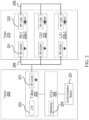
- FIG. 2 shows a block diagram of an example rear-facing perception system, and is one example of packing functional (e.g., communication) sub-components into the components described in the context of FIG. 1 .
- embodiments of the disclosed technology may support communications in a number of different frequency bands and using multiple standards. This feature advantageously provides the components (or modules) the ability to simultaneously communicate, without interfering with the communication of other components or modules.
- the tractor 205 include the VCU 245, the telematics box 255, and a synchronization button 231 (for manual synchronization, which will be discussed later in this document).
- the telematics box may include a dual-band transceiver that supports communications using the LTE standard 223 as well as radio frequency (RF) communications in an Ultra High Frequency (UHF) band 221 (e.g., using a low power device 433 MHz (LPD433)).
- RF radio frequency
- the LTE transceiver 223 may be used by the tractor to provide the driver with updates from traffic and map services, whereas the RF-433M transceiver 221 may be used to communicate with the CIU, LIU and/or RIU that are attached to the trailer 215.
- the VCU 245 may include an EEPROM (electrically erasable programmable read-only memory) 224 that may be configured to store the addresses and/or IDs for each of the components of the rear-facing perception system, in order to enable transmitting data and control signals to/from each component independently.
- EEPROM electrically erasable programmable read-only memory
- the trailer 215 may include the CIU 225, the LIU 235-1 and the RIU 235-2.
- each of the integration units may include a dual-band transceiver that supports RF communications in a UHF band as well as in a Low Frequency (LF) band.
- the RF-433M transceiver 221 may be used to communicate with the VCU 245 in the tractor (as indicated by the dashed lines 298), whereas the 125 kHz RFID (Radio Frequency IDentification) module 222 may be used to communicate between the integration units (as indicated by the dashed lines 299).
- different frequency bands and alternate wireless protocols and devices may be employed in the operation of the rear-facing perception system.
- the VCU and integration units may use Bluetooth, Zigbee, direct short-range communications (DSRC) based on the 802.11p wireless standard, and so on.
- DSRC direct short-range communications
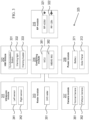
- FIG. 3 shows a block diagram of an example center integration unit (CIU) of a rear-facing perception system.
- the CIU may include seven modules: an ultrasonic module 311, a human-machine interaction (HMI) module 312, a radar module 313, a computing module 314, an RF module 316, a camera module 317, and a power module 318.
- HMI human-machine interaction
- RF radio frequency
- the ultrasonic module 311 may include a left sensor 341 and a right sensor 342, which are installed on the left and right corners of the trailer, respectively.
- the ultrasonic module 311 may be used not only to detect the presence of objects, but to ascertain their distance from the vehicle.
- the camera module 317 may include a normal camera 361 and/or a fisheye camera 362 (e.g., to provide extremely wide angles of view ranging from 100 0 -180 0 ) to provide a view of the area around the rear of the vehicle.
- the inputs of the ultrasonic module 311 and/or the camera module 317 may be used independently to provide precise perception of any obstacles behind the vehicle.
- the inputs from the camera module 317 and the ultrasonic module 311 may be combined, or fused, prior to being used for detection of obstacles and people behind the vehicle.
- augmenting the camera module 317 with the ultrasonic module 311 enables the rear-facing perception system to accurately determine the distances of objects from the vehicle, as well as to operate in low light conditions or even in full darkness.
- the radar module 313 may include a 24 GHz radar module 351, which is configured to augment the camera module 317.
- the radar module 313 is able to detect obstacles in any weather conditions. Combining the camera and radar modules enables the rear-facing perception system to accurately operate in the presence of fog or mist, thereby ensuring the safety of the autonomous vehicles even in adverse situations.
- the HMI module 312 may include a synchronization button 331, a warning light 332 and a warning buzzer 333.
- the synchronization button 331 may be configured to activate the corner integration units as part of the manual synchronization process between the VCU and the CIU, LIU and RIU.
- the warning light 332 and warning buzzer 333 may be configured to provide a visual and aural stimulus when the rear-facing perception system is operational.
- the computing module 314 includes a microcontroller unit (MCU, 381) and a Micro-Electro-Mechanical System (MEMS) based Inertial Measurement Unit (IMU).
- MCU microcontroller unit
- MEMS Micro-Electro-Mechanical System
- IMU Inertial Measurement Unit
- an IMU is an electronic device that measures and reports a body's specific force, angular rate, and sometimes the magnetic field surrounding the body, using a combination of accelerometers and gyroscopes, sometimes also magnetometers.
- the MCU may control the MEMS IMU and/or other components to ensure that the rear-facing perception system is operating in an energy-efficiency manner to ensure vehicular and personnel safety.
- the RF module 316 includes a dual-band transceiver that supports RF communications in UHF and LF bands.
- the RF-433M transceiver 321 may be used to communicate with the VCU, whereas the 125 kHz RFID module 322 may be used to communicate with the LIU and RIU.
- the UHF and LF frequency bands are non-overlapping in frequency.
- the dual-band communications may be orthogonal in time (e.g., using TDMA (time division multiple access)) or in structure (e.g., using CDMA (code division multiple access)).
- the power module 318 includes a battery 371 and/or a solar panel 372. More generally, the power module 318 is a self-powered source for the various components of the rear-facing perception system that does not require a constant connection to the power grid. In some embodiments, the power module 318 may be periodically re-charged to ensure that the various components function as intended during operation of the vehicle.
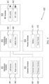
- FIG. 4 shows a block diagram of an example corner unit of a rear-facing perception system.
- This example includes some features and/or components that are similar to those shown in FIG. 3 , and described above. At least some of these features and/or components may not be separately described in this section.
- the LIU and/or RIU may include five modules: an ultrasonic module 411, a computing module 414, an RF module 416, a camera module 417, and a power module 418.
- the camera module 417 includes mechanisms to keep the respective normal and fisheye cameras of the CIU, LIU and RIU clean.
- a camera cleaning system may be configured to spray a cleaning solvent (or water) onto the camera lens, followed by a puff of air to dry the camera lens.
- the VCU may provide the driver of the vehicle with an indication or reminder to ensure that the cameras are clean prior to operating the vehicle.
- FIG. 5 shows a flowchart of an example method for manually synchronizing a rear-facing perception system.
- the manual synchronization process 500 begins at step 510, when the synchronization button on the CIU (e.g. synchronization button 331 as shown in FIG. 3 ) is pressed. Pressing the CIU synchronization button transmits a trigger signal using, for example, the 125 kHz RFID module in the dual-band transceiver (step 530). This trigger signal may be a synchronization signal for the LIU and RIU.
- the synchronization button on the CIU e.g. synchronization button 331 as shown in FIG. 3
- Pressing the CIU synchronization button transmits a trigger signal using, for example, the 125 kHz RFID module in the dual-band transceiver (step 530).
- This trigger signal may be a synchronization signal for the LIU and RIU.
- step 510 may be followed by pressing the synchronization button on the tractor (e.g., the synchronization button 231 in FIG. 2 , which may be located near the on-board diagnostics (OBD) port).
- OBD on-board diagnostics
- the manual synchronization process continues with step 550, wherein the CIU, LIU and RIU send their identification information to the VCU using, for example, the RF-433M module in the dual-band transceiver. If this process is successful (step 560), the VCU stores the IDs in the EEPROM (e.g., EEPROM 224 in FIG. 2 ). If the IDs are not successfully saved in the VCU, the manual synchronization process aborts (and exits, step 580).
- the EEPROM e.g., EEPROM 224 in FIG. 2
- FIG. 6 shows a flowchart of another example method for automatically synchronizing a rear-facing perception system.
- the automatic synchronization process shown in FIG. 6 does not require any manual intervention, and relies on the movement of components of the rear-facing perception system. For example, if a tractor-trailer with a newly installed rear-facing perception system does not need to initially move backwards (and therefore does not need the use of the rear-facing perception system), the forward movement of the tractor-trailer can trigger the automatic synchronization process as described in the context of FIG. 6 .
- the automatic synchronization process 600 beings at step 610, wherein movement of the VCU is detected in the form of signals from one or more axes of the IMU of the VCU.
- the detected signals correspond to an acceleration of less than 1g (step 620)
- the automatic synchronization process terminates (step 670).
- the detected signals correspond to an acceleration of greater than or equal to 1g (e.g., an acceleration of 1 g equates to a rate of change in velocity of approximately 35 kilometers per hour (or 22 miles per hour) for each second that elapses)
- the VCU transmits a synchronization signal using, for example, the RF-433M module in the dual-band transceiver (step 630).
- This synchronization signal is received by the integration units (CIU, LIU, RIU), which then transmit signals corresponding to the axes of their corresponding IMUs (e.g., IMUs 382 and 482 in FIGS. 3 and 4 , for the CIU and LIU/RIU, respectively).
- the IMU signals from the CIU/LIU/RIU are detected (step 640), and if they are similar to the IMU signals from the VCU (step 650), then the IDs from the integration units are stored in the VCU EEPROM (step 660, and similar to step 560 in FIG. 5 ). If, however, there is a mismatch in the IMU signals from the VCU and the integration units (step 650), the automatic synchronization process terminates (step 670).
- the tractor may have just delivered the trailer at a loading dock, and after unhooking the trailer, is leaving from that location.
- the IMU signals from the tractor will register an acceleration of greater than 1g, but the trailer IMU signals will be close to 0g, and no synchronization will occur (as expected since the tractor is not attached to the trailer).
- the manual and automatic synchronization processes described in the context of FIGS. 5 and 6 may typically be performed when a tractor and a trailer are initially paired. As long as the same tractor-trailer combination is in operation, the synchronization process need not be repeated. On the other hand, if the trailer is replaced, then the rear-facing perception system can be detached from the original trailer, affixed to the new trailer, and either the manual or automatic synchronization process can be performed.
- embodiments of the disclosed technology implement wakeup and sleep processes to operate in a power-efficient manner, so as to enables the self-powered CIU, LIU and RIU to operate with frequent recharging.
- FIGS. 7 and 8 provide examples of the wakeup and sleep processes for the rear-facing perception system, respectively.
- FIG. 7 shows a flowchart for an example method 700 for a wakeup process of a rear-facing perception system.
- the method 700 includes, at step 710, the VCU waking up based on an event that may be manually triggered or inferred from the operation of the vehicle. For example, if the vehicle is put in the reverse gear, the VCU automatically wakes up.
- the method 700 includes, at step 720, the VCU transmitting a wakeup signal using, for example, the RF-433M module in the dual-band transceiver.
- the wakeup signal is directed toward the CIU, which then wakes up (step 730) upon receiving the wakeup signal from the VCU.
- the CIU transmits a signal to the VCU in response to the wakeup signal. Additionally, the CIU sends a trigger signal (e.g., a wakeup signal that may be identical to or different from the wakeup signal received from the VCU) to the LIU and RIU using, for example, the 125 kHz RFID module in the dual-band transceiver (step 740). Upon receiving this trigger signal, the LIU and RIU wake up (step 750).
- a trigger signal e.g., a wakeup signal that may be identical to or different from the wakeup signal received from the VCU
- the LIU and RIU wake up (step 750).
- the wakeup process concludes with the VCU receiving a signal from the CIU, LIU and RIU (step 760), acknowledging their active mode of operation.
- Embodiments of the disclosed technology may use the wakeup process to ensure that the rear-facing perception system operates in a power-efficient manner.
- FIG. 8 shows a flowchart for an example method 800 for a sleep process of a rear-facing perception system.
- the sleep process begins with a "sleep event" that includes the VCU detecting that the rear-facing perception system is not required (step 810). For example, if the vehicle is put into cruise control (which typically results in a prolonged period of forward motion), the VCU automatically detects this as a sleep event.
- the driver of the vehicle may explicitly trigger a sleep event if, for example, the tractor-trailer is in a queue at a weight station, and is not required to reverse through the entire process.
- the VCU transmits a sleep signal using, for example, the RF-433M module in the dual-band transceiver (step 820) to the integration units at the rear of the trailer.
- the CIU, LIU and RIU switch to sleep mode (step 830).
- switching to sleep mode includes the power module (e.g., 318 and 418 in FIGS. 3 and 4 for the CIU and LIU/RIU, respectively) switching off one or more modules (e.g., the ultrasonic module, the camera module, the radar module, and so on).
- the power module may switch one or more modules into a power-saving operational mode wherein only some of the functionality of the respective models are active.
- FIG. 9 shows a flowchart for an example method 900 for operating a rear-facing perception system.
- the rear-facing perception system includes two corner units and a center unit, with each of the two corner units (LIE, RIU) and the center unit (CIU) including at least a camera module, a power module and a dual-band transceiver.
- the method 900 which may be implemented in a CIU, includes, at step 910, pairing with a control unit.
- the pairing includes communicating, using the dual-band transceiver, over a first frequency band.
- the power module comprises a battery.
- the method 900 includes, at step 920, transmitting, upon successfully pairing, a first trigger signal to the two corner units.
- the first trigger signal is transmitted over a second frequency band that is non-overlapping with the first frequency band.
- the method 900 includes, at step 930, switching to an active mode after having transmitted the first trigger signal.
- the first trigger signal causes the two corner units to switch to the active mode.
- the active mode includes orienting the camera modules on the center unit and the two corner units to provide an unobstructed view of an area around a rear of the vehicle.
- the first frequency band may include a Ultra High Frequency (UHF) band (e.g., the 433 MHz frequency band) and the second frequency band, which is non-overlapping with the first frequency band, may include a Low Frequency (LF) band (e.g., the 125 kHz frequency band).
- UHF Ultra High Frequency
- LF Low Frequency
- the pairing operation further includes transmitting a synchronization signal to the LIU and RIU over the second frequency band in response to a first manual trigger (e.g., pressing the synchronization button on the CIU), and transmitting an identification signal to the VCU over the first frequency band in response to a second manual trigger (e.g., pressing the synchronization button on the tractor).
- a first manual trigger e.g., pressing the synchronization button on the CIU
- an identification signal e.g., pressing the synchronization button on the tractor
- the pairing operation further includes receiving a synchronization signal from the VCU over the first frequency band, and transmitting a signal corresponding to the movement of the CIU (e.g., the signal from the MEMS IMU indicating an acceleration of greater than 1g in order to continue with the automatic synchronization process).
- a signal corresponding to the movement of the CIU e.g., the signal from the MEMS IMU indicating an acceleration of greater than 1g in order to continue with the automatic synchronization process.
- the method 900 further includes receiving, upon successfully pairing, a first wakeup signal from the VCU over the first frequency band.
- the CIU awakes on the reception of the first wakeup signal, and subsequently triggers the LIU and RIU over the second frequency band.
- the VCU receives signals from the CIU, LIU and RIU, acknowledging their switching over to active mode.
- switching over to active mode includes orienting the camera modules of the CIU, LIU and RIU to provide an unobstructed view of the area around the rear of the vehicle.
- the method 900 further includes transmitting a second trigger signal to the LIU and RIU over the second frequency band.
- the second trigger signal may be a sleep signal, and the CIU may switch over to a power-saving mode after transmitting the second trigger signal. Additionally, the second trigger signal may cause the LIU and RIU to switch to the power-saving mode.
- the VCU may communicate directly with the CIU over the first frequency band. Subsequently, the CIU may communicate with the LIU and RIU (e.g., relay the information received from the VCU) over the second frequency band. In other embodiments, the VCU may communicate directly with each of the CIU, LIU and RIU.
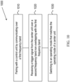
- FIG. 10 shows a flowchart for another example method 1000 for operating a rear-facing perception system.
- This example includes some features and/or steps that are similar to those shown in FIG. 9 , and described above. At least some of these features and/or components may not be separately described in this section.
- the method 1000 which may be implemented in a LIU and/or RIU, includes, at step 1010, pairing with the control unit by communicating, using the dual-band transceiver, over a first frequency band.
- the method 1000 includes, at step 1020, receiving, upon successfully pairing, a trigger signal from the center unit over a second frequency band non-overlapping with the first frequency band.
- the method 1000 includes, at step 1030, switching, subsequent to receiving the trigger signal, to an operating mode that matches the operating mode of the center unit.
- the operating mode may be an active mode or a power-saving mode.
- the power-saving mode may include turning off the camera module
- the active mode may include orienting the camera modules on the center unit and the two corner units to provide an unobstructed view of an area around a rear of the vehicle.
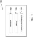
- FIG. 11 shows an example of a hardware platform 1100 that can be used to implement some of the techniques described in the present document.
- the hardware platform 1100 may implement the methods 900 and/or 1000, or may implement the various modules described herein.
- the hardware platform 1100 may include a processor 1102 that can execute code to implement a method.
- the hardware platform 1100 may include a memory 1104 that may be used to store processor-executable code and/or store data.
- the hardware platform 1100 may further include a communication interface 1106.
- the communication interface 1106 may implement one or more of the communication protocols (LTE, Wi-Fi, and so on) described herein.
- Implementations of the subject matter and the functional operations and modules described in this patent document can be implemented in various systems, digital electronic circuitry, or in computer software, firmware, or hardware, including the structures disclosed in this specification and their structural equivalents, or in combinations of one or more of them. Implementations of the subject matter described in this specification can be implemented as one or more computer program products, e.g., one or more modules of computer program instructions encoded on a tangible and non-transitory computer readable medium for execution by, or to control the operation of, data processing apparatus.
- the computer readable medium can be a machine-readable storage device, a machine-readable storage substrate, a memory device, a composition of matter effecting a machine-readable propagated signal, or a combination of one or more of them.
- data processing unit or “data processing apparatus” encompasses all apparatus, devices, and machines for processing data, including by way of example a programmable processor, a computer, or multiple processors or computers.
- the apparatus can include, in addition to hardware, code that creates an execution environment for the computer program in question, e.g., code that constitutes processor firmware, a protocol stack, a database management system, an operating system, or a combination of one or more of them.
- a computer program (also known as a program, software, software application, script, or code) can be written in any form of programming language, including compiled or interpreted languages, and it can be deployed in any form, including as a stand-alone program or as a module, component, subroutine, or other unit suitable for use in a computing environment.
- a computer program does not necessarily correspond to a file in a file system.
- a program can be stored in a portion of a file that holds other programs or data (e.g., one or more scripts stored in a markup language document), in a single file dedicated to the program in question, or in multiple coordinated files (e.g., files that store one or more modules, sub programs, or portions of code).
- a computer program can be deployed to be executed on one computer or on multiple computers that are located at one site or distributed across multiple sites and interconnected by a communication network.
- the processes and logic flows described in this specification can be performed by one or more programmable processors executing one or more computer programs to perform functions by operating on input data and generating output.
- the processes and logic flows can also be performed by, and apparatus can also be implemented as, special purpose logic circuitry, e.g., FPGAs (field programmable gate arrays) or ASICs (application specific integrated circuits).
- processors suitable for the execution of a computer program include, by way of example, both general and special purpose microprocessors, and any one or more processors of any kind of digital computer.
- a processor will receive instructions and data from a read only memory or a random access memory or both.
- the essential elements of a computer are a processor for performing instructions and one or more memory devices for storing instructions and data.
- a computer will also include, or be operatively coupled to receive data from or transfer data to, or both, one or more mass storage devices for storing data, e.g., magnetic, magneto optical disks, or optical disks.
- mass storage devices for storing data, e.g., magnetic, magneto optical disks, or optical disks.
- a computer need not have such devices.
- Computer readable media suitable for storing computer program instructions and data include all forms of nonvolatile memory, media and memory devices, including by way of example semiconductor memory devices, e.g., (E)EPROM and flash memory devices.
- semiconductor memory devices e.g., (E)EPROM and flash memory devices.
- the processor and the memory can be supplemented by, or incorporated in, special purpose logic circuitry.
Landscapes
- Engineering & Computer Science (AREA)
- Multimedia (AREA)
- Signal Processing (AREA)
- Mechanical Engineering (AREA)
- Computer Networks & Wireless Communication (AREA)
- Physics & Mathematics (AREA)
- General Physics & Mathematics (AREA)
- Theoretical Computer Science (AREA)
- Automation & Control Theory (AREA)
- Traffic Control Systems (AREA)
Description
- This document relates to vehicle monitoring and control.
- Autonomous vehicle navigation is a technology for sensing the position and movement of a vehicle and, based on the sensing, autonomously control the vehicle to navigate towards a destination. Autonomous vehicle navigation can have important applications in transportation of people, goods and services. One of the components of autonomous driving, which ensures the safety of the vehicle and its passengers, as well as people and property in the vicinity of the vehicle, is precise perception of the area around the rear of the vehicle.
US2015/172518 discloses examples of prior art autonomous vehicle navigation methods and systems. - Disclosed are devices, systems and methods for a rear-facing perception system for vehicles. In some embodiments, a self-powered and an automatically synchronizing rear-facing perception system, which includes a center unit and two corner units, is installed at the rear of a vehicle or on a semi-trailer truck (commonly referred to as a tractor-trailer or a "semi") and provides an unobstructed of an area around a rear of the vehicle. The corner and center units wirelessly communicate with a control unit located adjacent to the driver of the vehicle.
- In one aspect, according to claim 1, it is provided a method for operating a rear-facing perception unit in a vehicle. According to claim 9, a rear-facing perception system contains two corner units and a center unit, with each of the two corner units and the center unit including a camera module and a dual-band transceiver. The method includes pairing with a control unit by communicating, using the dual-band transceiver, over at least a first frequency band, transmitting, upon successfully pairing, a first trigger signal to the two corner units, where the first trigger signal is transmitted over a second frequency band non-overlapping with the first frequency band, and switching, subsequent to transmitting the first trigger signal, to an active mode, where the first trigger signal causes the two corner units to switch to the active mode, where the power module includes a battery, and where the active mode includes orienting the camera modules on the center unit and the two corner units to provide an unobstructed view of an area around a rear of the vehicle.
- In another aspect, according to
claims 14 and 15, the above-described method is embodied in the form of processor-executable code and stored in a computer-readable program medium. - The above and other aspects and features of the disclosed technology are described in greater detail in the drawings, the description and the claims.
-
-
FIG. 1 shows an example of the rear-facing perception system installed on a semi-trailer truck (commonly referred to as a tractor-trailer). -
FIG. 2 shows a block diagram of an example rear-facing perception system. -
FIG. 3 shows a block diagram of an example center integration unit (CIU) of a rear-facing perception system. -
FIG. 4 shows a block diagram of an example corner integration unit of a rear-facing perception system. -
FIG. 5 shows a flowchart of an example method for manually synchronizing a rear-facing perception system. -
FIG. 6 shows a flowchart of another example method for automatically synchronizing a rear-facing perception system. -
FIG. 7 shows a flowchart for an example method for a wakeup process of a rear-facing perception system. -
FIG. 8 shows a flowchart for an example method for a sleep process of a rear-facing perception system. -
FIG. 9 shows a flowchart for an example method for operating a rear-facing perception system. -
FIG. 10 shows a flowchart for another example method for operating a rear-facing perception system. -
FIG. 11 shows an example of a hardware platform that can implement some techniques described in the present document. - Backover accidents cause thousands of injuries every year because there is a blind spot behind every car and truck. Typically, this blind spot stretches from 4.572 m (15 feet) in smaller cars to more than 7.62 m (25 feet) in larger pickups and SUVs, and to even longer distances for tractor-trailers. Human drivers often rely on their visual inspection of the rear of their vehicle performed prior to entering the vehicle for driving. However, autonomous vehicles do not have such a mechanism. The increasing use of autonomous vehicles makes it important to use precise perception of objects at and around the rear of a vehicle, especially in the case of tractor-trailers that maneuver around static barriers, loading docks, etc. as a part of their daily operations.
- A backup camera (or more generally, a rear-facing perception system) may maintain a driver's control and visibility while operating a vehicle. For example, it can prevent backing up over someone (with toddlers and pets being particularly susceptible) or something, and may assist with parallel parking while avoiding damage to adjacent vehicles. In another example, and if the vehicle were run into by another vehicle, the rear-facing perception system may provide evidence of the incidence for insurance purposes.
- A rear-facing perception system can increase the operational safety of autonomous vehicles. Unlike passenger cars, where a rear-facing camera is permanently installed in the vehicle, some applications of autonomous vehicles may use rear perception systems only occasionally. For example, in cargo delivery business, truck cabs (cabins or tractors) are often attached to different cargo holds or trailers. Therefore, it would be useful to include a rear-perception system that requires very little or no installation when a truck cab is attached to another trailer. In particular, it would be beneficial if the truck driver does not have to attach cables from the rear perception system portion on the trailer to a display and other electronics in the cabin. Easy formation and activation of rear perception system in such cases saves the truck driver the additional time and work and eliminates manual errors in connecting and setting up the system. Furthermore, transport service providers often manage a large inventory of trailers and cabins, and truck trailers may often simply sit in a parking lot when not being used. In such a case, it would be desirable if the electronics associated with a rear perception system is put to use by a simple detachment from a trailer not being used and attachment to another trailer that will be paired with a truck cabin and used.
- Some desirable features of such a system may include: (i) installation capabilities on trailers of semi-trailer trucks, thereby providing complete rear perception without blind spots, (ii) low-cost and self-powered, (iii) easily installable and detachable, (iv) the ability to wirelessly communicate with the driver, (v) precisely perceive the locations of all objects in the backup route, and (vi) provide automated calibration and synchronization.
- The disclosed technology in this document provides solutions that can be used to address the above and other technical issues in the rear-facing monitoring and control of fully- and semi-autonomous vehicles.
FIG. 1 shows an example of the rear-facing perception system installed on a semi-trailer truck (commonly referred to as a tractor-trailer). As shown therein, a center integration unit (CIU, 125), a left corner integration unit (LIU, 135-1) and a right corner integration unit (RIU, 135-2) are mounted on thetrailer 115, and a vehicle control unit (VCU, 145) and atelematics box 155 are mounted on thetractor 105 of the tractor-trailer. - In some embodiments, a subset of components of the rear-facing perception system (the CIU, LIU and RIU) shown in
FIG. 1 may be advantageously installed on the rear and/or sides of the trailer to provide full rear perception coverage, with no blind spots or zones. Other advantageous features of embodiments of the disclosed technology include, but are not limited to, battery or solar panels to enable self-power capabilities (e.g., no reliance on wires or an external power source), easy installation capabilities (e.g., attached to be firmly secured, and then easily detached), wireless communication capabilities that obviate the need for complex electrical and mechanical construction, and which can support over-the-air (OTA) updates, and automated synchronization and calibration capabilities. In addition, the CIU, LIU and RIU may include a variety of different sensors whose information may be fused to enable precise detection of objects and/or people that may be present behind the vehicle. - In some embodiments, the CIU, LIU and RIU include an attachment mechanism that is configured to enable easy attachability and detachability of the integration units to the vehicle or trailer of a tractor-trailer. For example, the attachment mechanism may be a magnetic panel that may be used to easily affix the integration units to the trailer. In another example, a suction panel or a hook-and-fastener system may be used for the attachment mechanism.
-
FIG. 2 shows a block diagram of an example rear-facing perception system, and is one example of packing functional (e.g., communication) sub-components into the components described in the context ofFIG. 1 . As shown inFIG. 2 , embodiments of the disclosed technology may support communications in a number of different frequency bands and using multiple standards. This feature advantageously provides the components (or modules) the ability to simultaneously communicate, without interfering with the communication of other components or modules. - In some embodiments, and as shown in
FIG. 2 , thetractor 205 include theVCU 245, thetelematics box 255, and a synchronization button 231 (for manual synchronization, which will be discussed later in this document). For example, the telematics box may include a dual-band transceiver that supports communications using theLTE standard 223 as well as radio frequency (RF) communications in an Ultra High Frequency (UHF) band 221 (e.g., using a low power device 433 MHz (LPD433)). TheLTE transceiver 223 may be used by the tractor to provide the driver with updates from traffic and map services, whereas the RF-433M transceiver 221 may be used to communicate with the CIU, LIU and/or RIU that are attached to thetrailer 215. In another example, theVCU 245 may include an EEPROM (electrically erasable programmable read-only memory) 224 that may be configured to store the addresses and/or IDs for each of the components of the rear-facing perception system, in order to enable transmitting data and control signals to/from each component independently. - In some embodiments, and as shown in
FIGS. 1 and2 , thetrailer 215 may include the CIU 225, the LIU 235-1 and the RIU 235-2. In an example, each of the integration units may include a dual-band transceiver that supports RF communications in a UHF band as well as in a Low Frequency (LF) band. The RF-433M transceiver 221 may be used to communicate with theVCU 245 in the tractor (as indicated by the dashed lines 298), whereas the 125 kHz RFID (Radio Frequency IDentification)module 222 may be used to communicate between the integration units (as indicated by the dashed lines 299). - In some embodiments, different frequency bands and alternate wireless protocols and devices may be employed in the operation of the rear-facing perception system. For example, the VCU and integration units may use Bluetooth, Zigbee, direct short-range communications (DSRC) based on the 802.11p wireless standard, and so on.
-
FIG. 3 shows a block diagram of an example center integration unit (CIU) of a rear-facing perception system. In some embodiments, and as shown inFIG. 3 , the CIU may include seven modules: anultrasonic module 311, a human-machine interaction (HMI)module 312, aradar module 313, acomputing module 314, anRF module 316, acamera module 317, and apower module 318. - In some embodiments, the
ultrasonic module 311 may include aleft sensor 341 and aright sensor 342, which are installed on the left and right corners of the trailer, respectively. In an example, theultrasonic module 311 may be used not only to detect the presence of objects, but to ascertain their distance from the vehicle. In some embodiments, thecamera module 317 may include anormal camera 361 and/or a fisheye camera 362 (e.g., to provide extremely wide angles of view ranging from 1000-1800) to provide a view of the area around the rear of the vehicle. For example, the inputs of theultrasonic module 311 and/or thecamera module 317 may be used independently to provide precise perception of any obstacles behind the vehicle. - In some embodiments, the inputs from the
camera module 317 and theultrasonic module 311 may be combined, or fused, prior to being used for detection of obstacles and people behind the vehicle. For example, augmenting thecamera module 317 with theultrasonic module 311 enables the rear-facing perception system to accurately determine the distances of objects from the vehicle, as well as to operate in low light conditions or even in full darkness. - In some embodiments, the
radar module 313 may include a 24GHz radar module 351, which is configured to augment thecamera module 317. For example, theradar module 313 is able to detect obstacles in any weather conditions. Combining the camera and radar modules enables the rear-facing perception system to accurately operate in the presence of fog or mist, thereby ensuring the safety of the autonomous vehicles even in adverse situations. - In some embodiments, the
HMI module 312 may include asynchronization button 331, awarning light 332 and awarning buzzer 333. For example, and as will be discussed later in this document, thesynchronization button 331 may be configured to activate the corner integration units as part of the manual synchronization process between the VCU and the CIU, LIU and RIU. In an example, thewarning light 332 andwarning buzzer 333 may be configured to provide a visual and aural stimulus when the rear-facing perception system is operational. - In some embodiments, the
computing module 314 includes a microcontroller unit (MCU, 381) and a Micro-Electro-Mechanical System (MEMS) based Inertial Measurement Unit (IMU). For example, an IMU is an electronic device that measures and reports a body's specific force, angular rate, and sometimes the magnetic field surrounding the body, using a combination of accelerometers and gyroscopes, sometimes also magnetometers. In an example, the MCU may control the MEMS IMU and/or other components to ensure that the rear-facing perception system is operating in an energy-efficiency manner to ensure vehicular and personnel safety. - In some embodiments, the
RF module 316 includes a dual-band transceiver that supports RF communications in UHF and LF bands. The RF-433M transceiver 321 may be used to communicate with the VCU, whereas the 125 kHzRFID module 322 may be used to communicate with the LIU and RIU. In this example, the UHF and LF frequency bands are non-overlapping in frequency. In other embodiments, the dual-band communications may be orthogonal in time (e.g., using TDMA (time division multiple access)) or in structure (e.g., using CDMA (code division multiple access)). - In some embodiments, the
power module 318 includes abattery 371 and/or asolar panel 372. More generally, thepower module 318 is a self-powered source for the various components of the rear-facing perception system that does not require a constant connection to the power grid. In some embodiments, thepower module 318 may be periodically re-charged to ensure that the various components function as intended during operation of the vehicle. -
FIG. 4 shows a block diagram of an example corner unit of a rear-facing perception system. This example includes some features and/or components that are similar to those shown inFIG. 3 , and described above. At least some of these features and/or components may not be separately described in this section. In some embodiments, and as shown inFIG. 4 , the LIU and/or RIU may include five modules: anultrasonic module 411, acomputing module 414, anRF module 416, acamera module 417, and apower module 418. - In some embodiments, the
camera module 417 includes mechanisms to keep the respective normal and fisheye cameras of the CIU, LIU and RIU clean. For example, a camera cleaning system may be configured to spray a cleaning solvent (or water) onto the camera lens, followed by a puff of air to dry the camera lens. In another example, the VCU may provide the driver of the vehicle with an indication or reminder to ensure that the cameras are clean prior to operating the vehicle. -
FIG. 5 shows a flowchart of an example method for manually synchronizing a rear-facing perception system. A shown inFIG. 5 , themanual synchronization process 500 begins atstep 510, when the synchronization button on the CIU (e.g. synchronization button 331 as shown inFIG. 3 ) is pressed. Pressing the CIU synchronization button transmits a trigger signal using, for example, the 125 kHz RFID module in the dual-band transceiver (step 530). This trigger signal may be a synchronization signal for the LIU and RIU. - In some embodiments,
step 510 may be followed by pressing the synchronization button on the tractor (e.g., thesynchronization button 231 inFIG. 2 , which may be located near the on-board diagnostics (OBD) port). The activation of the two synchronization buttons on the CIU and VCU, as well as the triggering of the RIU and LIU, needs to be followed by a time gap (or waiting period) of 15-30 seconds (step 540). If this waiting period is not available (e.g., due to turning off the vehicle for emergency reasons) during this manual synchronization process, the process is aborted and exits (step 570). - Typically, the manual synchronization process continues with
step 550, wherein the CIU, LIU and RIU send their identification information to the VCU using, for example, the RF-433M module in the dual-band transceiver. If this process is successful (step 560), the VCU stores the IDs in the EEPROM (e.g.,EEPROM 224 inFIG. 2 ). If the IDs are not successfully saved in the VCU, the manual synchronization process aborts (and exits, step 580). -
FIG. 6 shows a flowchart of another example method for automatically synchronizing a rear-facing perception system. In contrast to the manual synchronization process described in the context ofFIG. 5 , the automatic synchronization process shown inFIG. 6 does not require any manual intervention, and relies on the movement of components of the rear-facing perception system. For example, if a tractor-trailer with a newly installed rear-facing perception system does not need to initially move backwards (and therefore does not need the use of the rear-facing perception system), the forward movement of the tractor-trailer can trigger the automatic synchronization process as described in the context ofFIG. 6 . - The
automatic synchronization process 600 beings atstep 610, wherein movement of the VCU is detected in the form of signals from one or more axes of the IMU of the VCU. In an example, if the detected signals correspond to an acceleration of less than 1g (step 620), then the automatic synchronization process terminates (step 670). However, if the detected signals correspond to an acceleration of greater than or equal to 1g (e.g., an acceleration of 1 g equates to a rate of change in velocity of approximately 35 kilometers per hour (or 22 miles per hour) for each second that elapses), then the VCU transmits a synchronization signal using, for example, the RF-433M module in the dual-band transceiver (step 630). - This synchronization signal is received by the integration units (CIU, LIU, RIU), which then transmit signals corresponding to the axes of their corresponding IMUs (e.g.,
IMUs FIGS. 3 and4 , for the CIU and LIU/RIU, respectively). The IMU signals from the CIU/LIU/RIU are detected (step 640), and if they are similar to the IMU signals from the VCU (step 650), then the IDs from the integration units are stored in the VCU EEPROM (step 660, and similar to step 560 inFIG. 5 ). If, however, there is a mismatch in the IMU signals from the VCU and the integration units (step 650), the automatic synchronization process terminates (step 670). For example, the tractor may have just delivered the trailer at a loading dock, and after unhooking the trailer, is leaving from that location. In this case, the IMU signals from the tractor will register an acceleration of greater than 1g, but the trailer IMU signals will be close to 0g, and no synchronization will occur (as expected since the tractor is not attached to the trailer). - The manual and automatic synchronization processes described in the context of
FIGS. 5 and6 , respectively, may typically be performed when a tractor and a trailer are initially paired. As long as the same tractor-trailer combination is in operation, the synchronization process need not be repeated. On the other hand, if the trailer is replaced, then the rear-facing perception system can be detached from the original trailer, affixed to the new trailer, and either the manual or automatic synchronization process can be performed. - In some embodiments, embodiments of the disclosed technology implement wakeup and sleep processes to operate in a power-efficient manner, so as to enables the self-powered CIU, LIU and RIU to operate with frequent recharging.
FIGS. 7 and8 provide examples of the wakeup and sleep processes for the rear-facing perception system, respectively. -
FIG. 7 shows a flowchart for anexample method 700 for a wakeup process of a rear-facing perception system. Themethod 700 includes, at step 710, the VCU waking up based on an event that may be manually triggered or inferred from the operation of the vehicle. For example, if the vehicle is put in the reverse gear, the VCU automatically wakes up. - The
method 700 includes, atstep 720, the VCU transmitting a wakeup signal using, for example, the RF-433M module in the dual-band transceiver. In some embodiments, the wakeup signal is directed toward the CIU, which then wakes up (step 730) upon receiving the wakeup signal from the VCU. - In some embodiments, the CIU transmits a signal to the VCU in response to the wakeup signal. Additionally, the CIU sends a trigger signal (e.g., a wakeup signal that may be identical to or different from the wakeup signal received from the VCU) to the LIU and RIU using, for example, the 125 kHz RFID module in the dual-band transceiver (step 740). Upon receiving this trigger signal, the LIU and RIU wake up (step 750).
- The wakeup process concludes with the VCU receiving a signal from the CIU, LIU and RIU (step 760), acknowledging their active mode of operation. Embodiments of the disclosed technology may use the wakeup process to ensure that the rear-facing perception system operates in a power-efficient manner.
-
FIG. 8 shows a flowchart for anexample method 800 for a sleep process of a rear-facing perception system. The sleep process begins with a "sleep event" that includes the VCU detecting that the rear-facing perception system is not required (step 810). For example, if the vehicle is put into cruise control (which typically results in a prolonged period of forward motion), the VCU automatically detects this as a sleep event. In another example, the driver of the vehicle may explicitly trigger a sleep event if, for example, the tractor-trailer is in a queue at a weight station, and is not required to reverse through the entire process. - When the sleep event is detected or activated, the VCU transmits a sleep signal using, for example, the RF-433M module in the dual-band transceiver (step 820) to the integration units at the rear of the trailer. Upon receiving the sleep signal, the CIU, LIU and RIU switch to sleep mode (step 830). In some embodiments, switching to sleep mode includes the power module (e.g., 318 and 418 in
FIGS. 3 and4 for the CIU and LIU/RIU, respectively) switching off one or more modules (e.g., the ultrasonic module, the camera module, the radar module, and so on). In other embodiments, the power module may switch one or more modules into a power-saving operational mode wherein only some of the functionality of the respective models are active. -
FIG. 9 shows a flowchart for anexample method 900 for operating a rear-facing perception system. In some embodiments, the rear-facing perception system includes two corner units and a center unit, with each of the two corner units (LIE, RIU) and the center unit (CIU) including at least a camera module, a power module and a dual-band transceiver. Themethod 900, which may be implemented in a CIU, includes, atstep 910, pairing with a control unit. In some embodiments, the pairing includes communicating, using the dual-band transceiver, over a first frequency band. In some embodiments, the power module comprises a battery. - The
method 900 includes, atstep 920, transmitting, upon successfully pairing, a first trigger signal to the two corner units. In some embodiments, the first trigger signal is transmitted over a second frequency band that is non-overlapping with the first frequency band. - The
method 900 includes, atstep 930, switching to an active mode after having transmitted the first trigger signal. In some embodiments, the first trigger signal causes the two corner units to switch to the active mode. In some embodiments, the active mode includes orienting the camera modules on the center unit and the two corner units to provide an unobstructed view of an area around a rear of the vehicle. - In some embodiments, and as described in the context of at least
FIGS. 2-4 , the first frequency band may include a Ultra High Frequency (UHF) band (e.g., the 433 MHz frequency band) and the second frequency band, which is non-overlapping with the first frequency band, may include a Low Frequency (LF) band (e.g., the 125 kHz frequency band). - In some embodiments, and as described in the context of
FIG. 5 , the pairing operation further includes transmitting a synchronization signal to the LIU and RIU over the second frequency band in response to a first manual trigger (e.g., pressing the synchronization button on the CIU), and transmitting an identification signal to the VCU over the first frequency band in response to a second manual trigger (e.g., pressing the synchronization button on the tractor). - In some embodiments, and as described in the context of
FIG. 6 , the pairing operation further includes receiving a synchronization signal from the VCU over the first frequency band, and transmitting a signal corresponding to the movement of the CIU (e.g., the signal from the MEMS IMU indicating an acceleration of greater than 1g in order to continue with the automatic synchronization process). - In some embodiments, and as described in the context of
FIG. 7 , themethod 900 further includes receiving, upon successfully pairing, a first wakeup signal from the VCU over the first frequency band. The CIU awakes on the reception of the first wakeup signal, and subsequently triggers the LIU and RIU over the second frequency band. Once all the integration units are awake, the VCU receives signals from the CIU, LIU and RIU, acknowledging their switching over to active mode. In an example, switching over to active mode includes orienting the camera modules of the CIU, LIU and RIU to provide an unobstructed view of the area around the rear of the vehicle. - In some embodiments, and as described in the context of
FIG. 8 , themethod 900 further includes transmitting a second trigger signal to the LIU and RIU over the second frequency band. In an example, the second trigger signal may be a sleep signal, and the CIU may switch over to a power-saving mode after transmitting the second trigger signal. Additionally, the second trigger signal may cause the LIU and RIU to switch to the power-saving mode. - More generally, and in some embodiments, the VCU may communicate directly with the CIU over the first frequency band. Subsequently, the CIU may communicate with the LIU and RIU (e.g., relay the information received from the VCU) over the second frequency band. In other embodiments, the VCU may communicate directly with each of the CIU, LIU and RIU.
-
FIG. 10 shows a flowchart for anotherexample method 1000 for operating a rear-facing perception system. This example includes some features and/or steps that are similar to those shown inFIG. 9 , and described above. At least some of these features and/or components may not be separately described in this section. Themethod 1000, which may be implemented in a LIU and/or RIU, includes, atstep 1010, pairing with the control unit by communicating, using the dual-band transceiver, over a first frequency band. - The
method 1000 includes, atstep 1020, receiving, upon successfully pairing, a trigger signal from the center unit over a second frequency band non-overlapping with the first frequency band. - The
method 1000 includes, atstep 1030, switching, subsequent to receiving the trigger signal, to an operating mode that matches the operating mode of the center unit. In some embodiments, the operating mode may be an active mode or a power-saving mode. For example, the power-saving mode may include turning off the camera module, and the active mode may include orienting the camera modules on the center unit and the two corner units to provide an unobstructed view of an area around a rear of the vehicle. -
FIG. 11 shows an example of ahardware platform 1100 that can be used to implement some of the techniques described in the present document. For example, thehardware platform 1100 may implement themethods 900 and/or 1000, or may implement the various modules described herein. Thehardware platform 1100 may include aprocessor 1102 that can execute code to implement a method. Thehardware platform 1100 may include amemory 1104 that may be used to store processor-executable code and/or store data. Thehardware platform 1100 may further include acommunication interface 1106. For example, thecommunication interface 1106 may implement one or more of the communication protocols (LTE, Wi-Fi, and so on) described herein. - Implementations of the subject matter and the functional operations and modules described in this patent document can be implemented in various systems, digital electronic circuitry, or in computer software, firmware, or hardware, including the structures disclosed in this specification and their structural equivalents, or in combinations of one or more of them. Implementations of the subject matter described in this specification can be implemented as one or more computer program products, e.g., one or more modules of computer program instructions encoded on a tangible and non-transitory computer readable medium for execution by, or to control the operation of, data processing apparatus. The computer readable medium can be a machine-readable storage device, a machine-readable storage substrate, a memory device, a composition of matter effecting a machine-readable propagated signal, or a combination of one or more of them. The term "data processing unit" or "data processing apparatus" encompasses all apparatus, devices, and machines for processing data, including by way of example a programmable processor, a computer, or multiple processors or computers. The apparatus can include, in addition to hardware, code that creates an execution environment for the computer program in question, e.g., code that constitutes processor firmware, a protocol stack, a database management system, an operating system, or a combination of one or more of them.
- A computer program (also known as a program, software, software application, script, or code) can be written in any form of programming language, including compiled or interpreted languages, and it can be deployed in any form, including as a stand-alone program or as a module, component, subroutine, or other unit suitable for use in a computing environment. A computer program does not necessarily correspond to a file in a file system. A program can be stored in a portion of a file that holds other programs or data (e.g., one or more scripts stored in a markup language document), in a single file dedicated to the program in question, or in multiple coordinated files (e.g., files that store one or more modules, sub programs, or portions of code). A computer program can be deployed to be executed on one computer or on multiple computers that are located at one site or distributed across multiple sites and interconnected by a communication network.
- The processes and logic flows described in this specification can be performed by one or more programmable processors executing one or more computer programs to perform functions by operating on input data and generating output. The processes and logic flows can also be performed by, and apparatus can also be implemented as, special purpose logic circuitry, e.g., FPGAs (field programmable gate arrays) or ASICs (application specific integrated circuits).
- Processors suitable for the execution of a computer program include, by way of example, both general and special purpose microprocessors, and any one or more processors of any kind of digital computer. Generally, a processor will receive instructions and data from a read only memory or a random access memory or both. The essential elements of a computer are a processor for performing instructions and one or more memory devices for storing instructions and data. Generally, a computer will also include, or be operatively coupled to receive data from or transfer data to, or both, one or more mass storage devices for storing data, e.g., magnetic, magneto optical disks, or optical disks. However, a computer need not have such devices. Computer readable media suitable for storing computer program instructions and data include all forms of nonvolatile memory, media and memory devices, including by way of example semiconductor memory devices, e.g., (E)EPROM and flash memory devices. The processor and the memory can be supplemented by, or incorporated in, special purpose logic circuitry.
- It is intended that the specification, together with the drawings, be considered exemplary only, where exemplary means an example. As used herein, "or" is intended to include "and/or", unless the context clearly indicates otherwise.
- While this patent document contains many specifics, these should not be construed as limitations on the scope of any invention or of what may be claimed, but rather as descriptions of features that may be specific to particular embodiments of particular inventions. Certain features that are described in this patent document in the context of separate embodiments can also be implemented in combination in a single embodiment. Conversely, various features that are described in the context of a single embodiment can also be implemented in multiple embodiments separately or in any suitable subcombination. Moreover, although features may be described above as acting in certain combinations and even initially claimed as such, one or more features from a claimed combination can in some cases be excised from the combination, and the claimed combination may be directed to a subcombination or variation of a subcombination.
- Similarly, while operations are depicted in the drawings in a particular order, this should not be understood as requiring that such operations be performed in the particular order shown or in sequential order, or that all illustrated operations be performed, to achieve desirable results. Moreover, the separation of various system components in the embodiments described in this patent document should not be understood as requiring such separation in all embodiments.
- Only a few implementations and examples are described and other implementations, enhancements and variations can be made based on what is described and illustrated in this patent document.
Claims (15)
- A method for operating a rear facing perception unit in a vehicle, the rear-facing perception unit comprising two corner units (135-1, 135-2) and a center unit (125), each of the two corner units and the center unit comprising a camera module (317, 417), a dual-band transceiver (221), and a power module (318, 418), the method implemented on the center unit, the method comprising:pairing with a control unit, wherein the pairing comprises communicating, using the dual-band transceiver, over at least a first frequency band;transmitting, upon successfully pairing, a first trigger signal to the two corner units, wherein the first trigger signal is transmitted over a second frequency band nonoverlapping with the first frequency band; andswitching, subsequent to transmitting the first trigger signal, to an active mode,wherein the first trigger signal causes the two corner units to switch to the active mode,wherein the power module comprises a battery, andwherein the active mode comprises orienting the camera modules on the center unit and the two corner units to provide an unobstructed view of an area around a rear of the vehicle.
- The method of claim 1, wherein the first frequency band comprises a ultra high frequency band, and
wherein the center unit comprises a 433 megahertz low power device to perform the pairing. - The method of claim 1 or claim 2, wherein the second frequency band comprises a low frequency band.
- The method of any one of claims 1 to 3, wherein one or more 125 kilohertz radio frequency identification modules transmit the first trigger signal.
- The method of any one of claims 1 to 4, wherein the pairing further comprises:transmitting, in response to a first manual trigger, a synchronization signal to the two corner units over the second frequency band; andtransmitting, in response to a second manual trigger, an identification signal to the control unit over the first frequency band.
- The method of any one of claims 1 to 5, wherein the pairing further comprises:receiving a synchronization signal over the first frequency band; andtransmitting, in response to receiving the synchronization signal, a signal corresponding to a movement of the center unit.
- The method of any one of claims 1 to 6, wherein switching to the active mode comprises:
receiving, upon successfully pairing, a first wakeup signal over the first frequency band. - The method of any one of claims 1 to 7, further comprising:transmitting, to the two corner units, a second trigger signal over the second frequency band; andswitching, subsequent to transmitting the second trigger signal, to a power-saving mode,wherein the power saving mode comprises turning off the camera module, andwherein the second trigger signal causes the two corner units to switch to the power saving mode.
- A system for rear-facing perception for a truck with a trailer, comprising:a control unit affixable to the truck;two corner units (135-1, 135-2) affixable to rear corners of the trailer using an attachment mechanism; anda center unit (125) affixable to a rear surface of the trailer using the attachment mechanism,wherein each of the two corner units and the center unit comprises a camera module (317, 417), a dual-band transceiver (221), and a power module (318, 418),wherein the camera modules of the two corner units and the center unit are oriented to provide an unobstructed view of an area around a rear of the trailer,wherein the dual band transceiver of the two corner units and the center unit are configured to:perform a first set of wireless communications between the center unit, the two corner units, and the control unit over a first frequency band, comprising:pairing with a control unit, wherein the pairing comprises communicating, using the dual-band transceiver, over at least a first frequency band;transmitting, upon successfully pairing, a first trigger signal to the two corner units, wherein the first trigger signal is transmitted over a second frequency band nonoverlapping with the first frequency band; andswitching, subsequent to transmitting the first trigger signal, to an active mode,wherein the first trigger signal causes the two corner units to switch to the active mode,wherein the power module comprises a battery, andwherein the active mode comprises orienting the camera modules on the center unit and the two corner units to provide an unobstructed view of an area around a rear of the vehicle..
- The system of claim 9, wherein the dual band transceiver of the two corner units and the center unit are further configured to perform a second set of wireless communications between the two corner units and the center unit over a second frequency band nonoverlapping with the first frequency band;wherein the first frequency band comprises a ultra high frequency band,wherein the control unit comprises a 433 megahertz low power device to perform the first set of wireless communications,wherein the second frequency band comprises a low frequency band, and wherein one or more 125 kilohertz radio frequency identification modules perform the second set of wireless communications.
- The system of claim 9 or claim 10, wherein the attachment mechanism comprises a magnetic panel, a suction panel, or a hook and fastener system.
- The system of any one of claims 9 to 11, wherein the first set of wireless communications comprises a synchronization process, a wakeup process or a sleep process.
- The system of claim 12, wherein the synchronization process comprises:detecting a first set of signals corresponding to a movement of the control unit;detecting a second set of signals corresponding to movements of the center unit and the two corner units;comparing the first set of signals and the second set of signals; andselectively communicating, based on the comparing, identification signals from the center unit and the two corner units to the control unit over the first frequency band.
- A computer program including instructions which, when run on a data processing system, perform the method of any one of claims 1 to 8.
- A non-transitory computer readable medium including the computer program of claim 14.
Priority Applications (1)
| Application Number | Priority Date | Filing Date | Title |
|---|---|---|---|
| EP24181438.3A EP4559773A1 (en) | 2018-09-07 | 2019-09-09 | Rear-facing perception system for vehicles |
Applications Claiming Priority (2)
| Application Number | Priority Date | Filing Date | Title |
|---|---|---|---|
| US16/125,531 US11023742B2 (en) | 2018-09-07 | 2018-09-07 | Rear-facing perception system for vehicles |
| PCT/US2019/050212 WO2020051584A1 (en) | 2018-09-07 | 2019-09-09 | Rear-facing perception system for vehicles |
Related Child Applications (1)
| Application Number | Title | Priority Date | Filing Date |
|---|---|---|---|
| EP24181438.3A Division EP4559773A1 (en) | 2018-09-07 | 2019-09-09 | Rear-facing perception system for vehicles |
Publications (4)
| Publication Number | Publication Date |
|---|---|
| EP3847069A1 EP3847069A1 (en) | 2021-07-14 |
| EP3847069A4 EP3847069A4 (en) | 2022-05-04 |
| EP3847069B1 true EP3847069B1 (en) | 2024-06-12 |
| EP3847069C0 EP3847069C0 (en) | 2024-06-12 |
Family
ID=69719876
Family Applications (2)
| Application Number | Title | Priority Date | Filing Date |
|---|---|---|---|
| EP24181438.3A Withdrawn EP4559773A1 (en) | 2018-09-07 | 2019-09-09 | Rear-facing perception system for vehicles |
| EP19857520.1A Active EP3847069B1 (en) | 2018-09-07 | 2019-09-09 | Rear-facing perception system for vehicles |
Family Applications Before (1)
| Application Number | Title | Priority Date | Filing Date |
|---|---|---|---|
| EP24181438.3A Withdrawn EP4559773A1 (en) | 2018-09-07 | 2019-09-09 | Rear-facing perception system for vehicles |
Country Status (5)
| Country | Link |
|---|---|
| US (3) | US11023742B2 (en) |
| EP (2) | EP4559773A1 (en) |
| CN (2) | CN117584855A (en) |
| AU (1) | AU2019335520A1 (en) |
| WO (1) | WO2020051584A1 (en) |
Families Citing this family (5)
| Publication number | Priority date | Publication date | Assignee | Title |
|---|---|---|---|---|
| US11023742B2 (en) | 2018-09-07 | 2021-06-01 | Tusimple, Inc. | Rear-facing perception system for vehicles |
| EP3624510A1 (en) * | 2018-09-17 | 2020-03-18 | KNORR-BREMSE Systeme für Nutzfahrzeuge GmbH | Apparatus and method for synchronizing end nodes |
| US11272144B2 (en) * | 2020-01-15 | 2022-03-08 | George Gorgees | Large vehicle backup camera apparatus |
| KR102149887B1 (en) * | 2020-04-09 | 2020-09-01 | 주식회사 영윈 | Low power frequency band detection circuit |
| CN114510204B (en) * | 2021-12-29 | 2023-09-01 | 宁波三星智能电气有限公司 | Indoor display unit data synchronization method |
Citations (1)
| Publication number | Priority date | Publication date | Assignee | Title |
|---|---|---|---|---|
| EP3132436B1 (en) * | 2014-04-18 | 2020-07-15 | Gentex Corporation | Trainable transceiver and camera systems and methods |
Family Cites Families (135)
| Publication number | Priority date | Publication date | Assignee | Title |
|---|---|---|---|---|
| US5277584A (en) * | 1991-09-06 | 1994-01-11 | Occusym Limited Liability Company | Vehicle vibration simulator and method for programming and using same |
| US7768380B2 (en) * | 1994-05-09 | 2010-08-03 | Automotive Technologies International, Inc. | Security system control for monitoring vehicular compartments |
| US5680123A (en) * | 1996-08-06 | 1997-10-21 | Lee; Gul Nam | Vehicle monitoring system |
| FR2753422B1 (en) * | 1996-09-19 | 1998-10-09 | Renault Vehicules Ind | DIRECT CAMERA REVIEW DEVICE FOR VEHICLE |
| US5978017A (en) * | 1997-04-08 | 1999-11-02 | Tino; Jerald N. | Multi-camera video recording system for vehicles |
| US6400308B1 (en) * | 1998-02-20 | 2002-06-04 | Amerigon Inc. | High performance vehicle radar system |
| EP0969602B1 (en) * | 1998-07-03 | 2006-12-27 | Sony Deutschland GmbH | Dual band transceiver |
| EP1041224A3 (en) * | 1999-03-29 | 2004-03-31 | Siemens Aktiengesellschaft | Device and method for releasing a secure system, especially a motor vehicle access system |
| US6741165B1 (en) * | 1999-06-04 | 2004-05-25 | Intel Corporation | Using an imaging device for security/emergency applications |
| US6774764B2 (en) * | 2000-02-25 | 2004-08-10 | Delphi Technologies, Inc. | Securing system for motor vehicle |
| DE60106997T2 (en) * | 2000-02-29 | 2005-12-01 | Matsushita Electric Industrial Co., Ltd., Kadoma | Image recording system and vehicle-mounted sensor system |
| US20020022924A1 (en) * | 2000-03-07 | 2002-02-21 | Begin John David | Propagation of position with multiaxis accelerometer |
| US6542182B1 (en) * | 2000-11-21 | 2003-04-01 | Lear Corporation | System for displaying an area outside a normal viewing area to a vehicle driver |
| DE10114876A1 (en) * | 2001-03-26 | 2002-10-17 | Siemens Ag | Identification system for proving authorization to access or use an object, in particular a motor vehicle |
| DE10155123B4 (en) * | 2001-11-09 | 2004-03-25 | Siemens Ag | Anti-theft device for a motor vehicle and method for operating an anti-theft device |
| US20030141972A1 (en) * | 2002-01-25 | 2003-07-31 | Thomas Yang | Anti-theft device with a videotaping function |
| US6975923B2 (en) | 2002-10-01 | 2005-12-13 | Roke Manor Research Limited | Autonomous vehicle guidance on or near airports |
| JP4063645B2 (en) * | 2002-11-28 | 2008-03-19 | 株式会社東海理化電機製作所 | Vehicle drive control device |
| DE10339075A1 (en) * | 2003-08-26 | 2005-03-24 | Daimlerchrysler Ag | motor vehicle |
| US7142098B2 (en) * | 2003-09-05 | 2006-11-28 | Lang-Mekra North America, Llc | Wireless data transfer system for a tractor-trailer |
| JP4483271B2 (en) * | 2003-11-19 | 2010-06-16 | ソニー株式会社 | Wireless communication apparatus and response data processing method for wireless communication apparatus |
| JP2005223524A (en) * | 2004-02-04 | 2005-08-18 | Nissan Motor Co Ltd | Vehicle periphery monitoring device |
| DE202004013984U1 (en) * | 2004-09-08 | 2006-01-19 | Mekra Lang Gmbh & Co. Kg | camera system |
| US20060092003A1 (en) * | 2004-10-15 | 2006-05-04 | Scott Gardner | Bulkhead proximity monitoring system |
| US8078338B2 (en) | 2004-10-22 | 2011-12-13 | Irobot Corporation | System and method for behavior based control of an autonomous vehicle |
| US20060098094A1 (en) * | 2004-11-08 | 2006-05-11 | Lott Madison J | Portable wireless rearview camera system for a vehicle |
| US20060133476A1 (en) * | 2004-11-12 | 2006-06-22 | Page Warren S | Digital in-car video surveillance system |
| US20060103516A1 (en) * | 2004-11-15 | 2006-05-18 | Zang De Y | Infant car seat alarm system and method |
| TW200628337A (en) * | 2005-02-04 | 2006-08-16 | Sin Etke Technology Co Ltd | Photographing system behind a vehicle |
| DE112006000295T5 (en) | 2005-02-23 | 2008-04-17 | Matsushita Electric Works, Ltd., Kadoma | Autonomous vehicle and method for detection of planar obstacles |
| US20070088488A1 (en) * | 2005-10-14 | 2007-04-19 | Reeves Michael J | Vehicle safety system |
| US8232667B2 (en) * | 2006-02-24 | 2012-07-31 | Bendix Commercial Vehicle Systems Llc | System and method for data transmission over a power line of a switch mode power supply by frequency modulating the switch frequency thereof |
| US8050863B2 (en) | 2006-03-16 | 2011-11-01 | Gray & Company, Inc. | Navigation and control system for autonomous vehicles |
| US7414529B2 (en) * | 2006-08-04 | 2008-08-19 | International Business Machines Corporation | Disablement of camera functionality for a portable device |
| JP5159070B2 (en) * | 2006-08-31 | 2013-03-06 | アルパイン株式会社 | Vehicle periphery image display device and display method |
| EP2100454B1 (en) | 2006-11-20 | 2019-10-30 | Axis AB | Wireless network camera systems |
| US8040226B2 (en) * | 2007-04-02 | 2011-10-18 | Datachassi Dc Ab | Vehicle surveillance and communication system |
| US7847709B2 (en) * | 2007-08-28 | 2010-12-07 | Gm Global Technology Operations, Inc. | Multimode vehicle location device and method |
| US7953375B2 (en) * | 2008-05-01 | 2011-05-31 | Azurewave Technologies, Inc. | Communication module with dual systems and method for defining operating mode thereof |
| US8126642B2 (en) | 2008-10-24 | 2012-02-28 | Gray & Company, Inc. | Control and systems for autonomously driven vehicles |
| US8068019B2 (en) * | 2008-12-23 | 2011-11-29 | Ford Global Technologies | Trailer identification system |
| ES2432095T3 (en) * | 2009-10-15 | 2013-11-29 | Kapsch Trafficcom Ag | Vehicle apparatus for a road toll system |
| DE102009046124A1 (en) | 2009-10-28 | 2011-05-05 | Ifm Electronic Gmbh | Method and apparatus for calibrating a 3D TOF camera system |
| US8633828B2 (en) * | 2010-02-01 | 2014-01-21 | Analog Devices, Inc. | System and method for safing and monitoring a plurality of vehicle sensors |
| US9088311B2 (en) * | 2010-02-22 | 2015-07-21 | Shur-Co, Llc | Wireless controller system |
| US8957770B2 (en) * | 2010-03-31 | 2015-02-17 | Shanghai Baolong Automotive Corporation | Automatic networking apparatus and system for vehicles |
| CN201654796U (en) * | 2010-03-31 | 2010-11-24 | 上海保隆汽车科技股份有限公司 | Automatic networking device for automobiles |
| KR101145112B1 (en) | 2010-05-11 | 2012-05-14 | 국방과학연구소 | Steering control device of autonomous vehicle, autonomous vehicle having the same and steering control method of autonomous vehicle |
| US20120007712A1 (en) * | 2010-07-09 | 2012-01-12 | Deutron Electronics Corp | Non-contact control method and device |
| US9753128B2 (en) | 2010-07-23 | 2017-09-05 | Heptagon Micro Optics Pte. Ltd. | Multi-path compensation using multiple modulation frequencies in time of flight sensor |
| US9823339B2 (en) | 2010-12-21 | 2017-11-21 | Microsoft Technology Licensing, Llc | Plural anode time-of-flight sensor |
| AU2012206427A1 (en) | 2011-01-14 | 2013-08-01 | Bae Systems Plc | Data transfer system and method thereof |
| US9323250B2 (en) | 2011-01-28 | 2016-04-26 | Intouch Technologies, Inc. | Time-dependent navigation of telepresence robots |
| GB2492848A (en) | 2011-07-15 | 2013-01-16 | Softkinetic Sensors Nv | Optical distance measurement |
| KR20130050769A (en) * | 2011-11-08 | 2013-05-16 | 엘지이노텍 주식회사 | Pop-up type camera unit for vehicle, and pop-up control method thereof |
| KR20130057165A (en) * | 2011-11-23 | 2013-05-31 | 현대자동차주식회사 | Touch type display mirror |
| US10071687B2 (en) * | 2011-11-28 | 2018-09-11 | Magna Electronics Inc. | Vision system for vehicle |
| WO2013084225A1 (en) | 2011-12-05 | 2013-06-13 | Brightway Vision Ltd. | Smart traffic sign system and method |
| US9694764B2 (en) * | 2011-12-09 | 2017-07-04 | Flextronics Automotive, Inc. | Vehicle electromechanical systems triggering based on image recognition and radio frequency |
| FR2984254B1 (en) | 2011-12-16 | 2016-07-01 | Renault Sa | CONTROL OF AUTONOMOUS VEHICLES |
| DE112012005968A5 (en) * | 2012-03-02 | 2014-11-20 | Pascal Munnix | Device and method for determining the driving condition of a vehicle |
| US8718861B1 (en) | 2012-04-11 | 2014-05-06 | Google Inc. | Determining when to drive autonomously |
| US9723233B2 (en) | 2012-04-18 | 2017-08-01 | Brightway Vision Ltd. | Controllable gated sensor |
| KR102039894B1 (en) | 2012-04-18 | 2019-11-04 | 브라이트웨이 비젼 엘티디. | Multiple gated pixel per readout |
| US9549158B2 (en) | 2012-04-18 | 2017-01-17 | Brightway Vision Ltd. | Controllable single pixel sensors |
| KR102144521B1 (en) | 2012-05-29 | 2020-08-14 | 브라이트웨이 비젼 엘티디. | A method obtaining one or more gated images using adaptive depth of field and image system thereof |
| US9327685B1 (en) * | 2012-08-16 | 2016-05-03 | Ronald Wooten | Wireless vehicle anti-theft surveillance system |
| WO2014030164A1 (en) | 2012-08-21 | 2014-02-27 | Brightway Vision Ltd. | Simultaneously illuminating traffic light signals at different ranges |
| TW201414310A (en) * | 2012-09-21 | 2014-04-01 | Sonix Technology Co Ltd | Vehicle multimedia system and monitor system |
| US9165196B2 (en) * | 2012-11-16 | 2015-10-20 | Intel Corporation | Augmenting ADAS features of a vehicle with image processing support in on-board vehicle platform |
| WO2014088997A1 (en) | 2012-12-03 | 2014-06-12 | Abb Technology Ag | Teleoperation of machines having at least one actuated mechanism and one machine controller comprising a program code including instructions for transferring control of the machine from said controller to a remote control station |
| US9625569B2 (en) | 2012-12-17 | 2017-04-18 | pmdtechnologies ag | Time-of-flight camera with motion detection |
| US9602807B2 (en) | 2012-12-19 | 2017-03-21 | Microsoft Technology Licensing, Llc | Single frequency time of flight de-aliasing |
| US8841987B1 (en) * | 2013-11-22 | 2014-09-23 | Local Motion, Inc. | Upgrade kit for an ignition key and methods |
| JP6167951B2 (en) * | 2013-03-29 | 2017-07-26 | 株式会社Jvcケンウッド | In-vehicle image monitor system and communication connection method in in-vehicle image monitor system |
| US9746554B2 (en) * | 2013-04-09 | 2017-08-29 | Valeo Radar Systems, Inc. | Radar imaging system and related techniques |
| US9729860B2 (en) | 2013-05-24 | 2017-08-08 | Microsoft Technology Licensing, Llc | Indirect reflection suppression in depth imaging |
| IL227265A0 (en) | 2013-06-30 | 2013-12-31 | Brightway Vision Ltd | Smart camera flash |
| US20150009010A1 (en) * | 2013-07-03 | 2015-01-08 | Magna Electronics Inc. | Vehicle vision system with driver detection |
| KR102111784B1 (en) | 2013-07-17 | 2020-05-15 | 현대모비스 주식회사 | Apparatus and method for discernmenting position of car |
| US9383209B2 (en) * | 2013-09-23 | 2016-07-05 | Texas Instruments Incorporated | Undocking and re-docking mobile device inertial measurement unit from vehicle |
| WO2015056105A1 (en) * | 2013-10-14 | 2015-04-23 | Mobileye Vision Technologies Ltd. | Forward-facing multi-imaging system for navigating a vehicle |
| EP3078001B1 (en) * | 2013-12-03 | 2025-07-23 | Huf Hülsbeck & Fürst GmbH & Co. KG | Remote vehicle access systems for fleet vehicles |
| US20150172518A1 (en) | 2013-12-13 | 2015-06-18 | Convoy Technologies, LLC, | Monitoring system and method including selectively mountable wireless camera |
| US9619718B2 (en) * | 2013-12-18 | 2017-04-11 | Johnson Controls Technology Company | In-vehicle camera and alert systems |
| EP2887311B1 (en) | 2013-12-20 | 2016-09-14 | Thomson Licensing | Method and apparatus for performing depth estimation |
| US9739609B1 (en) | 2014-03-25 | 2017-08-22 | Amazon Technologies, Inc. | Time-of-flight sensor with configurable phase delay |
| JP6281483B2 (en) * | 2014-04-17 | 2018-02-21 | 株式会社デンソー | Failure detection system, information processing apparatus, and vehicle mounting apparatus |
| EP3132435B1 (en) * | 2014-04-18 | 2020-06-03 | Gentex Corporation | Trainable transceiver and mobile communications device diagnostic systems and methods |
| US20150319608A1 (en) * | 2014-04-30 | 2015-11-05 | Denso International America, Inc. | Method For Detecting Smart Device Use While Operating A Motor Vehicle |
| US10266125B2 (en) * | 2014-05-13 | 2019-04-23 | Yuhua Wang | Camera device |
| DE102014209863A1 (en) * | 2014-05-23 | 2015-11-26 | Robert Bosch Gmbh | Method and device for operating a stereo camera for a vehicle and stereo camera for a vehicle |
| IL233356A (en) | 2014-06-24 | 2015-10-29 | Brightway Vision Ltd | Gated sensor based imaging system with minimized delay time between sensor exposures |
| US9628565B2 (en) | 2014-07-23 | 2017-04-18 | Here Global B.V. | Highly assisted driving platform |
| US9766625B2 (en) | 2014-07-25 | 2017-09-19 | Here Global B.V. | Personalized driving of autonomously driven vehicles |
| WO2016028818A1 (en) * | 2014-08-18 | 2016-02-25 | Trimble Navigation Limited | Tractor-trailer connections for image capture data |
| US9779276B2 (en) | 2014-10-10 | 2017-10-03 | Hand Held Products, Inc. | Depth sensor based auto-focus system for an indicia scanner |
| US9773155B2 (en) | 2014-10-14 | 2017-09-26 | Microsoft Technology Licensing, Llc | Depth from time of flight camera |
| US10250337B1 (en) * | 2014-10-24 | 2019-04-02 | Wahoo Technologies, LLC | System and method for providing underwater media capture |
| US9547985B2 (en) | 2014-11-05 | 2017-01-17 | Here Global B.V. | Method and apparatus for providing access to autonomous vehicles based on user context |
| US9494935B2 (en) * | 2014-11-13 | 2016-11-15 | Toyota Motor Engineering & Manufacturing North America, Inc. | Remote operation of autonomous vehicle in unexpected environment |
| KR102312273B1 (en) | 2014-11-13 | 2021-10-12 | 삼성전자주식회사 | Camera for depth image measure and method of operating the same |
| US9347779B1 (en) | 2014-12-10 | 2016-05-24 | Here Global B.V. | Method and apparatus for determining a position of a vehicle based on driving behavior |
| KR102363632B1 (en) * | 2014-12-29 | 2022-02-16 | 삼성전자주식회사 | Method and apparatus for generating distress signal |
| US9805294B2 (en) | 2015-02-12 | 2017-10-31 | Mitsubishi Electric Research Laboratories, Inc. | Method for denoising time-of-flight range images |
| US20160297361A1 (en) | 2015-04-08 | 2016-10-13 | Jeffrey M. Drazan | Camera array system and method to detect a load status of a semi- trailer truck |
| US9649999B1 (en) | 2015-04-28 | 2017-05-16 | Sprint Communications Company L.P. | Vehicle remote operations control |
| US10345809B2 (en) | 2015-05-13 | 2019-07-09 | Uber Technologies, Inc. | Providing remote assistance to an autonomous vehicle |
| KR102411171B1 (en) * | 2015-05-19 | 2022-06-21 | 엘지이노텍 주식회사 | Display devide and method for operating thereof |
| US9690290B2 (en) | 2015-06-04 | 2017-06-27 | Toyota Motor Engineering & Manufacturing North America, Inc. | Situation-based transfer of vehicle sensor data during remote operation of autonomous vehicles |
| US20170083771A1 (en) * | 2015-09-17 | 2017-03-23 | David Clark | Vehicle mounted side camera system |
| US10062175B2 (en) * | 2015-09-24 | 2018-08-28 | Raytheon Company | Multiple target tracker and liquid crystal waveguide (LCWG) beam steerer for designation, range finding and active imaging |
| CN108349427A (en) * | 2015-10-27 | 2018-07-31 | 株式会社小糸制作所 | Vehicle part and vehicle |
| US20170124881A1 (en) * | 2015-10-28 | 2017-05-04 | Velvac Incorporated | Blind zone warning for semi-trailer |
| US9507346B1 (en) | 2015-11-04 | 2016-11-29 | Zoox, Inc. | Teleoperation system and method for trajectory modification of autonomous vehicles |
| US9754490B2 (en) | 2015-11-04 | 2017-09-05 | Zoox, Inc. | Software application to request and control an autonomous vehicle service |
| US10091733B2 (en) * | 2016-02-16 | 2018-10-02 | Veniam, Inc. | Systems and methods for power management in a network of moving things, for example including a network of autonomous vehicles |
| CN108701381A (en) * | 2016-02-26 | 2018-10-23 | 胡夫·许尔斯贝克和福斯特有限及两合公司 | Band is useful for the modular unit of the interface of communication apparatus |
| US9760837B1 (en) | 2016-03-13 | 2017-09-12 | Microsoft Technology Licensing, Llc | Depth from time-of-flight using machine learning |
| KR101736411B1 (en) | 2016-04-15 | 2017-05-16 | (주)삼성아이티브이 | vehicle rear camera image wirelessly view controlling smartphone System and a control method |
| US10539660B2 (en) * | 2016-04-29 | 2020-01-21 | GM Global Technology Operations LLC | Self-learning system for reflective environments |
| US10040481B2 (en) * | 2016-05-17 | 2018-08-07 | Magna Electronics Inc. | Vehicle trailer angle detection system using ultrasonic sensors |
| US10218753B2 (en) * | 2016-05-27 | 2019-02-26 | GM Global Technology Operations LLC | Video activation button |
| DE102016209418A1 (en) * | 2016-05-31 | 2017-11-30 | Bayerische Motoren Werke Aktiengesellschaft | Operating a team by measuring the relative position of an information carrier via a read-out device |
| GB2551331A (en) * | 2016-06-10 | 2017-12-20 | Telensa Holdings Ltd | Parking system, sensor, electronic tag, and methods therefor |
| US10193214B2 (en) * | 2016-07-29 | 2019-01-29 | Motorola Mobility Llc | Near field communication on a seamless metal band and metal backed device |
| KR101859045B1 (en) * | 2016-11-02 | 2018-05-17 | 엘지전자 주식회사 | Apparatus for providing around view and Vehicle |
| JP7141403B2 (en) * | 2017-01-27 | 2022-09-22 | カールタ インコーポレイテッド | Laser scanner with real-time online self-motion estimation |
| KR102463705B1 (en) * | 2017-03-13 | 2022-11-07 | 현대자동차주식회사 | Apparatus for sleeping aid in vehicle, system having the same and method thereof |
| US10049654B1 (en) * | 2017-08-11 | 2018-08-14 | Ford Global Technologies, Llc | Accelerometer-based external sound monitoring |
| US10594991B1 (en) * | 2018-01-09 | 2020-03-17 | Wm Intellectual Property Holdings, Llc | System and method for managing service and non-service related activities associated with a waste collection, disposal and/or recycling vehicle |
| CN108270970B (en) * | 2018-01-24 | 2020-08-25 | 北京图森智途科技有限公司 | An image acquisition control method and device, and an image acquisition system |
| WO2020032690A1 (en) * | 2018-08-09 | 2020-02-13 | 엘지전자 주식회사 | Method by which terminal transmits uplink control information in unlicensed band, and device using method |
| US11023742B2 (en) | 2018-09-07 | 2021-06-01 | Tusimple, Inc. | Rear-facing perception system for vehicles |
| JP6687869B1 (en) * | 2018-11-14 | 2020-04-28 | 株式会社Jvcケンウッド | Vehicle recording control device, vehicle recording device, vehicle recording control method, and program |
-
2018
- 2018-09-07 US US16/125,531 patent/US11023742B2/en active Active
-
2019
- 2019-09-09 CN CN202311563559.0A patent/CN117584855A/en active Pending
- 2019-09-09 EP EP24181438.3A patent/EP4559773A1/en not_active Withdrawn
- 2019-09-09 CN CN201980058299.7A patent/CN112654545B/en active Active
- 2019-09-09 WO PCT/US2019/050212 patent/WO2020051584A1/en not_active Ceased
- 2019-09-09 AU AU2019335520A patent/AU2019335520A1/en not_active Abandoned
- 2019-09-09 EP EP19857520.1A patent/EP3847069B1/en active Active
-
2021
- 2021-05-19 US US17/325,160 patent/US11704909B2/en active Active
-
2023
- 2023-07-11 US US18/350,656 patent/US12374120B2/en active Active
Patent Citations (1)
| Publication number | Priority date | Publication date | Assignee | Title |
|---|---|---|---|---|
| EP3132436B1 (en) * | 2014-04-18 | 2020-07-15 | Gentex Corporation | Trainable transceiver and camera systems and methods |
Also Published As
| Publication number | Publication date |
|---|---|
| US11023742B2 (en) | 2021-06-01 |
| EP4559773A1 (en) | 2025-05-28 |
| CN112654545A (en) | 2021-04-13 |
| US20200082175A1 (en) | 2020-03-12 |
| US12374120B2 (en) | 2025-07-29 |
| WO2020051584A1 (en) | 2020-03-12 |
| US20210271899A1 (en) | 2021-09-02 |
| EP3847069A4 (en) | 2022-05-04 |
| CN117584855A (en) | 2024-02-23 |
| US11704909B2 (en) | 2023-07-18 |
| CN112654545B (en) | 2023-12-05 |
| US20230368539A1 (en) | 2023-11-16 |
| EP3847069C0 (en) | 2024-06-12 |
| AU2019335520A1 (en) | 2021-04-22 |
| EP3847069A1 (en) | 2021-07-14 |
Similar Documents
| Publication | Publication Date | Title |
|---|---|---|
| US12374120B2 (en) | Rear-facing perception system for vehicles | |
| US10308243B2 (en) | Vehicle remote park assist with occupant detection | |
| US11922808B2 (en) | Vehicle-based rotating camera methods and systems | |
| US10315557B2 (en) | Truck safety zone using a vehicle gateway | |
| US11769357B2 (en) | Self-driving vehicles and weigh station operation | |
| US10275043B2 (en) | Detection of lane conditions in adaptive cruise control systems | |
| CN107696996B (en) | Vehicle for controlling tracking of mobile device of vehicle subsystem | |
| CN111542021A (en) | Autonomous vehicle system utilizing vehicle-to-vehicle communication | |
| US20140300505A1 (en) | Vehicle collision shield | |
| CN111071143B (en) | Light prompting system and method for automatic driving vehicle and automatic driving vehicle | |
| CN111559386A (en) | Short-range communication-based vehicle presentation generation for vehicle displays | |
| US20140067189A1 (en) | Verifying completion of a circuit to qualify a vehicle | |
| US20240116584A1 (en) | Automated semi-trailer connection and remote control | |
| KR101974390B1 (en) | A Digiatal Tachocraph | |
| EP3638609B1 (en) | Method and system for rear status detection | |
| CN114701520B (en) | A safety redundancy system for autonomous driving in an engineering park | |
| CN113811471B (en) | Methods to enable autonomous driving modes for hybrid-mode vehicles | |
| CN113978359A (en) | Danger protection method, device and system | |
| CN214775605U (en) | Visual monitoring intelligent internet logistics transport vehicle |
Legal Events
| Date | Code | Title | Description |
|---|---|---|---|
| STAA | Information on the status of an ep patent application or granted ep patent |
Free format text: STATUS: THE INTERNATIONAL PUBLICATION HAS BEEN MADE |
|
| PUAI | Public reference made under article 153(3) epc to a published international application that has entered the european phase |
Free format text: ORIGINAL CODE: 0009012 |
|
| STAA | Information on the status of an ep patent application or granted ep patent |
Free format text: STATUS: REQUEST FOR EXAMINATION WAS MADE |
|
| 17P | Request for examination filed |
Effective date: 20210212 |
|
| AK | Designated contracting states |
Kind code of ref document: A1 Designated state(s): AL AT BE BG CH CY CZ DE DK EE ES FI FR GB GR HR HU IE IS IT LI LT LU LV MC MK MT NL NO PL PT RO RS SE SI SK SM TR |
|
| DAV | Request for validation of the european patent (deleted) | ||
| DAX | Request for extension of the european patent (deleted) | ||
| A4 | Supplementary search report drawn up and despatched |
Effective date: 20220407 |
|
| RIC1 | Information provided on ipc code assigned before grant |
Ipc: B60W 50/00 20060101ALI20220401BHEP Ipc: H02S 10/00 20140101ALI20220401BHEP Ipc: B60R 16/033 20060101ALI20220401BHEP Ipc: H04B 5/00 20060101ALI20220401BHEP Ipc: H04B 1/3822 20150101ALI20220401BHEP Ipc: H04B 1/00 20060101ALI20220401BHEP Ipc: B60W 30/14 20060101ALI20220401BHEP Ipc: B60W 40/02 20060101AFI20220401BHEP |
|
| GRAP | Despatch of communication of intention to grant a patent |
Free format text: ORIGINAL CODE: EPIDOSNIGR1 |
|
| STAA | Information on the status of an ep patent application or granted ep patent |
Free format text: STATUS: GRANT OF PATENT IS INTENDED |
|
| INTG | Intention to grant announced |
Effective date: 20240108 |
|
| GRAS | Grant fee paid |
Free format text: ORIGINAL CODE: EPIDOSNIGR3 |
|
| GRAA | (expected) grant |
Free format text: ORIGINAL CODE: 0009210 |
|
| STAA | Information on the status of an ep patent application or granted ep patent |
Free format text: STATUS: THE PATENT HAS BEEN GRANTED |
|
| AK | Designated contracting states |
Kind code of ref document: B1 Designated state(s): AL AT BE BG CH CY CZ DE DK EE ES FI FR GB GR HR HU IE IS IT LI LT LU LV MC MK MT NL NO PL PT RO RS SE SI SK SM TR |
|
| REG | Reference to a national code |
Ref country code: GB Ref legal event code: FG4D |
|
| REG | Reference to a national code |
Ref country code: CH Ref legal event code: EP |
|
| REG | Reference to a national code |
Ref country code: DE Ref legal event code: R096 Ref document number: 602019053702 Country of ref document: DE |
|
| REG | Reference to a national code |
Ref country code: IE Ref legal event code: FG4D |
|
| U01 | Request for unitary effect filed |
Effective date: 20240710 |
|
| U07 | Unitary effect registered |
Designated state(s): AT BE BG DE DK EE FI FR IT LT LU LV MT NL PT SE SI Effective date: 20240717 |
|
| PG25 | Lapsed in a contracting state [announced via postgrant information from national office to epo] |
Ref country code: HR Free format text: LAPSE BECAUSE OF FAILURE TO SUBMIT A TRANSLATION OF THE DESCRIPTION OR TO PAY THE FEE WITHIN THE PRESCRIBED TIME-LIMIT Effective date: 20240612 |
|
| PG25 | Lapsed in a contracting state [announced via postgrant information from national office to epo] |
Ref country code: GR Free format text: LAPSE BECAUSE OF FAILURE TO SUBMIT A TRANSLATION OF THE DESCRIPTION OR TO PAY THE FEE WITHIN THE PRESCRIBED TIME-LIMIT Effective date: 20240913 |
|
| PG25 | Lapsed in a contracting state [announced via postgrant information from national office to epo] |
Ref country code: ES Free format text: LAPSE BECAUSE OF FAILURE TO SUBMIT A TRANSLATION OF THE DESCRIPTION OR TO PAY THE FEE WITHIN THE PRESCRIBED TIME-LIMIT Effective date: 20240612 |
|
| PG25 | Lapsed in a contracting state [announced via postgrant information from national office to epo] |
Ref country code: NO Free format text: LAPSE BECAUSE OF FAILURE TO SUBMIT A TRANSLATION OF THE DESCRIPTION OR TO PAY THE FEE WITHIN THE PRESCRIBED TIME-LIMIT Effective date: 20240912 Ref country code: HR Free format text: LAPSE BECAUSE OF FAILURE TO SUBMIT A TRANSLATION OF THE DESCRIPTION OR TO PAY THE FEE WITHIN THE PRESCRIBED TIME-LIMIT Effective date: 20240612 Ref country code: GR Free format text: LAPSE BECAUSE OF FAILURE TO SUBMIT A TRANSLATION OF THE DESCRIPTION OR TO PAY THE FEE WITHIN THE PRESCRIBED TIME-LIMIT Effective date: 20240913 Ref country code: ES Free format text: LAPSE BECAUSE OF FAILURE TO SUBMIT A TRANSLATION OF THE DESCRIPTION OR TO PAY THE FEE WITHIN THE PRESCRIBED TIME-LIMIT Effective date: 20240612 Ref country code: RS Free format text: LAPSE BECAUSE OF FAILURE TO SUBMIT A TRANSLATION OF THE DESCRIPTION OR TO PAY THE FEE WITHIN THE PRESCRIBED TIME-LIMIT Effective date: 20240912 |
|
| U20 | Renewal fee for the european patent with unitary effect paid |
Year of fee payment: 6 Effective date: 20240927 |
|
| PG25 | Lapsed in a contracting state [announced via postgrant information from national office to epo] |
Ref country code: PL Free format text: LAPSE BECAUSE OF FAILURE TO SUBMIT A TRANSLATION OF THE DESCRIPTION OR TO PAY THE FEE WITHIN THE PRESCRIBED TIME-LIMIT Effective date: 20240612 |
|
| PG25 | Lapsed in a contracting state [announced via postgrant information from national office to epo] |
Ref country code: IS Free format text: LAPSE BECAUSE OF FAILURE TO SUBMIT A TRANSLATION OF THE DESCRIPTION OR TO PAY THE FEE WITHIN THE PRESCRIBED TIME-LIMIT Effective date: 20241012 |
|
| PG25 | Lapsed in a contracting state [announced via postgrant information from national office to epo] |
Ref country code: CZ Free format text: LAPSE BECAUSE OF FAILURE TO SUBMIT A TRANSLATION OF THE DESCRIPTION OR TO PAY THE FEE WITHIN THE PRESCRIBED TIME-LIMIT Effective date: 20240612 |
|
| PG25 | Lapsed in a contracting state [announced via postgrant information from national office to epo] |
Ref country code: SK Free format text: LAPSE BECAUSE OF FAILURE TO SUBMIT A TRANSLATION OF THE DESCRIPTION OR TO PAY THE FEE WITHIN THE PRESCRIBED TIME-LIMIT Effective date: 20240612 Ref country code: RO Free format text: LAPSE BECAUSE OF FAILURE TO SUBMIT A TRANSLATION OF THE DESCRIPTION OR TO PAY THE FEE WITHIN THE PRESCRIBED TIME-LIMIT Effective date: 20240612 |
|
| PG25 | Lapsed in a contracting state [announced via postgrant information from national office to epo] |
Ref country code: SM Free format text: LAPSE BECAUSE OF FAILURE TO SUBMIT A TRANSLATION OF THE DESCRIPTION OR TO PAY THE FEE WITHIN THE PRESCRIBED TIME-LIMIT Effective date: 20240612 |
|
| PG25 | Lapsed in a contracting state [announced via postgrant information from national office to epo] |
Ref country code: SM Free format text: LAPSE BECAUSE OF FAILURE TO SUBMIT A TRANSLATION OF THE DESCRIPTION OR TO PAY THE FEE WITHIN THE PRESCRIBED TIME-LIMIT Effective date: 20240612 Ref country code: SK Free format text: LAPSE BECAUSE OF FAILURE TO SUBMIT A TRANSLATION OF THE DESCRIPTION OR TO PAY THE FEE WITHIN THE PRESCRIBED TIME-LIMIT Effective date: 20240612 Ref country code: RO Free format text: LAPSE BECAUSE OF FAILURE TO SUBMIT A TRANSLATION OF THE DESCRIPTION OR TO PAY THE FEE WITHIN THE PRESCRIBED TIME-LIMIT Effective date: 20240612 Ref country code: PL Free format text: LAPSE BECAUSE OF FAILURE TO SUBMIT A TRANSLATION OF THE DESCRIPTION OR TO PAY THE FEE WITHIN THE PRESCRIBED TIME-LIMIT Effective date: 20240612 Ref country code: IS Free format text: LAPSE BECAUSE OF FAILURE TO SUBMIT A TRANSLATION OF THE DESCRIPTION OR TO PAY THE FEE WITHIN THE PRESCRIBED TIME-LIMIT Effective date: 20241012 Ref country code: CZ Free format text: LAPSE BECAUSE OF FAILURE TO SUBMIT A TRANSLATION OF THE DESCRIPTION OR TO PAY THE FEE WITHIN THE PRESCRIBED TIME-LIMIT Effective date: 20240612 |
|
| PLBE | No opposition filed within time limit |
Free format text: ORIGINAL CODE: 0009261 |
|
| STAA | Information on the status of an ep patent application or granted ep patent |
Free format text: STATUS: NO OPPOSITION FILED WITHIN TIME LIMIT |
|
| PG25 | Lapsed in a contracting state [announced via postgrant information from national office to epo] |
Ref country code: MC Free format text: LAPSE BECAUSE OF FAILURE TO SUBMIT A TRANSLATION OF THE DESCRIPTION OR TO PAY THE FEE WITHIN THE PRESCRIBED TIME-LIMIT Effective date: 20240612 |
|
| REG | Reference to a national code |
Ref country code: CH Ref legal event code: PL |
|
| 26N | No opposition filed |
Effective date: 20250313 |
|
| PG25 | Lapsed in a contracting state [announced via postgrant information from national office to epo] |
Ref country code: CH Free format text: LAPSE BECAUSE OF NON-PAYMENT OF DUE FEES Effective date: 20240930 |
|
| PG25 | Lapsed in a contracting state [announced via postgrant information from national office to epo] |
Ref country code: IE Free format text: LAPSE BECAUSE OF NON-PAYMENT OF DUE FEES Effective date: 20240909 |
|
| U1H | Name or address of the proprietor changed after the registration of the unitary effect |
Owner name: CREATEAI, INC.; US |
|
| PG25 | Lapsed in a contracting state [announced via postgrant information from national office to epo] |
Ref country code: CY Free format text: LAPSE BECAUSE OF FAILURE TO SUBMIT A TRANSLATION OF THE DESCRIPTION OR TO PAY THE FEE WITHIN THE PRESCRIBED TIME-LIMIT; INVALID AB INITIO Effective date: 20190909 |
|
| PG25 | Lapsed in a contracting state [announced via postgrant information from national office to epo] |
Ref country code: HU Free format text: LAPSE BECAUSE OF FAILURE TO SUBMIT A TRANSLATION OF THE DESCRIPTION OR TO PAY THE FEE WITHIN THE PRESCRIBED TIME-LIMIT; INVALID AB INITIO Effective date: 20190909 |
|
| PGFP | Annual fee paid to national office [announced via postgrant information from national office to epo] |
Ref country code: GB Payment date: 20260320 Year of fee payment: 7 |