EP3846941B1 - Transport device with an inner container - Google Patents
Transport device with an inner container Download PDFInfo
- Publication number
- EP3846941B1 EP3846941B1 EP19762181.6A EP19762181A EP3846941B1 EP 3846941 B1 EP3846941 B1 EP 3846941B1 EP 19762181 A EP19762181 A EP 19762181A EP 3846941 B1 EP3846941 B1 EP 3846941B1
- Authority
- EP
- European Patent Office
- Prior art keywords
- inner container
- container
- transport device
- outer container
- liquid
- Prior art date
- Legal status (The legal status is an assumption and is not a legal conclusion. Google has not performed a legal analysis and makes no representation as to the accuracy of the status listed.)
- Active
Links
Images




Classifications
-
- B—PERFORMING OPERATIONS; TRANSPORTING
- B01—PHYSICAL OR CHEMICAL PROCESSES OR APPARATUS IN GENERAL
- B01L—CHEMICAL OR PHYSICAL LABORATORY APPARATUS FOR GENERAL USE
- B01L9/00—Supporting devices; Holding devices
- B01L9/52—Supports specially adapted for flat sample carriers, e.g. for plates, slides, chips
- B01L9/523—Supports specially adapted for flat sample carriers, e.g. for plates, slides, chips for multisample carriers, e.g. used for microtitration plates
-
- B—PERFORMING OPERATIONS; TRANSPORTING
- B01—PHYSICAL OR CHEMICAL PROCESSES OR APPARATUS IN GENERAL
- B01L—CHEMICAL OR PHYSICAL LABORATORY APPARATUS FOR GENERAL USE
- B01L9/00—Supporting devices; Holding devices
- B01L9/52—Supports specially adapted for flat sample carriers, e.g. for plates, slides, chips
-
- A—HUMAN NECESSITIES
- A01—AGRICULTURE; FORESTRY; ANIMAL HUSBANDRY; HUNTING; TRAPPING; FISHING
- A01N—PRESERVATION OF BODIES OF HUMANS OR ANIMALS OR PLANTS OR PARTS THEREOF; BIOCIDES, e.g. AS DISINFECTANTS, AS PESTICIDES OR AS HERBICIDES; PEST REPELLANTS OR ATTRACTANTS; PLANT GROWTH REGULATORS
- A01N1/00—Preservation of bodies of humans or animals, or parts thereof
- A01N1/10—Preservation of living parts
- A01N1/14—Mechanical aspects of preservation; Apparatus or containers therefor
- A01N1/146—Non-refrigerated containers specially adapted for transporting or storing living parts whilst preserving
- A01N1/148—Non-refrigerated containers specially adapted for transporting or storing living parts whilst preserving with provisions specially adapted for transporting
-
- B—PERFORMING OPERATIONS; TRANSPORTING
- B01—PHYSICAL OR CHEMICAL PROCESSES OR APPARATUS IN GENERAL
- B01L—CHEMICAL OR PHYSICAL LABORATORY APPARATUS FOR GENERAL USE
- B01L9/00—Supporting devices; Holding devices
- B01L9/52—Supports specially adapted for flat sample carriers, e.g. for plates, slides, chips
- B01L9/527—Supports specially adapted for flat sample carriers, e.g. for plates, slides, chips for microfluidic devices, e.g. used for lab-on-a-chip
-
- B—PERFORMING OPERATIONS; TRANSPORTING
- B65—CONVEYING; PACKING; STORING; HANDLING THIN OR FILAMENTARY MATERIAL
- B65D—CONTAINERS FOR STORAGE OR TRANSPORT OF ARTICLES OR MATERIALS, e.g. BAGS, BARRELS, BOTTLES, BOXES, CANS, CARTONS, CRATES, DRUMS, JARS, TANKS, HOPPERS, FORWARDING CONTAINERS; ACCESSORIES, CLOSURES, OR FITTINGS THEREFOR; PACKAGING ELEMENTS; PACKAGES
- B65D77/00—Packages formed by enclosing articles or materials in preformed containers, e.g. boxes, cartons, sacks or bags
- B65D77/04—Articles or materials enclosed in two or more containers disposed one within another
-
- C—CHEMISTRY; METALLURGY
- C12—BIOCHEMISTRY; BEER; SPIRITS; WINE; VINEGAR; MICROBIOLOGY; ENZYMOLOGY; MUTATION OR GENETIC ENGINEERING
- C12M—APPARATUS FOR ENZYMOLOGY OR MICROBIOLOGY; APPARATUS FOR CULTURING MICROORGANISMS FOR PRODUCING BIOMASS, FOR GROWING CELLS OR FOR OBTAINING FERMENTATION OR METABOLIC PRODUCTS, i.e. BIOREACTORS OR FERMENTERS
- C12M23/00—Constructional details, e.g. recesses, hinges
- C12M23/52—Mobile; Means for transporting the apparatus
-
- C—CHEMISTRY; METALLURGY
- C12—BIOCHEMISTRY; BEER; SPIRITS; WINE; VINEGAR; MICROBIOLOGY; ENZYMOLOGY; MUTATION OR GENETIC ENGINEERING
- C12M—APPARATUS FOR ENZYMOLOGY OR MICROBIOLOGY; APPARATUS FOR CULTURING MICROORGANISMS FOR PRODUCING BIOMASS, FOR GROWING CELLS OR FOR OBTAINING FERMENTATION OR METABOLIC PRODUCTS, i.e. BIOREACTORS OR FERMENTERS
- C12M37/00—Means for sterilizing, maintaining sterile conditions or avoiding chemical or biological contamination
-
- B—PERFORMING OPERATIONS; TRANSPORTING
- B01—PHYSICAL OR CHEMICAL PROCESSES OR APPARATUS IN GENERAL
- B01L—CHEMICAL OR PHYSICAL LABORATORY APPARATUS FOR GENERAL USE
- B01L2200/00—Solutions for specific problems relating to chemical or physical laboratory apparatus
- B01L2200/14—Process control and prevention of errors
- B01L2200/143—Quality control, feedback systems
- B01L2200/147—Employing temperature sensors
-
- B—PERFORMING OPERATIONS; TRANSPORTING
- B01—PHYSICAL OR CHEMICAL PROCESSES OR APPARATUS IN GENERAL
- B01L—CHEMICAL OR PHYSICAL LABORATORY APPARATUS FOR GENERAL USE
- B01L2200/00—Solutions for specific problems relating to chemical or physical laboratory apparatus
- B01L2200/18—Transport of container or devices
- B01L2200/185—Long distance transport, e.g. mailing
-
- B—PERFORMING OPERATIONS; TRANSPORTING
- B01—PHYSICAL OR CHEMICAL PROCESSES OR APPARATUS IN GENERAL
- B01L—CHEMICAL OR PHYSICAL LABORATORY APPARATUS FOR GENERAL USE
- B01L2300/00—Additional constructional details
- B01L2300/06—Auxiliary integrated devices, integrated components
- B01L2300/0627—Sensor or part of a sensor is integrated
- B01L2300/0663—Whole sensors
-
- B—PERFORMING OPERATIONS; TRANSPORTING
- B01—PHYSICAL OR CHEMICAL PROCESSES OR APPARATUS IN GENERAL
- B01L—CHEMICAL OR PHYSICAL LABORATORY APPARATUS FOR GENERAL USE
- B01L2300/00—Additional constructional details
- B01L2300/08—Geometry, shape and general structure
- B01L2300/0809—Geometry, shape and general structure rectangular shaped
- B01L2300/0829—Multi-well plates; Microtitration plates
-
- B—PERFORMING OPERATIONS; TRANSPORTING
- B01—PHYSICAL OR CHEMICAL PROCESSES OR APPARATUS IN GENERAL
- B01L—CHEMICAL OR PHYSICAL LABORATORY APPARATUS FOR GENERAL USE
- B01L2300/00—Additional constructional details
- B01L2300/12—Specific details about materials
-
- B—PERFORMING OPERATIONS; TRANSPORTING
- B01—PHYSICAL OR CHEMICAL PROCESSES OR APPARATUS IN GENERAL
- B01L—CHEMICAL OR PHYSICAL LABORATORY APPARATUS FOR GENERAL USE
- B01L2300/00—Additional constructional details
- B01L2300/18—Means for temperature control
- B01L2300/1883—Means for temperature control using thermal insulation
-
- B—PERFORMING OPERATIONS; TRANSPORTING
- B01—PHYSICAL OR CHEMICAL PROCESSES OR APPARATUS IN GENERAL
- B01L—CHEMICAL OR PHYSICAL LABORATORY APPARATUS FOR GENERAL USE
- B01L2300/00—Additional constructional details
- B01L2300/18—Means for temperature control
- B01L2300/1894—Cooling means; Cryo cooling
Definitions
- the present application relates to a transport device with an inner container.
- NL 1 033 089 C2 refers to a case containing a means for holding bottles so that they are kept level. This is achieved using two hollow semi-spheres which can joined together to form a hollow ball. A bottle holder is placed inside a semi-sphere with a weighted underside which can glide freely inside the closed ball. The top and bottom trays can be opened and closed and are connected to each other via a hinge.
- the outer container may be any shape, but must not inhibit rotation of the inner container or allow movement by more than about 20cm.
- US 2011/281352 A1 refers to a device according to the generic part of claim 1.
- Fig. 1 is provided to demonstrate a fundamental problem that occurs when microwell plates are tilted.
- Fig. 1C shows what can happen with biological specimens that are attached or adhere to the culturing in case the microwell plate is tilted. In such case, the culturing liquid moves to the top of the well, leaving the biological specimen dry at the bottom of the well.
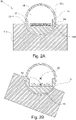
- Fig. 2 shows a transport device 10 according to the invention, comprising a first section 11a of an outer container.
- the first section comprises a shell on the inside having the shape of a spherical cap 12a, with an inner diameter and an opening.
- the opening 13 of the spherical cap faces upwards.
- the device further comprises an inner container 14 having an upper section 15b a lower section 15a and an inner hollow volume 16 defined thereby.
- the lower section has a spherical shape on the outside, the outer diameter of which is smaller than the inner diameter of the spherical cap 13.
- the inner container is suitable to be arranged in the spherical cap of the outer container in a freely pivotable fashion.
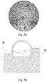
- Fig. 7A shows the dimensions that are necessary to define the spherical cap of the transport device according to the present invention, as shown in grey shade.
- the shell on the inside of the first section of the outer container, with its spherical cap-like shape, has a three dimensional concave form (i.e., is curved inward).
- the lower section of the inner container, with its spherical shape on the outside, has a three dimensional convex form (i.e., is curved outward).
- spherical cap as used herein, is used interchangeably with the terms “spherical dome”, or “spherical segment”, and relate to a portion of a sphere cut off by a plane. If the plane passes through the center of the sphere, so that the height of the cap (h) is equal to the radius (r) of the sphere, the spherical cap is called a hemisphere. In such case, the angle ⁇ would assume 90°. See Fig. 7A for an explanation.
- hydrophobic relates to molecules or other molecular entities that are repelled from water molecules. They are nonpolar and, thus tend to be not dissolved in water but prefer other neutral molecules and nonpolar solvents. Hydrophobic surfaces have the ability to repel water. Generally, the hydrophobicity of a surface can be measured by the contact angle between the droplets of water with the surface itself. The water droplets on the hydrophobic surface will flow very easily and retain its spherical shape with contact angle more than 90 degrees [8], while superhydrophobic materials possess large contact angles above 150 degrees and difficult to wet. Examples of hydrophobic molecules include the alkanes, oils, fats, and greasy substances in general.
- Archimedes' principle states that the upward buoyant force that is exerted on a body immersed in a fluid, whether fully or partially submerged, is equal to the weight of the fluid that the body displaces and acts in the upward direction at the center of mass of the displaced fluid. Thus, if the specific weight of an object is lower than the specific weight of water, the object will float on the water surface.
- the inner container floats on said liquid, hence avoiding any friction between the inner container and the inner surface of the shell on the inside of the first section of the outer container. This enables the inner container to always maintain, or reestablish, an upright position even when the outer container is tilted.
- the outer container is maximally half filled with said liquid.
- the filling level of said liquid ensures that the inner container floats within said liquid.
- said liquid serves to exert buoyancy and does not serve as a lubricant. Since there is no direct contact between the surface of the inner container and the surface of the shell on the inside of the second section of the outer container, there is also no friction in said areas. This enables the inner container to always maintain, or reestablish, an upright position even when the outer container is tilted.
- half filled with liquid means that the liquid, once the inner container is disposed in the outer container, reaches only to the equator of the inner container.
- the outer container is maximally filled by 25 %, preferably maximally 15 %, more preferably maximally 10%, more preferably maximally 5 %, more preferably maximally 2 % filled with water,.
- the liquid once the inner container is disposed in the outer container, reaches maximally up to a height of 25, 15, 10, 5, or 2 % of the inner container.
- a lubricant is disposed in said interstice. Said lubricant as well reduces the friction between the inner container and the inner surface of the shell on the inside of the first section of the outer container. This enables the inner container to always maintain, or reestablish, an upright position even when the outer container is tilted.
- At least two balls or ball bearings are disposed in said interstice.
- the balls as well reduce the friction between the inner container and the inner surface of the shell on the inside of the first section of the outer container. This enables the inner container to always maintain, or reestablish, an upright position even when the outer container is tilted.
- thermal insulator refers to and object or material that provides the reduction of heat transfer, i.e. the transfer of thermal energy between objects of differing temperature, between objects in thermal contact or in range of radiative influence. Thermal insulation can be achieved with specially engineered methods or processes, as well as with suitable object shapes and materials.
- Said spherical cap has essentially the same radius as the spherical cap comprised in the first section of the outer container.
- the two hemispherical caps form a sphere.
- the inner container is fully protected when the outer container is not just tilted a couple of degrees but either 90° or 180° degrees, ultimately requiring that the inner section can rotate 360° and is always upright.
- the heating unit and/or the cooling unit can comprise a thermal pack, comprising, e.g., ice or dry ice, or so-called fluid elements, as produced by delta T GmbH, Fernwald.
- the heating unit and/or the cooling unit can also comprise a thermoelectric element, e.g., a Peltier element.
- the temperature sensor and/or recorder can be any suitable sensor and/or recorder (also called “logger") that is available in the art. It is preferably battery driven and covers a temperature range of between - 50 and + 50 °C.
- the acceleration sensor and/or recorder can be any suitable sensor and/or recorder (also called “logger") that is available in the art.
- Such acceleration sensors and/or recorders are for example built in most mobile telecommunication devices available in the art.
- the identifiable tag or label can be any tag or label that provides a digital signature readable by a suitable device.
- Such tag or label can be a barcode or QR code that can be identified with a suitable optical reader, but can also be a tag or label that can be read out by radio-frequency identification (RFID) or near field communication (NFC).
- RFID radio-frequency identification
- NFC near field communication
- the mechanical actuator can battery-driven and can be a mechanical rotor with an eccentric load or a linear motor moving a load back and forth in a continuous pre-programmed way or remotely controlled.
- the payload can be any payload requiring upright or stabilized shipment.
- the multiwell plates or microtiter plates or microfluidic chips or cell and tissue culturing dishes are plates that contain liquid/medium and comprise one or more cell, cell culture, microtissue, 3D tissue, spheroidal tissue, composite tissue, tissue sample, tissue slice, or the like.
- the outer container and/or the inner container comprise a material selected from the group consisting of
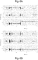
- Fig. 6A and 6B show data of a transatlantic flight cargo from Switzerland to US.
- the acceleration data of the box reveals that the box has been turned over and placed upside down after about 30 hours of travel.
- the inner floating sphere remained upside.
- the data in Figure 6B shows a constant value of -1 for the acceleration in z-direction.
- Fig. 6C presents data from a ground shipment simulation over 25 hours. Z-Acceleration data of the inside of the goods compartment is presented. Above the graph, the orientation of the outer box and transportation of the box is depicted. Tilting and flipping of the box was well compensated and the inner sphere remained in an upright position independent of transportation and orientation of the outside box.
Landscapes
- Health & Medical Sciences (AREA)
- Chemical & Material Sciences (AREA)
- Life Sciences & Earth Sciences (AREA)
- Engineering & Computer Science (AREA)
- Wood Science & Technology (AREA)
- Zoology (AREA)
- Organic Chemistry (AREA)
- Bioinformatics & Cheminformatics (AREA)
- Clinical Laboratory Science (AREA)
- General Health & Medical Sciences (AREA)
- Chemical Kinetics & Catalysis (AREA)
- Biotechnology (AREA)
- Biomedical Technology (AREA)
- Microbiology (AREA)
- Sustainable Development (AREA)
- Biochemistry (AREA)
- General Engineering & Computer Science (AREA)
- Genetics & Genomics (AREA)
- Mechanical Engineering (AREA)
- Environmental Sciences (AREA)
- Dentistry (AREA)
- Analytical Chemistry (AREA)
- Dispersion Chemistry (AREA)
- Molecular Biology (AREA)
- Details Of Rigid Or Semi-Rigid Containers (AREA)
- Apparatus Associated With Microorganisms And Enzymes (AREA)
- Devices For Use In Laboratory Experiments (AREA)
- Automatic Analysis And Handling Materials Therefor (AREA)
- Supplying Of Containers To The Packaging Station (AREA)
- Auxiliary Devices For And Details Of Packaging Control (AREA)
- Closures For Containers (AREA)
Description
- The present application relates to a transport device with an inner container.
- Very often delicate goods are shipped to customers by usual mail services. In the course of such shipping, the respective transport boxes are often tilted, which may affect the goods transported therein.
- One example for such delicate goods are biological specimen, like e.g. tissue samples, or microtissues. These are often stored and shipped in microwell plates often sealed by a sealing film or cover. When the surrounding transport box is tilted during transport, the microwell plate is tilted as well, and the culture liquid and the biological specimen fall out of the bottom of the microwell and move towards the top of the plate. Under unfavorable conditions the biological specimen can come into contact with the sealing film or cover, can attach to it or can be trapped between the sealing film and the upper wall of the microwell. Trapping or the contact with the sealing film can have adverse effects on the microtissue.
- When the surrounding transport box is turned back into a horizontal position, the biological specimen may not return into the central groove, while the culture liquid does. As a consequence, the biological specimen may experience harm, or may even die.
- If the biological specimen is attached to the bottom, tilting may move the liquid to the upper part of the well separating it from the biological specimen. This can lead to drying out of the biological specimen, nutrient depletion, and finally death.
- In another example the goods are microplates, microfluidic chips or cell culturing dishes filled with a defined amount of liquid with or without biological specimen. If such good are only covered by a lid or the sealing is not complete liquid tight (in some cases by purpose to ensure gas exchange), tilting will lead to spillage or the liquid running out of its well or channels.
- For other delicate goods to be shipped similar considerations apply when the transport box is tilted.
-
WO 2011/147384 A2 refers to a device for maintaining a stable position of a container, containing a casing having an outer cubic surface and an inner spherical surface and a carrier of the container equipped with steering devices, wherein the container carrier is in the form of a spherical cap and is equipped with six steering devices, which are sliding elements; and the bottom of the spherical cap of the container carrier is provided with a stabilizing weight. -
NL 1 033 089 C2 -
FR 585 827 A -
GB 2494651 A - The outer container may be any shape, but must not inhibit rotation of the inner container or allow movement by more than about 20cm.
-
US 2011/281352 A1 refers to a device according to the generic part ofclaim 1. - It is hence one object of the present invention to provide a transport device that protects the transported goods from negative effects when the device is tilted during transport.
- It is one further object of the present invention to provide a transport device that allows safe shipment of delicate goods, including biological specimen and not fully sealed devices, in which tilting may lead to liquid spillage or drainage.
- These and further objects are met with a transport device according to the independent claim of the present invention. The dependent claims are related to specific embodiments.
- It is important to understand that most figures show a two-dimensional cross section of a transport device according to the invention, which is a three-dimensional object. Hence, considerations and discussions made with regard to the figures apply to a three-dimensional obj ect.
-
Fig. 1 is provided to demonstrate a fundamental problem that occurs when microwell plates are tilted. -
Fig. 1A shows a close-up of amicrowell plate 30 with one well 31 shown. The well is sealed by asealing film 32 and has a central groove where abiological specimen 34, e.g., a microtissue, is disposed, and covered by culture liquid 35. -
Fig. 1B shows what happens when the microwell plate is tilted. The culture liquid and the biological specimen fall out of the central groove (see arrow), and under unfavorable conditions the biological specimen can be trapped between the sealing film and the upper wall of the well. Even though such film can be made from a biocompatible material, the microtissue might either adhere thereto or be squeezed in the angle formed by the film and the well's wall. When the microwell plate is turned back into a horizontal position, the biological specimen may not return into the central groove, while the culture liquid does. As a consequence, the biological specimen may experience harm, or may even die. It has to be noted that such problem mostly applies to biological specimens that are not attached to the bottom. -
Fig. 1C shows what can happen with biological specimens that are attached or adhere to the culturing in case the microwell plate is tilted. In such case, the culturing liquid moves to the top of the well, leaving the biological specimen dry at the bottom of the well. - Another problem might occur when a sealing film, or more generally a lid or cover, is chosen which is not totally liquid tight, but just protects from spillage or ensures oxygen supply (having small holes for example). Prolonged tilting would lead to complete drainage of the well. As a consequence, the biological specimen may experience harm, or may even die.
-
Fig. 2 shows atransport device 10 according to the invention, comprising afirst section 11a of an outer container. The first section comprises a shell on the inside having the shape of aspherical cap 12a, with an inner diameter and an opening. The opening 13 of the spherical cap faces upwards. The device further comprises aninner container 14 having anupper section 15b alower section 15a and an innerhollow volume 16 defined thereby. The lower section has a spherical shape on the outside, the outer diameter of which is smaller than the inner diameter of thespherical cap 13. The inner container is suitable to be arranged in the spherical cap of the outer container in a freely pivotable fashion. The inner container is capable of accommodating apayload 17, namely a microtiter plate that accommodates microtissues. The inner container is designed in such way, or a counterweight is arranged in the inner container in such way, that the center ofgravity 22 of the inner container, when containing a payload, is arranged eccentrically below the inner container'srotational center 23. Further, aninterstice 18 is defined between the inner diameter of the spherical cap of the first section of the outer container and the outer diameter of the spherical shape of the inner container. A volume ofliquid 19 is disposed in said interstice, which reaches maximally to a height of 2,3 % of the inner container. It can clearly bee seen that the inner container floats on the volume of liquid. In such way, sufficient degrees of freedom are provided for the inner container to float. Likewise, friction between the surfaces is reduced to a minimum. - In
Fig. 2A , the device is shown in a normal position, while inFig. 2B the device is tilted by an angle of about 20°. It is clearly visible that despite the fact that the outer container is tilted, the inner container adopts an upright position. -
Figs 2C , D, E and F show further embodiments.Fig 2C and D show an embodiment in which the center of gravity of the inner container has a lateral offset, as, e.g., caused by aspecific counterweight 36, arranged below the inner container's center, but offset of the vertical axis. In this embodiment, the inner container permanently adopts a defined tilted angle when in resting position, independent of the orientation of the outer container (Fig. 2C : Horizontal,Fig. 2D : tilted). In such way, a gravity-driven flow in a microwell plate or a microfluidic chip comprised in the inner container can be for example be established. -
Fig. 2E shows an embodiment in which the center of gravity of the inner container can be changed, e.g., caused by aspecific counterweight 36 that is continuously agitated in a lateral fashion, by a suitablelinear actuator 37. In this embodiment, the inner container is subjected to a rocking movement, independent of the orientation of the outer container. In such way, liquids and/or biological specimen comprised in the inner container can be agitated. -
Fig. 2F shows an embodiment in which the center of gravity of the inner container can be changed, e.g., caused by aspecific counterweight 36 that is continuously agitated in a circular fashion, by a suitablecircular actuator 38. In this embodiment, the inner container is subjected to a circular rocking movement, independent of the orientation of the outer container. In such way, liquids and/or biological specimen comprised in the inner container can be agitated. -
Fig. 3A shows a similar transport device according to the invention, wherein further the outer container comprises asecond section 11b comprising a shell on the inside having the shape of aspherical cap 12b, with an inner diameter and an opening, wherein the opening of the spherical cap faces downwards. -
Fig. 3B shows a similar transport device according to an aspect, wherein threeball bearings 21 are disposed in theinterstice 18. The width of theinterstice 18 depends on the length ball bearings extend into the interstice (see arrow). -
Figs. 4A-C show three dimensional renderings of a transport device according to the invention. The twosections sections Fig 4A also shows a box in the center, which is the actual transported good in the present example. The box can comprise, e.g., biological specimen. -
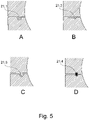
Figs. 5A-D show different possibilities to connect the twosections - The tongue can be bigger than the groove, so that it needs to be pressed in to ensure tightness. The grove can also be left away so that the tongue has to be deformed for tightness.
-
Fig. 6 shows acceleration data measured from test shipments of a prototype using the floating sphere concept. -
Fig. 7A shows the dimensions that are necessary to define the spherical cap of the transport device according to the present invention, as shown in grey shade. - The term "spherical cap", as used herein, is used interchangeably with the terms "spherical dome", or "spherical segment", and relate to a portion of a sphere cut off by a plane. If the plane passes through the center of the sphere, so that the height of the cap (h) is equal to the radius (r) of the sphere, the spherical cap is called a hemisphere. In such case, the angle θ would assume 90°. In most cases, θ will be in the range of 45 - 89 °, so that the inner container can easily be deposited in, or removed from, the shell on the inside of the first section of the outer container.
-
Fig. 7B shows two alternatives, namely one (left side) where θ2 is smaller than 90 ° (hence the inner container can easily be deposited in, or removed from, the shell on the inside of the first section of the outer container), and one (right side) where θ2 is greater than 90 ° (hence the inner container rests more securely in the shell on the inside of the first section of the outer container, but can less easily be deposited therein, or removed therefrom). - Before the invention is described in detail, it is to be understood that this invention is not limited to the particular component parts of the devices described or process steps of the methods described as such devices and methods may vary. It is also to be understood that the terminology used herein is for purposes of describing particular embodiments only, and is not intended to be limiting. It must be noted that, as used in the specification and the appended claims, the singular forms "a", "an", and "the" include singular and/or plural referents unless the context clearly dictates otherwise. It is moreover to be understood that, in case parameter ranges are given which are delimited by numeric values, the ranges are deemed to include these limitation values.
- It is further to be understood that embodiments disclosed herein are not meant to be understood as individual embodiments which would not relate to one another. Features discussed with one embodiment are meant to be disclosed also in connection with other embodiments shown herein. If, in one case, a specific feature is not disclosed with one embodiment, but with another, the skilled person would understand that does not necessarily mean that said feature is not meant to be disclosed with said other embodiment. The skilled person would understand that it is the gist of this application to disclose said feature also for the other embodiment, but that just for purposes of clarity and to keep the specification in a manageable volume this has not been done.
- Furthermore, the content of the prior art documents referred to herein is incorporated by reference. This refers, particularly, for prior art documents that disclose standard or routine methods. In that case, the incorporation by reference has mainly the purpose to provide sufficient enabling disclosure, and avoid lengthy repetitions.
- According to a first aspect of the invention, a transport device is provided, comprising
- a) a first section of an outer container comprising a shell on the inside having the shape of a spherical cap, with an inner diameter and an opening, wherein the opening of the spherical cap faces upwards,
- b) an inner container having an upper section a lower section and an inner hollow volume defined thereby, wherein at least the lower section has a spherical shape on the outside, the outer diameter of which is smaller than the inner diameter of the spherical cap of the outer container,
- c) the inner container being suitable to be arranged in the spherical cap of the outer container in a freely pivotable fashion.
- d) the inner container being capable of accommodating a payload.
- The inner container is designed in such way, or a counterweight is arranged in the inner container in such way, that the center of gravity of the inner container, is arranged eccentrically below the inner container's rotational center, wherein an interstice is defined between the inner diameter of the spherical cap of the first section of the outer container and the outer diameter of the spherical shape of the inner container, wherein a volume of liquid is disposed in said interstice, wherein the inner container has a lower specific weight than said liquid, and the inner container floats on said liquid.
- The shell on the inside of the first section of the outer container, with its spherical cap-like shape, has a three dimensional concave form (i.e., is curved inward). The lower section of the inner container, with its spherical shape on the outside, has a three dimensional convex form (i.e., is curved outward).
- The term "spherical cap", as used herein, is used interchangeably with the terms "spherical dome", or "spherical segment", and relate to a portion of a sphere cut off by a plane. If the plane passes through the center of the sphere, so that the height of the cap (h) is equal to the radius (r) of the sphere, the spherical cap is called a hemisphere. In such case, the angle θ would assume 90°. See
Fig. 7A for an explanation. - It has to be mentioned that high tolerances can be accepted as regards the spherical properties. The shells do not need to be "super strictly" spherical. The general shape needs to be spherical, but there can be irregularities, like notches or recesses, which allow holding the sphere or that may have been introduced by the fabrication process. The size of them should be as small as the general function of free rotation and upright orientation of the inner container is always given.
- The shell on the inside of the first section of the outer container thus serves as a bed for the inner container with its spherical shape. In most cases, θ will be in the range of 45 - 89 °, so that the inner container can easily be deposited in, or removed from, the shell on the inside of the first section of the outer container.
- In one aspect, the shell on the inside of the first section of the outer container acts like a socket in a ball and socket joint, while the inner container, with its spherical shape on the outside, acts like a ball which rests in said socket.
- According to the invention, the inner container is designed in such way, or a counterweight is arranged in the inner container in such way, that the center of gravity (22) of the inner container, when containing a payload, is arranged eccentrically below the inner container's rotational center (23).
- The center of gravity of the inner container is arranged eccentrically, and below the inner container's rotational center. In such way, because the inner container is freely movable in the shell on the inside of the outer container, it is, by gravity, capable of maintaining, or reestablishing, an upright position even when the outer container is tilted.
- See, in this regard
Figs 2 C - E , which show variables of this embodiment, in which (a) the center of gravity of the inner container has a lateral offset, so that the inner container adopts a defined tilted angle when in resting position, independent of the orientation of the outer container), or (b) the center of gravity of the inner container is periodically moved in a lateral or circular fashion using a suitable actuator, so that the payload is continuously agitated. - According to the invention, a volume of liquid is disposed in said interstice. Preferably, said liquid is hydrophilic, more preferably said liquid is water.
- The term "hydrophilic", as used herein, relates to molecules or other molecular entities that are attracted to water molecules and tend to be dissolved by water. They are typically chargepolarized and capable of hydrogen bonding. Hydrophilic liquids comprise such polar molecules and are thus also capable of hydrogen bonding. This especially applies to water, but also to (low) alcohols. Water (H2O) is a polar inorganic compound that is at room temperature a tasteless and odorless liquid. Water molecules form hydrogen bonds with each other and are strongly polar. Alcohols comprise hydroxyl groups that are polar and therefore hydrophilic but also comprise a carbon chain portion that is non-polar, i.e. hydrophobic. The alcohol molecule increasingly becomes overall more hydrophobic as the carbon chain becomes longer. Examples of hydrophilic liquids include, but are not limited to, water, alcohols, ammonia, some amides such as urea and some carboxylic acids such as acetic acid.
- According to a further embodiment of the invention, the surface of the inner container and/or the outer container is hydrophobic.
- The term "hydrophobic", as used herein, relates to molecules or other molecular entities that are repelled from water molecules. They are nonpolar and, thus tend to be not dissolved in water but prefer other neutral molecules and nonpolar solvents. Hydrophobic surfaces have the ability to repel water. Generally, the hydrophobicity of a surface can be measured by the contact angle between the droplets of water with the surface itself. The water droplets on the hydrophobic surface will flow very easily and retain its spherical shape with contact angle more than 90 degrees [8], while superhydrophobic materials possess large contact angles above 150 degrees and difficult to wet. Examples of hydrophobic molecules include the alkanes, oils, fats, and greasy substances in general.
- According to the invention, the inner container has a lower specific weight than said liquid.
- The term "specific weight", as used herein, is defined as weight per unit volume of a material. The symbol of specific weight is γ (the Greek letter Gamma). The SI unit for specific weight is [N/m3]. Specific weight can be expressed as

- γ = specific weight (N/m3]
- ρ = density [kg/m3]
- ag = acceleration of gravity (9.81 [m/s2], under normal conditions)
- The following table shows the specific weights of some common materials.
Product Specific weight [kN/m3] Air 0,011772 Aluminum 27 Copper 89 Ethyl Alcohol 7.74 Seawater 10.03 Stainless Steel 78 - 80 Water 9.81 extruded polystyrene foam 0,4905 expanded polystyrene (EPS) 0,0108 - 0,0314 expanded polypropylene (EPP) 0,1196 - 0,1177 wood 4,6107 - 10,3986 Thermoplasts 7,848 - 21,582 Teflon 21,582 - According to the invention, the lower specific weight of the inner container creates buoyancy of the inner container.
- Archimedes' principle states that the upward buoyant force that is exerted on a body immersed in a fluid, whether fully or partially submerged, is equal to the weight of the fluid that the body displaces and acts in the upward direction at the center of mass of the displaced fluid. Thus, if the specific weight of an object is lower than the specific weight of water, the object will float on the water surface.
- The inner container floats on said liquid, hence avoiding any friction between the inner container and the inner surface of the shell on the inside of the first section of the outer container. This enables the inner container to always maintain, or reestablish, an upright position even when the outer container is tilted.
- According to an embodiment of the invention, the outer container is maximally half filled with said liquid.
- In this embodiment, the filling level of said liquid ensures that the inner container floats within said liquid. Thus, said liquid serves to exert buoyancy and does not serve as a lubricant. Since there is no direct contact between the surface of the inner container and the surface of the shell on the inside of the second section of the outer container, there is also no friction in said areas. This enables the inner container to always maintain, or reestablish, an upright position even when the outer container is tilted.
- The term "half filled with liquid" means that the liquid, once the inner container is disposed in the outer container, reaches only to the equator of the inner container.
- Preferably, the outer container is maximally filled by 25 %, preferably maximally 15 %, more preferably maximally 10%, more preferably maximally 5 %, more preferably maximally 2 % filled with water,. In all the cases, the liquid, once the inner container is disposed in the outer container, reaches maximally up to a height of 25, 15, 10, 5, or 2 % of the inner container.
- According to an aspect not forming part of the claimed invention, a lubricant is disposed in said interstice. Said lubricant as well reduces the friction between the inner container and the inner surface of the shell on the inside of the first section of the outer container. This enables the inner container to always maintain, or reestablish, an upright position even when the outer container is tilted.
- According to a further aspect not forming part of the claimed invention, at least two balls or ball bearings are disposed in said interstice.
- The balls as well reduce the friction between the inner container and the inner surface of the shell on the inside of the first section of the outer container. This enables the inner container to always maintain, or reestablish, an upright position even when the outer container is tilted.
- According to a further embodiment of the invention, at least
- a) the inner surface of the shell on the inside of the first section of the outer container, and
- b) the outer surface of the lower section of the inner container
- The term "low friction coefficient" relates to static friction (µs). Preferably, the coatings that are used, when acting with one another, establish a friction coefficient of < 0.2 µs or less. The said condition applies, for example, to the following material pairs:
Materials and Material Combinations Static Frictional Coefficient (µs ) Bronze Steel Bronze Cast Iron 0.22 Bronze - sintered Steel Carbon (hard) Carbon 0.16 Carbon Steel 0.14 Copper-Lead alloy Steel 0.22 Diamond Diamond 0.1 Diamond Metal 0.1 - 0.15 Graphite Steel 0.1 Graphite Graphite 0.1 Nylon Nylon 0.15 - 0.25 Polythene Steel 0.2 Sapphire Sapphire 0.2 Polytetrafluoro ethylene (PTFE) PTFE 0.04 PTFE Steel 0.05 Tungsten Carbide Tungsten Carbide 0.2 - 0.25 Wax Wax 0.25 - In such way, the friction between the inner container and the inner surface of the shell on the inside of the first section of the outer container is reduced. This enables the inner container to always maintain, or reestablish, an upright position even when the outer container is tilted.
- The width of the interstice can depend on the material that is disposed between the surfaces of the shell on the inside of the first section of the outer container and the lower section of the inner container.
- According to one embodiment, the width of the interstice in which the volume of liquid is applied is in the range of ≥ 2 mm and ≤ 15 mm, so as to allow floating of the inner container. In such way, sufficient degrees of freedom are provided for the inner container to float. Likewise, friction between the surfaces is reduced to a minimum. Further, such relatively wide interstices make the production of the inner- and outer container more easy, because higher tolerances are admissible.
- In this embodiment, due to the large width of the interstice, there is no direct contact between the surface of the inner container and the surface of the shell on the inside of the first and the second section of the outer container, therefore there is no friction between the inner and the outer container. This enables the inner container to always maintain, or reestablish, an upright position even when the outer container is tilted.
- In one aspect, the width of the interstice in which a lubricant is applied is almost infinitesimally small, with the usual tolerances, so that the two surfaces are only separated from one another by a thin film of lubricant. Generally, the use of a lubricant requires that the width of the interstice is smaller than if a volume of liquid would be applied. This again makes the manufacturing process more demanding. In one embodiment, the interstice is not wider than 2 mm.
- In one aspect, which comprises balls or ball bearings, the width of the interstice depends on the length the balls or ball bearings extend into the interstice (see e.g.
Fig. 3B ), plus tolerances if applicable. - In one embodiment, which comprises surfaces that establish a low friction coefficient, the width of the interstice can be infinitesimally small (with the usual tolerance), so that the two surfaces are in direct contact to one another. Generally, such embodiment makes the manufacturing process highly demanding.
- In one embodiment, the width of the interstice is not wider than 2 mm, preferably not wider than 1,5 mm, most preferably not wider than 1 mm.
- According to a further embodiment of the invention, the inner container and/or the outer container comprises a material that is a thermal insulator.
- The term "thermal insulator", as used herein, refers to and object or material that provides the reduction of heat transfer, i.e. the transfer of thermal energy between objects of differing temperature, between objects in thermal contact or in range of radiative influence. Thermal insulation can be achieved with specially engineered methods or processes, as well as with suitable object shapes and materials.
- The insulating capability of a material is measured as the inverse of thermal conductivity (k). Low thermal conductivity is equivalent to high insulating capability (Resistance value). Thermal conductivity k is measured in watts-per-meter per kelvin (W·m-1·K-1 or W/m/K). Thermal conductivity depends on the material and for fluids, its temperature and pressure. For comparison purposes, conductivity under standard conditions (20 °C at 1 atm) is commonly used. For some materials, thermal conductivity may also depend upon the direction of heat transfer.
- The following table shows thermal conductivity for some materials at atmospheric pressure and around 293 K (20 °C).
Material Thermal conductivity [W·m -1 ·K -1 ] Silica aerogel 0.02 Polyurethane foam 0.03 Expanded polystyrene 0.033-0.046 Fiberglass or foam-glass 0.045 Alcohols, oils 0.100 Snow (dry) 0.050-0.250 Acrylic glass (Plexiglas V045i) 0.170-0.200 Teflon 0.250 Water 0.5918 Marble 2.070-2.940 Manganese 7.810 Alumina 30 Aluminium 237 Copper (pure) 401 Diamond 1,000-2200 Boron arsenide 1,300 - According to a further embodiment of the invention, the outer container further comprises a second section comprising a shell on the inside having the shape of a spherical cap, with an inner diameter and an opening, wherein the opening of the spherical cap faces downwards. This section acts as a lid for the container, and provides insulation and protection.
- Said spherical cap has essentially the same radius as the spherical cap comprised in the first section of the outer container. When the second section of the outer container is arranged on top of the first section, the two hemispherical caps form a sphere. In such embodiment, the inner container is fully protected when the outer container is not just tilted a couple of degrees but either 90° or 180° degrees, ultimately requiring that the inner section can rotate 360° and is always upright.
- According to a further embodiment of the invention, device further comprises at least one selected from the group consisting of
- a) a heating unit,
- b) a cooling unit
- c) a temperature sensor and/or recorder,
- d) an acceleration sensor and/or recorder,
- f) a geolocalization sensor and/or recorder,
- g) an identifiable tag or label
- h) mechanical actuator for moving the center of gravity with respect to the center of the sphere
- The heating unit and/or the cooling unit can comprise a thermal pack, comprising, e.g., ice or dry ice, or so-called fluid elements, as produced by delta T GmbH, Fernwald. The heating unit and/or the cooling unit can also comprise a thermoelectric element, e.g., a Peltier element.
- The temperature sensor and/or recorder can be any suitable sensor and/or recorder (also called "logger") that is available in the art. It is preferably battery driven and covers a temperature range of between - 50 and + 50 °C.
- The acceleration sensor and/or recorder can be any suitable sensor and/or recorder (also called "logger") that is available in the art. Such acceleration sensors and/or recorders are for example built in most mobile telecommunication devices available in the art.
- The geolocalization sensor and/or recorder can be any suitable sensor and/or recorder (also called "logger") that is available in the art. Such geolocalization sensors and/or recorders are for example built in most mobile telecommunication devices available in the art.
- The identifiable tag or label can be any tag or label that provides a digital signature readable by a suitable device. Such tag or label can be a barcode or QR code that can be identified with a suitable optical reader, but can also be a tag or label that can be read out by radio-frequency identification (RFID) or near field communication (NFC).
- The mechanical actuator can battery-driven and can be a mechanical rotor with an eccentric load or a linear motor moving a load back and forth in a continuous pre-programmed way or remotely controlled.
- According to a further embodiment of the invention, the payload double acts as a counterweight. This facilitates the entire production process.
- According to a further embodiment of the invention the payload is at least one selected from the group consisting of
- one or more multiwell plates or microtiter plates, or a container comprising one or more such plates
- a microfluidic system or microfluidic chips, and/or
- cell culturing dishes and systems
- In general, the payload can be any payload requiring upright or stabilized shipment.
- Preferably, the multiwell plates or microtiter plates or microfluidic chips or cell and tissue culturing dishes are plates that contain liquid/medium and comprise one or more cell, cell culture, microtissue, 3D tissue, spheroidal tissue, composite tissue, tissue sample, tissue slice, or the like.
- According to a further embodiment of the invention, the outer container and/or the inner container comprise a material selected from the group consisting of
- extruded polystyrene foam
- expanded polystyrene (EPS)
- expanded polypropylene (EPP)
- metal
- wood
- thermoplasts
- friction-minimizing material such as teflon
- While the invention has been illustrated and described in detail in the drawings and foregoing description, such illustration and description are to be considered illustrative or exemplary and not restrictive; the invention is not limited to the disclosed embodiments. Other variations to the disclosed embodiments can be understood and effected by those skilled in the art in practicing the claimed invention, from a study of the drawings, the disclosure, and the appended claims. In the claims, the word "comprising" does not exclude other elements or steps, and the indefinite article "a" or "an" does not exclude a plurality. The mere fact that certain measures are recited in mutually different dependent claims does not indicate that a combination of these measures cannot be used to advantage. Any reference signs in the claims should not be construed as limiting the scope.
- A prototype of the transport device was developed and tested. The device was packed in a usual transport box which remained unopened the whole time.
- Both sections of the outer and inner container were closed and sealed water-tight with silicone. Water was filled between the two shells enabling free rotation of the inner shell with respect to the outer shell. To record the orientation of the shells, one accelerometer was placed inside the box together with the shipped goods and one accelerometer was placed on the outside of the box. Upright orientation equals to a value of -1 g in z-direction and a value of 0 in x and y direction.
-
Fig. 6A and 6B show data of a transatlantic flight cargo from Switzerland to US. The acceleration data of the box reveals that the box has been turned over and placed upside down after about 30 hours of travel. The inner floating sphere remained upside. The data inFigure 6B shows a constant value of -1 for the acceleration in z-direction. -
Fig. 6C presents data from a ground shipment simulation over 25 hours. Z-Acceleration data of the inside of the goods compartment is presented. Above the graph, the orientation of the outer box and transportation of the box is depicted. Tilting and flipping of the box was well compensated and the inner sphere remained in an upright position independent of transportation and orientation of the outside box. -
- 10 transport device
- 11 outer container
- 11a first section of outer container
- 11b second section of outer container
- 12a shell on the inside of outer container having the shape of a spherical cap
- 13 opening of
shell 12a - 14 inner container
- 15b upper section of inner container
- 15a lower section of inner container
- 16 inner hollow volume of inner container
- 17 payload
- 18 interstice
- 19 liquid disposed in interstice
- 20 ball bearing
- 21.1, 21.2, 21.3 tongue-and-groove joints
- 21.4 O-ring
- 22 center of gravity of inner container
- 23 rotational center of inner container
- 30 microwell plate
- 31 well
- 32 sealing film
- 33 central groove
- 34 biological specimen
- 35 culture liquid
- 36 counterweight
- 37 linear actuator
- 38 circular actuator
Claims (11)
- A Transport device (10), comprisinga) a first section (11a) of an outer container (11) comprising a shell on the inside having the shape of a spherical cap (12a), with an inner diameter and an opening (13), wherein the opening of the spherical cap (12a) faces upwards,b) an inner container (14) having an upper section (15b) a lower section (15a) and an inner hollow volume (16) defined thereby, wherein at least the lower section (15a) has a spherical shape on the outside, the outer diameter of which is smaller than the inner diameter of the spherical cap (12a) of the outer container (11),c) the inner container (14) being suitable to be arranged in the spherical cap (12a) of the outer container (11) in a freely pivotable fashion,d) the inner container (14) capable of accommodating a payload (17),wherein the inner container (14) is designed in such way, or a counterweight is arranged in the inner container (14) in such way, that the center of gravity (22) of the inner container (14), is arranged eccentrically below the inner container's (14) rotational center (23),wherein an interstice (18) is defined between the inner diameter of the spherical cap (12a) of the first section (11a) of the outer container (11) and the outer diameter of the spherical shape of the inner container (14),wherein a volume of liquid (19) is disposed in said interstice (18),characterized in that the inner container (14) has a lower specific weight than said liquid (19),and the inner container (14) floats on said liquid (19).
- The Transport device (10) according to claim 1, wherein said liquid (19) is hydrophilic.
- The Transport device (10) according to claim 1 or 2, wherein said liquid (19) is water.
- The Transport device (10) according to any one of claims 1 to 3, wherein the surface of the inner container (14) and/or the outer container (11) is hydrophobic.
- The Transport device (10) according any one of claims 1 to 4, wherein the outer container (11) is maximally half filled with said liquid (19).
- The Transport device (10) according any one of the claims 1 to 5, wherein the width of the interstice (18) in which the volume of liquid is applied is in the range of ≥ 2 mm and ≤ 15 mm.
- The Transport device (10) according to any one of claims 1 to 6, wherein the inner container (14) and/or the outer container (11) comprises a material that is a thermal insulator.
- The Transport device (10) according to any one of claims 1 to 7, wherein the outer container (11) further comprises a second section (11b) comprising a shell on the inside having the shape of a spherical cap (12b), with an inner diameter and an opening, wherein the opening of the spherical cap faces downwards.
- The Transport device (10) according to any one of claims 1 to 8, which device (10) further comprises at least one selected from the group consisting of:a) a heating unit,b) a cooling unitc) a temperature sensor and/or recorder,e) an acceleration sensor and/or recorder,f) a geolocalization sensor and/or recorder,g) an identifiable tag or label, and/orh) a mechanical actuator moving the center of gravity with respect to the center of the sphere
- The Transport device (10) according to any one of claims 1 to 9, wherein the payload is at least one selected from the group consisting of• one or more multiwell plates or microtiter plates, or a container comprising one or more such plates• microfluidic system or microfluidic chips, and/or• cell culturing dishes and systems
- The Transport device (10) according to any one of the claims 1 to 10, wherein the outer container (11) and/or the inner container (14) comprise a material selected from the group consisting of• extruded polystyrene foam• expanded polystyrene (EPS)• expanded polypropylene (EPP)• metal• wood• thermoplasts• friction-minimizing material such as Teflon
Applications Claiming Priority (2)
| Application Number | Priority Date | Filing Date | Title |
|---|---|---|---|
| EP18192892.0A EP3620233A1 (en) | 2018-09-06 | 2018-09-06 | Transport device with an inner container |
| PCT/EP2019/073757 WO2020049123A1 (en) | 2018-09-06 | 2019-09-05 | Transport device with an inner container |
Publications (2)
| Publication Number | Publication Date |
|---|---|
| EP3846941A1 EP3846941A1 (en) | 2021-07-14 |
| EP3846941B1 true EP3846941B1 (en) | 2022-12-07 |
Family
ID=63524121
Family Applications (2)
| Application Number | Title | Priority Date | Filing Date |
|---|---|---|---|
| EP18192892.0A Withdrawn EP3620233A1 (en) | 2018-09-06 | 2018-09-06 | Transport device with an inner container |
| EP19762181.6A Active EP3846941B1 (en) | 2018-09-06 | 2019-09-05 | Transport device with an inner container |
Family Applications Before (1)
| Application Number | Title | Priority Date | Filing Date |
|---|---|---|---|
| EP18192892.0A Withdrawn EP3620233A1 (en) | 2018-09-06 | 2018-09-06 | Transport device with an inner container |
Country Status (11)
| Country | Link |
|---|---|
| US (1) | US11634260B2 (en) |
| EP (2) | EP3620233A1 (en) |
| JP (1) | JP7019866B2 (en) |
| KR (1) | KR102299949B1 (en) |
| CN (1) | CN112752611A (en) |
| CA (1) | CA3108037C (en) |
| DK (1) | DK3846941T3 (en) |
| ES (1) | ES2937010T3 (en) |
| MX (1) | MX2021002595A (en) |
| SG (1) | SG11202100774YA (en) |
| WO (1) | WO2020049123A1 (en) |
Families Citing this family (4)
| Publication number | Priority date | Publication date | Assignee | Title |
|---|---|---|---|---|
| US11268655B2 (en) | 2018-01-09 | 2022-03-08 | Cryoport, Inc. | Cryosphere |
| US12025276B2 (en) | 2018-01-09 | 2024-07-02 | Cryoport, Inc. | Cryosphere |
| CN114084476A (en) * | 2021-12-27 | 2022-02-25 | 四川大家医学检测有限公司 | Multi-functional clinical sample transport case |
| DE202023102353U1 (en) * | 2023-04-29 | 2023-05-16 | Genima Innovations Marketing Gmbh | Device for goods to be transported or stored in a stable position |
Family Cites Families (18)
| Publication number | Priority date | Publication date | Assignee | Title |
|---|---|---|---|---|
| FR585827A (en) * | 1924-07-23 | 1925-03-07 | Device for always keeping in a vertical position, one or more bottles or other objects | |
| US3024358A (en) * | 1958-04-15 | 1962-03-06 | Maxson Electronics Corp | Container |
| US4729413A (en) * | 1986-11-06 | 1988-03-08 | General Electric Company | Transport puck and method to fill caulking cartridges |
| US4919300A (en) * | 1989-03-31 | 1990-04-24 | Rj Lee Group, Inc. | Shipping device |
| JP3544710B2 (en) * | 1994-07-08 | 2004-07-21 | 信越半導体株式会社 | Semiconductor crystal container |
| US6673594B1 (en) * | 1998-09-29 | 2004-01-06 | Organ Recovery Systems | Apparatus and method for maintaining and/or restoring viability of organs |
| US6490880B1 (en) * | 2000-10-26 | 2002-12-10 | Islet Technology Inc. | Regulated organ containment shipping system using dual-layer preservation liquid |
| WO2003031065A1 (en) * | 2001-10-12 | 2003-04-17 | Becton, Dickinson And Company | Method and basket apparatus for transporting biological samples |
| DE10251650B4 (en) * | 2002-10-30 | 2005-05-04 | Schott Ag | Containers for storing and transporting delicate platelike articles and use of such |
| US7713686B2 (en) * | 2004-12-03 | 2010-05-11 | Biorep Technologies, Inc. | Organ preservation container and method |
| NL1033089C2 (en) * | 2006-12-19 | 2008-06-20 | Franciscus Johannes Van Wielen | Storage system comprising case with top and bottom trays, contains bottle holder provided in weighted semi sphere freely rotatable inside hollow ball |
| CN102036555A (en) * | 2007-04-26 | 2011-04-27 | 梅丁诺娃公司 | Transplant storage |
| CZ2010406A3 (en) * | 2010-05-25 | 2011-09-07 | Kobylka@Petr | Device to maintain container stable position |
| GB2494651A (en) * | 2011-09-13 | 2013-03-20 | Stephen Robinson | Inner Container Rotating In Outer Container to Keep Contents Upright |
| US20160090226A1 (en) | 2013-05-31 | 2016-03-31 | Wrh Walter Reist Holding Ag | Transportable packaging unit and method for producing said type of packaging unit |
| WO2015097700A1 (en) | 2013-12-26 | 2015-07-02 | Top-It-Up Ltd. | Floating device for growing fish and/or algae |
| CN205879652U (en) * | 2016-02-15 | 2017-01-11 | 复旦大学 | A box that takes precautions against earthquakes that is arranged in transportation to deposit cell sample that lives |
| CN205872862U (en) * | 2016-06-29 | 2017-01-11 | 郭子荣 | Biological sample collection conveyer |
-
2018
- 2018-09-06 EP EP18192892.0A patent/EP3620233A1/en not_active Withdrawn
-
2019
- 2019-09-05 ES ES19762181T patent/ES2937010T3/en active Active
- 2019-09-05 DK DK19762181.6T patent/DK3846941T3/en active
- 2019-09-05 CN CN201980057771.5A patent/CN112752611A/en active Pending
- 2019-09-05 US US17/273,961 patent/US11634260B2/en active Active
- 2019-09-05 SG SG11202100774YA patent/SG11202100774YA/en unknown
- 2019-09-05 KR KR1020217005856A patent/KR102299949B1/en active Active
- 2019-09-05 CA CA3108037A patent/CA3108037C/en active Active
- 2019-09-05 WO PCT/EP2019/073757 patent/WO2020049123A1/en not_active Ceased
- 2019-09-05 EP EP19762181.6A patent/EP3846941B1/en active Active
- 2019-09-05 MX MX2021002595A patent/MX2021002595A/en unknown
- 2019-09-05 JP JP2021512641A patent/JP7019866B2/en active Active
Also Published As
| Publication number | Publication date |
|---|---|
| EP3620233A1 (en) | 2020-03-11 |
| KR102299949B1 (en) | 2021-09-09 |
| MX2021002595A (en) | 2021-07-15 |
| US11634260B2 (en) | 2023-04-25 |
| CA3108037C (en) | 2021-11-30 |
| JP7019866B2 (en) | 2022-02-15 |
| KR20210042331A (en) | 2021-04-19 |
| ES2937010T3 (en) | 2023-03-23 |
| SG11202100774YA (en) | 2021-02-25 |
| CA3108037A1 (en) | 2020-03-12 |
| EP3846941A1 (en) | 2021-07-14 |
| WO2020049123A1 (en) | 2020-03-12 |
| JP2021528328A (en) | 2021-10-21 |
| DK3846941T3 (en) | 2023-03-06 |
| CN112752611A (en) | 2021-05-04 |
| US20210245945A1 (en) | 2021-08-12 |
Similar Documents
| Publication | Publication Date | Title |
|---|---|---|
| US11634260B2 (en) | Transport device with an inner container | |
| JP7154515B2 (en) | Apparatus for preserving and identifying biological samples in cryogenic conditions | |
| JP2019536434A5 (en) | ||
| US10295268B2 (en) | Phase change thermal-sink apparatus | |
| Ponomarenko et al. | A universal law for capillary rise in corners | |
| WO2018208576A1 (en) | Container for biological preservation at low temperature | |
| Dalbe et al. | Aggregation of frictional particles due to capillary attraction | |
| EP3721129B1 (en) | Cryosphere | |
| JP7715782B2 (en) | Structured Gas-Containing Surfaces | |
| EP2576384B1 (en) | Device for maintaining a stable position of a container | |
| CN109313109A (en) | A cryogenic biological storage container | |
| AU743336B2 (en) | In-container sachet | |
| US4236316A (en) | Vessel adaptable to the expansion and/or contraction of fluid therein | |
| WO2017083164A1 (en) | Dry shipping container | |
| WO2007056355A3 (en) | Devices and methods for culturing, preserving, transporting, storing, reconstituting and assaying cellular materials | |
| WO2019055448A1 (en) | Suspension culture devices and systems and related methods | |
| RU2021101574A (en) | TRANSPORT DEVICE WITH INNER CONTAINER | |
| Chen et al. | Film coating on a small sphere crossing an oil-water interface | |
| EP3990820B1 (en) | Cryosphere | |
| US20190008142A1 (en) | Automatic devices configured to perform a cryoprocedure on at least one biological sample carried by one or more carriers | |
| CN212566426U (en) | Self-leveling low-temperature transport barrel | |
| RU2263061C2 (en) | Vessel with neck | |
| CN109588407B (en) | Constant temperature cell transfer device without power supply | |
| Kim | Various Motions of Fluids | |
| HK40073800A (en) | Cryosphere |
Legal Events
| Date | Code | Title | Description |
|---|---|---|---|
| STAA | Information on the status of an ep patent application or granted ep patent |
Free format text: STATUS: UNKNOWN |
|
| STAA | Information on the status of an ep patent application or granted ep patent |
Free format text: STATUS: THE INTERNATIONAL PUBLICATION HAS BEEN MADE |
|
| PUAI | Public reference made under article 153(3) epc to a published international application that has entered the european phase |
Free format text: ORIGINAL CODE: 0009012 |
|
| STAA | Information on the status of an ep patent application or granted ep patent |
Free format text: STATUS: REQUEST FOR EXAMINATION WAS MADE |
|
| 17P | Request for examination filed |
Effective date: 20210311 |
|
| AK | Designated contracting states |
Kind code of ref document: A1 Designated state(s): AL AT BE BG CH CY CZ DE DK EE ES FI FR GB GR HR HU IE IS IT LI LT LU LV MC MK MT NL NO PL PT RO RS SE SI SK SM TR |
|
| DAV | Request for validation of the european patent (deleted) | ||
| DAX | Request for extension of the european patent (deleted) | ||
| GRAP | Despatch of communication of intention to grant a patent |
Free format text: ORIGINAL CODE: EPIDOSNIGR1 |
|
| STAA | Information on the status of an ep patent application or granted ep patent |
Free format text: STATUS: GRANT OF PATENT IS INTENDED |
|
| RIC1 | Information provided on ipc code assigned before grant |
Ipc: B65D 77/04 20060101ALN20220110BHEP Ipc: C12M 1/12 20060101ALI20220110BHEP Ipc: C12M 1/00 20060101ALI20220110BHEP Ipc: B65D 85/50 20060101ALI20220110BHEP Ipc: B65D 81/00 20060101ALI20220110BHEP Ipc: A01N 1/02 20060101ALI20220110BHEP Ipc: B01L 9/00 20060101AFI20220110BHEP |
|
| INTG | Intention to grant announced |
Effective date: 20220201 |
|
| GRAJ | Information related to disapproval of communication of intention to grant by the applicant or resumption of examination proceedings by the epo deleted |
Free format text: ORIGINAL CODE: EPIDOSDIGR1 |
|
| GRAL | Information related to payment of fee for publishing/printing deleted |
Free format text: ORIGINAL CODE: EPIDOSDIGR3 |
|
| GRAS | Grant fee paid |
Free format text: ORIGINAL CODE: EPIDOSNIGR3 |
|
| STAA | Information on the status of an ep patent application or granted ep patent |
Free format text: STATUS: REQUEST FOR EXAMINATION WAS MADE |
|
| GRAP | Despatch of communication of intention to grant a patent |
Free format text: ORIGINAL CODE: EPIDOSNIGR1 |
|
| STAA | Information on the status of an ep patent application or granted ep patent |
Free format text: STATUS: GRANT OF PATENT IS INTENDED |
|
| INTC | Intention to grant announced (deleted) | ||
| RIC1 | Information provided on ipc code assigned before grant |
Ipc: B65D 77/04 20060101ALN20220601BHEP Ipc: C12M 1/12 20060101ALI20220601BHEP Ipc: C12M 1/00 20060101ALI20220601BHEP Ipc: B65D 85/50 20060101ALI20220601BHEP Ipc: B65D 81/00 20060101ALI20220601BHEP Ipc: A01N 1/02 20060101ALI20220601BHEP Ipc: B01L 9/00 20060101AFI20220601BHEP |
|
| INTG | Intention to grant announced |
Effective date: 20220630 |
|
| GRAA | (expected) grant |
Free format text: ORIGINAL CODE: 0009210 |
|
| STAA | Information on the status of an ep patent application or granted ep patent |
Free format text: STATUS: THE PATENT HAS BEEN GRANTED |
|
| RIN1 | Information on inventor provided before grant (corrected) |
Inventor name: FLURI, DAVID Inventor name: MORITZ, WOLFGANG Inventor name: FREY, OLIVIER Inventor name: LICHTENBERG, JAN |
|
| AK | Designated contracting states |
Kind code of ref document: B1 Designated state(s): AL AT BE BG CH CY CZ DE DK EE ES FI FR GB GR HR HU IE IS IT LI LT LU LV MC MK MT NL NO PL PT RO RS SE SI SK SM TR |
|
| REG | Reference to a national code |
Ref country code: GB Ref legal event code: FG4D |
|
| REG | Reference to a national code |
Ref country code: CH Ref legal event code: EP Ref country code: AT Ref legal event code: REF Ref document number: 1535975 Country of ref document: AT Kind code of ref document: T Effective date: 20221215 |
|
| REG | Reference to a national code |
Ref country code: DE Ref legal event code: R096 Ref document number: 602019022909 Country of ref document: DE |
|
| REG | Reference to a national code |
Ref country code: IE Ref legal event code: FG4D |
|
| REG | Reference to a national code |
Ref country code: NL Ref legal event code: FP |
|
| REG | Reference to a national code |
Ref country code: SE Ref legal event code: TRGR |
|
| REG | Reference to a national code |
Ref country code: DK Ref legal event code: T3 Effective date: 20230228 |
|
| REG | Reference to a national code |
Ref country code: ES Ref legal event code: FG2A Ref document number: 2937010 Country of ref document: ES Kind code of ref document: T3 Effective date: 20230323 |
|
| REG | Reference to a national code |
Ref country code: LT Ref legal event code: MG9D |
|
| PG25 | Lapsed in a contracting state [announced via postgrant information from national office to epo] |
Ref country code: NO Free format text: LAPSE BECAUSE OF FAILURE TO SUBMIT A TRANSLATION OF THE DESCRIPTION OR TO PAY THE FEE WITHIN THE PRESCRIBED TIME-LIMIT Effective date: 20230307 Ref country code: LT Free format text: LAPSE BECAUSE OF FAILURE TO SUBMIT A TRANSLATION OF THE DESCRIPTION OR TO PAY THE FEE WITHIN THE PRESCRIBED TIME-LIMIT Effective date: 20221207 Ref country code: FI Free format text: LAPSE BECAUSE OF FAILURE TO SUBMIT A TRANSLATION OF THE DESCRIPTION OR TO PAY THE FEE WITHIN THE PRESCRIBED TIME-LIMIT Effective date: 20221207 |
|
| REG | Reference to a national code |
Ref country code: AT Ref legal event code: MK05 Ref document number: 1535975 Country of ref document: AT Kind code of ref document: T Effective date: 20221207 |
|
| PG25 | Lapsed in a contracting state [announced via postgrant information from national office to epo] |
Ref country code: RS Free format text: LAPSE BECAUSE OF FAILURE TO SUBMIT A TRANSLATION OF THE DESCRIPTION OR TO PAY THE FEE WITHIN THE PRESCRIBED TIME-LIMIT Effective date: 20221207 Ref country code: PL Free format text: LAPSE BECAUSE OF FAILURE TO SUBMIT A TRANSLATION OF THE DESCRIPTION OR TO PAY THE FEE WITHIN THE PRESCRIBED TIME-LIMIT Effective date: 20221207 Ref country code: LV Free format text: LAPSE BECAUSE OF FAILURE TO SUBMIT A TRANSLATION OF THE DESCRIPTION OR TO PAY THE FEE WITHIN THE PRESCRIBED TIME-LIMIT Effective date: 20221207 Ref country code: HR Free format text: LAPSE BECAUSE OF FAILURE TO SUBMIT A TRANSLATION OF THE DESCRIPTION OR TO PAY THE FEE WITHIN THE PRESCRIBED TIME-LIMIT Effective date: 20221207 Ref country code: GR Free format text: LAPSE BECAUSE OF FAILURE TO SUBMIT A TRANSLATION OF THE DESCRIPTION OR TO PAY THE FEE WITHIN THE PRESCRIBED TIME-LIMIT Effective date: 20230308 |
|
| P01 | Opt-out of the competence of the unified patent court (upc) registered |
Effective date: 20230526 |
|
| PG25 | Lapsed in a contracting state [announced via postgrant information from national office to epo] |
Ref country code: SM Free format text: LAPSE BECAUSE OF FAILURE TO SUBMIT A TRANSLATION OF THE DESCRIPTION OR TO PAY THE FEE WITHIN THE PRESCRIBED TIME-LIMIT Effective date: 20221207 Ref country code: RO Free format text: LAPSE BECAUSE OF FAILURE TO SUBMIT A TRANSLATION OF THE DESCRIPTION OR TO PAY THE FEE WITHIN THE PRESCRIBED TIME-LIMIT Effective date: 20221207 Ref country code: PT Free format text: LAPSE BECAUSE OF FAILURE TO SUBMIT A TRANSLATION OF THE DESCRIPTION OR TO PAY THE FEE WITHIN THE PRESCRIBED TIME-LIMIT Effective date: 20230410 Ref country code: EE Free format text: LAPSE BECAUSE OF FAILURE TO SUBMIT A TRANSLATION OF THE DESCRIPTION OR TO PAY THE FEE WITHIN THE PRESCRIBED TIME-LIMIT Effective date: 20221207 Ref country code: CZ Free format text: LAPSE BECAUSE OF FAILURE TO SUBMIT A TRANSLATION OF THE DESCRIPTION OR TO PAY THE FEE WITHIN THE PRESCRIBED TIME-LIMIT Effective date: 20221207 Ref country code: AT Free format text: LAPSE BECAUSE OF FAILURE TO SUBMIT A TRANSLATION OF THE DESCRIPTION OR TO PAY THE FEE WITHIN THE PRESCRIBED TIME-LIMIT Effective date: 20221207 |
|
| PG25 | Lapsed in a contracting state [announced via postgrant information from national office to epo] |
Ref country code: SK Free format text: LAPSE BECAUSE OF FAILURE TO SUBMIT A TRANSLATION OF THE DESCRIPTION OR TO PAY THE FEE WITHIN THE PRESCRIBED TIME-LIMIT Effective date: 20221207 Ref country code: IS Free format text: LAPSE BECAUSE OF FAILURE TO SUBMIT A TRANSLATION OF THE DESCRIPTION OR TO PAY THE FEE WITHIN THE PRESCRIBED TIME-LIMIT Effective date: 20230407 Ref country code: AL Free format text: LAPSE BECAUSE OF FAILURE TO SUBMIT A TRANSLATION OF THE DESCRIPTION OR TO PAY THE FEE WITHIN THE PRESCRIBED TIME-LIMIT Effective date: 20221207 |
|
| REG | Reference to a national code |
Ref country code: DE Ref legal event code: R097 Ref document number: 602019022909 Country of ref document: DE |
|
| PLBE | No opposition filed within time limit |
Free format text: ORIGINAL CODE: 0009261 |
|
| STAA | Information on the status of an ep patent application or granted ep patent |
Free format text: STATUS: NO OPPOSITION FILED WITHIN TIME LIMIT |
|
| 26N | No opposition filed |
Effective date: 20230908 |
|
| PG25 | Lapsed in a contracting state [announced via postgrant information from national office to epo] |
Ref country code: SI Free format text: LAPSE BECAUSE OF FAILURE TO SUBMIT A TRANSLATION OF THE DESCRIPTION OR TO PAY THE FEE WITHIN THE PRESCRIBED TIME-LIMIT Effective date: 20221207 |
|
| PG25 | Lapsed in a contracting state [announced via postgrant information from national office to epo] |
Ref country code: LU Free format text: LAPSE BECAUSE OF NON-PAYMENT OF DUE FEES Effective date: 20230905 |
|
| PG25 | Lapsed in a contracting state [announced via postgrant information from national office to epo] |
Ref country code: LU Free format text: LAPSE BECAUSE OF NON-PAYMENT OF DUE FEES Effective date: 20230905 Ref country code: MC Free format text: LAPSE BECAUSE OF FAILURE TO SUBMIT A TRANSLATION OF THE DESCRIPTION OR TO PAY THE FEE WITHIN THE PRESCRIBED TIME-LIMIT Effective date: 20221207 |
|
| REG | Reference to a national code |
Ref country code: IE Ref legal event code: MM4A |
|
| PG25 | Lapsed in a contracting state [announced via postgrant information from national office to epo] |
Ref country code: IE Free format text: LAPSE BECAUSE OF NON-PAYMENT OF DUE FEES Effective date: 20230905 |
|
| PG25 | Lapsed in a contracting state [announced via postgrant information from national office to epo] |
Ref country code: IE Free format text: LAPSE BECAUSE OF NON-PAYMENT OF DUE FEES Effective date: 20230905 |
|
| PG25 | Lapsed in a contracting state [announced via postgrant information from national office to epo] |
Ref country code: BG Free format text: LAPSE BECAUSE OF FAILURE TO SUBMIT A TRANSLATION OF THE DESCRIPTION OR TO PAY THE FEE WITHIN THE PRESCRIBED TIME-LIMIT Effective date: 20221207 |
|
| PG25 | Lapsed in a contracting state [announced via postgrant information from national office to epo] |
Ref country code: BG Free format text: LAPSE BECAUSE OF FAILURE TO SUBMIT A TRANSLATION OF THE DESCRIPTION OR TO PAY THE FEE WITHIN THE PRESCRIBED TIME-LIMIT Effective date: 20221207 |
|
| PG25 | Lapsed in a contracting state [announced via postgrant information from national office to epo] |
Ref country code: CY Free format text: LAPSE BECAUSE OF FAILURE TO SUBMIT A TRANSLATION OF THE DESCRIPTION OR TO PAY THE FEE WITHIN THE PRESCRIBED TIME-LIMIT; INVALID AB INITIO Effective date: 20190905 |
|
| PG25 | Lapsed in a contracting state [announced via postgrant information from national office to epo] |
Ref country code: HU Free format text: LAPSE BECAUSE OF FAILURE TO SUBMIT A TRANSLATION OF THE DESCRIPTION OR TO PAY THE FEE WITHIN THE PRESCRIBED TIME-LIMIT; INVALID AB INITIO Effective date: 20190905 |
|
| REG | Reference to a national code |
Ref country code: CH Ref legal event code: U11 Free format text: ST27 STATUS EVENT CODE: U-0-0-U10-U11 (AS PROVIDED BY THE NATIONAL OFFICE) Effective date: 20251001 |
|
| PGFP | Annual fee paid to national office [announced via postgrant information from national office to epo] |
Ref country code: DE Payment date: 20250924 Year of fee payment: 7 Ref country code: DK Payment date: 20250923 Year of fee payment: 7 |
|
| PGFP | Annual fee paid to national office [announced via postgrant information from national office to epo] |
Ref country code: IT Payment date: 20250923 Year of fee payment: 7 Ref country code: NL Payment date: 20250918 Year of fee payment: 7 |
|
| PGFP | Annual fee paid to national office [announced via postgrant information from national office to epo] |
Ref country code: BE Payment date: 20250918 Year of fee payment: 7 Ref country code: GB Payment date: 20250919 Year of fee payment: 7 |
|
| PGFP | Annual fee paid to national office [announced via postgrant information from national office to epo] |
Ref country code: FR Payment date: 20250922 Year of fee payment: 7 |
|
| PGFP | Annual fee paid to national office [announced via postgrant information from national office to epo] |
Ref country code: SE Payment date: 20250918 Year of fee payment: 7 |
|
| PG25 | Lapsed in a contracting state [announced via postgrant information from national office to epo] |
Ref country code: TR Free format text: LAPSE BECAUSE OF FAILURE TO SUBMIT A TRANSLATION OF THE DESCRIPTION OR TO PAY THE FEE WITHIN THE PRESCRIBED TIME-LIMIT Effective date: 20221207 |
|
| PGFP | Annual fee paid to national office [announced via postgrant information from national office to epo] |
Ref country code: CH Payment date: 20251001 Year of fee payment: 7 |
|
| PGFP | Annual fee paid to national office [announced via postgrant information from national office to epo] |
Ref country code: ES Payment date: 20251030 Year of fee payment: 7 |