EP3846527A1 - Method and apparatus for collecting and reporting cell measurement information in mobile communication system - Google Patents
Method and apparatus for collecting and reporting cell measurement information in mobile communication system Download PDFInfo
- Publication number
- EP3846527A1 EP3846527A1 EP19857222.4A EP19857222A EP3846527A1 EP 3846527 A1 EP3846527 A1 EP 3846527A1 EP 19857222 A EP19857222 A EP 19857222A EP 3846527 A1 EP3846527 A1 EP 3846527A1
- Authority
- EP
- European Patent Office
- Prior art keywords
- base station
- mdt
- configuration information
- information
- mdt configuration
- Prior art date
- Legal status (The legal status is an assumption and is not a legal conclusion. Google has not performed a legal analysis and makes no representation as to the accuracy of the status listed.)
- Pending
Links
- 238000005259 measurement Methods 0.000 title claims abstract description 143
- 238000000034 method Methods 0.000 title claims abstract description 106
- 238000010295 mobile communication Methods 0.000 title claims abstract description 72
- 238000012360 testing method Methods 0.000 claims abstract description 22
- 230000009977 dual effect Effects 0.000 claims abstract description 16
- 230000011664 signaling Effects 0.000 claims description 11
- 230000008859 change Effects 0.000 claims description 10
- 230000005540 biological transmission Effects 0.000 description 51
- 238000010586 diagram Methods 0.000 description 41
- 238000004891 communication Methods 0.000 description 34
- 238000003860 storage Methods 0.000 description 33
- 238000005516 engineering process Methods 0.000 description 30
- 230000006870 function Effects 0.000 description 30
- 230000001960 triggered effect Effects 0.000 description 14
- 230000015654 memory Effects 0.000 description 13
- 238000012545 processing Methods 0.000 description 9
- 238000006243 chemical reaction Methods 0.000 description 8
- 238000004590 computer program Methods 0.000 description 6
- 230000008569 process Effects 0.000 description 6
- 230000007704 transition Effects 0.000 description 6
- 230000003321 amplification Effects 0.000 description 4
- 238000003780 insertion Methods 0.000 description 4
- 230000037431 insertion Effects 0.000 description 4
- 238000003199 nucleic acid amplification method Methods 0.000 description 4
- 230000007774 longterm Effects 0.000 description 3
- 238000005457 optimization Methods 0.000 description 3
- 230000004913 activation Effects 0.000 description 2
- 230000001413 cellular effect Effects 0.000 description 2
- 230000002779 inactivation Effects 0.000 description 2
- 230000000737 periodic effect Effects 0.000 description 2
- 208000037918 transfusion-transmitted disease Diseases 0.000 description 2
- 230000003044 adaptive effect Effects 0.000 description 1
- 238000003491 array Methods 0.000 description 1
- 238000004364 calculation method Methods 0.000 description 1
- 125000004122 cyclic group Chemical group 0.000 description 1
- 238000011161 development Methods 0.000 description 1
- 230000000694 effects Effects 0.000 description 1
- 230000014509 gene expression Effects 0.000 description 1
- 230000036541 health Effects 0.000 description 1
- 238000004519 manufacturing process Methods 0.000 description 1
- 238000012986 modification Methods 0.000 description 1
- 230000004048 modification Effects 0.000 description 1
- 230000003287 optical effect Effects 0.000 description 1
- 238000003908 quality control method Methods 0.000 description 1
- 238000012546 transfer Methods 0.000 description 1
Images


Classifications
-
- H—ELECTRICITY
- H04—ELECTRIC COMMUNICATION TECHNIQUE
- H04W—WIRELESS COMMUNICATION NETWORKS
- H04W24/00—Supervisory, monitoring or testing arrangements
- H04W24/08—Testing, supervising or monitoring using real traffic
-
- H—ELECTRICITY
- H04—ELECTRIC COMMUNICATION TECHNIQUE
- H04W—WIRELESS COMMUNICATION NETWORKS
- H04W24/00—Supervisory, monitoring or testing arrangements
- H04W24/02—Arrangements for optimising operational condition
-
- H—ELECTRICITY
- H04—ELECTRIC COMMUNICATION TECHNIQUE
- H04W—WIRELESS COMMUNICATION NETWORKS
- H04W24/00—Supervisory, monitoring or testing arrangements
- H04W24/10—Scheduling measurement reports ; Arrangements for measurement reports
-
- H—ELECTRICITY
- H04—ELECTRIC COMMUNICATION TECHNIQUE
- H04W—WIRELESS COMMUNICATION NETWORKS
- H04W76/00—Connection management
- H04W76/10—Connection setup
- H04W76/15—Setup of multiple wireless link connections
-
- H—ELECTRICITY
- H04—ELECTRIC COMMUNICATION TECHNIQUE
- H04W—WIRELESS COMMUNICATION NETWORKS
- H04W8/00—Network data management
- H04W8/22—Processing or transfer of terminal data, e.g. status or physical capabilities
- H04W8/24—Transfer of terminal data
-
- H—ELECTRICITY
- H04—ELECTRIC COMMUNICATION TECHNIQUE
- H04W—WIRELESS COMMUNICATION NETWORKS
- H04W36/00—Hand-off or reselection arrangements
- H04W36/0005—Control or signalling for completing the hand-off
- H04W36/0055—Transmission or use of information for re-establishing the radio link
- H04W36/0069—Transmission or use of information for re-establishing the radio link in case of dual connectivity, e.g. decoupled uplink/downlink
- H04W36/00698—Transmission or use of information for re-establishing the radio link in case of dual connectivity, e.g. decoupled uplink/downlink using different RATs
-
- H—ELECTRICITY
- H04—ELECTRIC COMMUNICATION TECHNIQUE
- H04W—WIRELESS COMMUNICATION NETWORKS
- H04W88/00—Devices specially adapted for wireless communication networks, e.g. terminals, base stations or access point devices
- H04W88/02—Terminal devices
- H04W88/06—Terminal devices adapted for operation in multiple networks or having at least two operational modes, e.g. multi-mode terminals
Definitions
- the disclosure relates to a method and apparatus for collecting and reporting cell measurement information in a mobile communication system.
- a 5G communication system or pre-5G communication system is called a Beyond 4G Network communication system or a post long term evolution (LTE) system.
- the 5G communication system defined in the 3 rd Generation Partnership Project (3GPP) is called a New Radio (NR) system.
- 3GPP 3 rd Generation Partnership Project
- NR New Radio
- FSK Hybrid frequency-shift keying
- QAM quadrature amplitude modulation
- SWSC sliding window superposition coding
- ACM advanced coding modulation
- NOMA non-orthogonal multiple access
- SCMA sparse code multiple access
- FBMC filter bank multi carrier
- the Internet is evolving from a human-centered network in which humans generate and consume information to an Internet of Things (loT) network in which distributed components such as objects transmit and receive information and process it.
- Internet of Everything (loE) technology resulting from combining loT technology with big data processing technology, etc. through a connection to a cloud server or the like is on the rise.
- various technological elements such as sensing technology, wired/wireless communication, network infrastructure, service interface technology, and security technology, are required.
- technologies including a sensor network, machine to machine (M2M) communication, and machine type communication (MTC) for connections between objects have been studied.
- an intelligent Internet technology (IT) service is provided to collect and analyze data generated by connected objects to create new values for human life.
- the loT may be applied to various fields, such as smart homes, smart buildings, smart cities, smart cars/connected cars, smart grids, health care, smart appliances, and advanced medical services, through convergence and combination between existing information technology (IT) and various industries.
- 5G communication such as sensor networks, M2M communication, and MTC
- technologies such as beam forming, MIMO, and array antenna.
- cloud RAN cloud radio access network
- the disclosed embodiments provide an apparatus and method for effectively providing a service in a mobile communication system.
- a method, performed by a user equipment (UE), of reporting cell measurement information in a mobile communication system includes: transmitting UE capability information about whether to support a minimization of drive test (MDT) operation to a first base station of a first mobile communication system; receiving MDT configuration information from at least one base station of the first base station or a second base station of a second mobile communication system which is different from the first mobile communication system; collecting MDT measurement information based on the MDT configuration information; and transmitting the MDT measurement information to the at least one base station of the first base station or the second base station, wherein the first base station and the second base station support dual connectivity.
- MDT minimization of drive test
- a method, performed by a first base station, of obtaining cell measurement information in a first mobile communication system includes: receiving user equipment (UE) capability information about whether to support a minimization of drive test (MDT) operation from a UE; transmitting the UE capability information to a second base station of a second mobile communication system which is different from the first mobile communication system; coordinating MDT configuration information with the second base station; transmitting the coordinated MDT configuration information to the UE; and receiving MDT measurement information measured based on the coordinated MDT configuration information from the UE, wherein the first base station and the second base station support dual connectivity.
- UE user equipment
- MDT minimization of drive test
- a method, performed by a second base station, of obtaining cell measurement information in a second mobile communication system includes: receiving user equipment (UE) capability information about whether to support a minimization of drive test (MDT) operation from a first base station of a first mobile communication system which is different from the second mobile communication system; coordinating MDT configuration information with the first base station; transmitting the coordinated MDT configuration information to a UE that has transmitted the UE capability information; and receiving MDT measurement information measured based on the coordinated MDT configuration information from the UE, wherein the first base station and the second base station support dual connectivity.
- UE user equipment
- MDT minimization of drive test
- a user equipment (UE) for reporting cell measurement information in a mobile communication system includes: a transceiver; and a controller configured to transmit UE capability information about whether to support a minimization of drive test (MDT) operation to a first base station of a first mobile communication system, receive MDT configuration information from at least one base station of the first base station or a second base station of a second mobile communication system which is different from the first mobile communication system, collect MDT measurement information based on the MDT configuration information, and transmit the MDT measurement information to the at least one base station of the first base station or the second base station, wherein the first base station and the second base station support dual connectivity.
- MDT minimization of drive test
- services may be effectively provided in a mobile communication system.
- a method, performed by a user equipment (UE), of reporting cell measurement information in a mobile communication system includes: transmitting UE capability information about whether to support a minimization of drive test (MDT) operation to a first base station of a first mobile communication system; receiving MDT configuration information from at least one base station of the first base station or a second base station of a second mobile communication system which is different from the first mobile communication system; collecting MDT measurement information based on the MDT configuration information; and transmitting the MDT measurement information to the at least one base station of the first base station or the second base station, wherein the first base station and the second base station support dual connectivity.
- MDT minimization of drive test
- the UE may operate in a radio resource control (RRC) connected mode with the at least one base station of the first base station or the second base station.
- RRC radio resource control
- the method may further include: receiving, when receiving the MDT configuration information from the first base station, the MDT configuration information through a radio resource control (RRC) message transmitted through a signaling radio bearer 1 (SRB1), and receiving, when receiving the MDT configuration information from the second base station, the MDT configuration information through a radio resource control (RRC) message transmitted through a signaling radio bearer 3 (SRB3).
- RRC radio resource control
- the collecting of the MDT measurement information based on the MDT configuration information may include collecting first MDT measurement information based on MDT configuration information received from the first base station, and collecting second MDT measurement information based on MDT configuration information received from the second base station, and the transmitting of the MDT measurement information may include transmitting the first MDT measurement information and the second MDT measurement information, respectively, to the first base station and the second base station that respectively have transmitted the MDT configuration information, or transmitting the first MDT measurement information and the second MDT measurement information to the first base station or the second base station.
- a method, performed by a first base station, of obtaining cell measurement information in a first mobile communication system includes: receiving user equipment (UE) capability information about whether to support a minimization of drive test (MDT) operation from a UE; transmitting the UE capability information to a second base station of a second mobile communication system which is different from the first mobile communication system; coordinating MDT configuration information with the second base station; transmitting the coordinated MDT configuration information to the UE; and receiving MDT measurement information measured based on the coordinated MDT configuration information from the UE, wherein the first base station and the second base station support dual connectivity.
- UE user equipment
- MDT minimization of drive test
- the coordinating of the MDT configuration information with the second base station may include: generating first MDT configuration information; and transmitting the first MDT configuration information to the second base station and receiving second MDT configuration information from the second base station, or receiving the second MDT configuration information from the second base station.
- the coordinating of the MDT configuration information with the second base station may further include opposing, rejecting, or requesting change of the second MDT configuration information to the second base station.
- the coordinating of the MDT configuration information with the second base station may include not coordinating the MDT configuration information with the second base station.
- the method may further include transmitting MDT data to a trace collection entity (TCE) server based on at least one of the MDT measurement information received from the UE or MDT-related information obtained by the first base station.
- TCE trace collection entity
- the transmitting of the MDT data to the TCE server may include: receiving the MDT data from the second base station; and transmitting the MDT data received from the second base station to the TCE server.
- a method, performed by a second base station, of obtaining cell measurement information in a second mobile communication system includes: receiving user equipment (UE) capability information about whether to support a minimization of drive test (MDT) operation from a first base station of a first mobile communication system which is different from the second mobile communication system; coordinating MDT configuration information with the first base station; transmitting the coordinated MDT configuration information to a UE that has transmitted the UE capability information; and receiving MDT measurement information measured based on the coordinated MDT configuration information from the UE, wherein the first base station and the second base station support dual connectivity.
- UE user equipment
- MDT minimization of drive test
- the coordinating of the MDT configuration information with the second base station may include: generating first MDT configuration information; and transmitting the first MDT configuration information to the second base station and receiving second MDT configuration information from the second base station, or receiving the second MDT configuration information from the second base station.
- the coordinating of the MDT configuration information with the second base station may include not coordinating the MDT configuration information with the second base station.
- the method may further include transmitting MDT data to a trace collection entity (TCE) server or the first base station, based on at least one of the MDT measurement information received from the UE or MDT-related information obtained by the second base station.
- TCE trace collection entity
- a user equipment (UE) of reporting cell measurement information in a mobile communication system includes: a transceiver; and a controller configured to transmit UE capability information about whether to support a minimization of drive test (MDT) operation to a first base station of a first mobile communication system, receive MDT configuration information from at least one base station of the first base station or a second base station of a second mobile communication system which is different from the first mobile communication system, collect MDT measurement information based on the MDT configuration information, and transmit the MDT measurement information to the at least one base station of the first base station or the second base station, wherein the first base station and the second base station support dual connectivity.
- MDT minimization of drive test
- Computer program instructions may also be installed on a computer or other programmable data processing equipment so that a series of operating steps may be performed on a computer or other programmable data processing equipment to create a computer-executable process. Therefore, it is also possible for the instructions to operate the computer or other programmable data processing equipment to provide steps for executing the functions described in the flowchart block(s).
- each block may represent a module, segment, or portion of code that includes one or more executable instructions for executing specified logical function(s).
- each block may also represent a module, segment, or portion of code that includes one or more executable instructions for executing specified logical function(s).
- the functions mentioned in the blocks may occur out of order. For example, two blocks shown in succession may actually be executed substantially concurrently, or the blocks may sometimes be performed in reverse order according to the corresponding function.
- the terms 'portion', 'module', or 'unit' refers to a unit that can perform at least one function or operation, and may be implemented as a software or hardware component such as a Field Programmable Gate Array (FPGA) or an Application Specific Integrated Circuit (ASIC).
- FPGA Field Programmable Gate Array
- ASIC Application Specific Integrated Circuit
- the term 'portion', 'module' or 'unit' is not limited to software or hardware.
- the 'portion', 'module', or 'unit' may be configured in an addressable storage medium, or may be configured to run on at least one processor.
- the 'portion', 'module', or 'unit' includes: components such as software components, object-oriented software components, class components, and task components; processes, functions, attributes, procedures, sub-routines, segments of program codes, drivers, firmware, microcodes, circuits, data, databases, data structures, tables, arrays, and variables.
- Functions provided in the components and 'portions', 'modules' or 'units' may be combined into a smaller number of components and 'portions', 'modules' and 'units', or sub-divided into additional components and 'portions', 'modules' or 'units'.
- the components and 'portions', 'modules' or 'units' may be configured to run on one or more Central Processing Units (CPUs) in a device or a security multimedia card.
- CPUs Central Processing Units
- the 'portion', 'module' or'unit' may include one or more processors.
- connection node As used herein, the term indicating a connection node, the term indicating network entities, the term indicating messages, the term indicating an interface between network entities, the term indicating various identification information, etc. are examples for convenience of description. Accordingly, the disclosure is not limited to the terms which will be described later, and other terms having equivalent technical meanings may be used.
- 5G 5 th Generation
- NR new radio
- LTE long term evolution
- FIG. 1 illustrates a structure of a next-generation mobile communication system to which an embodiment is applied.
- a radio access network of a next-generation mobile communication system may be configured with a next-generation base station (new radio node B (NR NB), NR gNB or gNB) 1a-10 and an access and mobility management function (AMF) 1a-05 or a new radio core network (NR CN) (or next-generation core network (NG CN)).
- NR NB next-generation base station
- AMF access and mobility management function
- NR CN new radio core network
- NG CN next-generation core network
- a user equipment (UE) or referred to as a new radio user equipment (NR UE) or a terminal) 1a-15 may be connected to an external network through the NR gNB 1a-10 and the AMF 1a-05.
- the NR gNB 1a-10 may correspond to an evolved node B (eNB) of a LTE system.
- the NR gNB 1a-10 may be connected to the NR UE 1a-15 through a wireless channel, and provide a superior service than a legacy node B.
- eNB evolved node B
- a device for performing scheduling by collecting status information of UEs, such as buffer statuses of UEs, available transmission power states of UEs, channel states of UEs, etc. is needed.
- the NR gNB 1a-10 may function as such a device.
- An NR gNB 1a-10 may generally control a plurality of cells, and may be configured with a central unit (CU) for managing control and signaling and a distributed unit (DU) being in charge of transmission/reception of signals.
- the next-generation mobile communication system (5G or NR system) may use a legacy maximum bandwidth or more, and combine orthogonal frequency division multiplexing (OFDM) as air interface technology with beam-forming technology.
- the next-generation mobile communication system may apply adaptive modulation & coding (hereinafter, referred to as AMC) of determining a modulation scheme and a channel coding rate according to a channel state of a UE.
- AMC adaptive modulation & coding
- the AMF 1a-05 may perform functions, such as mobility support, bearer setup, quality of service (QoS) setup, etc.
- the AMF 1a-05 may be in charge of various control functions, as well as a mobility management function for UEs, and may be connected to a plurality of base stations.
- the next-generation mobile communication system (5G or NR system) may interwork with LTE systems, and the AMF 1a-05 may be connected to a mobility management entity (MME) 1a-25 through a network interface.
- the MME 1a-25 may be connected to an eNB 1a-30 which is a legacy base station.
- a UE supporting EUTRA (LTE)-NR dual connectivity may be connected to the eNB 1a-30, as well as the gNB 1a-10, to transmit and receive data (1a-35).
- LTE EUTRA
- EN-DC EUTRA-NR dual connectivity
- MME core network
- FIG. 2 is a diagram for describing a procedure of collecting and reporting cell measurement information according to an embodiment.
- a mobile network operator Upon network establishment or network optimization, a mobile network operator performs a procedure of measuring signal intensity in a general expected service area and arranging or rearranging base stations in the service area based on the measured signal intensity. In the procedure, the mobile network operator loads signal measurement equipment in a vehicle and moves to collect cell measurement information in the service area. The procedure is called a drive test. The drive test requires a long time and a lot of expense.
- UEs may have a function for measuring signals received from a base station. Accordingly, instead of the drive test, cell measurement information may be collected by using UEs existing in a service area. The procedure is called a minimization of drive test.
- the mobile network operator may set a MDT operation for specific UEs through several components of a network, and the UEs for which the MDT operation has been set and is in a connected mode RRC_Connected, an idle mode RRC_Idle, or an inactive mode RRC_Inactive may collect and store signal intensity information from a serving cell and neighboring cells.
- the UEs for which the MDT operation has been set may store various information, such as position information, time information, and signal quality information, together with the signal intensity information.
- the stored information may be reported to the network when the corresponding UEs are in the connected mode RRC_Connected, and, in this case, the stored information may be transferred to a specific server.
- MDT measurement information may include information collected by a UE and then reported to a base station and information measured by a base station, as follows.
- Information collected by a UE may be reported to a base station through a MDT operation, and the MDT operation may be classified into immediate MDT and logged MDT.
- the immediate MDT may be an operation of immediately reporting collected information to a network. Because the immediate MDT is to immediately report collected information, a UE being in a connected mode may perform the immediate MDT. Generally, the immediate MDT may reuse a radio resource measurement (RRM) procedure for supporting operations, such as handover, addition of a serving cell, etc., and position information, time information, etc. may be additionally reported.
- RRM radio resource measurement
- the logged MDT may be an operation of storing collected information, instead of immediately reporting the collected information to a network, and reporting, after a UE transits to a connected mode, the stored information to the network.
- a UE being in an idle mode in which stored information cannot be immediately reported to a network may perform the logged MDT.
- a UE belonging to a next-generation mobile communication system and being in an inactive mode may perform the logged MDT.
- a network may provide the UE with configuration information for performing a logged MDT operation, and, the UE which has received the configuration information may collect and store the configuration information after transiting to an idle mode or an inactive mode.
- a MDT operation in the EN-DC structure is described, and a method of measuring a scheduled IP throughput, a data volume, and a DL packet delay in the EN-DC structure or CU-DU structure is described.
- the following descriptions are based on the EN-DC structure, however, the following descriptions may also be applied to a general dual connectivity structure (for example, a Multi-RAT (MR)-DC structure) configured with other systems.
- EN-DC may be an example of MR-DC.
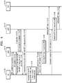
- FIG. 3 is a diagram for describing a MDT operation according to an embodiment.
- a UE 1c-05 may transit to a connected mode through a radio resource control (RRC) establishment procedure with a LTE base station (eNB) 1c-10, in operation 1c-25. Thereafter, the UE 1c-05 may be additionally connected to a NR base station (gNB) 1c-15 to perform data communication, as necessary.
- the NR base station 1c-15 may be connected to the LTE base station 1c-10 to transmit and receive required configuration information and general data to provide the UE 1c-05 with a service.
- the LTE base station 1c-10 may be connected to a MME which is a core network, whereas the NR base station 1c-15 may need not to be connected to an AMF.
- the structure is called EN-DC.
- the UE 1c-05 may report UE capability information to one of the LTE base station 1c-10 and the NR base station 1c-15, in operation 1c-30.
- FIG. 3 a procedure in which the UE 1c-05 reports UE capability information to the LTE base station 1c-10 is shown as an example, however, the UE 1c-05 may report UE capability information to the NR base station 1c-15.
- the UE capability information may indicate whether to support a MDT operation.
- the UE capability information may indicate whether to support a MDT operation in a MR-DC structure such as EN-DU.
- the LTE base station 1c-10 which has received the UE capability information may forward the UE capability information to another base station (in FIG. 3 , the NR base station 1c-15) existing in the EN-DC structure, in operation 1c-35.
- both the LTE base station1c-10 and the NR base station 1c-15 may set a connected mode MDT operation (immediate MDT) for the UE 1c-05. Also, the LTE base station 1c-10 and the NR base station 1c-15 may report MDT configuration information to each other and coordinate the MDT configuration information, in operation 1c-40. The coordination may be performed as follows.
- the LTE base station 1c-10 may report MDT configuration information triggered by itself to the NR base station 1c-15, and the NR base station 1c-15 may oppose, reject, or request change of the MDT configuration information.
- the NR base station 1c-15 may report MDT configuration information triggered by itself to the LTE base station 1c-10, and the LTE base station 1c-10 may oppose, reject, or request change of the MDT configuration information.
- the LTE base station 1c-10 may not report MDT configuration information triggered by itself to the NR base station 1c-15.
- the NR base station 1c-15 may report MDT configuration information triggered by itself to the LTE base station 1c-10, and the LTE base station 1c-10 may oppose, reject, or request change of the MDT configuration information.
- the LTE base station 1c-10 and NR base station 1c-15 may need not to report MDT configuration information triggered by themselves to the other base station, and may set a MDT operation independently.
- Option 4 although the LTE base station 1c-10 and NR base station 1c-15 report MDT configuration information triggered by themselves to the other base station, the LTE base station 1c-10 and NR base station 1c-15 may set a MDT operation independently. That is, the other base station may not oppose, reject, or request change of the MDT configuration information.
- Option 1 or Option 2 may need to be applied.
- the LTE base station 1c-10 or the NR base station 1c-15 may set a MDT operation for the UE 1c-05.
- the LTE base station 1c-10 may provide MDT configuration information to the UE 1c-05 through a predefined RRC message, in operation 1c-45.
- the predefined RRC message may belong to SRB1.
- the NR base station 1c-15 may provide MDT configuration information to the UE 1c-05 through a predefined RRC message belonging to SRB3, in operation 1c-50.
- the UE 1c-05 may perform a MDT operation according to the MDT configuration information.
- the LTE base station 1c-10 and NR base station 1c-15 may simultaneously provide independent MDT configuration information, respectively, to the UE 1c-05.
- the UE 1c-05 may perform two kinds of MDT operations simultaneously according to the MDT configuration information, in operation 1c-55.
- the UE 1c-05 may collect a frequency indicated by each piece of configuration information, and signal intensities and qualities measured from cells, and configure information that is to be reported to the LTE base station 1c-10 and the NR base station 1c-15.
- the UE 1c-05 may report a measurement result to the LTE base station 1c-10, in operation 1c-60.
- the LTE base station 1c-10 may collect measurement information related to the UE 1c-05, in operation 1c-65.
- the UE 1c-05 may report the measurement result to the NR base station 1c-15, in operation 1c-70.
- the NR base station 1c-15 may collect measurement information related to the UE 1c-05, in operation 1c-75, and forward the collected measurement information to the LTE base station 1c-10, in operation 1c-80.
- the LTE base station 1c-10 may transmit, in addition to information collected by itself, the information forwarded from the NR base station 1c-15 to a trace collection entity (TCE) server 1c-20, in operation 1c-85.
- TCE trace collection entity
- MDT measurement information may include information collected by and reported from UEs and information obtained by base stations.
- a scheduled IP throughput, a data volume, a DL packet delay, etc. may belong to information obtained by base stations.
- the information may be obtained as a result of involvement of various layers, such as PDCP, RLC, MAC, etc.
- a PDCP layer, a radio link control (RLC) layer, and a medium access control (MAC) layer may exist in different base stations. Accordingly, to obtain MDC measurement information, two base stations need to share information that they need.
- FIG. 4 is a diagram for describing a MDT operation according to another embodiment.
- a UE 1d-05 may transit to a connected mode through an RRC establishment procedure with a LTE base station 1d-10, in operation 1d-25. Thereafter, the UE 1d-05 may be additionally connected to a NR base station 1d-15 to perform data communication, as necessary.
- the NR base station 1d-15 may be connected to the LTE base station 1d-10 to transmit and receive required configuration information and general data to provide the UE 1d-05 with a service.
- the LTE base station 1d-10 may be connected to a MME which is a core network, whereas the NR base station 1d-15 may need not to be connected to an AMF.
- the structure is called EN-DC.
- the UE 1d-05 may report UE capability information to one of the LTE base station 1d-10 and the NR base station 1d-15, in operation 1d-30.
- a procedure in which the UE 1d-05 reports UE capability information to the LTE base station 1d-10 is shown as an example, however, the UE 1d-05 may report UE capability information to the NR base station 1d-15.
- the UE capability information may indicate whether to support a MDT operation.
- the UE capability information may indicate whether to support a MDT operation in a MR-DC structure such as EN-DU.
- the LTE station 1d-10 which has received the UE capability information may forward the UE capability information to another base station (in FIG. 4 , the NR base station 1d-15) existing in the EN-DC structure, in operation 1d-35.
- both the LTE base station 1d-10 and the NR base station 1d-15 may set a connected mode MDT operation (immediate MDT) for the UE 1d-05. Also, the LTE base station 1d-10 and the NR base station 1d-15 may report MDT configuration information to each other and coordinate the MDT configuration information, in operation 1d-40. The coordination may be performed as follows.
- the LTE base station 1d-10 may report MDT configuration information triggered by itself to the NR base station 1d-15, and the NR base station 1d-15 may oppose, reject, or request change of the MDT configuration information.
- the NR base station 1d-15 may report MDT configuration information triggered by itself to the LTE base station 1d-10, and the LTE base station 1d-10 may oppose, reject, or request change of the MDT configuration information.
- the LTE base station 1d-10 may not report MDT configuration information triggered by itself to the NR base station 1d-15.
- the NR base station 1d-15 may report MDT configuration information triggered by itself to the LTE base station 1d-10, and the LTE base station 1d-10 may oppose, reject, or request change of the MDT configuration information.
- the LTE base station 1d-10 and NR base station 1d-15 may need not to report MDT configuration information triggered by themselves to the other base station, and may set a MDT operation independently.
- Option 4 although the LTE base station 1d-10 and NR base station 1d-15 report MDT configuration information triggered by themselves to the other base station, the LTE base station 1d-10 and NR base station 1d-15 may set a MDT operation independently. That is, the other base station may not oppose, reject, or request change of the MDT configuration information.
- Option 1 or Option 2 may need to be applied.
- the LTE base station 1d-10 or the NR base station 1d-15 may set a MDT operation for the UE 1d-05.
- the LTE base station 1d-10 may provide MDT configuration information to the UE 1d-05 through a predefined RRC message, in operation 1d-45.
- the predefined RRC message may belong to SRB1.
- the NR base station 1d-15 may provide MDT configuration information to the UE 1d-05 through a predefined RRC message belonging to SRB3, in operation 1d-50.
- the UE 1d-05 may perform a MDT operation according to the MDT configuration information.
- the LTE base station 1d-10 and NR base station 1d-15 may simultaneously provide independent MDT configuration information, respectively, to the UE 1d-05.
- the UE 1d-05 may perform two kinds of MDT operations simultaneously according to the MDT configuration information, in operation 1d-55.
- the UE 1d-05 may collect a frequency indicated by each piece of configuration information, and signal intensities and qualities measured from cells, and configure information that is to be reported to the LTE base station 1d-10 and the NR base station 1d-15.
- the UE 1d-05 may report a measurement result to the LTE base station 1d-10, in operation 1d-60.
- the LTE base station 1d-10 may collect measurement information related to the UE 1d-05, in operation 1c-65, and transmit the measurement information to a TCE server 1d-20, in operation 1d-70.
- the UE 1d-05 may report the measurement result to the NR base station 1d-15, in operation 1d-75.
- the NR base station 1d-15 may collect measurement information related to the UE 1d-05, in operation 1d-80, and transmit the measurement information to the TCE server 1d-20, in operation 1d-85.
- FIG. 5 is a flowchart illustrating operations of a UE according to an embodiment.
- the UE may report UE capability information indicating that the UE can perform a MDT operation (in an EN-DC structure) to a LTE base station.
- the UE may receive MDT configuration information from the LTE base station.
- the UE may collect MDT measurement information according to the MDT configuration information, and report the MDT measurement information to the LTE base station.
- the UE may receive MDT configuration information from a NR base station.
- the UE may collect MDT measurement information according to the MDT configuration information, and report the MDT measurement information to the NR base station.
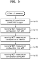
- FIG. 6 is a flowchart illustrating operations of a LTE base station (eNB) according to an embodiment.
- eNB LTE base station
- the LTE base station may receive, from a UE, a report about UE capability information indicating that the UE can support a MDT operation in EN-DC.
- the LTE base station may forward the UE capability information to a NR base station (gNB) which is the other base station of EN-DC.
- gNB NR base station
- the LTE base station may trigger a MDT operation for the UE, and coordinate MDT configuration information with the NR base station.
- the LTE base station may transmit the coordinated MDT configuration information to the UE.
- the LTE base station may receive a report about MDT measurement information from the UE.
- the LTE base station may receive a report about MDT measurement information collected by the NR base station.
- the LTE base station may report the MDT measurement information collected from the UE and the NR base station to a TCE server.
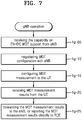
- FIG. 7 is a flowchart illustrating operations of a NR base station according to an embodiment.
- the NR base station may receive a report about UE capability information indicating that a specific UE can support a MDT operation in EN-DC from an LTE base station which is the other base station.
- the NR base station may trigger a MDT operation for the UE, and coordinate MDT configuration information with the LTE base station.
- the NR base station may transmit the coordinated MDT configuration information to the UE.
- the NR base station may receive a report about MDT measurement information from the UE.
- the NR base station may itself forward the MDT measurement information collected from the UE to a TCE server, or may forward the MDT measurement information to the LTE base station.
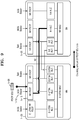
- FIG. 8 is a diagram for describing a procedure of obtaining a scheduled IP throughput in an EN-DC structure according to an embodiment.
- a DL scheduled IP throughput may be deduced by Equations below.
- Table 2 Definition Scheduled IP Throughput for MDT in DL. Throughput of PDCP SDU bits in downlink for data bursts that are large enough to require transmissions to be split across several TTIs, by excluding the data transmitted in the last TTI of the data burst. Only data transmission time is considered, i.e. when data transmission over Uu has begun but not yet finished. The measurement is performed per RAB per UE, and also per UE. For successful reception, the reference point is MAC upper SAP.
- a data burst begins at the point in time when the first transmission begins after a PDCP SDU becomes available for transmission, where previously no PDCP SDUs were available for transmission for the E-RAB (in per E-RAB per UE case) or for any E-RABs of the UE (in per UE case).
- the data burst ends at the point in time when transmissions are successfully completed and there is no portion of a PDCP SDU pending transmission for the E-RAB (in per E-RAB per UE case) or for any E-RABs of the UE (in per UE case).
- ThpTimeDl 0 [ kbits l s ]
- ThpTimeDl T 1 - T 2 [ms]. T 1 If transmission of a data burst is ongoing at the end of the measurement period, then T1 is the point in time when the measurement period ends.
- T1 is the point in time when the last TTI used for transmission of the data burst begins.
- T 2 If transmission of a data burst is ongoing at the start of the measurement period, then T2 is the point in time when the measurement period begins. Otherwise, T2 is the point in time when the first TTI used for transmission of the data burst begins.
- ThpVolDl The data volume, counted on PDCP SDU level, in kbits successfully transmitted (acknowledged by UE) in DL for the data burst excluding the data volume transmitted in the last TTI.
- a UL scheduled IP throughput may be deduced by Equations below.
- eNB estimate of the throughput of PDCP SDU bits in uplink for data bursts that are large enough to require transmissions to be split across several TTIs by excluding the data transmitted in the last TTI of the data burst. Only data transmission time is considered, i.e. when data transmission over Uu has begun but not yet finished. The measurement is performed per UE. For successful reception, the reference point is MAC upper SAP.
- a data burst begins at the point in time when the first transmission begins after the eNB estimate of the UE buffer size becomes greater than zero for at least one E-RAB of the UE, where previously the estimate was zero for all E-RABs of the UE.
- the data burst ends at the point in time when transmissions are successfully completed and the eNB estimate of the UE buffer size becomes zero for all E-RABs of the UE, where previously the estimate was greater than zero for at least one E-RAB of the UE.
- ThpTimeUl 0 [ kbits / s ]
- ThpTimeUl T 1 - T 2 [ms]. T 1 If transmission of a data burst is ongoing at the end of the measurement period, then T1 is the point in time when the measurement period ends.
- T1 is the point in time when the last TTI used for transmission of the data burst begins.
- T 2 If transmission of a data burst is ongoing at the start of the measurement period, then T2 is the point in time when the measurement period begins. Otherwise, T2 is the point in time when the first TTI used for transmission of the data burst begins.
- ThpVolUl The data volume counted on PDCP SDU level in kbits received in UL for the data burst excluding the data volume received in the last TTI used for transmission of the data burst.
- a data volume (per packet data convergence protocol service data unit (PDCP SDU)) may need to be measured in a PDCP layer, and an effective transmission time may need to be measured in a MAC layer. That is, because values of T1 and T2 are deduced for each transmission time interval (TTI), T1 and T2 may be times at which a MAC PDU is transferred to PHY in MAC lower SAP. Also, whether data transmission is successful may be determined in MAC upper SAP (between a MAC layer and a RLC layer). Then, a scheduled IP throughput may be calculated by using the deduced values.
- TTI transmission time interval
- a PDCP layer, a MAC layer, and a RLC layer for a specific radio bearer (RB) may belong to different base stations.
- a PDCP layer 1h-15 may exist in a LTE base station 1h-30 which is a master node (MN) and a RLC layer 1h-20 and a MAC layer 1h-25 may exist in a NR base station 1h-35 which is a secondary node (SN).
- MN master node
- a MAC layer 1h-25 may exist in a NR base station 1h-35 which is a secondary node (SN).
- a PDCP SDU 1h-05 which has arrived at an upper SAP of the PDCP layer 1h-15 of the LTE base station 1h-30 may be processed and transmitted to the RLC layer 1h-20 of the NR base station 1h-35. Accordingly, because a NR base station finally calculating a scheduled IP throughput needs to have all required information, NR base stations may need to share the information.
- a NR base station calculating a scheduled IP throughput may be a NR base station having a PDCP layer.
- information collected by the RLC and MAC layers of the other base station may be transmitted to the base station having the PDCP layer.
- the information to be transmitted may be values of T1 and T2 or ThpTimeDL and ThpTimeUL.
- the information may be transmitted through a predefined control message of an X2 interface.
- a base station calculating a scheduled IP throughput may be a base station that has provided MDT configuration information.
- Information collected by the PDCP, RLC, and MAC layers may be transmitted to the base station that has provided the MDT configuration information.
- the information to be transmitted may include all values required to deduce a scheduled IP throughput.
- the information may be transmitted through a predefined control massage of an X2 interface.
- FIG. 9 is a diagram for describing a procedure of obtaining and deducing a data volume in an EN-DC structure according to an embodiment.
- Uplink and downlink data volumes may be defined as follows.
- a PDCP SDU 1i-05 is criterion for measuring a data volume. Accordingly, only a PDCP layer 1i-15 may be involved in the corresponding measurement information.
- a base station calculating a data volume may be a base station having a PDCP layer.
- a LTE base station 1i-20 may be a base station having the PDCP layer 1i-15.
- data volume information may be reported to the base station that has provided the MDT configuration information.
- the LTE base station 1i-20 may transmit collected data volume information to the NR base station 1i-25.
- the data volume information may be transmitted through a predefined control message of an X2 interface.
- FIG. 10 is a diagram for describing a procedure for obtaining a DL packet delay in an EN-DC structure according to an embodiment.
- a downlink packet delay may be deduced by Equations below.
- tArriv ( i ) The point in time when PDCP SDU i arrives.
- tAck ( i ) The point in time when the last piece of PDCP SDU i was received by the UE according to received HARQ feedback information.
- i A PDCP SDU that arrives at the PDCP upper SAP during time period T .
- PDCP SDU for which HARQ acknowledgement is not received for all parts shall not be included in the calculation.
- a PDCP layer may need to measure values of tArrive and I(T), and a MAC layer may need to measure a time tAck at which HARP feedback of each PDCP SDU is received. Then, through the obtained values, a packet delay may be calculated.
- a PDCP layer and a MAC layer for a specific RB may belong to different base stations.
- a PDCP layer 1j-15 may exist in a LTE base station 1j-30 which is a MN, and a RLC layer 1j-20 and a MAC layer 1j-25 may exist in a NR base station 1j-35 which is a SN.
- a PDCP SDU 1j-05 which has arrived at a upper SAP of the PDCP layer 1j-15 of the LTE base station 1j-30 may be processed and transmitted to the RLC layer 1j-20 of the NR base station 1j-35. Accordingly, because a base station finally calculating a packet delay needs to have all required information, base stations may need to share the information.
- a base station calculating a packet delay may be a base station having a PDCP layer.
- a MAC layer for a specific RB does not belong to a base station having a PDCP layer and belongs to another base station
- information collected by the MAC layer of the other base station may be transmitted to the base station having the PDCP layer.
- the information to be transmitted may include a value of rAck.
- the information may be transmitted through a predefined control message of an X2 interface.
- a base station calculating a packet delay may be a base station that has provided MDT configuration information.
- Information collected by the PDCP and MAC layers may be transmitted to the base station that has provided the MDT configuration information.
- the information to be transmitted may include all values required to deduce a packet delay.
- the information may be transmitted through a predefined control massage of the X2 interface.
- FIG. 11 is a diagram for describing a procedure of obtaining a scheduled IP throughput in a CU-DU structure according to an embodiment.
- the CU-DU structure is a base station structure in which a node (CU) 1k-05 having a PDCP layer 1k-15 or the upper layer is spatially or physically separated from a node (DU) 1k-10 having a RLC layer 1k-20, a MAC layer 1k-25, and a PHY layer 1k-30.
- a CU having a PDCP layer may receive information required for calculating measurement information from a DU to obtain the measurement information.
- the CU may function to transmit the measurement information to a TCE server.
- a node calculating a scheduled IP throughput may be a CU having a PDCP layer.
- Information collected by RLC and MAC layers of a DU may be transmitted to the CU having the PDCP layer.
- the information to be transmitted may include values of T1 and T1 or ThpTimeDL and ThpTimeUL.
- the information may be transmitted through a predefined control message of an X2 interface or a F1-AP interface.
- FIG. 12 is a diagram for describing a procedure of obtaining a data volume in a CU-DU structure according to an embodiment.
- a data volume may be defined as an amount of bits of PDCP SDU 1l-15 that is transmitted/received between a PDCP layer and a RLC layer.
- a PDCP layer of a CU 1l-05 may count an amount of bits that are transmitted to a DU 1l-10 to obtain a data volume.
- FIG. 13 is a diagram for describing a procedure for obtaining a DL packet delay in a CU-DU structure according to an embodiment.
- a node calculating a packet delay may be a CU 1m-05 having a PDCP layer 1m-15.
- Information collected by a MAC layer 1m-20 of a DU 1m-10 may be transmitted to the CU 1m-05 having the PDCP layer 1m-15.
- the information to be transmitted may include a value of rAck.
- the information may be transmitted through a predefined control message of an X2 interface or a F1-AP interface.
- the PDCP layer 1m-15 of the CU 1m-05 may obtain a value of tArriv.
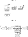
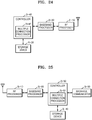
- FIG. 14 is a block diagram illustrating a structure of a UE according to an embodiment.
- the UE may include a radio frequency (RF) processor 1n-10, a baseband processor 1n-20, a storage device 1n-30, and a controller 1n-40.
- RF radio frequency
- the RF processor 1n-10 may perform a function of transmitting/receiving signals through band conversion, amplification, etc. of the signals through a wireless channel. That is, the RF processor 1n-10 may up-convert a baseband signal provided from the baseband processor 1n-20 into an RF band signal, transmit the RF band signal through an antenna, and down-convert an RF band signal received through the antenna into a baseband signal.
- the RF processor 1n-10 may include a transmitter filter, a receiver filter, an amplifier, a mixer, an oscillator, a digital to analog convertor (DAC), an analog to digital convertor (ADC), etc.
- DAC digital to analog convertor
- ADC analog to digital convertor
- FIG. 20 a single antenna is shown, however, the UE may include a plurality of antennas.
- the RF processor 1n-10 may include a plurality of RF chains. Furthermore, the RF processor 1n-10 may perform beamforming. For beamforming, the RF processor 1n-10 may adjust phases and magnitudes of signals that are transmitted/received through a plurality of antennas or antenna elements. Also, the RF processor 1n-10 may perform multiple input multiple output (MIMO), and receive several layers when performing a MIMO operation.
- MIMO multiple input multiple output
- the baseband processor 1n-20 may perform a function of conversion between a baseband signal and a bit string according to a physical layer specification of a system. For example, upon data transmission, the baseband processor 1n-20 may encode and modulate a transmission bit string to generate complex symbols. Also, upon data reception, the baseband processor 1n-20 may demodulate and decode a baseband signal provided from the RF processor 1n-10 to restore a reception bit string. For example, according to an OFDM method, upon data transmission, the baseband processor 1n-20 may encode and modulate a transmission bit string to generate complex symbols, map the complex symbols to subcarriers, and then configure OFDM symbols through an inverse fast Fourier transform (IFFT) operation and cyclic prefix (CP) insertion.
- IFFT inverse fast Fourier transform
- CP cyclic prefix
- the baseband processor 1n-20 may segment a baseband signal provided from the RF processor 1n-10 in unit of OFDM symbols, restore signals mapped to subcarriers through a fast Fourier transform (FFT) operation, and then restore a reception bit string through demodulation and decoding.
- FFT fast Fourier transform
- the baseband processor 1n-20 and the RF processor 1n-10 may transmit and receive signals as described above. Accordingly, the baseband processor 1n-20 and the RF processor 1n-10 may be referred to as a transmitter, a receiver, a transceiver, or a communicator. Furthermore, at least one of the baseband processor 1n-20 and the RF processor 1n-10 may include a plurality of communication modules to support a plurality of different radio access technologies. Also, at least one of the baseband processor 1n-20 and the RF processor 1n-10 may include different communication modules to process signals of different frequency bands. For example, the different radio access technologies may include a wireless local area network (WLAN) (for example, IEEE 802.11), a cellular network (for example, LTE), etc. Also, the different frequency bands may include a super high frequency (SHF) (for example, 2.NRHz, NRhz) band and a millimeter (mm) wave (for example, 60 GHz) band.
- WLAN wireless local area network
- a cellular network
- the storage device 1n-30 may store data, such as a basic program, an application program, configuration information, etc., for operations of the UE. Also, the storage device 1n-30 may provide the stored data according to a request from the controller 1n-40.
- the controller 1n-40 may control overall operations of the UE.
- the controller 1n-40 may transmit and receive signals through the baseband processor 1n-20 and the RF processor 1n-10.
- the controller 1n-40 may record data in the storage device 1n-30 and read data from the storage device 1n-30.
- the controller 1n-40 may include at least one processor.
- the controller 1n-40 may include a communication processor (CP) that performs a control for communication and an application processor (AP) that controls an upper layer such as an application program.
- CP communication processor
- AP application processor
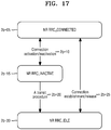
- FIG. 15 is a block diagram illustrating a structure of a base station according to an embodiment.
- the base station may include a RF processor 1o-10, a baseband processor 1o-20, a backhaul communicator 1o-30, a storage device 1o-40, and a controller 1o-50.
- the RF processor 1o-10 may perform a function for transmitting and receiving signals through a wireless channel, such as band conversion, amplification, etc. of signals. That is, the RF processor 1o-10 may up-convert a baseband signal provided from the baseband processor 1o-20 into a RF band signal, transmit the RF band signal through an antenna, and down-convert an RF band signal received through the antenna into a baseband signal.
- the RF processor 1o-10 may include a transmission filter, a reception filter, an amplifier, a mixer, an oscillator, a DAC, an ADC, etc.
- FIG. 15 a single antenna is shown, however, the base station may include a plurality of antennas.
- the RF processor 1o-10 may include a plurality of RF chains. Furthermore, the RF processor 1o-10 may perform beamforming. For beamforming, the RF processor 1o-10 may adjust phases and magnitudes of signals that are transmitted/received through the plurality of antennas or antenna elements. The RF processor 1o-10 may perform a downlink MIMO operation by transmitting one or more layers.
- the baseband processor 1o-20 may perform a function of conversion between baseband signals and bit strings according to a physical layer specification. For example, upon data transmission, the baseband processor 1o-20 may encode and modulate a transmission bit string to generate complex symbols. Also, upon data reception, the baseband processor 1o-20 may demodulate and decode a baseband signal provided from the RF processor 1o-10 to restore a reception bit string. For example, according to the OFDM method, upon data transmission, the baseband processor 1o-20 may encode and modulate a transmission bit string to generate complex symbols, map the complex symbols to subcarriers, and then construct OFDM symbols through IFFT and CP insertion.
- the baseband processor 1o-20 may segment a baseband signal provided from the RF processor 1o-10 in units of OFDM symbols, restore signals mapped to subcarriers through FFT, and then restore a reception bit string through demodulation and decoding.
- the baseband processor 1o-20 and the RF processor 1o-10 may transmit and receive signals as described above. Accordingly, the baseband processor 1o-20 and the RF processor 1o-10 may be also referred to as a transmitter, a receiver, a transceiver, a communicator, or a wireless communicator.
- the backhaul communicator 1o-30 may provide an interface for communicating with other nodes in a network. That is, the backhaul communicator 1o-30 may convert a bit string that is transmitted from a master base station to another node (for example, a secondary base station, a core network, etc.) into a physical signal, and convert a physical signal received from another node into a bit string.
- a master base station for example, a secondary base station, a core network, etc.
- the storage device 1o-40 may store data, such as basic programs, application programs, and configuration information, for operations of the master base station. Particularly, the storage device 1o-40 may store information about a bearer assigned to a UE connected to the base station, a measurement result reported from the connected UE, etc. Also, the storage device 1o-40 may store information that is used as determination criterion about whether to provide multiple connections to the UE or whether to release multiple connections to the UE. Also, the storage device 1o-40 may provide the stored data according to a request from the controller 1o-50.
- the controller 1o-50 may control overall operations of the master base station. For example, the controller 1o-50 may transmit and receive signals through the baseband processor 1o-20 and the RF processor 1o-10 or through the backhaul communicator 1o-30. Also, the controller 1o-50 may write data in the storage device 1o-40 or read data from the storage device 1o-40. To write or read data, the controller 1o-50 may include at least one processor.
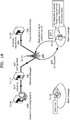
- FIG. 16 illustrates a structure of a next-generation mobile communication system to which an embodiment is applied.
- a radio access network of a next-generation mobile communication system may be configured with a next-generation base station (NR NB, NR gNB, or gNB) 2a-10 and an AMF 2a-05 or a NR CN (or NG CN).
- NR NB, NR gNB, or gNB next-generation base station
- AMF 2a-05 or a NR CN (or NG CN) may be connected to an external network through the NR gNB 2a-10 and the AMF 2a-05.
- the NR gNB 2a-10 may correspond to an eNB of a LTE system.
- the NR gNB 2a-10 may be connected to the NR UE 2a-15 through a wireless channel, and provide a superior service than a legacy node B.
- a device for performing scheduling by collecting status information of UEs, such as buffer statuses of UEs, available transmission power states of UEs, channel states of UEs, etc. is needed.
- the NR gNB 2a-10 may function as such a device.
- An NR gNB 2a-10 may generally control a plurality of cells, and may be configured with a CU for managing control and signaling and a DU being in charge of transmission/reception of signals.
- the next-generation mobile communication system may use a legacy maximum bandwidth or more, and combine OFDM as air interface technology with beam-forming technology.
- the next-generation mobile communication system may apply AMC of determining a modulation scheme and a channel coding rate according to a channel state of a UE.
- the AMF 2a-05 may perform functions, such as mobility support, bearer setup, QoS setup, etc.
- the AMF 2a-05 may be in charge of various control functions, as well as a mobility management function for UEs, and may be connected to a plurality of base stations. Also, the next-generation mobile communication system (5G or NR system) may interwork with legacy LTE systems, and the AMF 2a-05 may be connected to a MME 2a-25 through a network interface.
- the MME 2a-25 may be connected to an eNB 2a-30 which is a legacy base station.
- a UE supporting EN-DC may be connected to the eNB 2a-30, as well as the gNB 2a-10, to transmit and receive data (2a-35).
- the EN-DC only LTE systems may be connected to a core network (MME 2a-25), and the LTE systems may be connected to a NR base station.
- FIG. 17 is a diagram for describing transition of an RRC state in a next-generation mobile communication system to which an embodiment is applied.
- Next-generation mobile communication system supports three RRC states.
- a connected mode (RRC_CONNECTED) 2b-05 may refer to an RRC state in which the UE can transmit and receive data.
- An idle mode (RRC_IDLE) 2b-30 may refer to an RRC state in which the UE monitors whether paging is transmitted to itself.
- the two modes may be RRC states that are also applied to legacy LTE systems, and may be the same as those of the legacy LTE systems.
- an RRC inactive state (RRC_INACTIVE) 2b-15 may be newly defined.
- RRC_INACTIVE In the RRC inactive state (RRC_INACTIVE) 2b-15), UE context may be maintained in a base station and a UE, and RAN-based paging may be supported.
- RRC_INACTIVE Features of the new RRC inactive state (RRC_INACTIVE) 2b-15 are listed as follows.
- the new RRC inactive state (RRC_INACTIVE) 2b-15 may transit to the connected mode (RRC_CONNECTED) 2b-05 or the idle mode (RRC_IDLE) 2b-30 by using a specific procedure.
- the RRC inactive state (RRC_INACTIVE) 2b-15 (also, referred to as an inactive mode) may transit to the connected mode (RRC_CONNECTED) 2b-05 according to a connection activation procedure, and the connected mode (RRC_CONNECTED) 2b-05 may transit to the inactive mode (RRC_INACTIVE) 2b-15 according to a connection inactivation procedure, in operation 2b-10.
- the connection activation/inactivation procedure may be performed by transmitting/receiving at least one RRC message between the UE and the base station, and may be configured with at least one operation.
- the inactive mode (RRC_INACTIVE) 2b-15 may transit to the idle mode (RRC_IDLE) 2b-30 (2b-20) according to a specific procedure, in operation 2b-20.
- the specific procedure may be one of various methods, such as exchanging specific messages or a timer-based or event-based method. Transition between the connected mode (RRC_CONNECTED) 2b-05 and the idle mode (RRC_IDLE) 2b-30 may be based on legacy LTE technology. That is, mode transition may be performed through a connection establishment/release procedure, in operation 2b-25.
- FIG. 18 is a diagram for describing technology of collecting and reporting cell measurement information according to another embodiment.
- a mobile network operator Upon network establishment or network optimization, a mobile network operator performs a procedure of measuring signal intensity in a general expected service area and arranging or rearranging base stations in the service area based on the measured signal intensity. In the procedure, the mobile network operator loads signal measurement equipment in a vehicle and moves to collect cell measurement information in the service area. The procedure is called a drive test. The drive test requires a long time and a lot of expense.
- UEs may have a function for measuring signals received from a base station. Accordingly, instead of the drive test, UEs existing in a service area may be used. The procedure is called a minimization of drive test (MDT).
- MDT minimization of drive test
- the mobile network operator may set a MDT operation for specific UEs through several components of a network, and the UEs for which the MDT operation has been set and is in a connected mode RRC_Connected, an idle mode RRC_Idle, or an inactive mode RRC_Inactive may collect and store signal intensity information from a serving cell and neighboring cells.
- the UEs for which the MDT operation has been set may store various information, such as position information, time information, and signal quality information, together with the signal intensity information.
- the stored information may be reported to the network when the corresponding UEs are in the connected mode RRC_Connected, and, in this case, the stored information may be transferred to a specific server.
- Information collected by a UE may be reported to a base station through a MDT operation, and the MDT operation may be classified into immediate MDT and logged MDT.
- the immediate MDT may be an operation of immediately reporting collected information to a network. Because the immediate MDT is to immediately report collected information, a UE being in a connected mode may perform the immediate MDT. Generally, the immediate MDT may reuse a RRM procedure for supporting operations, such as handover, addition of a serving cell, etc., and position information, time information, etc. may be additionally reported.
- the logged MDT may be an operation of storing collected information, instead of immediately reporting the collected information to a network, and reporting, after a UE transits to a connected mode, the stored information to the network.
- a UE being in an idle mode in which stored information cannot be immediately reported to a network may perform the logged MDT.
- a UE belonging to a next-generation mobile communication system and being in an inactive mode may perform the logged MDT.
- a network may provide the UE with configuration information for performing a logged MDT operation, and the UE which has received the configuration information may collect and store the configuration information after the UE transits to an idle mode or an inactive mode.
- FIG. 19 is a diagram for describing a procedure of collecting and reporting cell measurement information in a LTE system according to an embodiment.
- a UE 2d-05 may transit to a connected mode through an RRC establishment procedure with a LTE base station (eNB) 2d-10, in operation 2d-15.
- the LTE base station 2d-10 may set a logged MDT operation for the UE 2d-05 through a loggedMeasurementConfiguration message, in operation 2d-20.
- the UE 2d-05 may start a T330 timer.
- the LTE base station 2d-10 may transit the connected mode of the UE 2d-05 to an idle mode by using an RRCConnectionRelease message, in operation 2d-25.
- the UE 2d-05 may perform the logged MDT operation by using received configuration information. That is, the UE 2d-05 may collect and record predefined measurement information periodically, in operation 2d-30. The operation may be performed in the idle mode when the T330 timer is running. The T330 timer may be continuously running regardless of an RRC state. The UE 2d-05 may stop the corresponding operation when again transiting to the connected mode, although the T330 timer is still running. When the T330 timer is expired, the logged MDT operation may terminate.
- a condition for performing the logged MDT operation may be additionally considered.
- an amount of measurement information that can be recorded through a logged MDT operation may be limited by a UE memory size. Because a purpose of MDT is optimization of a service area, it may be efficient to perform a MDT operation while focusing on regions where signal quality or service quality is poor. Because measurement information of only regions with problems is reported to a network, signaling overhead which is caused by unnecessary information transmission may be minimized.
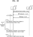
- FIG. 20 is a diagram for describing a procedure of performing event-based logging according to an embodiment.
- a UE 2e-05 may transit from an idle mode or an inactive mode to a connected mode through an RRC establishment procedure or an RRC resume procedure with a NR base station (gNB) 2e-10, in operation 2e-15.
- the base station 2e-10 may set a logged MDT operation for the UE 2e-05 by using a predefined RRC message, in operation 2e-20.
- Configuration information of logged MDT may be applied to the idle mode, to the inactive mode, or to both the idle mode and the inactive mode.
- the base station 2e-10 may indicate an RRC state of performing logged MDT with MDT configuration information.
- the MDT configuration information may include at least one condition for performing a logged MDT operation.
- the UE 2e-05 may start a first timer.
- the base station 2e-10 may transit a connected mode of the UE 2e-05 to the idle mode or the inactive mode by using an RRCRelease message, in operation 2e-25.
- the MDT configuration information may be included in the RRCRelease message.
- the UE 2e-05 when the UE 2e-05 being in the idle mode or the inactive mode meets a preset condition, the UE 2e-05 may perform logged MDT.
- the UE 2e-05 When the UE 2e-05 is in the idle mode (or the inactive mode), the first timer is running, and the preset condition meets, the UE 2e-05 may perform a logged MDT operation, in operation 2e-30.
- the UE 2e-05 When the preset condition meets, the UE 2e-05 may perform the logged MDT operation periodically, and store collected measurement information, in operation 2e-35.
- the UE 2e-05 may stop the logged MDT operation, in operation 2e-40.
- the preset condition may be applied to both an entering condition and a leaving condition.
- a condition for starting a logged MDT operation and a condition for stopping a logged MDT operation may be provided separately. Also, a plurality of conditions may be set.
- the logged MDT operation may also terminate, in operation 2e-45. Recorded MDT measurement information may be deleted from a memory of the UE 2e-05 when a predefined time elapses after the first timer is expired.
- FIG. 21 is a diagram for describing a procedure of performing event-triggered periodic logging according to an embodiment.
- a UE 2f-05 may transit from an idle mode or an inactive mode to a connected mode through an RRC establishment procedure or an RRC resume procedure with a NR base station (gNB) 2f-10, in operation 2f-15.
- the base station 2f-10 may set a logged MDT operation for the UE 2f-05 by using a predefined RRC message, in operation 2f-20.
- Configuration information of logged MDT may be applied to the idle mode, to the inactive mode, or to both the idle mode and the inactive mode.
- the base station 2f-10 may indicate an RRC state for performing logged MDT with MDT configuration information.
- the MDT configuration information may include at least one condition for performing a logged MDT operation.
- the UE 2f-05 may start a first timer.
- the base station 2f-10 may transit the connected mode of the UE 2f-05 to the idle mode or the inactive mode by using an RRCRelease message, in operation 2f-25.
- the MDT configuration information may be included in the RRCRelease message.
- the UE 2f-05 when the UE 2f-05 being in the idle mode or the inactive mode meets a preset condition, the UE 2f-05 may start logged MDT.
- the UE 2f-05 When the UE 2f-05 is in the idle mode (or the inactive mode), the first timer is running, and the preset condition meets, the UE 2f-05 may start a logged MDT operation, in operation 2f-30.
- the preset condition may be an entering condition, and the logged MDT operation may be performed until the first timer is expired. That is, measurement information may be collected and stored periodically, in operation 2f-35.
- the logged MDT When transition to the connection mode again occurs although the first timer is running, the logged MDT may stop.
- a plurality of entering conditions may be set.
- the logged MDT operation may also terminate, in operation 2f-40.
- Recorded MDT measurement information may be deleted from a memory of the UE 2f-05 when a predefined time elapses after the first timer is expired.
- FIG. 22 is a diagram for describing a procedure of performing one-shot logging according to an embodiment.
- a UE 2g-05 may transit from an idle mode or an inactive mode to a connection mode through an RRC establishment procedure or an RRC resume procedure with a NR base station (gNB) 2g-10, in operation 2g-15.
- the base station 2g-10 may set a logged MDT operation for the UE 2g-05 by using a predefined RRC message, in operation 2g-20.
- Configuration information of logged MDT may be applied to the idle mode, to the inactive mode, or to both the idle mode and the inactive mode.
- the base station 2g-10 may indicate an RRC state for performing logged MDT with MDT configuration information.
- the MDT configuration information may include at least one condition for performing a logged MDT operation.
- the UE 2g-05 may start a first timer.
- the base station 2g-10 may transit the connection mode of the UE 2g-05 to the idle mode or the inactive mode by using an RRCRelease message, in operation 2g-25.
- the MDT configuration information may be included in the RRCRelease message.
- the UE 2g-05 when the UE 2g-05 being in the idle mode or the inactive mode meets a preset condition, the UE 2g-05 may perform a logged MDT operation one time.
- the UE 2g-05 When the UE 2g-05 is in the idle mode (or inactive mode), the first timer is running, and the preset condition meets, the UE 2g-05 may perform the logged MDT operation one time, in operation 2g-30.
- Performing the logged MDT operation one time may mean collecting and storing a set of latest effective MDC measurement information.
- transition to the connection mode again occurs although the first timer is running the logged MDT operation may stop.
- a plurality of entering conditions may be set.
- the logged MDT operation may also terminate, in operation 2g-35.
- Recorded MDT measurement information may be deleted from a memory of the UE 2g-05 when a predefined time elapses after the first timer is expired.
- FIG. 23 is a diagram for describing a procedure of collecting and reporting cell measurement information based on a plurality of pieces of MDT configuration information according to an embodiment.
- a UE 2h-05 may transit from an idle mode or an inactive mode to a connection mode through an RRC establishment procedure or an RRC Resume procedure with a NR base station (gNB) 2h-10, in operation 2h-15.
- the base station 2h-10 may set a logged MDT operation for the UE 2h-05 by using a predefined RRC message, in operation 2h-20.
- Configuration information of logged MDT may be applied to the idle mode, to the inactive mode, or to both the idle mode and the inactive mode.
- the base station 2h-10 may indicate an RRC state of performing logged MDT with MDT configuration information.
- the MDT configuration information may include at least one condition for performing a logged MDT operation.
- the UE 2h-05 may start a first timer.
- the base station 2h-10 may transit the connection mode of the UE 2h-05 to the idle mode or the inactive mode by using an RRCRelease message, in operation 2h-25.
- the MDT configuration information may be included in the RRCRelease message.
- the base station 2h-10 may provide a plurality of pieces of configuration information required for performing a logged MDT operation.
- the UE 2h-05 may apply configuration information corresponding to the condition to perform a logged MDT operation.
- a set of pieces of configuration information for the logged MDT operation may be configured with the following information.
- another loggingInterval value may be applied to perform a logged MDT operation.
- the UE 2h-05 may perform a logged MDT operation by using configuration information (first configuration information) considered as a default among a plurality of pieces of configuration information, in operation 2h-25. While a specific preset condition is satisfied in operation 2h-35 while the UE 2h-05 is performing the logged MDT operation by using the first configuration information in operation 2h-30, the UE 1h-05 may perform a logged MDT operation by using second configuration information, in operation 2h-40.
- configuration information first configuration information
- the specific preset condition when the specific preset condition is that signal intensity of a serving cell is lower than or equal to predefined intensity and the second configuration information indicates a shorter logging interval, this may mean recording MDT measurement information at shorter intervals in a region where signal quality is poor. Accordingly, more measurement information may be provided to improve a region where signal quality is poor.
- the condition does not meet in operation 2h-45, the UE 1h-05 may perform the logged MDT operation by again using the first configuration information, in operation 2h-50.
- the specific preset condition may be applied to both an entering condition and a leaving condition.
- a condition for starting a logged MDT operation and a condition for stopping a logged MDT operation may be provided separately.
- a plurality of conditions may be set.
- the logged MDT operation When the first timer is expired, the logged MDT operation may also terminate (2h-55). Recorded MDT measurement information may be deleted from a memory of the UE 1h-05 when a predefined time elapses
- the conditions mentioned in the above-described embodiments may include the following conditions.
- the following information may be additionally recorded.
- FIG. 24 is a block diagram illustrating a structure of a UE according to an embodiment.
- the UE may include a radio frequency (RF) processor 2i-10, a baseband processor 2i-20, a storage device 2i-30, and a controller 2i-40.
- RF radio frequency
- the RF processor 2i-10 may perform a function for transmitting/receiving signals through a wireless channel, such as band conversion, amplification, etc. of the signals. That is, the RF processor 2i-10 may up-convert a baseband signal provided from the baseband processor 2i-20 into an RF band signal, transmit the RF band signal through an antenna, and down-convert an RF band signal received through the antenna into a baseband signal.
- the RF processor 2i-10 may include a transmitter filter, a receiver filter, an amplifier, a mixer, an oscillator, a digital to analog convertor (DAC), an analog to digital convertor (ADC), etc.
- DAC digital to analog convertor
- ADC analog to digital convertor
- the UE may include a plurality of antennas.
- the RF processor 2i-10 may include a plurality of RF chains.
- the RF processor 2i-10 may perform beamforming. For beamforming, the RF processor 2i-10 may adjust phases and magnitudes of signals that are transmitted/received through a plurality of antennas or antenna elements. Also, the RF processor 2i-10 may perform MIMO, and receive several layers when performing a MIMO operation.
- the baseband processor 2i-20 may perform a function of conversion between a baseband signal and a bit string according to a physical layer specification of a system. For example, upon data transmission, the baseband processor 2i-20 may encode and modulate a transmission bit string to generate complex symbols. Also, upon data reception, the baseband processor 2i-20 may demodulate and decode a baseband signal provided from the RF processor 2i-10 to restore a reception bit string. For example, according to an OFDM method, upon data transmission, the baseband processor 2i-20 may encode and modulate a transmission bit string to generate complex symbols, map the complex symbols to subcarriers, and then configure OFDM symbols through an IFFT operation and CP insertion.
- OFDM OFDM
- the baseband processor 2i-20 may segment a baseband signal provided from the RF processor 2i-10 in unit of OFDM symbols, restore signals mapped to subcarriers through a FFT operation, and then restore a reception bit string through demodulation and decoding.
- the baseband processor 2i-20 and the RF processor 2i-10 may transmit and receive signals as described above. Accordingly, the baseband processor 2i-20 and the RF processor 2i-10 may be referred to as a transmitter, a receiver, a transceiver, or a communicator. Furthermore, at least one of the baseband processor 2i-20 and the RF processor 2i-10 may include a plurality of communication modules to support a plurality of different radio access technologies. Also, at least one of the baseband processor 2i-20 and the RF processor 2i-10 may include different communication modules to process signals of different frequency bands. For example, the different radio access technologies may include a wireless local area network (WLAN) (for example, IEEE 802.11), a cellular network (for example, LTE), etc. Also, the different frequency bands may include a super high frequency (SHF) (for example, 2.NRHz, NRhz) band and a millimeter (mm) wave (for example, 60 GHz) band.
- WLAN wireless local area network
- cellular network for example
- the storage device 2i-30 may store data, such as a basic program, an application program, setting information, etc., for operations of the UE. Also, the storage device 2i-30 may provide the stored data according to a request from the controller 2i-40.
- the controller 2i-40 may control overall operations of the UE. For example, the controller 2i-40 may transmit and receive signals through the baseband processor 2i-20 and the RF processor 2i-10. Also, the controller 2i-40 may record data in the storage device 2i-30 and read data from the storage device 2i-30. For this, the controller 2i-40 may include at least one processor. For example, the controller 2i-40 may include a communication processor (CP) that performs a control for communication and an application processor (AP) that controls an upper layer such as an application program.
- CP communication processor
- AP application processor
- FIG. 25 is a block diagram illustrating a structure of a base station according to an embodiment.
- the base station may include a RF processor 2j-10, a baseband processor 2j-20, a backhaul communicator 2j-30, a storage device 2j-40, and a controller 2j-50.
- the RF processor 2j-10 may perform a function for transmitting and receiving signals through a wireless channel, such as band conversion, amplification, etc. of signals. That is, the RF processor 2j-10 may up-convert a baseband signal provided from the baseband processor 2j-20 into a RF band signal, transmit the RF band signal through an antenna, and down-convert an RF band signal received through the antenna into a baseband signal.
- the RF processor 2j-10 may include a transmission filter, a reception filter, an amplifier, a mixer, an oscillator, a DAC, an ADC, etc.
- FIG. 25 a single antenna is shown, however, the base station may include a plurality of antennas.
- the RF processor 2j-10 may include a plurality of RF chains. Furthermore, the RF processor 2j-10 may perform beamforming. For beamforming, the RF processor 2j-10 may adjust phases and magnitudes of signals that are transmitted/received through the plurality of antennas or antenna elements. The RF processor 2j-10 may perform a downlink MIMO operation by transmitting one or more layers.
- the baseband processor 2j-20 may perform a function of conversion between baseband signals and bit strings according to a physical layer specification. For example, upon data transmission, the baseband processor 2j-20 may encode and modulate a transmission bit string to generate complex symbols. Also, upon data reception, the baseband processor 2j-20 may demodulate and decode a baseband signal provided from the RF processor 2j-10 to restore a reception bit string. For example, according to an OFDM method, upon data transmission, the baseband processor 2j-20 may encode and modulate a transmission bit string to generate complex symbols, map the complex symbols to subcarriers, and then construct OFDM symbols through IFFT and CP insertion.
- the baseband processor 2j-20 may segment a baseband signal provided from the RF processor 2j-10 in units of OFDM symbols, restore signals mapped to subcarriers through FFT, and then restore a reception bit string through demodulation and decoding.
- the baseband processor 2i-20 and the RF processor 2j-10 may transmit and receive signals as described above. Accordingly, the baseband processor 2j-20 and the RF processor 2j-10 are also referred to as a transmitter, a receiver, a transceiver, or a wireless communicator.
- the backhaul communicator 2j-30 may provide an interface for communicating with other nodes in a network. That is, the backhaul communicator 2j-30 may convert a bit string that is transmitted from a master base station to another node (for example, a secondary base station, a core network, etc.) into a physical signal, and convert a physical signal received from another node into a bit string.
- a master base station for example, a secondary base station, a core network, etc.
- the storage device 2j-40 may store data, such as basic programs, application programs, and configuration information, for operations of the master base station. Particularly, the storage device 2j-40 may store information about a bearer assigned to a UE connected to the base station, a measurement result reported from the connected UE, etc. Also, the storage device 2j-40 may store information that is used as a determination criterion about whether to provide multiple connections to the UE or whether to release multiple connections to the UE. Also, the storage device 2j-40 may provide the stored data according to a request from the controller 2j-50.
- the controller 2j-50 may control overall operations of the master base station. For example, the controller 2j-50 may transmit and receive signals through the baseband processor 2j-20 and the RF processor 2j-10 or through the backhaul communicator 2j-30. Also, the controller 2j-50 may write data in the storage device 2j-40 or read data from the storage device 2j-40. To write or read data, the controller 2i-50 may include at least one processor.
- a computer-readable storage medium or a computer program product storing at least one program may be provided.
- the at least one program stored in the computer-readable storage medium or the computer program product may be configured for execution by at least one processor within an electronic device.
- the at least one program may include instructions that cause the electronic device to execute the methods according to the embodiments of the disclosure described in the claims or specification thereof.
- the program (software module or software) may be stored in random access memory (RAM), a non-volatile memory including a flash memory, read only memory (ROM), an electrically erasable programmable ROM (EEPROM), a magnetic disc storage device, compact disc-ROM (CD-ROM), digital versatile discs (DVDs) or other types of optical storage devices, and a magnetic cassette.
- RAM random access memory
- ROM read only memory
- EEPROM electrically erasable programmable ROM
- CD-ROM compact disc-ROM
- DVDs digital versatile discs
- the program may be stored in a memory that is configured as a combination of some or all of the memories. A plurality of such memories may be included.
- the program may be stored in an attachable storage device that may be accessed through communication networks such as the Internet, Intranet, a local area network (LAN), a wide LAN (WLAN), or a storage area network (SAN) or a communication network configured in a combination thereof.
- the storage device may access a device performing the embodiments of the disclosure through an external port. Further, a separate storage device on the communication network may also access the device performing the embodiments of the disclosure.
- a component included in the disclosure is expressed in a singular or plural form depending on the described embodiments of the disclosure.
- singular or plural expressions are selected to be suitable for the presented situations for convenience of description, and the disclosure is not limited to the singular or plural form.
- a component expressed in a plural form may be configured as a single component, or a component expressed in a singular form may be configured as a plurality of components.
- the embodiments of the disclosure disclosed in the present specification and the drawings are specific examples intended to easily describe the technical content of the disclosure and help understanding the disclosure, not intended to limit the scope of the disclosure. That is, it is apparent to those skilled in the art that other modified examples based on the technical spirit of the disclosure may be executed. Also, the embodiments may be combined and used as needed. For example, a part of an embodiment of the disclosure may be combined with a part of another embodiment of the disclosure. Also, the embodiments of the disclosure may be applied to other systems (for example, a LTE system, a 5G or NR system, etc.), and other modified examples based on the technical concept of the embodiments may also be executed.
Abstract
Description
- The disclosure relates to a method and apparatus for collecting and reporting cell measurement information in a mobile communication system.
- To meet the increasing demand with respect to wireless data traffic after the commercialization of 4th Generation (4G) communication systems, efforts to develop an enhanced 5th Generation (5G) communication system or a pre-5G communication system are continuing. For this reason, a 5G communication system or pre-5G communication system is called a Beyond 4G Network communication system or a post long term evolution (LTE) system. The 5G communication system defined in the 3rd Generation Partnership Project (3GPP) is called a New Radio (NR) system. To achieve a high data transmission rate, the implementation of 5G communication systems in an ultra-high-frequency (mmWave) band (for example, a 60 GHz band) is being considered. To reduce path loss of radio waves and increase a transfer distance of radio waves in an ultra-high-frequency band, in 5G communication systems, technologies for beamforming, massive multiple input multiple output (massive MIMO), full dimensional MIMO (FD-MIMO), array antenna, analog beam-forming, and large-scale antennas have been discussed, and the technologies have been applied to the NR system. Also, to improve the network of the system, various technologies, such as evolved small cell, advanced small cell, cloud radio access network (cloud RAN), ultra-dense networks, device to device (D2D) communication, wireless backhaul, moving networks, cooperative communication, coordinated multi-points (CoMP), and interference cancellation, have been developed for 5G communication systems. In addition, other technologies, such as Hybrid frequency-shift keying (FSK) and quadrature amplitude modulation (QAM) Modulation (FQAM) and sliding window superposition coding (SWSC) based on advanced coding modulation (ACM), and non-orthogonal multiple access (NOMA), sparse code multiple access (SCMA), and filter bank multi carrier (FBMC) being advanced access technology, have been developed for 5G communication systems.
- Meanwhile, the Internet is evolving from a human-centered network in which humans generate and consume information to an Internet of Things (loT) network in which distributed components such as objects transmit and receive information and process it. Internet of Everything (loE) technology resulting from combining loT technology with big data processing technology, etc. through a connection to a cloud server or the like is on the rise. To implement the loT, various technological elements, such as sensing technology, wired/wireless communication, network infrastructure, service interface technology, and security technology, are required. Recently, technologies including a sensor network, machine to machine (M2M) communication, and machine type communication (MTC) for connections between objects have been studied. In an loT environment, an intelligent Internet technology (IT) service is provided to collect and analyze data generated by connected objects to create new values for human life. The loT may be applied to various fields, such as smart homes, smart buildings, smart cities, smart cars/connected cars, smart grids, health care, smart appliances, and advanced medical services, through convergence and combination between existing information technology (IT) and various industries.
- Accordingly, various attempts to apply a 5G communication system to an loT network are being made. For example, 5G communication, such as sensor networks, M2M communication, and MTC, is implemented by technologies, such as beam forming, MIMO, and array antenna. Applying a cloud radio access network (cloud RAN) as big data processing technology described above also is an example of the convergence of 5G technology and loT technology.
- As various services are provided with the development of the mobile communication system in addition to the above-described technologies, methods for effectively providing the services are required.
- The disclosed embodiments provide an apparatus and method for effectively providing a service in a mobile communication system.
- According to an embodiment, a method, performed by a user equipment (UE), of reporting cell measurement information in a mobile communication system includes: transmitting UE capability information about whether to support a minimization of drive test (MDT) operation to a first base station of a first mobile communication system; receiving MDT configuration information from at least one base station of the first base station or a second base station of a second mobile communication system which is different from the first mobile communication system; collecting MDT measurement information based on the MDT configuration information; and transmitting the MDT measurement information to the at least one base station of the first base station or the second base station, wherein the first base station and the second base station support dual connectivity.
- According to an embodiment, a method, performed by a first base station, of obtaining cell measurement information in a first mobile communication system includes: receiving user equipment (UE) capability information about whether to support a minimization of drive test (MDT) operation from a UE; transmitting the UE capability information to a second base station of a second mobile communication system which is different from the first mobile communication system; coordinating MDT configuration information with the second base station; transmitting the coordinated MDT configuration information to the UE; and receiving MDT measurement information measured based on the coordinated MDT configuration information from the UE, wherein the first base station and the second base station support dual connectivity.
- According to an embodiment, a method, performed by a second base station, of obtaining cell measurement information in a second mobile communication system includes: receiving user equipment (UE) capability information about whether to support a minimization of drive test (MDT) operation from a first base station of a first mobile communication system which is different from the second mobile communication system; coordinating MDT configuration information with the first base station; transmitting the coordinated MDT configuration information to a UE that has transmitted the UE capability information; and receiving MDT measurement information measured based on the coordinated MDT configuration information from the UE, wherein the first base station and the second base station support dual connectivity.
- According to an embodiment, a user equipment (UE) for reporting cell measurement information in a mobile communication system includes: a transceiver; and a controller configured to transmit UE capability information about whether to support a minimization of drive test (MDT) operation to a first base station of a first mobile communication system, receive MDT configuration information from at least one base station of the first base station or a second base station of a second mobile communication system which is different from the first mobile communication system, collect MDT measurement information based on the MDT configuration information, and transmit the MDT measurement information to the at least one base station of the first base station or the second base station, wherein the first base station and the second base station support dual connectivity.
- According to the disclosed embodiments, services may be effectively provided in a mobile communication system.
-
-
FIG. 1 illustrates a structure of a next-generation mobile communication system to which an embodiment is applied. -
FIG. 2 is a diagram for describing a procedure of collecting and reporting cell measurement information, according to an embodiment. -
FIG. 3 is a diagram for describing a minimization of drive test (MDT) operation according to an embodiment. -
FIG. 4 is a diagram for describing a MDT operation according to another embodiment. -
FIG. 5 is a flowchart illustrating operations of a user equipment (UE) according to an embodiment. -
FIG. 6 is a flowchart illustrating operations of a long term evolution (LTE) base station according to an embodiment. -
FIG. 7 is a flowchart illustrating operations of a new radio (NR) base station according to an embodiment. -
FIG. 8 is a diagram for describing a procedure of obtaining a scheduled IP throughput in a EUTRA (LTE)-NR dual connectivity (EN-DC) structure, according to an embodiment. -
FIG. 9 is a diagram for describing a procedure of obtaining a data volume in an EN-DC structure, according to an embodiment. -
FIG. 10 is a diagram for describing a procedure for obtaining a DL packet delay in an EN-DC structure, according to an embodiment. -
FIG. 11 is a diagram for describing a procedure of obtaining a scheduled IP throughput in a central unit-distributed unit (CU-DU) structure, according to an embodiment. -
FIG. 12 is a diagram for describing a procedure of obtaining a data volume in a CU-DU structure, according to an embodiment. -
FIG. 13 is a diagram for describing a procedure for obtaining a DL packet delay in a CU-DU structure, according to an embodiment. -
FIG. 14 is a block diagram illustrating a structure of a UE according to an embodiment. -
FIG. 15 is a block diagram illustrating a structure of a base station according to an embodiment. -
FIG. 16 illustrates a structure of a next-generation mobile communication system to which an embodiment is applied. -
FIG. 17 is a diagram for describing a transition of a radio resource control (RRC) state in a next-generation mobile communication system to which an embodiment is applied. -
FIG. 18 is a diagram for describing technology of collecting and reporting cell measurement information, according to another embodiment. -
FIG. 19 is a diagram for describing a procedure of collecting and reporting cell measurement information in a LTE system, according to an embodiment. -
FIG. 20 is a diagram for describing a procedure of performing event-based logging, according to an embodiment. -
FIG. 21 is a diagram for describing a procedure of performing event-triggered periodic logging, according to an embodiment. -
FIG. 22 is a diagram for describing a procedure of performing one-shot logging, according to an embodiment. -
FIG. 23 is a diagram for describing a procedure of collecting and reporting cell measurement information based on a plurality of pieces of MDT configuration information, according to an embodiment. -
FIG. 24 is a block diagram illustrating a structure of a UE according to an embodiment. -
FIG. 25 is a block diagram illustrating a structure of a base station according to an embodiment. - According to an embodiment, a method, performed by a user equipment (UE), of reporting cell measurement information in a mobile communication system, includes: transmitting UE capability information about whether to support a minimization of drive test (MDT) operation to a first base station of a first mobile communication system; receiving MDT configuration information from at least one base station of the first base station or a second base station of a second mobile communication system which is different from the first mobile communication system; collecting MDT measurement information based on the MDT configuration information; and transmitting the MDT measurement information to the at least one base station of the first base station or the second base station, wherein the first base station and the second base station support dual connectivity.
- According to an embodiment, the UE may operate in a radio resource control (RRC) connected mode with the at least one base station of the first base station or the second base station.
- According to an embodiment, the method may further include: receiving, when receiving the MDT configuration information from the first base station, the MDT configuration information through a radio resource control (RRC) message transmitted through a signaling radio bearer 1 (SRB1), and receiving, when receiving the MDT configuration information from the second base station, the MDT configuration information through a radio resource control (RRC) message transmitted through a signaling radio bearer 3 (SRB3).
- According to an embodiment, wherein the collecting of the MDT measurement information based on the MDT configuration information may include collecting first MDT measurement information based on MDT configuration information received from the first base station, and collecting second MDT measurement information based on MDT configuration information received from the second base station, and the transmitting of the MDT measurement information may include transmitting the first MDT measurement information and the second MDT measurement information, respectively, to the first base station and the second base station that respectively have transmitted the MDT configuration information, or transmitting the first MDT measurement information and the second MDT measurement information to the first base station or the second base station.
- According to an embodiment, a method, performed by a first base station, of obtaining cell measurement information in a first mobile communication system, includes: receiving user equipment (UE) capability information about whether to support a minimization of drive test (MDT) operation from a UE; transmitting the UE capability information to a second base station of a second mobile communication system which is different from the first mobile communication system; coordinating MDT configuration information with the second base station; transmitting the coordinated MDT configuration information to the UE; and receiving MDT measurement information measured based on the coordinated MDT configuration information from the UE, wherein the first base station and the second base station support dual connectivity.
- According to an embodiment, the coordinating of the MDT configuration information with the second base station may include: generating first MDT configuration information; and transmitting the first MDT configuration information to the second base station and receiving second MDT configuration information from the second base station, or receiving the second MDT configuration information from the second base station.
- According to an embodiment, the coordinating of the MDT configuration information with the second base station may further include opposing, rejecting, or requesting change of the second MDT configuration information to the second base station.
- According to an embodiment, the coordinating of the MDT configuration information with the second base station may include not coordinating the MDT configuration information with the second base station.
- According to an embodiment, the method may further include transmitting MDT data to a trace collection entity (TCE) server based on at least one of the MDT measurement information received from the UE or MDT-related information obtained by the first base station.
- According to an embodiment, the transmitting of the MDT data to the TCE server may include: receiving the MDT data from the second base station; and transmitting the MDT data received from the second base station to the TCE server.
- According to an embodiment, a method, performed by a second base station, of obtaining cell measurement information in a second mobile communication system, includes: receiving user equipment (UE) capability information about whether to support a minimization of drive test (MDT) operation from a first base station of a first mobile communication system which is different from the second mobile communication system; coordinating MDT configuration information with the first base station; transmitting the coordinated MDT configuration information to a UE that has transmitted the UE capability information; and receiving MDT measurement information measured based on the coordinated MDT configuration information from the UE, wherein the first base station and the second base station support dual connectivity.
- According to an embodiment, the coordinating of the MDT configuration information with the second base station may include: generating first MDT configuration information; and transmitting the first MDT configuration information to the second base station and receiving second MDT configuration information from the second base station, or receiving the second MDT configuration information from the second base station.
- According to an embodiment, the coordinating of the MDT configuration information with the second base station may include not coordinating the MDT configuration information with the second base station.
- According to an embodiment, the method may further include transmitting MDT data to a trace collection entity (TCE) server or the first base station, based on at least one of the MDT measurement information received from the UE or MDT-related information obtained by the second base station.
- According to an embodiment, a user equipment (UE) of reporting cell measurement information in a mobile communication system, includes: a transceiver; and a controller configured to transmit UE capability information about whether to support a minimization of drive test (MDT) operation to a first base station of a first mobile communication system, receive MDT configuration information from at least one base station of the first base station or a second base station of a second mobile communication system which is different from the first mobile communication system, collect MDT measurement information based on the MDT configuration information, and transmit the MDT measurement information to the at least one base station of the first base station or the second base station, wherein the first base station and the second base station support dual connectivity.
- Hereinafter, embodiments of the disclosure will be described in detail with reference to the accompanying drawings.
- When the embodiments are described, descriptions about technical content well known in the technical field to which the disclosure belongs and not directly related to the disclosure will be omitted. The reason for this is to more clearly convey, without obscuring, the gist of the disclosure by omitting unnecessary descriptions.
- For the same reason, some components of the accompanying drawings may be exaggeratedly shown, omitted, or schematically shown. Also, the sizes of the components do not completely reflect their actual sizes. The same or corresponding components in the drawings are assigned like reference numerals.
- Advantages and features of the disclosure and a method for achieving them will be clear with reference to the accompanying drawings, in which embodiments are shown. The disclosure may, however, be embodied in many different forms and should not be construed as being limited to the embodiments set forth herein; rather, these embodiments are provided so that this disclosure will be thorough and complete, and will fully convey the concept of the disclosure to those of ordinary skill in the art, and the disclosure is only defined by the scope of the claims. Like reference numerals denote like elements throughout the specification.
- It will be appreciated that the combinations of blocks and flowchart illustrations in the process flow diagrams may be performed by computer program instructions. These computer program instructions may be loaded into a processor of a general purpose computer, a special purpose computer, or other programmable data processing equipment, so that those instructions, which are executed through a processor of a computer or other programmable data processing equipment, create means for performing functions described in the flowchart block(s). These computer program instructions may also be stored in a computer usable or computer readable memory capable of directing a computer or other programmable data processing equipment to implement the functions in a particular manner so that the instructions stored in the computer usable or computer readable memory are also capable of producing manufacturing items containing instruction means for performing the functions described in the flowchart block(s). Computer program instructions may also be installed on a computer or other programmable data processing equipment so that a series of operating steps may be performed on a computer or other programmable data processing equipment to create a computer-executable process. Therefore, it is also possible for the instructions to operate the computer or other programmable data processing equipment to provide steps for executing the functions described in the flowchart block(s).
- In addition, each block may represent a module, segment, or portion of code that includes one or more executable instructions for executing specified logical function(s). It should also be noted that in some alternative implementations, the functions mentioned in the blocks may occur out of order. For example, two blocks shown in succession may actually be executed substantially concurrently, or the blocks may sometimes be performed in reverse order according to the corresponding function.
- As used herein, the terms 'portion', 'module', or 'unit' refers to a unit that can perform at least one function or operation, and may be implemented as a software or hardware component such as a Field Programmable Gate Array (FPGA) or an Application Specific Integrated Circuit (ASIC). However, the term 'portion', 'module' or 'unit' is not limited to software or hardware. The 'portion', 'module', or 'unit' may be configured in an addressable storage medium, or may be configured to run on at least one processor. Therefore, according to an embodiment of the disclosure, the 'portion', 'module', or 'unit' includes: components such as software components, object-oriented software components, class components, and task components; processes, functions, attributes, procedures, sub-routines, segments of program codes, drivers, firmware, microcodes, circuits, data, databases, data structures, tables, arrays, and variables. Functions provided in the components and 'portions', 'modules' or 'units' may be combined into a smaller number of components and 'portions', 'modules' and 'units', or sub-divided into additional components and 'portions', 'modules' or 'units'. Also, the components and 'portions', 'modules' or 'units' may be configured to run on one or more Central Processing Units (CPUs) in a device or a security multimedia card. Also, in the embodiments, the 'portion', 'module' or'unit' may include one or more processors.
- As used herein, the term indicating a connection node, the term indicating network entities, the term indicating messages, the term indicating an interface between network entities, the term indicating various identification information, etc. are examples for convenience of description. Accordingly, the disclosure is not limited to the terms which will be described later, and other terms having equivalent technical meanings may be used.
- Hereinafter, for convenience of description, terms and names defined in specifications for 5th Generation (5G), new radio (NR), or long term evolution (LTE) systems may be used in the disclosure. However, the disclosure is not limited to these terms and names, and may also be applied to systems based on other specifications.
- The following detailed descriptions about the embodiments of the disclosure are mainly targeted to communication specifications defined by the 3rd Generation Partnership Project (3GPP). However, the main gist of the disclosure may be applied to other communication systems having similar technical backgrounds through slight modifications within a range that does not greatly deviate from the scope of the disclosure, under a determination of a person having a skilled technical knowledge.
-
FIG. 1 illustrates a structure of a next-generation mobile communication system to which an embodiment is applied. - Referring to
FIG. 1 , a radio access network of a next-generation mobile communication system (5G or NR system) may be configured with a next-generation base station (new radio node B (NR NB), NR gNB or gNB) 1a-10 and an access and mobility management function (AMF) 1a-05 or a new radio core network (NR CN) (or next-generation core network (NG CN)). A user equipment (UE) (or referred to as a new radio user equipment (NR UE) or a terminal) 1a-15 may be connected to an external network through theNR gNB 1a-10 and theAMF 1a-05. - In
FIG. 1 , theNR gNB 1a-10 may correspond to an evolved node B (eNB) of a LTE system. TheNR gNB 1a-10 may be connected to theNR UE 1a-15 through a wireless channel, and provide a superior service than a legacy node B. In the next-generation mobile communication system, because all user traffics are serviced through a shared channel, a device for performing scheduling by collecting status information of UEs, such as buffer statuses of UEs, available transmission power states of UEs, channel states of UEs, etc., is needed. TheNR gNB 1a-10 may function as such a device. AnNR gNB 1a-10 may generally control a plurality of cells, and may be configured with a central unit (CU) for managing control and signaling and a distributed unit (DU) being in charge of transmission/reception of signals. To implement ultra high-speed data transmission compared to LTE systems, the next-generation mobile communication system (5G or NR system) may use a legacy maximum bandwidth or more, and combine orthogonal frequency division multiplexing (OFDM) as air interface technology with beam-forming technology. Also, the next-generation mobile communication system may apply adaptive modulation & coding (hereinafter, referred to as AMC) of determining a modulation scheme and a channel coding rate according to a channel state of a UE. TheAMF 1a-05 may perform functions, such as mobility support, bearer setup, quality of service (QoS) setup, etc. TheAMF 1a-05 may be in charge of various control functions, as well as a mobility management function for UEs, and may be connected to a plurality of base stations. Also, the next-generation mobile communication system (5G or NR system) may interwork with LTE systems, and theAMF 1a-05 may be connected to a mobility management entity (MME) 1a-25 through a network interface. TheMME 1a-25 may be connected to aneNB 1a-30 which is a legacy base station. A UE supporting EUTRA (LTE)-NR dual connectivity (EN-DC) may be connected to theeNB 1a-30, as well as thegNB 1a-10, to transmit and receive data (1a-35). In the EN-DC, only LTE systems may be connected to a core network (MME) 1a-25 and the LTE systems may be connected to a NR base station. -
FIG. 2 is a diagram for describing a procedure of collecting and reporting cell measurement information according to an embodiment. - Upon network establishment or network optimization, a mobile network operator performs a procedure of measuring signal intensity in a general expected service area and arranging or rearranging base stations in the service area based on the measured signal intensity. In the procedure, the mobile network operator loads signal measurement equipment in a vehicle and moves to collect cell measurement information in the service area. The procedure is called a drive test. The drive test requires a long time and a lot of expense.
- To support operations, such as cell reselection or handover, addition of a serving cell, etc., upon movement between cells, UEs may have a function for measuring signals received from a base station. Accordingly, instead of the drive test, cell measurement information may be collected by using UEs existing in a service area. The procedure is called a minimization of drive test. The mobile network operator may set a MDT operation for specific UEs through several components of a network, and the UEs for which the MDT operation has been set and is in a connected mode RRC_Connected, an idle mode RRC_Idle, or an inactive mode RRC_Inactive may collect and store signal intensity information from a serving cell and neighboring cells. Also, the UEs for which the MDT operation has been set may store various information, such as position information, time information, and signal quality information, together with the signal intensity information. The stored information may be reported to the network when the corresponding UEs are in the connected mode RRC_Connected, and, in this case, the stored information may be transferred to a specific server. MDT measurement information may include information collected by a UE and then reported to a base station and information measured by a base station, as follows.
- M1: received signal reference power (RSRP) and reference signal reference quality (RSRQ) measurement by UE
- M2: power headroom measurement by UE
- M3: received interference power measurement by eNB (or gNB)
- M4: data volume measurement separately for downlink (DL) and uplnk (UL), per quality control information (QCI) per UE, by eNB (or gNB)
- M5: scheduled IP throughput for MDT measurement separately for DL and UL, per RAB per UE and per UE for the DL, per UE for the UL, by eNB (or gNB)
- M6: Packet Delay measurement, separately for DL and UL, per QCI per UE, see UL packet data convergence protocol (PDCP) delay, by the UE, and packet delay in the DL per QCI, by the eNB (or gNB)
- M7: packet loss rate measurement, separately for DL and UL per QCI per UE, by the eNB (or gNB)
- Information collected by a UE may be reported to a base station through a MDT operation, and the MDT operation may be classified into immediate MDT and logged MDT.
- The immediate MDT may be an operation of immediately reporting collected information to a network. Because the immediate MDT is to immediately report collected information, a UE being in a connected mode may perform the immediate MDT. Generally, the immediate MDT may reuse a radio resource measurement (RRM) procedure for supporting operations, such as handover, addition of a serving cell, etc., and position information, time information, etc. may be additionally reported.
- The logged MDT may be an operation of storing collected information, instead of immediately reporting the collected information to a network, and reporting, after a UE transits to a connected mode, the stored information to the network. Generally, a UE being in an idle mode in which stored information cannot be immediately reported to a network may perform the logged MDT. According to an embodiment, a UE belonging to a next-generation mobile communication system and being in an inactive mode may perform the logged MDT. When a specific UE is in a connected mode, a network may provide the UE with configuration information for performing a logged MDT operation, and, the UE which has received the configuration information may collect and store the configuration information after transiting to an idle mode or an inactive mode.
[Table 1] RRC state Immediate MDT RRC_Connected Logged MDT RRC_Idle, RRC_Inactive - In the disclosure, a MDT operation in the EN-DC structure is described, and a method of measuring a scheduled IP throughput, a data volume, and a DL packet delay in the EN-DC structure or CU-DU structure is described. In the disclosure, the following descriptions are based on the EN-DC structure, however, the following descriptions may also be applied to a general dual connectivity structure (for example, a Multi-RAT (MR)-DC structure) configured with other systems. EN-DC may be an example of MR-DC.
-
FIG. 3 is a diagram for describing a MDT operation according to an embodiment. - Referring to
FIG. 3 , aUE 1c-05 may transit to a connected mode through a radio resource control (RRC) establishment procedure with a LTE base station (eNB) 1c-10, inoperation 1c-25. Thereafter, theUE 1c-05 may be additionally connected to a NR base station (gNB) 1c-15 to perform data communication, as necessary. TheNR base station 1c-15 may be connected to theLTE base station 1c-10 to transmit and receive required configuration information and general data to provide theUE 1c-05 with a service. According to an embodiment, theLTE base station 1c-10 may be connected to a MME which is a core network, whereas theNR base station 1c-15 may need not to be connected to an AMF. The structure is called EN-DC. TheUE 1c-05 may report UE capability information to one of theLTE base station 1c-10 and theNR base station 1c-15, inoperation 1c-30. InFIG. 3 , a procedure in which theUE 1c-05 reports UE capability information to theLTE base station 1c-10 is shown as an example, however, theUE 1c-05 may report UE capability information to theNR base station 1c-15. According to an embodiment, the UE capability information may indicate whether to support a MDT operation. Particularly, the UE capability information may indicate whether to support a MDT operation in a MR-DC structure such as EN-DU. TheLTE base station 1c-10 which has received the UE capability information may forward the UE capability information to another base station (inFIG. 3 , theNR base station 1c-15) existing in the EN-DC structure, inoperation 1c-35. - According to an embodiment, both the LTE base station1c-10 and the
NR base station 1c-15 may set a connected mode MDT operation (immediate MDT) for theUE 1c-05. Also, theLTE base station 1c-10 and theNR base station 1c-15 may report MDT configuration information to each other and coordinate the MDT configuration information, inoperation 1c-40. The coordination may be performed as follows. - Option 1: the
LTE base station 1c-10 may report MDT configuration information triggered by itself to theNR base station 1c-15, and theNR base station 1c-15 may oppose, reject, or request change of the MDT configuration information. TheNR base station 1c-15 may report MDT configuration information triggered by itself to theLTE base station 1c-10, and theLTE base station 1c-10 may oppose, reject, or request change of the MDT configuration information. - Option 2: the
LTE base station 1c-10 may not report MDT configuration information triggered by itself to theNR base station 1c-15. However, theNR base station 1c-15 may report MDT configuration information triggered by itself to theLTE base station 1c-10, and theLTE base station 1c-10 may oppose, reject, or request change of the MDT configuration information. - Option 3: the
LTE base station 1c-10 andNR base station 1c-15 may need not to report MDT configuration information triggered by themselves to the other base station, and may set a MDT operation independently. - Option 4: although the
LTE base station 1c-10 andNR base station 1c-15 report MDT configuration information triggered by themselves to the other base station, theLTE base station 1c-10 andNR base station 1c-15 may set a MDT operation independently. That is, the other base station may not oppose, reject, or request change of the MDT configuration information. - Separately from the coordination described above, there may be a case in which MDT operations cannot be simultaneously performed due to limited UE capability. Accordingly, to prevent MDT operations from being simultaneously performed, Option 1 or Option 2 may need to be applied.
- Through the coordination, the
LTE base station 1c-10 or theNR base station 1c-15 may set a MDT operation for theUE 1c-05. TheLTE base station 1c-10 may provide MDT configuration information to theUE 1c-05 through a predefined RRC message, inoperation 1c-45. The predefined RRC message may belong to SRB1. TheNR base station 1c-15 may provide MDT configuration information to theUE 1c-05 through a predefined RRC message belonging to SRB3, inoperation 1c-50. TheUE 1c-05 may perform a MDT operation according to the MDT configuration information. - According to an embodiment, the
LTE base station 1c-10 andNR base station 1c-15 may simultaneously provide independent MDT configuration information, respectively, to theUE 1c-05. In this case, theUE 1c-05 may perform two kinds of MDT operations simultaneously according to the MDT configuration information, inoperation 1c-55. TheUE 1c-05 may collect a frequency indicated by each piece of configuration information, and signal intensities and qualities measured from cells, and configure information that is to be reported to theLTE base station 1c-10 and theNR base station 1c-15. TheUE 1c-05 may report a measurement result to theLTE base station 1c-10, inoperation 1c-60. TheLTE base station 1c-10 may collect measurement information related to theUE 1c-05, inoperation 1c-65. TheUE 1c-05 may report the measurement result to theNR base station 1c-15, inoperation 1c-70. TheNR base station 1c-15 may collect measurement information related to theUE 1c-05, inoperation 1c-75, and forward the collected measurement information to theLTE base station 1c-10, inoperation 1c-80. TheLTE base station 1c-10 may transmit, in addition to information collected by itself, the information forwarded from theNR base station 1c-15 to a trace collection entity (TCE)server 1c-20, inoperation 1c-85. - MDT measurement information may include information collected by and reported from UEs and information obtained by base stations. A scheduled IP throughput, a data volume, a DL packet delay, etc. may belong to information obtained by base stations. The information may be obtained as a result of involvement of various layers, such as PDCP, RLC, MAC, etc. In the EN-DC, a PDCP layer, a radio link control (RLC) layer, and a medium access control (MAC) layer may exist in different base stations. Accordingly, to obtain MDC measurement information, two base stations need to share information that they need.
-
FIG. 4 is a diagram for describing a MDT operation according to another embodiment. - Referring to
FIG. 4 , aUE 1d-05 may transit to a connected mode through an RRC establishment procedure with aLTE base station 1d-10, inoperation 1d-25. Thereafter, theUE 1d-05 may be additionally connected to aNR base station 1d-15 to perform data communication, as necessary. TheNR base station 1d-15 may be connected to theLTE base station 1d-10 to transmit and receive required configuration information and general data to provide theUE 1d-05 with a service. According to an embodiment, theLTE base station 1d-10 may be connected to a MME which is a core network, whereas theNR base station 1d-15 may need not to be connected to an AMF. The structure is called EN-DC. TheUE 1d-05 may report UE capability information to one of theLTE base station 1d-10 and theNR base station 1d-15, inoperation 1d-30. InFIG. 4 , a procedure in which theUE 1d-05 reports UE capability information to theLTE base station 1d-10 is shown as an example, however, theUE 1d-05 may report UE capability information to theNR base station 1d-15. According to an embodiment, the UE capability information may indicate whether to support a MDT operation. Particularly, the UE capability information may indicate whether to support a MDT operation in a MR-DC structure such as EN-DU. TheLTE station 1d-10 which has received the UE capability information may forward the UE capability information to another base station (inFIG. 4 , theNR base station 1d-15) existing in the EN-DC structure, inoperation 1d-35. - According to an embodiment, both the
LTE base station 1d-10 and theNR base station 1d-15 may set a connected mode MDT operation (immediate MDT) for theUE 1d-05. Also, theLTE base station 1d-10 and theNR base station 1d-15 may report MDT configuration information to each other and coordinate the MDT configuration information, inoperation 1d-40. The coordination may be performed as follows. - Option 1: the
LTE base station 1d-10 may report MDT configuration information triggered by itself to theNR base station 1d-15, and theNR base station 1d-15 may oppose, reject, or request change of the MDT configuration information. TheNR base station 1d-15 may report MDT configuration information triggered by itself to theLTE base station 1d-10, and theLTE base station 1d-10 may oppose, reject, or request change of the MDT configuration information. - Option 2: the
LTE base station 1d-10 may not report MDT configuration information triggered by itself to theNR base station 1d-15. However, theNR base station 1d-15 may report MDT configuration information triggered by itself to theLTE base station 1d-10, and theLTE base station 1d-10 may oppose, reject, or request change of the MDT configuration information. - Option 3: the
LTE base station 1d-10 andNR base station 1d-15 may need not to report MDT configuration information triggered by themselves to the other base station, and may set a MDT operation independently. - Option 4: although the
LTE base station 1d-10 andNR base station 1d-15 report MDT configuration information triggered by themselves to the other base station, theLTE base station 1d-10 andNR base station 1d-15 may set a MDT operation independently. That is, the other base station may not oppose, reject, or request change of the MDT configuration information. - Separately from the coordination described above, there may be a case in which MDT operations cannot be simultaneously performed due to limited UE capability. Accordingly, to prevent MDT operations from being simultaneously performed, Option 1 or Option 2 may need to be applied.
- Through the coordination, the
LTE base station 1d-10 or theNR base station 1d-15 may set a MDT operation for theUE 1d-05. TheLTE base station 1d-10 may provide MDT configuration information to theUE 1d-05 through a predefined RRC message, inoperation 1d-45. The predefined RRC message may belong to SRB1. TheNR base station 1d-15 may provide MDT configuration information to theUE 1d-05 through a predefined RRC message belonging to SRB3, inoperation 1d-50. TheUE 1d-05 may perform a MDT operation according to the MDT configuration information. - According to an embodiment, the
LTE base station 1d-10 andNR base station 1d-15 may simultaneously provide independent MDT configuration information, respectively, to theUE 1d-05. In this case, theUE 1d-05 may perform two kinds of MDT operations simultaneously according to the MDT configuration information, inoperation 1d-55. TheUE 1d-05 may collect a frequency indicated by each piece of configuration information, and signal intensities and qualities measured from cells, and configure information that is to be reported to theLTE base station 1d-10 and theNR base station 1d-15. TheUE 1d-05 may report a measurement result to theLTE base station 1d-10, inoperation 1d-60. TheLTE base station 1d-10 may collect measurement information related to theUE 1d-05, inoperation 1c-65, and transmit the measurement information to aTCE server 1d-20, inoperation 1d-70. TheUE 1d-05 may report the measurement result to theNR base station 1d-15, inoperation 1d-75. TheNR base station 1d-15 may collect measurement information related to theUE 1d-05, inoperation 1d-80, and transmit the measurement information to theTCE server 1d-20, inoperation 1d-85. -
FIG. 5 is a flowchart illustrating operations of a UE according to an embodiment. - In
operation 1e-05, the UE may report UE capability information indicating that the UE can perform a MDT operation (in an EN-DC structure) to a LTE base station. - In
operation 1e-10, the UE may receive MDT configuration information from the LTE base station. - In
operation 1e-15, the UE may collect MDT measurement information according to the MDT configuration information, and report the MDT measurement information to the LTE base station. - In
operation 1e-20, the UE may receive MDT configuration information from a NR base station. - In
operation 1e-25, the UE may collect MDT measurement information according to the MDT configuration information, and report the MDT measurement information to the NR base station. -
FIG. 6 is a flowchart illustrating operations of a LTE base station (eNB) according to an embodiment. - In
operation 1f-05, the LTE base station may receive, from a UE, a report about UE capability information indicating that the UE can support a MDT operation in EN-DC. - In
operation 1f-10, the LTE base station may forward the UE capability information to a NR base station (gNB) which is the other base station of EN-DC. - In
operation 1f-15, the LTE base station may trigger a MDT operation for the UE, and coordinate MDT configuration information with the NR base station. - In
operation 1f-20, the LTE base station may transmit the coordinated MDT configuration information to the UE. - In
operation 1f-25, the LTE base station may receive a report about MDT measurement information from the UE. - In
operation 1f-30, the LTE base station may receive a report about MDT measurement information collected by the NR base station. - In
operation 1f-35, the LTE base station may report the MDT measurement information collected from the UE and the NR base station to a TCE server. -
FIG. 7 is a flowchart illustrating operations of a NR base station according to an embodiment. - In
operation 1g-05, the NR base station may receive a report about UE capability information indicating that a specific UE can support a MDT operation in EN-DC from an LTE base station which is the other base station. - In
operation 1g-10, the NR base station may trigger a MDT operation for the UE, and coordinate MDT configuration information with the LTE base station. - In
operation 1g-15, the NR base station may transmit the coordinated MDT configuration information to the UE. - In
operation 1g-20, the NR base station may receive a report about MDT measurement information from the UE. - In
operation 1g-25, the NR base station may itself forward the MDT measurement information collected from the UE to a TCE server, or may forward the MDT measurement information to the LTE base station. -
FIG. 8 is a diagram for describing a procedure of obtaining a scheduled IP throughput in an EN-DC structure according to an embodiment. - A DL scheduled IP throughput may be deduced by Equations below.
[Table 2] Definition Scheduled IP Throughput for MDT in DL. Throughput of PDCP SDU bits in downlink for data bursts that are large enough to require transmissions to be split across several TTIs, by excluding the data transmitted in the last TTI of the data burst. Only data transmission time is considered, i.e. when data transmission over Uu has begun but not yet finished. The measurement is performed per RAB per UE, and also per UE. For successful reception, the reference point is MAC upper SAP. A data burst begins at the point in time when the first transmission begins after a PDCP SDU becomes available for transmission, where previously no PDCP SDUs were available for transmission for the E-RAB (in per E-RAB per UE case) or for any E-RABs of the UE (in per UE case). The data burst ends at the point in time when transmissions are successfully completed and there is no portion of a PDCP SDU pending transmission for the E-RAB (in per E-RAB per UE case) or for any E-RABs of the UE (in per UE case). This measurement is obtained by the following formula for a measurement period: If ∑ ThpTimeDl > 0, 
If ∑ ThpTimeDl = 0, 0 [kbits l s] Explanations of the parameters can be found in the table 4.1.7.1-1 below. [Table 3] ThpTimeDl If the data burst is small enough to be transmitted in one TTI, then ThpTimeDl = 0. Otherwise, ThpTimeDl = T1 - T2 [ms]. T1 If transmission of a data burst is ongoing at the end of the measurement period, then T1 is the point in time when the measurement period ends. Otherwise, T1 is the point in time when the last TTI used for transmission of the data burst begins. T2 If transmission of a data burst is ongoing at the start of the measurement period, then T2 is the point in time when the measurement period begins. Otherwise, T2 is the point in time when the first TTI used for transmission of the data burst begins. ThpVolDl The data volume, counted on PDCP SDU level, in kbits successfully transmitted (acknowledged by UE) in DL for the data burst excluding the data volume transmitted in the last TTI. - A UL scheduled IP throughput may be deduced by Equations below.
[Table 4] Definition Scheduled IP Throughput for MDT in UL. eNB estimate of the throughput of PDCP SDU bits in uplink for data bursts that are large enough to require transmissions to be split across several TTIs by excluding the data transmitted in the last TTI of the data burst. Only data transmission time is considered, i.e. when data transmission over Uu has begun but not yet finished. The measurement is performed per UE. For successful reception, the reference point is MAC upper SAP. A data burst begins at the point in time when the first transmission begins after the eNB estimate of the UE buffer size becomes greater than zero for at least one E-RAB of the UE, where previously the estimate was zero for all E-RABs of the UE. The data burst ends at the point in time when transmissions are successfully completed and the eNB estimate of the UE buffer size becomes zero for all E-RABs of the UE, where previously the estimate was greater than zero for at least one E-RAB of the UE. This measurement is obtained by the following formula for a measurement period: If ∑ ThpTimeUl > 0, 
If ∑ ThpTimeUl = 0, 0 [kbits / s] Explanations of the parameters can be found in the table 4.1.7.2-1 below. [Table 5] ThpTimeUl If the data burst is small enough to be transmitted in one TTI, then ThpTimeUl = 0. Otherwise, ThpTimeUl = T1 - T2 [ms]. T1 If transmission of a data burst is ongoing at the end of the measurement period, then T1 is the point in time when the measurement period ends. Otherwise, T1 is the point in time when the last TTI used for transmission of the data burst begins. T2 If transmission of a data burst is ongoing at the start of the measurement period, then T2 is the point in time when the measurement period begins. Otherwise, T2 is the point in time when the first TTI used for transmission of the data burst begins. ThpVolUl The data volume counted on PDCP SDU level in kbits received in UL for the data burst excluding the data volume received in the last TTI used for transmission of the data burst. - To deduce a scheduled IP throughput, a data volume (per packet data convergence protocol service data unit (PDCP SDU)) may need to be measured in a PDCP layer, and an effective transmission time may need to be measured in a MAC layer. That is, because values of T1 and T2 are deduced for each transmission time interval (TTI), T1 and T2 may be times at which a MAC PDU is transferred to PHY in MAC lower SAP. Also, whether data transmission is successful may be determined in MAC upper SAP (between a MAC layer and a RLC layer). Then, a scheduled IP throughput may be calculated by using the deduced values. In the EN-DC structure, a PDCP layer, a MAC layer, and a RLC layer for a specific radio bearer (RB) may belong to different base stations. According to an embodiment, in a MN terminated
SCG bearer 1h-10 in EN-DC, aPDCP layer 1h-15 may exist in aLTE base station 1h-30 which is a master node (MN) and aRLC layer 1h-20 and aMAC layer 1h-25 may exist in aNR base station 1h-35 which is a secondary node (SN). APDCP SDU 1h-05 which has arrived at an upper SAP of thePDCP layer 1h-15 of theLTE base station 1h-30 may be processed and transmitted to theRLC layer 1h-20 of theNR base station 1h-35. Accordingly, because a NR base station finally calculating a scheduled IP throughput needs to have all required information, NR base stations may need to share the information. - In the disclosure, a NR base station calculating a scheduled IP throughput may be a NR base station having a PDCP layer. When RLC and MAC layers for a specific RB do not belong to a base station having a PDCP layer and belong to another base station, information collected by the RLC and MAC layers of the other base station may be transmitted to the base station having the PDCP layer. The information to be transmitted may be values of T1 and T2 or ThpTimeDL and ThpTimeUL. The information may be transmitted through a predefined control message of an X2 interface.
- As another method, a base station calculating a scheduled IP throughput may be a base station that has provided MDT configuration information. Information collected by the PDCP, RLC, and MAC layers may be transmitted to the base station that has provided the MDT configuration information. The information to be transmitted may include all values required to deduce a scheduled IP throughput. The information may be transmitted through a predefined control massage of an X2 interface. When the PDCP, RLC, and MAC layers belong to the base station that has provided the MDT configuration information, information measured by the layers may need not to be transmitted.
-
FIG. 9 is a diagram for describing a procedure of obtaining and deducing a data volume in an EN-DC structure according to an embodiment. - Uplink and downlink data volumes may be defined as follows.
[Table 6] Definition Data Volume for MDT in DL. Amount of PDCP SDU bits in downlink delivered from PDCP layer tc RLC layer in a measurement period. The measurement is performed per QCI per UE. The unit is kbit. [Table 7] Definition Data Volume for MDT in UL. Amount of PDCP SDU bits successfully received by the eNB in uplink in a measurement period. The measurement is performed per QCI per UE. The unit is kbit. - According to the definitions, a PDCP SDU 1i-05 is criterion for measuring a data volume. Accordingly, only a PDCP layer 1i-15 may be involved in the corresponding measurement information.
- In the disclosure, a base station calculating a data volume may be a base station having a PDCP layer. For example, in a MN terminated SCG bearer 1i-10 of EN-DC, a LTE base station 1i-20 may be a base station having the PDCP layer 1i-15. When a base station having a PDCP layer is different from a base station that has provided MDT configuration information, data volume information may be reported to the base station that has provided the MDT configuration information. For example, when a base station that has provided MDT configuration information is a NR base station 1i-25 in the EN-DC, and a base station having a PDCP layer for a specific bearer is the LTE base station 1i-20, the LTE base station 1i-20 may transmit collected data volume information to the NR base station 1i-25. The data volume information may be transmitted through a predefined control message of an X2 interface.
-
FIG. 10 is a diagram for describing a procedure for obtaining a DL packet delay in an EN-DC structure according to an embodiment. - A downlink packet delay may be deduced by Equations below.
[Table 8] Definition Packet Delay in the DL per QCI. This measurement refers to packet delay for DRBs. For arrival of packets the reference point is PDCP upper SAP. For successful reception the reference point is MAC lower SAP The measurement is done separately per QCI. Detailed Definition: 
where explanations can be found in the table 4.1.4.1-1 below. [Table 9] M(T,qci) Packet Delay in the DL per QCI, averaged during time period T. Unit: Integer ms. tArriv(i) The point in time when PDCP SDU i arrives. tAck(i) The point in time when the last piece of PDCP SDU i was received by the UE according to received HARQ feedback information. i A PDCP SDU that arrives at the PDCP upper SAP during time period T . PDCP SDU for which HARQ acknowledgement is not received for all parts shall not be included in the calculation. I(T) Total number of PDCP SDUs i. T Time Period during which the measurement is performed - To deduce a DL packet delay, a PDCP layer may need to measure values of tArrive and I(T), and a MAC layer may need to measure a time tAck at which HARP feedback of each PDCP SDU is received. Then, through the obtained values, a packet delay may be calculated. In an EN-DC structure, a PDCP layer and a MAC layer for a specific RB may belong to different base stations. For example, in a MN terminated
SCG bearer 1j-10 of EN-DC, aPDCP layer 1j-15 may exist in aLTE base station 1j-30 which is a MN, and aRLC layer 1j-20 and aMAC layer 1j-25 may exist in aNR base station 1j-35 which is a SN. APDCP SDU 1j-05 which has arrived at a upper SAP of thePDCP layer 1j-15 of theLTE base station 1j-30 may be processed and transmitted to theRLC layer 1j-20 of theNR base station 1j-35. Accordingly, because a base station finally calculating a packet delay needs to have all required information, base stations may need to share the information. - In the disclosure, a base station calculating a packet delay may be a base station having a PDCP layer. When a MAC layer for a specific RB does not belong to a base station having a PDCP layer and belongs to another base station, information collected by the MAC layer of the other base station may be transmitted to the base station having the PDCP layer. The information to be transmitted may include a value of rAck. The information may be transmitted through a predefined control message of an X2 interface.
- As another method, a base station calculating a packet delay may be a base station that has provided MDT configuration information. Information collected by the PDCP and MAC layers may be transmitted to the base station that has provided the MDT configuration information. The information to be transmitted may include all values required to deduce a packet delay. The information may be transmitted through a predefined control massage of the X2 interface. When the PDCP and MAC layers belong to the base station that has provided the MDT configuration information, information measured by the layers may need not to be transmitted.
-
FIG. 11 is a diagram for describing a procedure of obtaining a scheduled IP throughput in a CU-DU structure according to an embodiment. - The CU-DU structure is a base station structure in which a node (CU) 1k-05 having a
PDCP layer 1k-15 or the upper layer is spatially or physically separated from a node (DU) 1k-10 having aRLC layer 1k-20, aMAC layer 1k-25, and aPHY layer 1k-30. As described above, several protocol layers may be involved in measuring a scheduled IP throughput and a DL packet delay, and in a CU-DU structure, all protocol layers may not exist in the same node. Accordingly, in an embodiment, a CU having a PDCP layer may receive information required for calculating measurement information from a DU to obtain the measurement information. Also, the CU may function to transmit the measurement information to a TCE server. - In the disclosure, a node calculating a scheduled IP throughput may be a CU having a PDCP layer. Information collected by RLC and MAC layers of a DU may be transmitted to the CU having the PDCP layer. The information to be transmitted may include values of T1 and T1 or ThpTimeDL and ThpTimeUL. The information may be transmitted through a predefined control message of an X2 interface or a F1-AP interface.
-
FIG. 12 is a diagram for describing a procedure of obtaining a data volume in a CU-DU structure according to an embodiment. - A data volume may be defined as an amount of bits of PDCP SDU 1l-15 that is transmitted/received between a PDCP layer and a RLC layer. According to an embodiment, a PDCP layer of a CU 1l-05 may count an amount of bits that are transmitted to a DU 1l-10 to obtain a data volume.
-
FIG. 13 is a diagram for describing a procedure for obtaining a DL packet delay in a CU-DU structure according to an embodiment. - In the disclosure, a node calculating a packet delay may be a
CU 1m-05 having aPDCP layer 1m-15. Information collected by aMAC layer 1m-20 of aDU 1m-10 may be transmitted to theCU 1m-05 having thePDCP layer 1m-15. The information to be transmitted may include a value of rAck. The information may be transmitted through a predefined control message of an X2 interface or a F1-AP interface. ThePDCP layer 1m-15 of theCU 1m-05 may obtain a value of tArriv. -
FIG. 14 is a block diagram illustrating a structure of a UE according to an embodiment. - Referring to
FIG. 14 , the UE may include a radio frequency (RF)processor 1n-10, abaseband processor 1n-20, astorage device 1n-30, and acontroller 1n-40. - The
RF processor 1n-10 may perform a function of transmitting/receiving signals through band conversion, amplification, etc. of the signals through a wireless channel. That is, theRF processor 1n-10 may up-convert a baseband signal provided from thebaseband processor 1n-20 into an RF band signal, transmit the RF band signal through an antenna, and down-convert an RF band signal received through the antenna into a baseband signal. For example, theRF processor 1n-10 may include a transmitter filter, a receiver filter, an amplifier, a mixer, an oscillator, a digital to analog convertor (DAC), an analog to digital convertor (ADC), etc. InFIG. 20 , a single antenna is shown, however, the UE may include a plurality of antennas. Also, theRF processor 1n-10 may include a plurality of RF chains. Furthermore, theRF processor 1n-10 may perform beamforming. For beamforming, theRF processor 1n-10 may adjust phases and magnitudes of signals that are transmitted/received through a plurality of antennas or antenna elements. Also, theRF processor 1n-10 may perform multiple input multiple output (MIMO), and receive several layers when performing a MIMO operation. - The
baseband processor 1n-20 may perform a function of conversion between a baseband signal and a bit string according to a physical layer specification of a system. For example, upon data transmission, thebaseband processor 1n-20 may encode and modulate a transmission bit string to generate complex symbols. Also, upon data reception, thebaseband processor 1n-20 may demodulate and decode a baseband signal provided from theRF processor 1n-10 to restore a reception bit string. For example, according to an OFDM method, upon data transmission, thebaseband processor 1n-20 may encode and modulate a transmission bit string to generate complex symbols, map the complex symbols to subcarriers, and then configure OFDM symbols through an inverse fast Fourier transform (IFFT) operation and cyclic prefix (CP) insertion. Also, upon data reception, thebaseband processor 1n-20 may segment a baseband signal provided from theRF processor 1n-10 in unit of OFDM symbols, restore signals mapped to subcarriers through a fast Fourier transform (FFT) operation, and then restore a reception bit string through demodulation and decoding. - The
baseband processor 1n-20 and theRF processor 1n-10 may transmit and receive signals as described above. Accordingly, thebaseband processor 1n-20 and theRF processor 1n-10 may be referred to as a transmitter, a receiver, a transceiver, or a communicator. Furthermore, at least one of thebaseband processor 1n-20 and theRF processor 1n-10 may include a plurality of communication modules to support a plurality of different radio access technologies. Also, at least one of thebaseband processor 1n-20 and theRF processor 1n-10 may include different communication modules to process signals of different frequency bands. For example, the different radio access technologies may include a wireless local area network (WLAN) (for example, IEEE 802.11), a cellular network (for example, LTE), etc. Also, the different frequency bands may include a super high frequency (SHF) (for example, 2.NRHz, NRhz) band and a millimeter (mm) wave (for example, 60 GHz) band. - The
storage device 1n-30 may store data, such as a basic program, an application program, configuration information, etc., for operations of the UE. Also, thestorage device 1n-30 may provide the stored data according to a request from thecontroller 1n-40. - The
controller 1n-40 may control overall operations of the UE. For example, thecontroller 1n-40 may transmit and receive signals through thebaseband processor 1n-20 and theRF processor 1n-10. Also, thecontroller 1n-40 may record data in thestorage device 1n-30 and read data from thestorage device 1n-30. For this, thecontroller 1n-40 may include at least one processor. For example, thecontroller 1n-40 may include a communication processor (CP) that performs a control for communication and an application processor (AP) that controls an upper layer such as an application program. -
FIG. 15 is a block diagram illustrating a structure of a base station according to an embodiment. - As shown in
FIG. 15 , the base station may include a RF processor 1o-10, a baseband processor 1o-20, a backhaul communicator 1o-30, a storage device 1o-40, and a controller 1o-50. - The RF processor 1o-10 may perform a function for transmitting and receiving signals through a wireless channel, such as band conversion, amplification, etc. of signals. That is, the RF processor 1o-10 may up-convert a baseband signal provided from the baseband processor 1o-20 into a RF band signal, transmit the RF band signal through an antenna, and down-convert an RF band signal received through the antenna into a baseband signal. For example, the RF processor 1o-10 may include a transmission filter, a reception filter, an amplifier, a mixer, an oscillator, a DAC, an ADC, etc. In
FIG. 15 , a single antenna is shown, however, the base station may include a plurality of antennas. Also, the RF processor 1o-10 may include a plurality of RF chains. Furthermore, the RF processor 1o-10 may perform beamforming. For beamforming, the RF processor 1o-10 may adjust phases and magnitudes of signals that are transmitted/received through the plurality of antennas or antenna elements. The RF processor 1o-10 may perform a downlink MIMO operation by transmitting one or more layers. - The baseband processor 1o-20 may perform a function of conversion between baseband signals and bit strings according to a physical layer specification. For example, upon data transmission, the baseband processor 1o-20 may encode and modulate a transmission bit string to generate complex symbols. Also, upon data reception, the baseband processor 1o-20 may demodulate and decode a baseband signal provided from the RF processor 1o-10 to restore a reception bit string. For example, according to the OFDM method, upon data transmission, the baseband processor 1o-20 may encode and modulate a transmission bit string to generate complex symbols, map the complex symbols to subcarriers, and then construct OFDM symbols through IFFT and CP insertion. Also, upon data reception, the baseband processor 1o-20 may segment a baseband signal provided from the RF processor 1o-10 in units of OFDM symbols, restore signals mapped to subcarriers through FFT, and then restore a reception bit string through demodulation and decoding. The baseband processor 1o-20 and the RF processor 1o-10 may transmit and receive signals as described above. Accordingly, the baseband processor 1o-20 and the RF processor 1o-10 may be also referred to as a transmitter, a receiver, a transceiver, a communicator, or a wireless communicator.
- The backhaul communicator 1o-30 may provide an interface for communicating with other nodes in a network. That is, the backhaul communicator 1o-30 may convert a bit string that is transmitted from a master base station to another node (for example, a secondary base station, a core network, etc.) into a physical signal, and convert a physical signal received from another node into a bit string.
- The storage device 1o-40 may store data, such as basic programs, application programs, and configuration information, for operations of the master base station. Particularly, the storage device 1o-40 may store information about a bearer assigned to a UE connected to the base station, a measurement result reported from the connected UE, etc. Also, the storage device 1o-40 may store information that is used as determination criterion about whether to provide multiple connections to the UE or whether to release multiple connections to the UE. Also, the storage device 1o-40 may provide the stored data according to a request from the controller 1o-50.
- The controller 1o-50 may control overall operations of the master base station. For example, the controller 1o-50 may transmit and receive signals through the baseband processor 1o-20 and the RF processor 1o-10 or through the backhaul communicator 1o-30. Also, the controller 1o-50 may write data in the storage device 1o-40 or read data from the storage device 1o-40. To write or read data, the controller 1o-50 may include at least one processor.
-
FIG. 16 illustrates a structure of a next-generation mobile communication system to which an embodiment is applied. - Referring to
FIG. 16 , a radio access network of a next-generation mobile communication system (5G or NR system) may be configured with a next-generation base station (NR NB, NR gNB, or gNB) 2a-10 and anAMF 2a-05 or a NR CN (or NG CN). A UE (or NR UE) 2a-15 may be connected to an external network through theNR gNB 2a-10 and theAMF 2a-05. - In
FIG. 16 , theNR gNB 2a-10 may correspond to an eNB of a LTE system. TheNR gNB 2a-10 may be connected to theNR UE 2a-15 through a wireless channel, and provide a superior service than a legacy node B. In the next-generation mobile communication system, because all user traffics are serviced through a shared channel, a device for performing scheduling by collecting status information of UEs, such as buffer statuses of UEs, available transmission power states of UEs, channel states of UEs, etc., is needed. TheNR gNB 2a-10 may function as such a device. AnNR gNB 2a-10 may generally control a plurality of cells, and may be configured with a CU for managing control and signaling and a DU being in charge of transmission/reception of signals. To implement ultra high-speed data transmission compared to LTE systems, the next-generation mobile communication system may use a legacy maximum bandwidth or more, and combine OFDM as air interface technology with beam-forming technology. Also, the next-generation mobile communication system may apply AMC of determining a modulation scheme and a channel coding rate according to a channel state of a UE. TheAMF 2a-05 may perform functions, such as mobility support, bearer setup, QoS setup, etc. TheAMF 2a-05 may be in charge of various control functions, as well as a mobility management function for UEs, and may be connected to a plurality of base stations. Also, the next-generation mobile communication system (5G or NR system) may interwork with legacy LTE systems, and theAMF 2a-05 may be connected to aMME 2a-25 through a network interface. TheMME 2a-25 may be connected to aneNB 2a-30 which is a legacy base station. A UE supporting EN-DC may be connected to theeNB 2a-30, as well as thegNB 2a-10, to transmit and receive data (2a-35). In the EN-DC, only LTE systems may be connected to a core network (MME 2a-25), and the LTE systems may be connected to a NR base station. -
FIG. 17 is a diagram for describing transition of an RRC state in a next-generation mobile communication system to which an embodiment is applied. - Next-generation mobile communication system supports three RRC states. A connected mode (RRC_CONNECTED) 2b-05 may refer to an RRC state in which the UE can transmit and receive data. An idle mode (RRC_IDLE) 2b-30 may refer to an RRC state in which the UE monitors whether paging is transmitted to itself. The two modes may be RRC states that are also applied to legacy LTE systems, and may be the same as those of the legacy LTE systems. In the next-generation mobile communication system, an RRC inactive state (RRC_INACTIVE) 2b-15 may be newly defined. In the RRC inactive state (RRC_INACTIVE) 2b-15), UE context may be maintained in a base station and a UE, and RAN-based paging may be supported. Features of the new RRC inactive state (RRC_INACTIVE) 2b-15 are listed as follows.
- Cell re-selection mobility;
- CN - NR RAN connection (both C/U-planes) has been established for UE;
- The UE AS context is stored in at least one gNB and the UE;
- Paging is initiated by NR RAN;
- RAN-based notification area is managed by NR RAN; and
- NR RAN knows the RAN-based notification area which the UE belongs to.
- The new RRC inactive state (RRC_INACTIVE) 2b-15 may transit to the connected mode (RRC_CONNECTED) 2b-05 or the idle mode (RRC_IDLE) 2b-30 by using a specific procedure. The RRC inactive state (RRC_INACTIVE) 2b-15 (also, referred to as an inactive mode) may transit to the connected mode (RRC_CONNECTED) 2b-05 according to a connection activation procedure, and the connected mode (RRC_CONNECTED) 2b-05 may transit to the inactive mode (RRC_INACTIVE) 2b-15 according to a connection inactivation procedure, in
operation 2b-10. The connection activation/inactivation procedure may be performed by transmitting/receiving at least one RRC message between the UE and the base station, and may be configured with at least one operation. Also, the inactive mode (RRC_INACTIVE) 2b-15 may transit to the idle mode (RRC_IDLE) 2b-30 (2b-20) according to a specific procedure, inoperation 2b-20. The specific procedure may be one of various methods, such as exchanging specific messages or a timer-based or event-based method. Transition between the connected mode (RRC_CONNECTED) 2b-05 and the idle mode (RRC_IDLE) 2b-30 may be based on legacy LTE technology. That is, mode transition may be performed through a connection establishment/release procedure, inoperation 2b-25. -
FIG. 18 is a diagram for describing technology of collecting and reporting cell measurement information according to another embodiment. - Upon network establishment or network optimization, a mobile network operator performs a procedure of measuring signal intensity in a general expected service area and arranging or rearranging base stations in the service area based on the measured signal intensity. In the procedure, the mobile network operator loads signal measurement equipment in a vehicle and moves to collect cell measurement information in the service area. The procedure is called a drive test. The drive test requires a long time and a lot of expense.
- To support operations, such as cell reselection or handover, addition of a serving cell, etc., upon movement between cells, UEs may have a function for measuring signals received from a base station. Accordingly, instead of the drive test, UEs existing in a service area may be used. The procedure is called a minimization of drive test (MDT). The mobile network operator may set a MDT operation for specific UEs through several components of a network, and the UEs for which the MDT operation has been set and is in a connected mode RRC_Connected, an idle mode RRC_Idle, or an inactive mode RRC_Inactive may collect and store signal intensity information from a serving cell and neighboring cells. Also, the UEs for which the MDT operation has been set may store various information, such as position information, time information, and signal quality information, together with the signal intensity information. The stored information may be reported to the network when the corresponding UEs are in the connected mode RRC_Connected, and, in this case, the stored information may be transferred to a specific server.
- Information collected by a UE may be reported to a base station through a MDT operation, and the MDT operation may be classified into immediate MDT and logged MDT.
- The immediate MDT may be an operation of immediately reporting collected information to a network. Because the immediate MDT is to immediately report collected information, a UE being in a connected mode may perform the immediate MDT. Generally, the immediate MDT may reuse a RRM procedure for supporting operations, such as handover, addition of a serving cell, etc., and position information, time information, etc. may be additionally reported.
- The logged MDT may be an operation of storing collected information, instead of immediately reporting the collected information to a network, and reporting, after a UE transits to a connected mode, the stored information to the network. Generally, a UE being in an idle mode in which stored information cannot be immediately reported to a network may perform the logged MDT. According to an embodiment, a UE belonging to a next-generation mobile communication system and being in an inactive mode may perform the logged MDT. When a specific UE is in a connected mode, a network may provide the UE with configuration information for performing a logged MDT operation, and the UE which has received the configuration information may collect and store the configuration information after the UE transits to an idle mode or an inactive mode.
[Table 10] RRC state Immediate MDT RRC_Connected Logged MDT RRC_Idle, RRC_Inactive -
FIG. 19 is a diagram for describing a procedure of collecting and reporting cell measurement information in a LTE system according to an embodiment. - Referring to
FIG. 19 , aUE 2d-05 may transit to a connected mode through an RRC establishment procedure with a LTE base station (eNB) 2d-10, inoperation 2d-15. TheLTE base station 2d-10 may set a logged MDT operation for theUE 2d-05 through a loggedMeasurementConfiguration message, inoperation 2d-20. When theUE 2d-05 receives the loggedMeasurementConfiguration message, theUE 2d-05 may start a T330 timer. TheLTE base station 2d-10 may transit the connected mode of theUE 2d-05 to an idle mode by using an RRCConnectionRelease message, inoperation 2d-25. When the T330 timer is running, theUE 2d-05 may perform the logged MDT operation by using received configuration information. That is, theUE 2d-05 may collect and record predefined measurement information periodically, inoperation 2d-30. The operation may be performed in the idle mode when the T330 timer is running. The T330 timer may be continuously running regardless of an RRC state. TheUE 2d-05 may stop the corresponding operation when again transiting to the connected mode, although the T330 timer is still running. When the T330 timer is expired, the logged MDT operation may terminate. - In the disclosure, a condition for performing the logged MDT operation may be additionally considered. According to an embodiment, an amount of measurement information that can be recorded through a logged MDT operation may be limited by a UE memory size. Because a purpose of MDT is optimization of a service area, it may be efficient to perform a MDT operation while focusing on regions where signal quality or service quality is poor. Because measurement information of only regions with problems is reported to a network, signaling overhead which is caused by unnecessary information transmission may be minimized.
-
FIG. 20 is a diagram for describing a procedure of performing event-based logging according to an embodiment. - A
UE 2e-05 may transit from an idle mode or an inactive mode to a connected mode through an RRC establishment procedure or an RRC resume procedure with a NR base station (gNB) 2e-10, inoperation 2e-15. Thebase station 2e-10 may set a logged MDT operation for theUE 2e-05 by using a predefined RRC message, inoperation 2e-20. Configuration information of logged MDT may be applied to the idle mode, to the inactive mode, or to both the idle mode and the inactive mode. Thebase station 2e-10 may indicate an RRC state of performing logged MDT with MDT configuration information. The MDT configuration information may include at least one condition for performing a logged MDT operation. When theUE 2e-05 receives the MDT configuration information, theUE 2e-05 may start a first timer. Thebase station 2e-10 may transit a connected mode of theUE 2e-05 to the idle mode or the inactive mode by using an RRCRelease message, inoperation 2e-25. The MDT configuration information may be included in the RRCRelease message. By excluding transmitting a separate RRC message for providing MDT configuration information to theUE 2e-05, signaling overhead may be reduced. - According to an embodiment, when the
UE 2e-05 being in the idle mode or the inactive mode meets a preset condition, theUE 2e-05 may perform logged MDT. When theUE 2e-05 is in the idle mode (or the inactive mode), the first timer is running, and the preset condition meets, theUE 2e-05 may perform a logged MDT operation, inoperation 2e-30. When the preset condition meets, theUE 2e-05 may perform the logged MDT operation periodically, and store collected measurement information, inoperation 2e-35. When the preset condition does not meet, theUE 2e-05 may stop the logged MDT operation, inoperation 2e-40. According to an embodiment, the preset condition may be applied to both an entering condition and a leaving condition. Also, a condition for starting a logged MDT operation and a condition for stopping a logged MDT operation may be provided separately. Also, a plurality of conditions may be set. When the first timer is expired, the logged MDT operation may also terminate, inoperation 2e-45. Recorded MDT measurement information may be deleted from a memory of theUE 2e-05 when a predefined time elapses after the first timer is expired. -
FIG. 21 is a diagram for describing a procedure of performing event-triggered periodic logging according to an embodiment. - A
UE 2f-05 may transit from an idle mode or an inactive mode to a connected mode through an RRC establishment procedure or an RRC resume procedure with a NR base station (gNB) 2f-10, inoperation 2f-15. Thebase station 2f-10 may set a logged MDT operation for theUE 2f-05 by using a predefined RRC message, inoperation 2f-20. Configuration information of logged MDT may be applied to the idle mode, to the inactive mode, or to both the idle mode and the inactive mode. Thebase station 2f-10 may indicate an RRC state for performing logged MDT with MDT configuration information. The MDT configuration information may include at least one condition for performing a logged MDT operation. When theUE 2f-05 receives the MDT configuration information, theUE 2f-05 may start a first timer. Thebase station 2f-10 may transit the connected mode of theUE 2f-05 to the idle mode or the inactive mode by using an RRCRelease message, inoperation 2f-25. The MDT configuration information may be included in the RRCRelease message. By excluding transmitting a separate RRC message for providing MDT configuration information to theUE 2f-05, signaling overhead may be reduced. - According to an embodiment, when the
UE 2f-05 being in the idle mode or the inactive mode meets a preset condition, theUE 2f-05 may start logged MDT. When theUE 2f-05 is in the idle mode (or the inactive mode), the first timer is running, and the preset condition meets, theUE 2f-05 may start a logged MDT operation, inoperation 2f-30. The preset condition may be an entering condition, and the logged MDT operation may be performed until the first timer is expired. That is, measurement information may be collected and stored periodically, inoperation 2f-35. When transition to the connection mode again occurs although the first timer is running, the logged MDT may stop. A plurality of entering conditions may be set. When the first timer is expired, the logged MDT operation may also terminate, inoperation 2f-40. Recorded MDT measurement information may be deleted from a memory of theUE 2f-05 when a predefined time elapses after the first timer is expired. -
FIG. 22 is a diagram for describing a procedure of performing one-shot logging according to an embodiment. - A
UE 2g-05 may transit from an idle mode or an inactive mode to a connection mode through an RRC establishment procedure or an RRC resume procedure with a NR base station (gNB) 2g-10, inoperation 2g-15. Thebase station 2g-10 may set a logged MDT operation for theUE 2g-05 by using a predefined RRC message, inoperation 2g-20. Configuration information of logged MDT may be applied to the idle mode, to the inactive mode, or to both the idle mode and the inactive mode. Thebase station 2g-10 may indicate an RRC state for performing logged MDT with MDT configuration information. The MDT configuration information may include at least one condition for performing a logged MDT operation. When theUE 2g-05 receives the MDT configuration information, theUE 2g-05 may start a first timer. Thebase station 2g-10 may transit the connection mode of theUE 2g-05 to the idle mode or the inactive mode by using an RRCRelease message, inoperation 2g-25. The MDT configuration information may be included in the RRCRelease message. By excluding transmitting a separate RRC message for providing MDT configuration information to theUE 2g-05, signaling overhead may be reduced. - According to an embodiment, when the
UE 2g-05 being in the idle mode or the inactive mode meets a preset condition, theUE 2g-05 may perform a logged MDT operation one time. When theUE 2g-05 is in the idle mode (or inactive mode), the first timer is running, and the preset condition meets, theUE 2g-05 may perform the logged MDT operation one time, inoperation 2g-30. Performing the logged MDT operation one time may mean collecting and storing a set of latest effective MDC measurement information. When transition to the connection mode again occurs although the first timer is running, the logged MDT operation may stop. A plurality of entering conditions may be set. When the first timer is expired, the logged MDT operation may also terminate, inoperation 2g-35. Recorded MDT measurement information may be deleted from a memory of theUE 2g-05 when a predefined time elapses after the first timer is expired. -
FIG. 23 is a diagram for describing a procedure of collecting and reporting cell measurement information based on a plurality of pieces of MDT configuration information according to an embodiment. - A
UE 2h-05 may transit from an idle mode or an inactive mode to a connection mode through an RRC establishment procedure or an RRC Resume procedure with a NR base station (gNB) 2h-10, inoperation 2h-15. Thebase station 2h-10 may set a logged MDT operation for theUE 2h-05 by using a predefined RRC message, inoperation 2h-20. Configuration information of logged MDT may be applied to the idle mode, to the inactive mode, or to both the idle mode and the inactive mode. Thebase station 2h-10 may indicate an RRC state of performing logged MDT with MDT configuration information. The MDT configuration information may include at least one condition for performing a logged MDT operation. When theUE 2h-05 receives the MDT configuration information, theUE 2h-05 may start a first timer. Thebase station 2h-10 may transit the connection mode of theUE 2h-05 to the idle mode or the inactive mode by using an RRCRelease message, inoperation 2h-25. The MDT configuration information may be included in the RRCRelease message. By excluding transmitting a separate RRC message for providing MDT configuration information to theUE 2h-05, signaling overhead may be reduced. - According to an embodiment, the
base station 2h-10 may provide a plurality of pieces of configuration information required for performing a logged MDT operation. In this case, when theUE 2h-05 being in the idle mode or the inactive mode meets one of one or more preset conditions, theUE 2h-05 may apply configuration information corresponding to the condition to perform a logged MDT operation. - A set of pieces of configuration information for the logged MDT operation may be configured with the following information.
- traceReference: Trace Reference
- traceRecordingSessionRef: Trace Recording Session Reference
- tce-id: IP address of TCE server
- absoluteTimelnfo: absolute time information
- areaConfiguration: region information in unit of a cell, a cell group, or a tracking area capable of performing a logged MDT operation
- loggingDuration: first timer value
- logginglnterval: logging interval
- plmn-IdentityList: ID (index) information of PLMNs capable of performing a logged MDT operation and reporting recorded information.
- According to an embodiment, when a specific condition meets, another loggingInterval value may be applied to perform a logged MDT operation.
- When the
UE 2h-05 transits to the idle mode (or inactive mode), theUE 2h-05 may perform a logged MDT operation by using configuration information (first configuration information) considered as a default among a plurality of pieces of configuration information, inoperation 2h-25. While a specific preset condition is satisfied inoperation 2h-35 while theUE 2h-05 is performing the logged MDT operation by using the first configuration information inoperation 2h-30, theUE 1h-05 may perform a logged MDT operation by using second configuration information, inoperation 2h-40. For example, when the specific preset condition is that signal intensity of a serving cell is lower than or equal to predefined intensity and the second configuration information indicates a shorter logging interval, this may mean recording MDT measurement information at shorter intervals in a region where signal quality is poor. Accordingly, more measurement information may be provided to improve a region where signal quality is poor. When the condition does not meet inoperation 2h-45, theUE 1h-05 may perform the logged MDT operation by again using the first configuration information, inoperation 2h-50. According to an embodiment, the specific preset condition may be applied to both an entering condition and a leaving condition. Also, a condition for starting a logged MDT operation and a condition for stopping a logged MDT operation may be provided separately. Also, a plurality of conditions may be set. When the first timer is expired, the logged MDT operation may also terminate (2h-55). Recorded MDT measurement information may be deleted from a memory of theUE 1h-05 when a predefined time elapses after the first timer is expired. - The conditions mentioned in the above-described embodiments may include the following conditions.
- case in which signal intensity or quality of a current serving cell is lower than or equal to a specific threshold value
- case in which cell reselection between two cells occurs a specific number of times or more for a specific time interval
In these cases, the following information may be additionally recorded.- ∘ # of consecutive reselections
- ∘ Measured result right before cell reselection is executed
- ∘ Time when reselection is executed
- ∘ Location where reselection is executed
- if out-of-service area (OOS) is sensed (i.e. camped on any cell state or Any Cell Selection state)
In this case, the following information may be additionally recorded.- ∘ Time duration when UE stays in camped on any cell state
- ∘ Time duration when UE stays in Any Cell Selection state
- ∘ Location info and measurement result when Any Cell Selection state starts
- ∘ Time info when Any Cell Selection state starts
- ∘ Location info and measurement result when UE come back to camped normally state
- ∘ Time info when UE come back to camped normally state
- when cell reselection between a non-NR cell and a NR cell occurs
- In this case, the following information may be additionally recorded.
- ∘ Location info and measurement result when inter-RAT cell reselection occurs
- ∘ Time info when inter-RAT cell reselection occurs
-
FIG. 24 is a block diagram illustrating a structure of a UE according to an embodiment. - Referring to
FIG. 24 , the UE may include a radio frequency (RF)processor 2i-10, abaseband processor 2i-20, astorage device 2i-30, and acontroller 2i-40. - The
RF processor 2i-10 may perform a function for transmitting/receiving signals through a wireless channel, such as band conversion, amplification, etc. of the signals. That is, theRF processor 2i-10 may up-convert a baseband signal provided from thebaseband processor 2i-20 into an RF band signal, transmit the RF band signal through an antenna, and down-convert an RF band signal received through the antenna into a baseband signal. For example, theRF processor 2i-10 may include a transmitter filter, a receiver filter, an amplifier, a mixer, an oscillator, a digital to analog convertor (DAC), an analog to digital convertor (ADC), etc. InFIG. 20 , a single antenna is shown, however, the UE may include a plurality of antennas. Also, theRF processor 2i-10 may include a plurality of RF chains. Furthermore, theRF processor 2i-10 may perform beamforming. For beamforming, theRF processor 2i-10 may adjust phases and magnitudes of signals that are transmitted/received through a plurality of antennas or antenna elements. Also, theRF processor 2i-10 may perform MIMO, and receive several layers when performing a MIMO operation. - The
baseband processor 2i-20 may perform a function of conversion between a baseband signal and a bit string according to a physical layer specification of a system. For example, upon data transmission, thebaseband processor 2i-20 may encode and modulate a transmission bit string to generate complex symbols. Also, upon data reception, thebaseband processor 2i-20 may demodulate and decode a baseband signal provided from theRF processor 2i-10 to restore a reception bit string. For example, according to an OFDM method, upon data transmission, thebaseband processor 2i-20 may encode and modulate a transmission bit string to generate complex symbols, map the complex symbols to subcarriers, and then configure OFDM symbols through an IFFT operation and CP insertion. Also, upon data reception, thebaseband processor 2i-20 may segment a baseband signal provided from theRF processor 2i-10 in unit of OFDM symbols, restore signals mapped to subcarriers through a FFT operation, and then restore a reception bit string through demodulation and decoding. - The
baseband processor 2i-20 and theRF processor 2i-10 may transmit and receive signals as described above. Accordingly, thebaseband processor 2i-20 and theRF processor 2i-10 may be referred to as a transmitter, a receiver, a transceiver, or a communicator. Furthermore, at least one of thebaseband processor 2i-20 and theRF processor 2i-10 may include a plurality of communication modules to support a plurality of different radio access technologies. Also, at least one of thebaseband processor 2i-20 and theRF processor 2i-10 may include different communication modules to process signals of different frequency bands. For example, the different radio access technologies may include a wireless local area network (WLAN) (for example, IEEE 802.11), a cellular network (for example, LTE), etc. Also, the different frequency bands may include a super high frequency (SHF) (for example, 2.NRHz, NRhz) band and a millimeter (mm) wave (for example, 60 GHz) band. - The
storage device 2i-30 may store data, such as a basic program, an application program, setting information, etc., for operations of the UE. Also, thestorage device 2i-30 may provide the stored data according to a request from thecontroller 2i-40. - The
controller 2i-40 may control overall operations of the UE. For example, thecontroller 2i-40 may transmit and receive signals through thebaseband processor 2i-20 and theRF processor 2i-10. Also, thecontroller 2i-40 may record data in thestorage device 2i-30 and read data from thestorage device 2i-30. For this, thecontroller 2i-40 may include at least one processor. For example, thecontroller 2i-40 may include a communication processor (CP) that performs a control for communication and an application processor (AP) that controls an upper layer such as an application program. -
FIG. 25 is a block diagram illustrating a structure of a base station according to an embodiment. - Referring to
FIG. 25 , the base station may include aRF processor 2j-10, abaseband processor 2j-20, abackhaul communicator 2j-30, astorage device 2j-40, and acontroller 2j-50. - The
RF processor 2j-10 may perform a function for transmitting and receiving signals through a wireless channel, such as band conversion, amplification, etc. of signals. That is, theRF processor 2j-10 may up-convert a baseband signal provided from thebaseband processor 2j-20 into a RF band signal, transmit the RF band signal through an antenna, and down-convert an RF band signal received through the antenna into a baseband signal. For example, theRF processor 2j-10 may include a transmission filter, a reception filter, an amplifier, a mixer, an oscillator, a DAC, an ADC, etc. InFIG. 25 , a single antenna is shown, however, the base station may include a plurality of antennas. Also, theRF processor 2j-10 may include a plurality of RF chains. Furthermore, theRF processor 2j-10 may perform beamforming. For beamforming, theRF processor 2j-10 may adjust phases and magnitudes of signals that are transmitted/received through the plurality of antennas or antenna elements. TheRF processor 2j-10 may perform a downlink MIMO operation by transmitting one or more layers. - The
baseband processor 2j-20 may perform a function of conversion between baseband signals and bit strings according to a physical layer specification. For example, upon data transmission, thebaseband processor 2j-20 may encode and modulate a transmission bit string to generate complex symbols. Also, upon data reception, thebaseband processor 2j-20 may demodulate and decode a baseband signal provided from theRF processor 2j-10 to restore a reception bit string. For example, according to an OFDM method, upon data transmission, thebaseband processor 2j-20 may encode and modulate a transmission bit string to generate complex symbols, map the complex symbols to subcarriers, and then construct OFDM symbols through IFFT and CP insertion. Also, upon data reception, thebaseband processor 2j-20 may segment a baseband signal provided from theRF processor 2j-10 in units of OFDM symbols, restore signals mapped to subcarriers through FFT, and then restore a reception bit string through demodulation and decoding. Thebaseband processor 2i-20 and theRF processor 2j-10 may transmit and receive signals as described above. Accordingly, thebaseband processor 2j-20 and theRF processor 2j-10 are also referred to as a transmitter, a receiver, a transceiver, or a wireless communicator. - The
backhaul communicator 2j-30 may provide an interface for communicating with other nodes in a network. That is, thebackhaul communicator 2j-30 may convert a bit string that is transmitted from a master base station to another node (for example, a secondary base station, a core network, etc.) into a physical signal, and convert a physical signal received from another node into a bit string. - The
storage device 2j-40 may store data, such as basic programs, application programs, and configuration information, for operations of the master base station. Particularly, thestorage device 2j-40 may store information about a bearer assigned to a UE connected to the base station, a measurement result reported from the connected UE, etc. Also, thestorage device 2j-40 may store information that is used as a determination criterion about whether to provide multiple connections to the UE or whether to release multiple connections to the UE. Also, thestorage device 2j-40 may provide the stored data according to a request from thecontroller 2j-50. - The
controller 2j-50 may control overall operations of the master base station. For example, thecontroller 2j-50 may transmit and receive signals through thebaseband processor 2j-20 and theRF processor 2j-10 or through thebackhaul communicator 2j-30. Also, thecontroller 2j-50 may write data in thestorage device 2j-40 or read data from thestorage device 2j-40. To write or read data, thecontroller 2i-50 may include at least one processor. - The methods according to the embodiments of the disclosure described in claims or specification thereof may be implemented in hardware, software, or a combination of hardware and software.
- When the methods are implemented in software, a computer-readable storage medium or a computer program product storing at least one program (software module) may be provided. The at least one program stored in the computer-readable storage medium or the computer program product may be configured for execution by at least one processor within an electronic device. The at least one program may include instructions that cause the electronic device to execute the methods according to the embodiments of the disclosure described in the claims or specification thereof.
- The program (software module or software) may be stored in random access memory (RAM), a non-volatile memory including a flash memory, read only memory (ROM), an electrically erasable programmable ROM (EEPROM), a magnetic disc storage device, compact disc-ROM (CD-ROM), digital versatile discs (DVDs) or other types of optical storage devices, and a magnetic cassette. Alternatively, the program may be stored in a memory that is configured as a combination of some or all of the memories. A plurality of such memories may be included.
- Furthermore, the program may be stored in an attachable storage device that may be accessed through communication networks such as the Internet, Intranet, a local area network (LAN), a wide LAN (WLAN), or a storage area network (SAN) or a communication network configured in a combination thereof. The storage device may access a device performing the embodiments of the disclosure through an external port. Further, a separate storage device on the communication network may also access the device performing the embodiments of the disclosure.
- In the embodiments of the disclosure, a component included in the disclosure is expressed in a singular or plural form depending on the described embodiments of the disclosure. However, singular or plural expressions are selected to be suitable for the presented situations for convenience of description, and the disclosure is not limited to the singular or plural form. A component expressed in a plural form may be configured as a single component, or a component expressed in a singular form may be configured as a plurality of components.
- Meanwhile, the embodiments of the disclosure disclosed in the present specification and the drawings are specific examples intended to easily describe the technical content of the disclosure and help understanding the disclosure, not intended to limit the scope of the disclosure. That is, it is apparent to those skilled in the art that other modified examples based on the technical spirit of the disclosure may be executed. Also, the embodiments may be combined and used as needed. For example, a part of an embodiment of the disclosure may be combined with a part of another embodiment of the disclosure. Also, the embodiments of the disclosure may be applied to other systems (for example, a LTE system, a 5G or NR system, etc.), and other modified examples based on the technical concept of the embodiments may also be executed.
Claims (15)
- A method, performed by a user equipment (UE), of reporting cell measurement information in a mobile communication system, the method comprising:transmitting UE capability information about whether to support a minimization of drive test (MDT) operation to a first base station of a first mobile communication system;receiving MDT configuration information from at least one base station of the first base station or a second base station of a second mobile communication system which is different from the first mobile communication system;collecting MDT measurement information based on the MDT configuration information; andtransmitting the MDT measurement information to the at least one base station of the first base station or the second base station,wherein the first base station and the second base station support dual connectivity.
- The method of claim 1, wherein the UE operates in a radio resource control (RRC) connected mode with the at least one base station of the first base station or the second base station.
- The method of claim 1, further comprising:receiving, when receiving the MDT configuration information from the first base station, the MDT configuration information through a radio resource control (RRC) message transmitted through a signaling radio bearer 1 (SRB1), andreceiving, when receiving the MDT configuration information from the second base station, the MDT configuration information through a radio resource control (RRC) message transmitted through a signaling radio bearer 3 (SRB3).
- The method of claim 1, wherein the collecting of the MDT measurement information based on the MDT configuration information comprises collecting first MDT measurement information based on MDT configuration information received from the first base station, and collecting second MDT measurement information based on MDT configuration information received from the second base station, and
the transmitting of the MDT measurement information comprises transmitting the first MDT measurement information and the second MDT measurement information, respectively, to the first base station and the second base station that respectively have transmitted the MDT configuration information, or transmitting the first MDT measurement information and the second MDT measurement information to the first base station or the second base station. - A method, performed by a first base station, of obtaining cell measurement information in a first mobile communication system, the method comprising:receiving user equipment (UE) capability information about whether to support a minimization of drive test (MDT) operation from a UE;transmitting the UE capability information to a second base station of a second mobile communication system which is different from the first mobile communication system;coordinating MDT configuration information with the second base station;transmitting the coordinated MDT configuration information to the UE; andreceiving, from the UE, MDT measurement information measured based on the coordinated MDT configuration information,wherein the first base station and the second base station support dual connectivity.
- The method of claim 5, wherein the coordinating of the MDT configuration information with the second base station comprises:generating first MDT configuration information; andtransmitting the first MDT configuration information to the second base station and receiving second MDT configuration information from the second base station, or receiving the second MDT configuration information from the second base station.
- The method of claim 6, wherein the coordinating of the MDT configuration information with the second base station further comprises opposing, rejecting, or requesting change of the second MDT configuration information to the second base station.
- The method of claim 5, wherein, in the coordinating of the MDT configuration information with the second base station, the MDT configuration information is not coordinated with the second base station.
- The method of claim 5, further comprising transmitting MDT data to a trace collection entity (TCE) server based on at least one of the MDT measurement information received from the UE or MDT-related information obtained by the first base station.
- The method of claim 9, wherein the transmitting of the MDT data to the TCE server comprises:receiving the MDT data from the second base station; andtransmitting the MDT data received from the second base station to the TCE server.
- A method, performed by a second base station, of obtaining cell measurement information in a second mobile communication system, the method comprising:receiving user equipment (UE) capability information about whether to support a minimization of drive test (MDT) operation from a first base station of a first mobile communication system which is different from the second mobile communication system;coordinating MDT configuration information with the first base station;transmitting the coordinated MDT configuration information to a UE that has transmitted the UE capability information; andreceiving, from the UE, MDT measurement information measured based on the coordinated MDT configuration information,wherein the first base station and the second base station support dual connectivity.
- The method of claim 11, wherein the coordinating of the MDT configuration information with the second base station comprises:generating first MDT configuration information; andtransmitting the first MDT configuration information to the second base station and receiving second MDT configuration information from the second base station, or receiving the second MDT configuration information from the second base station.
- The method of claim 11, wherein, in the coordinating of the MDT configuration information with the second base station, the MDT configuration information is not coordinated with the second base station.
- The method of claim 11, further comprising transmitting MDT data to a trace collection entity (TCE) server or the first base station, based on at least one of the MDT measurement information received from the UE or MDT-related information obtained by the second base station.
- A user equipment (UE) for reporting cell measurement information in a mobile communication system, the UE comprising:a transceiver; anda controller configured to transmit UE capability information about whether to support a minimization of drive test (MDT) operation to a first base station of a first mobile communication system, receive MDT configuration information from at least one base station of the first base station or a second base station of a second mobile communication system which is different from the first mobile communication system, collect MDT measurement information based on the MDT configuration information, and transmit the MDT measurement information to the at least one base station of the first base station or the second base station,wherein the first base station and the second base station support dual connectivity.
Applications Claiming Priority (2)
| Application Number | Priority Date | Filing Date | Title |
|---|---|---|---|
| KR1020180106108A KR20200027818A (en) | 2018-09-05 | 2018-09-05 | Method and apparatus for collecting and reporting cell measurement information in wireless communication system |
| PCT/KR2019/011289 WO2020050575A1 (en) | 2018-09-05 | 2019-09-03 | Method and apparatus for collecting and reporting cell measurement information in mobile communication system |
Publications (2)
| Publication Number | Publication Date |
|---|---|
| EP3846527A1 true EP3846527A1 (en) | 2021-07-07 |
| EP3846527A4 EP3846527A4 (en) | 2021-12-29 |
Family
ID=69722593
Family Applications (1)
| Application Number | Title | Priority Date | Filing Date |
|---|---|---|---|
| EP19857222.4A Pending EP3846527A4 (en) | 2018-09-05 | 2019-09-03 | Method and apparatus for collecting and reporting cell measurement information in mobile communication system |
Country Status (4)
| Country | Link |
|---|---|
| US (1) | US20210360449A1 (en) |
| EP (1) | EP3846527A4 (en) |
| KR (1) | KR20200027818A (en) |
| WO (1) | WO2020050575A1 (en) |
Cited By (3)
| Publication number | Priority date | Publication date | Assignee | Title |
|---|---|---|---|---|
| WO2020034587A1 (en) | 2019-01-21 | 2020-02-20 | Zte Corporation | Minimization of driving tests in dual connectivity networks |
| WO2020151731A1 (en) | 2019-01-24 | 2020-07-30 | Qualcomm Incorporated | Minimization of drive test for dual connectivity |
| US11265729B2 (en) | 2019-07-01 | 2022-03-01 | Samsung Electronics Co., Ltd. | Minimisation of drive test in a telecommunication network |
Families Citing this family (7)
| Publication number | Priority date | Publication date | Assignee | Title |
|---|---|---|---|---|
| WO2020164051A1 (en) * | 2019-02-14 | 2020-08-20 | Zte Corporation | Method and apparatus for minimization of drive tests |
| CN114745748A (en) * | 2019-02-15 | 2022-07-12 | 华为技术有限公司 | Method for configuring minimization of drive tests and base station |
| US11159967B2 (en) | 2019-06-24 | 2021-10-26 | Samsung Electronics Co., Ltd. | Apparatus and method for measurement in wireless communication system |
| US11743199B2 (en) * | 2021-03-23 | 2023-08-29 | Nokia Technologies Oy | Identification of IP blocks (bursts) and IP latency measurement in 5G |
| US20230068504A1 (en) * | 2021-09-02 | 2023-03-02 | Qualcomm Incorporated | Data collection reporting for non-terrestrial network cells |
| WO2023136766A1 (en) * | 2022-01-13 | 2023-07-20 | Epiroc Rock Drills Aktiebolag | Methods and control units for evaluating network performance in a mining environment |
| WO2024011385A1 (en) * | 2022-07-11 | 2024-01-18 | Nec Corporation | Method, device and computer storage medium of communication |
Family Cites Families (11)
| Publication number | Priority date | Publication date | Assignee | Title |
|---|---|---|---|---|
| KR20110088431A (en) * | 2010-01-27 | 2011-08-03 | 엘지전자 주식회사 | Method of performing a mdt (minimization of drive test) for a specific area in wireless communication system |
| EP2360962A3 (en) * | 2010-02-12 | 2011-11-16 | Research In Motion Limited | Methods and apparatus to perform measurements |
| CN102948201B (en) * | 2010-05-26 | 2016-05-11 | Lg电子株式会社 | Equipment and the method for the measurement of report record in wireless communication system |
| JP5349422B2 (en) * | 2010-08-16 | 2013-11-20 | 株式会社エヌ・ティ・ティ・ドコモ | Mobile communication method and mobile station |
| EP2624621B1 (en) * | 2010-10-01 | 2023-07-12 | Nec Corporation | WIRELESS COMMUNICATION SYSTEM, TERMINAl AND METHOD |
| KR101990134B1 (en) * | 2011-08-10 | 2019-06-17 | 삼성전자주식회사 | Method and apparatus for reporting capability information of dual mode user equipment |
| US9756531B2 (en) * | 2013-09-30 | 2017-09-05 | Lg Electronics Inc. | Method for determining radio resource control configuration in a wireless communication system supporting dual connectivity and apparatus thereof |
| US10039086B2 (en) * | 2013-11-11 | 2018-07-31 | Electronics And Telecommunications Research Institute | Communication method and apparatus in network environment where terminal may have dual connectivity to multiple base stations |
| WO2016012053A1 (en) * | 2014-07-25 | 2016-01-28 | Nokia Solutions And Networks Oy | Minimization of drive tests in dual connectivity scenario |
| WO2017043296A1 (en) * | 2015-09-11 | 2017-03-16 | 日本電気株式会社 | Device, method and system relating to measurement for minimization of drive tests (mdt) |
| EP3550870B1 (en) * | 2018-04-03 | 2020-08-19 | LG Electronics Inc. | Method for constructing logged measurement entry and device supporting the same |
-
2018
- 2018-09-05 KR KR1020180106108A patent/KR20200027818A/en active IP Right Grant
-
2019
- 2019-09-03 US US17/273,222 patent/US20210360449A1/en active Pending
- 2019-09-03 WO PCT/KR2019/011289 patent/WO2020050575A1/en unknown
- 2019-09-03 EP EP19857222.4A patent/EP3846527A4/en active Pending
Cited By (6)
| Publication number | Priority date | Publication date | Assignee | Title |
|---|---|---|---|---|
| WO2020034587A1 (en) | 2019-01-21 | 2020-02-20 | Zte Corporation | Minimization of driving tests in dual connectivity networks |
| EP3915292A4 (en) * | 2019-01-21 | 2022-02-16 | ZTE Corporation | Minimization of driving tests in dual connectivity networks |
| WO2020151731A1 (en) | 2019-01-24 | 2020-07-30 | Qualcomm Incorporated | Minimization of drive test for dual connectivity |
| EP3915294A4 (en) * | 2019-01-24 | 2022-09-14 | Qualcomm Incorporated | Minimization of drive test for dual connectivity |
| US11265729B2 (en) | 2019-07-01 | 2022-03-01 | Samsung Electronics Co., Ltd. | Minimisation of drive test in a telecommunication network |
| GB2614470A (en) * | 2019-07-01 | 2023-07-05 | Samsung Electronics Co Ltd | Improvements in and relating to Minimisation of Drive Test in a Telecommunication Network |
Also Published As
| Publication number | Publication date |
|---|---|
| EP3846527A4 (en) | 2021-12-29 |
| US20210360449A1 (en) | 2021-11-18 |
| WO2020050575A1 (en) | 2020-03-12 |
| KR20200027818A (en) | 2020-03-13 |
Similar Documents
| Publication | Publication Date | Title |
|---|---|---|
| EP3846527A1 (en) | Method and apparatus for collecting and reporting cell measurement information in mobile communication system | |
| EP3510806B1 (en) | Signal measurement for terminal moving at high speed in wireless communication system | |
| EP3811553B1 (en) | Packet duplication in a wireless network | |
| US11792670B2 (en) | Method and apparatus for performing dynamic cross-link interference measurement and reporting in next-generation mobile communication system | |
| EP3796744A1 (en) | Method and device for supporting double connection of rrc inactivation mode in next generation mobile communication system | |
| US11316652B2 (en) | Method and apparatus for controlling partial frequency band in wireless communication system | |
| US20210037595A1 (en) | Method and device for performing cell reselection in mobile communication system | |
| US20230135437A1 (en) | Method and apparatus for supporting carrier aggregation in wireless communication system | |
| US11778647B2 (en) | Method and apparatus for requesting system information by using preamble in next generation mobile communication system | |
| US11805437B2 (en) | Method and apparatus for measuring frequency in wireless communication system | |
| US11751078B2 (en) | Apparatus and method for measurement in wireless communication system | |
| US11477681B2 (en) | Method and device for collecting and reporting cell measurement information in next generation mobile communication system | |
| EP4002916A1 (en) | Method and device for measurement in wireless communication system | |
| US20220377838A1 (en) | Method and apparatus for performing early frequency measurement and fast reporting by terminal in disconnected state in next generation mobile communication system | |
| US11503540B2 (en) | Method and apparatus for controlling dormant state of secondary cell in next-generation mobile communication system | |
| US20220338118A1 (en) | Method and apparatus for transmitting and receiving data in wireless communication system | |
| KR20200073626A (en) | Method and apparatus for failure timer handling on conditional handover | |
| EP3852485A1 (en) | Method and apparatus for transmitting or receiving data in wireless communication system | |
| EP4075860A1 (en) | Method and device for recording information in mobile communication system | |
| US20220183101A1 (en) | Method and apparatus for performing communication in wireless communication system | |
| KR20210085457A (en) | Method and apparatus for processing early measurement configuration when user equipment selects a cell outside validity area | |
| US20230047050A1 (en) | Method and apparatus for supporting dual connectivity for multi-usim ue in next-generation mobile communication system | |
| EP4124110A1 (en) | Method and device for reporting mobility state in mobile communication system | |
| US20240031041A1 (en) | Method and device for performing mdt logging in case of idc problem in wireless communication system | |
| KR20200129431A (en) | Method and apparatus for supporting additional uplink in unlicensed band wireless communication system |
Legal Events
| Date | Code | Title | Description |
|---|---|---|---|
| STAA | Information on the status of an ep patent application or granted ep patent |
Free format text: STATUS: THE INTERNATIONAL PUBLICATION HAS BEEN MADE |
|
| STAA | Information on the status of an ep patent application or granted ep patent |
Free format text: STATUS: REQUEST FOR EXAMINATION WAS MADE |
|
| PUAI | Public reference made under article 153(3) epc to a published international application that has entered the european phase |
Free format text: ORIGINAL CODE: 0009012 |
|
| 17P | Request for examination filed |
Effective date: 20210402 |
|
| AK | Designated contracting states |
Kind code of ref document: A1 Designated state(s): AL AT BE BG CH CY CZ DE DK EE ES FI FR GB GR HR HU IE IS IT LI LT LU LV MC MK MT NL NO PL PT RO RS SE SI SK SM TR |
|
| DAV | Request for validation of the european patent (deleted) | ||
| DAX | Request for extension of the european patent (deleted) | ||
| A4 | Supplementary search report drawn up and despatched |
Effective date: 20211201 |
|
| RIC1 | Information provided on ipc code assigned before grant |
Ipc: H04W 88/06 20090101ALN20211125BHEP Ipc: H04W 8/24 20090101ALI20211125BHEP Ipc: H04W 24/10 20090101AFI20211125BHEP |
|
| STAA | Information on the status of an ep patent application or granted ep patent |
Free format text: STATUS: EXAMINATION IS IN PROGRESS |
|
| 17Q | First examination report despatched |
Effective date: 20240207 |